Embed Size (px)
Citation preview
64019__ _ _ _ _ _ _ _ _ _ _ _ _ _ _
OCTOBER RYLARRF SALSMN
1964
A MINIATURE
SPIRAL BOURDON TUBE
PRESSURE TRANSDUCERby
E. F. Price, A.M.I.E.E., A.F.R.Ae.S.Ll
B-1EE
Ký61' AE NLj
'zip
U.D.C. No. 621.317.39 : 531.787
ROYAL AIRCRAFT ESTABLISHMENT
Technical Report No.64019
October 1964
"A MINIATURlE SIA BOURDON TUBE PRESSURE RNDC
by
E, F. •rice, A.M.I.E.E., A.F.R.Ae.S.
SU"MtMY
This Report gives information on the design of a miniature pressure
transducer employing a spiral shaped stainless steel Bourdon tube and a
deposited track potentiometer. The test results obtained from several models
covering different pressure ranges are shown together with an analysis of their
performance under different environmental conditions. The Report also discusses
the problems likely to be encountered in the design of very low pressure models
and suggests a possible line of approach to further development, with particular
reference to transducers having a pressure range below about 0/20 lb/in22
Departmental Reference: IR46
TE0rDIJ At L13RARY13LD(; 313AanaEN PROVMNG GROUND) XD.
STEAP-T.L
2 01
CONTENTSIl
I INTRODUCTION 32 THEORY OF THE, SPIRAL BOURDON TUBE 3
3 DEVELOPMENT OF THE MINIATURE SPIRAL BOURDON TUBE COPFIGURATION 4
3.1 Principle of operation 4
3.2 Choice of tube material 4
3.3 Rolling and. forming spiral tubes 5
3.4 Stabilising and stress relieving the spiral Bourd~on tubes 6
4 DEPOSITED TRACK POTENTIOMETERS 7
4.1 Design features 74.2 Electrical specification 7
4.3 Environmental specification 8
5 CONSTRUCTION OF SPIRAL BOURDON TUBE TRANSDUCER 8
5.1 Constructional materials 8
5.2 Transducer spindle bearings 8
5.3 Bourdon tube pressure element 9
5.4 Installation of spiral Bourdon tube transducer 96 PERFORMANCE 9
7 PROPOSALS FOR FURTHER DEVELOPMENT 11
8 CONCLUSIONS 12
9 ACKNOWLEDG.MENTS 12
References 13
Illustrations Figures 1-7
Detachable abstract cards -
9 3
U'TRODUCTION
The spiral Bourdon tube pressure transducer described in this Report has
been designed as a small size instrument capable of overcoming the major dis-
advantages generally associated with conventional "C" shaped Bourdon tube
transducers i.e. their liability to exhibit large errors when acceleration
forces are present and the possibility of their being damaged or de-ranged when
subjected to vibration. It has previously been demonstrated that these dis-
advantages can be overcome by using a twisted Bourdon tube assembly but the
resulting transducer is 5 inches long by 1 inch diameter and for particular
purposes where size and weight are of importance, this spiral Bourdon tube
transducer would be more acceptable. The approximate size of the gauge pressure
spiral Bourdon tube transducer is I' inches x I inches x 7 inch and it weighs
about 2 oz.
2 THEORY OF TEE SPIRAL BOU DON TUBE
The Bourdon tube being considered takes the form of a spiral of uniformly
increasing radius of curvature, with the minor axis of the tube lying in the
plane of the spiral. The theory of operation is similar to the "C" shaped tube 2
but it is made more complex due to the continuously varying radius of curvature
and to the uneven flattening of the tube, particularly in the first turn, where
a greater winding force is required to farm the spiral.
The movement of the "tip" or free end of a "C" shaped Bourdon tube when
subjected to internal pressure is very complex and none of the theories so far
advanced takes into account all the variables invclved, such as stress concentra-
tion at the pressure connector and the continuous change in curvature during its
deflection. The theories do, however, indicate that within close limits the
change in angle subtended at the centre by the tube segment is proportional to
the change of pressure in the tube.
The "tip" deflection of a "C" shaped Bourdon is proportional to the arc
length of tube employed and this also applies in the case of a spiral Bourdon
tube. A "C" shaped tube with a radius of curvature of 0.75 inch and included
arc of 270 degrees will have a "tip" movement of approximately 0.13 inch.
A spiral tube of the same cross-section with an average radius of curvature of
0.75 inch and included arc length of 1000 degrees (3 turns) has a "tip" move-
ment of about 0.5 inch, representing an angular movement of some 30 degrees.
During the development of this particular transducer it has been proved
possible by careful design and suitable heat-treatment processes to produce
l01
Bourdon tube pressure elements which have a substantially constant cross-section
throughout their length, and as a result the movement of the indicating device
attached to the tube spindle is linear throughout the pressure range of the
transducer.
3 Di-VELOPMENT OF THE MINIATURE SPIRAL BOURDON TUBE CONFIGURATION
3.1 Principle of operation
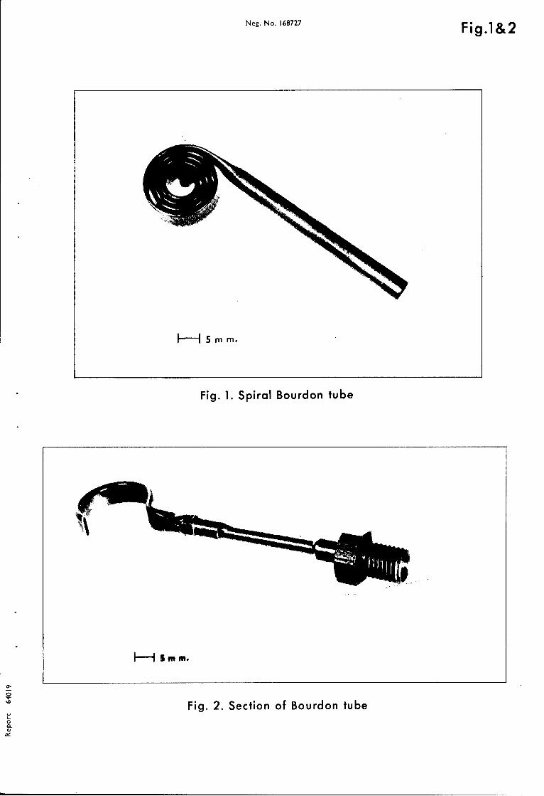
The transducer in its simplest form consists of a Bourdon tube sealed at
one end and coiled into a spiral somewhat similar to the mainspring of a clock
(Fig.l). The outer open end is fixed to the transducer case and the sealed
inner turn of the tube is attached to a spindle which is supported between
bearings. When pressure is applied to the open end of the tube the turns of
the spiral move relative to one another and as a consequence the spindle
rotates. The spindle can be made to operate a potentiometer wiper or any other
suitable device and the degree of change in position of the indicator will be a
measure of the pressure applied to the transducer. In this design both ends of
the tube are restrained against unwanted movement in the plane of the spiral so
that the effects of acceleration forces are greatly reduced. Conventional
transducers with "C" shaped tubes have only one end of the pressure responsive
element fixed and are therefore liable to show large errors when subjected to
vibration and acceleration forces.
3.2 Choice of tube material
The transducer was designed to be capable of measuring the pressure of
corrosive liquids such as HTP. The Bourdon tube and its associated pressure
fittings were, therefore, made from a compatible material. Stainless steel
AISI 316 (EN58J) was chosen since it had previously been proved satisfactory
when used with corrosive media, and in addition, has reasonably good Bourdon
tube characteristics. AISI 316 stainless steel has the best corrosion
resisting properties of the several materials available for use as Bourdon
tubes, but other materials have superior spring rates and temperature
coefficients. Where HTP compatibility is not a particular requirement the
Bourdon tube could, with advantage, be made from Ni-Span-C which is an age
hardened alloy of nickel, chrome and iron to which titanium has been added.
Seegers3 gives the following table of relative ratings of Bourdon tube material
properties:-
5
Resistance Spring Temperature Hysteresis TotalsMaterial to rate coefficient
corrosion
Beryllium 1 6 1 6 14copper
AISI 316 6 2 1 2 11stainlesssteel
Chrome 1 4 1 4 10molybdenumsteel
Ni-Span-C 5 5 6 5 21
*The higher the rating the better the material property.
For low pressure measurements AISI 316 can be formed into a tube with a
maximum diameter of 0.25 inch and a wall thickness, at this diameter, drawn
down to 0.0005 inch. A tube having these dimensions and subsequently r6lled
into a Bourdon section with a major axis of 0.354 inch and a minor axis of
0.045 inch will, according to Goitein4 , have an approximate pressure range of
0 to 0.5 lb/in 2. Goitein's formula, which gives good results in practice, is
as follows:-
fmax =(\2 + /A-B 2
where f = maximum stress (lb/in2 )max
P = internal pressure (lb/in2 )
t = wall thickness (inches)
A = mean major axis (inches)
B = mean minor axis (inches).
The maximum value of the permissible stress in stainless steel AISI 316 is
75,000 lb/in2 5 but the spiral tubes used in this design of transducer are
worked at a much lower value so as to obtain thebest possible' linearity,
hysteresis and repeatability performance.
3.3 Rollin. anI forming sTiral tubes
A selected length of stainless steel tubing is first rolled into the
cross-section as shown in Fig.2. After having been formed to this shape the
6
tube is wound into a spiral of the correct size and spacing and the end of the
inner turn welded to seal off the tube, after having ensured that any low-melting
point filling alloy which may have been used in this process is completely
removed from the tube interior. During the winding process great care must be
taken to avoid forming corrugations, kinks or other discontinuities in the tube
and to see that an even spacing is maintained between the turns of the spiral.
A machine for producing spiral tubes, with wall thicknesses varjing from
0.0005 inch to 0.025 inch is shown in Fig.3. All the tubes used in the numerous
experimental transducers of this type were wound on this machine and no
difficulty has been experienced in maintaining the correct shape, spacing and
performance of the spirals, although the undoubted skill of the operator should
not be overlooked. The end of the sealed inner turn of the spiral is prepared
as shown in Fig.4 and subsequently fastened to the transducer spindle by means
of a "Selock" pin as shown in the drawing.
3.4 Stabilising and stress relieving the soiral Bourdon tubes
During the winding process it is most essential that the spiral be
frequently heat-treated to ensure that the tube material is not being
excessively work-hardened and to help in preventing additional tube flattening
which may occur if unnecessarily large winding forces are used. After the
spiral has been wound it must be finally heat-treated at the correct temperature
to remove local stresses and to ensure a constant Young's modulus throughout the
whole length of the tube. A considerable amount of experimental effort was
necessary to make multi-turn stainless steel Bourdon tubes with good linearity,
hysteresis and repeatability characteristics and with an overall spiral diameter
not exceeding 0.875 inch. By careful appraisal of the heat-treatment processes
coupled with the use of a specially designed jig for filling the tube with low
melting point alloy, it has been proved possible to make spiral Bourdon tubes
with five turns and an overall diameter approximately 0.875 inch. The turn to
turn spacing is of the order 0,010 inch and the major to minor axis ratio
about 5 : I.
Spiral tubes have also been made from beryllium copper where the processes
involved are very similar to those required for stainless steel; the main
differences are intho temperatures necessary for the various heat-treatments
and the amount of "spring-back" to be allowed during the winding of the coil.
7
4 DEPOSITED TRACK POTENTIOMETERS
4.1 Design features
During the early design studies of this transducer it became apparent
that a number of advantages were possible by incorporating a deposited track
potentiometer instead of the more conventional wire wound unit. Three of the
most important features associated with deposited track potentiometers are
(a) freedom of choice regarding the substrate or former shape, (b) the ability
to have the oxide track laid down to any preferred contour, (c) continuous
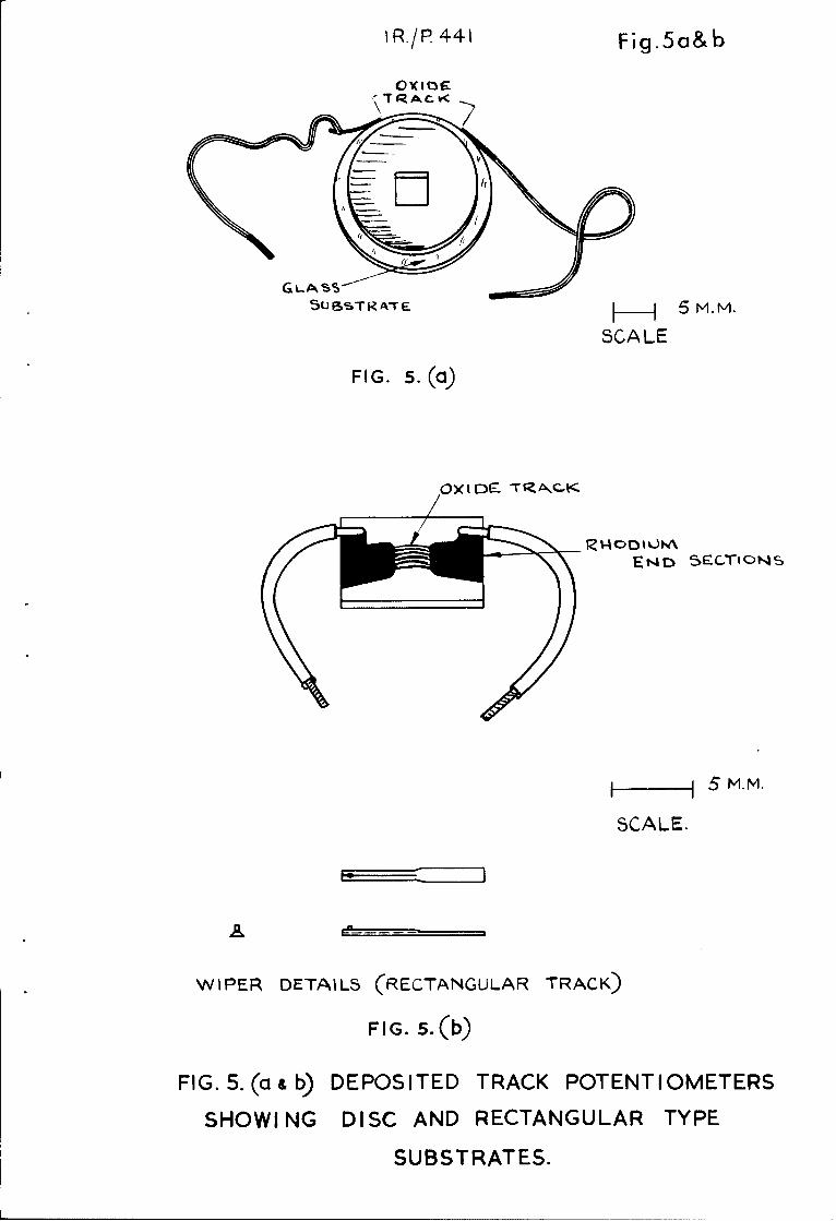
resolution. Early experimental models of the spiral transducer were fitted
with disc-shaped deposited track potentiometers made from borosilicate glass
about 3 inch diameter and 1/16 inch thick. The edge of the disc was flame
polished to give a slightly convex shape and the oxide film deposited around
part of the periphery Fig.5(a). A specially designed gold-alloy potentiometer
wiper made contact with the edge of the disc to form the pickoff. The potentio-
meter disc was attached to the spindle and rotated as the transducer was
pressurised; the stationary wiper in this case was fastened to an insulated
panel fitted to the body of the transducer. This style of potentiometer was not
proceeded with because an alternative design having a rectangular substrate with
curved deposited oxide track afforded better facilities for ranging the
instrument by varying the effective radius of the arm to which the potentiometer
wiper is attached. These latter type potentiometers had been developed by
Messrs G.V. Planer Ltd under a Ministry of Aviation contract; they are made from
polished "Pyrex" glass and have the ends of the track accurately defined by
rhodium plated sections flush with the oxide film. The potentiometer terminating
leads are soldered to the extremities of these rhodium sections and are
additionally secured by an epoxy resin. The wiper stylus associated with the
flat type of potentiometer is made from a gold-silver-copper alloy which is
compatible with the oxide track and in addition has been proved to have good
wear characteristics combined with minimum rotational noise and ease of fabrica-
tion. The actual style of wiper evolved for use with the flat deposited track
potentiometer is shown in Fig.5(b).
4.2 Electrical srecification
The electrical specification defining the performance of the deposited
track potentiometers is as follows:-
Resistance 1500 ohms ±10 per cent.
8 C
Linearity No error to exceed 0.15 per cent of full scale.
Nois.e The noise output voltage not to exceed 0.01 per cent
of the applied voltage.
Rotentiometer life Minimum of 100 000 sweeps without deterioration of
linearity or increase in noise level.
Maximum voltage 12 volts do.
Active length approximately 0.125 inch.
4.3 Environmental specification
The environmental specification for the deposited track potentiometers
is as follows:-
Shook test 100g for 5 milliseconds.
Vibration 30 0/s to 5000 c/s at a level of 1Og.
Temnerature range -400C to +80 0 C.
Additionally, the potentiometers must operate satisfactorily when immersed
in silicone fluid, or in dry conditions without silicone fluid.
5 CONSTRUCTION OF SPIRAL BOUMDON TUBE TRANSDUCER
5.1 Constructional materials
The case of the transducer may be constructed from either a corrosion-
resistant steel or a stable aluminium alloy which can be anodised to give
surface protection. In the latter case a considerable saving in weight can be
effected, but the Bourdon tube and its associated pressure fittings must be
made from a material compatible with the media being measured. In the models
so far constructed the tube and fittings have been made from AISI 316 (EN58J)
which is the best all round material for this purpose.
5.2 Transducer s-oindle bearings
The function of these bearings is to support the ends of the spindle or
arbor which positions the inner turn of the spiral tube assembly. It is of
paramount importance that the bearings be of the highest quality with the lowest
possible friction and "breakaway" torque so as not to impair the performance of
the transducer. The bearings ultimately chosen for this purpose are manufactured
by the Barden Corporation of America, who hold the patent for this particular
type of bearing. They are made of stainless steel with the stainless steel balls
pocketed in PTFE, a solid, low-friction non-deteriorating material which replaces
9 9
the oil or grease generally employed in conventional bearings. Double dust
shields are fitted to assist in keeping out foreign matter and to help preserve
the bearing performance which is so impbrtant in this particular application.
Insofar as the transducers may be held in store for long periods, theabsence of a conventional lubricant is an advantage.
5.3 Bourdon tube pressure element
As previously mentioned in this Report, the Bourdon tube is coiled into
a spiral so that the dimensions of the transducer can be kept to a minimum andin addition the advantages associated with a long active length of tube can be
fully exploited. In general, the size of a Bourdon tube pressure transducer
is related to the length of tube which can be accommodated within the instrumentcase. For a "C" shaped tube a compromise is made whereby a tube of modest
length, 2½ inches to 3 inches is used in combination with a mechanical lever
system or other form of multiplying device to give the required movement to the
potentiometer wiper or such alternative form of pressure indicator as may be
employed. In the spiral Bourdon transducer a pressure tube approximately12 inches long is used but due to its compact form the complete transducer can
be kept to a small size. Fig.6 is an "exploded" sketch showing how the tube
and its associated fittings are positioned relative to the transducer case.
5.4 Installation of spiral Bourdon tube transducer
To facilitate installation, the transducer has been arranged so that the
potentiometer leads are brought out via terminals which are adjacent to thepressure inlet connector as shown in Fig.7. Hence only one side need be
accessible and "side by side" mounting of a number of transducers can be
achieved with a consequent saving in space requirements.
6 PERFOPRMANCE
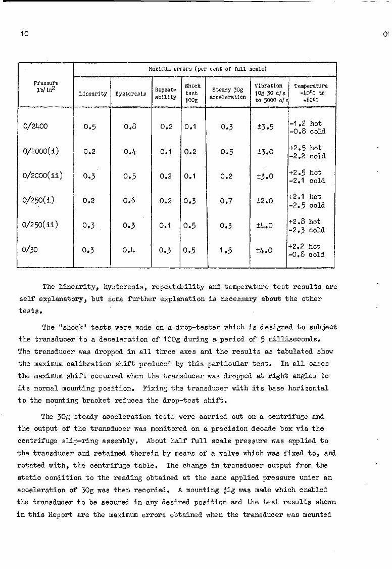
A number of models of the transducer covering different pressure ranges
have been made in Instrumentation and Ranges Department model shop and theperformance characteristics obtained from these transducers are shown in the
following table of results:-
A1 LDO 31 R.1
10 0
Maximur errors (per cent of full scale)
Pressure Vibration TemperatureRepeat- Shock Steady 30g V4rto tuLinearity Hysteresis ability test acceleration lOg 30 c/s -4O°C to
a lty to 5000 c/s' +800c-1.2
0/2400 0.5 0.8 0.2 0.1 0.3 ±3.5 -1.2 hot-0.8 cold
0/2000(i) 0.2 0.4 0.1 0.2 0.5 ±3.0 +2.5 hot-2.2 cold
0/2000(1i) 0.3 0.5 0.2 0.1 0.2 ±3.0 +2.5 hot-2.1 cold
0/250(i) 0.2 0.6 0.2 0.3 0.7 ±2.0 +2.1 hot-2.5 cold
0/250(11) 0.3 0.3 0.1 0.5 0.3 ±4,0 +2.8 hot-2.3 cold
0/30 0.3 0.4 0.3 0.5 1.5 ±4.O +2.2 hot-0.8 cold
The linearity, hysteresis, repeatability and temperature test results are
self explanatory, but some further explanation is necessary about the other
tests.
The "shock" tests were made on a drop-tester which is designed to subject
the transducer to a deceleration of 100g during a period of 5 milliseconds.
The transducer was dropped in all three axes and the results as tabulated show
the maximum calibration shift produced by this particular test. In all oases
the maximum shift occurred when the transducer was dropped at right angles to
its normal mounting position. Fixing the transducer with its base horizontal
to the mounting bracket reduces the drop-test shift.
The 30g steady acceleration tests were carried out on a centrifuge and
the output of the transducer was monitored on a precision decade box via the
centrifuge slip-ring assembly. About half full scale pressure was applied to
the transducer and retained therein by means of a valve which was fixed to, and
rotated with, the centrifuge table. The change in transducer output from the
static condition to the reading obtained at the same applied pressure under an
acceleration of 30g was then recorded. A mounting jig was made which enabled
the transducer to be secured in any desired position and the test results shown
in this Report are the maximum errors obtained when the transducer was mounted
9 11
in its most sensitive position, i.e. when the plane of the spiral is parallel
to the centrifuge table and the pressure connector pointing in the direction
of rotation.
All the vibration tests on the transducer were made at a level of lOg and
covered the frequency range 30 c/s to 5000 c/s. The transducers were vibrated
in all three axes and the errors shown were the maximum exhibited by the:
transducer during a resonance occurring at about 2000/2500 c/s. At other
frequencies the vibration errors were considerably less than those recorded
in the table of test results.
7 PROPOSALS FOR FURTHER DEVELOPMENT
It is considered that with additional development both absolute and
differential transducers can be made without greatly increasing the size of
the transducer case. In the differential version two identical spiral tubes
would be used connected to concentric spindles. One spindle would position the
potentiometer wiper whilst the other spindle would vary the position of the
potentiometer track according to the pressures applied to the Bourdon tubes.
The absolute model would have one of the two tubes at the vacuum reference
whilst the other would be available for measuring the varying pressure.
In the case of ultra low pressure spiral transducers, development will6
show that the use of the "rigid-beam" type of torsion suspension would have
worthwhile advantages and could replace the ball bearings used in the present
models. The "rigid-beam" suspension is a flexurally rigid torsion member which
does not have to be in tension as does the "taut-band" system. In its
symmetrical arrangement it consists of a cruciform cross-section and is able to
deflect through 25 degrees without the maximum shear stress in the torsion
members exceeding the endurance limit in shear. This type of suspension is
virtually frictionless (the friction being only the molecular friction of the
material, generally beryllium copper).
In the present design of spiral transducer, the wiper stylus associated
with the deposited track potentiometer is 0.008 inch diameter and the contact
end is polished to a hemispherical shape. The most suitable wiper pressure
has been found to be about 4 grams but when designing these very low pressure
transducers it may also be necessary to consider employing a lighter wiper
pressure so as to reduce the torque (about 0.33 gm/cm for a wiper pressure of
4. grams and a rotational radius of the wiper tip of 1 cm)7 . If this is done,
some form of damping will be required in order to reduce the errors due to
vibration. The deposited track potentiometers, as previously mentioned in this
12
Report, are suitable for use when immersed in silicone fluid and this liquid
could, therefore, be used as the damping, medium.
8 CONCLUSIONS
The performance results detailed in Section 6 of the Report show that
this design of miniature spiral tube transducer is capable of good overallaccuracy and that in particular the errors due to vibration and acceleration
are of a low value. The pressure range of this type of transducer using
Bourdon tube presently available from British sources is from about 30 lb/in2
to 2500 lb/in2 and this compares favourably with existing GIW transducers with
a more conventional tube configuration. The physical size and weight of the
transducer have been kept as small as possible so that it can be considered for
those applications where space is limited, and where the transducer weight must
be of a low value.
Further development may be necessary in the case of very 1ow pressure
models (below about 20 lb/in2 ) and a possible approach to this investigation
is the use of the "rigid-beam" torsion suspension together with some form of
internal damping of the transducer mechanism. It is considered that with some
additional development, both absolute and differential pressure models of this
transducer can be constructed using duplex tubes mounted on concentric spindles.
9 ACKNO0T.EDGEMENTS
The author wishes to put on record his appreciation of the help and
assistance given by Mr. A.W. Hiorns, formerly of the "Transducer Group,
Instrumentation and Ranges Department. Credit is due to Mr. E.N. Smith,
37 Dept, R.A.E. for the spiral winding machine design, and to Mr. S. Nettleingham
38 Dept, R.A.E. for micro-welding techniques.
13
REFERENCES
No. Author Title, etc
1 E.F. Price The design and testing of twisted Bourdon tube
potentiometer type pressure transducers.
(R.A.E. Technical Note No. TD 57)
2 Copper Development Copper in instrumentation, 39-4.8, 1955
Association
3 Hans Seegers Precision Bourdon-tube gauge.
Instruments and control systems, 34, No.2,
February 1961
4 K. Goitein Instrument practice, 6, No.11, September 1952
5 Allegheny-Ludlum Stainless steel fabrication
Steel Corporation,
Pittsburg, USA
6 P.J. Geary Rigid-beam torsion suspensions for electrical
measuring instruments.
BSIRA Report No. R.237, July 1958
7 G.V. Planer Ltd Development of continuous track oxide film
potentiometers.
April 1962
Neg. No. 168727 Fig.1&2
5 m M.
Fig. 1. Spiral Bourdon tube
0
0
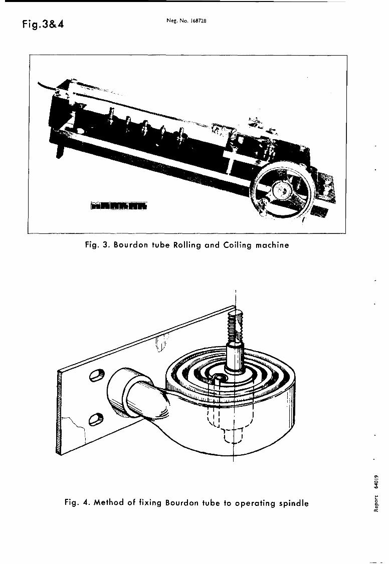
Fig.3&4 Neg. No. 168728
Fig. 3. Bourdon tube Rolling and Coiling machine
01
! i!
10
Fig. 4. Method of fixing Bourdon tube to operating spindle o
I R/P. 441 Fig.5a&b
GLASS/
5U ST R AT E 7 M.M.
SCALE
FIG. 5.(a)
0XIOC. TVZANCdl
TRNODILA-A
EtNDE SECTIONS
-5 SM.M.
SCALE.
WIPER DETAILS (RECTANGULAR TRACK)
FIG. s.(b)
FIG. 5. (a & b) DEPOSITED TRACK POTENTIOMETERS
SHOWING DISC AND RECTANGULAR TYPE
SUBSTRATES.
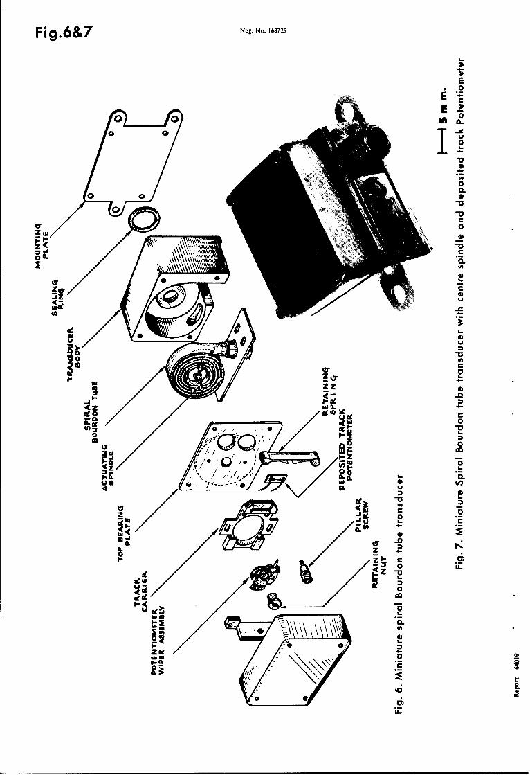
Fig.6&7 Neg. No. 168729
E.0
0 C0
za-
u-
4c4-
0 doe
Cb 1 0
00
IL.
J u-
* 10
01a
CbC-c 0
IETACHAN.E ABSTRACT CARDS
1 s.4 .-
a
Egg
fa s.. Vo '. d V
vc Vw toIDV-0'
0 OD 0 -
a. Iwo I~~ -V. 4,
-o 4. 2 o
00
CO o-4 Iv- Hao, -I I
In.H H -
cacr
.4.
41 4 , wV 00
on~ 000 pq 040,
10 0 4.)
i 0
4- .0 -
cd 0
42 0
Z f- v0 4ýH . 1 E ,4 I :jEQ~F-42 q.. P a