Embed Size (px)
Citation preview
AC 2011-2748: A MODERN EDUCATION POWER ELECTRONICS LAB-ORATORY TO ENHANCE HANDS-ON ACTIVE LEARNING
Sanghun Choi, Purdue University
Sanghun Choi received the B.Sc. degree in electrical engineering from the University of Illinois in UrbanaChampaing (UIUC), in 2009. He is currently working towards his M.Sc. degree in the School of Electricaland Computer Engineering at Purdue University.
Maryam Saeedifard, Purdue University
Maryam Saeedifard received the Ph.D. degree in electrical engineering from the University of Toronto,Toronto, ON, Canada, in 2008. From 2007 to 2008, she was a Visiting Research Associate with the PowerElectronic Systems Group, ABB Corporate Research Center, Dttwil-Baden, Switzerland. Subsequent toher graduation, she joined the Center for Applied Power Electronics in the Department of Electrical andComputer Engineering at the University of Toronto, as a Postdoctoral Fellow. Currently, she is an Assis-tant Professor at Purdue University, West Lafayette, IN. Her research interests include power electronicsand applications of power electronics in power systems. Dr. Saeedifard was the recipient of the NSERCPostdoctoral Fellowship of the Government of Canada in 2008 and the Richard M. Bass OutstandingYoung Power Electronics Engineer award of the IEEE Power Electronics Society in 2010.
Rohit Shenoy, MathWorks
Rohit Shenoy has been collaborating with university faculty to develop innovations in curricula that pre-pare students for successful careers. Previously he was marketing manager for MathWorks’ Controlsproducts and worked closely with customers in automotive and aerospace industries on modeling, simu-lation, and control design.
c©American Society for Engineering Education, 2011
A Modern Educational Power Electronics Laboratory to Enhance Hands-on Active Learning
Abstract – A new educational power electronics laboratory based on state-of-the-art tools and industrial-grade platforms is presented in this paper. The developed laboratory, which is built based upon prior theoretical knowledge and background of the students in power electronics, combines the sophisticated Texas Instruments (TI)’s hardware tools with MATLAB/Simulink software tools to design, test, and rapidly prototype power-electronic circuits. A detailed description of the tools along with their use in the developed laboratory is presented. Index Terms – Power electronics, digital control, micro-controller, MATLAB/Simulink environment, MATLAB Real Time Workshop, rapid prototyping. Introduction Power-electronic-based systems are being used in a wide range of applications including vehicular propulsion systems, industrial applications and motor drives, electromechanical motion control, and grid integration of renewable energy resources [1, 2]. The subject area of power electronics is multidisciplinary spanning a broad variety of subjects including circuits and signals analysis, electronics, digital control systems, and semiconductor devices. The importance of experimental learning of power electronics in support of the theoretical concepts is widely recognized [3]-[11]. An effective power electronics laboratory in today’s rapidly changing environment of daily technological breakthroughs should make a thread among those subjects by using state-of-the-art reconfigurable software/hardware tools. This paper presents a new power electronics laboratory. The primary purpose of the developed laboratory is to (i) experimentally reinforce the fundamental concepts presented in the power electronics course, thus providing a strong bridge between the theory and applications, (ii) provide the students with active learning experience in the design, digital control, and fabrication of power electronic circuits, (iii) introduce state-of-the-art simulation and experimentation tools for hands-on design, test, and rapid prototyping of power electronic converters, and expose the students to modern, yet simple and user-friendly, experimental facilities, and (iv) provide tailored experimental tools for further expansion and improvement of power electronics curriculum. The laboratory is designed and constructed based on a digital control platform using the Texas Instruments (TI) C2000 micro-controller in conjunction with the MATLAB/Simulink real-time tools. The power electronic circuits are designed, simulated, fabricated, and interfaced to the micro-controller by the students during the laboratory sessions. The students implement their developed Pulse Width Modulation (PWM) techniques in the MATLAB/Simulink environment to switch the power semiconductor devices on their fabricated circuits. Afterwards, they directly generate the executable codes, link, and download onto the micro-controller. This implementation procedure constitutes the concept of rapid prototyping in power electronics, which is a salient aspect of the new laboratory. The rapid prototyping feature allows students to focus on analyzing, prototyping, and commissioning of their designed power electronic circuits with reduced development time, without any involvement in C programming and by using the
user-friendly MATLAB/Simulink environment. Furthermore, the students get involved in the detailed process of design and implementation of power electronic circuits, as opposed to the black-box-based power electronics laboratories where the students are passively involved in wiring the hardware modules together and observing the waveforms. Another signature aspect of the laboratory is that it creates threads among courses such as signals and systems, digital signal processing, power electronics, and embedded systems, helping students retain knowledge across multiple disciplines. In this paper, a detailed description of the tools along with their use in the power electronics laboratory and the laboratory exercises is presented. Pedagogical Philosophy Power electronics is, by nature, a multi-disciplinary subject, and represents for any instructor a challenging topic to teach. It is an especially demanding course as it requires assimilation of a broad variety of topics, such as circuit analysis, signals and systems analysis, and control theory. It is widely accepted that hands-on experience in combination with a solid knowledge of theory provides an active learning environment that leads to successful learning in engineering topics. An effective power electronics laboratory is expected to combine theoretical and experimental aspects of the topics by using state-of-the-art software/hardware tools. The pedagogical approach seeks to combine industrial-grade technology with interactive learning strategies to reinforce the basic concepts of the power electronics course in the context of the innovative power electronics laboratory. The tools used in the laboratory are compatible with industrial-grade platforms and encompass both theoretical aspects of power electronics circuits and practical applications. The laboratory is built upon prior knowledge and background of the students, and is interdisciplinary with respect to the tools and skills required. For example, it combines knowledge in Digital Signal Processor (DSP)/micro-controller hardware/software platforms with power electronics to design and control the power electronic circuits. This signature aspect of the laboratory is intended to create threads among the related subjects to power electronics and retain the students’ knowledge across multiple disciplines. This pedagogical strategy goes beyond the “divide and conquer” strategy wherein each subject is relegated to its own course and then reduced and analyzed. Engineering education has traditionally followed such a strategy so that upon completion of the course, students find it unnecessary to draw upon the information learned from other courses, with the exception of more advanced courses on the same subject. This has been described as a “filtering” or non-retaining mode of education. The educational approach espoused in the new laboratory provides additional hands-on experiences to motivate students and help contextualize the course materials, and provide opportunities to explore the topics in greater depth. This pedagogical strategy in conjunction with the visualization capabilities of the laboratory tools motivates student-oriented discovery and provides a remarkable opportunity for active learning of power electronics. The Objectives The targeted audience for the laboratory is two sections of ten undergraduate students. The laboratory is a one-credit course, with three hours per week of laboratory time scheduled. It is
expected that each student entering the laboratory is taking the power electronics course as well. The power electronics course covers basics of semiconductor devices, dc-dc, dc-ac, and ac-dc converter topologies. Within the class, there is a strong emphasis on theoretical design and control issues, e.g., component design, thermal considerations, and effects of non-idealities on the converter. Even though these topics are important in their own right, students were never exposed to newer technologies that are becoming predominant in power engineering. Technical advantages of digital control, combined with the tremendous growth of DSPs have resulted in widespread adoption of digital control technology in all areas of power electronics applications. The lack of appropriate training on experimental aspects hampered students’ ability to advance and apply state-of-the-art power electronics technology for real-world applications. To address the mentioned issues, the main objectives of the proposed laboratory are:
• To experimentally reinforce and support the fundamental concepts presented in the lecture-based course in power electronics, thus providing an important bridge between theory and application and promoting active design-based learning.
• To provide the students with hands-on experience in design, prototyping, implementation, and testing the power electronic circuits.
• To introduce the students to the state-of-the-art industrial-grade simulation and experimentation tools.
• To expose the students to the measurement techniques and safety concerns in power electronics.
• To help students retain knowledge across multiple disciplines and go beyond the divide and conquer strategy.
• To provide students with a comprehensive understanding of industrial perspectives. The students are being trained with the state-of-the-art industrial-grade platforms for hands-on design, digital control, model-based design, embedded system control, rapid prototyping and testing, and commissioning of the converters with reduced development time. Thus, equipping the next generation of engineers with the skills to tackle problems make them more adaptable for industry with less effort on job training.
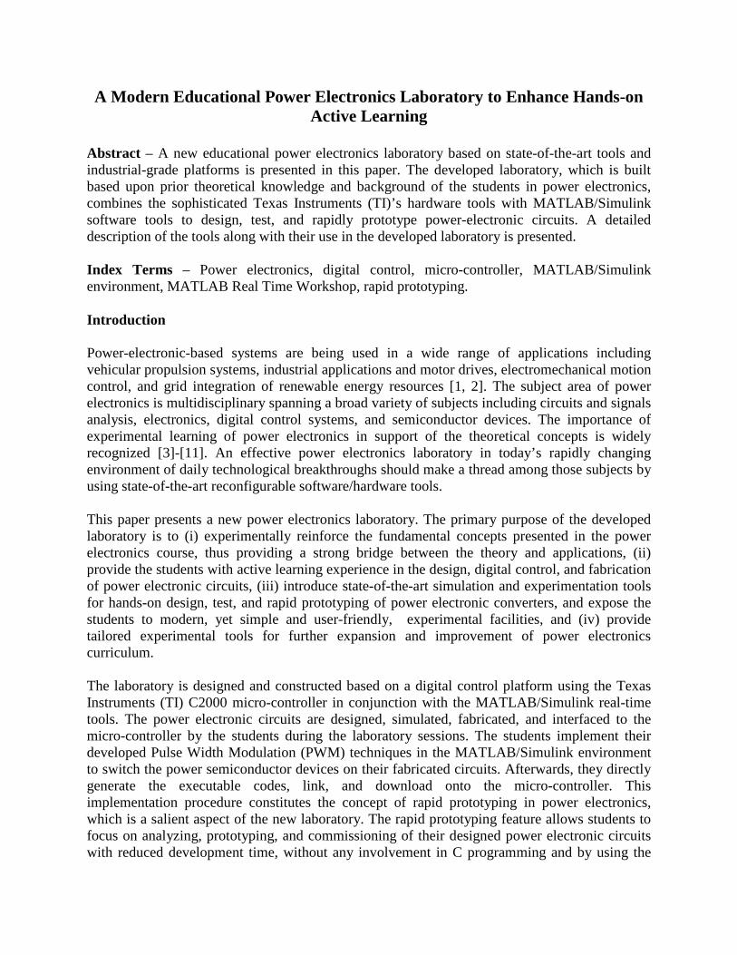
The Laboratory Facilities The developed laboratory consists of five identical power electronic stations. Each station accommodates two students and, as shown in Fig. 1, consists of: a computer for control and data capture/analysis, an oscilloscope for observing/capturing the waveforms, sensing equipment including current and voltage measurement probes, multi-meters, loads including dc and ac motors, batteries, a DSP/micro-controller board, passive components, semiconductor devices, and Printed Circuit Boards (PCBs) for power electronic circuit fabrication. The power electronic circuits during the introductory and training sessions are the built-in circuits of a TI C2000 Renewable Energy Developer’s (RED) kit [12], as shown in Fig. 1(a). During the experimental sessions, the power electronic circuits including dc-dc buck/boost converters and dc-ac inverters are designed and prototyped by the students, Fig. 1(b).
(a)
(b)
Fig. 1: Laboratory workstation for (a) built-in power electronic circuits on the TI C2000 RED kit, and (b) student’s designed and prototyped circuits.
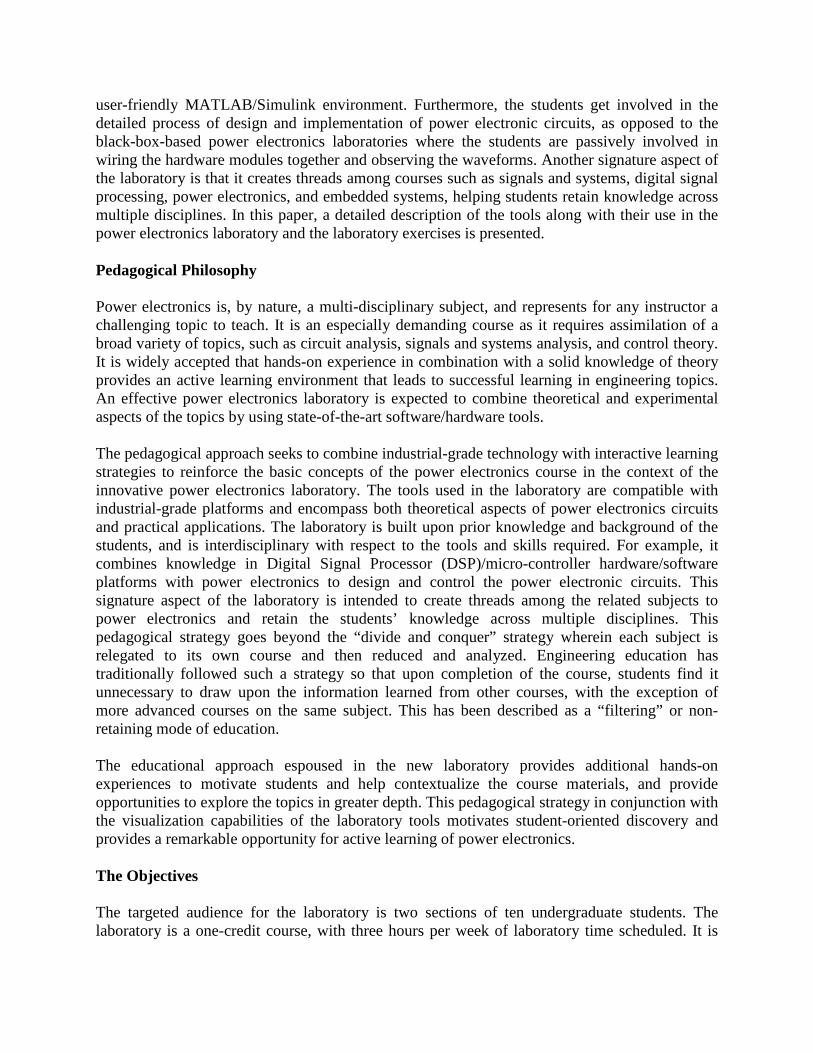
a. Integrated Development Environment
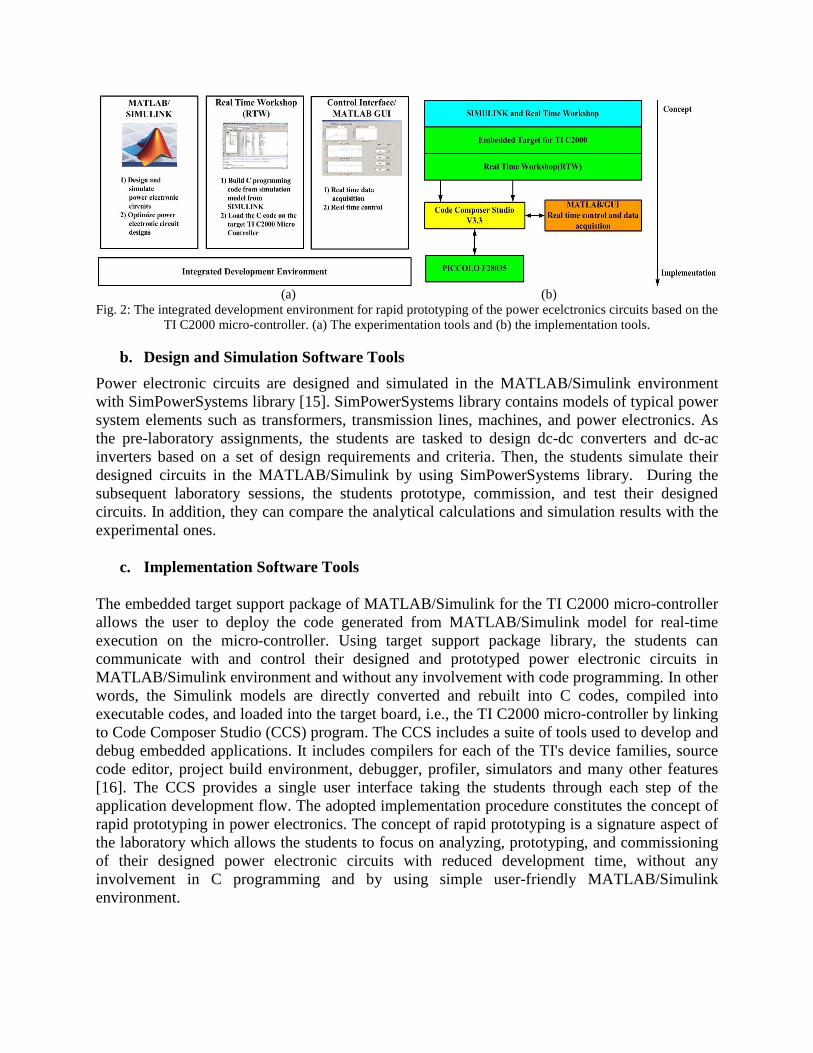
The concepts of rapid prototyping and digital control techniques in power electronics in the developed laboratory are realized based on using the TI C2000 micro-controller [13] in conjunction with the MATLAB/Simulink software based on an integrated development environment. The integrated development environment is a combination of software tools which allows implementation and experimentation processes to be carried out conveniently and interactively both under one single roof. As depicted in Fig. 2, MATLAB/Simulink environment is used for the design, optimization, and off-line simulations of the models and power electronic circuits. The MATLAB Real Time Workshop (RTW) converts the Simulink model to C programming code [14]. Subsequently, the C code is automatically compiled to the assembly language for the TI C2000 micro-controller, assembled, link-edited, and downloaded. Finally, MATLAB Graphical User Interface (GUI) is used to run, tune, and monitor the running process.
(a) (b)
Fig. 2: The integrated development environment for rapid prototyping of the power ecelctronics circuits based on the TI C2000 micro-controller. (a) The experimentation tools and (b) the implementation tools.
b. Design and Simulation Software Tools
Power electronic circuits are designed and simulated in the MATLAB/Simulink environment with SimPowerSystems library [15]. SimPowerSystems library contains models of typical power system elements such as transformers, transmission lines, machines, and power electronics. As the pre-laboratory assignments, the students are tasked to design dc-dc converters and dc-ac inverters based on a set of design requirements and criteria. Then, the students simulate their designed circuits in the MATLAB/Simulink by using SimPowerSystems library. During the subsequent laboratory sessions, the students prototype, commission, and test their designed circuits. In addition, they can compare the analytical calculations and simulation results with the experimental ones.
c. Implementation Software Tools
The embedded target support package of MATLAB/Simulink for the TI C2000 micro-controller allows the user to deploy the code generated from MATLAB/Simulink model for real-time execution on the micro-controller. Using target support package library, the students can communicate with and control their designed and prototyped power electronic circuits in MATLAB/Simulink environment and without any involvement with code programming. In other words, the Simulink models are directly converted and rebuilt into C codes, compiled into executable codes, and loaded into the target board, i.e., the TI C2000 micro-controller by linking to Code Composer Studio (CCS) program. The CCS includes a suite of tools used to develop and debug embedded applications. It includes compilers for each of the TI's device families, source code editor, project build environment, debugger, profiler, simulators and many other features [16]. The CCS provides a single user interface taking the students through each step of the application development flow. The adopted implementation procedure constitutes the concept of rapid prototyping in power electronics. The concept of rapid prototyping is a signature aspect of the laboratory which allows the students to focus on analyzing, prototyping, and commissioning of their designed power electronic circuits with reduced development time, without any involvement in C programming and by using simple user-friendly MATLAB/Simulink environment.
d. Experimentation Tools
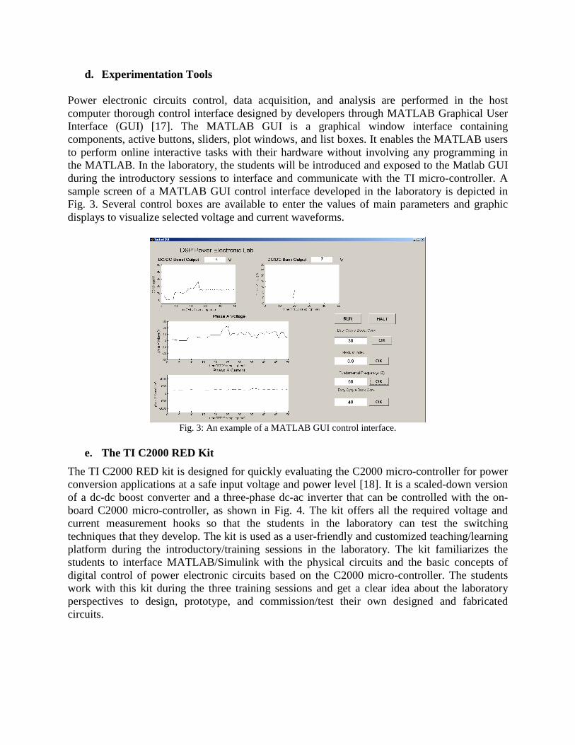
Power electronic circuits control, data acquisition, and analysis are performed in the host computer thorough control interface designed by developers through MATLAB Graphical User Interface (GUI) [17]. The MATLAB GUI is a graphical window interface containing components, active buttons, sliders, plot windows, and list boxes. It enables the MATLAB users to perform online interactive tasks with their hardware without involving any programming in the MATLAB. In the laboratory, the students will be introduced and exposed to the Matlab GUI during the introductory sessions to interface and communicate with the TI micro-controller. A sample screen of a MATLAB GUI control interface developed in the laboratory is depicted in Fig. 3. Several control boxes are available to enter the values of main parameters and graphic displays to visualize selected voltage and current waveforms.
Fig. 3: An example of a MATLAB GUI control interface.
e. The TI C2000 RED Kit
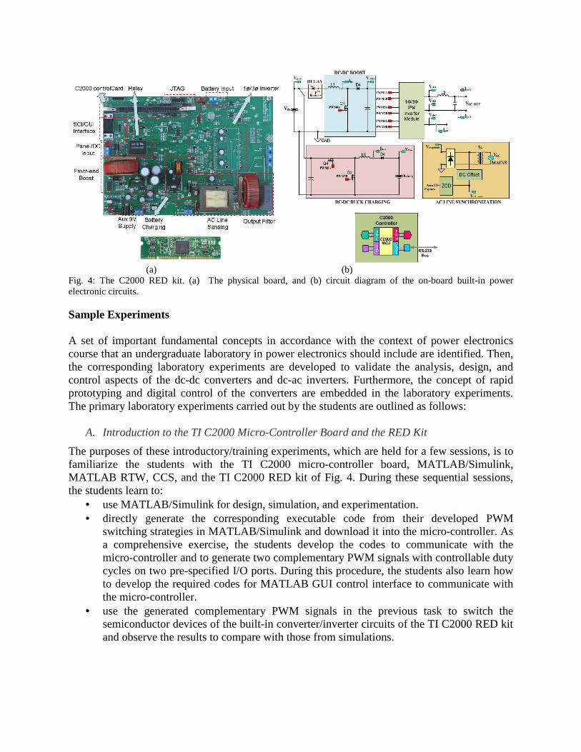
The TI C2000 RED kit is designed for quickly evaluating the C2000 micro-controller for power conversion applications at a safe input voltage and power level [18]. It is a scaled-down version of a dc-dc boost converter and a three-phase dc-ac inverter that can be controlled with the on-board C2000 micro-controller, as shown in Fig. 4. The kit offers all the required voltage and current measurement hooks so that the students in the laboratory can test the switching techniques that they develop. The kit is used as a user-friendly and customized teaching/learning platform during the introductory/training sessions in the laboratory. The kit familiarizes the students to interface MATLAB/Simulink with the physical circuits and the basic concepts of digital control of power electronic circuits based on the C2000 micro-controller. The students work with this kit during the three training sessions and get a clear idea about the laboratory perspectives to design, prototype, and commission/test their own designed and fabricated circuits.
(a) (b)
Fig. 4: The C2000 RED kit. (a) The physical board, and (b) circuit diagram of the on-board built-in power electronic circuits.
Sample Experiments A set of important fundamental concepts in accordance with the context of power electronics course that an undergraduate laboratory in power electronics should include are identified. Then, the corresponding laboratory experiments are developed to validate the analysis, design, and control aspects of the dc-dc converters and dc-ac inverters. Furthermore, the concept of rapid prototyping and digital control of the converters are embedded in the laboratory experiments. The primary laboratory experiments carried out by the students are outlined as follows:
A. Introduction to the TI C2000 Micro-Controller Board and the RED Kit
The purposes of these introductory/training experiments, which are held for a few sessions, is to familiarize the students with the TI C2000 micro-controller board, MATLAB/Simulink, MATLAB RTW, CCS, and the TI C2000 RED kit of Fig. 4. During these sequential sessions, the students learn to:
• use MATLAB/Simulink for design, simulation, and experimentation. • directly generate the corresponding executable code from their developed PWM
switching strategies in MATLAB/Simulink and download it into the micro-controller. As a comprehensive exercise, the students develop the codes to communicate with the micro-controller and to generate two complementary PWM signals with controllable duty cycles on two pre-specified I/O ports. During this procedure, the students also learn how to develop the required codes for MATLAB GUI control interface to communicate with the micro-controller.
• use the generated complementary PWM signals in the previous task to switch the semiconductor devices of the built-in converter/inverter circuits of the TI C2000 RED kit and observe the results to compare with those from simulations.
B. Gate Drive Circuits
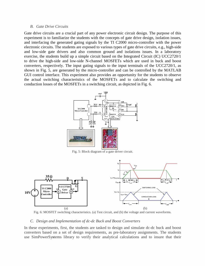
Gate drive circuits are a crucial part of any power electronic circuit design. The purpose of this experiment is to familiarize the students with the concepts of gate drive design, isolation issues, and interfacing the generated gating signals by the TI C2000 micro-controller with the power electronic circuits. The students are exposed to various types of gate drive circuits, e.g., high-side and low-side gate drivers and also common ground and isolations issues. In a laboratory exercise, the students build up a simple circuit based on the Integrated Circuit (IC) UCC2720/1 to drive the high-side and low-side N-channel MOSFETs which are used in buck and boost converters, respectively. The input gating signals to the input terminals of the UCC2720/1, as shown in Fig. 5, are generated by the micro-controller and can be controlled by the MATLAB GUI control interface. This experiment also provides an opportunity for the students to observe the actual switching characteristics of the MOSFETs and to calculate the switching and conduction losses of the MOSFETs in a switching circuit, as depicted in Fig. 6.
Fig. 5: Block diagram of a gate driver circuit.
(a) (b)
Fig. 6: MOSFET switching characteristics. (a) Test circuit, and (b) the voltage and current waveforms.
C. Design and Implementation of dc-dc Buck and Boost Converters
In these experiments, first, the students are tasked to design and simulate dc-dc buck and boost converters based on a set of design requirements, as pre-laboratory assignments. The students use SimPowerSystems library to verify their analytical calculations and to insure that their
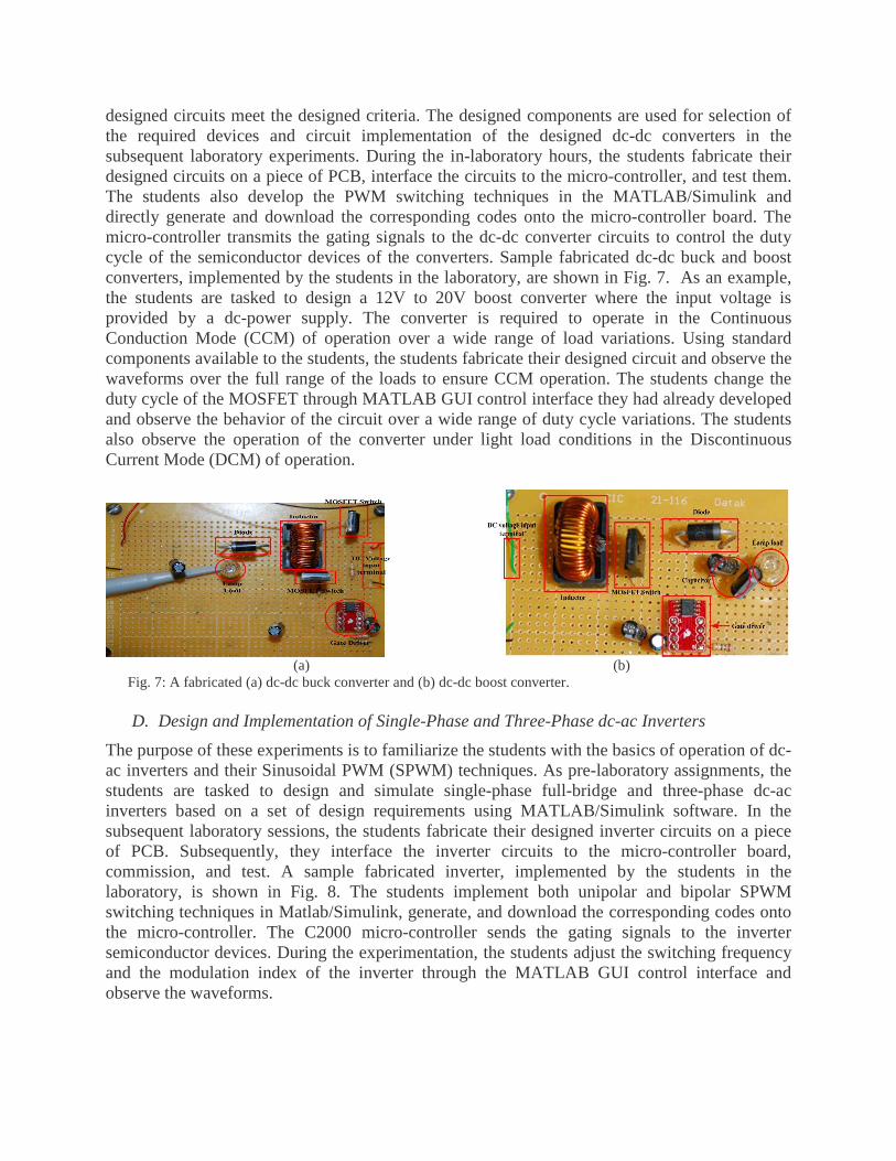
designed circuits meet the designed criteria. The designed components are used for selection of the required devices and circuit implementation of the designed dc-dc converters in the subsequent laboratory experiments. During the in-laboratory hours, the students fabricate their designed circuits on a piece of PCB, interface the circuits to the micro-controller, and test them. The students also develop the PWM switching techniques in the MATLAB/Simulink and directly generate and download the corresponding codes onto the micro-controller board. The micro-controller transmits the gating signals to the dc-dc converter circuits to control the duty cycle of the semiconductor devices of the converters. Sample fabricated dc-dc buck and boost converters, implemented by the students in the laboratory, are shown in Fig. 7. As an example, the students are tasked to design a 12V to 20V boost converter where the input voltage is provided by a dc-power supply. The converter is required to operate in the Continuous Conduction Mode (CCM) of operation over a wide range of load variations. Using standard components available to the students, the students fabricate their designed circuit and observe the waveforms over the full range of the loads to ensure CCM operation. The students change the duty cycle of the MOSFET through MATLAB GUI control interface they had already developed and observe the behavior of the circuit over a wide range of duty cycle variations. The students also observe the operation of the converter under light load conditions in the Discontinuous Current Mode (DCM) of operation.
(a) (b)
Fig. 7: A fabricated (a) dc-dc buck converter and (b) dc-dc boost converter.
D. Design and Implementation of Single-Phase and Three-Phase dc-ac Inverters
The purpose of these experiments is to familiarize the students with the basics of operation of dc-ac inverters and their Sinusoidal PWM (SPWM) techniques. As pre-laboratory assignments, the students are tasked to design and simulate single-phase full-bridge and three-phase dc-ac inverters based on a set of design requirements using MATLAB/Simulink software. In the subsequent laboratory sessions, the students fabricate their designed inverter circuits on a piece of PCB. Subsequently, they interface the inverter circuits to the micro-controller board, commission, and test. A sample fabricated inverter, implemented by the students in the laboratory, is shown in Fig. 8. The students implement both unipolar and bipolar SPWM switching techniques in Matlab/Simulink, generate, and download the corresponding codes onto the micro-controller. The C2000 micro-controller sends the gating signals to the inverter semiconductor devices. During the experimentation, the students adjust the switching frequency and the modulation index of the inverter through the MATLAB GUI control interface and observe the waveforms.
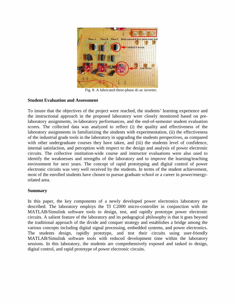
Fig. 8: A fabricated three-phase dc-ac inverter.
Student Evaluation and Assessment To insure that the objectives of the project were reached, the students’ learning experience and the instructional approach in the proposed laboratory were closely monitored based on pre-laboratory assignments, in-laboratory performances, and the end-of-semester student evaluation scores. The collected data was analyzed to reflect (i) the quality and effectiveness of the laboratory assignments in familiarizing the students with experimentation, (ii) the effectiveness of the industrial grade tools in the laboratory in upgrading the students perspectives, as compared with other undergraduate courses they have taken, and (iii) the students level of confidence, internal satisfaction, and perception with respect to the design and analysis of power electronic circuits. The collective institution-wide course and instructor evaluations were also used to identify the weaknesses and strengths of the laboratory and to improve the learning/teaching environment for next years. The concept of rapid prototyping and digital control of power electronic circuits was very well received by the students. In terms of the student achievement, most of the enrolled students have chosen to pursue graduate school or a career in power/energy-related area. Summary In this paper, the key components of a newly developed power electronics laboratory are described. The laboratory employs the TI C2000 micro-controller in conjunction with the MATLAB/Simulink software tools to design, test, and rapidly prototype power electronic circuits. A salient feature of the laboratory and its pedagogical philosophy is that it goes beyond the traditional approach of the divide and conquer strategy and establishes a bridge among the various concepts including digital signal processing, embedded systems, and power electronics. The students design, rapidly prototype, and test their circuits using user-friendly MATLAB/Simulink software tools with reduced development time within the laboratory sessions. In this laboratory, the students are comprehensively exposed and tasked to design, digital control, and rapid prototype of power electronic circuits.
References [1] F. Blaabjerg, Z. Chen, and S. B. Kjaer, “Power electronics as efficient interface in dispersed power
generation systems,” IEEE Trans. Power Electron., vol. 19, no. 5, pp. 1184–1194, 2004. [2] A. Emadi, Y. J. Lee, and K. Rajashekara, “Power electronics and motor drives in electric, hybrid electric,
and plug-in hybrid electric vehicles,” IEEE Trans. Ind. Electron., vol. 55, no. 6, pp. 2237–2245, 2008. [3] R. S. Balog, Z. Sorchini, J. W. Kimball, P. L. Champman, and P. T. Krein, “Modern laboratory-based
education for power electronics and electric machines,” IEEE Trans. Power Syst., vol. 20, no. 2, pp. 538-547, May 2005.
[4] W. G. Hurley and C. K. Lee, “Development, implementation, and assessment of a web-based power electronics laboratory,” IEEE Trans. Educ., vol. 48, no. 4, pp. 567-573, Nov. 2005.
[5] J.M. Williams, J.L. Cale, N.D. Benavides, J.D. Wooldridge, A.C. Koeing, J.L. Tichenor, and S.D. Pekarek, “Versatile hardware and software tools for educating students in power electronics, ” IEEE Trans. Educ., vol. 47, no. 4, pp. 436 - 445 , 2004.
[6] N. Mohan, W. P. Robbins, P. Imbertson, T. M. Undeland, R. C. Panaitescu, A. K. Jain, P. Jose, and T. Begalke, “Restructuring of first courses in power electronics and electric drives that integrates digital control,” IEEE Trans. Power Electron., vol. 18, no. 1, pp. 429-437, Jan. 2003.
[7] D. A. Torrey, “A project-oriented power electronics laboratory,” IEEE Trans. Power Electron., vol. 9. no. 3. pp. 250-255, May 1994.
[8] E. R. Collins, “An energy conversion laboratory using industrial-grade equipment,” IEEE Trans. Power Syst., vol. 24, pp. 3-11, Jan. 2009.
[9] J. M. Jimenez-Martinez, F. Soto, E. Jodar, J. A. Villarejo, and J. Roca-Dora, “A new approach for teaching power electronics converter experiments,” IEEE Trans. Educ., vol. 48, pp. 513-519, Aug. 2005.
[10] G. Venkataramanan, “A pedagogically effective structured introduction to electrical energy systems with coupled laboratory experiences,” IEEE Trans. Power Syst., vol. 19, pp. 129 -138, Feb. 2004.
[11] L. Max, T. Thiringer, T. Undeland, and R. Karlsson, “Power electronics design laboratory exercise for final-year M.Sc. students,” IEEE Trans. Educ., vol. 52, pp.524-531, Nov. 2009.
[12] C2000 Renewable Energy Developer’s Kit [Online]. Available : http://focus.ti.com/docs/toolsw/folders/prin t/tmdsenrgykit.html.
[13] TMS320F28035 [Online]. Available:http://focus.ti.com/docs/prod/folders/print/tms320f28035.html [14] Embedded IDE Link [Online]. Available: http://www.mathworks.com/products/ide- link/?s_cid=0909_
webg_9b_ccslink_trans_268513. [15] SimPowerSystems 5 [Online]. Available : http://www.mathworks.de/mason/tag/proxy.html? dataid=10665
&fileid [16] C2000 Getting Started with Code Composer Studio v4 [Online]. Available : http://processors.wiki.ti.com/
index.php?title=C2000_Getting_Started_with_Code_Composer_Studio_v4 [17] Creating Graphical User Interfaces [Online]. Available : http://www.mathworks.com/help/techdoc/
creating_guis/bqz79mu.html#creating_guis. [18] Implementing a Digitally Controlled Renewable Energy Systems with C2000 Micro-Controllers, Texas
Instruments Inc., Dallas, TX, 2009.