Embed Size (px)
Citation preview
A Multipurpose Vehicle Tracking System Based
on ARM CORTEX-M3 STM32, HMC5883L,
MPU-6050, GSM and GPS
Muhammad Husnain Ul Abdeen, Umar Shahbaz Khan, and Javaid Iqbal National University of Sciences and Technology, Islamabad, Pakistan, 44000
Email: [email protected], {u.shahbaz, j.iqbal}@ ceme.nust.edu.pk
Abstract—The paper presents the design and working
mechanism of a multipurpose vehicle tracking system using
latest microprocessor and telecommunication technologies.
Major components constituting the system are ARM
Cortex-M3 STM32 microcontroller, GSM (SIM900), GPS
(LR9548), HMC5883L Digital Magnetometer and MPU-
6050 Accelerometer. The entire system comprises 2
subsystems; one that resides in the vehicle (vehicle system)
and a remote monitoring system. The vehicle system
provides the monitoring system with GPS location and
bearing of the vehicle. At the monitoring system, a map
matching algorithm works in conjunction with the GPS
location and bearing to accurately determine and display
the road segment on which the vehicle travels. The tracking
system also apprises the user in the unfortunate case of
accidents using data from accelerometer and pressure
sensors. It is also equipped to stop the vehicle through an
ignition switching mechanism created with relays.
Index Terms—ARM Cortex, STM32, SIM900, LR9548,
HMC5883L, MPU-6050, accident alert, vehicle tracking,
map matching.
I. INTRODUCTION
The significant increase in world population has led to
a proportional increase in the demand of vehicles as a
necessity of life. With a plethora of vehicles on the roads,
news of deaths occurring due to road accidents have
become very common. Similarly, increase in crime
activities has also led to vehicles being stolen more often
[1].
Vehicle Tracking Systems [2]-[5] are an important
precaution that should be considered for ensuring life and
vehicle security since they are equipped to keep the user
informed about the vehicle’s location through
telecommunication. Vehicle tracking systems are of two
types, Passive and Active. Passive systems are the
simplest trackers which record the position of the vehicle.
These trackers can be later removed and transferred to a
computer for storage and analysis. Active car trackers are
the ones more commonly used and presented in this paper.
These systems possess the ability to transmit the vehicle’s
location in real time to a central location. However, in
most cases the GPS coordinates directly received by the
Manuscript received June 7, 2015; revised August 28, 2015.
system from the satellite can be somewhat inaccurate and
have to be processed or compared with sources
containing accurate positioning data to determine the
actual location of the vehicle. Most tracking systems
employ different Map Matching techniques [6]-[8] to
achieve this accuracy.
Active vehicle tracking systems are versatile and
provide many useful purposes. They can be used for
apprising the user through text messages about the
location of the vehicle which can be saved at a central
repository to keep history of the vehicle’s movements.
Many companies use this technology to monitor their
vehicles to make sure that the employees are performing
their duties hence it contributes to better management of a
company’s workforce [9]. Simultaneously, it also allows
the company to retrace its stolen vehicles. In case of theft,
based on the user’s command the system can also be used
to stop/lock the vehicle [10] usually by using relays
handling the vehicle ignition. Another advantage of using
these systems is that they can notify a remote user in case
an accident occurs. The system achieves this by applying
an intelligent program that processes data provided by
speed and pressure sensors in the vehicle to determine
whether such an event has occurred.
The vehicle tracking system presented in this paper has
2 subsystems; A vehicle system (resides in the vehicle)
that transmits vehicle’s GPS location and bearing via text
messages to a monitoring system that serves useful
purposes such as storing data from the vehicle system and
displaying it on a GUI for accurate visual tracking of the
vehicle by using a map matching algorithm. The results
of map matching when combined with the vehicle’s
bearing produce more reliable results.
II. SYSTEM FEATURES
The vehicle tracking system provides the following
useful operations:
a) Transmit GPS location and bearing of vehicle to the
user and central monitoring system when informed by the
user through SMS.
b) Based on the data provided by accelerometer and
pressure sensors, apprise the user through SMS in the
unfortunate event of an accident and also transmit
location and bearing of vehicle to monitoring system.
Journal of Traffic and Logistics Engineering Vol. 4, No. 1, June 2016
©2016 Journal of Traffic and Logistics Engineering 7doi: 10.18178/jtle.4.1.7-12
c) Acting on the user’s command, stop the vehicle by
using relays interfaced with the vehicle ignition. Send
location and bearing of vehicle to monitoring system and
user.
In all cases mentioned above, the monitoring system
extracts accurate vehicle positions using map matching
algorithm and vehicle’s bearing, stores them and displays
them on a GUI.
III. SYSTEM COMPONENTS
The components making up the vehicle system are:
ARM Cortex-M3 based STM32 F1 series
microcontroller
GSM (SIM900)
GPS (LR9548)
HMC5883L Digital magnetometer
Accelerometer (MPU-6050)
MAX 232
Pressure sensors
LCD
Relay
DC power supply
The components making up the monitoring system are:
GSM (SIM900)
MAX232
Computer system
Relay
DC power supply
IV. WORKING MECHANISM
The vehicle and monitoring system work in tandem to
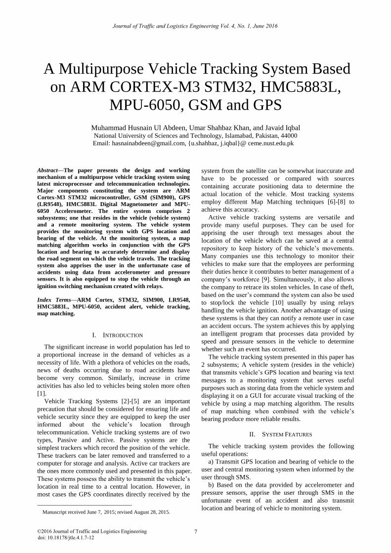
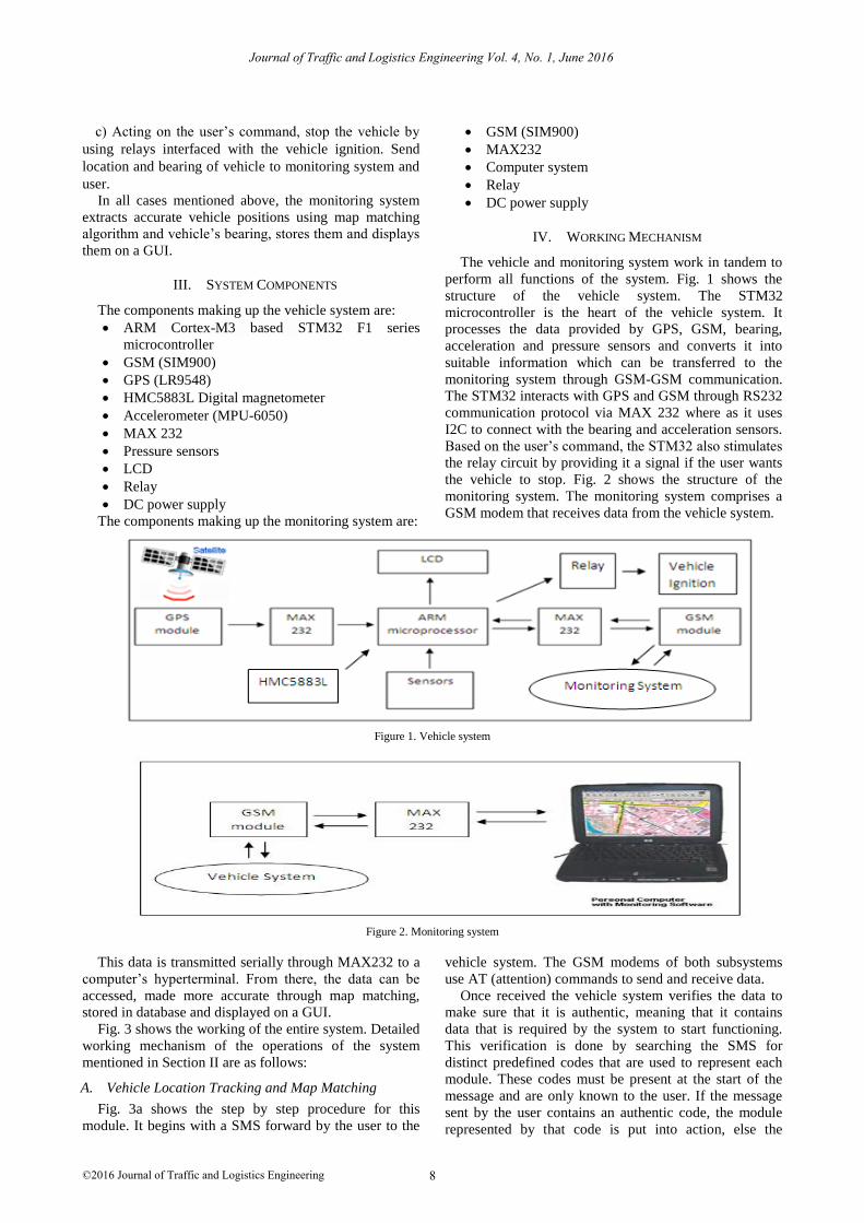
perform all functions of the system. Fig. 1 shows the
structure of the vehicle system. The STM32
microcontroller is the heart of the vehicle system. It
processes the data provided by GPS, GSM, bearing,
acceleration and pressure sensors and converts it into
suitable information which can be transferred to the
monitoring system through GSM-GSM communication.
The STM32 interacts with GPS and GSM through RS232
communication protocol via MAX 232 where as it uses
I2C to connect with the bearing and acceleration sensors.
Based on the user’s command, the STM32 also stimulates
the relay circuit by providing it a signal if the user wants
the vehicle to stop. Fig. 2 shows the structure of the
monitoring system. The monitoring system comprises a
GSM modem that receives data from the vehicle system.
Figure 1. Vehicle system
Figure 2. Monitoring system
This data is transmitted serially through MAX232 to a
computer’s hyperterminal. From there, the data can be
accessed, made more accurate through map matching,
stored in database and displayed on a GUI.
Fig. 3 shows the working of the entire system. Detailed
working mechanism of the operations of the system
mentioned in Section II are as follows:
A. Vehicle Location Tracking and Map Matching
Fig. 3a shows the step by step procedure for this
module. It begins with a SMS forward by the user to the
vehicle system. The GSM modems of both subsystems
use AT (attention) commands to send and receive data.
Once received the vehicle system verifies the data to
make sure that it is authentic, meaning that it contains
data that is required by the system to start functioning.
This verification is done by searching the SMS for
distinct predefined codes that are used to represent each
module. These codes must be present at the start of the
message and are only known to the user. If the message
sent by the user contains an authentic code, the module
represented by that code is put into action, else the
Journal of Traffic and Logistics Engineering Vol. 4, No. 1, June 2016
©2016 Journal of Traffic and Logistics Engineering 8
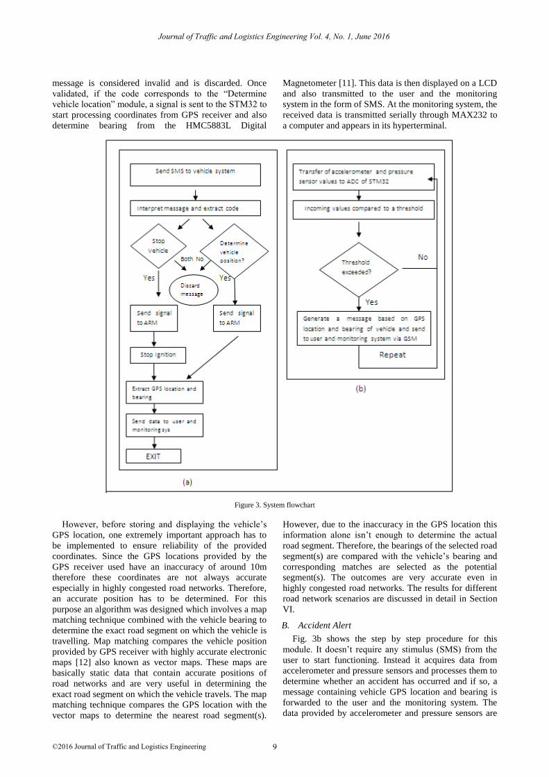
message is considered invalid and is discarded. Once
validated, if the code corresponds to the “Determine
vehicle location” module, a signal is sent to the STM32 to
start processing coordinates from GPS receiver and also
determine bearing from the HMC5883L Digital
Magnetometer [11]. This data is then displayed on a LCD
and also transmitted to the user and the monitoring
system in the form of SMS. At the monitoring system, the
received data is transmitted serially through MAX232 to
a computer and appears in its hyperterminal.
Figure 3. System flowchart
However, before storing and displaying the vehicle’s
GPS location, one extremely important approach has to
be implemented to ensure reliability of the provided
coordinates. Since the GPS locations provided by the
GPS receiver used have an inaccuracy of around 10m
therefore these coordinates are not always accurate
especially in highly congested road networks. Therefore,
an accurate position has to be determined. For this
purpose an algorithm was designed which involves a map
matching technique combined with the vehicle bearing to
determine the exact road segment on which the vehicle is
travelling. Map matching compares the vehicle position
provided by GPS receiver with highly accurate electronic
maps [12] also known as vector maps. These maps are
basically static data that contain accurate positions of
road networks and are very useful in determining the
exact road segment on which the vehicle travels. The map
matching technique compares the GPS location with the
vector maps to determine the nearest road segment(s).
However, due to the inaccuracy in the GPS location this
information alone isn’t enough to determine the actual
road segment. Therefore, the bearings of the selected road
segment(s) are compared with the vehicle’s bearing and
corresponding matches are selected as the potential
segment(s). The outcomes are very accurate even in
highly congested road networks. The results for different
road network scenarios are discussed in detail in Section
VI.
B. Accident Alert
Fig. 3b shows the step by step procedure for this
module. It doesn’t require any stimulus (SMS) from the
user to start functioning. Instead it acquires data from
accelerometer and pressure sensors and processes them to
determine whether an accident has occurred and if so, a
message containing vehicle GPS location and bearing is
forwarded to the user and the monitoring system. The
data provided by accelerometer and pressure sensors are
Journal of Traffic and Logistics Engineering Vol. 4, No. 1, June 2016
©2016 Journal of Traffic and Logistics Engineering 9
converted to digital values and fed to the STM32. An
algorithm continuously converts each digital value to a
number and creates pressure and acceleration gradients
based on incoming values in a certain time interval to
develop a good sense of the vehicles speed variation. The
use of pressure sensors makes this module very efficient.
Each gradient is compared with the previous one and
SMS flag generated in case both values differ more than a
certain threshold. The SMS flag indicates that an accident
has occurred and word (GPS location, bearing) is sent to
the user and monitoring system through SMS. At the
monitoring system this data can be processed to extract
and display the accurate road segment on which the
vehicle resides.
C. Vehicle Ignition Control
Fig. 3a shows the step by step procedure of this
module. It involves the use of relay connected to the
ignition loop. In case of theft, if the user wants the stop
the vehicle, he will send a “stop” SMS from his mobile
phone to the vehicle system. Once received, the vehicle
system will determine the validity of the question by
checking for an authentic code. If a match occurs it will
run the module represented by the code. In this case, the
STM32 will be signaled to turn of the relay and hence
stop the car. To apprise the user of the vehicles latest
location, a text message is prepared containing the
vehicle’s GPS location and bearing and communicated to
the user and the monitoring system.
V. GRAPHICAL USER INTERFACE (GUI)
The monitoring system stores the vehicle’s locations
and bearing in a database and also displays them on a
GUI. The database used for storing this data was made in
PostgreSQL software which is designed particularly for
Geographical Information System (GIS) applications.
This software provides queries and functions that can
be used for map matching of the vehicle’s GPS location.
A separate table was made in the database for storing the
geometry of the road networks on which the GPS location
was mapped to determine its nearest road segment. To
accomplish this, PostgreSQL provides a nearest neighbor
function called “pgis_fn_nn”. It requires inputs as follows:
The GPS location for which the nearest road
segment(s) is required.
The geometry of road network on which to
perform the nearest neighbor(s) search. This
geometry can be obtained from the Openstreet
map geographical Information data which is
opensource and available for GIS application
development.
The radius around the vehicle’s GPS location in
which the search must be performed. This was set
equal to the inaccuracy of the GPS receiver that is
10m. Hence, the search will be performed within a
circular buffer of 10m radius with the GPS
location at its center.
The number of nearest neighbors needed. Since
the number of nearest neighbors will be very small
in a circle of 10m radius therefore it can be set to a
small number such as 5.
Once the nearest road segment(s) are selected, their
bearings are calculated and compared with the vehicle’s
bearing. Each road segment stored in the database has its
own source (starting coordiante) and target (ending
coordinate). These coordinates are passed as input
arguments to a PostgreSQL function “st_azimuth” which
returns the north-based azimuth as the angle measured
clockwise from the vertical on source to target.
Segment(s) with bearings similar to the vehicle’s bearing
are selected as the final result. In many cases, only one
segment might have a bearing similar to the vehicle’s
bearing but this may not always be true. There are
scenarios where more than one road segment may match
the vehicle’s bearing. This is explained with an example
in section VI.
The map matching algorithm and GUI for displaying
the results were implemented through an HTML script
implemented in a NetBeans IDE. This HTML script
consists of 2 sub-scripts:
A script made in PHP programming language that
extracts the coordinates from the system
hyperterminal, connects with the PostgreSQL
database, implements the necessary PosdtgreSQL
functions and then stores the result in the database
to maintain history of the vehicle’s whereabouts.
The output of the nearest neighbor function is the
geometry of the nearest road segment(s) to the
vehicle’s location. This geometry is passed onto
the second script that is made in JavaScript.
JavaScript programming language is used to
develop the GUI. It uses a library called Open
Layers for displaying the geometry provided by
the PHP script on an Openstreet map. The user has
options to view current as well as the history of
the vehicle’s location.
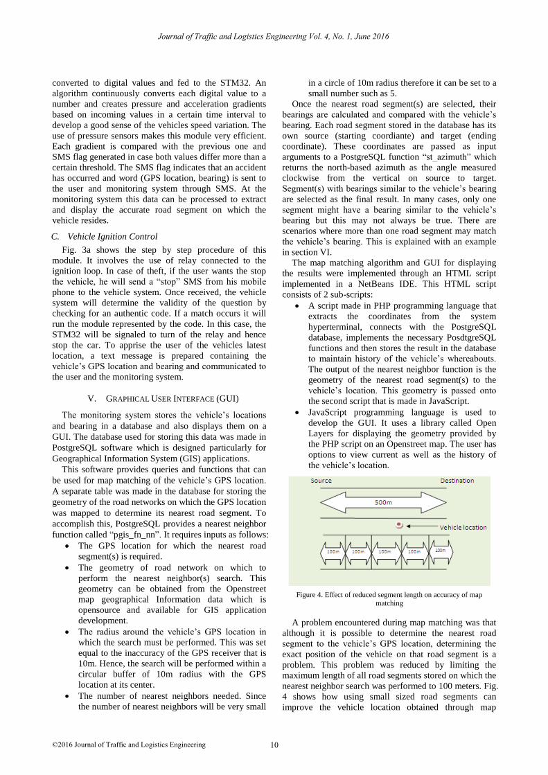
Figure 4. Effect of reduced segment length on accuracy of map matching
A problem encountered during map matching was that
although it is possible to determine the nearest road
segment to the vehicle’s GPS location, determining the
exact position of the vehicle on that road segment is a
problem. This problem was reduced by limiting the
maximum length of all road segments stored on which the
nearest neighbor search was performed to 100 meters. Fig.
4 shows how using small sized road segments can
improve the vehicle location obtained through map
Journal of Traffic and Logistics Engineering Vol. 4, No. 1, June 2016
©2016 Journal of Traffic and Logistics Engineering 10
matching. It shows a 500m road segment and another one
of the same length but divided into five segments of
100m each. If the nearest segment found to the vehicle
position shown is one 500m long segment, it will be more
difficult to identify the location of the vehicle on the road
since it can lie anywhere within that 500m distance.
However, if we use the 100m segments we can see that
the nearest neighbor to the vehicle would be the segment
200m to 300m from the source. Hence we determine a
smaller and more accurate range in which the vehicle lies.
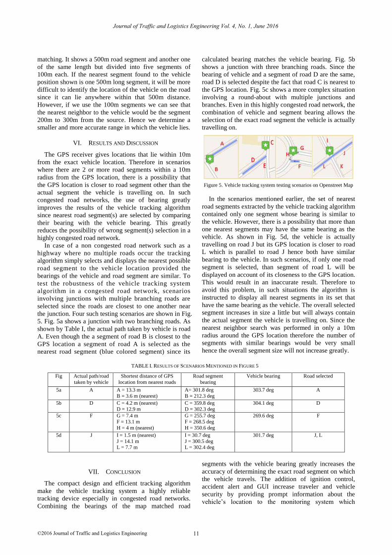
VI. RESULTS AND DISCUSSION
The GPS receiver gives locations that lie within 10m
from the exact vehicle location. Therefore in scenarios
where there are 2 or more road segments within a 10m
radius from the GPS location, there is a possibility that
the GPS location is closer to road segment other than the
actual segment the vehicle is travelling on. In such
congested road networks, the use of bearing greatly
improves the results of the vehicle tracking algorithm
since nearest road segment(s) are selected by comparing
their bearing with the vehicle bearing. This greatly
reduces the possibility of wrong segment(s) selection in a
highly congested road network.
In case of a non congested road network such as a
highway where no multiple roads occur the tracking
algorithm simply selects and displays the nearest possible
road segment to the vehicle location provided the
bearings of the vehicle and road segment are similar. To
test the robustness of the vehicle tracking system
algorithm in a congested road network, scenarios
involving junctions with multiple branching roads are
selected since the roads are closest to one another near
the junction. Four such testing scenarios are shown in Fig.
5. Fig. 5a shows a junction with two branching roads. As
shown by Table I, the actual path taken by vehicle is road
A. Even though the a segment of road B is closest to the
GPS location a segment of road A is selected as the
nearest road segment (blue colored segment) since its
calculated bearing matches the vehicle bearing. Fig. 5b
shows a junction with three branching roads. Since the
bearing of vehicle and a segment of road D are the same,
road D is selected despite the fact that road C is nearest to
the GPS location. Fig. 5c shows a more complex situation
involving a round-about with multiple junctions and
branches. Even in this highly congested road network, the
combination of vehicle and segment bearing allows the
selection of the exact road segment the vehicle is actually
travelling on.
Figure 5. Vehicle tracking system testing scenarios on Openstreet Map
In the scenarios mentioned earlier, the set of nearest
road segments extracted by the vehicle tracking algorithm
contained only one segment whose bearing is similar to
the vehicle. However, there is a possibility that more than
one nearest segments may have the same bearing as the
vehicle. As shown in Fig. 5d, the vehicle is actually
travelling on road J but its GPS location is closer to road
L which is parallel to road J hence both have similar
bearing to the vehicle. In such scenarios, if only one road
segment is selected, than segment of road L will be
displayed on account of its closeness to the GPS location.
This would result in an inaccurate result. Therefore to
avoid this problem, in such situations the algorithm is
instructed to display all nearest segments in its set that
have the same bearing as the vehicle. The overall selected
segment increases in size a little but will always contain
the actual segment the vehicle is travelling on. Since the
nearest neighbor search was performed in only a 10m
radius around the GPS location therefore the number of
segments with similar bearings would be very small
hence the overall segment size will not increase greatly.
TABLE I. RESULTS OF SCENARIOS MENTIONED IN FIGURE 5
Fig Actual path/road
taken by vehicle
Shortest distance of GPS
location from nearest roads
Road segment
bearing
Vehicle bearing Road selected
5a A A = 13.3 m
B = 3.6 m (nearest)
A= 301.8 deg
B = 212.3 deg
303.7 deg A
5b D C = 4.2 m (nearest)
D = 12.9 m
C = 359.8 deg
D = 302.3 deg
304.1 deg D
5c F G = 7.4 m
F = 13.1 m
H = 4 m (nearest)
G = 255.7 deg
F = 268.5 deg
H = 350.6 deg
269.6 deg F
5d J I = 1.5 m (nearest)
J = 14.1 m L = 7.7 m
I = 30.7 deg
J = 300.5 deg L = 302.4 deg
301.7 deg J, L
VII. CONCLUSION
The compact design and efficient tracking algorithm
make the vehicle tracking system a highly reliable
tracking device especially in congested road networks.
Combining the bearings of the map matched road
segments with the vehicle bearing greatly increases the
accuracy of determining the exact road segment on which
the vehicle travels. The addition of ignition control,
accident alert and GUI increase traveler and vehicle
security by providing prompt information about the
vehicle’s location to the monitoring system which
Journal of Traffic and Logistics Engineering Vol. 4, No. 1, June 2016
©2016 Journal of Traffic and Logistics Engineering 11
provides visuals of accurate past and present locations of
the vehicle.
[12] R. Anil Kumar, G. Jyothirmai, and K. RameshBabu, “Design and development of arm based embedded intelligent public transport
vehicle position system,” International Journal of Internet
Computing, vol. 1, no. 3, 2012.
Journal of Traffic and Logistics Engineering Vol. 4, No. 1, June 2016
©2016 Journal of Traffic and Logistics Engineering 12
REFERENCES
[1] S. S. Chakole, V. R. Kapur, and Y. A. Suryawanshi, “ARM
hardware platform for vehicular monitoring and tracking,” in Proc. International Conference on Communication Systems and
Network Technology, 2013.[2] Y. L. Zhao, Vehicle Location and Navigation Systems, Artech
House, 1997, pp. 83-103.
[3] Q. S. Zhang, J. P. Wu, and D. K. Yang, Intelligent Vehicle Positioning Navigation System and Its Application, Scientific
Publishing House, April 2002.[4] A. Khan and R. Mishra, “GPS – GSM based tracking system,”
International Journal of Engineering Trends and Technology, vol.
3, no. 2, pp. 161-169, 2012
[5] B. Kodavati and V. K. Raju, “Gsm and GPS based vehicle
location and tracking system,” International Journal of Engineering Research and Applications, vol. 1, no. 3, pp. 616-625,
2012.
[6] D. K. Yang, B. G. Cai, and Y. F. Yuan, “An improved map-matching algorithm used in vehicle navigation system,” IEEE
Intelligent Transportation Systems, vol. 2, pp. 1246-1250, 2003.[7] R. R Joshi, “A new approach to map matching for in-vehicle
navigation systems: The rotational variation metrics,” IEEE
Intelligent Transportation Systems, pp. 33-38, 2001.[8] R. R Joshi, “Novel metrics for map-matching in in-vehicle
navigation system,” in Proc. IEEE Intelligent Vehicle Symposium,2002, pp. 36-43.
[9] Z. Wen and J. Meng, “Design of vehicle positioning system based
on ARM,” in Proc. International Conference on Business Management and Electronic Information, 2011.
[10] V. Deepika, M. Suneel, M. Chiranjeevi, and T. Satya Vijay Swamy, “Vehicle engine locking system using, embedded based
GSM technology,” International Journal of Advances in
Computer Science And Cloud Computing, May 2013.[11] Three-axis Magnetic Sensor HMC5883L. (December 2012).
[Online]. Available: http://www.magneticsensors.com/three-axis-digital-compass.php
Mr. Muhammad Husnain Ul Abdeen
completed B.E Mechatronics from National
University of Sciences and Technology
(NUST), Pakistan and has also served as a Research Assistant at the graduate research
complex of NUST. He is an active participant
in multidisciplinary research. His research interests include Embedded systems, Robotics,
Object classification and recognition.
Dr. Umar Shahbaz Khan completed his PhD
from University of Liverpool, England and is currently an Assistant Professor at department
of Mechatronics Engineering at college of
Electrical and Mechanical Engineering, National University of Sciences and
Technology, Pakistan. His research interests
include Image processing, Embedded systems, Microcontrollers and Microprocessors and
Ground Penetrating Radar (GPR) data processing.
Dr. Javaid Iqbal completed his PhD from
University of New South Wales, Australia and is currently head of department at College of
Electrical and Mechanical Engineering,
National University of Sciences and Technology, Pakistan. His research interests
include Mobile Robots, Vision Systems and
Artificial Intelligence.