Embed Size (px)
Citation preview
This is a repository copy of A novel design of a desiccant rotary wheel for passive ventilation applications.
White Rose Research Online URL for this paper:http://eprints.whiterose.ac.uk/112307/
Version: Accepted Version
Article:
O’Connor, D., Calautit, J.K. and Hughes, B.R. (2016) A novel design of a desiccant rotary wheel for passive ventilation applications. Applied Energy, 179. pp. 99-109. ISSN 0306-2619
https://doi.org/10.1016/j.apenergy.2016.06.029
Article available under the terms of the CC-BY-NC-ND licence (https://creativecommons.org/licenses/by-nc-nd/4.0/)
[email protected]://eprints.whiterose.ac.uk/
Reuse
This article is distributed under the terms of the Creative Commons Attribution-NonCommercial-NoDerivs (CC BY-NC-ND) licence. This licence only allows you to download this work and share it with others as long as you credit the authors, but you can’t change the article in any way or use it commercially. More information and the full terms of the licence here: https://creativecommons.org/licenses/
Takedown
If you consider content in White Rose Research Online to be in breach of UK law, please notify us by emailing [email protected] including the URL of the record and the reason for the withdrawal request.
A Novel Design of a Desiccant Rotary Wheel for Passive Ventilation
Applications
DラマキミキI OげCラミミラヴ*1, John Kaiser Calautit1, Ben Richard Hughes1
1Department of Mechanical Engineering, University of Sheffield, Sheffield S10 2TN, UK
*Corresponding author: [email protected]
Abstract
Rotary desiccant wheels are used to regulate the relative humidity of airstreams. These are
commonly integrated into Heating, Ventilation and Air-Conditioning units to reduce the relative
humidity of incoming ventilation air. To maximise the surface area, desiccant materials are arranged
in a honeycomb matrix structure which results in a high pressure drop across the device requiring
fans and blowers to provide adequate ventilation. This restricts the use of rotary desiccant wheels to
mechanical ventilation systems. Passive ventilation systems are able to deliver adequate ventilation
air but cannot control the humidity of the incoming air. To overcome this, the traditional honeycomb
matrix structure of rotary desiccant wheels was redesigned to maintain a pressure drop value below
2Pa, which is required for passive ventilation purposes. In addition to this, the temperature of the
regeneration air for desorption was lowered. Radial blades extending out from the centre of a wheel
to the circumference were coated in silica gel particles to form a rotary desiccant wheel.
Computational Fluid Dynamics (CFD) modelling of the design was validated using experimental data.
Reduction in relative humidity up to 55% was seen from the system whilst maintaining a low
pressure drop across the new design. As an outcome of the work presented in this paper, a UK
patent GB1506768.9 has been accepted.
Keywords: Rotary desiccant wheel; Passive ventilation; Computational Fluid Dynamics;
Dehumidification; Rapid Prototyping; Wind Tunnel
Introduction
Uヮ デラ ΒヰХ ラa ; ヮWヴゲラミげゲ デキマW キゲ ミラ┘ ゲヮWミデ キndoors in a closed environment [1]. This means that the
indoor conditions to which occupants are subject to must conform to occupant demands, and should
be managed by systems capable of delivering these demands. Thermal comfort, good air quality to
maintain health, reliability and control of the system are all key to delivering satisfactory internal
conditions for occupants [2]. At present, this role is primarily fulfilled by mechanical Heating,
Ventilation and Air-Conditioning (HVAC) systems. Whilst mechanical HVAC systems are capable of
delivering the necessary conditions to occupants of comfortable indoor conditions, high energy
consumption of such systems contributes a significant amount of greenhouse gas emissions to the
climate. The construction, operation and maintenance of buildings accounts for 40% of the total
global energy consumption [3]. Within this sector, HVAC systems account up to 40% of the total
consumption [4]. Reducing the energy consumption of HVAC systems would substantially reduce the
energy consumption of buildings and lead to a reduction in greenhouse gas emissions [5].
The relative humidity of incoming supply air can have a significant impact on the energy
consumption of HVAC systems [6]. High relative humidity levels coupled with moderate-to-high air
temperature leads to discomfort to occupants, this is caused by high moisture levels in the air
preventing evaporation of ゲ┘W;デ aヴラマ デエW ゲニキミげゲ ゲ┌ヴa;IW [7]く Aゲ ゲ┘W;デ I;ミミラデ W┗;ヮラヴ;デWが デエW HラS┞げゲ natural cooling mechanism cannot operate effectively and so body temperature rises, increasing the
thermal discomfort felt by the occupant. By reducing the level of relative humidity in the air,
occupant comfort would increase. High moisture content of indoor air can also have serious health
implications for occupants. The presence of high moisture content and warm indoor air
temperatures can result in the growth of bacteria and mould [8]. The spores emitted from these
growths can affect occupant health, primarily relating to respiratory and skin problems [9]. Reducing
the relative humidity of indoor air and maintaining continuous ventilations prevents bacteria and
mould build-up.
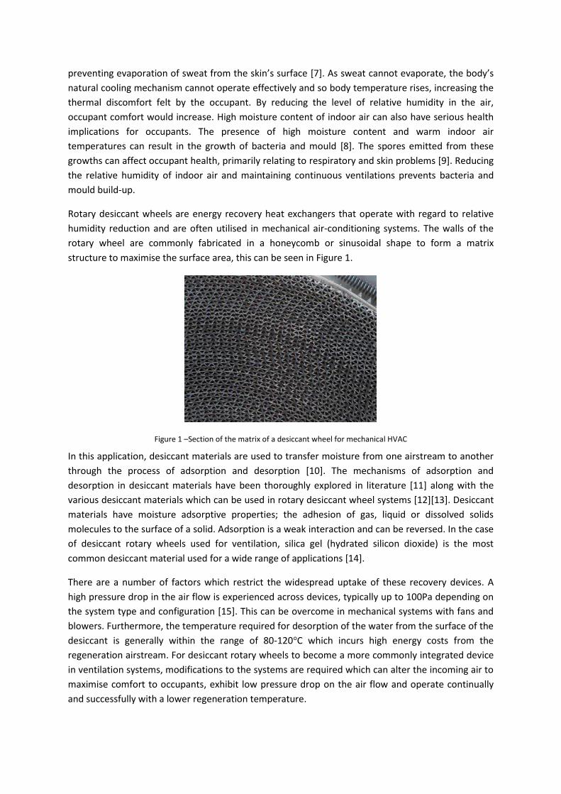
Rotary desiccant wheels are energy recovery heat exchangers that operate with regard to relative
humidity reduction and are often utilised in mechanical air-conditioning systems. The walls of the
rotary wheel are commonly fabricated in a honeycomb or sinusoidal shape to form a matrix
structure to maximise the surface area, this can be seen in Figure 1.
Figure 1 にSection of the matrix of a desiccant wheel for mechanical HVAC
In this application, desiccant materials are used to transfer moisture from one airstream to another
through the process of adsorption and desorption [10]. The mechanisms of adsorption and
desorption in desiccant materials have been thoroughly explored in literature [11] along with the
various desiccant materials which can be used in rotary desiccant wheel systems [12][13]. Desiccant
materials have moisture adsorptive properties; the adhesion of gas, liquid or dissolved solids
molecules to the surface of a solid. Adsorption is a weak interaction and can be reversed. In the case
of desiccant rotary wheels used for ventilation, silica gel (hydrated silicon dioxide) is the most
common desiccant material used for a wide range of applications [14].
There are a number of factors which restrict the widespread uptake of these recovery devices. A
high pressure drop in the air flow is experienced across devices, typically up to 100Pa depending on
the system type and configuration [15]. This can be overcome in mechanical systems with fans and
blowers. Furthermore, the temperature required for desorption of the water from the surface of the
desiccant is generally within the range of 80-120°C which incurs high energy costs from the
regeneration airstream. For desiccant rotary wheels to become a more commonly integrated device
in ventilation systems, modifications to the systems are required which can alter the incoming air to
maximise comfort to occupants, exhibit low pressure drop on the air flow and operate continually
and successfully with a lower regeneration temperature.
Rotary desiccant wheels operate by continuously rotating between two or more airstreams at a low
angular velocity. The airstreams have varying conditions; for example in a temperate climate such as
the UK, the inlet airstream is cooler with high relative humidity whereas the exhaust/regeneration
airstream is drier with a higher air temperature. The section of the wheel which is rotating through
an airstream with high relative humidity adsorbs moisture onto the desiccant. The process of
adsorption results in a temperature increase of the humid airstream, in certain climates this requires
the air to be cooled for thermal comfort. This two-step approach can incur significant additional cost
if systems are inappropriately designed. The continued rotation of the wheel results in the section of
the wheel which is saturated moving into the drier, hotter airstream. Here, desorption takes place
where the moisture on the surface of the desiccant is released into the airstream due to the high
temperature and low relative humidity, where the silica gel returns to its original state before
adsorption.
A new, and previously untested, structure for rotary desiccant wheels was conceptualised, designed
and tested to achieve these aims. By replacing the traditional honeycomb/sinusoidal wave matrix
structure of the desiccant wheel with blades which extend out from the centre of the wheel, it was
envisioned that a high levels of moisture adsorption could be achieved. Further aims of the
redesigned desiccant wheel were to lower the regeneration temperature and pressure drop across
the wheel due to the large openings between the blades, when compared to existing devices. The
ミW┘ SWゲキェミ ラa デエW ヴラデ;ヴ┞ SWゲキII;ミデ ┘エWWノが デWヴマWS ;ゲ デエW さヴ;Sキ;ノ Hノ;SW SWゲキェミざが ┘;ゲ analysed using
experimental testing to validate computational fluid dynamics (CFD) models for the same geometry.
3D prototyping was carried out to build the desiccant rotary wheel used to validate the CFD models.
No previous work has been conducted redesigning the structure of the desiccant wheel matrix to
reduce relative humidity levels and limit the pressure drop, enabling integration into a wind tower or
other passive ventilation system.
Previous Related Work
The rate at which the desiccant material adsorbs/desorbs moisture can be controlled by building
operators and so can regulate the relative humidity of the incoming air as conditions dictate [16].
Factors include the type of desiccant used, the amount of desiccant used, and the rotation speed of
the wheel, the depth of the wheel and the structure of the matrix [17]. Though maximising the
amount of desiccant within the rotary desiccant wheel leads to maximum moisture transfer; the
structural design and depth of the matrix results in a high pressure drop in the airstream [18]. The
high pressure drop in the incoming airflow results in inadequate ventilation rates to the building.
Additional high powered fans are installed in mechanical HVAC systems to overcome the high
pressure drop and provide suitable ventilation air [19]. However, the additional energy demand from
the high powered fans lead to increased energy consumption for the system as a whole. Though the
relative humidity of the incoming air is maintained at required levels for the occupants, the
increased energy consumption and cost requires evaluation [20]. Recent work has shown that
though the energy costs exist for energy consumption in these systems, a hybrid desiccant cooling
system, when compared to other air-conditioning systems, was effective at reducing energy
demands. However, the current initial capital costs are not offset the savings and so further
investigation is required [21].
The regeneration temperature, the temperature to which the exhaust air is raised to is another
process which requires high energy demand for successful operation of the system. The typical
regeneration air temperature required for desorption of the silica gel takes place can be as high as
120°C [22]. This further increases the high energy demand for the system as a whole. Attempts have
shown that lower regeneration temperatures are capable of maintaining desorption of the silica gel
[23]. It is important that desorption is maintained, allowing the silica gel to continue to adsorb the
moisture from the inlet air and improving comfort, if the desorption process is interrupted, the silica
gel may become completely saturated and no longer be capable of reducing the relative humidity of
the airstream by adsorption.
Reducing the regeneration air temperature as low as possible will result in lower overall energy
consumption and increase the attractiveness of the systems to building operators [24]. Other
research shows that desorption at lower regeneration temperatures may be possible when the
velocity of the inlet and regeneration air are controlled for optimum desorption [25]. Other sources
for regeneration heat have been explored, using solar energy in parabolic concentrators to increase
air temperature has shown positive results when coupled with a new system of desiccant
dehumidification [26].
In order to provide thermal comfort to occupants for a range of outdoor conditions with low energy
requirements, less conventional systems should be explored. Wind towers are a passive ventilation
system that are able to provide adequate ventilation air to a building with zero energy input [27]. By
manipulating the principles of pressure driven flow in the forms of wind flow and the stack
(buoyancy) effect, wind towers are more effective at providing ventilation than solely relying on
windows and openings [28]. Wind towers are becoming increasingly more common as ventilation
solutions in high occupant density buildings such as schools and commercial office spaces [29] and
have shown that along with the benefit of reducing the reliance on mechanical HVAC and reducing
energy consumption [30], wind towers provide fresh, clean outdoor air whilst extracting
contaminated air, improving the cognitive performance of occupants and providing a healthier
environment [31].
Despite the benefits of passive ventilation systems providing fresh, clean air whilst reducing energy
consumption, there are limitations to the operational window of wind towers [32]. In temperate
climates where the uptake of wind towers has been high, the operational window of wind towers is
limited by the external climate conditions. As wind towers ventilate by introducing outdoor air
directly into the occupied spaces, if the temperature of the external air falls outside the comfortable
range of conditions, the dampers are closed to prevent any outdoor air being introduced. The UK
Workplace (Health, Safety and Welfare) Regulations 1992 [33] sets a legal obligation on employers
and building managers to provide a working environment that is suitable for employees. The advised
temperature from the Approved Code of Practice is 16°C for the majority of working environments,
but can be lower for spaces where significant manual effort is conducted. When outdoor air
temperatures fall below 16°C, the operation of wind towers is not suitable. Equally, if the outdoor air
temperature rises above indoor air temperatures, commonly between 20-22°C, the introduction of
this air without conditioning will create discomfort for the occupants. This also applies to indoor
humidity level which ideally should be between 40-60%, a figure endorsed by HEVAC, CIBSE, BSRIA
and BR.
Integrating complimentary technologies into the ductwork below a wind tower which are capable of
modifying the incoming air, either through heating, cooling or drying, would be greatly beneficial to
building operators by increasing the operational window of wind towers. Examples of attempts to
couple these systems have been seen previously. Capturing heat from exhaust air and transferring it
to the incoming air would raise the temperature. This concept would reduce the energy required for
heating whilst providing clean air, various designs have been attempted and explored by a number
of research teams with different heat recovery devices [34,35]. As cooling of the incoming air is
required in hot climates, the installation of devices and techniques to reduce the incoming air
temperature have been attempted. These attempts include the use of heat pipes, evaporative
cooling, and thermal mass buildings among other designs [36,37]. High relative humidity levels,
which also affect thermal comfort of occupants, can be reduced by using desiccant systems, of which
there are a number of configurations[38に40]. Desiccant systems generally require coupling to a
cooling device also as the process of moisture removal increases air temperature, this leads to a
further pressure drop along with the high pressure drop of desiccant systems.
A major restriction integrating recovery devices into a wind tower is the high pressure drop
experienced across devices. Due to the low air velocity of incoming air in wind towers, a pressure
drop across a device 2Pa or above results in negligible supply air. Recovery devices have significantly
higher pressure drop, up to 100Pa. Though this is overcome in mechanical systems with fans and
blowers, the additional energy required for this configuration is seen as unsatisfactory and surplus
for a passive ventilation system. In order to extend the operational window of wind towers and
maintain the low energy consumption demands, modifications to the systems are required which
can alter the incoming air to maximise comfort to occupants. Devices which exhibit low pressure
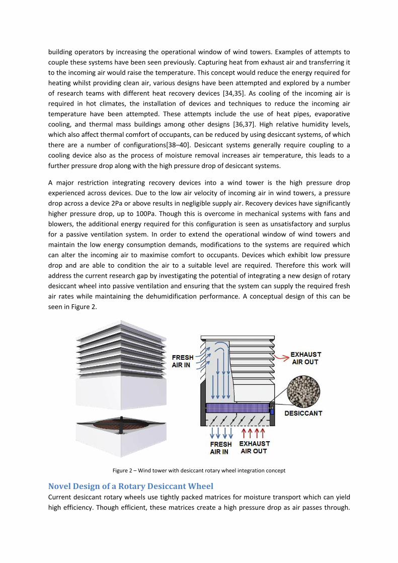
drop and are able to condition the air to a suitable level are required. Therefore this work will
address the current research gap by investigating the potential of integrating a new design of rotary
desiccant wheel into passive ventilation and ensuring that the system can supply the required fresh
air rates while maintaining the dehumidification performance. A conceptual design of this can be
seen in Figure 2.
Figure 2 に Wind tower with desiccant rotary wheel integration concept
Novel Design of a Rotary Desiccant Wheel
Current desiccant rotary wheels use tightly packed matrices for moisture transport which can yield
high efficiency. Though efficient, these matrices create a high pressure drop as air passes through.
This necessitates the use of high powered fans to force the required air through the wheel for
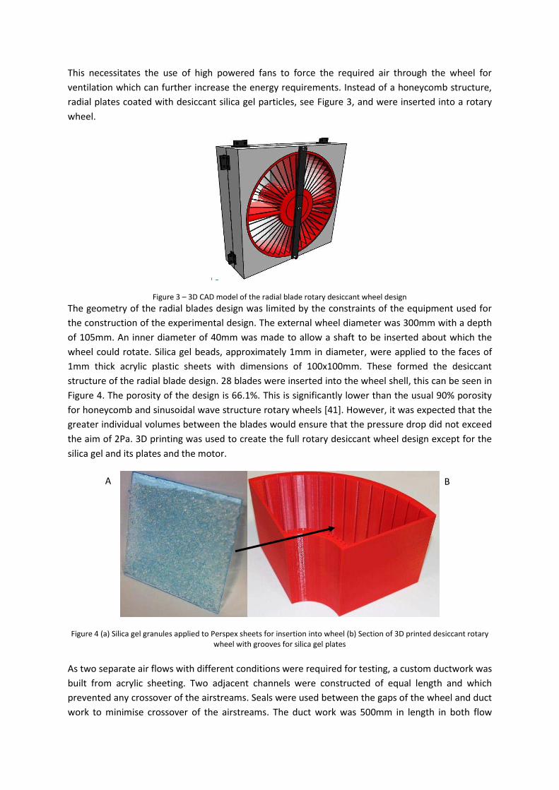
ventilation which can further increase the energy requirements. Instead of a honeycomb structure,
radial plates coated with desiccant silica gel particles, see Figure 3, and were inserted into a rotary
wheel.
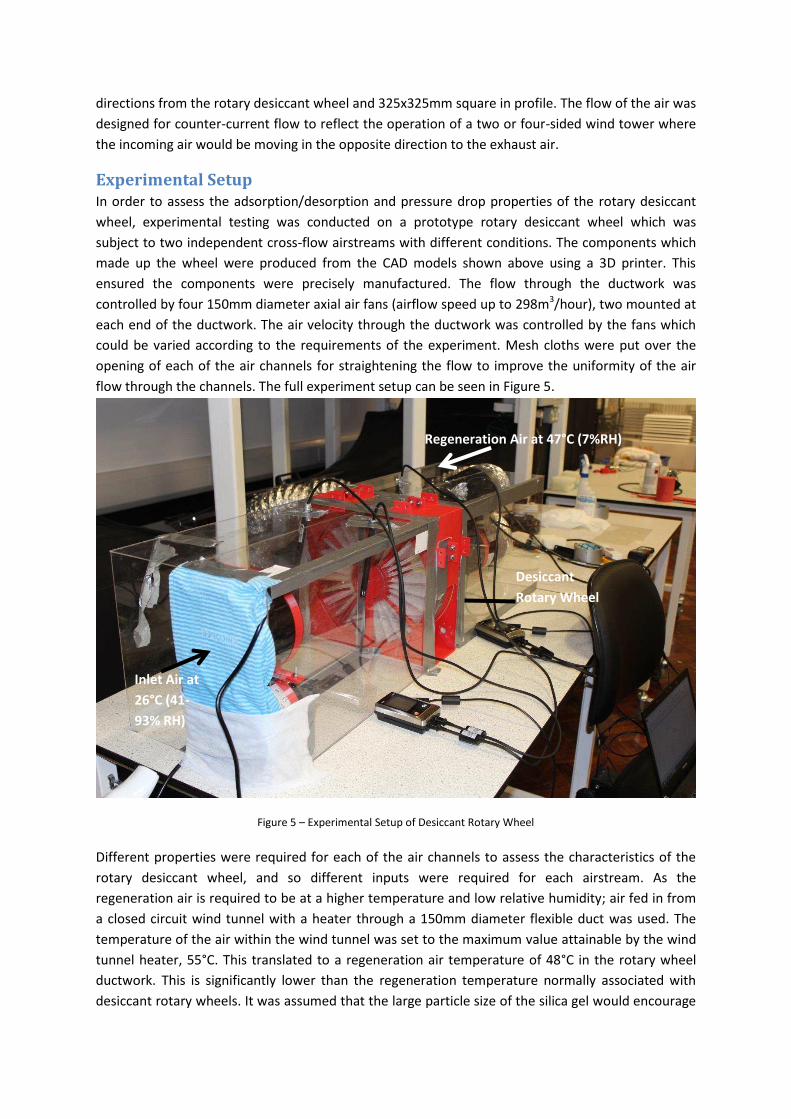
Figure 3 に 3D CAD model of the radial blade rotary desiccant wheel design The geometry of the radial blades design was limited by the constraints of the equipment used for
the construction of the experimental design. The external wheel diameter was 300mm with a depth
of 105mm. An inner diameter of 40mm was made to allow a shaft to be inserted about which the
wheel could rotate. Silica gel beads, approximately 1mm in diameter, were applied to the faces of
1mm thick acrylic plastic sheets with dimensions of 100x100mm. These formed the desiccant
structure of the radial blade design. 28 blades were inserted into the wheel shell, this can be seen in
Figure 4. The porosity of the design is 66.1%. This is significantly lower than the usual 90% porosity
for honeycomb and sinusoidal wave structure rotary wheels [41]. However, it was expected that the
greater individual volumes between the blades would ensure that the pressure drop did not exceed
the aim of 2Pa. 3D printing was used to create the full rotary desiccant wheel design except for the
silica gel and its plates and the motor.
Figure 4 (a) Silica gel granules applied to Perspex sheets for insertion into wheel (b) Section of 3D printed desiccant rotary
wheel with grooves for silica gel plates
As two separate air flows with different conditions were required for testing, a custom ductwork was
built from acrylic sheeting. Two adjacent channels were constructed of equal length and which
prevented any crossover of the airstreams. Seals were used between the gaps of the wheel and duct
work to minimise crossover of the airstreams. The duct work was 500mm in length in both flow
A B
directions from the rotary desiccant wheel and 325x325mm square in profile. The flow of the air was
designed for counter-current flow to reflect the operation of a two or four-sided wind tower where
the incoming air would be moving in the opposite direction to the exhaust air.
Experimental Setup
In order to assess the adsorption/desorption and pressure drop properties of the rotary desiccant
wheel, experimental testing was conducted on a prototype rotary desiccant wheel which was
subject to two independent cross-flow airstreams with different conditions. The components which
made up the wheel were produced from the CAD models shown above using a 3D printer. This
ensured the components were precisely manufactured. The flow through the ductwork was
controlled by four 150mm diameter axial air fans (airflow speed up to 298m3/hour), two mounted at
each end of the ductwork. The air velocity through the ductwork was controlled by the fans which
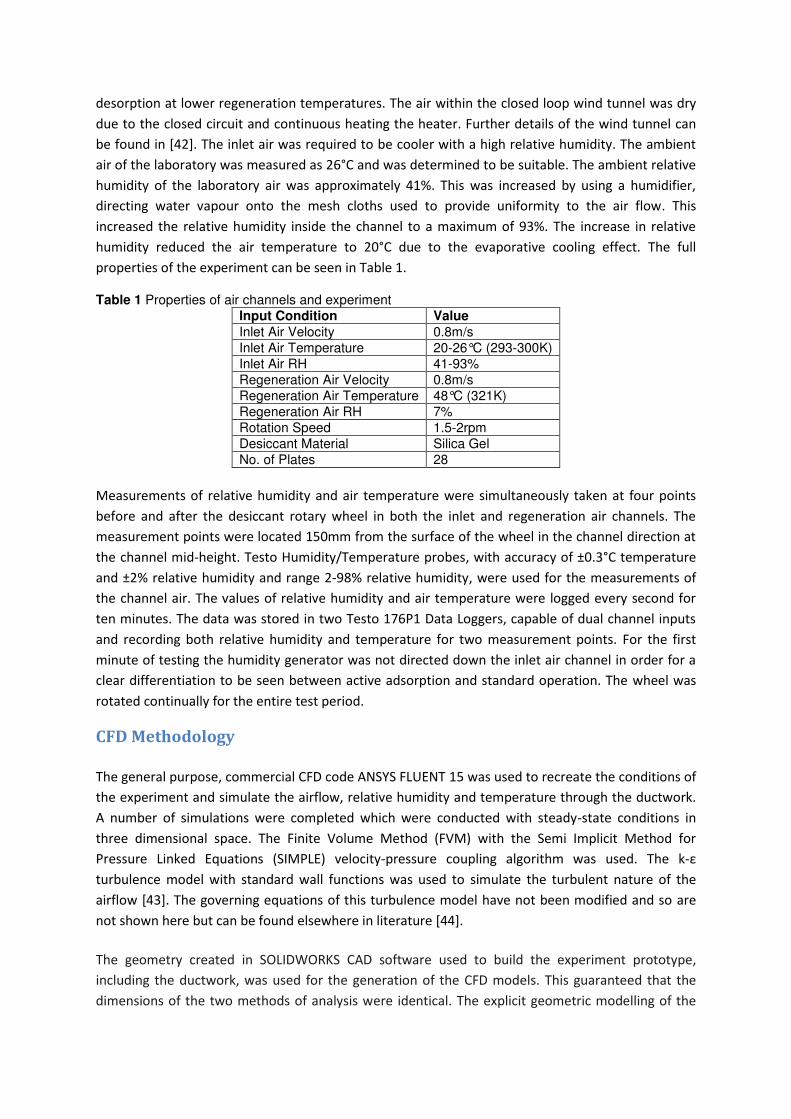
could be varied according to the requirements of the experiment. Mesh cloths were put over the
opening of each of the air channels for straightening the flow to improve the uniformity of the air
flow through the channels. The full experiment setup can be seen in Figure 5.
Figure 5 に Experimental Setup of Desiccant Rotary Wheel
Different properties were required for each of the air channels to assess the characteristics of the
rotary desiccant wheel, and so different inputs were required for each airstream. As the
regeneration air is required to be at a higher temperature and low relative humidity; air fed in from
a closed circuit wind tunnel with a heater through a 150mm diameter flexible duct was used. The
temperature of the air within the wind tunnel was set to the maximum value attainable by the wind
tunnel heater, 55°C. This translated to a regeneration air temperature of 48°C in the rotary wheel
ductwork. This is significantly lower than the regeneration temperature normally associated with
desiccant rotary wheels. It was assumed that the large particle size of the silica gel would encourage
Inlet Air at
26°C (41-
93% RH)
Regeneration Air at 47°C (7%RH)
Desiccant
Rotary Wheel
desorption at lower regeneration temperatures. The air within the closed loop wind tunnel was dry
due to the closed circuit and continuous heating the heater. Further details of the wind tunnel can
be found in [42]. The inlet air was required to be cooler with a high relative humidity. The ambient
air of the laboratory was measured as 26°C and was determined to be suitable. The ambient relative
humidity of the laboratory air was approximately 41%. This was increased by using a humidifier,
directing water vapour onto the mesh cloths used to provide uniformity to the air flow. This
increased the relative humidity inside the channel to a maximum of 93%. The increase in relative
humidity reduced the air temperature to 20°C due to the evaporative cooling effect. The full
properties of the experiment can be seen in Table 1.
Table 1 Properties of air channels and experiment
Input Condition Value
Inlet Air Velocity 0.8m/s
Inlet Air Temperature 20-26°C (293-300K)
Inlet Air RH 41-93%
Regeneration Air Velocity 0.8m/s
Regeneration Air Temperature 48°C (321K)
Regeneration Air RH 7%
Rotation Speed 1.5-2rpm
Desiccant Material Silica Gel
No. of Plates 28
Measurements of relative humidity and air temperature were simultaneously taken at four points
before and after the desiccant rotary wheel in both the inlet and regeneration air channels. The
measurement points were located 150mm from the surface of the wheel in the channel direction at
the channel mid-height. Testo Humidity/Temperature probes, with accuracy of ±0.3°C temperature
and ±2% relative humidity and range 2-98% relative humidity, were used for the measurements of
the channel air. The values of relative humidity and air temperature were logged every second for
ten minutes. The data was stored in two Testo 176P1 Data Loggers, capable of dual channel inputs
and recording both relative humidity and temperature for two measurement points. For the first
minute of testing the humidity generator was not directed down the inlet air channel in order for a
clear differentiation to be seen between active adsorption and standard operation. The wheel was
rotated continually for the entire test period.
CFD Methodology
The general purpose, commercial CFD code ANSYS FLUENT 15 was used to recreate the conditions of
the experiment and simulate the airflow, relative humidity and temperature through the ductwork.
A number of simulations were completed which were conducted with steady-state conditions in
three dimensional space. The Finite Volume Method (FVM) with the Semi Implicit Method for
Pressure Linked Equations (SIMPLE) velocity-pressure coupling algorithm was used. The k-0 turbulence model with standard wall functions was used to simulate the turbulent nature of the
airflow [43]. The governing equations of this turbulence model have not been modified and so are
not shown here but can be found elsewhere in literature [44].
The geometry created in SOLIDWORKS CAD software used to build the experiment prototype,
including the ductwork, was used for the generation of the CFD models. This guaranteed that the
dimensions of the two methods of analysis were identical. The explicit geometric modelling of the
physical design meant it was unnecessary to apply porous zone settings to the simulation to
represent the passive desiccant rotary wheel. Alteration of the geometry would require recalculation
of the coefficients used for the porous jump settings and validation for accuracy; physically
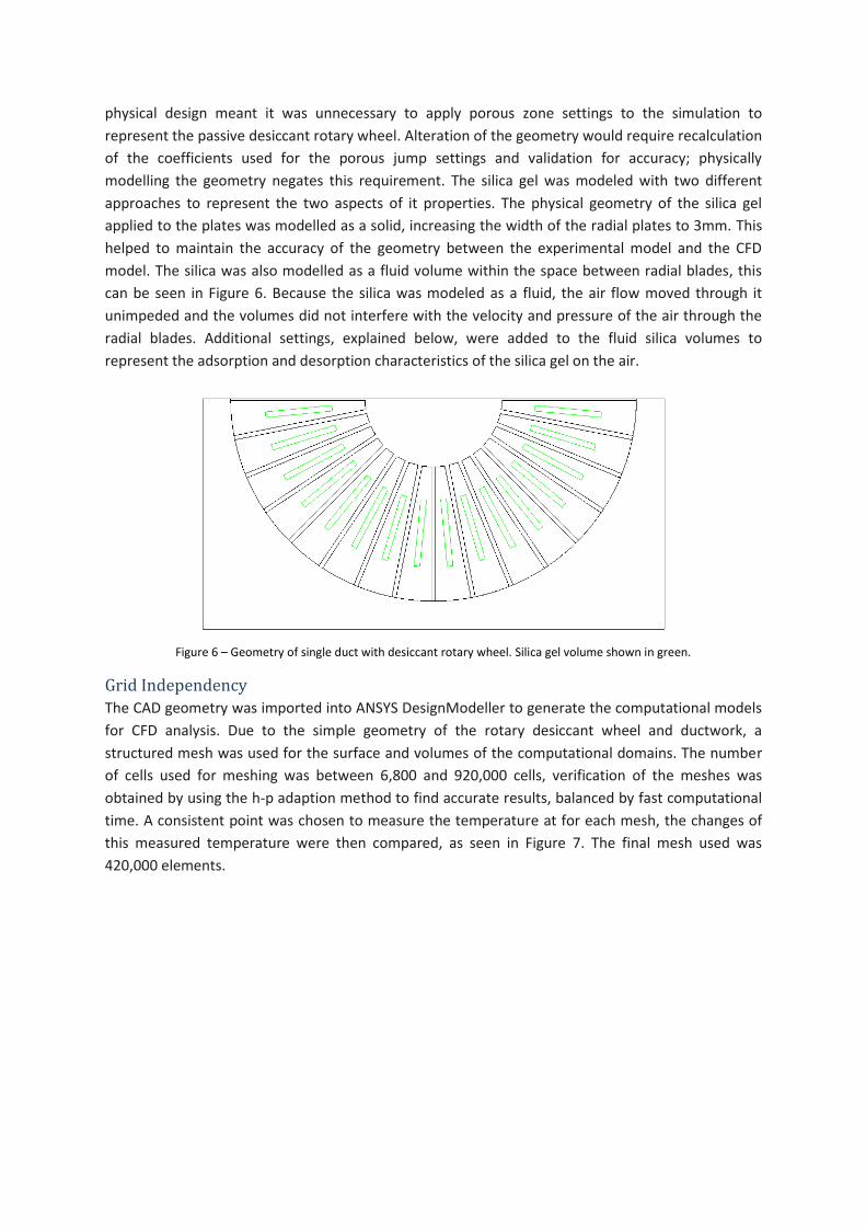
modelling the geometry negates this requirement. The silica gel was modeled with two different
approaches to represent the two aspects of it properties. The physical geometry of the silica gel
applied to the plates was modelled as a solid, increasing the width of the radial plates to 3mm. This
helped to maintain the accuracy of the geometry between the experimental model and the CFD
model. The silica was also modelled as a fluid volume within the space between radial blades, this
can be seen in Figure 6. Because the silica was modeled as a fluid, the air flow moved through it
unimpeded and the volumes did not interfere with the velocity and pressure of the air through the
radial blades. Additional settings, explained below, were added to the fluid silica volumes to
represent the adsorption and desorption characteristics of the silica gel on the air.
Figure 6 に Geometry of single duct with desiccant rotary wheel. Silica gel volume shown in green.
Grid Independency
The CAD geometry was imported into ANSYS DesignModeller to generate the computational models
for CFD analysis. Due to the simple geometry of the rotary desiccant wheel and ductwork, a
structured mesh was used for the surface and volumes of the computational domains. The number
of cells used for meshing was between 6,800 and 920,000 cells, verification of the meshes was
obtained by using the h-p adaption method to find accurate results, balanced by fast computational
time. A consistent point was chosen to measure the temperature at for each mesh, the changes of
this measured temperature were then compared, as seen in Figure 7. The final mesh used was
420,000 elements.
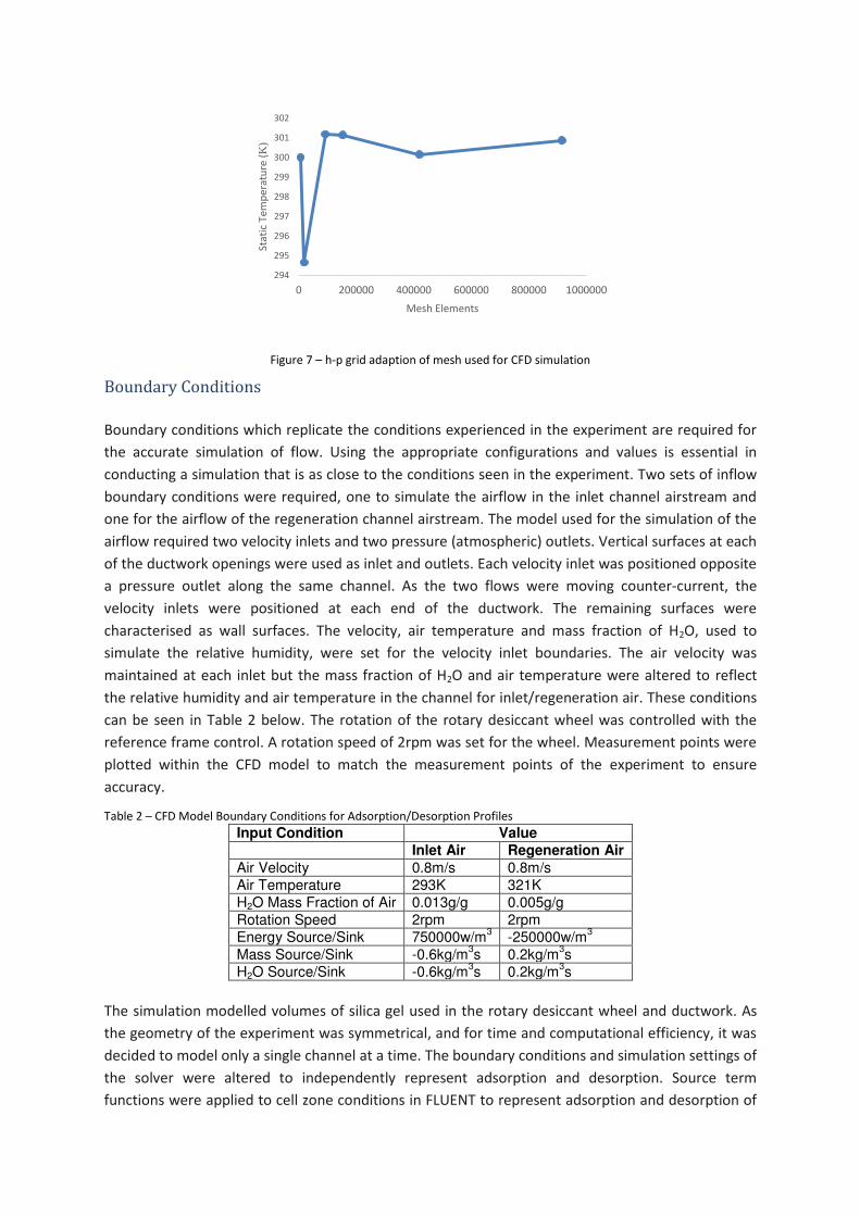
Figure 7 に h-p grid adaption of mesh used for CFD simulation
Boundary Conditions
Boundary conditions which replicate the conditions experienced in the experiment are required for
the accurate simulation of flow. Using the appropriate configurations and values is essential in
conducting a simulation that is as close to the conditions seen in the experiment. Two sets of inflow
boundary conditions were required, one to simulate the airflow in the inlet channel airstream and
one for the airflow of the regeneration channel airstream. The model used for the simulation of the
airflow required two velocity inlets and two pressure (atmospheric) outlets. Vertical surfaces at each
of the ductwork openings were used as inlet and outlets. Each velocity inlet was positioned opposite
a pressure outlet along the same channel. As the two flows were moving counter-current, the
velocity inlets were positioned at each end of the ductwork. The remaining surfaces were
characterised as wall surfaces. The velocity, air temperature and mass fraction of H2O, used to
simulate the relative humidity, were set for the velocity inlet boundaries. The air velocity was
maintained at each inlet but the mass fraction of H2O and air temperature were altered to reflect
the relative humidity and air temperature in the channel for inlet/regeneration air. These conditions
can be seen in Table 2 below. The rotation of the rotary desiccant wheel was controlled with the
reference frame control. A rotation speed of 2rpm was set for the wheel. Measurement points were
plotted within the CFD model to match the measurement points of the experiment to ensure
accuracy.
Table 2 に CFD Model Boundary Conditions for Adsorption/Desorption Profiles
Input Condition Value
Inlet Air Regeneration Air
Air Velocity 0.8m/s 0.8m/s
Air Temperature 293K 321K
H2O Mass Fraction of Air 0.013g/g 0.005g/g
Rotation Speed 2rpm 2rpm
Energy Source/Sink 750000w/m3 -250000w/m
3
Mass Source/Sink -0.6kg/m3s 0.2kg/m
3s
H2O Source/Sink -0.6kg/m3s 0.2kg/m
3s
The simulation modelled volumes of silica gel used in the rotary desiccant wheel and ductwork. As
the geometry of the experiment was symmetrical, and for time and computational efficiency, it was
decided to model only a single channel at a time. The boundary conditions and simulation settings of
the solver were altered to independently represent adsorption and desorption. Source term
functions were applied to cell zone conditions in FLUENT to represent adsorption and desorption of
294
295
296
297
298
299
300
301
302
0 200000 400000 600000 800000 1000000
Stat
ic T
em
pe
ratu
re (K
)
Mesh Elements
the silica gel. The material properties of silica gel were applied to the fluid volume, using sink/source
(s/s) terms for adsorption/desorption (a/d) respectively. S/s terms are used to add and remove
characteristics of the fluid flow, such as energy, mass, species and momentum, at a predetermined
rate. Energy, mass and species terms are required for a/d and were set for the characteristics of the
silica gel. The solver requires the same s/s values for mass and species to be set as inputs to ensure
calculation stability. Energy s/s terms are used for the increase or decrease in dry bulb temperature,
the change in temperature occurring as a result of a/d processes. The values for the s/s terms can be
seen above in Table 2.
Validation of CFD Model
Comparison of the values measured in the experiment and the values measured from the CFD
models is necessary for validation of the CFD models to confirm their accuracy and reliability for
future modelling. Values of air temperature and relative humidity were measured from the CFD
simulations at the same position as the experiment for accuracy.
Table 3 shows the comparison between values calculated from the CFD simulations and the
measurements taken from the 600 second time step of the experiment. The error between the CFD
results and the experimental data is included for comparison and validation.
Table 3 に Comparison and Validation of CFD model using Experimental Results
TEMPERATURE (°C) RELATIVE HUMIDITY (%)
Before Wheel After Wheel Before Wheel After Wheel
ADSORPTION CFD 20.00 27.14 90.70 33.14
Experiment 20.11 27.46 91.28 27.46
Error % 0.55 1.17 0.64 -20.68
DESORPTION CFD 48.00 45.54 7.32 11.45
Experiment 49.68 45.29 6.60 10.23
Error % 3.38 -0.55 -10.91 -11.93
The error between the CFD and experiment data for the temperature readings is lower than the
relative humidity readings. As the air temperature for the inlet boundary conditions can be set
precisely, this is not unexpected for the readings before the wheel. The low error between the
temperature readings for both the adsorption and desorption cases after the wheel however show
greater accuracy and reliability between the two methodologies. Higher errors are introduced for
the relative humidity readings for both cases with the CFD simulations consistently overestimating
the relative humidity when compared to the experimental data. However, the degree to which the
error is increased is notable due to the lower initial values of the data. As the values are small,
differences of 0.72rH% and 1.22rH% between the two readings are more pronounced when
computed as a percentage of the total value. The CFD models provide a credible method of
analysing the new design of desiccant wheel which could be further improved by refinement of the
boundary conditions and solver settings.
Results and Discussion
Air temperature and Relative Humidity
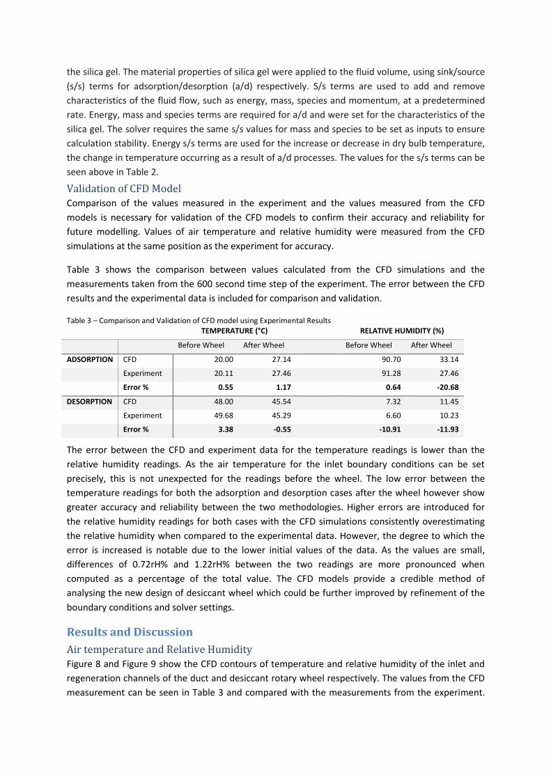
Figure 8 and Figure 9 show the CFD contours of temperature and relative humidity of the inlet and
regeneration channels of the duct and desiccant rotary wheel respectively. The values from the CFD
measurement can be seen in Table 3 and compared with the measurements from the experiment.
Good agreement between the experiment values and CFD values were seen for both the air
temperature and relative humidity.
Figure 8 に Contours of a) temperature (in K) and b) relative humidity (%) for the CFD model of the inlet air channel
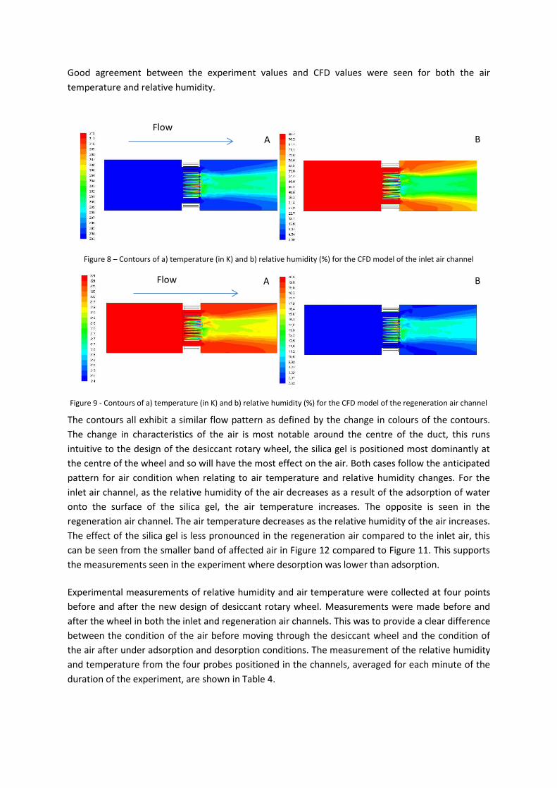
Figure 9 - Contours of a) temperature (in K) and b) relative humidity (%) for the CFD model of the regeneration air channel
The contours all exhibit a similar flow pattern as defined by the change in colours of the contours.
The change in characteristics of the air is most notable around the centre of the duct, this runs
intuitive to the design of the desiccant rotary wheel, the silica gel is positioned most dominantly at
the centre of the wheel and so will have the most effect on the air. Both cases follow the anticipated
pattern for air condition when relating to air temperature and relative humidity changes. For the
inlet air channel, as the relative humidity of the air decreases as a result of the adsorption of water
onto the surface of the silica gel, the air temperature increases. The opposite is seen in the
regeneration air channel. The air temperature decreases as the relative humidity of the air increases.
The effect of the silica gel is less pronounced in the regeneration air compared to the inlet air, this
can be seen from the smaller band of affected air in Figure 12 compared to Figure 11. This supports
the measurements seen in the experiment where desorption was lower than adsorption.
Experimental measurements of relative humidity and air temperature were collected at four points
before and after the new design of desiccant rotary wheel. Measurements were made before and
after the wheel in both the inlet and regeneration air channels. This was to provide a clear difference
between the condition of the air before moving through the desiccant wheel and the condition of
the air after under adsorption and desorption conditions. The measurement of the relative humidity
and temperature from the four probes positioned in the channels, averaged for each minute of the
duration of the experiment, are shown in Table 4.
Flow B
B A
A
Flow
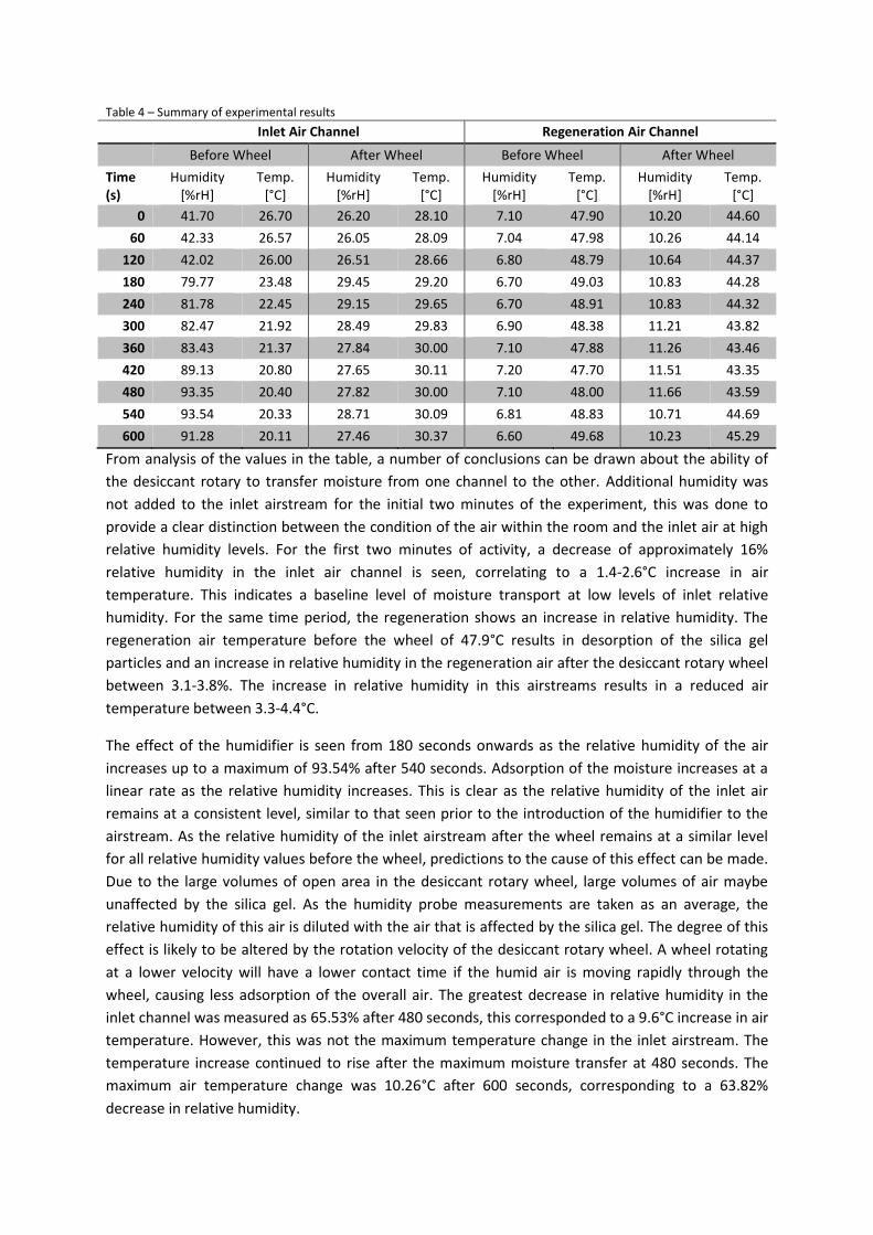
Table 4 に Summary of experimental results
Inlet Air Channel Regeneration Air Channel
Before Wheel After Wheel Before Wheel After Wheel
Time
(s)
Humidity
[%rH]
Temp.
[°C]
Humidity
[%rH]
Temp.
[°C]
Humidity
[%rH]
Temp.
[°C]
Humidity
[%rH]
Temp.
[°C]
0 41.70 26.70 26.20 28.10 7.10 47.90 10.20 44.60
60 42.33 26.57 26.05 28.09 7.04 47.98 10.26 44.14
120 42.02 26.00 26.51 28.66 6.80 48.79 10.64 44.37
180 79.77 23.48 29.45 29.20 6.70 49.03 10.83 44.28
240 81.78 22.45 29.15 29.65 6.70 48.91 10.83 44.32
300 82.47 21.92 28.49 29.83 6.90 48.38 11.21 43.82
360 83.43 21.37 27.84 30.00 7.10 47.88 11.26 43.46
420 89.13 20.80 27.65 30.11 7.20 47.70 11.51 43.35
480 93.35 20.40 27.82 30.00 7.10 48.00 11.66 43.59
540 93.54 20.33 28.71 30.09 6.81 48.83 10.71 44.69
600 91.28 20.11 27.46 30.37 6.60 49.68 10.23 45.29
From analysis of the values in the table, a number of conclusions can be drawn about the ability of
the desiccant rotary to transfer moisture from one channel to the other. Additional humidity was
not added to the inlet airstream for the initial two minutes of the experiment, this was done to
provide a clear distinction between the condition of the air within the room and the inlet air at high
relative humidity levels. For the first two minutes of activity, a decrease of approximately 16%
relative humidity in the inlet air channel is seen, correlating to a 1.4-2.6°C increase in air
temperature. This indicates a baseline level of moisture transport at low levels of inlet relative
humidity. For the same time period, the regeneration shows an increase in relative humidity. The
regeneration air temperature before the wheel of 47.9°C results in desorption of the silica gel
particles and an increase in relative humidity in the regeneration air after the desiccant rotary wheel
between 3.1-3.8%. The increase in relative humidity in this airstreams results in a reduced air
temperature between 3.3-4.4°C.
The effect of the humidifier is seen from 180 seconds onwards as the relative humidity of the air
increases up to a maximum of 93.54% after 540 seconds. Adsorption of the moisture increases at a
linear rate as the relative humidity increases. This is clear as the relative humidity of the inlet air
remains at a consistent level, similar to that seen prior to the introduction of the humidifier to the
airstream. As the relative humidity of the inlet airstream after the wheel remains at a similar level
for all relative humidity values before the wheel, predictions to the cause of this effect can be made.
Due to the large volumes of open area in the desiccant rotary wheel, large volumes of air maybe
unaffected by the silica gel. As the humidity probe measurements are taken as an average, the
relative humidity of this air is diluted with the air that is affected by the silica gel. The degree of this
effect is likely to be altered by the rotation velocity of the desiccant rotary wheel. A wheel rotating
at a lower velocity will have a lower contact time if the humid air is moving rapidly through the
wheel, causing less adsorption of the overall air. The greatest decrease in relative humidity in the
inlet channel was measured as 65.53% after 480 seconds, this corresponded to a 9.6°C increase in air
temperature. However, this was not the maximum temperature change in the inlet airstream. The
temperature increase continued to rise after the maximum moisture transfer at 480 seconds. The
maximum air temperature change was 10.26°C after 600 seconds, corresponding to a 63.82%
decrease in relative humidity.
The disparity between the maximum relative humidity value, the maximum relative humidity change
and the maximum temperature change in the inlet airstream is unexpected but can be explained.
The maximum relative humidity value, measured at 540 seconds, is marginally higher than the
relative humidity measured at 480 seconds when the maximum relative humidity change is
measured. That the maximum change occurs at the time step before the maximum value is
measured suggests that the silica gel particle may have become saturated and are no longer able to
adsorb a greater volume of moisture. This provides a possible explanation between the discrepancy
of the time step where the maximum relative humidity is measured and the maximum change. The
maximum air temperature change is measured at the final experiment time step, when the probe
will have experienced the maximum exposure time to the airstream, continually increasing the
temperature of the probe. This is an important consideration as the probe uses a metallic hotwire to
measure the air temperature. Continued exposure to the increasing air temperature will result in a
lag time in the hotwire when a lower air temperature is introduced.
The change in relative humidity in the regeneration air channel reaches a peak value of 4.56%, also
at 480 seconds. This suggests that as the maximum adsorption levels are reached by the silica gel
particles, the maximum desorption rate is also experienced. This is as expected as the silica gel
particles contain the highest volume of water available to be desorbed. The greatest air temperature
change between the two measurement locations is at 180 seconds, the time when the effect of the
introduction of the humidifier can be most clearly seen. The maximum air temperature reduction of
4.75°C at 180 seconds decreases to a minimum value of 4.14°C at 540 seconds. Though potentially
surprising, this does follow the precedent shown in earlier results. The air temperature change at
540 seconds corresponds to a 3.90% increase in relative humidity. Earlier in the test, at 120 seconds,
a 3.84% increase in relative humidity corresponded to a 4.42°C decrease in air temperature. This
shows that though the values of relative humidity increase and air temperature decrease are
correlated, they are not a predictable pattern. Two separate instances of equal relative humidity
change result in different air temperature increase, 180 seconds and 240 seconds both show a 4.13%
increase in relative humidity but a 4.75°C and 4.59°C decrease in air temperature respectively. At
both 300 and 400 seconds, a 4.31% increase in relative humidity is measured but a 4.56°C and
4.35°C decrease in air temperature respectively. The difference between the two temperature
decrease values is small, and so it is worth considering the accuracy of the measurement equipment
as a cause of the apparent anomalies.
It is important to note that the regeneration air temperature, used for desorption of the water
molecules from the silica gel particles, before the desiccant rotary wheel was 48.5°C. This represents
a significant reduction in the regeneration air temperature previously used for desorption in rotary
desiccant wheels. The regeneration air temperature is achieved by increasing the temperature of
low-grade waste air, typically exhaust air from mechanical processes, using electric heaters. This has
high energy costs by increasing the air temperature to 80-120°C. By showing that desorption can be
achieved at significantly lower regeneration temperatures, the associated energy costs can be
lowered or removed from the dehumidification process. This enhances the prospect of the desiccant
rotary wheel with radial blades configuration.
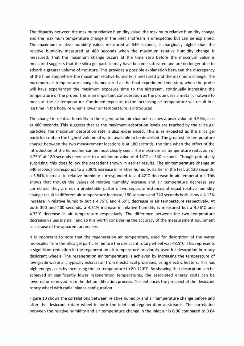
Figure 10 shows the correlations between relative humidity and air temperature change before and
after the desiccant rotary wheel in both the inlet and regeneration airstreams. The correlation
between the relative humidity and air temperature change in the inlet air is 0.96 compared to 0.64
for the regeneration air. This shows that the influence of one of the factors on the other is
significantly greater in the inlet air than the regeneration air.
Figure 10 に Correlation between Humidity Change and Air Temperature Change in a) Inlet Air and b) Regeneration Air
The increased correlation in the inlet air compared to the regeneration air is likely due to a
combination of reasons. The changes in relative humidity and air temperature measured in the
regeneration air are generally of a lower value than the changes measured in the inlet air. Therefore,
errors and deviation from the mean seen in the regeneration air have a greater effect in reducing
the correlation of relative humidity and air temperature change.
Pressure Drop across Desiccant Rotary Wheel
In addition to the changes in air temperature and relative humidity affected by the new design of the
desiccant rotary wheel, the pressure drop measured before and after the wheel is of importance. As
current desiccant rotary wheels exhibit a high pressure drop in the air flow, the integration of these
devices into ventilation systems requires additional equipment to circulate air and are unsuitable for
natural ventilation systems. Minimising the pressure drop with the new design of the desiccant
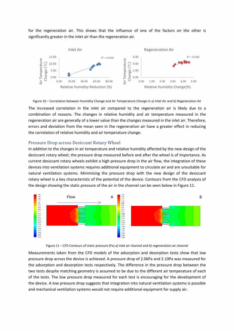
rotary wheel is a key characteristic of the potential of the device. Contours from the CFD analysis of
the design showing the static pressure of the air in the channel can be seen below in Figure 11.
Figure 11 に CFD Contours of static pressure (Pa) a) inlet air channel and b) regeneration air channel
Measurements taken from the CFD models of the adsorption and desorption tests show that low
pressure drop across the device is achieved. A pressure drop of 2.06Pa and 2.10Pa was measured for
the adsorption and desorption tests respectively. The difference in the pressure drop between the
two tests despite matching geometry is assumed to be due to the different air temperature of each
of the tests. The low pressure drop measured for each test is encouraging for the development of
the device. A low pressure drop suggests that integration into natural ventilation systems is possible
and mechanical ventilation systems would not require additional equipment for supply air.
R² = 0.9586
0.00
5.00
10.00
15.00
0.00 20.00 40.00 60.00 80.00
Air
Te
mp
era
ture
Ch
ange
(°C
)
Relative Humidity Reduction (%)
Inlet Air
R² = 0.6384
0.00
2.00
4.00
6.00
0.00 1.00 2.00 3.00 4.00 5.00
Air
Te
mp
era
ture
Ch
ange
(°C
)
Relative Humidity Change(%)
Regeneration Air
B A Flow
The goal of limiting the pressure drop is to ensure that the velocity of the air moving through the
desiccant rotary wheel, particularly in the inlet air channel, remains high enough to provide
adequate air supply rates for possible integration into passive ventilation systems. To do this, a
pressure drop no greater than 2Pa was viewed as acceptable. Because of the low air velocities of
passive ventilation systems, a pressure drop greater than this would result in very low air supply
rates, this has been confirmed in early work on passive ventilation systems [45].
Equation 1 ଵ ͳʹ ߩ ଵܸଶ ݄݃ߩ ൌ ଶ ͳʹ ߩ ଶܸଶ ݄݃ߩ
It can be seen from studying the Bernoulli Equation in Equation 1, that the balance between
pressure and velocity before the wheel and after the wheel must be maintained for a fluid. As can be
seen in Figure 11, the pressure before the wheel is higher than the pressure after the wheel in both
cases. Because of the reduction in pressure, air velocity after the wheel must increase to provide
balance to the Bernoulli Equation. It was shown in the CFD analysis that the velocity before the
wheel was 0.85m/s for both conditions and 1.65m/s and 1.64m/s for the adsorption and desorption
respectively. This remains consistent with the Bernoulli Equation. The contraction of the air flow
through the wheel will result in acceleration of the air as it passes through. The results further
highlight the benefit of the new design for the rotary desiccant wheel in reducing pressure without
affecting the air velocity, providing evidence for integration into passive ventilation systems with
further investigation.
Only a single alternative design of matrix structure has been tested in this work, further work would
seek to explore more designs. Increased/decreased number of blades, optimised size of blades and
the silica gel particles, alternative matrix designs in a concentric circle or similar arrangement, a
range of inlet/regeneration air temperatures, relative humidity and air velocities can all be tested to
improve the experimental testing.
Conclusion
The ability of a new design of desiccant rotary wheel with 28 silica gel coated radial blades to reduce
the relative humidity of an airstream and the pressure drop across the wheel was tested
experimentally using a prototype setup and validated a CFD simulation. Adsorption of moisture in
the inlet airstream up to 65% was noted whilst increasing the air temperature of the inlet air by
9.6°C. Furthermore, constant regeneration of the desiccant material was achieved at a regeneration
temperature of 48.5°C, significantly lower than regeneration temperatures commonly used in
desiccant systems. The pressure drop across the desiccant rotary wheel was measured as 2.06Pa,
lower than the pressure drop across the matrix of traditional desiccant rotary wheel designs.
The results from the CFD analysis and experiments show that the new design of the desiccant rotary
wheel has many potentials that could help to significantly improve the condition of incoming air, as
well as reduce energy demand for building operators. The proposed arrangement of silica gel
particles on the surface of the blades show high adsorption of water from the air, which is able to be
regenerated. Lowering the relative humidity of the air aids in the conditioning of air for improved
thermal comfort to occupants. The regeneration temperature required is significantly lower than the
temperature previously used in desiccant systems. This provides some evidence that lower
regeneration temperatures may be used for desorption of the silica gel and so provide a reduction in
the total energy use of the system.
As this experiment ran for a comparatively short time, an estimation of the energy saved was not
made. Prolonged running of the experiment would be beneficial to ensure that the operation of the
wheel is suitable beyond a running time of 10 minutes. As operations of desiccant wheels can be up
to 24 hours per day, it will be necessary to ensure if complete saturation of the silica gel particles is
possible and if the continuous desorption process is adequate to prevent this situation. Full
integration of the device into mechanical and natural ventilation systems would provide a useful
comparison of air quality, supply rates and energy consumption, between each other and with
existing systems.
As the pressure drop across the wheel has been reduced, the need for additional blowers and fans
commonly used in mechanical systems are not required, it is likely that sufficient supply air can be
generated. This further reduces the energy requirements of the system. As the pressure drop is
approximately 2Pa, the integration of this device into natural ventilation systems is possible. These
systems require no energy for ventilation, enhancing the low energy characteristics of the device.
The results of this work show that an alternative design of desiccant rotary wheels from the
conventional honeycomb/sinusoidal wave structure is capable of reducing the relative humidity of
an incoming airstream with a lower regeneration air temperature and a lower pressure drop
experienced by the airstream. Despite the successes of the design, significant more areas of research
and optimisation are required.
Acknowledgements
The authors of this paper would like to acknowledge the support of The University of Leeds Civil
Engineering department and the support of The University of Sheffield Mechanical Engineering
department. The work presented in this paper is covered by the UK patent GB1506768.9.
References
[1] A.M. Omer, Renewable building energy systems and passive human comfort solutions,
Renew. Sustain. Energy Rev. 12 (2008) 1562に1587. doi:10.1016/j.rser.2006.07.010.
[2] R. Parameshwaran, S. Kalaiselvam, S. Harikrishnan, A. Elayaperumal, Sustainable thermal WミWヴェ┞ ゲデラヴ;ェW デWIエミラノラェキWゲ aラヴ H┌キノSキミェゲ票ぎ A ヴW┗キW┘が RWミW┘く “┌ゲデ;キミく EミWヴェ┞ RW┗く ヱヶ ふヲヰヱヲぶ 2394に2433. doi:10.1016/j.rser.2012.01.058.
[3] Y. El Fouih, P. Stabat, P. Rivière, P. Hoang, V. Archambault, Adequacy of air-to-air heat recovery ventilation system applied in low energy buildings, Energy Build. 54 (2012) 29に39.
doi:10.1016/j.enbuild.2012.08.008.
[4] A. Boyano, P. Hernandez, O. Wolf, Energy demands and potential savings in European office buildings: Case studies based on EnergyPlus simulations, Energy Build. 65 (2013) 19に28.
doi:10.1016/j.enbuild.2013.05.039.
[5] J. Laverge, A. Janssens, Heat recovery ventilation operation traded off against natural and simple exhaust ventilation in Europe by primary energy factor, carbon dioxide emission, household consumer price and exergy, Energy Build. 50 (2012) 315に323.
doi:10.1016/j.enbuild.2012.04.005.
[6] L.Z. Zhang, D.S. Zhu, X.H. Deng, B. Hua, Thermodynamic modeling of a novel air
dehumidification system, 37 (2005) 279に286. doi:10.1016/j.enbuild.2004.06.019.
[7] B. Givoni, Indoor temperature reduction by passive cooling systems, Sol. Energy. 85 (2011)
1692に1726. doi:10.1016/j.solener.2009.10.003.
[8] Pく M;┣┣Wキが Fく MキミキIエキWノノラが Dく P;ノマ;が HVAC SWエ┌マキSキaキI;デキラミ ゲ┞ゲデWマゲ aラヴ デエWヴマ;ノ Iラマaラヴデ票ぎ ; critical review, 25 (2005) 677に707. doi:10.1016/j.applthermaleng.2004.07.014.
[9] S.B. Riffat, M.C. Gillott, Performance of a novel mechanical ventilation heat recovery heat
pump system, Appl. Therm. Eng. 22 (2002) 839に845.
[10] N.C.L. Brum, Modeling and simulation of heat and enthalpy recovery wheels, Energy. 34
(2009) 2063に2068. doi:10.1016/j.energy.2008.08.016.
[11] T.S. Ge, Y. Li, R.Z.Ã. Wang, Y.J. Dai, A review of the mathematical models for predicting rotary
desiccant wheel, 12 (2008) 1485に1528. doi:10.1016/j.rser.2007.01.012.
[12] Y. Tashiro, M. Kubo, Y. Katsumi, T. Meguro, K. Komeya, Assessment of adsorption-desorption characteristics of adsorbents for adsorptive desiccant cooling system, J. Mater. Sci. 39 (2004)
1315に1319. doi:10.1023/B:JMSC.0000013937.11959.6a.
[13] C.X. Jia, Y.J. Dai, J.Y. Wu, R.Z. Wang, Experimental comparison of two honeycombed desiccant wheels fabricated with silica gel and composite desiccant material, Energy Convers. Manag.
47 (2006) 2523に2534. doi:10.1016/j.enconman.2005.10.034.
[14] J.L. Niu, L.Z. Zhang, Membrane-H;ゲWS Eミデエ;ノヮ┞ E┝Iエ;ミェWヴ票ぎ マ;デWヴキ;ノ IラミゲキSWヴ;デキラミゲ ;ミS clarification of moisture resistance, J. Memb. Sci. 189 (2001) 179に191.
[15] G. Angrisani, F. Minichiello, C. Roselli, M. Sasso, Experimental analysis on the dehumidification and thermal performance of a desiccant wheel, Appl. Energy. 92 (2012)
563に572. doi:10.1016/j.apenergy.2011.11.071.
[16] J. Taweekun, V. Akvanich, The Experiment and Simulation of Solid Desiccant Dehumidification
for Air-Conditioning System in a Tropical Humid Climate, Engineering. 2013 (2013) 146に153.
[17] A. Mardiana, S.B. Riffat, Review on physical and performance parameters of heat recovery systems for building applications, Renew. Sustain. Energy Rev. 28 (2013) 174に190.
doi:10.1016/j.rser.2013.07.016.
[18] L.Z. Zhang, J.L. Niu, Performance comparisons of desiccant wheels for air dehumidification
and enthalpy recovery, 22 (2002) 1347に1367.
[19] D.G. Waugaman, A. Kini, C.F. Kettleborough, A Review of Desiccant Cooling Systems, J. Energy
Resour. Technol. 115 (1993) 1. doi:10.1115/1.2905965.
[20] C. Roulet, F.D. Heidt, F. Foradini, M. Pibiri, Real heat recovery with air handling units, 33
(2001) 495に502.
[21] G. Angrisani, C. Roselli, M. Sasso, Experimental assessment of the energy performance of a hybrid desiccant cooling system and comparison with other air-conditioning technologies,
Appl. Energy. 138 (2015) 533に545. doi:10.1016/j.apenergy.2014.10.065.
[22] X.J. Zhang, Y.J. Dai, R.Z. Wang, A simulation study of heat and mass transfer in a
honeycombed rotary desiccant dehumidifier, 23 (2003) 989に1003. doi:10.1016/S1359-
4311(03)00047-4.
[23] N. Enteria, H. Yoshino, A. Satake, A. Mochida, R. Takaki, R. Yoshie, et al., Experimental heat and mass transfer of the separated and coupled rotating desiccant wheel and heat wheel,
Exp. Therm. Fluid Sci. 34 (2010) 603に615. doi:10.1016/j.expthermflusci.2009.12.001.
[24] Y. Fan, K. Ito, Energy consumption analysis intended for real office space with energy recovery ventilator by integrating BES and CFD approaches, Build. Environ. 52 (2012) 57に67.
doi:10.1016/j.buildenv.2011.12.008.
[25] M. Intini, S. De Antonellis, C.M. Joppolo, The effect of inlet velocity and unbalanced flows on optimal working conditions of silica gel desiccant wheels, Energy Procedia. 48 (2014) 858に864. doi:10.1016/j.egypro.2014.02.099.
[26] K. Keniar, K. Ghali, N. Ghaddar, Study of solar regenerated membrane desiccant system to
control humidity and decrease energy consumption in office spaces, Appl. Energy. 138 (2015)
121に132. doi:10.1016/j.apenergy.2014.10.071.
[27] B.R. Hughes, J.K. Calautit, S.A. Ghani, The development of commercial wind towers for natural ventilation: A review, Appl. Energy. 92 (2012) 606に627.
doi:10.1016/j.apenergy.2011.11.066.
[28] B.R. Hughes, C.M. Mak, A study of wind and buoyancy driven flows through commercial wind
towers, Energy Build. 43 (2011) 1784に1791. doi:10.1016/j.enbuild.2011.03.022.
[29] D. Mumovic, J. Palmer, M. Davies, M. Orme, I. Ridley, T. Oreszczyn, et al., Winter indoor air quality, thermal comfort and acoustic performance of newly built secondary schools in
England, Build. Environ. 44 (2009) 1466に1477. doi:10.1016/j.buildenv.2008.06.014.
[30] M. Kolokotroni, B.C. Webb, S.D. Hayes, Summer cooling with night ventilation for office buildings in moderate climates, Energy Build. 27 (1998) 231に237. doi:10.1016/S0378-
7788(97)00048-0.
[31] D.J. Clements-Croome, H.B. Awbi, Z. Bak??-Bir??, N. Kochhar, M. Williams, Ventilation rates in
schools, Build. Environ. 43 (2008) 362に367. doi:10.1016/j.buildenv.2006.03.018.
[32] A.W. Woods, S. Fitzgerald, S. Livermore, A comparison of winter pre-heating requirements for natural displacement and natural mixing ventilation, Energy Build. 41 (2009) 1306に1312.
doi:10.1016/j.enbuild.2009.07.030.
[33] Health and Safety Executive, Workplace health, safety and welfare, (2013) 19.
[34] Dく OげCラミミラヴが JくKく C;ノ;┌デキデが BくRく H┌ェエWゲが A ゲデ┌S┞ ラa ヮ;ゲゲキ┗W ┗Wミデキノ;デキラミ キミデWェrated with heat
recovery, Energy Build. 82 (2014) 799に811. doi:10.1016/j.enbuild.2014.05.050.
[35] A. Mardiana, S.B. Riffat, M. Worall, Integrated heat recovery system with wind-catcher for
H┌キノSキミェ ;ヮヮノキI;デキラミゲ票ぎ デラ┘;ヴSゲ WミWヴェ┞-efficient technologies, Mater. Process. Energy
Commun. Curr. Res. Tech. Dev. (2013) 720に727.
[36] J.K. Calautit, H.N. Chaudhry, B.R. Hughes, S.A. Ghani, Comparison between evaporative cooling and a heat pipe assisted thermal loop for a commercial wind tower in hot and dry
climatic conditions, Appl. Energy. 101 (2013) 740に755. doi:10.1016/j.apenergy.2012.07.034.
[37] S. Soutullo, C. Sanjuan, M.R. Heras, Energy performance evaluation of an evaporative wind
tower, Sol. Energy. 86 (2012) 1396に1410. doi:10.1016/j.solener.2012.02.001.
[38] P. Bourdoukan, E. Wurtz, P. Joubert, M. Spe, Potential of solar heat pipe vacuum collectors in デエW SWゲキII;ミデ Iララノキミェ ヮヴラIWゲゲ票ぎ MラSWノノキミェ ;ミS W┝ヮWヴキマWミデ;ノ ヴWゲ┌ノデゲが Βヲ ふヲヰヰΒぶ ヱヲヰΓに1219.
doi:10.1016/j.solener.2008.06.003.
[39] N. Enteria, H. Yoshino, A. Mochida, R. Takaki, A. Satake, Construction and initial operation of the combined solar thermal and electric desiccant cooling system, Sol. Energy. 83 (2009)
1300に1311. doi:10.1016/j.solener.2009.03.008.
[40] J. Jeong, S. Yamaguchi, K. Saito, S. Kawai, Performance analysis of four-partition desiccant wheel and hybrid dehumidification air-conditioning system ´ shydratante a ` quatre Analyse SW ノ; ヮWヴaラヴマ;ミIW S げ ┌ミW ヴラ┌W SW ╄ マW SW IラミSキデキラミミWマWミデ S げ ;キヴ ; ゲWェマWミデゲ Wデ S げ ┌ミ ゲ┞ゲデW ╉ shydratant hybride d, Int. J. Refrig. 33 (2010) 496に509. doi:10.1016/j.ijrefrig.2009.12.001.
[41] L.Z. Zhang, Energy performance of independent air dehumidification systems with energy
recovery measures, Energy. 31 (2006) 1228に1242. doi:10.1016/j.energy.2005.05.027.
[42] J.K. Calautit, H.N. Chaudhry, B.R. Hughes, L. Sim, A validated design methodology for a closed-loop subsonic wind tunnel, Jnl. Wind Eng. Ind. Aerodyn. 125 (2014) 180に194.
doi:10.1016/j.jweia.2013.12.010.
[43] B.R. Hughes, S.A.A.A. Ghani, A numerical investigation into the effect of Windvent louvre external angle on passive stack ventilation performance, Build. Environ. 45 (2010) 1025に1036. doi:10.1016/j.buildenv.2009.10.010.
[44] ANSYS, ANSYS Fluent Theory Guide, (2013) 814.
[45] L. Shao, S.B. Riffat, G. Gan, Heat recovery with low pressure loss for natural veltilation, Energy
Build. 28 (1998) 179に184. doi:10.1016/S0378-7788(98)00016-4.