Embed Size (px)
Citation preview
Energy Conversion and Management 80 (2014) 63–70
Contents lists available at ScienceDirect
Energy Conversion and Management
journal homepage: www.elsevier .com/ locate /enconman
A real time fuzzy logic power management strategy for a fuel cell vehicle
0196-8904/$ - see front matter � 2014 Elsevier Ltd. All rights reserved.http://dx.doi.org/10.1016/j.enconman.2013.12.040
⇑ Corresponding author at: Université de Moncton, Campus de Moncton, PavillonLéopold-Taillon 18, avenue Antonine-Maillet, Moncton, NB, Canada E1A 3E9.
E-mail addresses: [email protected] (H. Hemi), [email protected] (J. Ghouili), [email protected] (A. Cheriti).
Hanane Hemi a,b,⇑, Jamel Ghouili a, Ahmed Cheriti b
a University of Moncton, Moncton, New Brunswick, Canadab University of Quebec in Trois-Rivieres, Quebec, Canada
a r t i c l e i n f o
Article history:Received 4 July 2013Accepted 17 December 2013Available online 5 February 2014
Keywords:Fuel cell hybrid vehiclePower managementFuzzy logicBatterySupercapacitorFuel cell
a b s t r a c t
This paper presents real time fuzzy logic controller (FLC) approach used to design a power managementstrategy for a hybrid electric vehicle and to protect the battery from overcharging during the repetitivebraking energy accumulation. The fuel cell (FC) and battery (B)/supercapacitor (SC) are the primaryand secondary power sources, respectively. This paper analyzes and evaluates the performance of thethree configurations, FC/B, FC/SC and FC/B/SC during real time driving conditions and unknown drivingcycle. The MATLAB/Simulink and SimPowerSystems software packages are used to model the electricaland mechanical elements of hybrid vehicles and implement a fuzzy logic strategy.
� 2014 Elsevier Ltd. All rights reserved.
1. Introduction
The need to minimize noxious CO2 and greenhouse gas emis-sions has led to an increase in the use of hybrid vehicles in recentyears. These vehicles include thermal hybrid vehicles, electricalvehicles equipped with a battery, and fuel cell hybrid vehicles.
Progress has been made in fuel cell modeling and characteriza-tion, and also in understanding the static converters that interfacewith the fuel cell during charging. Nevertheless, studies of energymanagement and optimization are still at an early stage. It is chal-lenging to develop an energy management strategy for a hybridvehicle supported by a storage device such as a battery or a sup-ercapacitor. Regardless of the route, the available power must bedistributed among the various components to minimize hydrogenutilization and increase lifetime.
Several energy management strategies have been suggested tocontrol the distribution of power between the two sources andthe load. Ref. [1] presents the energy management system basedon an equivalent consumption minimization strategy (ECMS).Ref. [2] develops a real time optimal energy management strategybased on the determined dynamic programming (DDP) strategy.Refs. [3–6] propose a fuzzy logic control system.
Some references have proposed using a fuzzy logic controllerenergy management for fuel cell electrical vehicle. Ref. [3] listssome advantages of this method.
Ref. [3] proposes a fuzzy logic implemented in the ADVISORenvironment for FC/B and FC/B/SC vehicles to improve the fueleconomy and increase the distance traveled. This method resultsin better fuel economy and driving cycle conditions but the batteryor supercapacitor SOC information are not presented in this paper.
The Ref. [4] proposes a fuzzy logic control system for powermanagement and uses a known city driving cycle (UDDS) to deter-mine the optimal fuel cell and battery power on a hybrid bus. Theresults of this proposed method show a good power distributionbetween the mini-bus power sources and the required power. Also,the battery SOC is maintained bounded. In this study, the batterySOC results show that the SOC increases in repetitive brakingduring the latest part of UDDS drive cycle.
Ref. [5] presents a fuzzy logic based control methodology. Thisproposed strategy is based on a priori knowledge of driving cycleto design the degree of hybridization and also membership func-tions of the fuzzy controller using optimization problem witchmaximize fuel cell hybrid vehicle efficiency. The major inconve-nient of this proposed strategy is that it needs a known driving cy-cle, so it is not applied for real time control. This proposed strategyresults is compared using fuzzy logic control with fixed member-ship functions and optimized degree of hybridization. The simula-tion results shows that this proposed strategy improve the systemefficiency, but the optimal degree of hybridization is not sensitiveof different driving cycles.
Ref. [6] introduces the wavelet fuzzy logic strategy to controland distribute the required power from the power sources to theload.
In this paper, the fuzzy logic power management strategy isimplemented in a hybrid vehicle with multiple power sources.
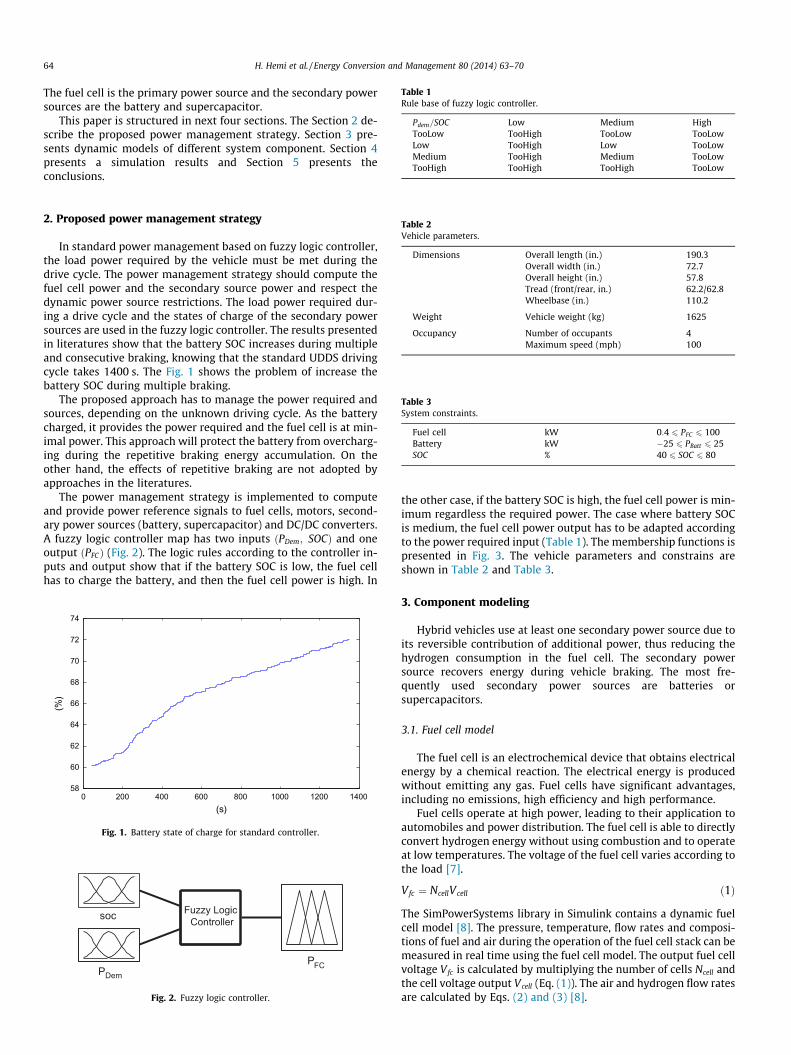
Table 1Rule base of fuzzy logic controller.
Pdem=SOC Low Medium HighTooLow TooHigh TooLow TooLowLow TooHigh Low TooLowMedium TooHigh Medium TooLowTooHigh TooHigh TooHigh TooLow
64 H. Hemi et al. / Energy Conversion and Management 80 (2014) 63–70
The fuel cell is the primary power source and the secondary powersources are the battery and supercapacitor.
This paper is structured in next four sections. The Section 2 de-scribe the proposed power management strategy. Section 3 pre-sents dynamic models of different system component. Section 4presents a simulation results and Section 5 presents theconclusions.
Table 2Vehicle parameters.
Dimensions Overall length (in.) 190.3Overall width (in.) 72.7Overall height (in.) 57.8Tread (front/rear, in.) 62.2/62.8Wheelbase (in.) 110.2
Weight Vehicle weight (kg) 1625
Occupancy Number of occupants 4Maximum speed (mph) 100
Table 3System constraints.
Fuel cell kW 0:4 6 PFC 6 100Battery kW �25 6 PBatt 6 25SOC % 40 6 SOC 6 80
2. Proposed power management strategy
In standard power management based on fuzzy logic controller,the load power required by the vehicle must be met during thedrive cycle. The power management strategy should compute thefuel cell power and the secondary source power and respect thedynamic power source restrictions. The load power required dur-ing a drive cycle and the states of charge of the secondary powersources are used in the fuzzy logic controller. The results presentedin literatures show that the battery SOC increases during multipleand consecutive braking, knowing that the standard UDDS drivingcycle takes 1400 s. The Fig. 1 shows the problem of increase thebattery SOC during multiple braking.
The proposed approach has to manage the power required andsources, depending on the unknown driving cycle. As the batterycharged, it provides the power required and the fuel cell is at min-imal power. This approach will protect the battery from overcharg-ing during the repetitive braking energy accumulation. On theother hand, the effects of repetitive braking are not adopted byapproaches in the literatures.
The power management strategy is implemented to computeand provide power reference signals to fuel cells, motors, second-ary power sources (battery, supercapacitor) and DC/DC converters.A fuzzy logic controller map has two inputs ðPDem; SOCÞ and oneoutput ðPFCÞ (Fig. 2). The logic rules according to the controller in-puts and output show that if the battery SOC is low, the fuel cellhas to charge the battery, and then the fuel cell power is high. In
0 200 400 600 800 1000 1200 140058
60
62
64
66
68
70
72
74
(s)
(%)
Fig. 1. Battery state of charge for standard controller.
soc
PDem
PFC
Fuzzy Logic Controller
Fig. 2. Fuzzy logic controller.
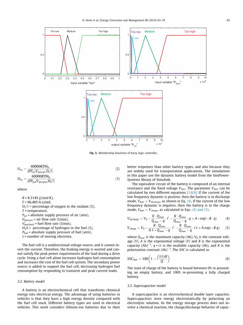
the other case, if the battery SOC is high, the fuel cell power is min-imum regardless the required power. The case where battery SOCis medium, the fuel cell power output has to be adapted accordingto the power required input (Table 1). The membership functions ispresented in Fig. 3. The vehicle parameters and constrains areshown in Table 2 and Table 3.
3. Component modeling
Hybrid vehicles use at least one secondary power source due toits reversible contribution of additional power, thus reducing thehydrogen consumption in the fuel cell. The secondary powersource recovers energy during vehicle braking. The most fre-quently used secondary power sources are batteries orsupercapacitors.
3.1. Fuel cell model
The fuel cell is an electrochemical device that obtains electricalenergy by a chemical reaction. The electrical energy is producedwithout emitting any gas. Fuel cells have significant advantages,including no emissions, high efficiency and high performance.
Fuel cells operate at high power, leading to their application toautomobiles and power distribution. The fuel cell is able to directlyconvert hydrogen energy without using combustion and to operateat low temperatures. The voltage of the fuel cell varies according tothe load [7].
Vfc ¼ NcellVcell ð1Þ
The SimPowerSystems library in Simulink contains a dynamic fuelcell model [8]. The pressure, temperature, flow rates and composi-tions of fuel and air during the operation of the fuel cell stack can bemeasured in real time using the fuel cell model. The output fuel cellvoltage Vfc is calculated by multiplying the number of cells Ncell andthe cell voltage output Vcell (Eq. (1)). The air and hydrogen flow ratesare calculated by Eqs. (2) and (3) [8].
0 0.1 0.2 0.3 0.4 0.5 0.6 0.7 0.8 0.9 1
0
0.5
1
0
0.5
1
0
0.5
1Too low Medium Too high
input variable "soc"
0 1 2 3 4 5 6 7 8 9 10
x 104input variable "PDem"
Medium Too high
Low
Too low
0 1 2 3 4 5 6 7 8 9 10x 104
output variable "PFC"
Medium Too high
Low
Too low
Fig. 3. Membership functions of fuzzy logic controller.
H. Hemi et al. / Energy Conversion and Management 80 (2014) 63–70 65
UO2 ¼60000RTNifc
zFPairV lpmðairÞO2%ð2Þ
UH2 ¼60000RTNifc
zFPfuelV lpmðfuelÞH2%ð3Þ
where
R = 8.3145 j/(mol K),F = 96,485 A s/mol,O2% = percentage of oxygen in the oxidant (%),T = temperature,Pair = absolute supply pressure of air (atm),Vlpm(air) = air flow rate (l/min),Vlpm(fuel) = fuel flow rate (l/min),H2% = percentage of hydrogen in the fuel (%),Pfuel = absolute supply pressure of fuel (atm),z = number of moving electrons.
The fuel cell is a unidirectional voltage source, and it cannot in-vert the current. Therefore, the braking energy is wasted and can-not satisfy the peak power requirements of the load during a drivecycle. Using a fuel cell alone increases hydrogen fuel consumptionand increases the cost of the fuel cell system. The secondary powersource is added to support the fuel cell, decreasing hydrogen fuelconsumption by responding to transient and peak current loads.
3.2. Battery model
A battery is an electrochemical cell that transforms chemicalenergy into electrical energy. The advantage of using batteries invehicles is that they have a high energy density compared withthe fuel cell stack. Different battery types are used in electricalvehicles. This work considers lithium-ion batteries due to their
better responses than other battery types, and also because theyare widely used for transportation applications. The simulationsin this paper use the dynamic battery model from the SimPower-Systems library of Simulink.
The equivalent circuit of the battery is composed of an internalresistance and the fixed voltage VBatt . The parameter VBatt can becalculated by two different equations [1,8,9]. If the current of thelow frequency dynamic is positive, then the battery is in dischargemode, VBatt ¼ Vdischarge, as shown in Eq. (4). If the current of the lowfrequency dynamic is negative, then the battery is in the chargemode, VBatt ¼ Vcharge, as calculated in Eqs. (4) and (5).
Vdischarge ¼ V0 �K � Q max
Q max � q� i� � K � Q max
Qmax � q� qþ A � expð�B � qÞ ð4Þ
Vcharge ¼ V0 �K � Q max
0:1 � Q max � q� i� � K � Q max
Q max � q� i:t þ A:expð�B:qÞ ð5Þ
where Qmax is the maximum capacity (Ah), V0 is the constant volt-age (V), A is the exponential voltage (V) and B is the exponentialcapacity (Ah)�1, q = i.t is the available capacity (Ah), and K is thepolarization constant (Ah)�1. The SOC is calculated as
SOCBatt ¼ 100 1�R
iðtÞdtQ
� �ð6Þ
The state of charge of the battery is bound between 0% re-present-ing an empty battery, and 100% re-presenting a fully chargedbattery.
3.3. Supercapacitor model
A supercapacitor is an electrochemical double layer capacitor.Supercapacitors store energy electrostatically by polarizing anelectrolytic solution. As the energy storage process does not in-volve a chemical reaction, the charge/discharge behavior of capac-

Fig. 4. Supercapacitor model.
66 H. Hemi et al. / Energy Conversion and Management 80 (2014) 63–70
itors is efficient, making supercapacitors ideally suited for pulsepower applications, and also highly reversible, allowing superca-pacitors to be charged and discharged an unlimited number oftimes.
Supercapacitors are able to deliver high currents, and for someapplications are placed in parallel with batteries to assist the bat-teries and extend battery life.
Supercapacitors can be modeled by many equivalent circuitssuch as the popular three slips and ladder circuit models [10].However, it is difficult to construct supercapacitor equivalent cir-cuit due to the complex experiments required to obtain the mod-eling parameters. The classic RC model is simple, and effective,and its parameters can be obtained from datasheets. This articleuses the RC model shown in Fig. 4.
The parameters consist of a very small series resistance ESRwhich is very small, and an ideal capacitor with a capacitance C.This work considers a 16 V, 58 F Maxwell BMOD0058E016B02module [11].
The supercapacitor state of charge (SOC) is defined by thefollowing equation
SOCsc ¼ 100Vsc
Vmax
� �ð%Þ ð7Þ
where Vsc is the supercapacitor voltage and Vmax is the maximumsupercapacitor voltage.
The required voltage and energy or the required capacitance ofthe supercapacitor storage system can be obtained by connectingmultiple supercapacitors in series and parallel. The supercapacitorbank value of the total internal resistance and the total capacitancecan be calculated as in reference [10].
ESRtotal ¼ NsESRsc
Npð8Þ
Ctotal ¼ NpCsc
Nsð9Þ
3.4. Converter configurations
Three hybrid electric vehicle configurations are considered inthis study. The fuel cell is the primary source in all configurations.The secondary source is the battery in the first configuration, thesupercapacitor in the second configuration and the supercapacitorand battery in the last configuration.
In these configurations, a DC/DC converter is connected to theselected power sources. The fuel cell is connected to a unidirec-tional buck converter. The secondary power sources are connectedto a bidirectional buck/boost converter.
The converter configurations are based on a DC bus, which is of-ten used in vehicle converter configurations because of its simplic-ity, low electromagnetic noise emission, and the simplicity ofimplementing the energy and control management subsystem.
3.4.1. FC/B configuration and FC/SC configurationIn this configuration, the system consists of a fuel cell and a sec-
ondary power source (battery or supercapacitor) to provide extrapower and to recover power during braking. The advantages of thisconfiguration include its adaptability for energy control and man-agement and the ability to work at a higher voltage. The FC/B andFC/SC configurations are shown in Fig. 5.
Fig. 5 shows the control loops and the signal generation for thebuck and buck/boost chopper. The power required during a drive iscalculated depending the pedal position. The fuel cell power is de-fined using a fuzzy logic controller. A lookup table is used to calcu-late the required fuel cell current. The battery (supercapacitor)power reference is obtained by subtracting the fuel cell powerreference from the measured required power. The battery (sup-ercapacitor) current reference is obtained by dividing the referencebattery (supercapacitor) power by the measured battery (superca-pacitor) voltage.
A PI controller generates PWM signals from the differences be-tween the reference battery (supercapacitor) current and the bat-tery (supercapacitor) current measured to control the battery(supercapacitor) bidirectional buck/boost converter. The referencecurrent is also used by the fuel cell system to feed the stack withHydrogen and Oxygen.
3.4.2. FC/B/SC configurationThe FC/B/SC configuration is shown in Fig. 6. In this configura-
tion, the system consists of a fuel cell, a battery and a supercapac-itor. This it is a hybrid configuration, with the battery connecteddirectly to the DC bus and the supercapacitor connected to theDC bus via a boost/buck converter. The advantages of this configu-ration are that connecting the supercapacitor increase the batterylife and reduce the battery peak power, which can provide peakpower to the system.
The minimum fuel cell power is defined using two fuzzy logiccontrollers according to the battery and supercapacitor states ofcharge. The battery power is calculated by subtracting the fuel cellpower obtained from the first blok of the fuzzy logic controllerfrom the measured required power. The supercapacitor power isdetermined by subtracting the fuel cell power obtained from thesecond block of the fuzzy logic controller from the measured re-quired power.
The power required for a given supercapacitor state of charge iscalculated supercapacitor states of charge between 50% and 90%.Adding the three calculated powers together yields, the referencesupercapacitor power, which is then divided by the measuredsupercapacitor voltage to obtain the reference battery (superca-pacitor) current.
4. Simulation results and discussion
This paper simulates a hybrid system to analyze and evaluatethe performance of various system configurations proposed duringreal time drive conditions. MATLAB/Simulink software and Sim-PowerSystems are used to model the electrical and mechanical ele-ments of hybrid vehicles. The fuel cell model is from theSimpowerSystem library, and the parameters are from fuel cellsused in Honda Clarity vehicles [12]. The fuel cell is a 400cell,288Vdc , 100 kW Proton Exchange Membrane Fuel Cell (PEMFC).The fuel cell parameters are shown in Table 4. The battery modelis from the SimpowerSystem library. The battery is a 288 V,13.9 Ah, 25 kW lithium-ion battery. The supercapacitor is a288 V, 3.2 F, the supercapacitor, model is presented in Section 3.3.The electric motor is a 288Vdc , 100 kW permanent magnet syn-chronous machine (PMSM). The mechanical model of vehicle is
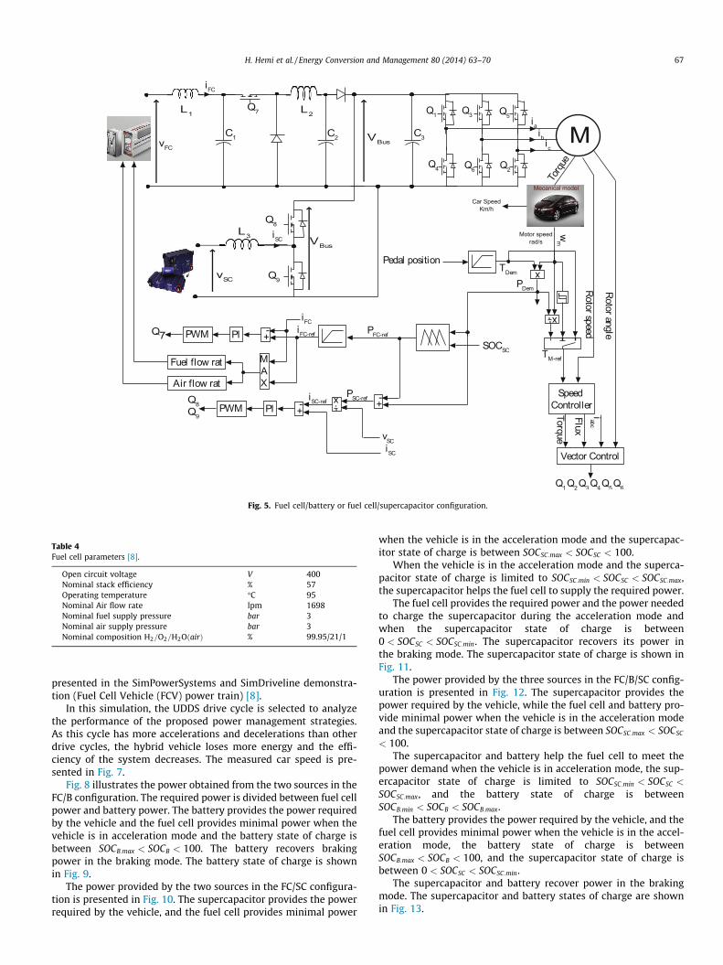
Fig. 5. Fuel cell/battery or fuel cell/supercapacitor configuration.
Table 4Fuel cell parameters [8].
Open circuit voltage V 400Nominal stack efficiency % 57Operating temperature �C 95Nominal Air flow rate lpm 1698Nominal fuel supply pressure bar 3Nominal air supply pressure bar 3Nominal composition H2=O2=H2OðairÞ % 99.95/21/1
H. Hemi et al. / Energy Conversion and Management 80 (2014) 63–70 67
presented in the SimPowerSystems and SimDriveline demonstra-tion (Fuel Cell Vehicle (FCV) power train) [8].
In this simulation, the UDDS drive cycle is selected to analyzethe performance of the proposed power management strategies.As this cycle has more accelerations and decelerations than otherdrive cycles, the hybrid vehicle loses more energy and the effi-ciency of the system decreases. The measured car speed is pre-sented in Fig. 7.
Fig. 8 illustrates the power obtained from the two sources in theFC/B configuration. The required power is divided between fuel cellpower and battery power. The battery provides the power requiredby the vehicle and the fuel cell provides minimal power when thevehicle is in acceleration mode and the battery state of charge isbetween SOCB:max < SOCB < 100. The battery recovers brakingpower in the braking mode. The battery state of charge is shownin Fig. 9.
The power provided by the two sources in the FC/SC configura-tion is presented in Fig. 10. The supercapacitor provides the powerrequired by the vehicle, and the fuel cell provides minimal power
when the vehicle is in the acceleration mode and the supercapac-itor state of charge is between SOCSC:max < SOCSC < 100.
When the vehicle is in the acceleration mode and the superca-pacitor state of charge is limited to SOCSC:min < SOCSC < SOCSC:max,the supercapacitor helps the fuel cell to supply the required power.
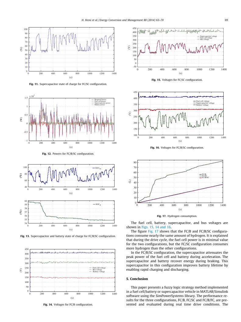
The fuel cell provides the required power and the power neededto charge the supercapacitor during the acceleration mode andwhen the supercapacitor state of charge is between0 < SOCSC < SOCSC:min. The supercapacitor recovers its power inthe braking mode. The supercapacitor state of charge is shown inFig. 11.
The power provided by the three sources in the FC/B/SC config-uration is presented in Fig. 12. The supercapacitor provides thepower required by the vehicle, while the fuel cell and battery pro-vide minimal power when the vehicle is in the acceleration modeand the supercapacitor state of charge is between SOCSC:max < SOCSC
< 100.The supercapacitor and battery help the fuel cell to meet the
power demand when the vehicle is in acceleration mode, the sup-ercapacitor state of charge is limited to SOCSC:min < SOCSC <
SOCSC:max, and the battery state of charge is betweenSOCB:min < SOCB < SOCB:max.
The battery provides the power required by the vehicle, and thefuel cell provides minimal power when the vehicle is in the accel-eration mode, the battery state of charge is betweenSOCB:max < SOCB < 100, and the supercapacitor state of charge isbetween 0 < SOCSC < SOCSC:min.
The supercapacitor and battery recover power in the brakingmode. The supercapacitor and battery states of charge are shownin Fig. 13.
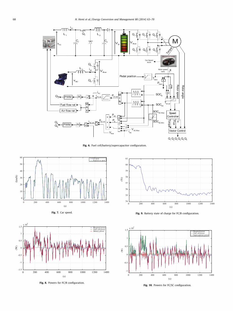
Fig. 6. Fuel cell/battery/supercapacitor configuration.
0 200 400 600 800 1000 1200 1400
0
10
20
30
40
50
60
(s)
(km
/h)
Car speed Required car speed
Fig. 7. Car speed.
0 200 400 600 800 1000 1200 1400-1.5
-1
-0.5
0
0.5
1
1.5x 10
4
(s)
(W)
Required powerFuel cell powerBattery power
Fig. 8. Powers for FC/B configuration.
0 200 400 600 800 1000 1200 140054
55
56
57
58
59
60
61
(s)
(%)
Fig. 9. Battery state of charge for FC/B configuration.
0 200 400 600 800 1000 1200 1400
-1
-0.5
0
0.5
1
1.5x 10
4
(s)
(W)
Required powerFuel cell powerSupercapacitor power
Fig. 10. Powers for FC/SC configuration.
68 H. Hemi et al. / Energy Conversion and Management 80 (2014) 63–70
0 200 400 600 800 1000 1200 14000
10
20
30
40
50
60
70
80
90
100
(s)
(%)
Fig. 11. Supercapacitor state of charge for FC/SC configuration.
0 200 400 600 800 1000 1200 1400-1
-0.5
0
0.5
1
x 104
(s)
(W)
Required powerFuel cell powerSupercapacitor powerBattery power
1.5
Fig. 12. Powers for FC/B/SC configuration.
0 200 400 600 800 1000 1200 140040
60
80
100
(s)
0 200 400 600 800 1000 1200 1400
(s)
54
55
56
57
58
59
60
SOCSC
SOCB
(%)
(%)
Fig. 13. Supercapacitor and battery state of charge for FC/B/SC configuration.
0 200 400 600 800 1000 1200 14000
50
100
150
200
250
300
350
400
450
(s)
(V) Fuel cell voltage
Bus voltageBattery voltage
Fig. 14. Voltages for FC/B configuration.
0 200 400 600 800 1000 1200 1400-50
0
50
100
150
200
250
300
350
400
450
(s)
(V)
Supercapacitor voltageFuel cell voltageBus voltage
Fig. 15. Voltages for FC/SC configuration.
0 200 400 600 800 1000 1200 1400100
150
200
250
300
350
400
450
(s)
(V)
Fuel cell voltageSupercapacitor voltageBattery voltage
Fig. 16. Voltages for FC/B/SC configuration.
0 200 400 600 800 1000 1200 14000
10
20
30
40
50
60
70
80
(s)
(L)
FC/BFC/SCFC/B/SC
Fig. 17. Hydrogen consumption.
H. Hemi et al. / Energy Conversion and Management 80 (2014) 63–70 69
The fuel cell, battery, supercapacitor, and bus voltages areshown in Figs. 15, 14 and 16.
The figure Fig. 17 shows that the FC/B and FC/B/SC configura-tions consume nearly the same amount of hydrogen. It is explainedthat during the drive cycle, the fuel cell power is in minimal valuefor the two configurations, but the FC/SC configuration consumesmore hydrogen than the other configurations.
In the FC/B/SC configuration, the supercapacitor attenuates thepeak power of the fuel cell and battery during acceleration. Thesupercapacitor and battery recover energy during braking. Thissupercapacitor in this configuration improves battery lifetime byenabling rapid charging and discharging.
5. Conclusion
This paper presents a fuzzy logic strategy method implementedin a fuel cell/battery or supercapacitor vehicle in MATLAB/Simulinksoftware using the SimPowerSystems library. The performance re-sults for the three configurations, FC/B, FC/SC and FC/B/FC, are pre-sented and evaluated during real time drive conditions. The
70 H. Hemi et al. / Energy Conversion and Management 80 (2014) 63–70
simulations use the cycle UDDS to evaluate the performance of theproposed strategies because the hybrid vehicle loses more energyin this cycle and exhibits a low system efficiency.
The proposed FLC strategy can satisfy the power requirementfor the unknown driving cycles and achieve the power distributionamong various power source. Also, the results presented show thatrequired power, in acceleration mode, supplied from the battery.Therefore, the proposed FLC controller will offer a novel approachfor a real time power management system of hybrid vehicle. Inaddition, the results indicate that the hydrogen consumption islower for the FC/B and FC/B/SC configurations than for the FC/SCconfiguration. The FC/B/SC configuration improves the batterylifetime by enabling rapid charging and discharging.
References
[1] Garca P, Torreglosa JP, Fernndez LM, et al. Viability study of a FC-battery-SCtramway controlled by equivalent consumption minimization strategy. Int JHydrogen Energy 2012;37:9368–82.
[2] Xu L, Yang F, Li J, et al. Real time optimal energy management strategytargeting at minimizing daily operation cost for a plug-in fuel cell city bus. Int JHydrogen Energy 2012;37:15380–92.
[3] Li Q, Chen W, Li Y, et al. Energy management strategy for fuel cell/battery/ultracapacitor hybrid vehicle based on fuzzy logic. Int J Electr Power EnergySyst 2012;43:514–25.
[4] Kim M, Sohn Y-J, Lee W-Y, et al. Fuzzy control based engine sizing optimizationfor a fuel cell/battery hybrid mini-bus. J Power Sources 2008;178:706–10.
[5] Li C-Y, Liu G-P. Optimal fuzzy power control and management of fuel cell/battery hybrid vehicles. J Power Sources 2009;192:525–33.
[6] Erdinc O, Vural B, Uzunoglu M. A wavelet-fuzzy logic based energymanagement strategy for a fuel cell/battery/ultra-capacitor hybrid vehicularpower system. J Power Sources 2009;194:369–80.
[7] Na W, Park T, Kim T, et al. Light fuel cell hybrid electric vehicles based onpredictive controllers. IEEE Trans Vehic Technol 2011;60:89–97.
[8] MathWorks. http://www.mathworks.com.[9] Tremblay O, Dessaint L-A. Experimental validation of battery dynamic model
for EV applications. World Electr Vehic J 2009;3. ISSN 2032-6653..[10] Cheng Z-l, Chen W-r, Li Q, et al. Modeling and dynamic simulation of an
efficient energy storage component-supercapacitor. Power Energy Eng Conf(APPEEC) 2010:1–4.
[11] Maxwell Technologies Products. http://www.maxwell.com/.[12] Honda, fuel cell power FCX. http://automobiles.honda.com/fcx-clarity/
specifications.aspx.