Embed Size (px)
Citation preview
9(2012) 95 – 110
A stress-displacement solution for a pressure tunnel with im-permeable liner in elastic porous media
Abstract
Considering the effects of the changes of the pore water
pressure around the opening, the construction sequence of
the tunnel and the interaction between the liner and the
surrounding geomaterial on the mechanical response of the
tunnel and in conjunction with the analyses of the continuity
and boundary conditions for the stress and displacement and
hydraulic conditions, the elastic problem for a deep pressure
tunnel with impermeable liner in a saturated elastic porous
media that obeys Terzaghi’s effective stress principle is in-
vestigated. The influences of the relative liner thickness and
rigidity and the relative distance of the point under inves-
tigation to the tunnel axis on the stress-displacement fields
for various combinations of the mechanical and geometric
parameters are evaluated and discussed.
Keywords
tunnel, liner, porous media, relative liner thickness and rigid-
ity, Terzaghi’s effective stress principle.
M.B. Wanga,∗ and G. Wangb
aSchool of Civil Engineering, Ludong Univer-
sity, Yan’tai 264025 – P.R. ChinabState Key Laboratory of Mine Disaster Pre-
vention and Control, Shandong University of
Science and Technology, Qingdao 266590 –
P.R.China
Received 10 Jun 2011;In revised form 04 Oct 2011
∗ Author email: [email protected]
1 INTRODUCTION
With the development and upgrade of infrastructures, the demand for tunnel construction is
increasing all over the world. Therefore, an extensive amount work has been done on the
geomaterial-liner interaction of the tunnel based on elastic theory [7, 15].
When a tunnel is excavated under water-bearing geomaterial, seepage toward the tunnel
takes place and the hydraulic head distributions around the tunnel are changed. Water inflow
and water pressure controls are needed in the design, construction and exploitation of tunnels.
Uncontrolled water behaviour may cause additional loads on the liner, mechanical instability,
discomfort and adverse environmental impacts. Consequently, the loads imposed by the sur-
rounding geomaterial, the fluid pressure inside the tunnel, and the changes in pore pressure
in the surrounding geomaterial due to any leaks through the liner should be adequately con-
sidered in the liner design of a pressure tunnel. In addition, it is well-known that the internal
pressure in tunnel results in an expansion of the liner which then transfers part of the load
to the surrounding geomaterial. The pore water pressure in the surrounding geomaterial has
a double effect: first it counteracts the expansion of the liner caused by the inside pressure,
Latin American Journal of Solids and Structures 9(2012) 95 – 110
96 M.B. Wang et al / A stress-displacement solution for a pressure tunnel with impermeable liner in elastic porous media
and second it can change the stress field in the surrounding geomaterial around the tunnel
decreasing effective stresses. Even though some of the effects of pore water pressure on tunnel
support have been investigated [1, 3–6, 12–14, 16, 17], there are many aspects that require
further scrutiny; in particular a criterion for tunnel support is needed where groundwater flow
conditions are included.
One of the most important problems associated with tunneling is to determine the defor-
mation produced by tunnel excavation. Even though this is a key aspect of tunneling, due to
many complex factors affecting the solution, there are still a limited number of closed-form
solutions than can be used to predict the deformation produced by tunnel excavation. Em-
pirical or quasi-empirical methods are usually available. However, Chou and Bobet [8] note
explicitly in their paper that empirical methods have significant shortcomings: (1) they have
been developed or have been validated from a limited number of cases; (2) they should be
applied only to tunnels that fall within the scope of the cases from which the method was
developed; (3) only few soil and geometry parameters are taken into account; (4) they do not
consider construction methods; and (5) they cannot give the complete solution of a tunnel
with liner.
The present paper proposes an elastic stress-displacement solution for a deep pressure
tunnel with impermeable liner excavated in a saturated elastic porous geomaterial that obeys
Terzaghi’s effective stress principle [2, 18], as shown in Fig. 1. In all the analyses the following
assumptions are made:(1) the geomaterial and the liner are always elastic; (2) the permeability
of the geomaterial is homogeneous and isotropic; (3) the groundwater field is a steady-flow
seepage field; (3) the cross-section of the tunnel is circular; (4) plane strain conditions are
applicable at any cross-section of the tunnel; (5) the tunnel is deep enough so that the stress
distribution before excavation is homogeneous. Even though some assumptions may be too
restrictive, the method has the following advantages: (1) it is simple to use; (2) it can properly
model the tunnel construction sequence; (3) it can be used for preliminary design, which
facilitates a more advanced or detailed modeling of the tunnel.
2 PROBLEM STATEMENT
Consider an infinite elastic plane oxy (geomaterial made in elastic porous material, or Region
1) that is homogeneous, except for the presence of a deep circular lined tunnel subjected to
uniform internal pressure −qo (with qo a positive number and tensile stresses are considered as
positive in the work), or Region 2 (see Fig. 1). The elastic constants of the geomaterial are
denoted by G1 (shear modulus) and γ1 (Poisson’s ratio), and the polar coordinates in the oxy
plane by r and θ. It is assumed that the tunnel-axis is aligned with the direction of the third
out-of-plane z -axis. The inner and outer radii of the liner are denoted by a and t, respectively,
and its elastic constants by G2 and γ2. Axi-symmetry conditions for geometry and loading
will be assumed (i.e., gravity will be disregarded), so the problem in Fig.1 is representative of
the case of a deep tunnel excavated in elastic geomaterial subject to uniform initial stresses.
Here, we define t/a as the relative thickness of the liner and the relative rigidity of the liner,
Latin American Journal of Solids and Structures 9(2012) 95 – 110
M.B. Wang et al / A stress-displacement solution for a pressure tunnel with impermeable liner in elastic porous media 97
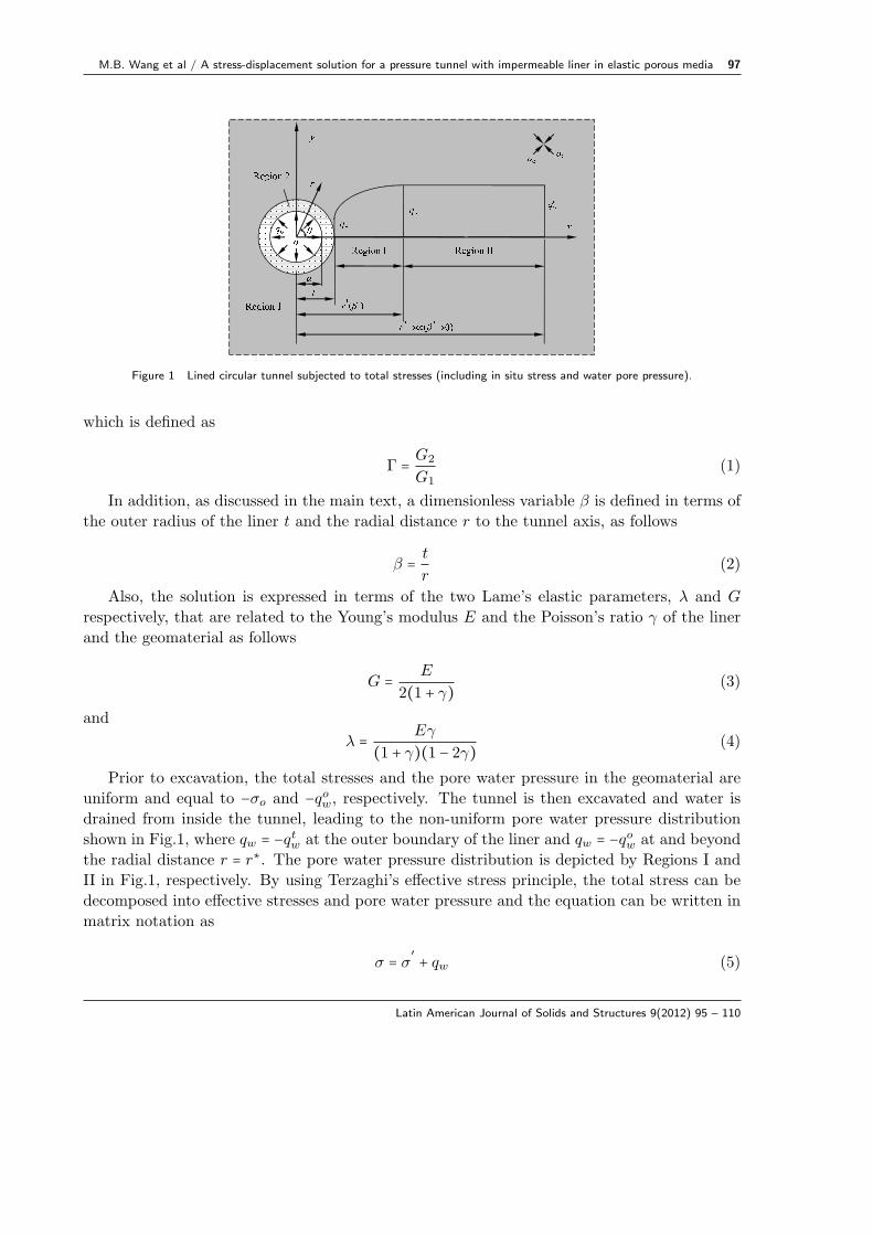
Figure 1 Lined circular tunnel subjected to total stresses (including in situ stress and water pore pressure).
which is defined as
Γ = G2
G1(1)
In addition, as discussed in the main text, a dimensionless variable β is defined in terms of
the outer radius of the liner t and the radial distance r to the tunnel axis, as follows
β = t
r(2)
Also, the solution is expressed in terms of the two Lame’s elastic parameters, λ and G
respectively, that are related to the Young’s modulus E and the Poisson’s ratio γ of the liner
and the geomaterial as follows
G = E
2(1 + γ)(3)
and
λ = Eγ
(1 + γ)(1 − 2γ)(4)
Prior to excavation, the total stresses and the pore water pressure in the geomaterial are
uniform and equal to −σo and −qow, respectively. The tunnel is then excavated and water is
drained from inside the tunnel, leading to the non-uniform pore water pressure distribution
shown in Fig.1, where qw = −qtw at the outer boundary of the liner and qw = −qow at and beyond
the radial distance r = r∗. The pore water pressure distribution is depicted by Regions I and
II in Fig.1, respectively. By using Terzaghi’s effective stress principle, the total stress can be
decomposed into effective stresses and pore water pressure and the equation can be written in
matrix notation as
σ = σ′+ qw (5)
Latin American Journal of Solids and Structures 9(2012) 95 – 110
98 M.B. Wang et al / A stress-displacement solution for a pressure tunnel with impermeable liner in elastic porous media
where σ represents a component of total normal stress, σ′the corresponding component of
effective normal stress, and qw the pore water pressure.
3 THE CLOSED-FORM FULL FIELD ELASTIC SOLUTION
According to Eq.(2), the radial distance r can therefore be expressed as follows
r = t
β(6)
In view of the relationship (6), the first derivation of an arbitrary function with respect to
the variable r, can be equally expresssed in terms of the derivative of the same function with
respect to the variable β, i.e.,
d( )dr= −β
2
t
d( )dβ
(7)
similarly, the second derivative of an arbitrary function with respect to the variable r results
d2( )dr2
= 2β3
t2d( )dβ+ β4
t2d2( )dβ2
(8)
Firstly, the solution for pore water pressure is discussed. The differential equation in a
steady flow field can be expressed in terms of the pore water pressure qw and the radial
distance r as follows [10]
d2qwdr2
+ 1
r
dqwdr= 0 (9)
In view of the transformation (6), Eq.(9) can be equally expressed in terms of β as follows
d2qwdβ2
+ 1
β
dqwdβ= 0 (10)
The general solution of Eq.(10) is obtained as follows
qw(β) = A1 +A2 lnβ (11)
where A1 and A2 are integration constants.
In reference to Fig.1, the values of the pore water pressure at the distances r = t (or β = 1)and r = r∗ are as follows, respectively
qw = −qtw β = 1 (12)
and
qw = −qow β = β∗ (13)
By substituting Eqs.(12) and (13) into Eq.(11), the coefficients A1 and A2 in Eq.(11) are
determined as
Latin American Journal of Solids and Structures 9(2012) 95 – 110
M.B. Wang et al / A stress-displacement solution for a pressure tunnel with impermeable liner in elastic porous media 99
A1 = −qtw (14)
and
A2 =qtw − qowlnβ∗
(15)
Consequently, the solutions for the pore water pressure in Regions I and II result in as
follows, respectively
qIw(β) = −qtw + (qtw − qow)lnβ
lnβ∗β∗ ≤ β ≤ 1 (16)
and
qIIw (β) = −qow 0 ≤ β ≤ β∗ (17)
Next, we discuss the derivation of the solution for displacements and stresses. Considering
Eqs.(6) and (7), the differential equation of equilibrium for the axisymmetric problem can be
expressed as
dσr
dβ− σr − σθ
β= 0 (18)
In addition, the radial strain ϵr and ϵθ can be equally expressed in terms of the radial
displacement ur and the variable β as follows, respectively
εr = −β2
t
dur
dβ(19)
and
εθ =β
aur (20)
According to Terzaghi’s effective stress principle, only the effective components of normal
stresses induce mechanical deformation, therefore, the elastic stress-strain relationships, as
defined by the theory of elasticity, may be revised as
ε1r =1
E{(σr − qw) − γ[(σθ − qw) + (σz − qw)]} (21)
ε1θ =1
E{(σθ − qw) − γ[(σr − qw) + (σz − qw)]} (22)
ε1z =1
E{(σz − qw) − γ[(σθ − qw) + (σr − qw)]} (23)
where, ε1r, ε1θ and ε1z denote the total strains including the components prior to excavation.
Similarly, prior to excavation, between the strains, defined by εor, εoθ and εoz, and the stresses
by σor , σ
oθ and σo
z , the following relationships yield
εor =1
E{(σo
r + qow) − γ [(σoθ + qow) + (σo
z + qow)]} (24)
Latin American Journal of Solids and Structures 9(2012) 95 – 110
100 M.B. Wang et al / A stress-displacement solution for a pressure tunnel with impermeable liner in elastic porous media
εoθ =1
E{(σo
θ + qow) − γ [(σor + qow) + (σo
z + qow)]} (25)
εoz =1
E{(σo
z + qow) − γ [(σoθ + qow) + (σo
r + qow)]} (26)
Hence, the incremental strains εr, εθ and εz may be obtained as follows
εr= ε1r − εor
= 1
E{(σr − qw) − (σo
r + qow) − γ[(σθ − qw) − (σoθ + qow) + (σz − qw) − (σo
z + qow)]}(27)
εθ= ε1θ − εoθ
= 1
E{(σθ − qw) − (σo
θ + qow) − γ[(σr − qw) − (σor + qow) + (σz − qw) − (σo
z + qow)]}(28)
εz= ε1z − εoz
= 1
E{(σz − qw) − (σo
z + qow) − γ[(σθ − qw) − (σoθ + qow) + (σr − qw) − (σo
r + qow)]}(29)
In terms of Eqs.(27)-(29), for the special case of plane strain, i.e., εz = 0, the following
expressions results in
(σr − qw) + (σo − qow) = (λ + 2G)εr + λεθ (30)
(σθ − qw) + (σo − qow) = (λ + 2G)εθ + λεr (31)
(σz − qw) + (σo − qow) = λ(εr + εθ) (32)
wherein, σr − qw, σθ − qw and σz − qw represent the effective components of radial, tangential
and axial stresses, respectively, while σo − qow represent the initial effective in situ stress.
By substituting Eqs.(30) and (31) together with Eqs.(19) and (20) into Eq.(18), the follow-
ing differential equation representing the equilibrium condition in terms of the displacements
is obtained
β2d2ur1
dβ2+ βdur1
dβ− ur1 −
t
λ1 + 2G1
dqwdβ= 0 (33)
where, the second subscripts 1 is related to the components in the surrounding geomaterial.
For region I, noting Eq.(16), the solution of Eq.(33) gives the following expression for the radial
displacement
uIr1 (β) =
AI1
β+AI
2β +t (qow − qtw)2 (λ1 + 2G1)
lnβ
β lnβ∗(34)
where, the superscript I is related to the components in the region I of the surrounding geoma-
terial. In addition, based on Eqs.(30) and (31), the radial and tangential stresses are obtained
as, respectively
Latin American Journal of Solids and Structures 9(2012) 95 – 110
M.B. Wang et al / A stress-displacement solution for a pressure tunnel with impermeable liner in elastic porous media 101
σIr1 (β) = −σo + (qow − qtw) +
2 (λ1 +G1)t
AI1 −
2G1
tβ2AI
2 −qow − qtw2 lnβ∗
(1 + 2G1
λ1 + 2G1lnβ) (35)
andσIθ1 (β) = −σo + (qow − qtw) +
2(λ1+G1)t
AI1 + 2G1
tβ2AI
2
−qow−qtw
2 lnβ∗( λ1
λ1+2G1+ 2G1
λ1+2G1lnβ)
(36)
As for region II, noting Eq.(17), the following expressions for the displacement and stresses
result in
uIIr1 (β) =
AII1
β+AII
2 β (37)
σIIr1 (β) = −σo + (qow − qtw) +
2 (λ1 +G1)t
AII1 −
2G1
tβ2AII
2 (38)
σBθ1 (β) = −σo + (qow − qtw) +
2 (λ1 +G1)t
AII1 +
2G1
tβ2AII
2 (39)
where, the superscript II is related to the components in the region II of the surrounding
geomaterial.
In reference to Fig.1, the boundary or continuity conditions at the distances r = t (or β = 1),r →∞ (or β → 0) and r = r∗ (or β = β∗) are summarized as
σIr1 = − (qs + qtw) β = 1 (40)
σIIr1 = −σo β = 0 (41)
σIr1 = σII
r1 β = β∗ (42)
uIr1 = uII
r1 β = β∗ (43)
where, qs denotes the normal pressure along the interface between the liner and the surrounding
geomaterial for the case that the liner is impermeable. Eqs.(40) through (43) – with σIr1, σ
IIr1 ,
uIr1 and uII
r1 defined by Eqs.(35), (38), (34) and (37), respectively – conform a system of four
algebraic equations to solve four unknowns, the variables AI1, A
I2, A
II1 and AII
2 , as follows
AI1 =
t
2 (λ1 + 2G1)(qtw − qow)(1 −
1
2 lnβ∗) (44)
AI2 =
t
2G1
(qs + qtw − σo) +t
2 (λ1 + 2G1)(qtw − qow) (
1
2 lnβ∗− 1) (45)
AII1 = 0 (46)
AII2 =
t
2G1
(qs + qtw − σo) +t
2 (λ1 + 2G1)(qtw − qow) [
1
2 lnβ∗− 1 − 1
2 (β∗)2 lnβ∗] (47)
Latin American Journal of Solids and Structures 9(2012) 95 – 110
102 M.B. Wang et al / A stress-displacement solution for a pressure tunnel with impermeable liner in elastic porous media
In summary, substituting Eqs.(44) and (45) into Eqs.(34)-(36) and Eqs.(46) and (47) into
Eqs.(37)-(39), respectively, the final expressions for the displacements and stresses for regions
I and II are obtained as follows
uIr1 (β) =
t
2G1
(qs + qtw − σo)β −t
4 (λ1 + 2G1)qtw − qowβ lnβ∗
[2 lnβ + (1 − β2) (1 − 2 lnβ∗)] (48)
σIr1 (β) = −σo − (qs + qtw − σo)β2 + 2G1
4 (λ1 + 2G1)qtw − qowlnβ∗
[2 lnβ + (1 − β2) (1 − 2 lnβ∗)] (49)
σIθ1 (β) = −σo + (qs + qtw − σo)β2 + 2G1
4 (λ1 + 2G1)qtw − qowlnβ∗
[2 lnβ − 2 + (1 + β2) (1 − 2 lnβ∗)] (50)
uIIr1 (β) =
t
2G1
(qs + qtw − σo)β −t
4 (λ1 + 2G1)qtw − qow(β∗)2 lnβ∗
β [1 − (β∗)2 + 2 (β∗)2 lnβ∗] (51)
σIIr1 (β) = −σo − (qs + qtw − σo)β2 + 2G1
4 (λ1 + 2G1)qtw − qow(β∗)2 lnβ∗
β2 [1 − (β∗)2 + 2 (β∗)2 lnβ∗] (52)
σIIθ1 (β) = −σo + (qs + qtw − σo)β2 − 2G1
4 (λ1 + 2G1)qtw − qow(β∗)2 lnβ∗
β2 [1 − (β∗)2 + 2 (β∗)2 lnβ∗] (53)
The above expressions for radial and tangential stresses correspond to total stresses. Ac-
cording to Terzaghi’s effective stress principle (Eq.(5)), the effective radial and tangential
stresses for regions I and II, are computed as follows
σ′r(β) = σr(β) − qw(β) (54)
σ′θ(β) = σθ(β) − qw(β) (55)
By making qtw = qow = 0 in Eqs.(48)-(53), the classical Lame’s solution can be recovered. In
this case, the total and effective stresses are the same and the solution for radial displacement,
radial stress and tangential stress, result to be, respectively
ur1 (β) =t
2G1(qs − σo)β (56)
σr1 (β) = −σo − (qs − σo)β2 (57)
σθ1 (β) = −σo + (qs − σo)β2 (58)
For another special case that the pore water pressure distribution in the surrounding ge-
omaterial is uniform, by considering qtw = qow in Eqs.(48)-(53), the following expressions for
displacement and stresses are obtained
ur1 (β) =t
2G1(qs + qow − σo)β (59)
Latin American Journal of Solids and Structures 9(2012) 95 – 110
M.B. Wang et al / A stress-displacement solution for a pressure tunnel with impermeable liner in elastic porous media 103
σr1 (β) = −σo − (qs + qow − σo)β2 (60)
σθ1 (β) = −σo + (qs + qow − σo)β2 (61)
For this case there is no distinction between regions I and II, in terms of Eqs.(16) and (17),
the solution for the pore water pressure is
qw(β) = qIw(β) = qIIw (β) = −qow (62)
Figure 2 Model for tunnel construction.
Finally, the solution for the support pressure qs is discussed below. It is assumed that the
radii of the opening immediately after excavation, after the elastic deformation finishes and
before the liner is installed, are t′′′, t
′′and t
′, respectively. The construction sequence of the
tunnel is modeled with regard to Fig.2. Then, we define
η = t′− t
′′
t′(63)
as the relative radius misfit between the surrounding geomaterial and the liner. This misfit is
assumed of the order of the admissible strains in linear elasticity.
Based on Kirsch’s solution [11] and Eq.(48), t′′is expressed as follows
t′′= t
′′′[1 − σo
2G1] (64)
The case of η = 0 means that the liner is installed after the elastic deformation finishes,
and η = ηmax means that the region of r ≤ t′′′
in the surrounding geomaterial is replaced by
the liner. Thus, ηmax can be written in the following form
ηmax =t′′′− t
′′
t′′′= σo
2G1(65)
Substituting (65) into (64) yields the following relation
t′′= (1 − ηmax) t
′′′(66)
Latin American Journal of Solids and Structures 9(2012) 95 – 110
104 M.B. Wang et al / A stress-displacement solution for a pressure tunnel with impermeable liner in elastic porous media
Next, the elastic deformation rate of the surrounding geomaterial is defined by
δ = t′′′− t
′
t′′′ − t′′× 100% (67)
Taking advantage of Eq.(66), δ can be rewritten
δ = 1
ηmax(1 − t
′
t′′′) × 100% (68)
Inserting Eqs.(65), (66) and (68) into Eq.(63) gives
η = (1 − δ)ηmax
1 − δηmax(69)
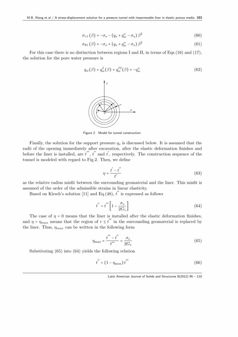
Figure 3 Mechanical model for the liner.
In terms of the Lame’s solution and Eq.(6), the stresses and displacement in the liner may
be equally written as follows (see Fig.3)
σ′
r2 (β) = σr2 (β) = −β2 − 1t2
a2 − 1qo −
1 − a2
t2β2
1 − a2
t2
qs (70)
σ′
θ2 (β) = σθ2 (β) =β2 + 1t2
a2 − 1qo −
1 + a2
t2β2
1 − a2
t2
qs (71)
ur2 (β) =1
2G2
β
t
⎡⎢⎢⎢⎢⎣
(1 − 2γ2) a2
β2 + a2
1 − a2
t2
qo −(1 − 2γ2) t2
β2 + a2
1 − a2
t2
qs
⎤⎥⎥⎥⎥⎦(72)
Furthermore, it is noted that the liner will be installed when the tunnel partially deforms.
Hence, the following relationship results in
uIr1 (1)∣σo=0
= ur2 (1) + ηt (73)
By substituting Eqs.(48) and (72) into Eq.(73), the expression of qs is obtained
Latin American Journal of Solids and Structures 9(2012) 95 – 110

M.B. Wang et al / A stress-displacement solution for a pressure tunnel with impermeable liner in elastic porous media 105
qs =2 (1 − γ2)a2qo + (2ηG2 − Γqtw) (t2 − a2)
(1 − 2γ2 + Γ) t2 + (1 − Γ)a2(74)
In terms of Eq.(48), the displacement along the interface between the liner and the sur-
rounding geomaterial may also be written in a explicit form as follows
uIr1 (1) =
ηtΓ(t2−a2)(1−2γ2+Γ)t2+(1−Γ)a2 + t
2G1
(1−2γ2)a2+a2
(1−2γ2+Γ)t2+(1−Γ)a2 qo
+ t2G1
(1−2γ2)t2+a2
(1−2γ2+Γ)t2+(1−Γ)a2 qtw − t
2G1σo
(75)
where and hereafter, uIr1(1) denotes the support displacement corresponding to the case that
the liner is impermeable.
In terms of Eqs.(74) and (75), it may be found that the pore water pressure distribution in
the surrounding geomaterial has significant influences on the support pressure qs and displace-
ment uIr1(1). The support pressure qs and displacement uI
r1(1) may decrease with increasing
the pore water pressure qtw along the outer boundary of the liner and the reverse trend may
occur if to decrease the pore water pressure qtw. As for the internal water pressure qo, it may
be found that the support pressure qs increases with increasing the internal water pressure
qo. However, the support displacement uIr1(1) decreases with increasing the internal water
pressure qo.
4 NUMERICAL RESULTS AND DISCUSSIONS
In this Section, in order to illustrate the appllication of the obtained solution, we take γ1 =γ2 = 0.3, δ = 0, G1/σo = 103, qow = 0.5σo, q
tw = 0.025σo, qo = 0.05σo and r∗ = 5a2/t.
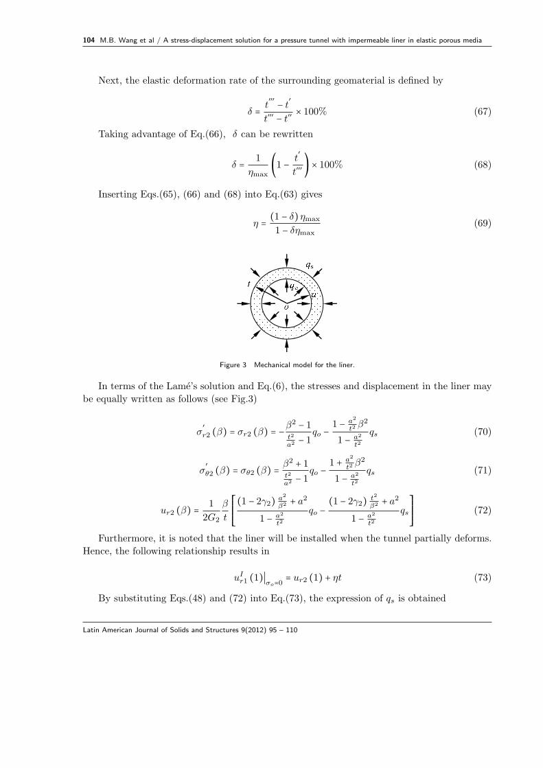
The variations of the normalized support pressure (qs/σo) and displacement (G1uIr1(1)/(σoa))
with relative liner rigidity for various relative liner thicknesses are depicted in Figs.4 and 5. It
is seen that in general the varying trend of the support pressure with respect to relative liner
rigidity for various liner thicknesses is similar to that of the support displacement. Namely,
both of the support pressure and displacement monotonically increase with increasing liner
rigidity and thickness. From Figs.4 and 5, it is further seen that in the range of 1 ≤ Γ ≤ 200,the influences of the liner rigidity and thickness on the support pressure and displacement are
significant. However, in the range of 200 < Γ ≤ 800, the variations of the support pressure and
displacement with various values of Γ or t/a become insignificant. Finally, when 800 < Γ, thevariations of the support pressure and displacement are almost independent of the values of Γ
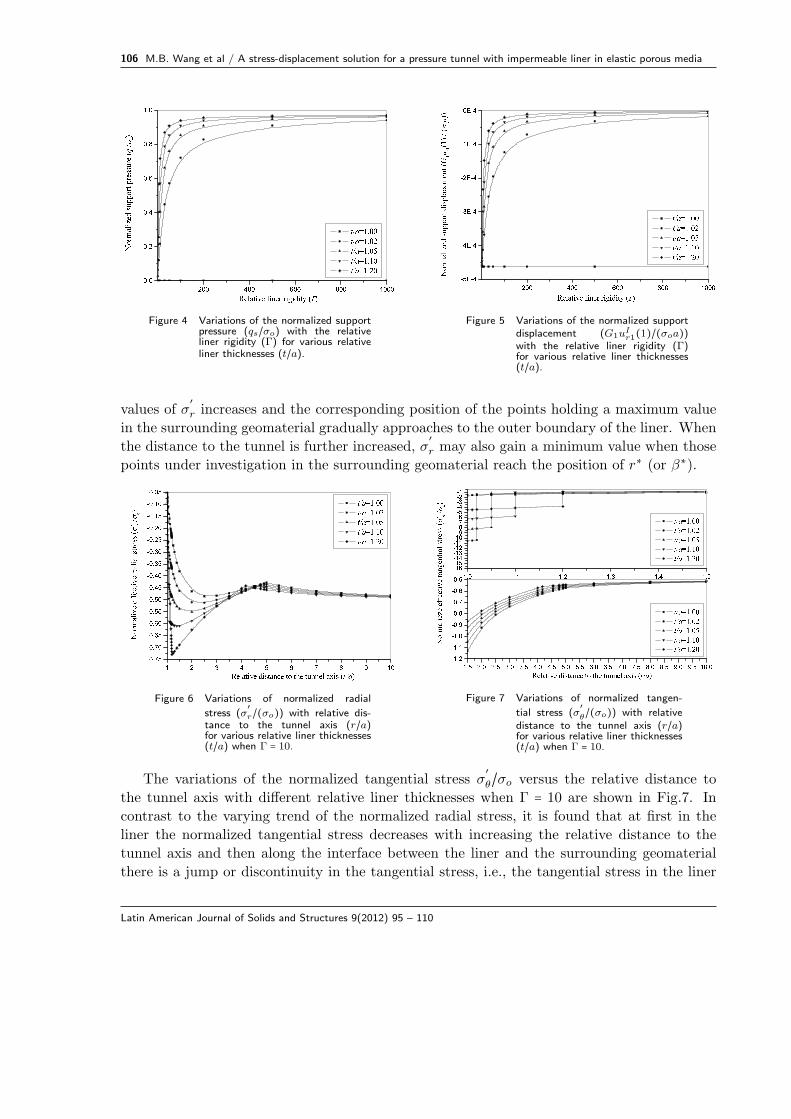
and t/a.In Figs.6 and 7, we illustrate the variations of the normalized effective stresses in the liner
and the surrounding geomaterial with relative liner thickness (t/a) and distance to the tunnel
axis (r/a) when Γ = 10 [9, 15]. It is found from Fig.6 that at first the effective radial stress
increases with increasing distance to the tunnel axis and then holds a maximum value when the
distance to the tunnel axis reaches a certain magnitude for a specific liner thickness. Moreover,
it is observed that with increasing relative liner thickness these aforementioned maximum
Latin American Journal of Solids and Structures 9(2012) 95 – 110
106 M.B. Wang et al / A stress-displacement solution for a pressure tunnel with impermeable liner in elastic porous media
Figure 4 Variations of the normalized supportpressure (qs/σo) with the relativeliner rigidity (Γ) for various relativeliner thicknesses (t/a).
Figure 5 Variations of the normalized supportdisplacement (G1u
Ir1(1)/(σoa))
with the relative liner rigidity (Γ)for various relative liner thicknesses(t/a).
values of σ′
r increases and the corresponding position of the points holding a maximum value
in the surrounding geomaterial gradually approaches to the outer boundary of the liner. When
the distance to the tunnel is further increased, σ′
r may also gain a minimum value when those
points under investigation in the surrounding geomaterial reach the position of r∗ (or β∗).
Figure 6 Variations of normalized radial
stress (σ′r/(σo)) with relative dis-
tance to the tunnel axis (r/a)for various relative liner thicknesses(t/a) when Γ = 10.
Figure 7 Variations of normalized tangen-
tial stress (σ′θ/(σo)) with relative
distance to the tunnel axis (r/a)for various relative liner thicknesses(t/a) when Γ = 10.
The variations of the normalized tangential stress σ′
θ/σo versus the relative distance to
the tunnel axis with different relative liner thicknesses when Γ = 10 are shown in Fig.7. In
contrast to the varying trend of the normalized radial stress, it is found that at first in the
liner the normalized tangential stress decreases with increasing the relative distance to the
tunnel axis and then along the interface between the liner and the surrounding geomaterial
there is a jump or discontinuity in the tangential stress, i.e., the tangential stress in the liner
Latin American Journal of Solids and Structures 9(2012) 95 – 110
M.B. Wang et al / A stress-displacement solution for a pressure tunnel with impermeable liner in elastic porous media 107
is much higher than that in the surrounding geomaterial. And the jump values decrease with
increasing relative liner thickness. As for the tangential stress in the surrounding geomaterial,
it is found that σ′
θ/σo also decreases with increasing r/a and t/a. In addition, compared with
the variation of the radial stress at r = r∗, it may be observed that the tangential stress does
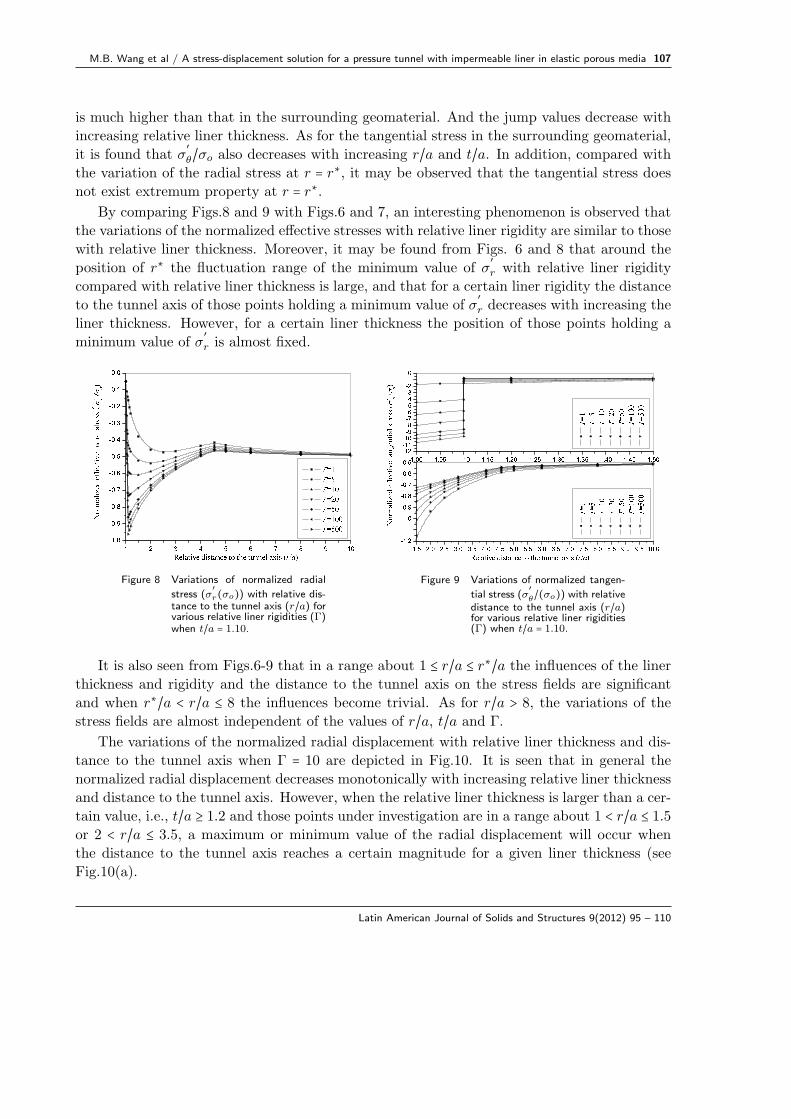
not exist extremum property at r = r∗.By comparing Figs.8 and 9 with Figs.6 and 7, an interesting phenomenon is observed that
the variations of the normalized effective stresses with relative liner rigidity are similar to those
with relative liner thickness. Moreover, it may be found from Figs. 6 and 8 that around the
position of r∗ the fluctuation range of the minimum value of σ′
r with relative liner rigidity
compared with relative liner thickness is large, and that for a certain liner rigidity the distance
to the tunnel axis of those points holding a minimum value of σ′
r decreases with increasing the
liner thickness. However, for a certain liner thickness the position of those points holding a
minimum value of σ′
r is almost fixed.
Figure 8 Variations of normalized radial
stress (σ′r(σo)) with relative dis-
tance to the tunnel axis (r/a) forvarious relative liner rigidities (Γ)when t/a = 1.10.
Figure 9 Variations of normalized tangen-
tial stress (σ′θ/(σo)) with relative
distance to the tunnel axis (r/a)for various relative liner rigidities(Γ) when t/a = 1.10.
It is also seen from Figs.6-9 that in a range about 1 ≤ r/a ≤ r∗/a the influences of the liner
thickness and rigidity and the distance to the tunnel axis on the stress fields are significant
and when r∗/a < r/a ≤ 8 the influences become trivial. As for r/a > 8, the variations of the
stress fields are almost independent of the values of r/a, t/a and Γ.
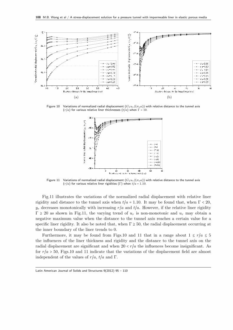
The variations of the normalized radial displacement with relative liner thickness and dis-
tance to the tunnel axis when Γ = 10 are depicted in Fig.10. It is seen that in general the
normalized radial displacement decreases monotonically with increasing relative liner thickness
and distance to the tunnel axis. However, when the relative liner thickness is larger than a cer-
tain value, i.e., t/a ≥ 1.2 and those points under investigation are in a range about 1 < r/a ≤ 1.5or 2 < r/a ≤ 3.5, a maximum or minimum value of the radial displacement will occur when
the distance to the tunnel axis reaches a certain magnitude for a given liner thickness (see
Fig.10(a).
Latin American Journal of Solids and Structures 9(2012) 95 – 110
108 M.B. Wang et al / A stress-displacement solution for a pressure tunnel with impermeable liner in elastic porous media
(a) (b)
Figure 10 Variations of normalized radial displacement (G1ur/(σoa)) with relative distance to the tunnel axis(r/a) for various relative liner thicknesses (t/a) when Γ = 10.
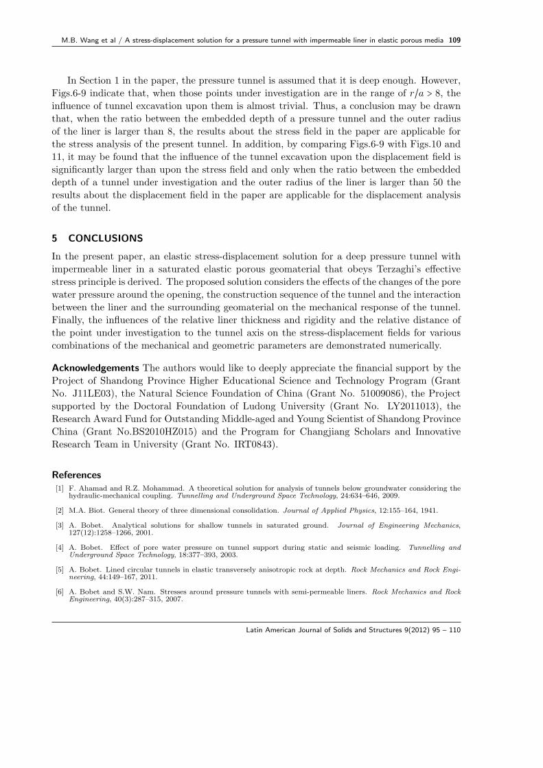
Figure 11 Variations of normalized radial displacement (G1ur/(σoa)) with relative distance to the tunnel axis(r/a) for various relative liner rigidities (Γ) when t/a = 1.10.
Fig.11 illustrates the variations of the normalized radial displacement with relative liner
rigidity and distance to the tunnel axis when t/a = 1.10. It may be found that, when Γ < 20,yr decreases monotonically with increasing r/a and t/a. However, if the relative liner rigidity
Γ ≥ 20 as shown in Fig.11, the varying trend of ur is non-monotonic and ur may obtain a
negative maximum value when the distance to the tunnel axis reaches a certain value for a
specific liner rigidity. It also be noted that, when Γ ≥ 50, the radial displacement occurring at
the inner boundary of the liner trends to 0.
Furthermore, it may be found from Figs.10 and 11 that in a range about 1 ≤ r/a ≤ 5
the influences of the liner thickness and rigidity and the distance to the tunnel axis on the
radial displacement are significant and when 20 < r/a the influences become insignificant. As
for r/a > 50, Figs.10 and 11 indicate that the variations of the displacement field are almost
independent of the values of r/a, t/a and Γ.
Latin American Journal of Solids and Structures 9(2012) 95 – 110
M.B. Wang et al / A stress-displacement solution for a pressure tunnel with impermeable liner in elastic porous media 109
In Section 1 in the paper, the pressure tunnel is assumed that it is deep enough. However,
Figs.6-9 indicate that, when those points under investigation are in the range of r/a > 8, theinfluence of tunnel excavation upon them is almost trivial. Thus, a conclusion may be drawn
that, when the ratio between the embedded depth of a pressure tunnel and the outer radius
of the liner is larger than 8, the results about the stress field in the paper are applicable for
the stress analysis of the present tunnel. In addition, by comparing Figs.6-9 with Figs.10 and
11, it may be found that the influence of the tunnel excavation upon the displacement field is
significantly larger than upon the stress field and only when the ratio between the embedded
depth of a tunnel under investigation and the outer radius of the liner is larger than 50 the
results about the displacement field in the paper are applicable for the displacement analysis
of the tunnel.
5 CONCLUSIONS
In the present paper, an elastic stress-displacement solution for a deep pressure tunnel with
impermeable liner in a saturated elastic porous geomaterial that obeys Terzaghi’s effective
stress principle is derived. The proposed solution considers the effects of the changes of the pore
water pressure around the opening, the construction sequence of the tunnel and the interaction
between the liner and the surrounding geomaterial on the mechanical response of the tunnel.
Finally, the influences of the relative liner thickness and rigidity and the relative distance of
the point under investigation to the tunnel axis on the stress-displacement fields for various
combinations of the mechanical and geometric parameters are demonstrated numerically.
Acknowledgements The authors would like to deeply appreciate the financial support by the
Project of Shandong Province Higher Educational Science and Technology Program (Grant
No. J11LE03), the Natural Science Foundation of China (Grant No. 51009086), the Project
supported by the Doctoral Foundation of Ludong University (Grant No. LY2011013), the
Research Award Fund for Outstanding Middle-aged and Young Scientist of Shandong Province
China (Grant No.BS2010HZ015) and the Program for Changjiang Scholars and Innovative
Research Team in University (Grant No. IRT0843).
References[1] F. Ahamad and R.Z. Mohammad. A theoretical solution for analysis of tunnels below groundwater considering the
hydraulic-mechanical coupling. Tunnelling and Underground Space Technology, 24:634–646, 2009.
[2] M.A. Biot. General theory of three dimensional consolidation. Journal of Applied Physics, 12:155–164, 1941.
[3] A. Bobet. Analytical solutions for shallow tunnels in saturated ground. Journal of Engineering Mechanics,127(12):1258–1266, 2001.
[4] A. Bobet. Effect of pore water pressure on tunnel support during static and seismic loading. Tunnelling andUnderground Space Technology, 18:377–393, 2003.
[5] A. Bobet. Lined circular tunnels in elastic transversely anisotropic rock at depth. Rock Mechanics and Rock Engi-neering, 44:149–167, 2011.
[6] A. Bobet and S.W. Nam. Stresses around pressure tunnels with semi-permeable liners. Rock Mechanics and RockEngineering, 40(3):287–315, 2007.
Latin American Journal of Solids and Structures 9(2012) 95 – 110
110 M.B. Wang et al / A stress-displacement solution for a pressure tunnel with impermeable liner in elastic porous media
[7] B.H.G. Brady and E.T. Brown. Rock mechanics for underground mining. Allen & Unwin, 1985.
[8] W.I. Chou and A. Bobet. Predictions of ground deformations in shallow tunnels in clay. Tunnelling and UndergroundSpace Technology, 17:3–19, 2002.
[9] H.H. Einstein and C.W. Schwartz. Simplified analysis for tunnel supports. Journal of Geotechnical EngineeringDivision, GT4:499–518, 1979.
[10] J.C. Jaeger, N.G.W. Cook, and R. Zimmerman. Fundamentals of rock mechanics. Blackwell Publishing, Oxford,2007.
[11] G. Kirsch. Die theorie der elastizitat und die bedurfnisse der festigkeitslehre. Zeitschrift des Vereines DeutscherIn.genieure, 42:797–807, 1898.
[12] S.W. Lee, J.W. Jung, S.W. Nam, and I.M. Lee. The influence of seepage forces on ground reaction curve of circularopening. Tunnelling and Underground Space Technology, 22:28–38, 2006.
[13] S.W. Nam and A. Bobet. Liner stresses in deep tunnels below the water table. Tunnelling Underground SpaceTechnology, 21:626–635, 2006.
[14] F. Pellet, F. Descoeudres, and P. Egger. The effect of water seepage forces on the face stability of an experimentalmicrotunnel. Canadian Geotechnical Journal, 30:363–369, 1993.
[15] H.G. Poulos and E.H. Davis. Elastic solutions for soil and rock mechanics. Wiley, New York, 1974.
[16] Y.J. Shin, B.M. Kim, J.H. Shin, and I.M. Lee. The ground reaction curve of underwater tunnels considering seepageforces. Tunnelling and Underground Space Technology, 25:315–324, 2010.
[17] Y.J. Shin, K.I. Song, I.M. Lee, and G.C. Cho. Interaction between tunnel supports and ground convergence –consideration of seepage forces. International Journal of Rock Mechanics & Mining Sciences, 48:394–405, 2011.
[18] K. Terzaghi. Theoretical soil mechanics. Wiley, New York, 1943.
Latin American Journal of Solids and Structures 9(2012) 95 – 110