Embed Size (px)
Citation preview
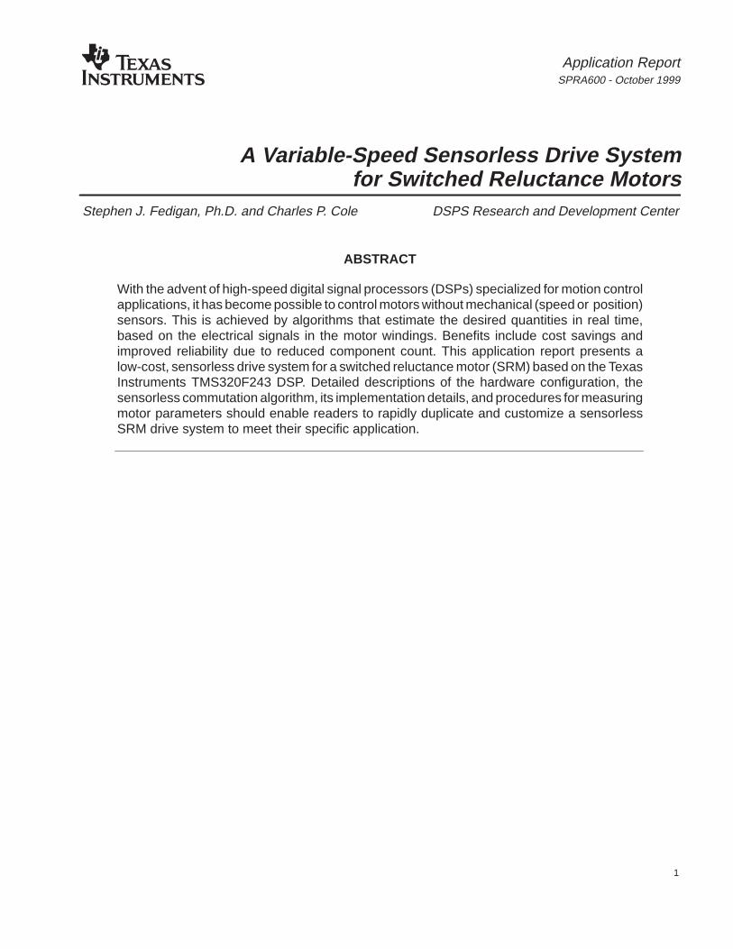
Application ReportSPRA600 - October 1999
1
A Variable-Speed Sensorless Drive Systemfor Switched Reluctance Motors
Stephen J. Fedigan, Ph.D. and Charles P. Cole DSPS Research and Development Center
ABSTRACT
With the advent of high-speed digital signal processors (DSPs) specialized for motion controlapplications, it has become possible to control motors without mechanical (speed or position)sensors. This is achieved by algorithms that estimate the desired quantities in real time,based on the electrical signals in the motor windings. Benefits include cost savings andimproved reliability due to reduced component count. This application report presents alow-cost, sensorless drive system for a switched reluctance motor (SRM) based on the TexasInstruments TMS320F243 DSP. Detailed descriptions of the hardware configuration, thesensorless commutation algorithm, its implementation details, and procedures for measuringmotor parameters should enable readers to rapidly duplicate and customize a sensorlessSRM drive system to meet their specific application.
SPRA600
2 A Variable-Speed Sensorless Drive System for Switched Reluctance Motors
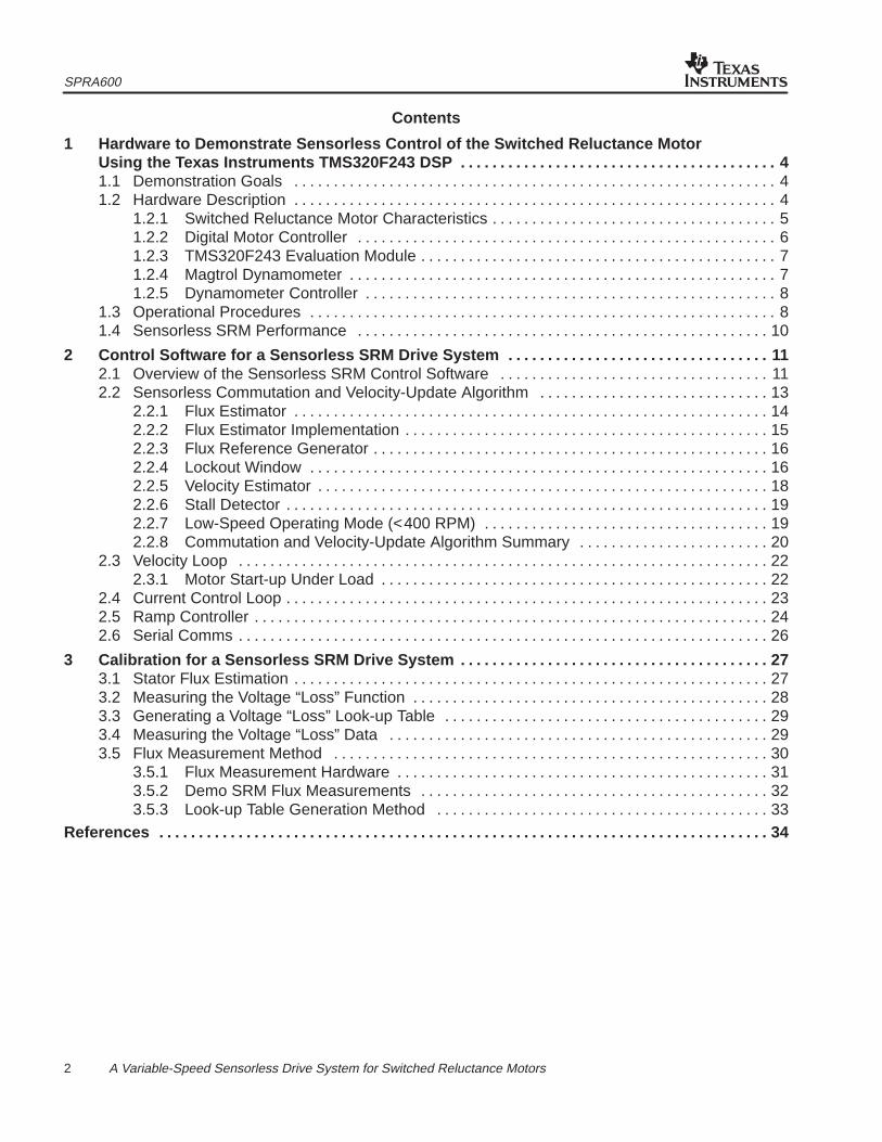
Contents
1 Hardware to Demonstrate Sensorless Control of the Switched Reluctance MotorUsing the Texas Instruments TMS320F243 DSP 4. . . . . . . . . . . . . . . . . . . . . . . . . . . . . . . . . . . . . . . . 1.1 Demonstration Goals 4. . . . . . . . . . . . . . . . . . . . . . . . . . . . . . . . . . . . . . . . . . . . . . . . . . . . . . . . . . . . . 1.2 Hardware Description 4. . . . . . . . . . . . . . . . . . . . . . . . . . . . . . . . . . . . . . . . . . . . . . . . . . . . . . . . . . . . .
1.2.1 Switched Reluctance Motor Characteristics 5. . . . . . . . . . . . . . . . . . . . . . . . . . . . . . . . . . . . 1.2.2 Digital Motor Controller 6. . . . . . . . . . . . . . . . . . . . . . . . . . . . . . . . . . . . . . . . . . . . . . . . . . . . . 1.2.3 TMS320F243 Evaluation Module 7. . . . . . . . . . . . . . . . . . . . . . . . . . . . . . . . . . . . . . . . . . . . . 1.2.4 Magtrol Dynamometer 7. . . . . . . . . . . . . . . . . . . . . . . . . . . . . . . . . . . . . . . . . . . . . . . . . . . . . . 1.2.5 Dynamometer Controller 8. . . . . . . . . . . . . . . . . . . . . . . . . . . . . . . . . . . . . . . . . . . . . . . . . . . .
1.3 Operational Procedures 8. . . . . . . . . . . . . . . . . . . . . . . . . . . . . . . . . . . . . . . . . . . . . . . . . . . . . . . . . . . 1.4 Sensorless SRM Performance 10. . . . . . . . . . . . . . . . . . . . . . . . . . . . . . . . . . . . . . . . . . . . . . . . . . . .
2 Control Software for a Sensorless SRM Drive System 11. . . . . . . . . . . . . . . . . . . . . . . . . . . . . . . . . 2.1 Overview of the Sensorless SRM Control Software 11. . . . . . . . . . . . . . . . . . . . . . . . . . . . . . . . . . 2.2 Sensorless Commutation and Velocity-Update Algorithm 13. . . . . . . . . . . . . . . . . . . . . . . . . . . . .
2.2.1 Flux Estimator 14. . . . . . . . . . . . . . . . . . . . . . . . . . . . . . . . . . . . . . . . . . . . . . . . . . . . . . . . . . . . 2.2.2 Flux Estimator Implementation 15. . . . . . . . . . . . . . . . . . . . . . . . . . . . . . . . . . . . . . . . . . . . . . 2.2.3 Flux Reference Generator 16. . . . . . . . . . . . . . . . . . . . . . . . . . . . . . . . . . . . . . . . . . . . . . . . . . 2.2.4 Lockout Window 16. . . . . . . . . . . . . . . . . . . . . . . . . . . . . . . . . . . . . . . . . . . . . . . . . . . . . . . . . . 2.2.5 Velocity Estimator 18. . . . . . . . . . . . . . . . . . . . . . . . . . . . . . . . . . . . . . . . . . . . . . . . . . . . . . . . . 2.2.6 Stall Detector 19. . . . . . . . . . . . . . . . . . . . . . . . . . . . . . . . . . . . . . . . . . . . . . . . . . . . . . . . . . . . . 2.2.7 Low-Speed Operating Mode (<400 RPM) 19. . . . . . . . . . . . . . . . . . . . . . . . . . . . . . . . . . . . 2.2.8 Commutation and Velocity-Update Algorithm Summary 20. . . . . . . . . . . . . . . . . . . . . . . .
2.3 Velocity Loop 22. . . . . . . . . . . . . . . . . . . . . . . . . . . . . . . . . . . . . . . . . . . . . . . . . . . . . . . . . . . . . . . . . . . 2.3.1 Motor Start-up Under Load 22. . . . . . . . . . . . . . . . . . . . . . . . . . . . . . . . . . . . . . . . . . . . . . . . .
2.4 Current Control Loop 23. . . . . . . . . . . . . . . . . . . . . . . . . . . . . . . . . . . . . . . . . . . . . . . . . . . . . . . . . . . . . 2.5 Ramp Controller 24. . . . . . . . . . . . . . . . . . . . . . . . . . . . . . . . . . . . . . . . . . . . . . . . . . . . . . . . . . . . . . . . . 2.6 Serial Comms 26. . . . . . . . . . . . . . . . . . . . . . . . . . . . . . . . . . . . . . . . . . . . . . . . . . . . . . . . . . . . . . . . . . .
3 Calibration for a Sensorless SRM Drive System 27. . . . . . . . . . . . . . . . . . . . . . . . . . . . . . . . . . . . . . . 3.1 Stator Flux Estimation 27. . . . . . . . . . . . . . . . . . . . . . . . . . . . . . . . . . . . . . . . . . . . . . . . . . . . . . . . . . . . 3.2 Measuring the Voltage “Loss” Function 28. . . . . . . . . . . . . . . . . . . . . . . . . . . . . . . . . . . . . . . . . . . . . 3.3 Generating a Voltage “Loss” Look-up Table 29. . . . . . . . . . . . . . . . . . . . . . . . . . . . . . . . . . . . . . . . . 3.4 Measuring the Voltage “Loss” Data 29. . . . . . . . . . . . . . . . . . . . . . . . . . . . . . . . . . . . . . . . . . . . . . . . 3.5 Flux Measurement Method 30. . . . . . . . . . . . . . . . . . . . . . . . . . . . . . . . . . . . . . . . . . . . . . . . . . . . . . .
3.5.1 Flux Measurement Hardware 31. . . . . . . . . . . . . . . . . . . . . . . . . . . . . . . . . . . . . . . . . . . . . . . 3.5.2 Demo SRM Flux Measurements 32. . . . . . . . . . . . . . . . . . . . . . . . . . . . . . . . . . . . . . . . . . . . 3.5.3 Look-up Table Generation Method 33. . . . . . . . . . . . . . . . . . . . . . . . . . . . . . . . . . . . . . . . . .
References 34. . . . . . . . . . . . . . . . . . . . . . . . . . . . . . . . . . . . . . . . . . . . . . . . . . . . . . . . . . . . . . . . . . . . . . . . . . . . .
SPRA600
3 A Variable-Speed Sensorless Drive System for Switched Reluctance Motors
List of Figures
Figure 1. Interconnection Diagram for SRM Demo Hardware 5. . . . . . . . . . . . . . . . . . . . . . . . . . . . . . . . . . Figure 2. SRM Power Driver Topology 6. . . . . . . . . . . . . . . . . . . . . . . . . . . . . . . . . . . . . . . . . . . . . . . . . . . . . . Figure 3. Software Block and Timing Diagrams 12. . . . . . . . . . . . . . . . . . . . . . . . . . . . . . . . . . . . . . . . . . . . . Figure 4. Graph of Flux Estimate and Flux Threshold vs. Time 14. . . . . . . . . . . . . . . . . . . . . . . . . . . . . . . . Figure 5. SRM Power Driver Topology 15. . . . . . . . . . . . . . . . . . . . . . . . . . . . . . . . . . . . . . . . . . . . . . . . . . . . . Figure 6. Flux Estimator Code 16. . . . . . . . . . . . . . . . . . . . . . . . . . . . . . . . . . . . . . . . . . . . . . . . . . . . . . . . . . . . Figure 7. Flux Estimate and Threshold at 2500 RPM Under Full Load 17. . . . . . . . . . . . . . . . . . . . . . . . . Figure 8. Illustration of Sensorless Commutation Algorithm With Lockout Window 18. . . . . . . . . . . . . . . Figure 9. Low-Speed Operating Mode With a Second Flux Threshold
for an Additional Velocity Update 19. . . . . . . . . . . . . . . . . . . . . . . . . . . . . . . . . . . . . . . . . . . . . . . . . Figure 10. Commutation and Velocity-Update Flow Diagram 21. . . . . . . . . . . . . . . . . . . . . . . . . . . . . . . . . . . Figure 11. Block Diagram of the Velocity Control Loop 22. . . . . . . . . . . . . . . . . . . . . . . . . . . . . . . . . . . . . . . . Figure 12. Instantaneous Velocity Estimate and Velocity Loop Output During Start-up 23. . . . . . . . . . . . Figure 13. Block Diagram of the Current Control Loop 23. . . . . . . . . . . . . . . . . . . . . . . . . . . . . . . . . . . . . . . . Figure 14. State Transition Diagram for the Ramp Controller 25. . . . . . . . . . . . . . . . . . . . . . . . . . . . . . . . . . Figure 15. Flow Chart for Voltage “Loss” Measurement Program 28. . . . . . . . . . . . . . . . . . . . . . . . . . . . . . . Figure 16. Voltage “Loss” vs. Current for the Emerson Electric SRM and the
Spectrum Digital Motor Control Board 30. . . . . . . . . . . . . . . . . . . . . . . . . . . . . . . . . . . . . . . . . . . . . Figure 17. SRM Magnetization Curves 31. . . . . . . . . . . . . . . . . . . . . . . . . . . . . . . . . . . . . . . . . . . . . . . . . . . . . Figure 18. Analog Flux Measurement Circuit 32. . . . . . . . . . . . . . . . . . . . . . . . . . . . . . . . . . . . . . . . . . . . . . . . Figure 19. Flux Linkage Curves for Demo Platform SRM 33. . . . . . . . . . . . . . . . . . . . . . . . . . . . . . . . . . . . . .
List of Tables
Table 1. Performance Parameters of the Demo SRM Drive System 4. . . . . . . . . . . . . . . . . . . . . . . . . . . . . . Table 2. Switched Reluctance Motor Characteristics 5. . . . . . . . . . . . . . . . . . . . . . . . . . . . . . . . . . . . . . . . . . . Table 3. Description of Commands 9. . . . . . . . . . . . . . . . . . . . . . . . . . . . . . . . . . . . . . . . . . . . . . . . . . . . . . . . . . Table 4. Sensorless SRM Performance Summary 10. . . . . . . . . . . . . . . . . . . . . . . . . . . . . . . . . . . . . . . . . . . . Table 5. Execution Times of Foreground Activity 13. . . . . . . . . . . . . . . . . . . . . . . . . . . . . . . . . . . . . . . . . . . . . Table 6. Serial Communications Module Commands 26. . . . . . . . . . . . . . . . . . . . . . . . . . . . . . . . . . . . . . . . .
SPRA600
4 A Variable-Speed Sensorless Drive System for Switched Reluctance Motors
1 Hardware to Demonstrate Sensorless Control of the SwitchedReluctance Motor Using the Texas Instruments TMS320F243 DSP
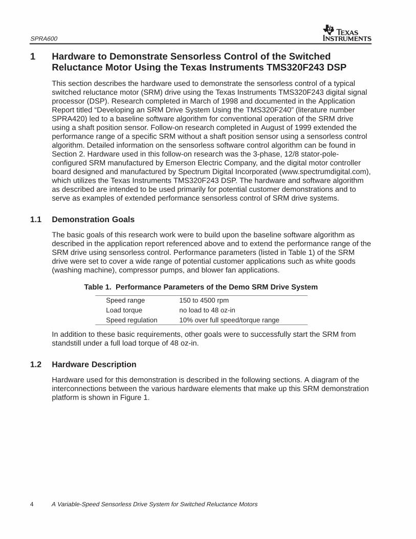
This section describes the hardware used to demonstrate the sensorless control of a typicalswitched reluctance motor (SRM) drive using the Texas Instruments TMS320F243 digital signalprocessor (DSP). Research completed in March of 1998 and documented in the ApplicationReport titled “Developing an SRM Drive System Using the TMS320F240” (literature numberSPRA420) led to a baseline software algorithm for conventional operation of the SRM driveusing a shaft position sensor. Follow-on research completed in August of 1999 extended theperformance range of a specific SRM without a shaft position sensor using a sensorless controlalgorithm. Detailed information on the sensorless software control algorithm can be found inSection 2. Hardware used in this follow-on research was the 3-phase, 12/8 stator-pole-configured SRM manufactured by Emerson Electric Company, and the digital motor controllerboard designed and manufactured by Spectrum Digital Incorporated (www.spectrumdigital.com),which utilizes the Texas Instruments TMS320F243 DSP. The hardware and software algorithmas described are intended to be used primarily for potential customer demonstrations and toserve as examples of extended performance sensorless control of SRM drive systems.
1.1 Demonstration Goals
The basic goals of this research work were to build upon the baseline software algorithm asdescribed in the application report referenced above and to extend the performance range of theSRM drive using sensorless control. Performance parameters (listed in Table 1) of the SRMdrive were set to cover a wide range of potential customer applications such as white goods(washing machine), compressor pumps, and blower fan applications.
Table 1. Performance Parameters of the Demo SRM Drive System
Speed range 150 to 4500 rpm
Load torque no load to 48 oz-in
Speed regulation 10% over full speed/torque range
In addition to these basic requirements, other goals were to successfully start the SRM fromstandstill under a full load torque of 48 oz-in.
1.2 Hardware Description
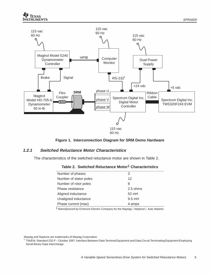
Hardware used for this demonstration is described in the following sections. A diagram of theinterconnections between the various hardware elements that make up this SRM demonstrationplatform is shown in Figure 1.
SPRA600
5 A Variable-Speed Sensorless Drive System for Switched Reluctance Motors
115 vac60 Hz
115 vac60 Hz
115 vac60 Hz
Magtrol Model 5240Dynamometer
Controller
MagtrolModel HD-705-6Dynamometer
50 in-lb
FlexCoupler
SRM phase U
Spectrum Digital Inc.Digital Motor
Controller
phase V
phase W
ComputerMonitor
Spectrum Digital Inc.TMS320F243 EVM
115 vac60 Hz
RibbonCable
+24 vdc +5 vdc
RS-232†
HPIBDual Power
Supply
SignalBrake
Figure 1. Interconnection Diagram for SRM Demo Hardware
1.2.1 Switched Reluctance Motor Characteristics
The characteristics of the switched reluctance motor are shown in Table 2.
Table 2. Switched Reluctance Motor ‡ Characteristics
Number of phases 3
Number of stator poles 12
Number of rotor poles 8
Phase resistance 2.5 ohms
Aligned inductance 52 mH
Unaligned inductance 9.5 mH
Phase current (max) 4 amps‡ Manufactured by Emerson Electric Company for the Maytag Neptune Auto Washer.
Maytag and Neptune are trademarks of Maytag Corporation.† TIA/EIA Standard 232-F – October 1997, Interface Between Data Terminal Equipment and Data Circuit-Terminating Equipment Employing
Serial Binary Data Interchange.
SPRA600
6 A Variable-Speed Sensorless Drive System for Switched Reluctance Motors
1.2.2 Digital Motor Controller
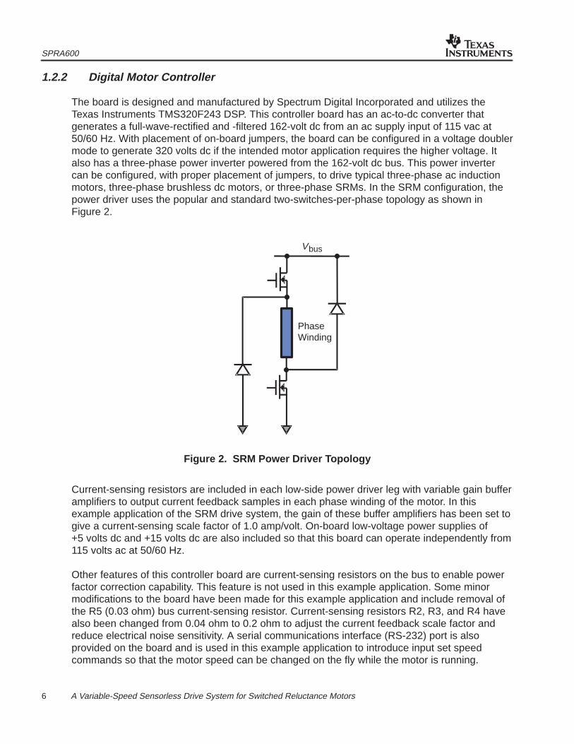
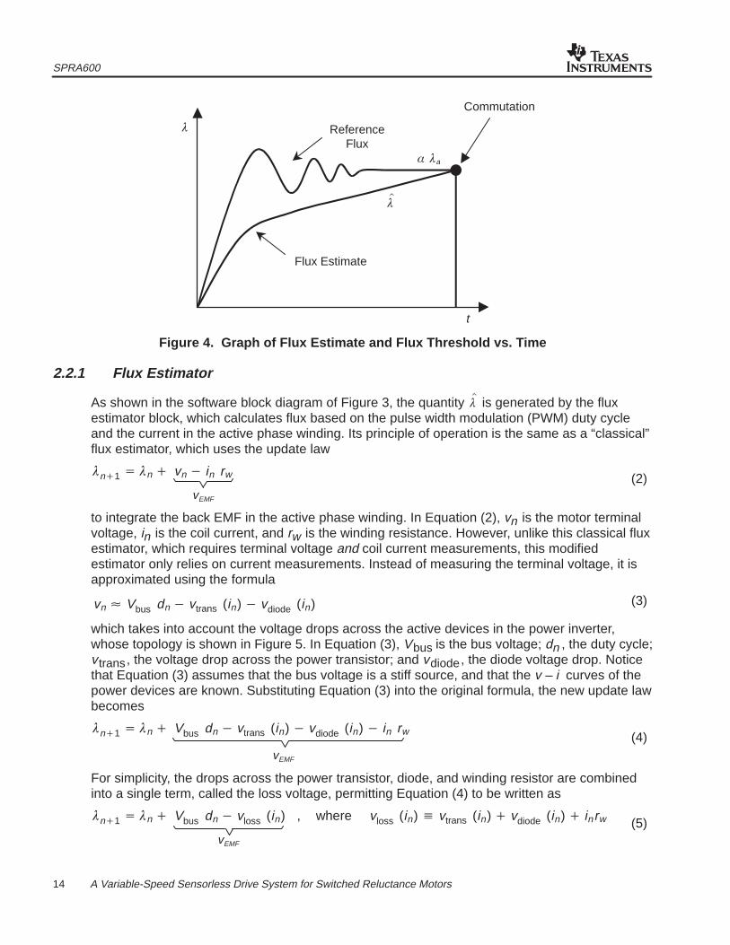
The board is designed and manufactured by Spectrum Digital Incorporated and utilizes theTexas Instruments TMS320F243 DSP. This controller board has an ac-to-dc converter thatgenerates a full-wave-rectified and -filtered 162-volt dc from an ac supply input of 115 vac at50/60 Hz. With placement of on-board jumpers, the board can be configured in a voltage doublermode to generate 320 volts dc if the intended motor application requires the higher voltage. Italso has a three-phase power inverter powered from the 162-volt dc bus. This power invertercan be configured, with proper placement of jumpers, to drive typical three-phase ac inductionmotors, three-phase brushless dc motors, or three-phase SRMs. In the SRM configuration, thepower driver uses the popular and standard two-switches-per-phase topology as shown inFigure 2.
PhaseWinding
Vbus
Figure 2. SRM Power Driver Topology
Current-sensing resistors are included in each low-side power driver leg with variable gain bufferamplifiers to output current feedback samples in each phase winding of the motor. In thisexample application of the SRM drive system, the gain of these buffer amplifiers has been set togive a current-sensing scale factor of 1.0 amp/volt. On-board low-voltage power supplies of+5 volts dc and +15 volts dc are also included so that this board can operate independently from115 volts ac at 50/60 Hz.
Other features of this controller board are current-sensing resistors on the bus to enable powerfactor correction capability. This feature is not used in this example application. Some minormodifications to the board have been made for this example application and include removal ofthe R5 (0.03 ohm) bus current-sensing resistor. Current-sensing resistors R2, R3, and R4 havealso been changed from 0.04 ohm to 0.2 ohm to adjust the current feedback scale factor andreduce electrical noise sensitivity. A serial communications interface (RS-232) port is alsoprovided on the board and is used in this example application to introduce input set speedcommands so that the motor speed can be changed on the fly while the motor is running.
SPRA600
7 A Variable-Speed Sensorless Drive System for Switched Reluctance Motors
1.2.3 TMS320F243 Evaluation Module
This evaluation module (EVM), based upon the Texas Instruments TMS320F243 digital signalprocessor, is designed and manufactured by Spectrum Digital Incorporated. It is an excellentplatform to develop and run software on the ’F24x family of processors and was usedextensively in the development and testing of the software algorithm for the sensorless control ofthe SRM drive system in this demonstration hardware. Key features of the TMS320F243 EVMare:
• 544 words of on-chip data memory
• 28K words of onboard memory
• on-chip FLASH memory
• on-chip UART
• MP7680 four-channel digital-to-analog converter
• 5-volt-only operation
(For additional information, see the Technical Reference on this TMS320F243 EVM published bySpectrum Digital Incorporated in 1998.)
To operate the demonstration as described in the operational procedures section, the sensorlesscontrol software must be embedded in the TMS320F243 DSP. (For details on embedding thesoftware in FLASH, please refer to the TMS320F20x/F24x DSP Embedded Flash MemoryTechnical Reference, literature number SPRU282.)
1.2.4 Magtrol Dynamometer
The dynamometer used to control load torque on the SRM in this demonstration hardwareplatform is manufactured by Magtrol Incorporated. It is a load cell dynamometer (model 705-6)that features a hysteresis brake for precise torque loading up to a maximum of 50.0 in-lb oftorque and has a maximum speed capability of 10,000 RPM. Power rating for the model 705-6dynamometer is 300 watts continuous and 1400 watts for less than five minutes. To achieve thebest accuracy capability of 0.25%, attention must be given to the calibration of the unit for zerooffset and scale factor as specified in the user’s manual. The motor shaft is attached to thedynamometer through a precision aligned flexible coupling that has been custom modified forthis demonstration platform. Alignment of the motor shaft through the flexible coupling is criticalto prevent vibration and mechanical induced noise at higher operation speeds above 2500 RPM.This type of flexible couplers can be obtained through Magtrol Incorporated.

SPRA600
8 A Variable-Speed Sensorless Drive System for Switched Reluctance Motors
1.2.5 Dynamometer Controller
Control of the dynamometer is provided by a Magtrol model 5240 controller that is aspeed-controlled power supply, designed to interface with any type of IBM-compatible computerusing an IEEE-488† general-purpose interface bus (GPIB) instrument controller. The model5240 controller can be used to control any Magtrol Load Cell Dynamometer. In addition, it canbe set to return torque-speed data to the computer when used with appropriate computersoftware. In this demonstration hardware, testing of the SRM performance was accomplishedwith an automatic-motor-testing software (M-TEST, version 2.03) provided by Magtrol.
1.3 Operational Procedures
To operate the demonstration, a serial communications link must be established between the’F243 and the host PC by using a standard RS-232 through-pin serial cable. This cable isattached to the DB9 connector on the Spectrum Digital board and the COM port on the PC.
WARNING:Do not use the DB9 connector on the EVM board. This connector is not isolated, andignoring this warning could result in hardware damage, injury, or even death.
Commands can be issued through a terminal program such as a Hyperterm, which is included inthe Windows operating system. To properly configure Hyperterm, the connection speed mustbe set at 19,200 baud, with 7 data bits, odd parity, and 1 stop bit, and all flow control must bedisabled.
With the connection established, the demonstration rig can be turned on, using the followingprocedure:
1. Power up the PC, load controller, and dynamometer brake.
2. Run the terminal program and the Magtrol M-TEST software.
3. Turn on the dual power supply.
4. Plug in the bus supply line on the Spectrum Digital board.
Once power has been applied to all of the components, the terminal program can be used toissue the ‘turn on’ command, which is ‘>t’ followed by a carriage return. When the EVM receivesthe ‘turn on’ command, the ’F243 injects an alignment current into phase 2. After the shaft hassettled at the aligned position, the ’F243 begins commutating the motor, causing it to spool up inthe counterclockwise direction to its initial target speed of 1000 RPM. At this point, the ’F243 isready to receive new commands, which are summarized in Table 3.
Windows is a registered trademark of Microsoft Corporation.† ANSI/IEEE Standard 488.1 – 1987, IEEE Standard Digital Interface for Programmable Instrumentation.
SPRA600
9 A Variable-Speed Sensorless Drive System for Switched Reluctance Motors
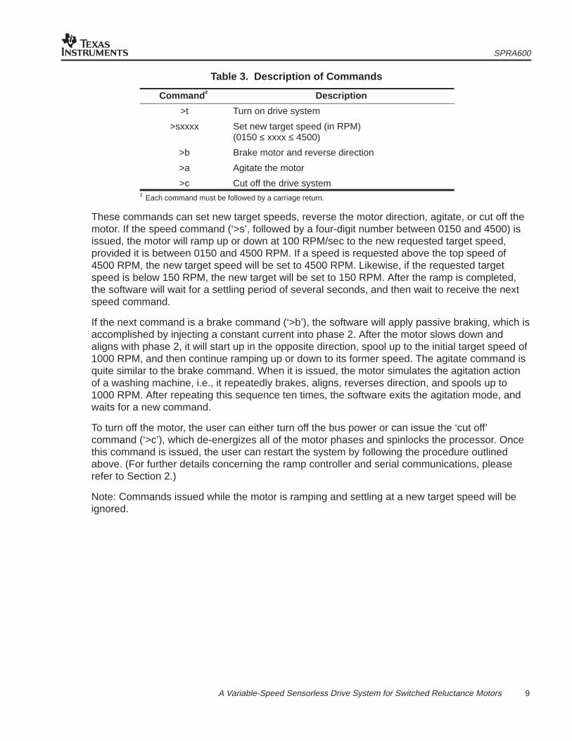
Table 3. Description of Commands
Command † Description
>t Turn on drive system
>sxxxx Set new target speed (in RPM)(0150 ≤ xxxx ≤ 4500)
>b Brake motor and reverse direction
>a Agitate the motor
>c Cut off the drive system† Each command must be followed by a carriage return.
These commands can set new target speeds, reverse the motor direction, agitate, or cut off themotor. If the speed command (‘>s’, followed by a four-digit number between 0150 and 4500) isissued, the motor will ramp up or down at 100 RPM/sec to the new requested target speed,provided it is between 0150 and 4500 RPM. If a speed is requested above the top speed of4500 RPM, the new target speed will be set to 4500 RPM. Likewise, if the requested targetspeed is below 150 RPM, the new target will be set to 150 RPM. After the ramp is completed,the software will wait for a settling period of several seconds, and then wait to receive the nextspeed command.
If the next command is a brake command (‘>b’), the software will apply passive braking, which isaccomplished by injecting a constant current into phase 2. After the motor slows down andaligns with phase 2, it will start up in the opposite direction, spool up to the initial target speed of1000 RPM, and then continue ramping up or down to its former speed. The agitate command isquite similar to the brake command. When it is issued, the motor simulates the agitation actionof a washing machine, i.e., it repeatedly brakes, aligns, reverses direction, and spools up to1000 RPM. After repeating this sequence ten times, the software exits the agitation mode, andwaits for a new command.
To turn off the motor, the user can either turn off the bus power or can issue the ‘cut off’command (‘>c’), which de-energizes all of the motor phases and spinlocks the processor. Oncethis command is issued, the user can restart the system by following the procedure outlinedabove. (For further details concerning the ramp controller and serial communications, pleaserefer to Section 2.)
Note: Commands issued while the motor is ramping and settling at a new target speed will beignored.
SPRA600
10 A Variable-Speed Sensorless Drive System for Switched Reluctance Motors
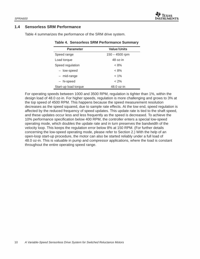
1.4 Sensorless SRM Performance
Table 4 summarizes the performance of the SRM drive system.
Table 4. Sensorless SRM Performance Summary
Parameter Value/Units
Speed range 150 – 4500 rpm
Load torque 48 oz-in
Speed regulation < 8%
– low-speed < 8%
– mid-range < 1%
– hi-speed < 2%
Start-up load torque 48.0 oz-in
For operating speeds between 1000 and 3500 RPM, regulation is tighter than 1%, within thedesign load of 48.0 oz-in. For higher speeds, regulation is more challenging and grows to 3% atthe top speed of 4500 RPM. This happens because the speed measurement resolutiondecreases as the speed squared, due to sample rate effects. At the low end, speed regulation isaffected by the reduced frequency of speed updates. This update rate is tied to the shaft speed,and these updates occur less and less frequently as the speed is decreased. To achieve the10% performance specification below 400 RPM, the controller enters a special low-speedoperating mode, which doubles the update rate and in turn preserves the bandwidth of thevelocity loop. This keeps the regulation error below 8% at 150 RPM. (For further detailsconcerning the low-speed operating mode, please refer to Section 2.) With the help of anopen-loop start-up procedure, the motor can also be started reliably under a full load of48.0 oz-in. This is valuable in pump and compressor applications, where the load is constantthroughout the entire operating speed range.
SPRA600
11 A Variable-Speed Sensorless Drive System for Switched Reluctance Motors
2 Control Software for a Sensorless SRM Drive System
This section describes the control software for a sensorless SRM drive system using theTMS320F243 DSP. The drive system is intended for demonstration purposes and is composedof a TMS320F243 evaluation module (EVM); a digital motor controller board available fromSpectrum Digital Incorporated; a 3-phase, 12/8 stator-pole-configured 0.40-HP SRMmanufactured by Emerson Electric Company; and a Magtrol 50.0 lb-ft dynamometer and loadcontroller. (For further details concerning the hardware and performance specifications for thisdrive system, refer to Section 1.)
The control software features a flux-based sensorless algorithm for 3-phase SRMs operating on170 V of bus voltage and up to 4.0 A of phase current. The algorithm is capable of two quadrantspeed control between 150 and 4500 RPM, with better than 8% speed regulation (<1% between1000 and 3500 RPM), and reliable start-up under a design load of 48.0 oz-in. An RS-232 seriallink permits users to issue commands from a host PC to turn on, cut off, and change motorspeed and the direction of rotation on the fly. This software can be launched via the EVM’s JTAGport using a XDS510PP emulator board inline with a SPI 110 optoisolator or the software canbe directly embedded in the EVM’s FLASH memory. (For further details on FLASHprogramming, refer to the TMS320F20x/F24x DSP Embedded FLASH Memory TechnicalReference, literature number SPRU282.)
2.1 Overview of the Sensorless SRM Control Software
The software for the sensorless drive system is written primarily in C, with the exception of a fewassembly language subroutines for high-speed computations. The code fits into theTMS320F243’s 8K of FLASH program memory and the DSP’s internal RAM blocks, andrequires no external memory. It consumes about 6K of program memory and 300 words of datamemory. To execute the code on a TMS320C242 DSP controller, the program storagerequirements can be reduced to less than 4K by replacing the look-up tables used by thecommutation algorithm with polynomial interpolating functions.
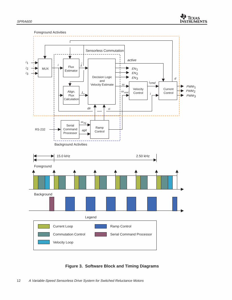
As shown in Figure 3, the software is composed of five key modules: an algorithm for sensorlesscommutation, an outer loop for velocity control, an inner loop for current control, a serialcommand processor, and a ramp controller. The first three of these modules execute in theforeground. They are called from a timer interrupt service routine (ISR), which is fired every66.7 µsec (15.0 kHz) by a free-running onboard timer. As shown in the timing diagram ofFigure 3, the commutation controller and current control loop execute every interrupt cycle (at15.0 kHz), while the velocity loop only executes every sixth interrupt cycle (at 2.5 kHz).
XDS510PP is a trademark of Texas Instruments Incorporated.
SPRA600
12 A Variable-Speed Sensorless Drive System for Switched Reluctance Motors
active
Foreground Activities
Sensorless Commutation
i1
i2i3
MUXFlux
Estimator
i ��
Decision Logicand
Velocity Estimate
EN1
EN3
EN2
VelocityControl
icmd
i
d
PWM1PWM2PWM3
CurrentControl
RampControl
SerialCommandProcessor
RS-232
��
�trg
agit
Align.Flux
Calculation
�cmd
�
�dir
Background Activities
15.0 kHz 2.50 kHz
Foreground
Background
Legend
Current Loop
Commutation Control
Velocity Loop
Ramp Control
Serial Command Processor
Figure 3. Software Block and Timing Diagrams
SPRA600
13 A Variable-Speed Sensorless Drive System for Switched Reluctance Motors
The execution time of each foreground activity shown in the software block diagram is listed inTable 5.
Table 5. Execution Times of Foreground Activity
Activity Execution Time ( µsec)
Flux Estimator 8.3
Sensorless Commutation 15.5 to 34.8
Current Control Loop 10.6
Velocity Control Loop 11.3
Note that execution time of the sensorless commutation algorithm varies. If the motor needs toswitch phases and perform a velocity update, the run time will be 34.8 µsec; otherwise, the runtime will be 15.5 µsec.
Overall, execution time of the ISR varies from 34.4 µsec to 53.2 µsec, depending on whichactivities must execute. On average, the interrupt service routine utilizes 55% of the processingtime, leaving the remaining 45% for the background loop, which includes a serial commandprocessor and ramp speed controller.
2.2 Sensorless Commutation and Velocity-Update Algorithm
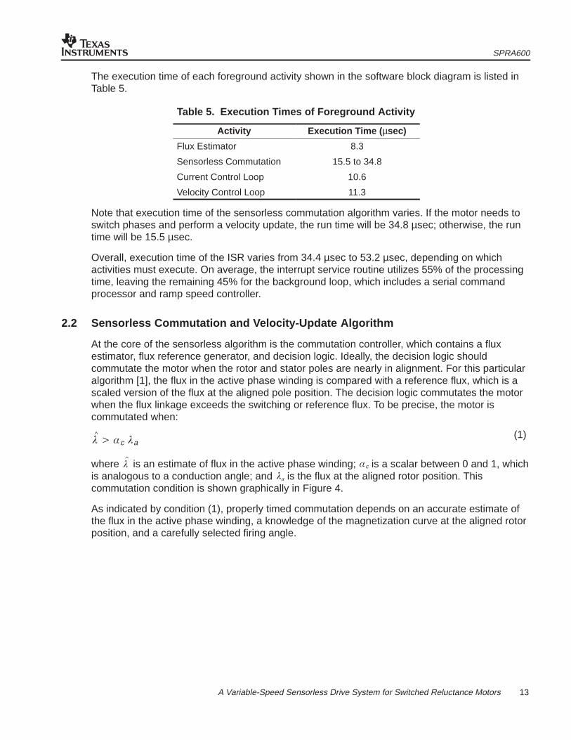
At the core of the sensorless algorithm is the commutation controller, which contains a fluxestimator, flux reference generator, and decision logic. Ideally, the decision logic shouldcommutate the motor when the rotor and stator poles are nearly in alignment. For this particularalgorithm [1], the flux in the active phase winding is compared with a reference flux, which is ascaled version of the flux at the aligned pole position. The decision logic commutates the motorwhen the flux linkage exceeds the switching or reference flux. To be precise, the motor iscommutated when:
�^� �c �a
where ��
is an estimate of flux in the active phase winding; �c is a scalar between 0 and 1, whichis analogous to a conduction angle; and �� is the flux at the aligned rotor position. Thiscommutation condition is shown graphically in Figure 4.
As indicated by condition (1), properly timed commutation depends on an accurate estimate ofthe flux in the active phase winding, a knowledge of the magnetization curve at the aligned rotorposition, and a carefully selected firing angle.
(1)
SPRA600
14 A Variable-Speed Sensorless Drive System for Switched Reluctance Motors
ReferenceFlux
Commutation
t
Flux Estimate
�
��
� �a
Figure 4. Graph of Flux Estimate and Flux Threshold vs. Time
2.2.1 Flux Estimator
As shown in the software block diagram of Figure 3, the quantity ��
is generated by the fluxestimator block, which calculates flux based on the pulse width modulation (PWM) duty cycleand the current in the active phase winding. Its principle of operation is the same as a “classical”flux estimator, which uses the update law
�n�1� �n� vn� in rw
vEMF
to integrate the back EMF in the active phase winding. In Equation (2), vn is the motor terminalvoltage, in is the coil current, and rw is the winding resistance. However, unlike this classical fluxestimator, which requires terminal voltage and coil current measurements, this modifiedestimator only relies on current measurements. Instead of measuring the terminal voltage, it isapproximated using the formula
vn� Vbus dn� vtrans (in)� vdiode (in)
which takes into account the voltage drops across the active devices in the power inverter,whose topology is shown in Figure 5. In Equation (3), Vbus is the bus voltage; dn , the duty cycle;vtrans, the voltage drop across the power transistor; and vdiode, the diode voltage drop. Noticethat Equation (3) assumes that the bus voltage is a stiff source, and that the v – i curves of thepower devices are known. Substituting Equation (3) into the original formula, the new update lawbecomes
�n�1� �n� Vbus dn� vtrans (in)� vdiode (in)� in rw
vEMF
For simplicity, the drops across the power transistor, diode, and winding resistor are combinedinto a single term, called the loss voltage, permitting Equation (4) to be written as
�n�1� �n� Vbus dn� vloss (in) , where vloss (in)� vtrans (in)� vdiode (in)� inrw
vEMF
(2)
(3)
(4)
(5)
SPRA600
15 A Variable-Speed Sensorless Drive System for Switched Reluctance Motors
With the “loss” voltage tabulated as a function of current, the update is performed in the softwarewith two additions, a scalar multiplication, and a single look-up operation. (For more informationon how to construct the voltage loss table, please refer to Section 3.)
PhaseWinding
Vbus
Figure 5. SRM Power Driver Topology
2.2.2 Flux Estimator Implementation
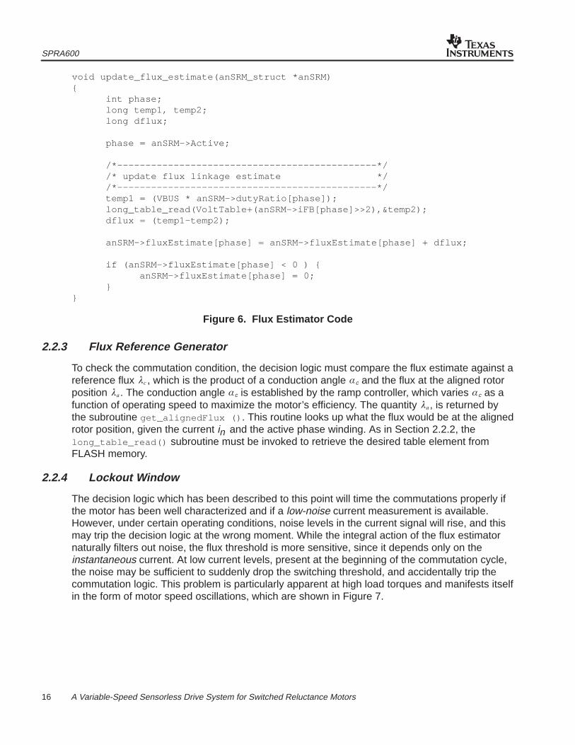
The subroutine update_flux_estimate() updates the flux estimate based on the duty cycleapplied to the PWM generator and the current measured in the active phase winding. As shownin Figure 6, the code implements Equation (5) in a straightforward manner, with the exception ofthe look-up operation. To perform the look-up operation, an index into the 256-point table isgenerated by shifting in , a 10-bit unsigned integer, two places to the right. The address of thedesired table element is formed by adding this index to the table’s base address, and the table isaccessed by invoking the assembly language subroutine long_table_read() . This subroutinereads the desired table element from FLASH program memory using a table-read operation(TLBR) and returns the value in a desired data memory address. After completing the table read,both terms in Equation (5) are added to the previous flux estimate to form the new one, and theupdate is stored in the SRM data structure. This update is a scaled version of actual flux linkagein the winding. To convert it to physical units of V-sec, multiply by the following scale factor:
�^�
1000� 15000
anSRM –> fluxEstimate
In Equation (6), the factor of 1000 reflects the fact that the actual volts have been scaled by themaximum duty cycle count of 1000, and the factor of 15,000 reflects the fact that the time-step of66.7 µsec has been omitted from the integration.
(6)
SPRA600
16 A Variable-Speed Sensorless Drive System for Switched Reluctance Motors
void update_flux_estimate(anSRM_struct *anSRM){
int phase; long temp1, temp2; long dflux;
phase = anSRM–>Active;
/*––––––––––––––––––––––––––––––––––––––––––––––*//* update flux linkage estimate *//*––––––––––––––––––––––––––––––––––––––––––––––*/
temp1 = (VBUS * anSRM–>dutyRatio[phase]);long_table_read(VoltTable+(anSRM–>iFB[phase]>>2),&temp2);dflux = (temp1–temp2);
anSRM–>fluxEstimate[phase] = anSRM–>fluxEstimate[phase] + dflux;
if (anSRM–>fluxEstimate[phase] < 0 ) {anSRM–>fluxEstimate[phase] = 0;
}}
Figure 6. Flux Estimator Code
2.2.3 Flux Reference Generator
To check the commutation condition, the decision logic must compare the flux estimate against areference flux �� , which is the product of a conduction angle �c and the flux at the aligned rotorposition ��. The conduction angle �c is established by the ramp controller, which varies �c as afunction of operating speed to maximize the motor’s efficiency. The quantity ��, is returned bythe subroutine get_alignedFlux () . This routine looks up what the flux would be at the alignedrotor position, given the current in and the active phase winding. As in Section 2.2.2, thelong_table_read() subroutine must be invoked to retrieve the desired table element fromFLASH memory.
2.2.4 Lockout Window
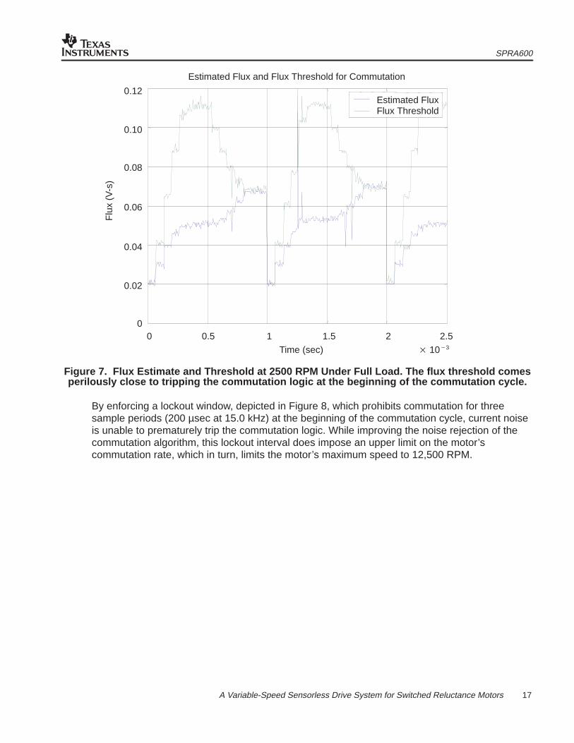
The decision logic which has been described to this point will time the commutations properly ifthe motor has been well characterized and if a low-noise current measurement is available.However, under certain operating conditions, noise levels in the current signal will rise, and thismay trip the decision logic at the wrong moment. While the integral action of the flux estimatornaturally filters out noise, the flux threshold is more sensitive, since it depends only on theinstantaneous current. At low current levels, present at the beginning of the commutation cycle,the noise may be sufficient to suddenly drop the switching threshold, and accidentally trip thecommutation logic. This problem is particularly apparent at high load torques and manifests itselfin the form of motor speed oscillations, which are shown in Figure 7.
SPRA600
17 A Variable-Speed Sensorless Drive System for Switched Reluctance Motors
Flu
x (V
-s)
Time (sec)
0.12
0.10
0.08
0.06
0.04
0.02
00 0.5 1.5 2.51 2
� 10�3
Estimated Flux and Flux Threshold for Commutation
Estimated FluxFlux Threshold
Figure 7. Flux Estimate and Threshold at 2500 RPM Under Full Load. The flux threshold comesperilously close to tripping the commutation logic at the beginning of the commutation cycle.
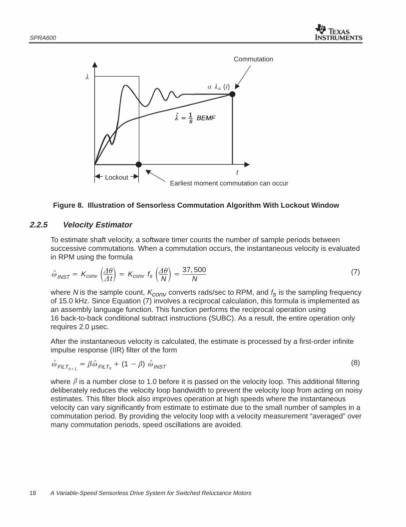
By enforcing a lockout window, depicted in Figure 8, which prohibits commutation for threesample periods (200 µsec at 15.0 kHz) at the beginning of the commutation cycle, current noiseis unable to prematurely trip the commutation logic. While improving the noise rejection of thecommutation algorithm, this lockout interval does impose an upper limit on the motor’scommutation rate, which in turn, limits the motor’s maximum speed to 12,500 RPM.
SPRA600
18 A Variable-Speed Sensorless Drive System for Switched Reluctance Motors
Commutation
�
LockoutEarliest moment commutation can occur
�^� 1
s BEMF�^� 1
s BEMF
� �a (i )
t
Figure 8. Illustration of Sensorless Commutation Algorithm With Lockout Window
2.2.5 Velocity Estimator
To estimate shaft velocity, a software timer counts the number of sample periods betweensuccessive commutations. When a commutation occurs, the instantaneous velocity is evaluatedin RPM using the formula
�^ INST � Kconv ����t� � Kconv fs ���N � �
37, 500N
where N is the sample count, Kconv converts rads/sec to RPM, and fs is the sampling frequencyof 15.0 kHz. Since Equation (7) involves a reciprocal calculation, this formula is implemented asan assembly language function. This function performs the reciprocal operation using16 back-to-back conditional subtract instructions (SUBC). As a result, the entire operation onlyrequires 2.0 µsec.
After the instantaneous velocity is calculated, the estimate is processed by a first-order infiniteimpulse response (IIR) filter of the form
�^ FILTn�1� ��^ FILTn
� (1� �) �^ INST
where � is a number close to 1.0 before it is passed on the velocity loop. This additional filteringdeliberately reduces the velocity loop bandwidth to prevent the velocity loop from acting on noisyestimates. This filter block also improves operation at high speeds where the instantaneousvelocity can vary significantly from estimate to estimate due to the small number of samples in acommutation period. By providing the velocity loop with a velocity measurement “averaged” overmany commutation periods, speed oscillations are avoided.
(7)
(8)
SPRA600
19 A Variable-Speed Sensorless Drive System for Switched Reluctance Motors
2.2.6 Stall Detector
If the instantaneous shaft velocity drops below 60 RPM after the motor startup has completed, astall detector in the decision logic will engage. After the logic detects a stalled condition, it calls asubroutine which immediately cuts off the motor. This routine sets all PWM generator dutycycles to zero, switches off the lowside power transistors, zeroes out all of the desired currents,illuminates all LEDs on the EVM board, and goes into an infinite loop. A processor reset isrequired to restart the system. This safety feature prevents the motor from overheating if theshaft suddenly becomes locked in place.
2.2.7 Low-Speed Operating Mode (<400 RPM)
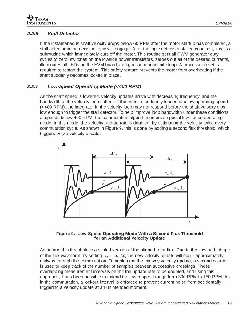
As the shaft speed is lowered, velocity updates arrive with decreasing frequency, and thebandwidth of the velocity loop suffers. If the motor is suddenly loaded at a low operating speed(<400 RPM), the integrator in the velocity loop may not respond before the shaft velocity dipslow enough to trigger the stall detector. To help improve loop bandwidth under these conditions,at speeds below 400 RPM, the commutation algorithm enters a special low-speed operatingmode. In this mode, the velocity-update rate is doubled, by estimating the velocity twice everycommutation cycle. As shown in Figure 9, this is done by adding a second flux threshold, whichtriggers only a velocity update.
�
�tm
t
�c �a
�tc
�c �a
�m �a�m �a
��
��
Figure 9. Low-Speed Operating Mode With a Second Flux Thresholdfor an Additional Velocity Update
As before, this threshold is a scaled version of the aligned rotor flux. Due to the sawtooth shapeof the flux waveform, by setting �m � �c �2, the new velocity update will occur approximatelymidway through the commutation. To implement the midway velocity update, a second counteris used to keep track of the number of samples between successive crossings. Theseoverlapping measurement intervals permit the update rate to be doubled, and using thisapproach, it has been possible to extend the lower speed range from 300 RPM to 150 RPM. Asin the commutation, a lockout interval is enforced to prevent current noise from accidentallytriggering a velocity update at an unintended moment.
SPRA600
20 A Variable-Speed Sensorless Drive System for Switched Reluctance Motors
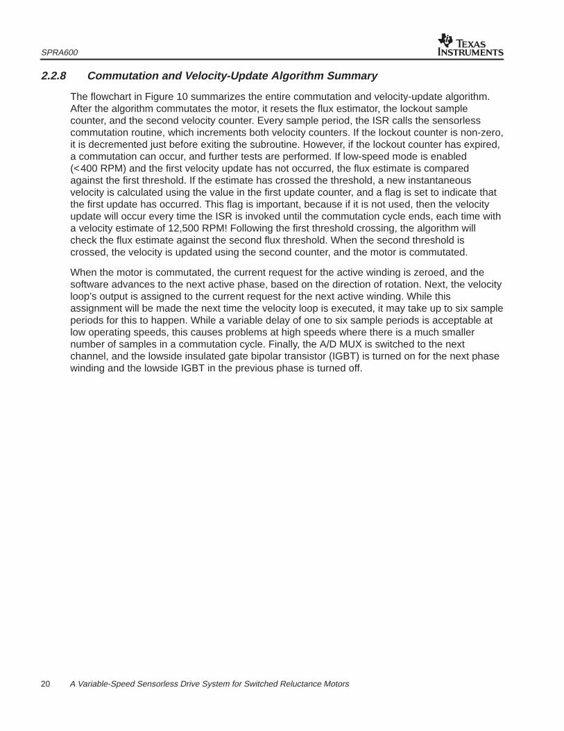
2.2.8 Commutation and Velocity-Update Algorithm Summary
The flowchart in Figure 10 summarizes the entire commutation and velocity-update algorithm.After the algorithm commutates the motor, it resets the flux estimator, the lockout samplecounter, and the second velocity counter. Every sample period, the ISR calls the sensorlesscommutation routine, which increments both velocity counters. If the lockout counter is non-zero,it is decremented just before exiting the subroutine. However, if the lockout counter has expired,a commutation can occur, and further tests are performed. If low-speed mode is enabled(<400 RPM) and the first velocity update has not occurred, the flux estimate is comparedagainst the first threshold. If the estimate has crossed the threshold, a new instantaneousvelocity is calculated using the value in the first update counter, and a flag is set to indicate thatthe first update has occurred. This flag is important, because if it is not used, then the velocityupdate will occur every time the ISR is invoked until the commutation cycle ends, each time witha velocity estimate of 12,500 RPM! Following the first threshold crossing, the algorithm willcheck the flux estimate against the second flux threshold. When the second threshold iscrossed, the velocity is updated using the second counter, and the motor is commutated.
When the motor is commutated, the current request for the active winding is zeroed, and thesoftware advances to the next active phase, based on the direction of rotation. Next, the velocityloop’s output is assigned to the current request for the next active winding. While thisassignment will be made the next time the velocity loop is executed, it may take up to six sampleperiods for this to happen. While a variable delay of one to six sample periods is acceptable atlow operating speeds, this causes problems at high speeds where there is a much smallernumber of samples in a commutation cycle. Finally, the A/D MUX is switched to the nextchannel, and the lowside insulated gate bipolar transistor (IGBT) is turned on for the next phasewinding and the lowside IGBT in the previous phase is turned off.
SPRA600
21 A Variable-Speed Sensorless Drive System for Switched Reluctance Motors
�^� �m �a
Wait 1 Sample
First update counter++;Second update counter++
Lockout counter = 0
Lockout counter––
First update flag = 0 �^� �c �a
No
Update velocity using first update counter;Reset first update counter;Set first update flag
Reset flux estimator;Reset lockout counter;Reset first update flag;Update velocity using second update counter;Reset second counter;Commutate motor
Yes
Yes
Yes
YesNo
No
No
Figure 10. Commutation and Velocity-Update Flow Diagram
SPRA600
22 A Variable-Speed Sensorless Drive System for Switched Reluctance Motors
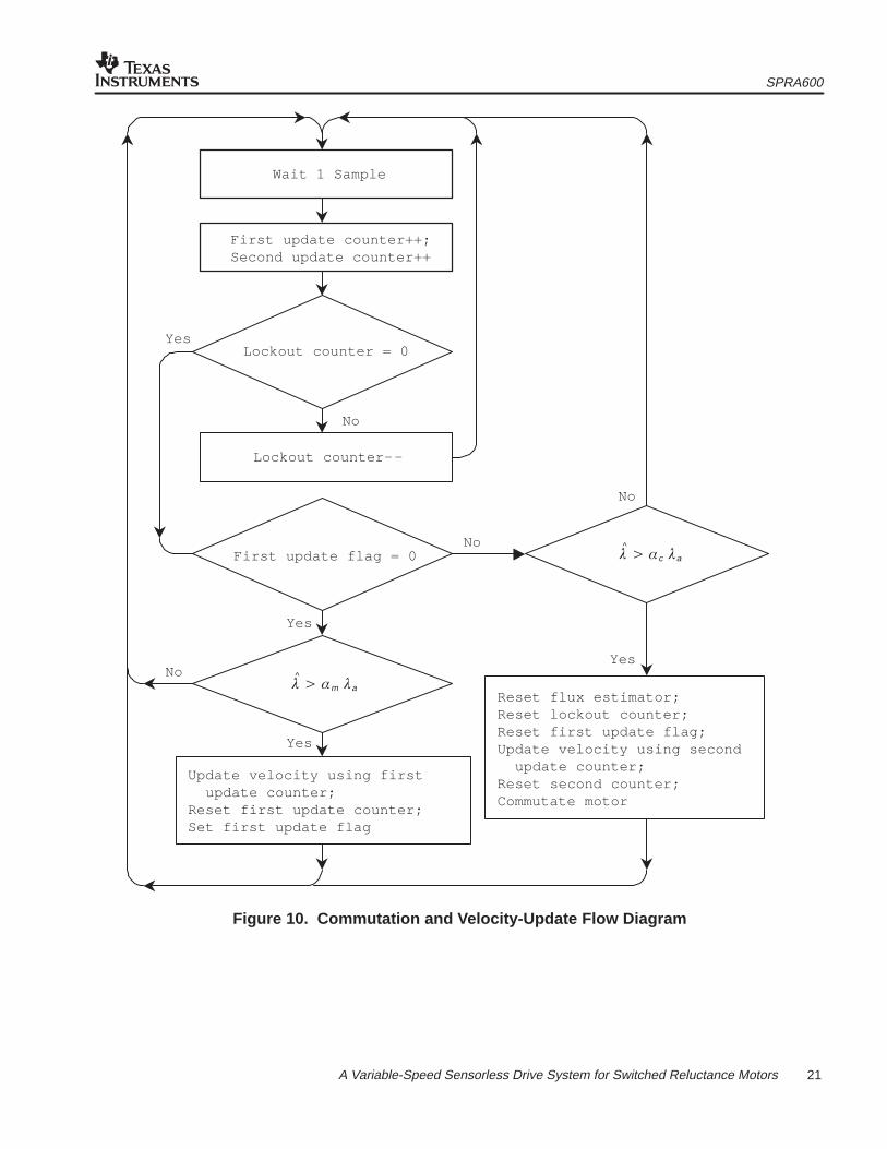
2.3 Velocity Loop
The velocity loop, which executes at a frequency of 2.50 kHz, employs a discretizedproportional-integral (PI) control law to control motor shaft speed. The proportional term in thecontrol law damps out speed oscillations and the integral term drives the DC speed errors tozero. As shown in the block diagram of Figure 11, for safety reasons, a windup limit of 6.25 A inthe positive direction and the same in the negative direction is imposed on the integrator. Inaddition, an upper and a lower current command limit are placed on the output of the velocityloop. The upper limit is imposed for safety reasons and varies with operating speed; the lowerpositive limit ensures that there is sufficient amount of current to make commutation decisions.
�cmd
�^
n
z�1
Ki
Kp
icmdn
Figure 11. Block Diagram of the Velocity Control Loop
2.3.1 Motor Start-up Under Load
When the motor is started under load, the software counters that gauge the time betweencommutations can roll over, corrupting the speed estimates, and causing the velocity loop tocommand an improper amount of current. When this happens, the motor may experiencestart-up hesitation, may start up in the wrong direction, or may even stall altogether. To solve thisproblem, the integrator in the velocity loop is given a large initial value, which exceeds thecurrent command limit. This causes the initial velocity estimates to be neglected and a largeamount of torque to be applied to the motor. In effect, the velocity controller runs open-loop.When the velocity estimates start to exceed the initial target velocity of 1000 RPM, the integratorbegins “unwinding” at a rate that depends on the difference between the estimated and desiredvelocity. As the integrator output decreases, eventually the velocity loop output falls below thecurrent command limit, and the velocity controller resumes closed-loop operation and regulatesthe speed to 1000 RPM.
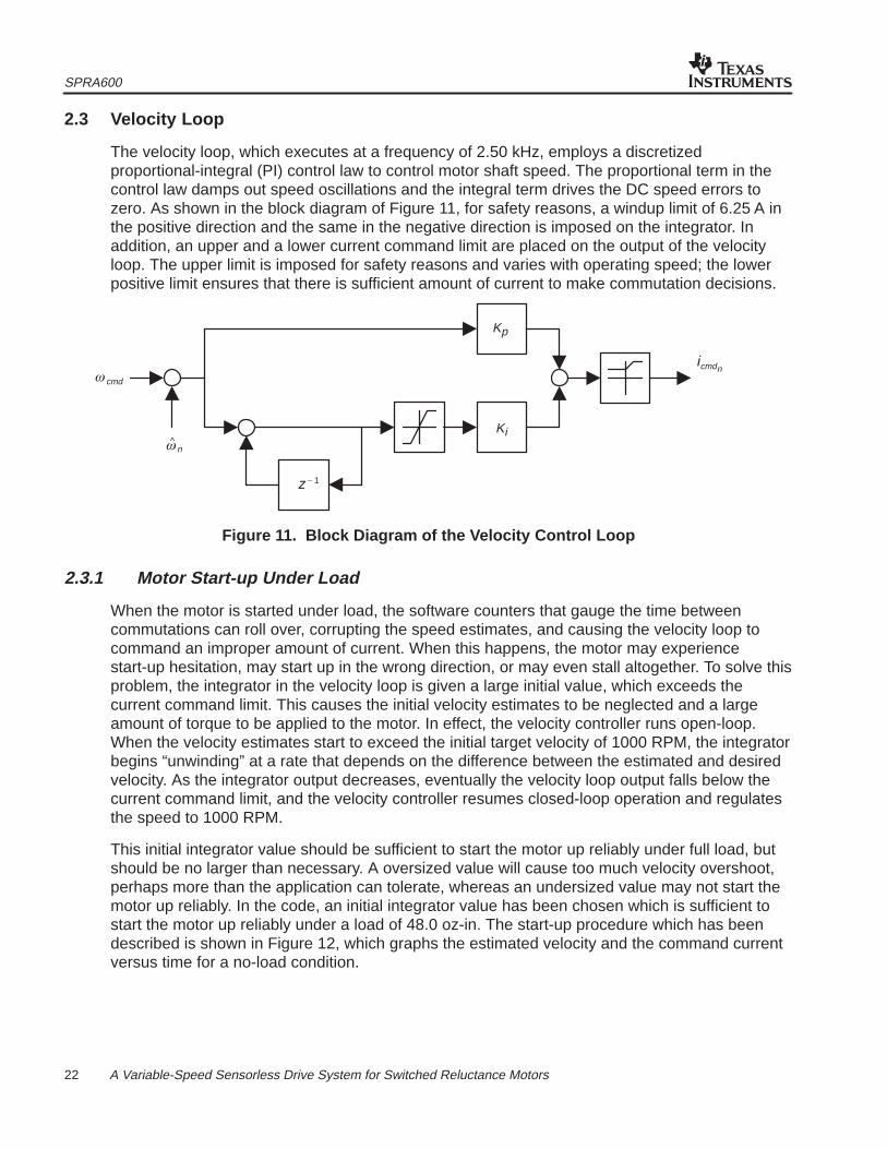
This initial integrator value should be sufficient to start the motor up reliably under full load, butshould be no larger than necessary. A oversized value will cause too much velocity overshoot,perhaps more than the application can tolerate, whereas an undersized value may not start themotor up reliably. In the code, an initial integrator value has been chosen which is sufficient tostart the motor up reliably under a load of 48.0 oz-in. The start-up procedure which has beendescribed is shown in Figure 12, which graphs the estimated velocity and the command currentversus time for a no-load condition.
SPRA600
23 A Variable-Speed Sensorless Drive System for Switched Reluctance Motors
Est
imat
ed V
eloc
ity (
RP
M)
Time (sec)
Vel
ocity
Loo
p O
utpu
t (A
)
0
1500
1000
500
00.5 1.51
0
1
2
3
4
5
0 0.5 1 1.5
Time (sec)
Figure 12. Instantaneous Velocity Estimate and Velocity Loop Output During Start-up
In Figure 12, it is evident that the velocity is overestimated immediately following start-up. Thiscauses a momentary drop in the integrator output from saturation, but the integrator winds upagain, the velocity controller saturates for approximately the first 0.50 seconds. Shortly afterreaching the initial target velocity, the integrator unwinds enough to bring the velocity controllerout of saturation, and the system resumes closed-loop operation. The velocity loop overshootsabout 30% under no-load conditions, but under the design load of 48.0 oz-in, the overshoot isless than 10%.
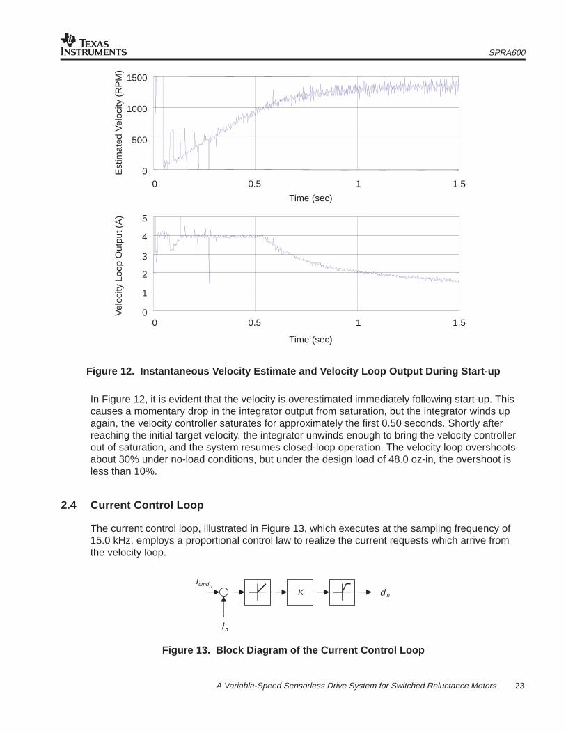
2.4 Current Control Loop
The current control loop, illustrated in Figure 13, which executes at the sampling frequency of15.0 kHz, employs a proportional control law to realize the current requests which arrive fromthe velocity loop.
icmdn
i n
K
i n
d n
Figure 13. Block Diagram of the Current Control Loop
SPRA600
24 A Variable-Speed Sensorless Drive System for Switched Reluctance Motors
Every sample period, the current controller reads the latest current sample and calculates thecurrent error, which is the difference between the measured and requested current. For positiveerrors, the controller calculates a duty cycle to the active PWM channel in proportion to the error.This calculated duty cycle becomes the applied one, provided that the calculated value is belowthe current command limit. Otherwise, the assigned duty cycle is the saturation limit. Thissaturation limit is set to 50% for start-up, but is relaxed to 90% after the motor reaches itssteady-state operating speed. A 100% duty cycle is never permitted, because the drivers needtime to refresh. For negative errors, the duty cycle is set to zero; this soft-chops the channel, andthe current decays until the error once again becomes positive.
2.5 Ramp Controller
The ramp controller receives speed and direction commands from the serial comms module andapplies the necessary sequence of commands to the commutation controller, velocity loop, andcurrent loop to achieve the new target speed and direction. It runs in the background as asoftware-state machine. After the motor has settled to a new target speed and direction, theramp controller enters its wait state. In this state, it continually checks with the serial commandprocessor to see if a new command has arrived across the RS-232 link.
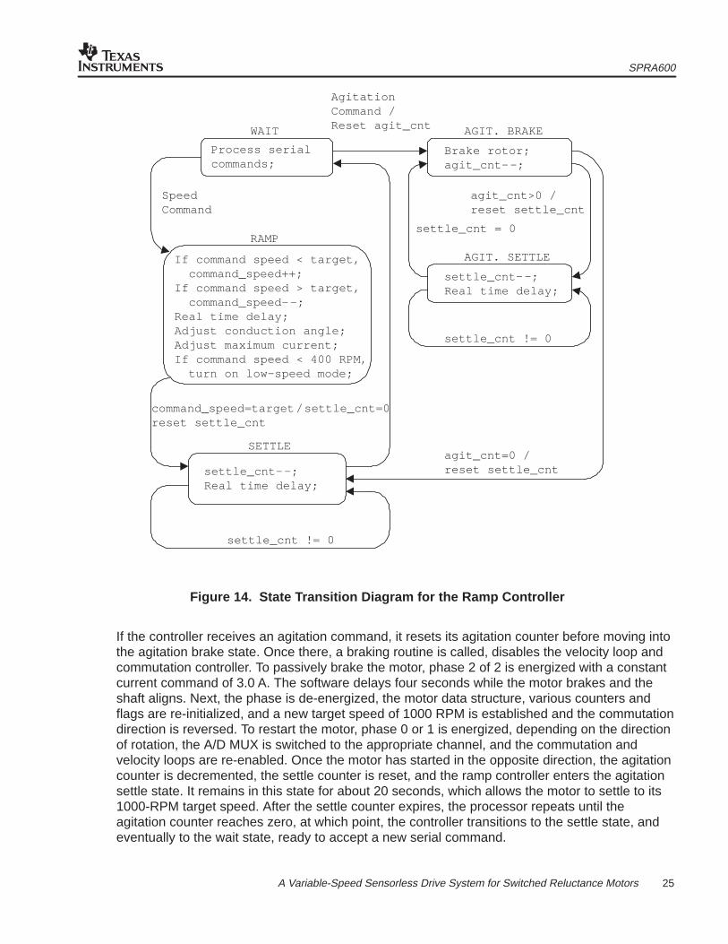
If a new target speed arrives, the ramp controller shifts into its ramp state, as shown in the statetransition diagram of Figure 14. Depending upon whether the new target speed is above orbelow the current operating speed, the ramp controller will either increment or decrement thecurrent command speed by 1 RPM. As the command speed is increased or decreased, theconduction angle is adjusted for efficient torque production and the current command limit is alsoadjusted. If the command speed falls below 400 RPM, the low-speed operating mode isactivated, which doubles the velocity-update rate. A real-time delay is also inserted, to ensurespecific ramp-up and ramp-down rates of 100 RPM/sec or 50 RPM/sec, respectively. The rampcontroller remains in this state until the command speed has reached the target speed. Whenthis happens, the controller resets the settle counter and transitions into the settle state. Thepurpose of this state is to allow any speed transients to die down before accepting any newtarget speeds from the serial command processor. The controller remains in the settle state untilthe counter expires, which happens after approximately two seconds. When the counter expires,the controller returns to the wait state, and awaits a new target speed.
SPRA600
25 A Variable-Speed Sensorless Drive System for Switched Reluctance Motors
WAIT AGIT. BRAKE
RAMP
AGIT. SETTLE
SETTLE
Process serialcommands;
SpeedCommand
If command speed < target,command_speed++;
If command speed > target,command_speed––;
Real time delay;Adjust conduction angle;Adjust maximum current;If command speed < 400 RPM,
turn on low-speed mode;
command_speed=target /settle_cnt=0reset settle_cnt
settle_cnt––;Real time delay;
settle_cnt != 0
Brake rotor;agit_cnt––;
agit_cnt>0 /reset settle_cnt
settle_cnt––;Real time delay;
settle_cnt != 0
agit_cnt=0 /reset settle_cnt
settle_cnt = 0
AgitationCommand /Reset agit_cnt
Figure 14. State Transition Diagram for the Ramp Controller
If the controller receives an agitation command, it resets its agitation counter before moving intothe agitation brake state. Once there, a braking routine is called, disables the velocity loop andcommutation controller. To passively brake the motor, phase 2 of 2 is energized with a constantcurrent command of 3.0 A. The software delays four seconds while the motor brakes and theshaft aligns. Next, the phase is de-energized, the motor data structure, various counters andflags are re-initialized, and a new target speed of 1000 RPM is established and the commutationdirection is reversed. To restart the motor, phase 0 or 1 is energized, depending on the directionof rotation, the A/D MUX is switched to the appropriate channel, and the commutation andvelocity loops are re-enabled. Once the motor has started in the opposite direction, the agitationcounter is decremented, the settle counter is reset, and the ramp controller enters the agitationsettle state. It remains in this state for about 20 seconds, which allows the motor to settle to its1000-RPM target speed. After the settle counter expires, the processor repeats until theagitation counter reaches zero, at which point, the controller transitions to the settle state, andeventually to the wait state, ready to accept a new serial command.
SPRA600
26 A Variable-Speed Sensorless Drive System for Switched Reluctance Motors
2.6 Serial Comms
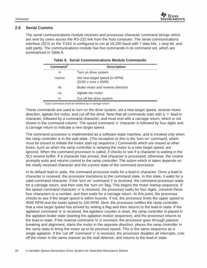
The serial communications module receives and processes character command strings whichare sent by users across the RS-232 link from the host computer. The serial communicationsinterface (SCI) on the ’F24X is configured to run at 19,200 baud with 7 data bits, 1 stop bit, andodd parity. The communications module has five commands in its command set, which aresummarized in Table 6.
Table 6. Serial Communications Module Commands
Command † Description
>t Turn on drive system
>sxxxx Set new target speed (in RPM)(0150 ≤ xxxx ≤ 4500)
>b Brake motor and reverse direction
>a Agitate the motor
>c Cut off the drive system† Each command must be followed by a carriage return.
These commands are used to turn on the drive system, set a new target speed, reverse motordirection, agitate the motor, and cut off the drive. Note that all commands start with a ‘>’ lead-incharacter, followed by a command character, and must end with a carriage return, which is notshown in the command column. The speed command ‘s’ character is followed by four digits anda carriage return to indicate a new target speed.
The command processor is implemented as a software-state machine, and is invoked only whenthe ramp controller is in the wait state. (The exception to this is the ‘turn on’ command, whichmust be issued to initiate the motor start-up sequence.) Commands which are issued at othertimes, such as when the ramp controller is ramping the motor to a new target speed, areignored. When the command processor is called, it checks to see if a character is waiting in theSCI receive buffer. If a character has arrived, that character is processed; otherwise, the routinepromptly exits and returns control to the ramp controller. The action which is taken depends onthe newly received character and the current state of the command processor.
In its default lead-in state, the command processor waits for a lead-in character. Once a lead-incharacter is received, the processor transitions to the command state. In this state, it waits for avalid command character. If the ‘turn on’ command ‘t’ is received, the command processor waitsfor a carriage return, and then sets the ‘turn on’ flag. This begins the motor startup sequence. Ifthe speed command character ‘s’ is received, the processor waits for four digits, converts thesefour characters to a number, and then waits for a carriage return. At this point, the processorchecks to see if the target speed is within bounds. If not, the processor limits the upper speed to4500 RPM and the lower speed to 150 RPM. Next, the processor notifies the ramp controllerthat a new target speed has arrived by setting a flag and then returns to the lead-in state. If theagitation command ‘a’ is received, the agitation counter is reset, the ramp controller is placed inthe agitation brake state (starting the agitation motion sequence), and the processor returns tothe lead-in state. If the reverse command ‘b’ is received, the processor goes through passivebreaking and alignment, starts the motor in the opposite direction, places the ramp controller inthe ramp state to bring the motor up to its previous speed. This is the same sequence as asingle agitation. If the ‘cut off’ command ‘c’ is received, the processor disables all interrupts, cutsoff the motor in the same manner as the stall detector, and returns to the lead-in state.
SPRA600
27 A Variable-Speed Sensorless Drive System for Switched Reluctance Motors
3 Calibration for a Sensorless SRM Drive System
The sensorless algorithm presented in Section 2 depends on an accurate estimation of flux inthe active phase winding. To enhance estimation accuracy, this algorithm includes the voltagedrops across the power devices, which must be obtained as a function of current. The first partof Section 3 describes a technique for measuring the combined voltage drop across the powerdevices and the winding resistance as a function of current using the existing demonstrationhardware. Besides an accurate flux estimate, the algorithm requires a knowledge of themagnetization curve at the aligned rotor position. The second part of Section 3 documents ananalog flux-measuring circuit used to obtain the aligned magnetization curve to a high degree ofaccuracy. With this procedure, users can adapt the sensorless algorithm for SRMs with differentelectrical properties.
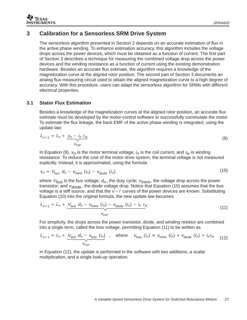
3.1 Stator Flux Estimation
Besides a knowledge of the magnetization curves at the aligned rotor position, an accurate fluxestimate must be developed by the motor-control software to successfully commutate the motor.To estimate the flux linkage, the back EMF of the active phase winding is integrated, using theupdate law:
�n�1� �n� vn� in rw
vEMF
In Equation (9), vn is the motor terminal voltage, in is the coil current, and rw is windingresistance. To reduce the cost of the motor drive system, the terminal voltage is not measuredexplicitly. Instead, it is approximated, using the formula
vn� Vbus dn� vtrans (in)� vdiode (in)
where Vbus is the bus voltage; dn , the duty cycle; vtrans, the voltage drop across the powertransistor; and vdiode, the diode voltage drop. Notice that Equation (10) assumes that the busvoltage is a stiff source, and that the v – i curves of the power devices are known. SubstitutingEquation (10) into the original formula, the new update law becomes
�n�1� �n� Vbus dn� vtrans (in)� vdiode (in)� in rw
vEMF
For simplicity, the drops across the power transistor, diode, and winding resistor are combinedinto a single term, called the loss voltage, permitting Equation (11) to be written as
�n�1� �n� Vbus dn� vloss (in) , where vloss (in)� vtrans (in)� vdiode (in)� inrw
vEMF
In Equation (12), the update is performed in the software with two additions, a scalarmultiplication, and a single look-up operation.
(9)
(10)
(11)
(12)
SPRA600
28 A Variable-Speed Sensorless Drive System for Switched Reluctance Motors
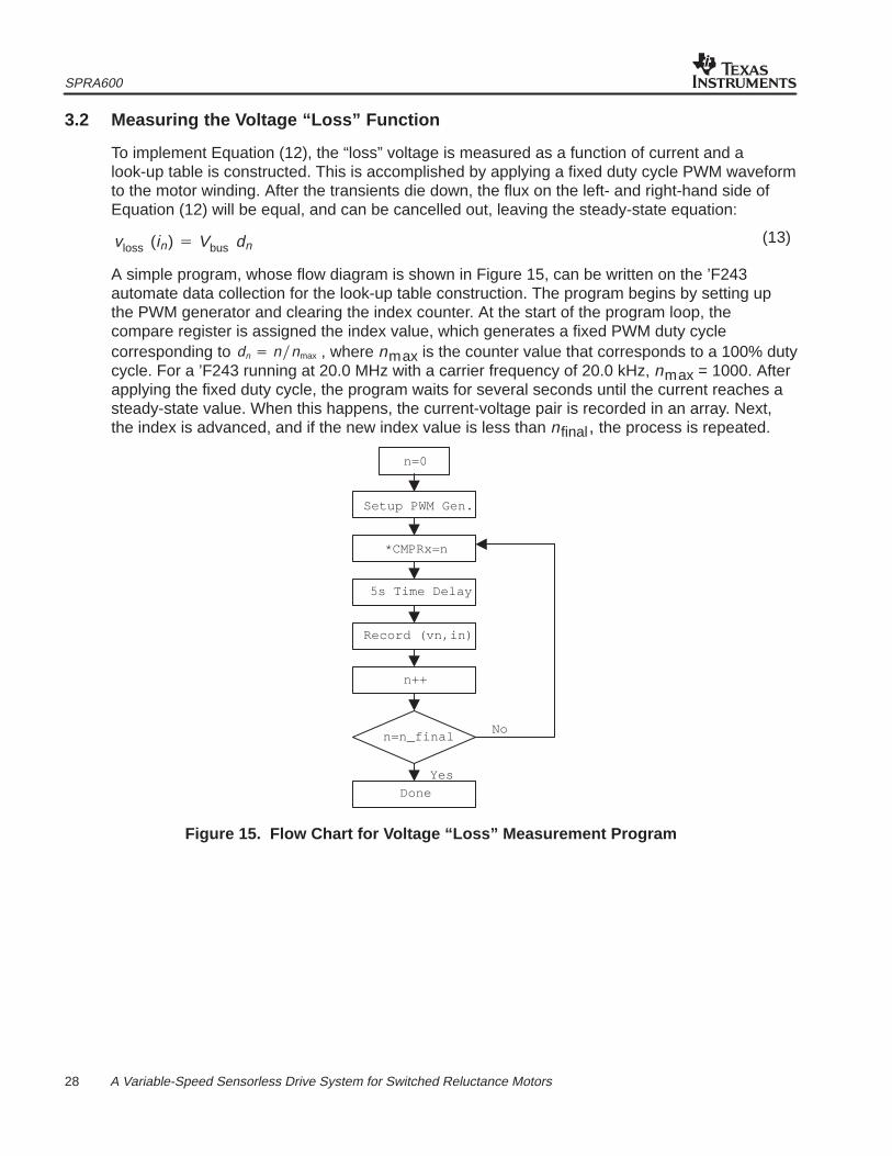
3.2 Measuring the Voltage “Loss” Function
To implement Equation (12), the “loss” voltage is measured as a function of current and alook-up table is constructed. This is accomplished by applying a fixed duty cycle PWM waveformto the motor winding. After the transients die down, the flux on the left- and right-hand side ofEquation (12) will be equal, and can be cancelled out, leaving the steady-state equation:
vloss (in) � Vbus dn
A simple program, whose flow diagram is shown in Figure 15, can be written on the ’F243automate data collection for the look-up table construction. The program begins by setting upthe PWM generator and clearing the index counter. At the start of the program loop, thecompare register is assigned the index value, which generates a fixed PWM duty cyclecorresponding to dn � n�nmax , where nmax is the counter value that corresponds to a 100% dutycycle. For a ’F243 running at 20.0 MHz with a carrier frequency of 20.0 kHz, nmax = 1000. Afterapplying the fixed duty cycle, the program waits for several seconds until the current reaches asteady-state value. When this happens, the current-voltage pair is recorded in an array. Next,the index is advanced, and if the new index value is less than nfinal, the process is repeated.
Setup PWM Gen.
5s Time Delay
Record (vn,in)
Yes
No
Done
*CMPRx=n
n=0
n++
n=n_final
Figure 15. Flow Chart for Voltage “Loss” Measurement Program
(13)
SPRA600
29 A Variable-Speed Sensorless Drive System for Switched Reluctance Motors
To avoid blowing fuses that are located on the digital motor controller board or damagingcomponents, nfinal must be carefully chosen. To calculate an approximate value for nfinal ,calculate the “loss” voltage at the maximum current, using the formula:
vloss (imax) � vdiode (imax) � vtrans (imax) � imax rw
From this, calculate the duty cycle needed to generate this “loss” voltage:
nfinal � �vloss(imax)Vbus
� n max
Using an imax = 4.0 A, a diode drop of 0.70 V, and a voltage drop of 1.1 V across the IGBT, awinding resistance of 2.5 ohms, a typical bus voltage of 170.0 V, and an nmax = 1000, nfinal ≈ 70.
3.3 Generating a Voltage “Loss” Look-up Table
After the voltage-current data is recorded in the array, it is exported via the XDS510 to the PC,the data is fitted with a polynomial curve, with voltage as a function of current. To simplifycalculation of the table index, the function is evaluated at the current points
in � imax � n256� � n � 0��� 255
Using these points, an index into the 256-point look-up table can be rapidly calculated byright-shifting the 10-bit current measurement over two places.
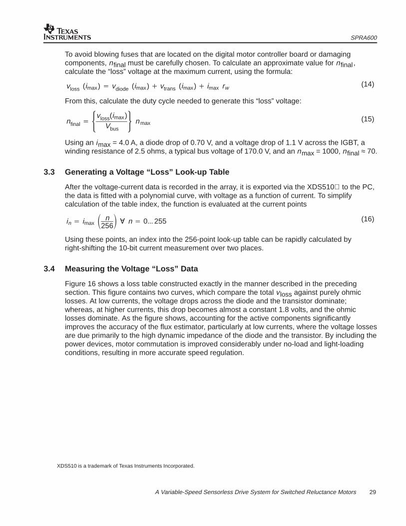
3.4 Measuring the Voltage “Loss” Data
Figure 16 shows a loss table constructed exactly in the manner described in the precedingsection. This figure contains two curves, which compare the total v loss against purely ohmiclosses. At low currents, the voltage drops across the diode and the transistor dominate;whereas, at higher currents, this drop becomes almost a constant 1.8 volts, and the ohmiclosses dominate. As the figure shows, accounting for the active components significantlyimproves the accuracy of the flux estimator, particularly at low currents, where the voltage lossesare due primarily to the high dynamic impedance of the diode and the transistor. By including thepower devices, motor commutation is improved considerably under no-load and light-loadingconditions, resulting in more accurate speed regulation.
XDS510 is a trademark of Texas Instruments Incorporated.
(14)
(15)
(16)
SPRA600
30 A Variable-Speed Sensorless Drive System for Switched Reluctance Motors
Current (A)
Vol
tage
(V
)
12
10
8
6
4
2
00 0.5 1 2 3 41.5 2.5 3.5
total vlossohmic losses
Figure 16. Voltage “Loss” vs. Current for the Emerson Electric SRM and the Spectrum DigitalMotor Control Board
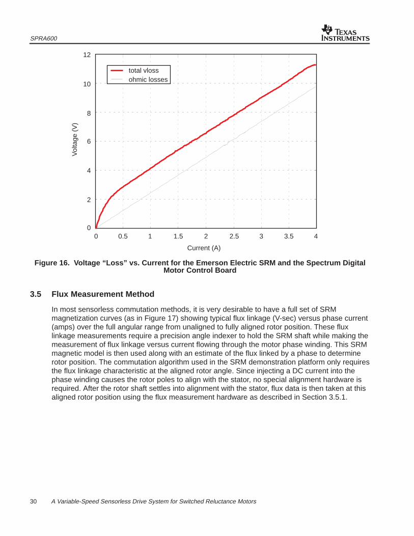
3.5 Flux Measurement Method
In most sensorless commutation methods, it is very desirable to have a full set of SRMmagnetization curves (as in Figure 17) showing typical flux linkage (V-sec) versus phase current(amps) over the full angular range from unaligned to fully aligned rotor position. These fluxlinkage measurements require a precision angle indexer to hold the SRM shaft while making themeasurement of flux linkage versus current flowing through the motor phase winding. This SRMmagnetic model is then used along with an estimate of the flux linked by a phase to determinerotor position. The commutation algorithm used in the SRM demonstration platform only requiresthe flux linkage characteristic at the aligned rotor angle. Since injecting a DC current into thephase winding causes the rotor poles to align with the stator, no special alignment hardware isrequired. After the rotor shaft settles into alignment with the stator, flux data is then taken at thisaligned rotor position using the flux measurement hardware as described in Section 3.5.1.
SPRA600
31 A Variable-Speed Sensorless Drive System for Switched Reluctance Motors
Current (A)
Flu
x Li
nkag
e (V
-s)
UnalignedAngle
Aligned Angle
Figure 17. SRM Magnetization Curves
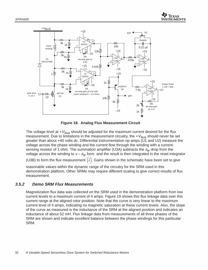
3.5.1 Flux Measurement Hardware
Figure 18 shows the schematic of the analog flux measurement hardware used to collectmagnetic data for the SRM used in the demonstration platform. In the SRM, flux linkage in each
phase of the motor can be calculated from the basic equation �^�� (V � iR) dt , relating flux
linkage ��^� to voltage across the phase winding and current flow through the winding. Referring
to the schematic, the semiconductor switch (Q1) controls the current through the SRM phasewinding and is driven by a pulse generator at the gate drive input with a pulse width that isadjusted to allow the current to reach a steady-state level. For the SRM used in thisdemonstration platform with an electrical time constant of 20 msec, the pulse width of the gatedrive should be set to approximately 100 msec.
SPRA600
32 A Variable-Speed Sensorless Drive System for Switched Reluctance Motors
+
_
+
_
+
_
+
_
+
_
+VBUS
D1HFA15TB60
motorwinding
3k
1
3k
3k
3k
22
gate drive0–15 V
IRF740Q1
1k
1k
1k
1k
10kset amp gain at
4.00
+15
U1AD524
–1510k
5.62k
U2AD524
10kset amp gain at 5.62 with
motor winding R = 2.5 ohms
–15
10k
+15
–15
U3ATL087
+15
–15
5k10k
1k2N2907A
Q2
gate
gate Q3
2N4858
0.22 µF+15
–15
470kU3B
TL087
7.5kU3C
TL087
+15
–15
36kset amp gain
at 4.14
2k
1k
Output Scale1 volt = 40ψ
1
2
1
2
3
3
8
13
8
13
1010
10
9
9
7
7
2
3
7
4
62
34
76
3
24
76
+15
Figure 18. Analog Flux Measurement Circuit
The voltage level at +Vbus should be adjusted for the maximum current desired for the fluxmeasurement. Due to limitations in the measurement circuitry, the +Vbus should never be setgreater than about +40 volts dc. Differential instrumentation op amps (U1 and U2) measure thevoltage across the phase winding and the current flow through the winding with a current-sensing resistor of 1 ohm. The summation amplifier (U3A) subtracts the irw drop from thevoltage across the winding to v – irw form and the result is then integrated in the reset integrator
(U3B) to form the flux measurement ��^�. Gains shown in the schematic have been set to give
reasonable values within the dynamic range of the circuitry for the SRM used in thisdemonstration platform. Other SRMs may require different scaling to give correct results of fluxmeasurement.
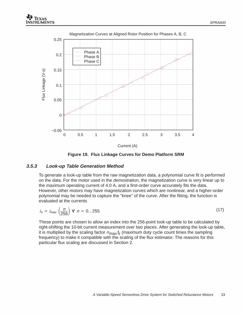
3.5.2 Demo SRM Flux Measurements
Magnetization flux data was collected on the SRM used in the demonstration platform from lowcurrent levels to a maximum current of 4 amps. Figure 19 shows this flux linkage data over thiscurrent range at the aligned rotor position. Note that the curve is very linear to the maximumcurrent level of 4 amps, indicating no magnetic saturation at these current levels. Also, the slopeof the curve as measured is the inductance of the SRM at the aligned position and indicates aninductance of about 52 mH. Flux linkage data from measurements of all three phases of theSRM are shown and indicate excellent balance between the phase windings for this particularSRM.
SPRA600
33 A Variable-Speed Sensorless Drive System for Switched Reluctance Motors
Current (A)
Flu
x Li
nkag
e (V
-s)
Magnetization Curves at Aligned Rotor Position for Phases A, B, C
Phase APhase BPhase C
–0.05
0
0.05
0.1
0.15
0.2
0.25
0.50 1.5 2.5 3.51 2 3 4
Figure 19. Flux Linkage Curves for Demo Platform SRM
3.5.3 Look-up Table Generation Method
To generate a look-up table from the raw magnetization data, a polynomial curve fit is performedon the data. For the motor used in the demostration, the magnetization curve is very linear up tothe maximum operating current of 4.0 A, and a first-order curve accurately fits the data.However, other motors may have magnetization curves which are nonlinear, and a higher-orderpolynomial may be needed to capture the “knee” of the curve. After the fitting, the function isevaluated at the currents
in � imax � n256� � n � 0��� 255
These points are chosen to allow an index into the 256-point look-up table to be calculated byright-shifting the 10-bit current measurement over two places. After generating the look-up table,it is multiplied by the scaling factor nmaxfs (maximum duty cycle count times the samplingfrequency) to make it compatible with the scaling of the flux estimator. The reasons for thisparticular flux scaling are discussed in Section 2.
(17)
SPRA600
34 A Variable-Speed Sensorless Drive System for Switched Reluctance Motors
References1. Lyons, J., S. MacMinn, and M. Preston. “Flux/Current Methods for SRM Rotor Position
Estimation.” IEEE IAS Meeting Conf. Record, 1991.
IMPORTANT NOTICE
Texas Instruments and its subsidiaries (TI) reserve the right to make changes to their products or to discontinueany product or service without notice, and advise customers to obtain the latest version of relevant informationto verify, before placing orders, that information being relied on is current and complete. All products are soldsubject to the terms and conditions of sale supplied at the time of order acknowledgement, including thosepertaining to warranty, patent infringement, and limitation of liability.
TI warrants performance of its semiconductor products to the specifications applicable at the time of sale inaccordance with TI’s standard warranty. Testing and other quality control techniques are utilized to the extentTI deems necessary to support this warranty. Specific testing of all parameters of each device is not necessarilyperformed, except those mandated by government requirements.
CERTAIN APPLICATIONS USING SEMICONDUCTOR PRODUCTS MAY INVOLVE POTENTIAL RISKS OFDEATH, PERSONAL INJURY, OR SEVERE PROPERTY OR ENVIRONMENTAL DAMAGE (“CRITICALAPPLICATIONS”). TI SEMICONDUCTOR PRODUCTS ARE NOT DESIGNED, AUTHORIZED, ORWARRANTED TO BE SUITABLE FOR USE IN LIFE-SUPPORT DEVICES OR SYSTEMS OR OTHERCRITICAL APPLICATIONS. INCLUSION OF TI PRODUCTS IN SUCH APPLICATIONS IS UNDERSTOOD TOBE FULLY AT THE CUSTOMER’S RISK.
In order to minimize risks associated with the customer’s applications, adequate design and operatingsafeguards must be provided by the customer to minimize inherent or procedural hazards.
TI assumes no liability for applications assistance or customer product design. TI does not warrant or representthat any license, either express or implied, is granted under any patent right, copyright, mask work right, or otherintellectual property right of TI covering or relating to any combination, machine, or process in which suchsemiconductor products or services might be or are used. TI’s publication of information regarding any thirdparty’s products or services does not constitute TI’s approval, warranty or endorsement thereof.
Copyright 1999, Texas Instruments Incorporated