Embed Size (px)
Citation preview
Nuclear Engineering and Design 183 (1998) 117–132
A verification and validation method and its application todigital safety systems in ABWR nuclear power plants
Akira Fukumoto a,*, Toshifumi Hayashi a, Hiroshi Nishikawa b, Hiroshi Sakamoto c,Teruaki Tomizawa d, Tadayuki Yokomura e
a Computer Control System Technology Group, Power and Industrial Systems Research and De6elopment Center, 1 Toshiba-cho,Fuchu-shi, Tokyo 183, Japan
b 1st Nuclear Power Generation Control System Designing Group, Power Generation Control System De6elopment Department,Fuchu Works, Toshiba Corporation, 1 Toshiba-cho, Fuchu-shi, Tokyo 183, Japan
c Nuclear Control and Electrical Engineering Department, Nuclear Energy Di6ision, Toshiba Corporation, 8 Shinsugita-cho,Isogo-ku, Yokohama 235, Japan
d Technology Planning Department, Nuclear Energy Di6ision, Toshiba Corporation, 1–3, Uchisaiwai-cho, 1-ohome, Chiyoda-ku,Tokyo 100, Japan
e Electrical and Mechanical Engineering, Nuclear Power Engineering Department, Tokyo Electric Power Company,1-3 Uchisaiwai-cho, 1-chome, Chiyoda-ku, Tokyo 100, Japan
Received 31 July 1997; received in revised form 2 February 1998; accepted 25 March 1998
Abstract
A verification and validation (V&V) method has been developed and applied to newly developed digital safetysystems for the first ABWR plant, Kashiwazaki–Kariwa unit No. 6 of the Tokyo Electric Power Company. Thispaper describes the method and experience gained from its application. The method was developed on the basis ofdomestic and foreign standards and guidelines, and covers the more concrete procedures required for actual V&V.The application of problem oriented language (POL) helps make the V&V feasible and reliable. A personal-computer-based automatic test tool for the validation test has been developed and utilized. This tool is used to carry out thepre-defined validation test procedure automatically and produce a test report, and it was found to be effective inreducing the time and manpower required for the validation test. The validation test covers dynamic transient testsin which the response of the digital safety system against the simulated design based transients are tested. The toolenables automatic execution of the dynamic test. © 1998 Published by Elsevier Science S.A. All rights reserved.
1. Introduction
Recently, applications of digital systems tosafety systems of nuclear power plants have been
studied, and a number of systems have been in-stalled in both new and existing plants as up-grades. Canadian CANDU plants havecomputerized shutdown systems (Ichiyen andJoannou, 1995). French N4 PWR plants havemicroprocessor based reactor protections systems(Burel, 1995). Microprocessor based safety sys-
* Corresponding author. Tel.: +81 3 423332564; Fax: +813 423408060; e-mail: [email protected]
0029-5493/98/$19.00 © 1998 Published by Elsevier Science S.A. All rights reserved.
PII S0029-5493(98)00186-1
A. Fukumoto et al. / Nuclear Engineering and Design 183 (1998) 117–132118
tems have also been installed in a newly con-structed PWR plant in the United Kingdom(Daily and Orme, 1992). As upgrades, analogsafety systems in several exiting PWR plants inthe United States have been replaced by digitalsystems, and digital safety systems have beenadopted as replacements for Soviet designed I&Csystems in a Russian made plant in the Czechrepublic (Waclo, 1994). Digital systems have thefollowing advantages over analog systems.1. Fewer characteristics change due to aging.2. Easier configurability as a redundant system.3. Easier modification and addition of new fea-
tures by changing the system software.4. Easier use of optic fiber data transmission
which improves immunity against externalelectro-magnetic and radio-frequency noise.
5. Improved maintainability by introducing self-diagnosis, self-calibration, event and datarecording, and so on.
However, they also have the followingdisadvantages.1. Because signal processing is done by software,
it is difficult to observe the system status di-rectly, as it is possible in analog systems bywatching the relay operations.
2. Signal processing is performed sequentially, sothat processing time and timing constraintsmust be considered.
3. Signal processing is performed by micropro-cessors. Microprocessor halt due to softwareor hardware failure leads to the loss of signalprocessing capability.
4. Signal processing is based on digitized (i.e.discrete) data, so that the effects of digitiza-tion, such as accuracy, aliasing and so on mustbe considered
5. Detection of failures in software design anddevelopment may be more difficult andcomplex.
These disadvantages seem to be the backgroundfactors leading to discussions on the reliability ofsoftware based safety systems. It is generally dis-cussed that deliberate and elaborate efforts arerequired to cope with design errors which mayresult in a common mode failure. The reliabilityof software based safety system is a significantissue. Guidelines or standards such as IEEE7-
4.3.2 (1993), IEC880 (1986), JEAG4609 (1989)have been published for applying software baseddigital safety systems to nuclear power plants.These documents address the issues on reliabilityof software based safety systems and define re-quirements for hardware/software design, manu-facturing, verification and validation (V&V)procedures, documentation, maintenance and soon.
In Kashiwazaki-Kariwa unit No.6 (K-6) of theTokyo Electric Power Company, the first ABWRplant, a digital safety system has been imple-mented (Nishikawa and Sakamoto, 1994). Thispaper focuses on V&V aspects of the digital safetysystem in K-6. The basic requirements for V&Vset forth in the standards are summarized asfollows.1. Verification and Validation (V&V) procedures
should be performed and the results should bewell documented in an auditable manner.
2. V&V should be performed by a team or per-sonnel independent from the design and manu-facturing team.
3. V&V should cover all steps in system designand manufacturing from design to final test.
4. A V&V plan should be prepared and the V&Vshould be carried out on that basis.
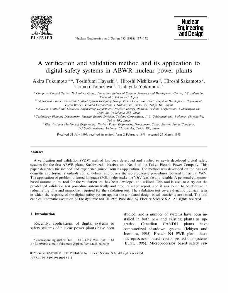
Fig. 1 shows basic flow of V&V procedures.Verification should be carried out at each step insystem design and manufacturing. At each verifi-cation step, it should be verified that the results ofthat step meet the requirements. The developedV&V method is based on the basic flow shown inFig. 1, but it has unique features such as itsintroduction of graphical problem oriented lan-guage (POL) and an automatic validation testtool.
POL is a kind of software language but doesnot require software coding which is generallyrequired when using software languages like C,PL/M, ADA, etc. POL directly interprets or com-piles graphically represented logic charts thatdefine the required logic calculation, and executesit. This feature enables visual software design,programming and verification, and makes theseprocesses transparent as for analog systems inwhich logic charts and relay circuit diagrams areused for design and verification. Both IEC880
A. Fukumoto et al. / Nuclear Engineering and Design 183 (1998) 117–132 119
Fig. 1. Basic flow of V&V.
(1986), IEEE7-4.3.2 (1993) address the method-ologies for reducing design errors and commonmode failures, and refer to system diversity as apossible approach if necessary. Regarding thisissue, independent hardwired circuits are installedin the digital safety system in K-6 based on theanalysis of anticipated transients without scram(ATWS). These circuits cover manual scram,manual activation of emergency core cooling sys-tems, manual closure of major containment isola-tion valves and hard-wired indication of safetyrelated parameters. In combination with theadoption of these circuits, POL was selected as asoftware language based on its visual program-
ming capability and experience gained throughmany applications to fossil power plants. It wasexpected that POL could make design and verifi-cation process similar to those for analog systemsand simplify detection of design errors whichmight lead to common mode failures in the designand verification stage.
The automatic test tool provides various combi-nations of test signals simulating sensor signals tothe safety system, and monitors the output signalsfrom the safety system. It judges whether thesafety system responds correctly to the providedtest signals, based on the criteria stored in thetool. The automatic test tool was used in the
A. Fukumoto et al. / Nuclear Engineering and Design 183 (1998) 117–132120
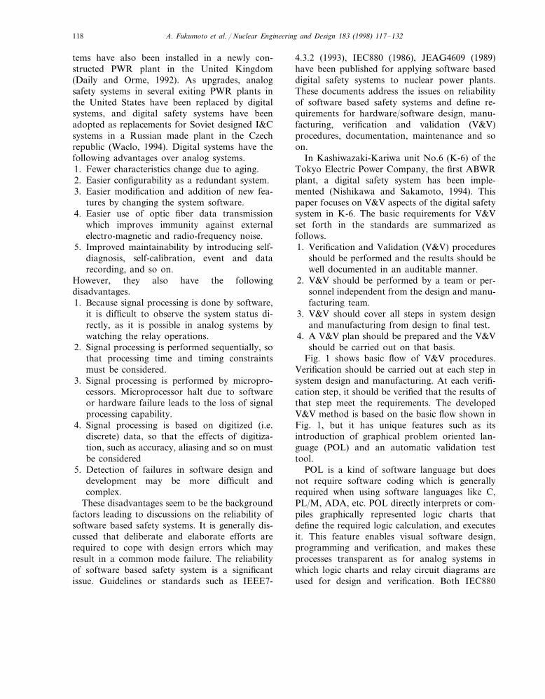
Fig. 2. Primary system configuration of the digital safety system.
validation test to detect undiscovered errors at theverification stage and to validate the overall sys-tem integrity.
This paper describes the outline of the newlydeveloped digital safety system, the detailed pro-cedures of the developed V&V method includingthe utilization of POL language and the auto-matic validation test tool, and the evaluation andexperience of its application.
2. Outline of the digital safety system
The newly developed digital safety system forABWR consists of a reactor protection system(RPS) and an engineered safety feature (ESF).Fig. 2 shows its primary configuration. The RPScontrols the scram function if abnormal eventsoccur. The ESF controls the activation of emer-gency core cooling systems, containment isolationand cooling system and so on.
2.1. Reactor protection system (RPS)
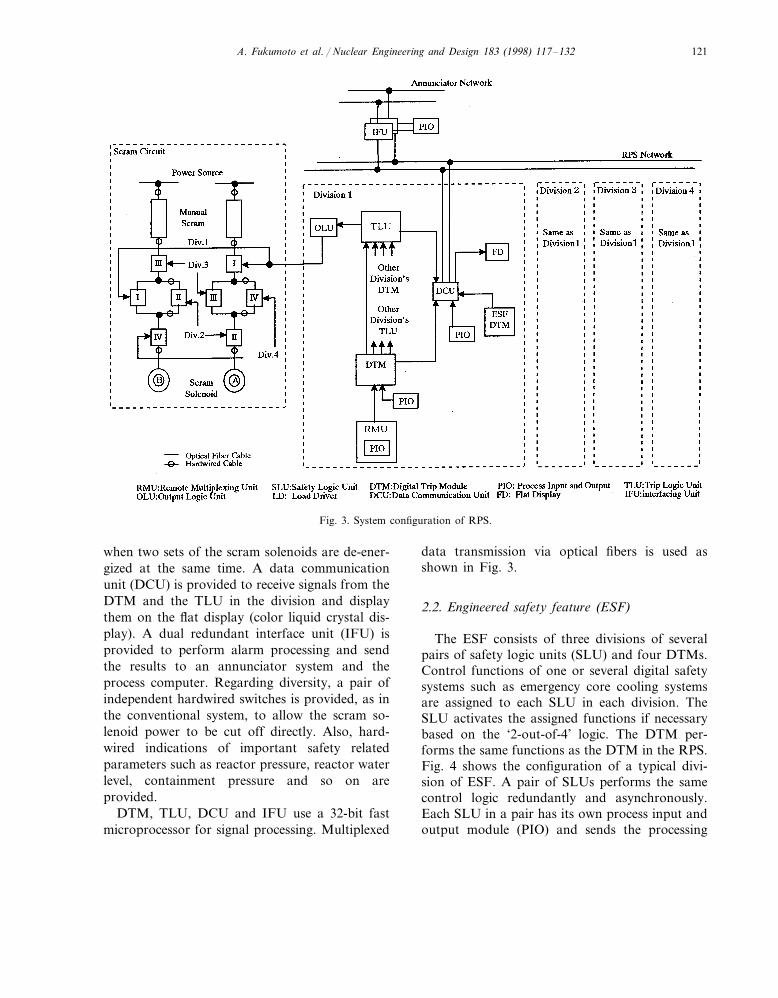
Fig. 3 shows the system configuration of theRPS. The RPS has four independent divisions,each provided with sensors for measuring processparameters. Signals from sensors are supplied tomultiplexing units at local panels where they aredigitized and sent to a digital trip module (DTM).The DTM compares the input signals with pre-defined setpoints and sends the results to a triplogic unit (TLU) as logic (1/0) signals. Each TLUin each division receives the results of the DTMsof the four divisions and performs ‘2-out-of-4’logic to validate the activation of the plant protec-tion function (if two or more DTMs detect theviolation of the setpoint, scram is validated by theTLU.). The outputs from the TLU are sent to ahard-wired scram circuit via an output logic unit(OLU). The hard-wired scram circuit consists oftwo sets of scram solenoids to form ‘2-out-of-4’logic circuits so that the reactor scram occurs only
A. Fukumoto et al. / Nuclear Engineering and Design 183 (1998) 117–132 121
Fig. 3. System configuration of RPS.
when two sets of the scram solenoids are de-ener-gized at the same time. A data communicationunit (DCU) is provided to receive signals from theDTM and the TLU in the division and displaythem on the flat display (color liquid crystal dis-play). A dual redundant interface unit (IFU) isprovided to perform alarm processing and sendthe results to an annunciator system and theprocess computer. Regarding diversity, a pair ofindependent hardwired switches is provided, as inthe conventional system, to allow the scram so-lenoid power to be cut off directly. Also, hard-wired indications of important safety relatedparameters such as reactor pressure, reactor waterlevel, containment pressure and so on areprovided.
DTM, TLU, DCU and IFU use a 32-bit fastmicroprocessor for signal processing. Multiplexed
data transmission via optical fibers is used asshown in Fig. 3.
2.2. Engineered safety feature (ESF)
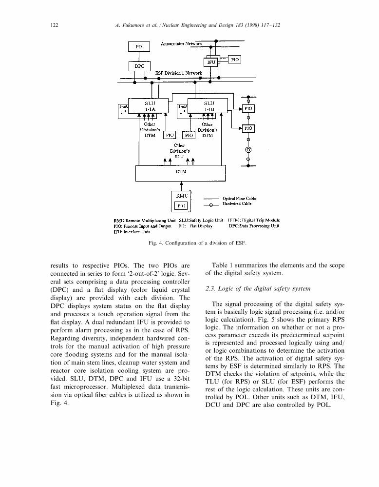
The ESF consists of three divisions of severalpairs of safety logic units (SLU) and four DTMs.Control functions of one or several digital safetysystems such as emergency core cooling systemsare assigned to each SLU in each division. TheSLU activates the assigned functions if necessarybased on the ‘2-out-of-4’ logic. The DTM per-forms the same functions as the DTM in the RPS.Fig. 4 shows the configuration of a typical divi-sion of ESF. A pair of SLUs performs the samecontrol logic redundantly and asynchronously.Each SLU in a pair has its own process input andoutput module (PIO) and sends the processing
A. Fukumoto et al. / Nuclear Engineering and Design 183 (1998) 117–132122
Fig. 4. Configuration of a division of ESF.
results to respective PIOs. The two PIOs areconnected in series to form ‘2-out-of-2’ logic. Sev-eral sets comprising a data processing controller(DPC) and a flat display (color liquid crystaldisplay) are provided with each division. TheDPC displays system status on the flat displayand processes a touch operation signal from theflat display. A dual redundant IFU is provided toperform alarm processing as in the case of RPS.Regarding diversity, independent hardwired con-trols for the manual activation of high pressurecore flooding systems and for the manual isola-tion of main stem lines, cleanup water system andreactor core isolation cooling system are pro-vided. SLU, DTM, DPC and IFU use a 32-bitfast microprocessor. Multiplexed data transmis-sion via optical fiber cables is utilized as shown inFig. 4.
Table 1 summarizes the elements and the scopeof the digital safety system.
2.3. Logic of the digital safety system
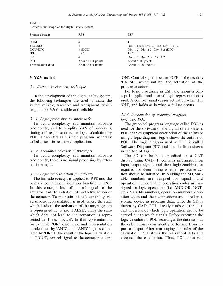
The signal processing of the digital safety sys-tem is basically logic signal processing (i.e. and/orlogic calculation). Fig. 5 shows the primary RPSlogic. The information on whether or not a pro-cess parameter exceeds its predetermined setpointis represented and processed logically using and/or logic combinations to determine the activationof the RPS. The activation of digital safety sys-tems by ESF is determined similarly to RPS. TheDTM checks the violation of setpoints, while theTLU (for RPS) or SLU (for ESF) performs therest of the logic calculation. These units are con-trolled by POL. Other units such as DTM, IFU,DCU and DPC are also controlled by POL.
A. Fukumoto et al. / Nuclear Engineering and Design 183 (1998) 117–132 123
Table 1Elements and scope of the digital safety system
ESFSystem element RPS
DTM 44TLU/SLU Div. 1 6×2, Div. 2 6×2, Div. 3 3×24
Div. 1 3, Div. 2 3, Div. 3 2 (DPC)4 (DCU)DCU/DPC1×2IFU 3×2
Div. 1 3, Div. 2 3, Div. 3 24FDAbout 1500 pointsPIO About 5000 points
Transmission data About 4500 points About 30 000 points
3. V&V method
3.1. System de6elopment technique
In the development of the digital safety system,the following techniques are used to make thesystem reliable, traceable and transparent, whichhelps make V&V feasible and reliable.
3.1.1. Logic processing by single taskTo avoid complexity and maintain software
traceability, and to simplify V&V of processingtiming and response time, the logic calculation byPOL is executed as a single program, generallycalled a task in real time application.
3.1.2. A6oidance of external interruptsTo avoid complexity and maintain software
traceability, there is no signal processing by exter-nal interrupts.
3.1.3. Logic representation for fail-safeThe fail-safe concept is applied to RPS and the
primary containment isolation function in ESF.In this concept, loss of control signal to theactuator leads to initiation of protective action ofthe actuator. To maintain fail-safe capability, re-verse logic representation is used, where the statewhich leads to the activation of the target systemis represented as ‘0’ i.e. ‘FALSE’, while the statewhich does not lead to the activation is repre-sented as ‘1’ i.e. ‘TRUE’. In this representation,for example, ‘OR’ logic in normal representationis calculated by ‘AND’, and ‘AND’ logic is calcu-lated by ‘OR’. If the result of the logic calculationis ‘TRUE’, control signal to the actuator is kept
‘ON’. Control signal is set to ‘OFF’ if the result is‘FALSE’, which initiates the activation of theprotective action.
For logic processing in ESF, the fail-as-is con-cept is applied and normal logic representation isused. A control signal causes activation when it is‘ON’, and holds as is when a failure occurs.
3.1.4. Introduction of graphical programlanguage: POL
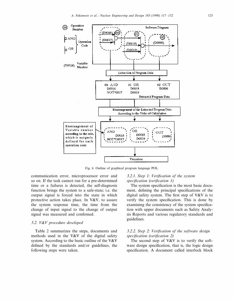
The graphical program language called POL isused for the software of the digital safety system.POL enables graphical description of the softwareusing a logic diagram. Fig. 6 shows the outline ofPOL. The logic diagram used in POL is calledSoftware Diagram (SD) and has the form shownin the top of Fig. 6.
The SD can be built or edited on a CRTdisplay using CAD. It contains information oninput/output signals and their logic combinationrequired for determining whether protective ac-tion should be initiated. In building the SD, vari-able numbers are assigned for signals, andoperation numbers and operation codes are as-signed for logic operations (i.e. AND OR, NOT,etc.). Variable numbers, operation numbers, oper-ation codes and their connections are stored in astorage device as program data. Once the SD isdrawn by CAD, POL directly reads out the dataand understands which logic operation should becarried out to which signals. Before executing thelogic calculation, POL rearranges the data so thatthe calculation is consistently performed from in-put to output. After rearranging the order of thecalculation, POL stores the rearranged data andexecutes the calculation. Thus, POL does not
A. Fukumoto et al. / Nuclear Engineering and Design 183 (1998) 117–132124
Fig. 5. Primary logic of RPS.
require logic program coding as when using pro-gram languages such as C, PL/M, etc. In POL,software coding means building a SD visuallyusing CAD. The CAD function for building andediting the SD can be installed together with POLto the digital safety systems or can be separatelyinstalled in a different computer system. Themaintenance tool hooked up to the digital safetysystem can be used for on-line display and editingof the SD. POL can display the running status ofthe software in the SD displayed on the terminalof the maintenance tool. POL enables visual pro-gramming and checking of the software, whichhelps maintain software traceability and transpar-
ency and makes the V&V feasible and reliable.This feature makes design and verification similarto those of analog systems in which logic chartsand relay circuit diagrams are used for design andverification. POL was selected based on this fea-ture and experience gained through many applica-tions to fossil power plants, in the belief that thepossibility of design errors and common modefailures can be reduced.
Logic calculation by POL is performed as asingle task. This task runs periodically for shorttime intervals. An independent self-diagnosisfunction is installed to monitor execution of thetask and to detect failures such as memory error,
A. Fukumoto et al. / Nuclear Engineering and Design 183 (1998) 117–132 125
Fig. 6. Outline of graphical program language POL.
3.2.1. Step 1: Verification of the systemspecification (6erification 1)
The system specification is the most basic docu-ment, defining the principal specifications of thedigital safety system. The first step of V&V is toverify the system specification. This is done byexamining the consistency of the system specifica-tion with upper documents such as Safety Analy-sis Reports and various regulatory standards andguidelines.
3.2.2. Step 2: Verification of the software designspecification (6erification 2)
The second step of V&V is to verify the soft-ware design specification, that is, the logic designspecification. A document called interlock block
communication error, microprocessor error andso on. If the task cannot run for a pre-determinedtime or a failures is detected, the self-diagnosisfunction brings the system to a safe-state; i.e. theoutput signal is forced into the state in whichprotective action takes place. In V&V, to assurethe system response time, the time from thechange of input signal to the change of outputsignal was measured and confirmed.
3.2. V&V procedure de6eloped
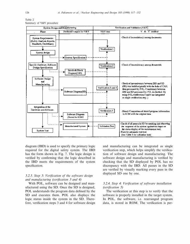
Table 2 summarizes the steps, documents andmethods used in the V&V of the digital safetysystem. According to the basic outline of the V&Vdefined by the standards and/or guidelines, thefollowing steps were taken.
A. Fukumoto et al. / Nuclear Engineering and Design 183 (1998) 117–132126
Table 2Summary of V&V procedure
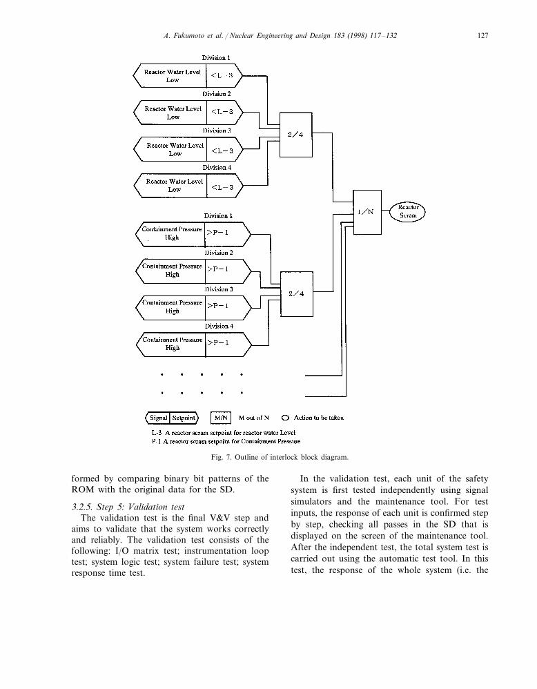
diagram (IBD) is used to specify the primary logicrequired for the digital safety system. The IBDhas the form shown in Fig. 7. The logic design isverified by confirming that the logic described inthe IBD meets the requirements of the systemspecification.
3.2.3. Step 3: Verification of the software designand manufacturing (6erification 3 and 4)
With POL, software can be designed and man-ufactured using the SD. Once the SD is designed,POL understands the program data defined by theSD and executes them. POL also displays thelogic status inside the system in the SD. There-fore, verification steps 3 and 4 for software design
and manufacturing can be integrated as singleverification step, which helps simplify the verifica-tion of software design and manufacturing. Thesoftware design and manufacturing is verified bychecking that the SD displayed by POL has nodiscrepancy with the IBD. All passes in the SDare verified by visually marking every pass in thedisplayed SD one by one.
3.2.4. Step 4: Verification of software installation(6erification 5)
The verification at this step is to verify that thesoftware is properly installed in the target system.In POL, the software, i.e. rearranged programdata, is stored in ROM. The verification is per-
A. Fukumoto et al. / Nuclear Engineering and Design 183 (1998) 117–132 127
Fig. 7. Outline of interlock block diagram.
formed by comparing binary bit patterns of theROM with the original data for the SD.
3.2.5. Step 5: Validation testThe validation test is the final V&V step and
aims to validate that the system works correctlyand reliably. The validation test consists of thefollowing: I/O matrix test; instrumentation looptest; system logic test; system failure test; systemresponse time test.
In the validation test, each unit of the safetysystem is first tested independently using signalsimulators and the maintenance tool. For testinputs, the response of each unit is confirmed stepby step, checking all passes in the SD that isdisplayed on the screen of the maintenance tool.After the independent test, the total system test iscarried out using the automatic test tool. In thistest, the response of the whole system (i.e. the
A. Fukumoto et al. / Nuclear Engineering and Design 183 (1998) 117–132128
Fig. 8. Configuration of automatic test tool.
status of initiation signal for protective action) isconfirmed against test input signals.
In Kashiwazaki–Kariwa Unit No. 6, the fol-lowing tests are included in the validation test bythe vendor (TOSHIBA) as additional tests: dy-namic transients test; random input test.
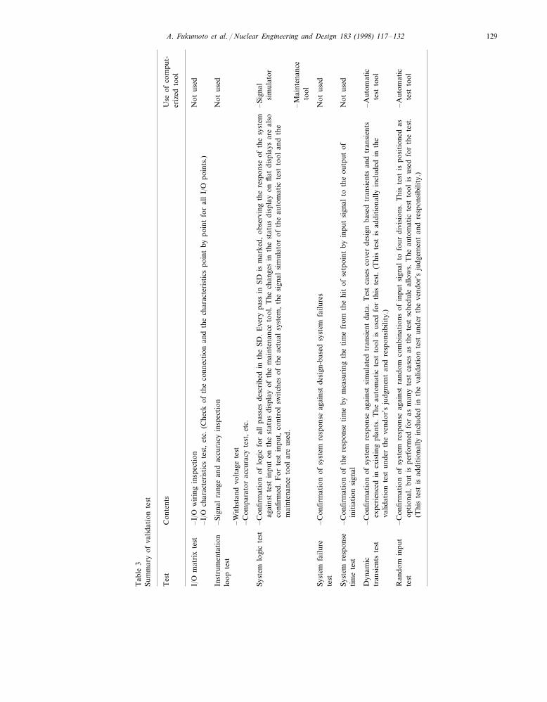
The contents of the above tests are summarizedin Table 3. The newly developed automatic testtool, which is described in the next subsection, isused for the system logic test, the dynamic tran-sient test and the random input test.
3.3. Automatic test tool
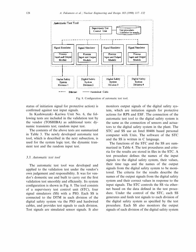
The automatic test tool was developed andapplied to the validation test under the vendor’sown judgement and responsibility. It was for ven-dor’s domestic use and built to carry out the firstvalidation test smoothly and efficiently. Its systemconfiguration is shown in Fig. 8. The tool consistsof a supervisory test control unit (STC), foursignal simulators (SS) with a PIO. Each SS isconnected to the DTM in each division of thedigital safety system via the PIO and hardwiredcables, and provides test signals to each division.Test signals are simulated sensor signals. It also
monitors output signals of the digital safety sys-tem, which are initiation signals for protectiveactions for RPS and ESF. The connection of theautomatic test tool to the digital safety system isthe same as the connection of sensors and actua-tors to the digital safety system in the plant. TheSTC and SS use an Intel 80486 based personalcomputer with Unix. The software of the STCand the SS is written in C language.
The functions of the STC and the SS are sum-marized in Table 4. The test procedures and crite-ria for the results are stored in files in the STC. Atest procedure defines the names of the inputsignals to the digital safety system, their values,their time tags and the names of the outputsignals from the digital safety system to be moni-tored. The criteria for the results describe thenames of the output signals from the digital safetysystem and their correct values in response to theinput signals. The STC controls the SS via ether-net based on the data defined in the test proce-dure. Under the control of the STC, each SSgenerates and feeds test signals to each division ofthe digital safety system as specified by the testprocedure. Each SS also monitors the outputsignals of each division of the digital safety system
A. Fukumoto et al. / Nuclear Engineering and Design 183 (1998) 117–132 129
Tab
le3
Sum
mar
yof
valid
atio
nte
st
Tes
tU
seof
com
put-
Con
tent
ser
ized
tool
I/O
mat
rix
test
Not
used
–I/
Ow
irin
gin
spec
tion
–I/
Och
arac
teri
stic
ste
st,
etc.
(Che
ckof
the
conn
ecti
onan
dth
ech
arac
teri
stic
spo
int
bypo
int
for
all
I/O
poin
ts.)
–Si
gnal
rang
ean
dac
cura
cyin
spec
tion
Inst
rum
enta
tion
Not
used
loop
test
–W
iths
tand
volt
age
test
–C
ompa
rato
rac
cura
cyte
st,
etc.
–Si
gnal
–C
onfir
mat
ion
oflo
gic
for
all
pass
esde
scri
bed
inth
eSD
.E
very
pass
inSD
ism
arke
d,ob
serv
ing
the
resp
onse
ofth
esy
stem
Syst
emlo
gic
test
sim
ulat
orag
ains
tte
stin
put
onth
est
atus
disp
lay
ofth
em
aint
enan
ceto
ol.
The
chan
ges
inth
est
atus
disp
lay
onfla
tdi
spla
ysar
eal
soco
nfirm
ed.
For
test
inpu
t,co
ntro
lsw
itch
esof
the
actu
alsy
stem
,th
esi
gnal
sim
ulat
orof
the
auto
mat
icte
stto
olan
dth
em
aint
enan
ceto
olar
eus
ed.
–M
aint
enan
ceto
ol
Syst
emfa
ilure
Not
used
–C
onfir
mat
ion
ofsy
stem
resp
onse
agai
nst
desi
gn-b
ased
syst
emfa
ilure
ste
st
Not
used
Syst
emre
spon
se–
Con
firm
atio
nof
the
resp
onse
tim
eby
mea
suri
ngth
eti
me
from
the
hit
ofse
tpoi
ntby
inpu
tsi
gnal
toth
eou
tput
ofti
me
test
init
iati
onsi
gnal
Dyn
amic
–A
utom
atic
–C
onfir
mat
ion
ofsy
stem
resp
onse
agai
nst
sim
ulat
edtr
ansi
ent
data
.T
est
case
sco
ver
desi
gnba
sed
tran
sien
tsan
dtr
ansi
ents
tran
sien
tste
stte
stto
olex
peri
ence
din
exis
ting
plan
ts.
The
auto
mat
icte
stto
olis
used
for
this
test
.(T
his
test
isad
diti
onal
lyin
clud
edin
the
valid
atio
nte
stun
der
the
vend
or’s
judg
men
tan
dre
spon
sibi
lity.
)
Ran
dom
inpu
t–
Aut
omat
ic–
Con
firm
atio
nof
syst
emre
spon
seag
ains
tra
ndom
com
bina
tion
sof
inpu
tsi
gnal
tofo
urdi
visi
ons.
Thi
ste
stis
posi
tion
edas
opti
onal
,bu
tis
perf
orm
edfo
ras
man
yte
stca
ses
asth
ete
stsc
hedu
leal
low
s.T
heau
tom
atic
test
tool
isus
edfo
rth
ete
st.
test
test
tool
(Thi
ste
stis
addi
tion
ally
incl
uded
inth
eva
lidat
ion
test
unde
rth
eve
ndor
’sju
dgem
ent
and
resp
onsi
bilit
y.)
A. Fukumoto et al. / Nuclear Engineering and Design 183 (1998) 117–132130
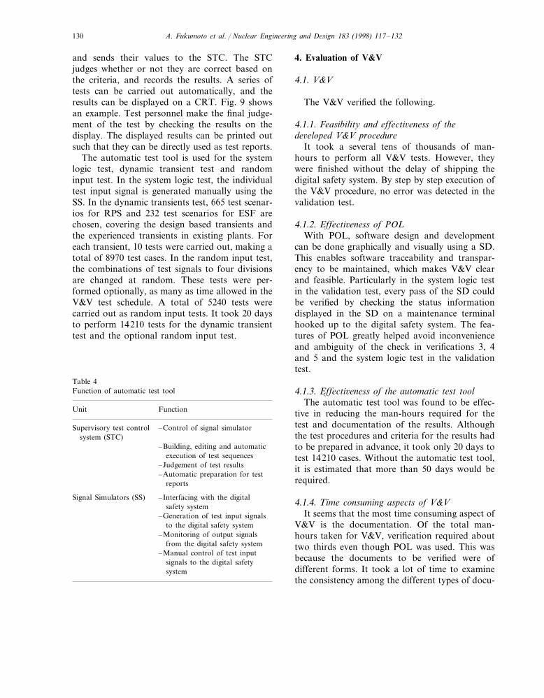
and sends their values to the STC. The STCjudges whether or not they are correct based onthe criteria, and records the results. A series oftests can be carried out automatically, and theresults can be displayed on a CRT. Fig. 9 showsan example. Test personnel make the final judge-ment of the test by checking the results on thedisplay. The displayed results can be printed outsuch that they can be directly used as test reports.
The automatic test tool is used for the systemlogic test, dynamic transient test and randominput test. In the system logic test, the individualtest input signal is generated manually using theSS. In the dynamic transients test, 665 test scenar-ios for RPS and 232 test scenarios for ESF arechosen, covering the design based transients andthe experienced transients in existing plants. Foreach transient, 10 tests were carried out, making atotal of 8970 test cases. In the random input test,the combinations of test signals to four divisionsare changed at random. These tests were per-formed optionally, as many as time allowed in theV&V test schedule. A total of 5240 tests werecarried out as random input tests. It took 20 daysto perform 14210 tests for the dynamic transienttest and the optional random input test.
4. Evaluation of V&V
4.1. V&V
The V&V verified the following.
4.1.1. Feasibility and effecti6eness of thede6eloped V&V procedure
It took a several tens of thousands of man-hours to perform all V&V tests. However, theywere finished without the delay of shipping thedigital safety system. By step by step execution ofthe V&V procedure, no error was detected in thevalidation test.
4.1.2. Effecti6eness of POLWith POL, software design and development
can be done graphically and visually using a SD.This enables software traceability and transpar-ency to be maintained, which makes V&V clearand feasible. Particularly in the system logic testin the validation test, every pass of the SD couldbe verified by checking the status informationdisplayed in the SD on a maintenance terminalhooked up to the digital safety system. The fea-tures of POL greatly helped avoid inconvenienceand ambiguity of the check in verifications 3, 4and 5 and the system logic test in the validationtest.
4.1.3. Effecti6eness of the automatic test toolThe automatic test tool was found to be effec-
tive in reducing the man-hours required for thetest and documentation of the results. Althoughthe test procedures and criteria for the results hadto be prepared in advance, it took only 20 days totest 14210 cases. Without the automatic test tool,it is estimated that more than 50 days would berequired.
4.1.4. Time consuming aspects of V&VIt seems that the most time consuming aspect of
V&V is the documentation. Of the total man-hours taken for V&V, verification required abouttwo thirds even though POL was used. This wasbecause the documents to be verified were ofdifferent forms. It took a lot of time to examinethe consistency among the different types of docu-
Table 4Function of automatic test tool
Unit Function
Supervisory test control –Control of signal simulatorsystem (STC)
–Building, editing and automaticexecution of test sequences
–Judgement of test results–Automatic preparation for test
reports
–Interfacing with the digitalSignal Simulators (SS)safety system
–Generation of test input signalsto the digital safety system
–Monitoring of output signalsfrom the digital safety system
–Manual control of test inputsignals to the digital safetysystem
A. Fukumoto et al. / Nuclear Engineering and Design 183 (1998) 117–132 131
Fig. 9. Example of automatic test tool output.
ments and to prepare reports in an auditablemanner. To reduce the time required for thedocumentation, streamlining, such as standardiza-tion of the documents and the introduction of amore helpful computer aided documentation tool,may be effective. In the validation test, the auto-matic test tool was helpful in reducing man-hoursowing to its automatic test report preparationfunction.
5. Conclusions
A V&V method has been developed and ap-plied to digital safety systems for ABWR nuclearpower plants. The utilization of the graphicalprogram language POL and the personal-com-puter-based automatic test tool are the uniquefeatures of this V&V method. POL helped main-tain software traceability and transparency in the
A. Fukumoto et al. / Nuclear Engineering and Design 183 (1998) 117–132132
verification, and it enabled all pass checks of thelogic combination in the system logic test. Theautomatic test tool can automatically execute testcases and prepare test reports. It was also used forthe dynamic transient test and the random inputtest. It was found that the automatic test toolhelped make these tests feasible in a short timeand improve the efficiency.
References
Burel, J.P., 1995. The use of digital technology for protectionand safety applications at French nuclear reactors. Kern-technik 60 (5/6), 220–224.
Daily, S., Orme, S., 1992. The reliability of the Sizewell ‘B’reactor protection system. International Conference onElectrical and Control Aspects of the Sizewell B PWR, pp.208–214.
Ichiyen, N.M., Joannou, P.K., 1995. Safety critical software
design approaches developed for Canadian nuclear powerplants. Kerntechnik 60 (5/6), 232–237.
International Electrotechnical Commission, 1986. IEC Stan-dard Publication 880, Software for Computers in theSafety Systems of Nuclear Power Stations.
Institute for Electrical and Electronics Engineers, 1993. IEEEStd 7-4.3.2-1993, IEEE Standard Criteria for Digital Com-puters in Safety Systems of Nuclear Power GeneratingStations.
Japan Electrical Society, 1989. JEAG4609, Guidelines forApplication of Digital Computer to Safety Protection Sys-tem.
Nishikawa, H., Sakamoto, H., 1994. Development of digitalsafety system logic and control. Proceedings of IAEATechnical Committee Meeting entitled ‘Advanced Controland Instrumentation Systems in Nuclear Power Plants:Design, Verification and Validation’, Helsinki, 20–23 June,1994.
Waclo, J., 1994. Design, verification and validation of digitalsafety systems for Temelin. Proceedings of IAEA TechnicalCommittee Meeting entitled ‘Advanced Control and In-strumentation Systems in Nuclear Power Plants: Design,Verification and Validation’, Helsinki, 20–23 June, 1994.
.


![Data Validation and Verification [Autosaved] · ON IP DATA VALIDATION, VERIFICATION AND EXCHANGE DATA VALIDATION AND VERIFICATION USING IPOBSD’S TOOLS. Data Quality Vicious Cycle](https://img.pdfslide.net/doc/110x75/5e9d0eaef4fa863d2d614a6c/data-validation-and-verification-autosaved-on-ip-data-validation-verification.jpg)