Embed Size (px)
Citation preview
Universal Journal of Petroleum Sciences 1 (2013), 39-67 www.papersciences.com
A View for Prospective EOR Projects in Iraqi Oil Fields
Salam Al Rbeawi Misan University
Misan - Iraq [email protected]
Abstract Exploitation of the enormous untapped energy source is the greatest challenge ever faced by the oil industry. Over the past four decades, the petroleum industry has been engaged in the research and development of various enhanced oil recovery (EOR) processes needed to produce the oil left behind (may reach more than 50% of OOIP) by conventional methods. Several techniques have been used all over the world for different types of formations. The main goal of the EOR process is to mobilize the "residual" oil throughout the entire reservoir. This is achieved by enhancing microscopic oil displacement and volumetric sweep efficiencies. There is no a single technique that can be considered a "cure all" for recovering additional oil from every reservoir. Each process has its specific application. Before initiating an EOR process, reservoir rock and fluid properties and past production history should be analyzed. It is also important to review the preceding secondary recovery process in order to determine the principal reasons why the residual oil was left in that reservoir. EOR techniques including process descriptions, production mechanisms, limitations, problems, and technical screening guides will be presented in this paper. It shows that gas injection process comes in the first rank of applications while thermal recovery process takes the second position. Chemical flooding is third EOR techniques that has been used for both sandstone and carbonate reservoirs. It shows also that more than 40% of gas injection processes have been used in carbonate reservoirs while 10% of thermal recovery techniques have been used in carbonate reservoirs. The current paper focuses on Iraqi oil fields that are previously or currently in stream. It shows a classification for these oil field based on zone, structure, surface area, reservoir, geological age, reservoir lithology, depth, net pay thickness, porosity, permeability, API gravity. This classification is used for the screening criteria for the prospective EOR projects in Iraq. The paper emphasize the fact that the great percentage of Iraqi oil fields is produced either naturally or by improved oil recovery, however, reasonable attentions have to be considered in the prospective future for serious need to use EOR techniques in several Iraqi oil fields to increase the ultimate recovery and extend reservoirs life. Key Word and Phrases Reservoir Engineering, Improved Oil & Gas Recovery, Secondary Oil & Gas Recovery, Enhanced Oil & Gas Recovery. 1. Introduction
Typically, the use of the natural stored reservoir energy may not produce more than 40% of the original oil in place by the primary mechanisms. As these energies are exhausted, programs of waterflooding or gas injection may then be applied to the reservoirs during the secondary recovery phase in order to maintain the energy of the reservoirs.
Fundamentally, waterflood involves pumping water through a well (injector) into the reservoir. The water is forced through the pore spaces to sweep the oil towards the producing wells (producers). The percentage of water in the produced fluids steadily increases until the cost of removing and disposing of water exceeds the income from oil production. After this point, it becomes uneconomical to continue the operation and the waterflooding is stopped. Some wells remain economically feasible at a watercut of up to 99%2. Other secondary recovery methods include CO2 flooding and hydrocarbon gas injection, which requires a nearby source of inexpensive gas in sufficient volume. As the secondary recovery techniques come to the point of uneconomical operation, the tertiary recovery or what has been called enhanced oil recovery (EOR) becomes the next strategy techniques for oil and gas reserve production.
39
S. Al Rbeawi
EOR implementation depends on the characteristics of the oil. For light oils, EOR refers to the techniques after primary and secondary recovery that include surfactant flood, polymer flood, miscible drive and even thermal methods. For heavy oils, EOR implies techniques after primary recovery which include steam injection and in-situ combustion. The application of enhanced oil recovery techniques allows the economic value of existing hydrocarbon resources fields to be maximized, through increasing oil recovery and field life extension. Identifying appropriate projects in any field can be a difficult task because of the large number of EOR techniques and reservoir combinations that need to be considered.
Since the production of oil by EOR process is rather difficult, risky, and need huge capital cost, the proper selection of the EOR method for a certain reservoir is important to attaining a successful and profitable project. The most difficult problem that faces reservoir engineers and experts is how to select the most appropriate method to enhance the oil production based on technical and economical factors. To achieve this mission, many reservoir factors must be studied carefully such as reservoir depth, reservoir area, reservoir temperature, porosity, permeability, oil gravity and oil viscosity, and also how these factors may affect each other.
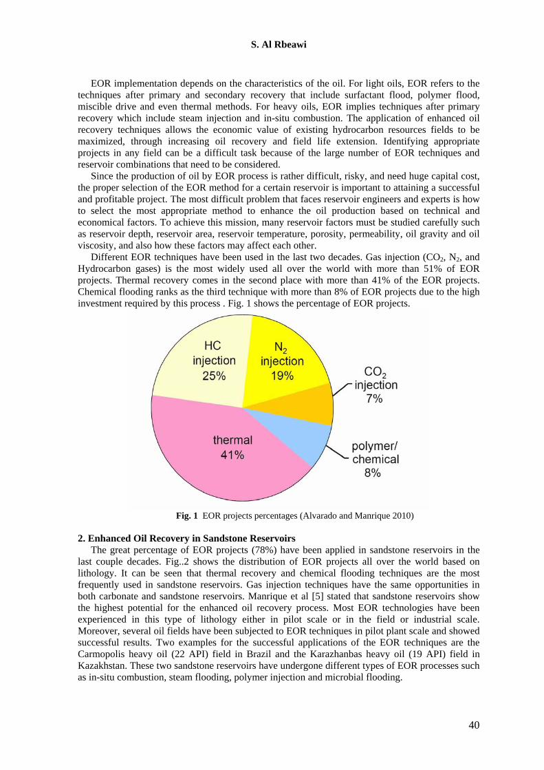
Different EOR techniques have been used in the last two decades. Gas injection (CO2, N2, and Hydrocarbon gases) is the most widely used all over the world with more than 51% of EOR projects. Thermal recovery comes in the second place with more than 41% of the EOR projects. Chemical flooding ranks as the third technique with more than 8% of EOR projects due to the high investment required by this process . Fig. 1 shows the percentage of EOR projects.
Fig. 1 EOR projects percentages (Alvarado and Manrique 2010)
2. Enhanced Oil Recovery in Sandstone Reservoirs
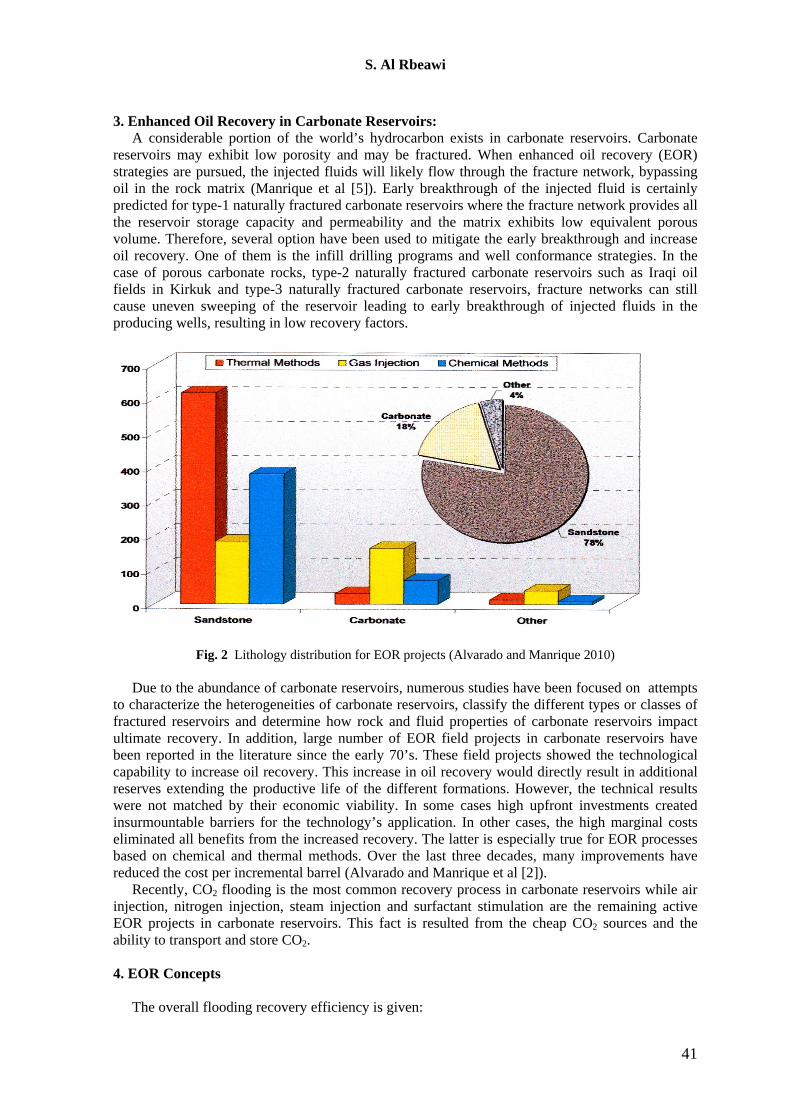
The great percentage of EOR projects (78%) have been applied in sandstone reservoirs in the last couple decades. Fig..2 shows the distribution of EOR projects all over the world based on lithology. It can be seen that thermal recovery and chemical flooding techniques are the most frequently used in sandstone reservoirs. Gas injection techniques have the same opportunities in both carbonate and sandstone reservoirs. Manrique et al [5] stated that sandstone reservoirs show the highest potential for the enhanced oil recovery process. Most EOR technologies have been experienced in this type of lithology either in pilot scale or in the field or industrial scale. Moreover, several oil fields have been subjected to EOR techniques in pilot plant scale and showed successful results. Two examples for the successful applications of the EOR techniques are the Carmopolis heavy oil (22 API) field in Brazil and the Karazhanbas heavy oil (19 API) field in Kazakhstan. These two sandstone reservoirs have undergone different types of EOR processes such as in-situ combustion, steam flooding, polymer injection and microbial flooding.
40
S. Al Rbeawi
3. Enhanced Oil Recovery in Carbonate Reservoirs: A considerable portion of the world’s hydrocarbon exists in carbonate reservoirs. Carbonate
reservoirs may exhibit low porosity and may be fractured. When enhanced oil recovery (EOR) strategies are pursued, the injected fluids will likely flow through the fracture network, bypassing oil in the rock matrix (Manrique et al [5]). Early breakthrough of the injected fluid is certainly predicted for type-1 naturally fractured carbonate reservoirs where the fracture network provides all the reservoir storage capacity and permeability and the matrix exhibits low equivalent porous volume. Therefore, several option have been used to mitigate the early breakthrough and increase oil recovery. One of them is the infill drilling programs and well conformance strategies. In the case of porous carbonate rocks, type-2 naturally fractured carbonate reservoirs such as Iraqi oil fields in Kirkuk and type-3 naturally fractured carbonate reservoirs, fracture networks can still cause uneven sweeping of the reservoir leading to early breakthrough of injected fluids in the producing wells, resulting in low recovery factors.
Fig. 2 Lithology distribution for EOR projects (Alvarado and Manrique 2010)
Due to the abundance of carbonate reservoirs, numerous studies have been focused on attempts to characterize the heterogeneities of carbonate reservoirs, classify the different types or classes of fractured reservoirs and determine how rock and fluid properties of carbonate reservoirs impact ultimate recovery. In addition, large number of EOR field projects in carbonate reservoirs have been reported in the literature since the early 70’s. These field projects showed the technological capability to increase oil recovery. This increase in oil recovery would directly result in additional reserves extending the productive life of the different formations. However, the technical results were not matched by their economic viability. In some cases high upfront investments created insurmountable barriers for the technology’s application. In other cases, the high marginal costs eliminated all benefits from the increased recovery. The latter is especially true for EOR processes based on chemical and thermal methods. Over the last three decades, many improvements have reduced the cost per incremental barrel (Alvarado and Manrique et al [2]).
Recently, CO2 flooding is the most common recovery process in carbonate reservoirs while air injection, nitrogen injection, steam injection and surfactant stimulation are the remaining active EOR projects in carbonate reservoirs. This fact is resulted from the cheap CO2 sources and the ability to transport and store CO2.
4. EOR Concepts
The overall flooding recovery efficiency is given:
41
S. Al Rbeawi
(1) where:
overall recovery efficiency, fraction or percent. displacement efficiency within the volume swept by injected fluid, fraction, or percent. volumetric swept efficiency, fraction or percent of the reservoir volume actually swept by
injected fluid. Displacement efficiency is influenced by rock and fluid properties and throughput (pore
volumes injected). It can be determined by: (1) Laboratory core floods:
Laboratory core floods, ideally using representative formation cores and actual reservoir fluids, are the preferred method for obtaining of and :
(2)
(2) Frontal advance theory, (assuming ):
Fractional flow theory can be used to estimate Sor and ED, but it requires measured water-oil relative permeability curves.
(3)
(3) Empirical correlations.
EV Volumetric swept efficiency is defined by:
(4) where: EA = areal swept efficiency-fraction of the pattern area or intended flood area that is swept by the
displacing fluid. EI = vertical or invasion swept efficiency-fraction of the pattern thickness or intended thickness that
is swept by the displacing fluid. There are basically three physical factors that lead to high residual oil saturation after primary
and secondary recovery: 1. High oil viscosity. 2. Interfacial forces. 3. Reservoir heterogeneity.
The goal of EOR processes is to mobilize the "residual" oil throughout the entire reservoir. This is achieved by enhancing microscopic oil displacement and volumetric swept efficiencies. Oil displacement efficiency is increased by decreasing oil viscosity (e.g., thermal floods) or by reducing capillary forces or interfacial tension (e.g., chemical floods). Volumetric swept efficiency is improved by decreasing the drive water mobility (e.g., polymer floods).
If mobility (permeability/viscosity) of the displacing phase is greater than the phase being displaced, the mobility ratio is unfavorable (i.e. M>1).
42
S. Al Rbeawi
(5)
M can be made smaller by lowering the viscosity of oil, increasing the viscosity of the displacing
phase, increasing the oil permeability, or decreasing the displacing phase permeability. Another parameter that plays a very important role in EOR is the “capillary number” which is a dimensionless group expressing the ratio of viscous to interfacial forces:
(6)
Abrams [1], included the effect of a water-wet core by modifying this group to:
(7)
As Nc is increased, the residual oil saturation decreases. An increase in Nc is obtained by in-
creasing pressure gradient, lowering oil viscosity, or decreasing interfacial tension. For miscible displacement, the interfacial tension approaches zero, and the oil displacement efficiency on the microscopic scale is very good. 5. EOR Techniques
There is no a single technique that can be considered a "cure all" for recovering additional oil from every reservoir. Each process has its specific application. Before initiating an EOR process, reservoir rock and fluid properties and past production history should be analyzed. It is also important to review the preceding secondary recovery process in order to determine the principal reasons why the residual oil was left in that reservoir. Factors that strongly affect the success of a waterflood will usually also affect the success of a subsequent tertiary project.
The following methods are discussed including process description, production mechanisms, limitations, problems, and technical screening guides:
5.1 Thermal Recovery
Many reservoirs contain highly viscous crude oil refers to us as "heavy oil reservoirs". Attempts to produce such oil by primary recovery or with waterflooding will yield very poor recoveries. Often this oil is too viscous to flow, or it requires pressures high enough to fracture the reservoir. Even if the oil is movable by waterflooding, the resultant fingering caused by the unfavorable viscosity ratio provides poor recovery. Application of heat is often the only feasible solution to such reservoirs. Thermal methods are primarily used for heavy viscous oil (10-20 API) and tar sands. About 60% of all EOR oil production was due to thermal recovery. Two types of thermal recovery are used to produce heavy oil formations: steam injection and in-situ combustion. Steam injection is a process where the heat is given to the formation using steam stream. This process has three different techniques: 1) Steam stimulation 2) Steam flooding, and 3) Steam assisted gravity drainage (SAGD). The three techniques have been used all over the world to recover heavy to extra heavy oil from sandstone reservoirs. Canada and Russia are the two places where thermal recovery is concentrated.
In-situ combustion (ISC) is the oldest thermal recovery method. It has been used since 1920’s with many successes and failures. Although several projects have been reported economically attractive, this recovery method is considered as a high-risk process. Air injection in heavy and light crude oil reservoirs is known as ISC but is also termed as high pressure air injection (HPAI)
43
S. Al Rbeawi
when is used in deep light crude oil reservoirs. Air injection has proven to be an effective recovery method in a variety of reservoir types and conditions and recently has received considerable attention for onshore and offshore applications based several successful projects in light crude oil reservoirs (Manrique et al [5]). 5.1.1 Steam Stimulation
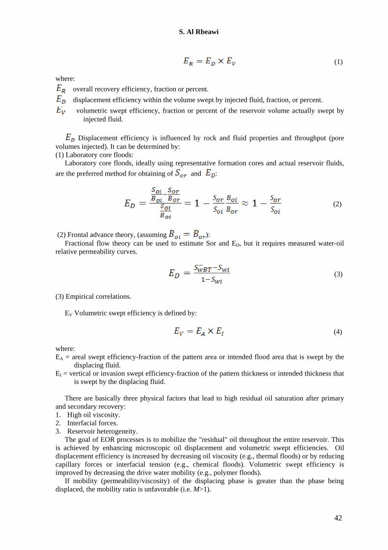
Steam stimulation, also known as "steam soak," "cyclic steam injection," or "huff-and-puff' is the most successful thermal recovery process. It involves a single well, until communication between wells develops. Steam is injected into the well at a high rate for a short period of time (a few weeks); next the steam is allowed to soak in for a few days, then the well is allowed to flow back and pumped. Fig. 3 shows the steam stimulation process.
Fig. 3 Steam stimulation process.
The oil rate increases initially, then drops off. When the rate becomes low, the entire process is repeated. This process is repeated many times until the well becomes uneconomic; or in some cases, it is converted from steam stimulation to steam flooding. In the stimulation process, the steam fingers through the oil around the well bore and heats the oil. The soak period permits the oil to be heated even further. During the production cycle, the mobilized oil flows into the wellbore, as a result of pressure drop, gravity, and other mechanisms. This process is most effective in highly viscous oils with a good reservoir permeability. The performance of this method drops as more and more cycles are carried out. Oil recovery is generally very small in this process because only a fraction of the formation is affected. 5.1.2 Steam Flooding
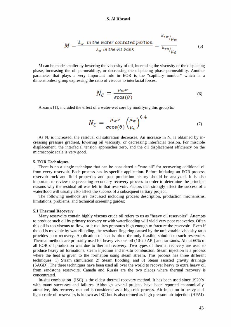
In the steam flooding process shown in Fig. 4, steam is continuously introduced into injection wells to reduce the oil viscosity and to mobilize oil towards the producing wells.
The injected steam forms a steam zone that advances slowly. The injected steam at the surface may contain about 80% steam and 20% water (i.e., 80% steam quality). When steam is injected into the reservoir, heat is transferred to the oil-bearing formation, the reservoir fluids, and some of the adjacent cap and base rock. Due to this heat loss, some of the steam condenses to yield a mixture of steam and hot water. Ahead of the steam zone, an oil bank forms and moves towards the producing well. In many cases, the injected steam overrides the oil due to gravity. This behavior can render this process less efficient. When steam breakthrough occurs, the steam injection rate is reduced by recompletion of wells or shutting off steam producing intervals. Steam reduces the oil saturation in
44
S. Al Rbeawi
the steam zone to very low values (about 10±%). Some oil is transported by steam distillation. Normal steam flooding practice is to precede and accompany the steam drive by a cyclic steam stimulation of the producing wells.
For both steam stimulation and steam flooding, steam recovers crude oil by heating the crude oil and reducing its viscosity and supplying pressure to drive oil to the producing well. However, the process has several limitations:
Fig. 4 Steam Flooding process. • Oil saturations must be quite high, and the pay zones should be more than 20 feet thick to
minimize heat losses to adjacent formations. • Lighter, less viscous crude oils can be steam flooded, but normally they will not be if the
reservoir will respond to an ordinary waterflood. • Steam flooding is primarily applicable to viscous oils in massive, high permeability
sandstones or unconsolidated sands. • Because of excessive heat losses in the wellbore, steam flooded reservoirs should be as
shallow as possible as long as pressure for sufficient injection rates can be maintained. • Steam flooding is not normally used in carbonate reservoirs. • Since about one-third of the additional oil recovered is consumed to generate the required
steam, the cost per incremental barrel of oil is high. • A low percentage of water-sensitive clays is desired for good injectivity.
The technical screening guides for steam flooding are as follows:
Crude Oil Gravity < 25o API (normal range is 10-25o API) Viscosity > 20 cp (normal range is 100-5,000 cp) Composition Not critical but some light ends will help steam distillation Reservoir Oil Saturation > 500 bbl/acre-ft (or> 40-50% PV) Type of Formation Sand or sandstone with high porosity and permeability preferred Net Thickness > 20 feet Average Permeability > 200 md Transmissibility > 100 md ft/ cp
45
S. Al Rbeawi
Depth 300-5,000 ft Temperature Not critical 5.1.3 In-Situ Combustion
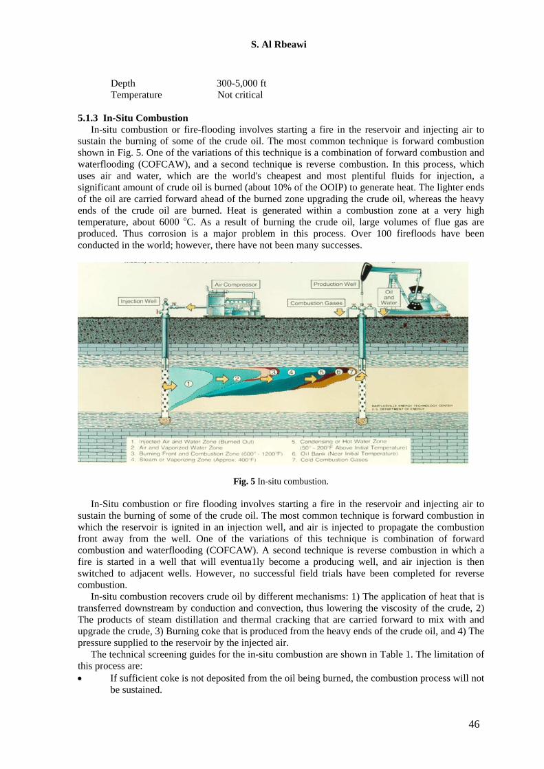
In-situ combustion or fire-flooding involves starting a fire in the reservoir and injecting air to sustain the burning of some of the crude oil. The most common technique is forward combustion shown in Fig. 5. One of the variations of this technique is a combination of forward combustion and waterflooding (COFCAW), and a second technique is reverse combustion. In this process, which uses air and water, which are the world's cheapest and most plentiful fluids for injection, a significant amount of crude oil is burned (about 10% of the OOIP) to generate heat. The lighter ends of the oil are carried forward ahead of the burned zone upgrading the crude oil, whereas the heavy ends of the crude oil are burned. Heat is generated within a combustion zone at a very high temperature, about 6000 oC. As a result of burning the crude oil, large volumes of flue gas are produced. Thus corrosion is a major problem in this process. Over 100 firefloods have been conducted in the world; however, there have not been many successes.
Fig. 5 In-situ combustion.
In-Situ combustion or fire flooding involves starting a fire in the reservoir and injecting air to sustain the burning of some of the crude oil. The most common technique is forward combustion in which the reservoir is ignited in an injection well, and air is injected to propagate the combustion front away from the well. One of the variations of this technique is combination of forward combustion and waterflooding (COFCAW). A second technique is reverse combustion in which a fire is started in a well that will eventua1ly become a producing well, and air injection is then switched to adjacent wells. However, no successful field trials have been completed for reverse combustion.
In-situ combustion recovers crude oil by different mechanisms: 1) The application of heat that is transferred downstream by conduction and convection, thus lowering the viscosity of the crude, 2) The products of steam distillation and thermal cracking that are carried forward to mix with and upgrade the crude, 3) Burning coke that is produced from the heavy ends of the crude oil, and 4) The pressure supplied to the reservoir by the injected air.
The technical screening guides for the in-situ combustion are shown in Table 1. The limitation of this process are: • If sufficient coke is not deposited from the oil being burned, the combustion process will not
be sustained.
46
S. Al Rbeawi
• If excessive coke is deposited, the rate of advance of the combustion zone will be slow, and the quantity of air required to sustain combustion will be high.
• Oil saturation and porosity must be high to minimize heat loss to rock. • Process tends to sweep through upper part of reservoir so that sweep efficiency is poor in
thick formations. Crude Oil Gravity < 40° API (Normally 10-25°) Viscosity < 1000 cp Composition Some asphaltic components to aid coke deposition Reservoir Oil Saturation > 500 bbl/acre-ft (or < 40-50% pv) Type of Formation Sand or sandstone with high porosity Net Thickness > 10 ft Average Permeability > 100 md Transmissibility > 20 md ft/ cp Depth > 500 ft Temperature > 150°F preferred
5.2 Gas Injection
Gas injection process is used for enhanced recovery from light, condensate, and volatile reservoirs. Gas flooding either miscible or immiscible involves injecting a gas to the formations . As a result, the interfacial tension between the two fluids (oil and gas) is very low, and a very efficient microscopic displacement efficiency takes place. The displacing fluid may be hydrocarbon gas that mixes with oil at first contact. For LPG slug or solvent flooding, enriched (condensing) gas drive and high pressure (vaporizing) gas drive, miscibility is achieved at different pressures. Displacement of oil by propane or LPG is miscible at first contact in all proportions. With a high pressure gas (e.g., CO2 or nitrogen), displacement of oil usually takes place by multiple contacts. In recent years the emphasis has been shifting to less valuable non-hydrocarbon gases such as CO2, nitrogen, and flue gases. Although nitrogen and flue gases do not recover oil as well as the hydrocarbon gases (or liquids), the overall economics may be somewhat more favorable. After thermal recovery, miscible flooding contributes the most among various EOR methods. About 40% of the total EOR production is by gas miscible/immiscible flooding. 5.2.1 Hydrocarbon Gas Flooding
As one of the oldest EOR methods, hydrocarbon injection was practiced for years before the (Multiple Miscible Contact) MMP concept was well understood. When a surplus of a low-molecular-weight hydrocarbon existed in some fields, they were often injected to improve oil recovery. In terms of the pressure required for efficient miscible displacement, the hydrocarbon gases were ranked between the very high pressures required for nitrogen and the more modest range of pressures for CO2. This ranking is correct for methane. However, if a shallower reservoir depth requires a lower pressure, it can be achieved by adding more enriching hydrocarbons (usually C2-C4 if the economics permits).
Hydrocarbon miscible flooding consists of injecting light hydrocarbons through the reservoir to form a miscible flood. Three different methods are used : 1- Sometimes in the first LPG Slug Method, water is injected with the chase gas in a WAG
(alternating water and gas) mode to improve mobility ratio between the solvent slug and the chase gas.
2- In the second Enriched (Condensing) Gas Drive method, the enriching components are transferred from the gas to the oil. A miscible zone is formed between the injected gas and the reservoir oil, and this zone displaces the oil ahead.
3- In the third High Pressure (Vaporizing) Gas Drive method, components from the crude oil being displaced result in multiple contact miscibility. Hydrocarbon miscible flooding consists of injecting light hydrocarbons through the reservoir to
form a miscible flood. Three different methods are used. One method uses about 5% PV slug of
47
S. Al Rbeawi
liquified petroleum gas (LPG) such as propane, followed by natural gas or gas and water. A second method, called Enriched (Condensing) Gas Drive, consists of injecting a 10-20% PV slug of natural gas that is enriched with ethane through hexane (C2 to C6), followed by lean gas (dry, mostly methane) and possibly water. The enriching components are transferred from the gas to the oil. The third method, called High Pressure (Vaporizing) Gas Drive, consists of injecting lean gas at high pressure to vaporize C2 - C6 components from the crude oil being displaced.
The mechanisms for the hydrocarbon gas flooding are represented by Generating miscibility (in the condensing and vaporizing gas drive), Increasing the oil volume (swelling), and Decreasing the viscosity of the oil. The limitations of this process are: • The minimum depth is set by the pressure needed to maintain the generated miscibility. The required pressure ranges from about 1,200 psi for the LPG process to 3,000-5,000 psi for the High Pressure Gas Drive, depending on the oil. • A steeply dipping formation is very desirable to permit some gravity stabilization of the displacement that normally has an unfavorable mobility ratio.
The technical screening guides for the hydrocarbon gases injection are as follows:
Crude Oil Gravity > 35° API Viscosity < 10 cp Composition High percentage of light hydrocarbons (C2- C7) Reservoir Oil Saturation > 30% PV Type of Formation Sandstone or carbonate with a minimum of fractures and high permeability streaks Net Thickness Relatively thin unless formation is steeply dipping Permeability Not critical if uniform Depth > 2,000 ft (LPG) to > 5,000 ft (High Pressure Gas) Temperature Not critical 5.2.2 Carbon Dioxide Flooding
In the CO2 miscible flooding process, a volume of a relatively pure CO2 is injected to mobilize and displace residual oil. Through multiple contacts between the CO2 and the oil phase, intermediate and higher molecular weight hydrocarbons are extracted into the CO2 rich phase. Under proper conditions, this CO2 – rich phase will reach a composition that is miscible with the original reservoir oil. From that point, miscible or near miscible conditions exist at the displacing front interface. Under ideal conditions, this miscibility conditions will be reached very quickly in the reservoir and the distance required to establish the multiple-contact miscibility initially is negligible compared with the distance between wells.
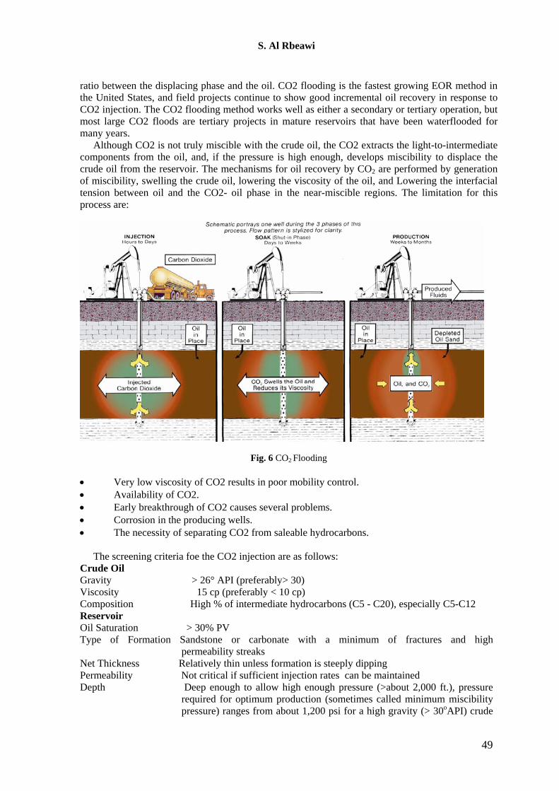
Carbon dioxide flooding is carried out by injecting large quantities of CO2 (15% or more of the hydrocarbon PV) into the reservoir as shown in Fig. 6. Miscible displacement by carbon dioxide is similar to vaporizing gas drive. The only difference is a wider range of components; C2 to C30 are extracted. As a result, CO2 flood process is applicable to a wider range of reservoirs at lower miscibility pressures than those for the vaporizing gas drive. CO2 is generally soluble in crude oils at reservoir pressures and temperatures. It swells the net volume of oil and reduces its viscosity even before miscibility is achieved by vaporizing gas drive mechanism. As miscibility is approached as a result of multiple contacts, both the oil phase and the CO2 phase (containing intermediate oil components) can flow together because of the low interfacial tension. One of the requirements of the development of miscibility between the oil and CO2 is the reservoir pressure.
CO2 flooding should be used in moderately light-oil reservoirs (API gravity> 25), and the reservoir should be deep enough to have high enough pressure to achieve miscibility. CO2 can dissolve in water; thus, it can lower the interfacial tension between oil and water. However, this process can also lead to more corrosion problems. In this process, about 20-50% of the CO2 slug is followed by chase water. Water is generally injected with CO2 in a WAG mode to improve mobility
48
S. Al Rbeawi
ratio between the displacing phase and the oil. CO2 flooding is the fastest growing EOR method in the United States, and field projects continue to show good incremental oil recovery in response to CO2 injection. The CO2 flooding method works well as either a secondary or tertiary operation, but most large CO2 floods are tertiary projects in mature reservoirs that have been waterflooded for many years.
Although CO2 is not truly miscible with the crude oil, the CO2 extracts the light-to-intermediate components from the oil, and, if the pressure is high enough, develops miscibility to displace the crude oil from the reservoir. The mechanisms for oil recovery by CO2 are performed by generation of miscibility, swelling the crude oil, lowering the viscosity of the oil, and Lowering the interfacial tension between oil and the CO2- oil phase in the near-miscible regions. The limitation for this process are:
Fig. 6 CO2 Flooding
• Very low viscosity of CO2 results in poor mobility control. • Availability of CO2. • Early breakthrough of CO2 causes several problems. • Corrosion in the producing wells. • The necessity of separating CO2 from saleable hydrocarbons.
The screening criteria foe the CO2 injection are as follows:
Crude Oil Gravity > 26° API (preferably> 30) Viscosity 15 cp (preferably < 10 cp) Composition High % of intermediate hydrocarbons (C5 - C20), especially C5-C12 Reservoir Oil Saturation > 30% PV Type of Formation Sandstone or carbonate with a minimum of fractures and high
permeability streaks Net Thickness Relatively thin unless formation is steeply dipping Permeability Not critical if sufficient injection rates can be maintained Depth Deep enough to allow high enough pressure (>about 2,000 ft.), pressure
required for optimum production (sometimes called minimum miscibility pressure) ranges from about 1,200 psi for a high gravity (> 30oAPI) crude
49
S. Al Rbeawi
at low temperatures to over 4,500 psi for heavy crudes at higher temperatures.
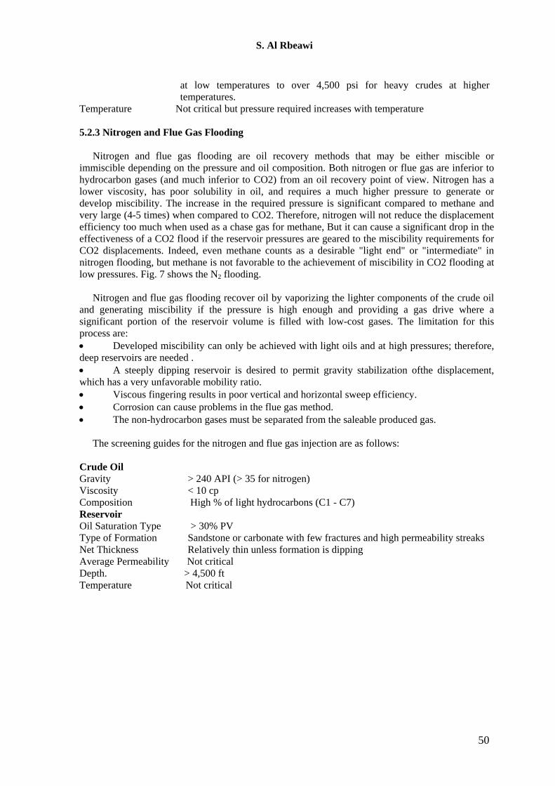
Temperature Not critical but pressure required increases with temperature 5.2.3 Nitrogen and Flue Gas Flooding
Nitrogen and flue gas flooding are oil recovery methods that may be either miscible or
immiscible depending on the pressure and oil composition. Both nitrogen or flue gas are inferior to hydrocarbon gases (and much inferior to CO2) from an oil recovery point of view. Nitrogen has a lower viscosity, has poor solubility in oil, and requires a much higher pressure to generate or develop miscibility. The increase in the required pressure is significant compared to methane and very large (4-5 times) when compared to CO2. Therefore, nitrogen will not reduce the displacement efficiency too much when used as a chase gas for methane, But it can cause a significant drop in the effectiveness of a CO2 flood if the reservoir pressures are geared to the miscibility requirements for CO2 displacements. Indeed, even methane counts as a desirable "light end" or "intermediate" in nitrogen flooding, but methane is not favorable to the achievement of miscibility in CO2 flooding at low pressures. Fig. 7 shows the N2 flooding.
Nitrogen and flue gas flooding recover oil by vaporizing the lighter components of the crude oil
and generating miscibility if the pressure is high enough and providing a gas drive where a significant portion of the reservoir volume is filled with low-cost gases. The limitation for this process are: • Developed miscibility can only be achieved with light oils and at high pressures; therefore, deep reservoirs are needed . • A steeply dipping reservoir is desired to permit gravity stabilization ofthe displacement, which has a very unfavorable mobility ratio. • Viscous fingering results in poor vertical and horizontal sweep efficiency. • Corrosion can cause problems in the flue gas method. • The non-hydrocarbon gases must be separated from the saleable produced gas.
The screening guides for the nitrogen and flue gas injection are as follows:
Crude Oil Gravity > 240 API (> 35 for nitrogen) Viscosity < 10 cp Composition High % of light hydrocarbons (C1 - C7) Reservoir Oil Saturation Type > 30% PV Type of Formation Sandstone or carbonate with few fractures and high permeability streaks Net Thickness Relatively thin unless formation is dipping Average Permeability Not critical Depth. > 4,500 ft Temperature Not critical
50
S. Al Rbeawi
Fig. 7 N2 injection process 5.3 Chemical Flooding
Chemical flooding processes comes in the second rank of all EOR projects all over the world. It has been used for both carbonate and sandstone formations. The 1980s was considered as the best time (peak) for the oil recovery by chemical flooding. These processes require conditions favorable to water injection because they are modifications of waterflooding. Chemical flooding is applicable to oils that are more viscous than oils suitable for gas injection, but less viscous than oils that can be recovered by thermal methods. Reservoirs with moderate permeability are desirable. The presence of a gas cap is not desirable, since there is the potential of re-saturating the cap. Formations with high clay contents are undesirable, since the clays increase the adsorption of the injected chemicals.
Three type of chemicals have been used in the chemical flooding. Polymers group is the mostly used type for different formation where there is serous need to improve the swept efficiency. Surfactants group is the second type of chemical that has been used in the formations where there is serous need to reduce the interfacial tension between oil and water. Mixed polymer and surfactant (SP) solutions, also known as micellar flooding or micro-emulsion flooding, are commonly used. Caustic solutions group, also known as alkaline solutions group, is the third type of chemical flooding. A combination of polymer-surfactant-alkaline (ASP) may be used.
5.3.1 Polymer Flooding
The objective of polymer flooding is to provide better displacement and volumetric sweep efficiencies during a waterflood. The mechanisms for oil recovery improvement by polymer are increasing the viscosity of water, decreasing the mobility of water, contacting a larger volume of the reservoir, and reducing the injected fluid mobility to improve areal and vertical sweep efficiencies.
It should be noted that polymer does not lower the residual oil saturation. Because polymer flooding inhibits fingering, the oil displacement is more efficient in the early stages as compared to a conventional waterflood. As a result, more oil will be produced in the early life of the flood. This is the primary economic advantage because it is generally accepted that ultimate recovery will be the same for polymer flooding as for waterflooding.
Many factors affect polymer flooding. These include polymer degradation due to salinity, temperatures, time, shear rates, and the presence of divalent ions. Some polymers, like polysaccharides, are more resistant; however, they suffer from bacterial degradation problems and cause wellbore plugging. Also, polymers may be lost in the formation due to adsorption. Polymers
51
S. Al Rbeawi
may be ineffective in a mature waterflood because of low mobile oil saturation. They show some promise in a reservoir with high vertical heterogeneity where the oil saturation may still be high and the vertical conformance poor. Some operators have been successful in treating injection wells (near-well treatment) with polymers to modify vertical profiles.
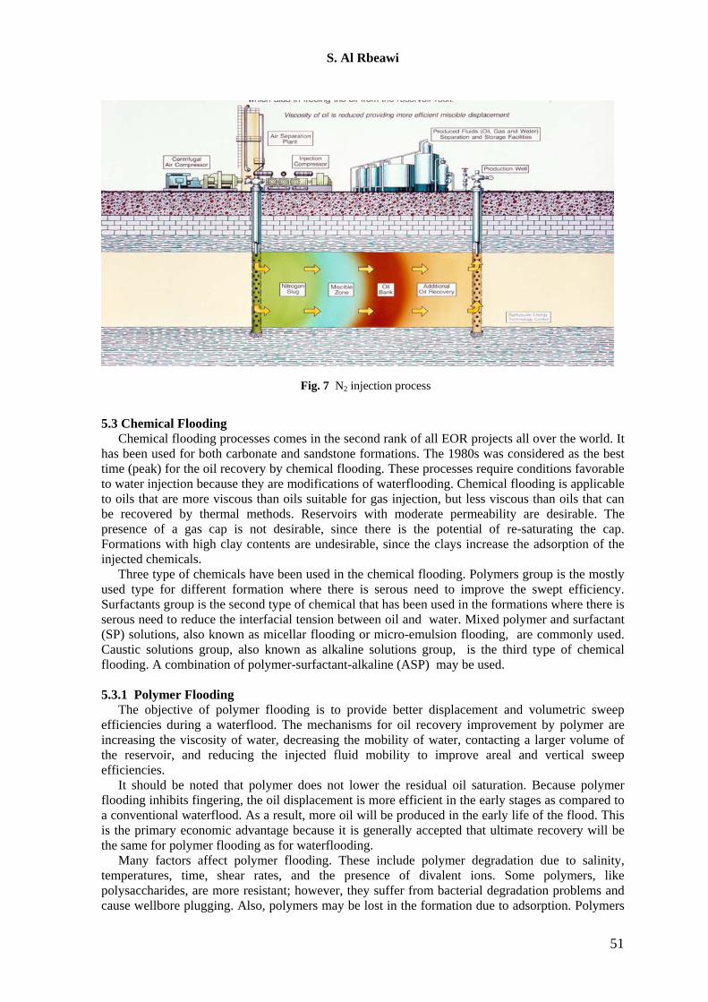
Polymer augmented waterflooding consists of adding water soluble polymers to the water before it is injected into the reservoir. Low concentrations (often 250-2,000 mg/L) of certain synthetic or biopolymers are used; properly sized treatments may require 15 - 25% reservoir PV. Fig. 8 shows polymer flooding. The limitations of the polymer flooding process are: • If oil viscosities are high, a higher polymer concentration is needed to achieve the desired
mobility control. • Results are normally better if the polymer flood is started before the water-oil ratio becomes
excessively high. • Clays increase polymer adsorption. • Some heterogeneity is acceptable but for conventional polymer flooding, reservoirs with
extensive fractures should be avoided. If fractures are present, the cross-linked or gelled polymer techniques may be applicable.
• Lower injectivity than with water can adversely affect oil production rate in the early stages of the polymer flood.
• Acrylamide-type polymers lose viscosity due to sheer degradation, or it increases in salinity and divalent ions.
• Xanthan gum polymers cost more, are subject to microbial degradation, and have a greater potential for wellbore plugging.
Fig. 8 Polymer Flooding.
The technical guides for the screening process of the polymer flooding are as follows: Crude oil Gravity > 25° API Viscosity < 150 cp (preferably < 100) Composition Not critical Reservoir Oil Saturation > 10% PV mobile oil
52
S. Al Rbeawi
Type of Formation Sandstone preferred but can be used in carbonate Net Thickness Not critical Permeability >10 md (as low as 3 md in some cases) Depth < about 9000 ft (see Temperature) Temperature < 200°F to minimize degradation 5.3.2 Surfactant Flooding
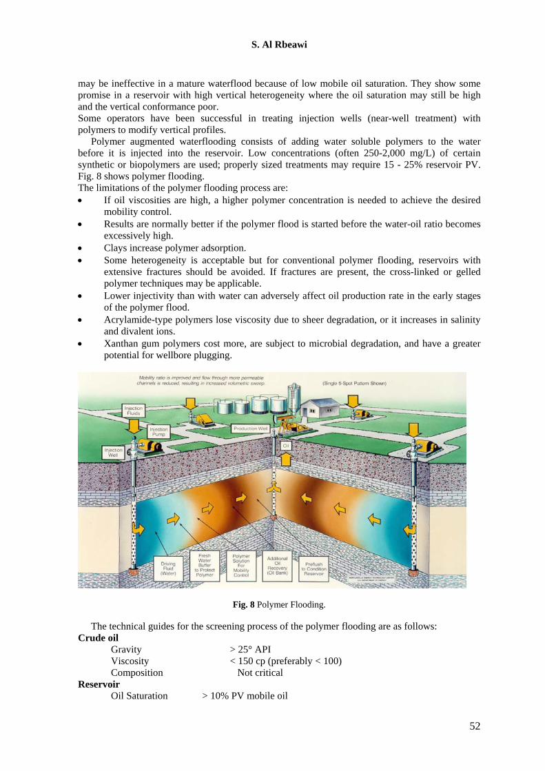
Surfactant/polymer flooding, also called "micellar/polymer" or "micro-emulsion flooding" consists of injecting a slug that contains water, surfactant, electrolyte (salt), usually a cosolvent (alcohol), and possibly a hydrocarbon (oil) . Fig.(9) shows surfactant flooding.
The size of the slug is often 5-15% PV for a high surfactant concentration system and 15-50% PV for low concentrations. The surfactant slug is followed by polymer-thickened water. Concentrations of the polymer often ranges from 500-2,000 sg/L. The volume of polymer solution injected may be 50% PV, more or less, depending on the process design. The mechanisms for oil recover by surfactant/polymer flooding are lowering the interfacial tension between oil and water, solubilization of oil, emulsification of oil and water, and mobility enhancement. The limitations for this process are: • An areal sweep of more than 50% on waterflood is desired. • Relatively homogeneous formation is preferred. • High amounts of anhydrite, gypsum, or clays are undesirable. • Available systems provide optimum behavior over a very narrow set of conditions. • With commercially available surfactants, formation water chlorides should be < 20,000
ppm and divalent ions (Ca++ and Mg++) < 500 ppm.
Fig. 9 Surfactant flooding
The screening criteria for the surfactant flooding are as follows: Crude Oil Gravity > 25° API Viscosity < 30 cp Composition Light to intermediates are desirable Reservoir Oil Saturation > 30% PV Type of Formation Sandstone preferred Net Thickness > 10 ft
53
S. Al Rbeawi
Average Permeability > 20 md Depth < about 8,000 ft Temperature < 175°F 5.3.3 Caustic Flooding
Caustic or alkaline flooding involves the injection of chemicals such as sodium hydroxide, sodium silicate, or sodium carbonate. Oils in the API gravity range of 13 – 35o are normally the target for alkaline flooding. One of the desirable properties for the oils is to have enough organic acids so that they can react with the alkaline solution. Another desirable property is moderate oil gravity so that mobility control is not a problem.
Sandstone reservoirs are generally preferred for this process, since carbonate formations often contain anhydride or gypsum which consume a large amount of alkaline chemicals. The alkali is also consumed by clays, minerals, or silica. In addition, the consumption is high at elevated temperatures. Another problem with caustic flooding is the scale formation in the producing wells.
Alkaline solutions react With organic petroleum acids in certain crudes to create surfactants in situ. They also react With reservoir rocks to change wettability. The concentration of the alkaline agent is normally 0.2 to 5%; slug size is often 10 to 50% PV, although one successful flood only used 2% PV, (but this project also included polymers for mobility control). Polymers may be added to the alkaline mixture, and polymer-thickened water can be used following the caustic slug. Oil is recovered by alkaline solution throughout different mechanisms. These mechanisms are a reduction of interfacial tension resulting from the produced surfactants, changing wettability from oil-wet to water-wet, changing wettability from water-wet to oil-wet, emulsification and entrainment of oil, emulsification and entrapment of oil to aid in mobility control, and solubilization of rigid oil films at oil-water interfaces. However, not all mechanisms are operative in each reservoir.
The limitations for alkaline flooding process are: • Best results are obtained if the alkaline material reacts With the crude oil; the oil should have
an acid number of more than 0.2 mg KOH/g of oil. • The interfacial tension between the alkaline solution and the crude oil should be less than
0.01 dyne/cm. • At high temperatures and in some chemical environments, excessive amounts of alkaline
chemicals may be consumed by reaction With clays, minerals, or silica in the sandstone reservoir.
• Carbonates are usually avoided because they often contain anhydrite or gypsum, which interact adversely With the caustic chemical. The screening guides for the chemical flooding techniques are as follows:
Crude Oil Gravity 13° to 35° API Viscosity < 200 cp Composition Some organic acids required Reservoir Oil Saturation Above waterflood residual Type of Formation Sandstones preferred Net Thickness Not critical Average Permeability > 20 md Depth . < about 9,000 ft (see Temperature) Temperature < 200°F preferred 5.4 Special EOR techniques 5.4.1 Water-Alternative-Gas Injection (WAG)
WAG is one of the most important techniques used in low dip reservoirs. This process involves injecting alternating cycles of gas and water. The underlying principle is based on the experimental fact that the total mobility of a two-phase system is less than single-phase mobility by proper choice of ratio of the volumes injected. An ideal situation can be created where the displacing
54
S. Al Rbeawi
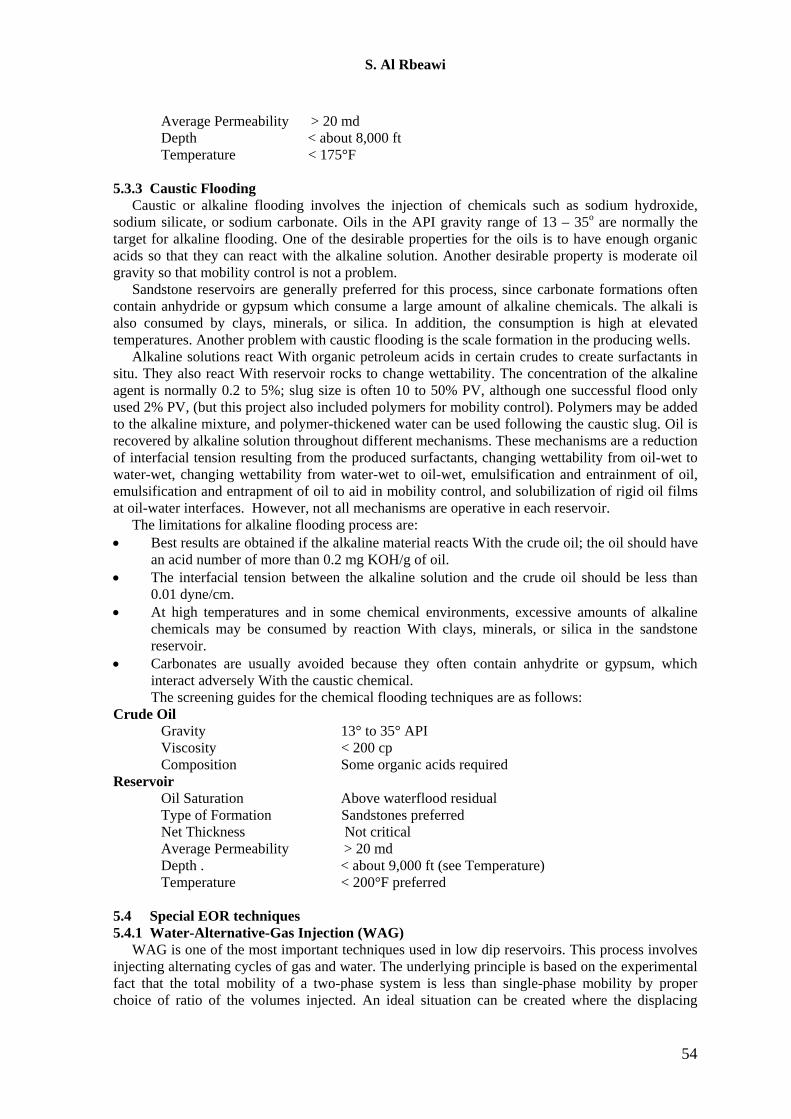
mixture of gas and water has the lowest mobility, which works better than even water injection. In practical, gravity segregation and reservoir heterogeneity tend to limit the development of such uniform displacements. The WAG technique may result in high oil recovery in horizontal reservoirs. One of the advantages of the WAG technique is that it allows maximizing the contacted volume for a given volume of gas available. This could be important in situations where we have limited supply of gas, where the only gas available is the gas produced from the field with no external supply.
Important factors affecting water-alternating gas injection are reservoir and fluid properties, miscibility conditions, injection technique and WAG parameters, screening of WAG injection is based on accounting of specific reservoir conditions, particular reservoir and fluid properties. Oil recovery by the injection of water alternately with gas (WAG flooding) is often limited by gravity segregation, which causes the injected gas to rise to the top of the formation and water to migrate to the bottom. This segregation results in a miscible flood in only a thin layer at the top of the formation, whereas the remainder is waterflooded. However, vertical conformance in a WAG flood can be greatly improved by use of injection rates that are high relative to well spacing. The degree of improvement and, hence, the resultant oil recovery is primarily a function of a single dimensionless parameters, which is one form of the viscous-gravity ratio.
Optimum conditions of oil displacement by WAG would be achieved if the gas and water travel in the reservoir at equal velocity. The effect may occur for a short time in the water-gas mixture zone but has a limited extent in the reservoir because of difference in viscous and gravity forces. Therefore portioning of water/gas banks and cycling are required to tune the injection scheme for particular reservoir conditions. The decrease of gas bank volume injected in altered cycles with water into high permeability layer increases the trapped volume of gas in the layer. This limits the amount of segregated gas that can be injected to the upper layer, thus the increase of WAG ratio and of WAG cycles give improved oil recovery from the low permeability layer at the expend of recovery from the low permeability top layer. Fig. 10 shows the water-alternative-gas injection process (WAG).
Fig. 10 WAG Flooding process
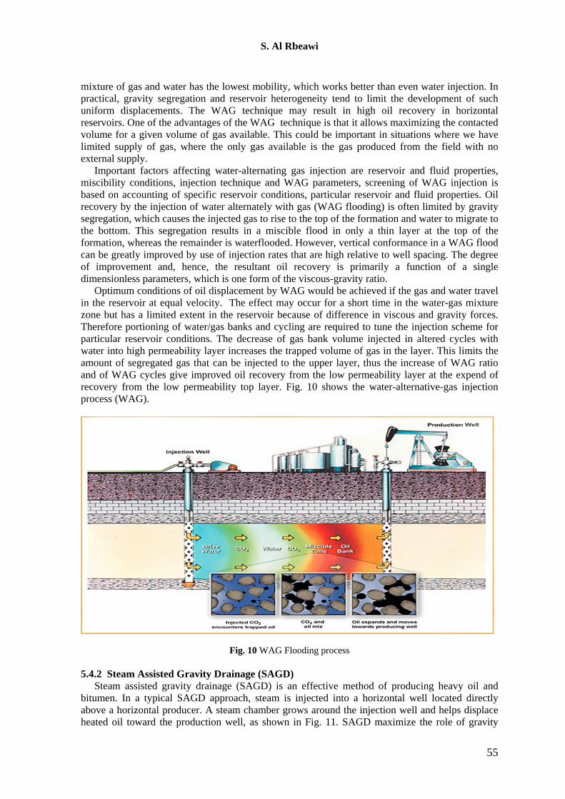
5.4.2 Steam Assisted Gravity Drainage (SAGD) Steam assisted gravity drainage (SAGD) is an effective method of producing heavy oil and
bitumen. In a typical SAGD approach, steam is injected into a horizontal well located directly above a horizontal producer. A steam chamber grows around the injection well and helps displace heated oil toward the production well, as shown in Fig. 11. SAGD maximize the role of gravity
55
S. Al Rbeawi
forces during steam flooding of heavy oils. Heat is transferred by conduction, convection, and latent heat of the steam. By injecting steam, a steam chamber forms directly above the production well. At the steam chamber boundary, steam condenses to water as heat is transferred to the oil. Condensed water and hot oil flow along the steam chamber to the production well.
Fig. 11 Steam Assisted Gravity drainage (SAGD) process
5.4.3 Microbial Flooding (MEOR)
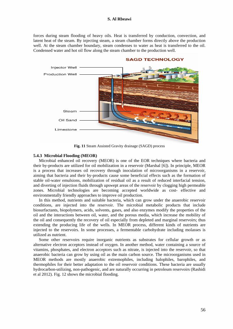
Microbial enhanced oil recovery (MEOR) is one of the EOR techniques where bacteria and their by-products are utilized for oil mobilization in a reservoir (Marshal [6]). In principle, MEOR is a process that increases oil recovery through inoculation of microorganisms in a reservoir, aiming that bacteria and their by-products cause some beneficial effects such as the formation of stable oil-water emulsions, mobilization of residual oil as a result of reduced interfacial tension, and diverting of injection fluids through upswept areas of the reservoir by clogging high permeable zones. Microbial technologies are becoming accepted worldwide as cost- effective and environmentally friendly approaches to improve oil production.
In this method, nutrients and suitable bacteria, which can grow under the anaerobic reservoir conditions, are injected into the reservoir. The microbial metabolic products that include biosurfactants, biopolymers, acids, solvents, gases, and also enzymes modify the properties of the oil and the interactions between oil, water, and the porous media, which increase the mobility of the oil and consequently the recovery of oil especially from depleted and marginal reservoirs; thus extending the producing life of the wells. In MEOR process, different kinds of nutrients are injected to the reservoirs. In some processes, a fermentable carbohydrate including molasses is utilized as nutrient.
Some other reservoirs require inorganic nutrients as substrates for cellular growth or as alternative electron acceptors instead of oxygen. In another method, water containing a source of vitamins, phosphates, and electron acceptors such as nitrate, is injected into the reservoir, so that anaerobic bacteria can grow by using oil as the main carbon source. The microorganisms used in MEOR methods are mostly anaerobic extremophiles, including halophiles, barophiles, and thermophiles for their better adaptation to the oil reservoir conditions. These bacteria are usually hydrocarbon-utilizing, non-pathogenic, and are naturally occurring in petroleum reservoirs (Rashidi et al 2012). Fig. 12 shows the microbial flooding.
56
S. Al Rbeawi
Fig. 12 Microbial flooding pocess
Several publications state that oil recovery through microbial action takes place due to several mechanisms as follows (Jackson et al [3] and Nielson et al [7]): 1- Reduction of oil/water interfacial tension and modification of porous media wettability by surfactant production and bacterial action. 2- Selective plugging of porous media by microorganisms and their metabolites. 3- Oil viscosity reduction caused by gas solution in the oil due to bacterial gas production or degradation of long-chain saturated hydrocarbons. 4- Production of acids that dissolve rock improving porous media permeability. 5.4.4 Nanofluid injection
New type of fluids usually called “smart fluids” has become more accessible for the oil and gas industry. The nanofluids are created by the addition of nanoparticles to fluids for intensification and improvement of some properties at low volume concentrations of the dispersing medium. Then the main feature of nanofluids is that their properties greatly depend on the dimensions of nanoparticles. Suspensions of nanodimensional particles have the following advantages; increase in sedimentation stability because surface forces easily counterbalance the force of gravity; thermal, optical, stress–strain, electrical, rheological and magnetic properties that strongly depend on size and shape of the nanoparticles can be created during production. It is for this reason that nanofluid properties often exceed the properties of conventional fluids. The researches have shown how dispersed nanoparticles in an aqueous phase can modify the interfacial properties of the liquid/liquid systems if their surface is modified by the presence of an ionic surfactant. Mixed particle/surfactant interfacial layers have been characterized through measurements of the effective interfacial tension and wettability (Onyekonwu et al [9]).
Presence of nanoparticles changes rheological properties and increase effect of surfactant solution on oil recovery processes. First of all it changes interfacial tension value of surfactant/oil interface more effectively. Observed reduction of interfacial tension is the result of nanoparticles presence at the interfacial layers. In lower concentration of nanoparticle, they are attached to the liquid surface and due to absorption process decrease surface tension. However in concentration larger than 0.4 wt.%, the nanoparticles nearly completely remove the surfactant from the bulk aqueous phase and there is no free surfactant available in the bulk. Thus, for nanoparticles concentrations below 0.4 wt.%, the interfacial tension of the dispersion is determined by a mixed layer composed by attached nanoparticles and surfactant adsorbed at the liquid interface (Ogolo et al [8]).
57
S. Al Rbeawi
Haroun et al [4] explained that the nanotechnology EOR has the following advantages over the other techniques: • Low viscosity oil • High salinity • Large well spacing • High clay content • Extensive thermal fracture 6. Iraqi oil Fields
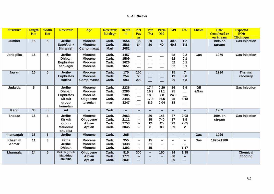
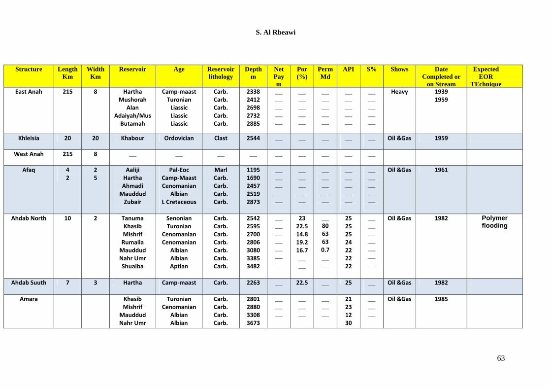
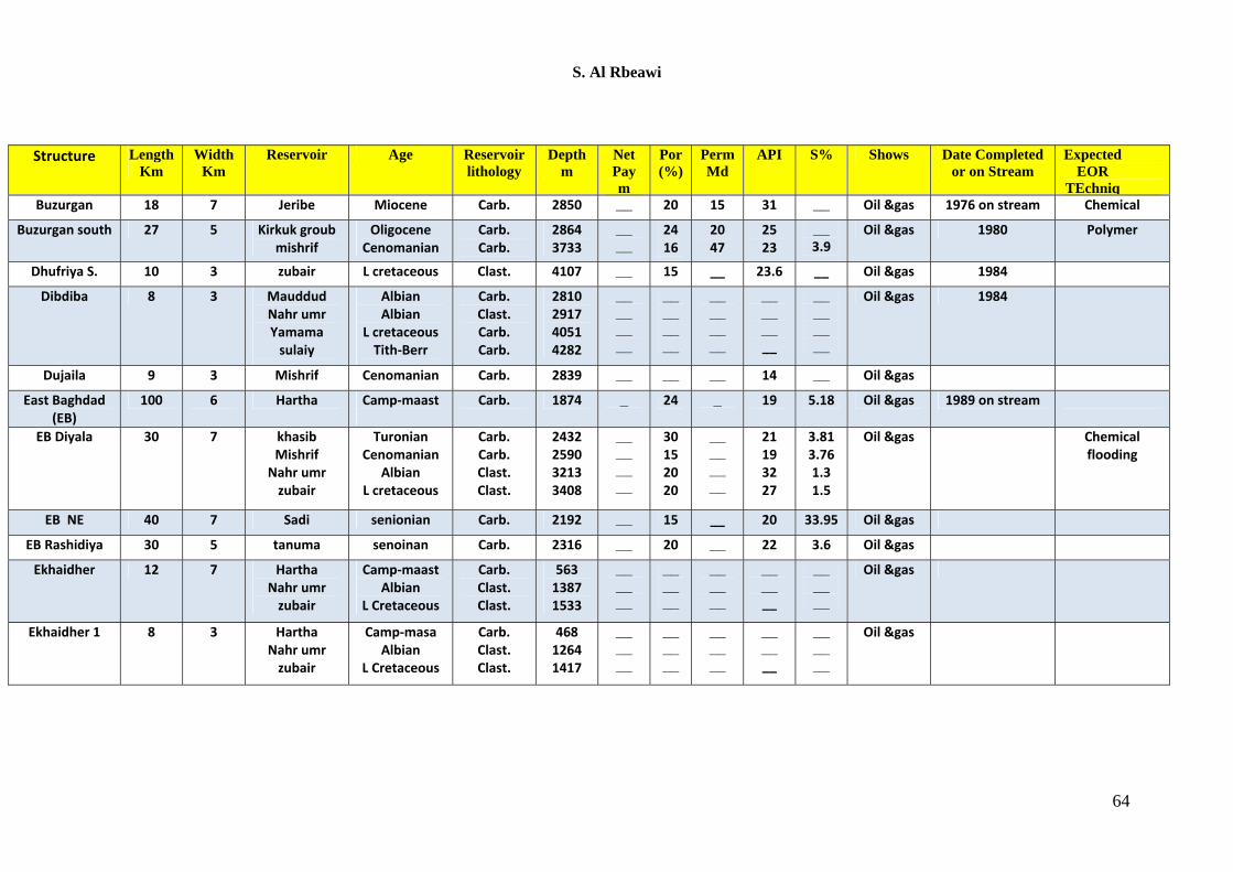
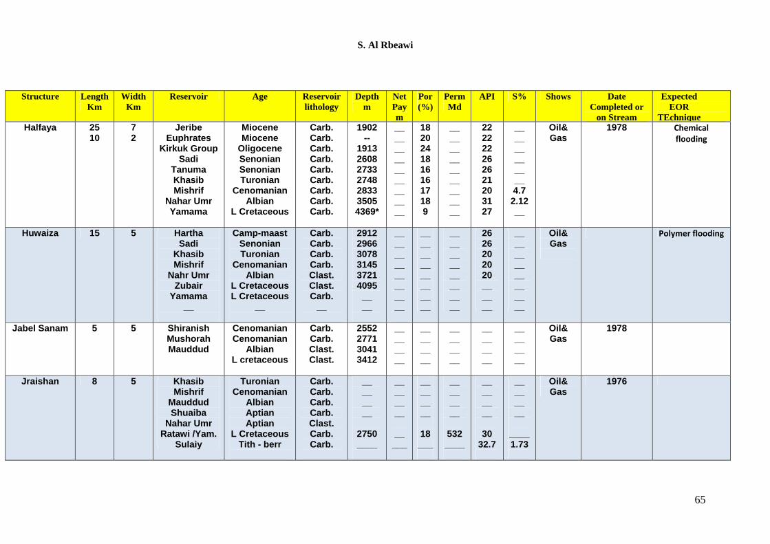
It is well known that the majority of Iraqi oil fields are having carbonate lithology. However, sandstone formations are existed also in several Iraqi oil fields. Iraqi oil is considered as moderate to light oil in which the API gravity covers the range (20-35). Very few Iraqi oils are classified as heavy oil like the oil produced from Qaiyarah structure (Jeribe reservoir 15.3 API, Euphrates reservoir 15.3 API, and Hartha reservoir 17.3 API). At the same time, very few oils are considered light oil with API gravity around 40 such as the oils from Ajeel structure (Fatha reservoir 41 API, Gotnia 37 API, and Sargelu 38 API).
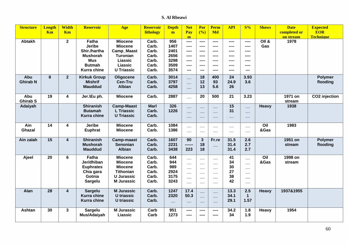
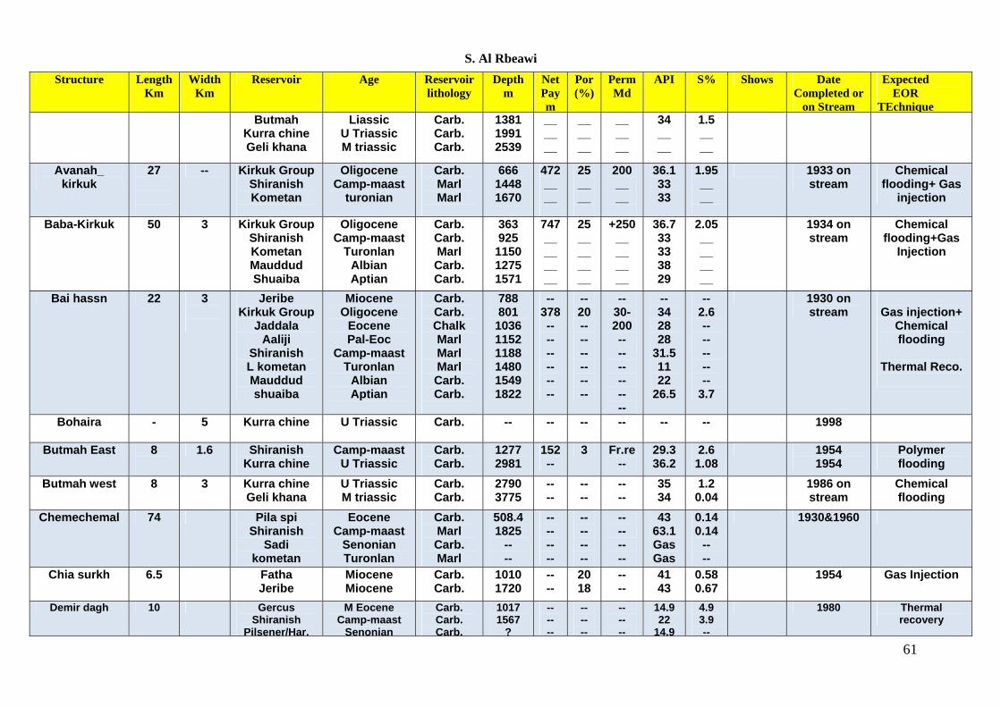
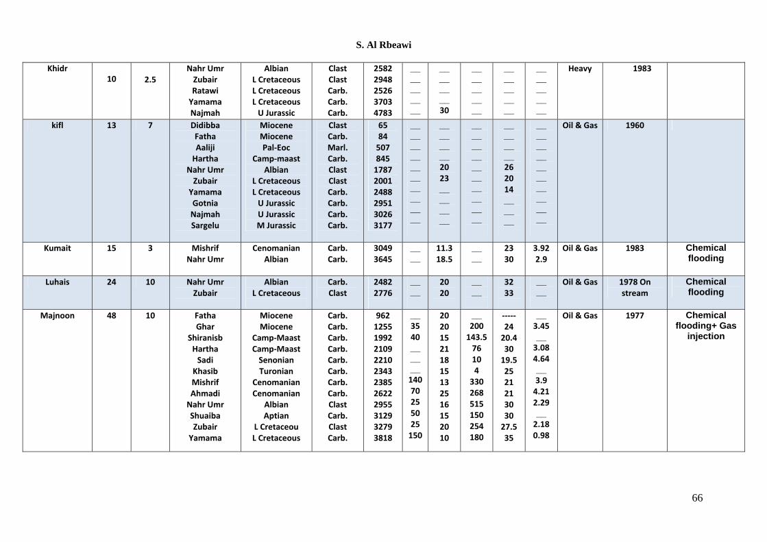
Based on the lithology type, both gas injection techniques and chemical flooding processes are good candidates for the enhanced oil recovery treatment in Iraqi oil fields. The consideration should be taken for the permeability rang and the viscosity of the oil. The permeability of most Iraqi oil fields is in the range of several milidarcies to almost one Darcy. Naturally fractured carbonate reservoirs is the second consideration for the screening criteria of the enhanced oil recovery process in the Iraqi oil fields. Appendix-A shows classification for Iraqi oil fields based on structure, length, width, reservoir, lithology, depth, net pay thickness, porosity, permeability, API, sulfur content, and the produced fluid. This classification might be used for screening criteria of the prospective EOR projects. Three technical selection criteria have to be considered. Lithology is the first selection criterion for the EOR projects where thermal flooding is the dominant technique for sandstone reservoirs while gas injection is the best candidate for the carbonate reservoirs. The second criterion is the reservoir fluid properties in which the API gravity and the viscosity are the two parameters that typical taken into account. The third one is the formation properties in which the porosity and permeability ranges are the main factors for the selection of the EOR projects. Reservoir depth also has some impacts on the selection criteria as the pressure and temperature gradient depend on the depth.
Nomenclatures
58
S. Al Rbeawi
59
References 1. Abrams A., ‘The Influence of Fluid Viscosity, Interfacial Tension, and Flow Velocity on Residual Oil
Saturation Left by Waterflood’, SPE Journal, (1975), 437-447. 2. Alvarado, V. and Manrique, E:, ‘Enhanced Oil Recovery: An Update Review’, Energies, 3 (2010), 1529-
1575. 3. Jackson S.C. et al , ‘Consideration for Field Implementation of Microbial Enhanced Oil Recovery’, SPE
144483 paper presented at the Annual Technical Conference and Exhibition held in Denver, Colorado, USA, 30 Oct.-2 Nov, 2011.
4. Haroun M. et al , ‘Smart Nano-EOR Process for Abu Dhabi Carbonate Reservoirs’. SPE 162386 paper prsented at the Abu Dhabi International Petroleum Exhibition and Conference held in Abu Dhabi, UAE, 11-14 Nov, 2012.
5. Manrique E. et al, ‘EOR: Current Status and Opportunities’ , SPE 130113 paper presented at the 2010 SPE Improved Oil Recovery held in Tulsa, Oklahoma, USA, 24-28 April,2010.
6. Marshal S.L.,‘Fundamental Aspect of Microbial Enhanced Oil Recovery: A National Research Flagship: wealth from ocean’, CSIRO, Australia, March, 2008.
7. Nielsen S.M. et al, ‘Microbial Enhanced Oil Recovery: 3D Simulation with gravity effect’, SPE-131048 paper presented at the SPE EURPOEC/EAGE Annual Conference and Exhibition held in Barcelona, Spain, 14-17, June, 2010.
8. Ogolo N.A., Olafuyi O.A. and Onyekonwu M.O., ‘Enhanced Oil Recovery Using Nanoparticles, SPE 160847 paper presented at the SPE Saudi Arabia Section Technical Symposium and Exihibition held in Al-Khobar, Saudi Arabia, 8-11 April, 2012.
9. Onyekonwu M.O. and Ogolo N.A., ‘Investigating the Use of Nanoparticles in Enhanced Oil Recovery’ , SPE 140744 paper presented at the 34th Annual Technical Conference and Exhibition held in Tinapa, Calabar, Nigeria , 31 Jul.- 7 Aug, 2010.
10. Rashedi H., Yazdian F., and Naghizadeh S., ‘Microbial Enhanced Oil Recovery, Introduction to Enhanced Oil Recovery (EOR) Processes and Bioremediation of Oil-Contaminated Sites, InTech’, Available from: http://www.intechopen.com/books/ introduction-to enhanced-oil-recovery-processes-and-bioremediationof-oil contaminated -sites/microbial-enhanced-oil-recovery, 2010.
Appendix
S. Al Rbeawi
Structure Length Km
Width Km
Reservoir Age Reservoir lithology
Depth m
Net Pay m
Por (%)
Perm Md
API S% Shows Date completed or
on stream
Expected EOR
Technique Abtakh 2 Fatha
Jeribe Shir./hartha Mushorah
Mus Butmah
Kurra chine
Miocene Miocene
Camp_Maast Turonian Liassic Liassic
U Triassic
Carb. Carb. Carb. Carb. Carb. Carb. Carb.
956 1407 2401 2656 3298 3509 3574
---- ---- ---- ---- ---- ---- ---
---- ---- ---- ---- ---- ---- ---
---- ---- ---- ---- ---- ---- ----
---- ---- ---- ---- ---- ---- ----
---- ---- ---- ---- ---- ---- ---
OIl & Gas
1978
Abu Ghirab N
8 2 Kirkuk Group Mishrif
Mauddud
Oligocene Cen-Tru Albian
Carb. Carb. Carb.
3014 3797 4258
__ __ __
18 12 13
400 93 5.6
24 24.9 26
3.93 3.6
Polymer flooding
Abu Ghirab S
19 4 Jer.\Eu ph. Miocene
Carb. 2887 __
20 500 21 3.23 1971 onstream
CO2 injection
Adaiyah Shiranish Butamah
Kurra chine
Camp-Maast L Triassic U Triassic
Marl Carb. Carb.
326 1226
__ __ __
__ __ __
__ __ __
15 31 __
__ __ __
Heavy 1938
Ain Ghazal
14 4 JeribeEuphrat
Miocene Miocene
Carb. Carb.
1084 1386
__ __
__ __
__ __
__ __
__ __
Oil &Gas
1983
Ain zalah 15 4 Shiranish Mushorah Mauddud
Camp-maast Senonian
Albian
Carb. Carb. Carb.
1607 2231 3438
90 ------ 223
3 18 18
Fr.re __
31.5 31.4 31.4
2.6 2.7 2.7
1951 on stream
Polymer flooding
Ajeel 20 6 FathaJer/dhiban Euphrates Chia gara
Gotnia Sargelu
Miocene Miocene Miocene Tithonian
U Jurassic M Jurassic
Carb. Carb. Carb. Carb. Carb. Carb.
644 944 989 2924 3175 3243
__ __ __ __ __ __
__ __ __ __ __ __
__ __ __ __ __ __
41 34 30 27 38 42
__ __ __ __ __ __
Oil &Gas
1998 on stream
AIan 28 4 Sargelu Kurra chine Kurra chine
M Jurassic U triassic U triassic
Carb. Carb. Carb.
1247 2320
__
17.4 50.3 __
__ __ __
__ __ __
13.3 34.1 29.1
2.5 1
1.57
Heavy 1937&1955
Ashtan 30 3 Sargelu Mus/Adaiyah
M Jurassic Liassic
Carb Carb
951 1273
---- ----
---- ----
---- ----
34.2 34
1.8 1.9
Heavy 1954
60
S. Al Rbeawi
61
Structure Length Km
Width Km
Reservoir Age Reservoir lithology
Depth m
Net Pay m
Por (%)
Perm Md
API S% Shows Date Completed or
on Stream
Expected EOR
TEchnique Butmah
Kurra chine Geli khana
Liassic U Triassic M triassic
Carb. Carb. Carb.
1381 1991 2539
__ __ __
__ __ __
__ __ __
34 __ __
1.5 __ __
Avanah_ kirkuk
27
-- Kirkuk Group Shiranish Kometan
Oligocene Camp-maast
turonian
Carb. Marl Marl
666 1448 1670
472 __ __
25 __ __
200 __ __
36.1 33 33
1.95 __ __
1933 on stream
Chemical flooding+ Gas
injection
Baba-Kirkuk
50 3
Kirkuk Group Shiranish Kometan Mauddud Shuaiba
Oligocene Camp-maast
Turonlan Albian Aptian
Carb. Carb. Marl Carb. Carb.
363 925
1150 1275 1571
747 __ __ __ __
25 __ __ __ __
+250 __ __ __ __
36.7 33 33 38 29
2.05 __ __ __ __
1934 onstream
Chemical flooding+Gas
Injection
Bai hassn 22 3
Jeribe Kirkuk Group
Jaddala Aaliji
Shiranish L kometan Mauddud shuaiba
Miocene Oligocene
Eocene Pal-Eoc
Camp-maast Turonlan
Albian Aptian
Carb. Carb. Chalk Marl Marl Marl Carb. Carb.
788 801
1036 1152 1188 1480 1549 1822
-- 378 -- -- -- -- -- --
-- 20 -- -- -- -- -- --
-- 30-200 -- -- -- -- -- --
-- 34 28 28
31.5 11 22
26.5
-- 2.6 -- -- -- -- --
3.7
1930 on stream
Gas injection+
Chemical flooding
Thermal Reco.
Bohaira - 5 Kurra chine
U Triassic
Carb.
-- -- -- -- -- -- 1998
Butmah East 8
1.6 Shiranish Kurra chine
Camp-maast U Triassic
Carb. Carb.
1277 2981
152 --
3 Fr.re --
29.3 36.2
2.6 1.08
1954 1954
Polymer flooding
Butmah west 8
3 Kurra chineGeli khana
U Triassic M triassic
Carb. Carb.
2790 3775
-- --
-- --
-- --
35 34
1.2 0.04
1986 onstream
Chemical flooding
Chemechemal 74 Pila spi Shiranish
Sadi kometan
Eocene Camp-maast
Senonian Turonlan
Carb. Marl Carb. Marl
508.4 1825
-- --
-- -- -- --
-- -- -- --
-- -- -- --
43 63.1 Gas Gas
0.14 0.14
-- --
1930&1960
Chia surkh 6.5 Fatha Jeribe
Miocene Miocene
Carb. Carb.
1010 1720
-- --
20 18
-- --
41 43
0.58 0.67
1954 Gas Injection
Demir dagh 10 GercusShiranish
Pilsener/Har.
M EoceneCamp-maast
Senonian
Carb.Carb. Carb.
10171567
?
-- -- --
---- --
---- --
14.922
14.9
4.93.9 --
1980 Thermal recovery
S. Al Rbeawi
Structure Length Km
Width Km
Reservoir Age Reservoir lithology
Depth m
Net Pay m
Por (%)
Perm Md
API S% Shows Date Completed or
on Stream
Expected EOR
TEchnique Jumber 15 5 Jeribe
Euph/serik Shiranish
Miocene Miocene
Camp-masat
Carb. Carb. Marl
1554 1586 2082
102 64 __
20 30 __
4 40 __
40.5 40.6 __
1.2 1.3 __
1995 on stream
Gas Injection
Jaria pika 15 5 Jeribe Dhiban
Euphrates serikagni
Miocene Miocene Miocene Miocene
Carb. Carb. Carb. Carb.
1457 1509 1626 1651
__ __ __ __
__ __ __ __
__ __ __ __
48 52 52 52
2.2 0.1 0.1 0.1
Gas 1976 Gas injection
Jawan 16 5 Jeribe Euphrates
Hartha
Miocene Miocene
Camp-masat
Carb. Carb. Carb.
175 254 693
150 50 200
__ __ __
__ __ __
15 19 20
7 6.8 5.8
1936 Thermal recovery
Judaida 5 1 JeribeDhiban
Euphrates Kirkuk groub
kometan
Miocene Miocene Miocene
Oligocene turonian
Carb. Carb. Carb. Carb. marl
2236 2286 2385 2445 3247
__ __ __ __ __
17.4 16.9 18.5 17.8 8.9
0.29 21.1 7.8 36.5 0.04
26 25
24.9 25 18
2.9 __ __
4.18 __
Oil &Gas
Gas injection
Kand 33 5 nd -- Carb. -- -- -- -- -- -- 1983 khabaz 15 4 Jeribe
Kirkuk groub
Mauddud shuaiba
Miocene Oligocene
Albian Aptian
Carb. Carb. Carb. Carb.
2063 2111 2753 3045
-- -- -- --
20 15 12 8
146 740 25 83
37 37 29 39
2.08 1.5 2.05
2
1994 on stream
Gas injection
khanuaqah 33 3 Jeribe Miocene Carb. 265 -- -- -- -- -- Gas 1929 Khashim Ahmar
11 3 Fatha Jeribe Dhiban
E h t
Miocene Miocene Miocene Mi
Carb. Carb. Carb. C b
955 1338 1393 1543
-- -- --
15 21 15 19
-- -- --
-- -- -- 38
-- --
1.17 1 05
Gas 1928&1980
khurmala 24 5 Kirkuk groub Mauddud shuaiba
Oligocene Albian Aptian
Carb. Carb. Carb.
815 1771 2031
300 -- --
-- -- --
150 -- --
34 38 29
1.95 -- --
Chemical flooding
62
S. Al Rbeawi
Structure Length
Km Width
Km Reservoir Age Reservoir
lithology Depth
m Net Pay m
Por (%)
Perm Md
API S% Shows Date Completed or
on Stream
Expected EOR
TEchnique East Anah 215 8 Hartha
Mushorah Alan
Adaiyah/Mus Butamah
Camp‐maastTuronian Liassic Liassic Liassic
Carb.Carb. Carb. Carb. Carb.
2338 2412 2698 2732 2885
__ __ __ __ __
__ __ __ __ __
____ __ __ __
__ __ __ __ __
__ __ __ __ __
Heavy 1939 1959
Khleisia 20 20 Khabour Ordovician Clast 2544 __
__
__
__
__
Oil &Gas 1959
West Anah 215 8 __
__
__
__
__
__
__
__
__
Afaq 4 2
2 5
Aaliji Hartha Ahmadi Mauddud Zubair
Pal‐Eoc Camp‐Maast Cenomanian
Albian L Cretaceous
Marl Carb. Carb. Carb. Carb.
1195 1690 2457 2519 2873
__ __ __ __ __
__ __ __ __ __
__ __ __ __ __
__ __ __ __ __
__ __ __ __ __
Oil &Gas 1961
Ahdab North 10 2 Tanuma Khasib Mishrif Rumaila Mauddud Nahr Umr Shuaiba
Senonian Turonian
Cenomanian Cenomanian
Albian Albian Aptian
Carb. Carb. Carb. Carb. Carb. Carb. Carb.
2542 2595 2700 2806 3080 3385 3482
__ __ __ __ __ __ __
23 22.5 14.8 19.2 16.7 __ __
__ 80 63 63 0.7 __ __
25 25 25 24 22 22 22
__ __ __ __ __ __ __
Oil &Gas 1982 Polymer flooding
Ahdab Suuth 7 3 Hartha Camp‐maast
Carb.
2263 __
22.5 __
25 __
Oil &Gas 1982
Amara Khasib Mishrif
Mauddud Nahr Umr
TuronianCenomanian
Albian Albian
Carb.Carb. Carb. Carb.
2801 2880 3308 3673
__ __ __
__ __ __
__ __ __
21 23 12 30
__ __ __
Oil &Gas 1985
63
S. Al Rbeawi
Structure Length
Km Width
Km Reservoir Age Reservoir
lithology Depth
m Net Pay m
Por (%)
Perm Md
API S% Shows Date Completed or on Stream
Expected EOR
TEchniqBuzurgan 18 7 Jeribe Miocene Carb. 2850 __ 20 15 31 __ Oil &gas 1976 on stream Chemical
Buzurgan south 27 5 Kirkuk groub mishrif
Oligocene Cenomanian
Carb.Carb.
2864 3733
__ __
24 16
20 47
25 23
__3.9
Oil &gas 1980 Polymer
Dhufriya S. 10 3 zubair L cretaceous Clast. 4107 __ 15 __ 23.6 __ Oil &gas 1984
Dibdiba 8 3 Mauddud Nahr umr Yamama sulaiy
AlbianAlbian
L cretaceous Tith‐Berr
Carb. Clast. Carb. Carb.
2810 2917 4051 4282
__ __ __ __
__ __ __ __
__ __ __ __
__ __ __ __
__ __ __ __
Oil &gas 1984
Dujaila 9 3 Mishrif Cenomanian Carb. 2839 __ __ __ 14 __ Oil &gas
East Baghdad (EB)
100 6 Hartha Camp‐maast
Carb. 1874 _ 24 _ 19 5.18 Oil &gas 1989 on stream
EB Diyala 30 7 khasib Mishrif Nahr umr zubair
TuronianCenomanian
Albian L cretaceous
Carb. Carb. Clast. Clast.
24322590 3213 3408
__ __ __ __
30 15 20 20
__ __ __ __
21 19 32 27
3.81 3.76 1.3 1.5
Oil &gas Chemical flooding
EB NE 40 7 Sadi senionian Carb. 2192 __ 15 __ 20 33.95 Oil &gas
EB Rashidiya 30 5 tanuma senoinan Carb. 2316 __ 20 __ 22 3.6 Oil &gas
Ekhaidher 12 7 Hartha Nahr umr zubair
Camp‐maast Albian
L Cretaceous
Carb.Clast. Clast.
563 1387 1533
__ __ __
__ __ __
__ __ __
__ __ __
__ __ __
Oil &gas
Ekhaidher 1 8 3 Hartha Nahr umr zubair
Camp‐masa Albian
L Cretaceous
Carb.Clast. Clast.
468 1264 1417
__ __ __
__ __ __
__ __ __
__ __ __
__ __ __
Oil &gas
64
S. Al Rbeawi
Structure Length
Km Width
Km Reservoir Age Reservoir
lithology Depth
m Net Pay m
Por (%)
Perm Md
API S% Shows Date Completed or
on Stream
Expected EOR
TEchnique Halfaya
25 10
7 2
Jeribe Euphrates
Kirkuk Group Sadi
Tanuma Khasib Mishrif
Nahar Umr Yamama
Miocene Miocene
Oligocene Senonian Senonian Turonian
Cenomanian Albian
L Cretaceous
Carb. Carb. Carb. Carb. Carb. Carb. Carb. Carb. Carb.
1902 --
1913 2608 2733 2748 2833 3505 4369*
__ __ __ __ __ __ __ __ __
18 20 24 18 16 16 17 18 9
__ __ __ __ __ __ __ __ __
22 22 22 26 26 21 20 31 27
__ __ __ __ __ __ 4.7 2.12 __
Oil& Gas
1978
Chemical flooding
Huwaiza 15 5 Hartha Sadi
Khasib Mishrif
Nahr Umr Zubair
Yamama __
Camp-maast Senonian Turonian
Cenomanian Albian
L Cretaceous L Cretaceous
__
Carb. Carb. Carb. Carb. Clast. Clast. Carb.
__
2912 2966 3078 3145 3721 4095
__ __
__ __ __ __ __ __ __
__
__ __ __ __ __ __ __ __
__ __ __ __ __ __ __ __
26 26 20 20 20 __ __ __
__ __ __ __ __ __ __ __
Oil& Gas
Polymer flooding
Jabel Sanam 5 5 Shiranish Mushorah Mauddud
Cenomanian Cenomanian
Albian L cretaceous
Carb. Carb. Clast. Clast.
2552 2771 3041 3412
__ __ __ __
__ __ __ __
__ __ __ __
__ __ __ __
__ __ __ __
Oil& Gas
1978
Jraishan 8 5 Khasib Mishrif
Mauddud Shuaiba
Nahar Umr Ratawi /Yam.
Sulaiy
Turonian Cenomanian
Albian Aptian Aptian
L Cretaceous Tith - berr
Carb. Carb. Carb. Carb. Clast. Carb. Carb.
__ __ __ __
2750 ____
__ __ __ __
__ ___
__ __ __ __
18 ___
__ __ __ __
532 ____
__ __ __ __
30
32.7
__ __ __ __
____ 1.73
Oil& Gas
1976
65
S. Al Rbeawi
Khidr
10
2.5
Nahr Umr Zubair Ratawi Yamama Najmah
Albian L Cretaceous L Cretaceous L Cretaceous U Jurassic
ClastClast Carb. Carb. Carb.
25822948 2526 3703 4783
__ __ __ __ __
__ __ __ __ 30
__ __ __ __ __
__ __ __ __ __
__ __ __ __ __
Heavy 1983
kifl 13 7 Didibba Fatha Aaliji Hartha
Nahr Umr Zubair Yamama Gotnia Najmah Sargelu
Miocene Miocene Pal‐Eoc
Camp‐maast Albian
L Cretaceous L Cretaceous U Jurassic U Jurassic M Jurassic
Clast Carb. Marl. Carb. Clast Clast Carb. Carb. Carb. Carb.
65 84 507 845 1787 2001 2488 2951 3026 3177
__ __ __ __ __ __ __ __ __ __
__ __ __ __ 20 23 __ __ __ __
__ __ __ __ __ __ __ __ __ __
__ __ __ __ 26 20 14 __ __ __
__ __ __ __ __ __ __ __ __ __
Oil & Gas 1960
Kumait 15 3 Mishrif Nahr Umr
Cenomanian Albian
Carb. Carb.
3049 3645
__ __
11.3 18.5
__ __
23 30
3.92 2.9
Oil & Gas 1983 Chemical flooding
Luhais 24 10 Nahr Umr Zubair
Albian L Cretaceous
Carb. Clast
24822776
__ __
2020
__ __
3233
__ __
Oil & Gas 1978 On stream
Chemical flooding
Majnoon 48 10 Fatha Ghar
Shiranisb Hartha Sadi Khasib Mishrif Ahmadi Nahr Umr Shuaiba Zubair Yamama
Miocene Miocene
Camp‐Maast Camp‐Maast Senonian Turonian
Cenomanian Cenomanian
Albian Aptian
L Cretaceou L Cretaceous
Carb.Carb. Carb. Carb. Carb. Carb. Carb. Carb. Clast Carb. Clast Carb.
962 1255 1992 2109 2210 2343 2385 2622 2955 3129 3279 3818
__ 35 40 __ __ __ 140 70 25 50 25 150
2020 15 21 18 15 13 25 16 15 20 10
__ 200 143.5 76 10 4 330 268 515 150 254 180
‐‐‐‐‐24 20.4 30 19.5 25 21 21 30 30 27.5 35
__ 3.45 __ 3.08 4.64 __ 3.9 4.21 2.29 __ 2.18 0.98
Oil & Gas 1977 Chemical flooding+ Gas
injection
66
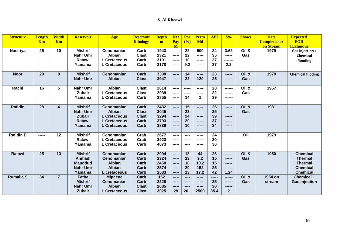
S. Al Rbeawi
Structure Length Km
Width Km
Reservoir Age Reservoir lithology
Depth m
Net Pay M
Por (%)
Perm Md
API S% Shows Date Completed or
on Stream
Expected EOR
TEchnique Nasiriya 26 10 Mishrif
Nahr Umr Ratawi
Yamama
Cenomanian Albian
L Cretaceous L Cretaceous
Carb Clast Carb Carb
1943 2321 3101 3178
----- ----- ----------
22 22 10 9.2
500 ----- ----- ----
24 35 37 37
3.62 -----
------- 2.2
Oil & Gas
1979 Gas injection + Chemical flooding
Noor 20 8 Mishrif Nahr Umr
Cenomanian Albian
Carb Clast
3308 3947
----- -----
14 22
----- 120
23 25
----- -----
Oil & Gas
1978 Chemical flloding
Rachl 16 5 Nahr UmrZubair
Yamama
Albian L Cretaceous L Cretaceous
Clast Clast Carb
2614 2938 3855
---------- -----
----- ----- 14
----- -----
1
28 32 39
------ ------ ------
Oil & Gas
1957
Rafidin 28 4 Mishrif Nahr Umr
Zubair Ratawi
Yamama
Cenomanian Albian
L Cretaceous L Cretaceous L Cretaceous
Carb Clast Clast Carb Carb
2432 3045 3294 3703 3836
----- ----- ----- ----- -----
15 23 24 20 10
----- ----- ----- ----- -----
26 25 39 37 34
----- ----- ----- ----- -----
OIl & Gas
1981
Rafidin E ----- 12 Mishrif Ratawi
Yamama
Cenomanian L Cretaceous L Cretaceous
Crab Crab Carb
2677 3923 4073
----- ----- -----
---- ---- ----
----- ----- -----
24 30 30
Oil 1979
Ratawi 25 13 Mishrif Ahmadi
Mauddud Nahr Umr Yamama
Cenomanian Cenomanian
Albian Albian
L cretaceous
Carb Carb Carb Carb Carb
2094 2324 2458 2574 2533
----- ----- ----- ----- -----
18 23 18 20 13
44 9.2 10.2 152 17.2
26 15 15 25 42
----- ----- ----- ----- 1.24
Oil & Gas
1950 Chemical Thermal Thermal Chemical Chemical
Rumaila S 34 7 Fatha Mishrif
Nahr Umr Zubair
Mipcene Cenomanian
Albian L Cretaceous
Carb Carb Clast Clast
152 2228 2685 3025
----- ----- ----- 29
---- ---- ---- 20
----- ----- -----
2500
----- 25 30
35.4
------ ------ -----
2
OIl & Gas
1954 on stream
Chemical + Gas injection
67