Embed Size (px)
Citation preview
METZ CONNECT GmbH | Im Tal 2 | 78176 Blumberg | GermanyPhone +49 7702 533-0 | Fax +49 7702 533-433Mounting instruction see www.metz-connect.com
2. Declaration of Conformity The device was tested according to the applicable standards. Confor-mity was proofed. The declaration of conformity is available at the manufacturer METZ CONNECT GmbH.
Notes Regarding Device DescriptionThese instructions include indications for use and mounting of the device. In case of questions that cannot be answered with these in-structions please consult supplier or manufacturer. The indicated installation directions or rules are applicable to the Federal Republic of Germany. If the device is used in other countries it applies to the equipment installer or the user to meet the national directions.
Safety InstructionsKeep the applicable directions for industrial safety and prevention of accidents as well as the VDE rules. Technicians and/or installers are informed that they have to electrically discharge themselves as prescribed before installation or maintenance of the devices.Only qualified personnel shall do mounting and installation work with the devices, see section “qualified personnel”. The information of these instructions have to be read and understood by every person using this device.
SymbolsWarning of dangerous electrical voltage Danger
means that non-observance may cause risk of life, grievous bodily harm or heavy material damage.
Qualified PersonnelQualified personnel in the sense of these instructions are persons who are well versed in the use and installation of such devices and whose professional qualification meets the requirements of their work. This includes for example: • Qualification to connect the device according to the VDE specifications and the local regulations and a qualification to put this device into operation, to power it down or to activate it by respecting the internal directions. • Knowledge of safety rules. • Knowledge about application and use of the device within the equipment system etc.
7632
/899
299-
12
Digital Input module BMT-SI411088913
1. DescriptionThe BACnet MS/TP module with 4 S0 inputs to DIN EN 62053-31 class A was developed for decentralized switching tasks. It is suitable for counting S0 counter pulses. This allows very good integration of the module into an energy controlling system. In case of a power failure, the last counter readings are saved. The inputs can be scanned by means of standard objects via a BACnet client. The module is addressed and the baud rate is set by means of two address switches on the front.Suitable for decentralized mounting in serial sub-distributor.
3. Technical DataBACnet InterfaceProtocoll BACnet MS/TPTransmission rate 9600 ... 115200 Bd (factory setting 9600 Bd)Cabling RS485 two wire bus with voltage equalizing cable in bus / line topology terminate with 120 Ohms
SupplyOperating voltage range 20 ... 28 V AC/DC (SELV)Current consumption 170 mA (AC) / 65 mA (DC)Relative duty cycle 100 %
Input4x S0 input according to DIN EN 62053-31 Class A
HousingDimensions WxHxD 1.4 x 2.8 x 3.0 in. (35 x 70 x 65 mm)Weight 83 gMounting position anyMounting standard rail TH35 per IEC 60715Mounting in series the maximum quantity of modules without space connected in line is limited to 15 or to a maximum power consumption of 2 Amps (AC or DC) per connection to the power supply. For any similar block of additional modules a sepa- rate connection to the power supply is mandatory.Material Housing polyamide 6.6 V0 Terminal blocks polyamide 6.6 V0Cover plate polycarbonateType of protection (IEC 60529) Housing IP40 Terminal blocks IP20
Terminal blocksSupply and bus 4 pole terminal block max. AWG 16 (1,5 mm²) solid wire max. AWG 18 (1,0 mm²) stranded wireWire diameter min. 0.3 mm up to max. 1.4 mm (terminal block and jumper plug are included to each packing unit)Module connection Input max. AWG 12 (4.0 mm²) solid wire max. AWG 14 (2.5 mm²) stranded wireWire diameter min. 0.3 mm up to max 2.7 mmProtective circuitry polarity reversal protection of operating voltage polarity reversal protection of supply and bus
Temperature rangeOperation 23° F to 131° F (-5 °C to +55 °C)Storage -4° F to +158° F (-20 °C to +70 °C)
DisplayOperating / bus activity green LEDError indication red LEDStatus of the inputs yellow LED
24 V AC/DC
GND
BUS B+
BUS A-
GND
B+
A-
+24V
B+
A-
S04-
+24V
GND
S04+ S03- S03+
S01+ S01- S02+ S02-
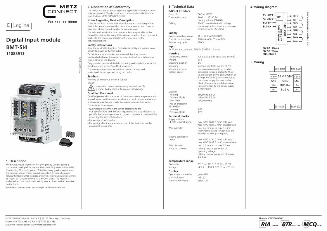
4. Wiring diagram
5. Wiring
MO
DB
us
RT
Uo
n R
S-4
85
A1/ +24V A2/ GND
BUS B +BUS A -
24V
RIS
C -
CP
U
Use
Co
pp
er C
on
du
cto
rs O
nly
24V AC / 170mA24V DC / 65mAGND, Class 2
S01+
S01
S04+
S04
S02+
S02S03+
S03
METZ CONNECT GmbH | Im Tal 2 | 78176 Blumberg | GermanyPhone +49 7702 533-0 | Fax +49 7702 533-433Mounting instruction see www.metz-connect.com
21
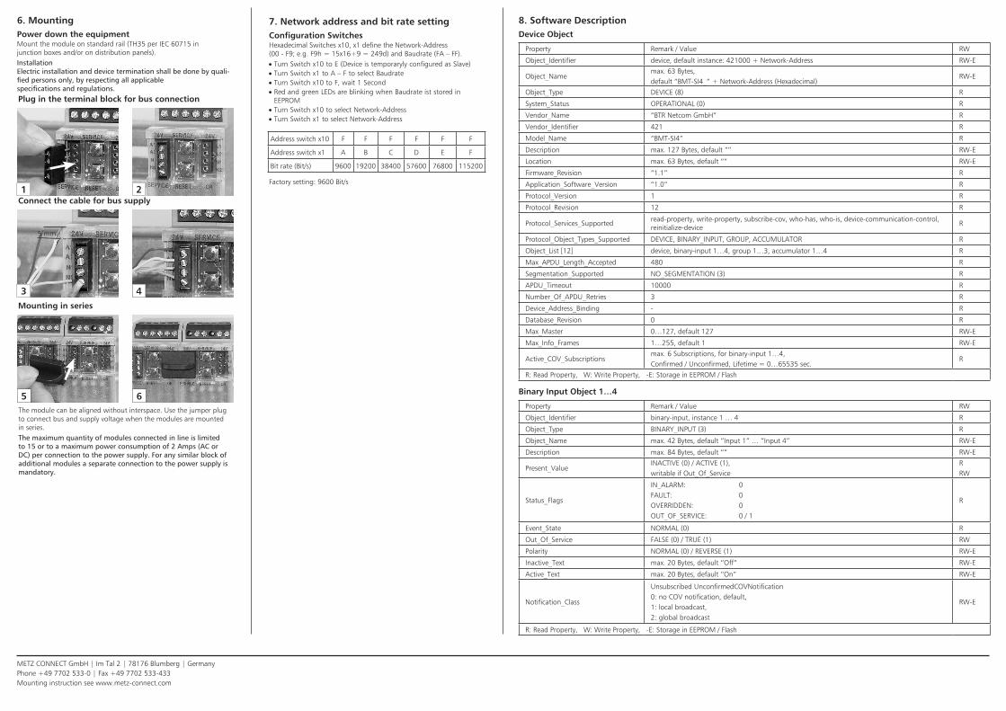
6. MountingPower down the equipmentMount the module on standard rail (TH35 per IEC 60715 in junction boxes and/or on distribution panels).InstallationElectric installation and device termination shall be done by quali-fied persons only, by respecting all applicable specifications and regulations.Plug in the terminal block for bus connection
43
5 mm
5 6The module can be aligned without interspace. Use the jumper plug to connect bus and supply voltage when the modules are mounted in series.The maximum quantity of modules connected in line is limited to 15 or to a maximum power consumption of 2 Amps (AC or DC) per connection to the power supply. For any similar block of additional modules a separate connection to the power supply is mandatory.
Connect the cable for bus supply
Mounting in series
7. Network address and bit rate settingConfiguration SwitchesHexadecimal Switches x10, x1 define the Network-Address (00 - F9; e.g. F9h = 15x16+9 = 249d) and Baudrate (FA – FF). • Turn Switch x10 to E (Device is temporaryly configured as Slave) • Turn Switch x1 to A – F to select Baudrate • Turn Switch x10 to F, wait 1 Second • Red and green LEDs are blinking when Baudrate ist stored in EEPROM • Turn Switch x10 to select Network-Address • Turn Switch x1 to select Network-Address
Factory setting: 9600 Bit/s
Address switch x10 F F F F F F
Address switch x1 A B C D E F
Bit rate (Bit/s) 9600 19200 38400 57600 76800 115200
8. Software DescriptionDevice Object
Property Remark / Value RW
Object_Identifier device, default instance: 421000 + Network-Address RW-E
Object_Namemax. 63 Bytes, default “BMT-SI4_” + Network-Address (Hexadecimal)
RW-E
Object_Type DEVICE (8) R
System_Status OPERATIONAL (0) R
Vendor_Name “BTR Netcom GmbH” R
Vendor_Identifier 421 R
Model_Name “BMT-SI4” R
Description max. 127 Bytes, default “” RW-E
Location max. 63 Bytes, default “” RW-E
Firmware_Revision “1.1” R
Application_Software_Version “1.0” R
Protocol_Version 1 R
Protocol_Revision 12 R
Protocol_Services_Supportedread-property, write-property, subscribe-cov, who-has, who-is, device-communication-control, reinitialize-device
R
Protocol_Object_Types_Supported DEVICE, BINARY_INPUT, GROUP, ACCUMULATOR R
Object_List [12] device, binary-input 1…4, group 1…3, accumulator 1…4 R
Max_APDU_Length_Accepted 480 R
Segmentation_Supported NO_SEGMENTATION (3) R
APDU_Timeout 10000 R
Number_Of_APDU_Retries 3 R
Device_Address_Binding - R
Database_Revision 0 R
Max_Master 0…127, default 127 RW-E
Max_Info_Frames 1…255, default 1 RW-E
Active_COV_Subscriptionsmax. 6 Subscriptions, for binary-input 1…4,Confirmed / Unconfirmed, Lifetime = 0…65535 sec.
R
R: Read Property, W: Write Property, -E: Storage in EEPROM / Flash
Binary Input Object 1…4
Property Remark / Value RW
Object_Identifier binary-input, instance 1 … 4 R
Object_Type BINARY_INPUT (3) R
Object_Name max. 42 Bytes, default “Input 1” … “Input 4” RW-E
Description max. 84 Bytes, default “” RW-E
Present_ValueINACTIVE (0) / ACTIVE (1),writable if Out_Of_Service
RRW
Status_Flags
IN_ALARM: 0FAULT: 0OVERRIDDEN: 0OUT_OF_SERVICE: 0 / 1
R
Event_State NORMAL (0) R
Out_Of_Service FALSE (0) / TRUE (1) RW
Polarity NORMAL (0) / REVERSE (1) RW-E
Inactive_Text max. 20 Bytes, default “Off” RW-E
Active_Text max. 20 Bytes, default “On” RW-E
Notification_Class
Unsubscribed UnconfirmedCOVNotification0: no COV notification, default,1: local broadcast,2: global broadcast
RW-E
R: Read Property, W: Write Property, -E: Storage in EEPROM / Flash
METZ CONNECT GmbH | Im Tal 2 | 78176 Blumberg | GermanyPhone +49 7702 533-0 | Fax +49 7702 533-433Mounting instruction see www.metz-connect.com
Continuation Software Description
Function Table for Binary InputOut_Of_Service Polarity Binary Input Present_Value OUT_OF_SERVICE
0 001
01
0
0 101
10
0
1 001
x 1
1 101
x 1
x: Present_Value is writable and not affected by inputs
Input pulses must have minimum High and Low times of 30ms.
Accumulator Object 1…4
Property Remark / Value RW
Object_Identifier accumulator, instance 1 … 4 R
Object_Type ACCUMULATOR (23) R
Object_Name max. 42 Bytes, default “Accumulator 1” … “Accumulator 4” RW-E
Description max. 84 Bytes, default “” RW-E
Present_Valuepulse counter of corresponding input,writable if Out_Of_Service (pulse counter remains unchanged)
R-ERW
Status_Flags
IN_ALARM: 0FAULT: 0OVERRIDDEN: 0OUT_OF_SERVICE: 0 / 1
R
Event_State NORMAL (0) R
Out_Of_Service FALSE (0) / TRUE (1) RW
Max_Pres_Value 4294967295 R
Units default no-units (95) RW-E
PrescaleMultiplier 0 … 65535, default 1Modulo-Divide 1 … 65535, default 1
RW-E
Scale Float-Scale or Integer-Scale, default 1.0 (Float) RW-E
Value_Set pulse counter is stored to Value_Set, when corresponding key is pressed, default 0 R-E
R: Read Property, W: Write Property, -E: Storage in EEPROM / Flash
Group Object 1…3
Property Remark / Value RW
Object_Identifier group, instance 1 … 3 R
Object_Type GROUP (11) R
Object_Name max. 42 Bytes, default “Group 1” … “Group 3” RW-E
Description max. 84 Bytes, default “” RW-E
Present_ValuePresent_Value of Binary Inputs, see next Table
R
List_Of_Group_Members see next Table R
R: Read Property, W: Write Property, -E: Storage in EEPROM / Flash
Members of Groups
GroupBinary Input
1 2 3 4
1 x x x x
2 x x
3 x x