Embed Size (px)
Citation preview
1
A6 Nanoparticle Reinforced Al Casting Alloys Cecilia Borgonovo, Hao Yu
Report No. 09-01
Table of contents 1. Why nanocomposites?
2. The promise of nanocomposite aluminum structural components
2.1 Mechanical properties 2.2 High-temperature properties
3. Conventional manufacturing processes
3.1 Introduction 3.2 Liquid-state techniques 3.3 Solid-state processing
4. Selected manufacturing processes
4.1 Ultrasonic cavitation based solidification 4.2 Electromagnetic stirring solidification 4.3 In-situ chemical reactions
5. Proposed approach at ACRC
5.1 Electromagnetic stirring solidification 5.2 In-situ chemical reactions
6. Bio-sketches (Hao and Cecilia)
2
1. Why Nano-Composites?
The term "Metal Matrix Nano-Composites (MMNCs)" broadly refers to a composite system which is based on metal or alloy substrate, combined with metallic or non-metallic nano-scale reinforcements. The main advantages of MMNCs include excellent mechanic performance, high working temperature, wear resistance, low creep rate and etc. MMNCs are broadly used in aerospace industry and other high technology fields. In the past years, MMNCs have been extensively studied, especially the fabrication methods. A variety of new manufacturing processes, such as semi-solid casting and spray deposition, promoted the developments of MMNCs, lowered the cost of fabrication and enabled the applications of MMNCs extended from high technology to automobile industry.
Improved Properties
Metal matrix composites (MMCs) such as continuous carbon or boron fiber reinforced aluminum and magnesium,and silicon carbide reinforced aluminum have been used for aerospace applications due to their lightweight and tailorable properties[cite]. In the past few decades, there is an increasing interest to produce Metal Matrix Nano-composite that incorporate nanoparticles for structural applications, as these materials show better performances as compared to composites with micron-sized reinforcements. For example, the tensile strength of a 1 vol.%SI3N4(10nm)-Al composite has been found to be comparable to that of a 15 vol.%SiCp(3.5µm)-Al composite, with the yield stress of the nano-metric MMC being significantly higher than that of the micro-metric MMC [1].
Low Cost Solutions
The key to realize the commercial application of MMNCs is the need to find out one effective and low cost method to produce these materials. Most of the existent fabrication routes involves the use of powder metallurgy techniques, which are not only high cost, but also result in the presence of porosity and impurity. Solidification processing methods, such as squeeze casting, stir mixing and pressure infiltration have superiority over the other processes in rapidly and low cost producing large and complex near-net shape components [2]. However, less effort has been taken in this area in the fabrication of nano-composties.
In this report, the advantages of MMNCs are explored and a variety of fabrication methods of MMNCs are introduced and compared. Solidification processing of MMNCs assisted with electromagnetic stirring and in situ method are elaborated in this report.
3
References
1. Y.C. Kang, S.L. Chan, Materials Chemistry and Physics, Vol.85, (2004), p438. 2. L.Fischer, Literature Survey Report: Nano-Dispersion Strengthening of Aluminum,
Introduction to research, 2004, University of Colorado
2. The promise of nanocomposite Al structural component
2.1 Mechanical Properties
The study of metal matrix composite dates back to the 1960s'. In the year of 1963, research on the W/Cu composite was reported, followed by the research on SiC/Al, Al2O3/Al composite [1]. In 1978, US reported the application of B/Al composite on Columbia space shuttle [2]. In 1982, Toyota [3] reported the application of Al2O3.SiO2/Al composite in the fabrication of piston, which is the first attempt to realize the civil application of metal matrix composite. After that, the research on metal matrix composite has obtained more and more interest from the scientists, a large quantity of new metal matrix composites, such as C/Cu, C/Mg, SiCw/Al composite were investigated and developed, many of which have come into commercial application in Aerospace and automobile industries.
Particle reinforced metal matrix composite offer attractive advantages, such as simple fabrication technology, low equipment requirements, in favor of mass production and relatively low cost, which enables being extensively studied in the past few years. The main matrix systems, which are being explored include Aluminim matrix, Magnesium matrix, Copper matrix, Zinc matrix and Titanium matrix, the reinforcements include SiC, Al2O3, TiC, TiB2 and B4C.
Over the past two decades aluminum matrix composites have been used in numerous structural, non-structural and functional applications of different engineering sectors. It has been proved that they can lead to high performances, and to economic and environmental benefits. The compelling need to achieve superior properties combined with top level results in weight saving, implies the massive use of these materials in transport sector and especially in diesel engines components.
Aluminum matrix composites provide outstanding mechanical properties, especially high specific strength and high specific modulus. Reinforced particles and fibers, such as carbon fibers and SiC particles, have extremely high strength and modulus. For instance, the maximum strength of carbon fiber, whose density is 1.85 g/cm3, could be 7000 MPa, which is ten times of the strength of aluminum alloys. Moreover, the modulus of graphite fibers could be as high as 900 GPa. A very small amount of added reinforcements could significantly increase the strength and modulus of Aluminum composites.
4
The reinforcements of Aluminum composite involve particle size ranging from around 10 nm up to 500 μm. Composite with a dispersion of particles in the range of 10 nm to 1 μm are termed "nano-composites". Much research has been conducted on aluminum composites, however, the majority of the work has focused on micro-metric particle dispersions which are easier to achieve than nano-sized particle distribution, but less effective in strengthening [4].
Aluminum matrix nano-composites offer significant opportunities for developing structural materials with combined physical and mechanical properties which can’t be achieved by monolithic alloys or micro-sized reinforcements. Aluminum nano-composite exhibits attractive mechanical properties, such as high yield and ultimate strength, creep and fatigue resistance. Especially, nano-composite can overcome drawbacks that cannot be avoided by micro-composite, such as low ductility.
The manner by which the SiC particles affect the tensile strength of the aluminum alloy composite can be best described in terms of increased work hardening [5].
To strengthen a material by the method of macroscopically speaking, plastic deformation (in which the nano-scopic effect increases the material's dislocation density) is defined as work hardening. More dislocations will be prevented from nucleating (which resists the dislocation development) as the material becomes saturated with new born dislocations. The strengthening then will be observed with the process of resistance effecting on plastic deformation.
The defects in the form of dislocations (which created by fluctuations in stress fields in the materials culminating in a lattice rearrangement as the dislocations propagate through the lattice) often carry out irreversible deformation on a microscopic scale in metallic crystals. Annealing does not annihilate the dislocations at normal temperature. While the dislocations accumulate, interact with each other and serve as pinning points or blocks that impede the motion as well. The result is an increase in the yield strength of the material and decrease in ductility.
Dislocations, which surrounded by strained bonds are defined as line defects in a material’s crystal structure in materials science. This is the reason why these bonds break first during plastic deformation. In terms of the thermodynamics, the crystal tends to lower their energy through bond formation between constituents of the crystal. This also explains the interaction in between the dislocations and atoms. It leads a lower but energetically favorable energy conformation of the crystal. Dislocations are just vacancies in the host medium which does exist, this feature makes them “negative-entity” in that they do not exist. As a result, the atoms or ions do not move a lot. Instead, the motion in a bonding pattern of largely stationary atoms is much greater.
Characterization of the strained bonds around a dislocation is done by lattice strain fields. As an example, in the compressive strain fields and tensile strain fields, the compressively strained bonds are directed next to an edge dislocation and strained bonds beyond (in tension) the end of an edge dislocation. It is interesting to find out that strain fields can be compared to electric fields
5
in certain ways. For example, the strain fields of dislocations follow the rule of attraction and repulsion.
As speaking of the deformation, microscopic dislocation motion results in visible plastic deformation. Work hardening can be measured by the increase in the number of dislocation. When work and energy are done on a material, plastic deformation will occur. Furthermore, large amounts of fast applied energy not only moves existing dislocation, but also produce a great number of new dislocations by jarring and working the substance sufficiently.
In a cold-worked material, the yield strength is increased. By using the lattice strain fields, the movement of dislocations is shown to be hindered by the surrounding filled with other dislocations. Once dislocation motion is hindered, plastic deformation will not be able to occur at normal stresses. When stress is applied just over the yield strength of non-cold-worked material, elastic deformation will be the only method for cold-worked material to continue to deform, with the normal scheme of stretching or compressing of electrical bond continue to occur and unchanging the elastic modulus. At last, to overcome the strain-field interactions and plastic deformation resumes, the stress should be large enough.
On the other hand, decreasing of the work-hardened material ductility will occur. Ductility is the limitation of a certain material that can perform plastic deformation, in another word, the extent of a material can be plastically deformed before fracture. While a cold-worked material has already been extended through part of its allowed plastic deformation. If dislocation accumulation hinders the dislocation motion and plastic deformation, and at the same time, stretching of electronic bonds and elastic deformation cannot be extended any more, fracture will be the third mode of deformation.
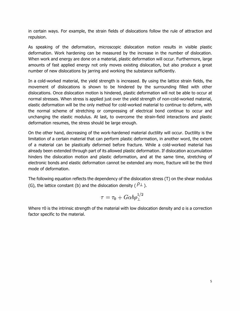
The following equation reflects the dependency of the dislocation stress (T) on the shear modulus
(G), the lattice constant (b) and the dislocation density ( ).
Where τ0 is the intrinsic strength of the material with low dislocation density and α is a correction factor specific to the material.
6
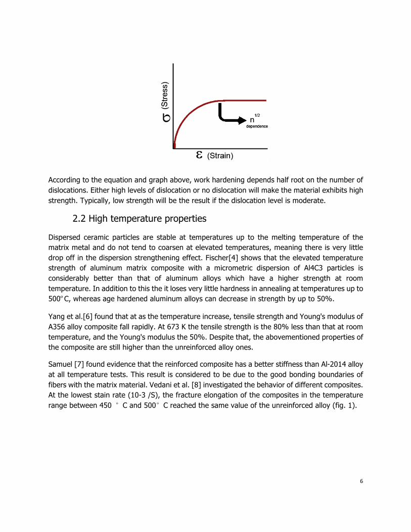
According to the equation and graph above, work hardening depends half root on the number of dislocations. Either high levels of dislocation or no dislocation will make the material exhibits high strength. Typically, low strength will be the result if the dislocation level is moderate.
2.2 High temperature properties
Dispersed ceramic particles are stable at temperatures up to the melting temperature of the matrix metal and do not tend to coarsen at elevated temperatures, meaning there is very little drop off in the dispersion strengthening effect. Fischer[4] shows that the elevated temperature strength of aluminum matrix composite with a micrometric dispersion of Al4C3 particles is considerably better than that of aluminum alloys which have a higher strength at room temperature. In addition to this the it loses very little hardness in annealing at temperatures up to 500ºC, whereas age hardened aluminum alloys can decrease in strength by up to 50%.
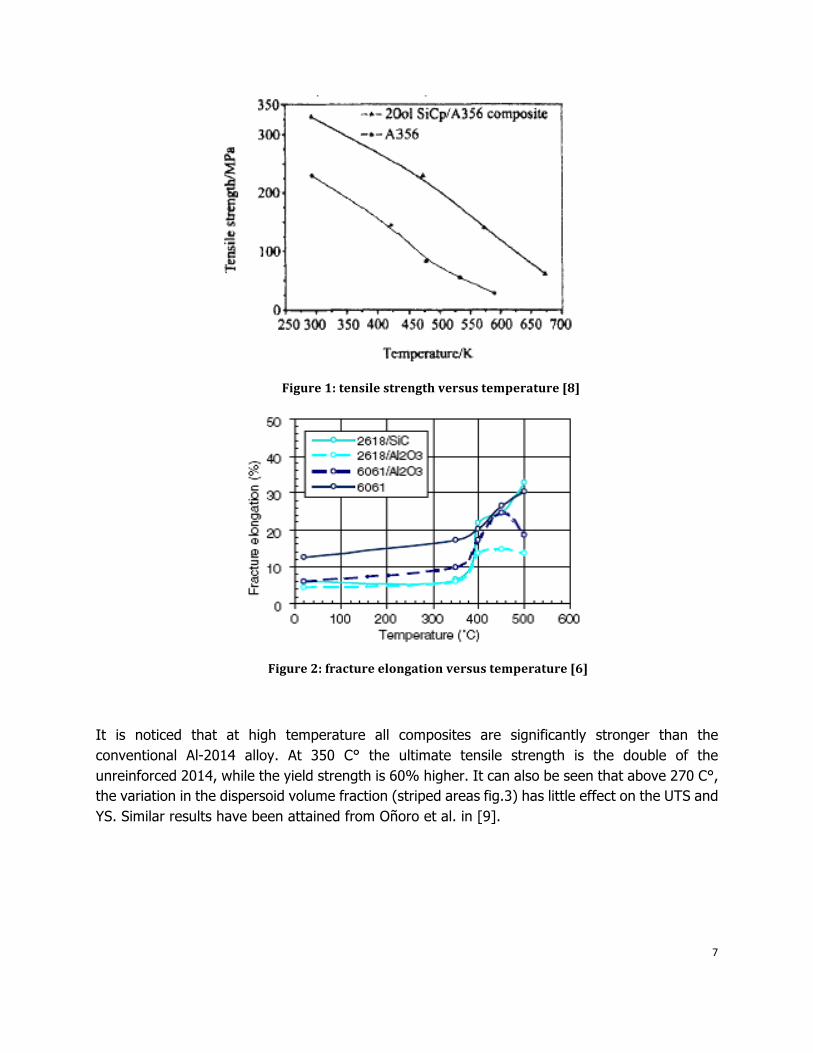
Yang et al.[6] found that at as the temperature increase, tensile strength and Young's modulus of A356 alloy composite fall rapidly. At 673 K the tensile strength is the 80% less than that at room temperature, and the Young's modulus the 50%. Despite that, the abovementioned properties of the composite are still higher than the unreinforced alloy ones.
Samuel [7] found evidence that the reinforced composite has a better stiffness than Al-2014 alloy at all temperature tests. This result is considered to be due to the good bonding boundaries of fibers with the matrix material. Vedani et al. [8] investigated the behavior of different composites. At the lowest stain rate (10-3 /S), the fracture elongation of the composites in the temperature range between 450 °C and 500°C reached the same value of the unreinforced alloy (fig. 1).
7
Figure 1: tensile strength versus temperature [8]
Figure 2: fracture elongation versus temperature [6]
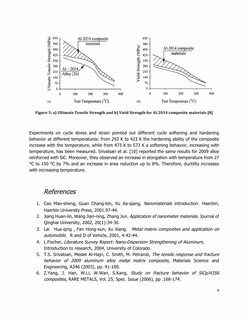
It is noticed that at high temperature all composites are significantly stronger than the conventional Al-2014 alloy. At 350 C° the ultimate tensile strength is the double of the unreinforced 2014, while the yield strength is 60% higher. It can also be seen that above 270 C°, the variation in the dispersoid volume fraction (striped areas fig.3) has little effect on the UTS and YS. Similar results have been attained from Oñoro et al. in [9].
8
Figure 3: a) Ultimate Tensile Strength and b) Yield Strength for Al2014 composite materials [8]
Experiments on cycle stress and strain pointed out different cycle softening and hardening behavior at different temperatures: from 293 K to 423 K the hardening ability of the composite increase with the temperature, while from 473 K to 573 K a softening behavior, increasing with temperature, has been measured. Srivatsan et al. [10] reported the same results for 2009 alloy reinforced with SiC. Moreover, they observed an increase in elongation with temperature from 27 °C to 150 °C by 7% and an increase in area reduction up to 8%. Therefore, ductility increases with increasing temperature.
References
1. Cao Mao-sheng, Guan Chang-bin, Xu Jia-qiang, Nanomaterials introduction.Haerbin; Haerbin University Press, 2001.97-44.
2. Jiang Huan-lin, Wang Jian-ning, Zhang Jun. Application of nanometer materials. Journal of Qinghai University, 2002, 20(1):34-36.
3. Lai Hua-qing , Fan Hong-xun, Xu Xiang. Metal matrix composites and application on automobile.R and D of Vehicle, 2001, 4:42-44.
4. L.Fischer, Literature Survey Report: Nano-Dispersion Strengthening of Aluminum, Introduction to research, 2004, University of Colorado
5. T.S. Srivatsan, Meslet Al-Hajri, C. Smith, M. Petraroli, The tensile response and fracture behavior of 2009 aluminum alloy metal matrix composite, Materials Science and Engineering, A346 (2003), pp. 91-100.
6. Z.Yang, J. Han, W.Li, W.Wan, S.Kang, Study on fracture behavior of SiCp/A356 composites, RARE METALS, Vol. 25, Spec. Issue (2006), pp .168-174.
9
7. M.Samuel, Reinforcement of recycled aluminum-alloy scrap with Saffil ceramic fibers, Journal of Materials Processing Technology 142, 2003, pp. 295–306.
8. M.Vedani, F.D‘Errico, E.Gariboldi, Mechanical and fracture behaviour of aluminium-based discontinuously reinforced composites at hot working temperatures, Composites Science and Technology 66 (2006), pp. 343–349.
9. Oñoro, Salvador, Cambronero, High-temperature mechanical properties of aluminium alloys reinforced with boron carbide particles, Materials Science and Engineering A 499, 2009, pp. 421–426.
10. T.S. Srivatsan, Meslet Al-Hajri, C. Smith, M. Petraroli, The tensile response and fracture behavior of 2009 aluminum alloy metal matrix composite, Materials Science and Engineering, A346 (2003), pp. 91-100.
3. Conventional manufacturing processes
3.1 Introduction
The fabrication and study of artificial particulate composites in the form of granular metal can be dated back in the 1960s [1]. In the last decade, the industrial application of nanoscale metal composites has consistently increased, and improvements in composite processing methods are therefore pivotal for enhancing their commercial applicability. So far, many techniques have been employed to synthesize the nano-composite materials. Some of them have been extensively applied, while others are relatively new and require further understanding. The present chapter has been devoted to underline the shortcomings of conventional manufacturing processes, which are the causes of low-quality products or commercial unfeasibility. This analysis has been pursued in order to exclude some of these routes from our investigation, and in the same time to select the processes that are most promising and that will be optimized and modeled in our studies (see Chapter 5).
3.2 Liquid state techniques
Liquid metal is generally less expensive and easier to handle than powders, and the shape flexibility constitutes a significant advantage. Liquid state processes are generally fast often easy to be scaled-up. Despite this, they are affected by the lack of wettability of the reinforcement and by interfacial reactivity. Moreover, they are often limited to low-melting point metals. Liquid state routes can be sorted into three major categories [2,3,4]:
• Infiltration techniques • Agitation techniques
10
• Spraying
Infiltration techniques
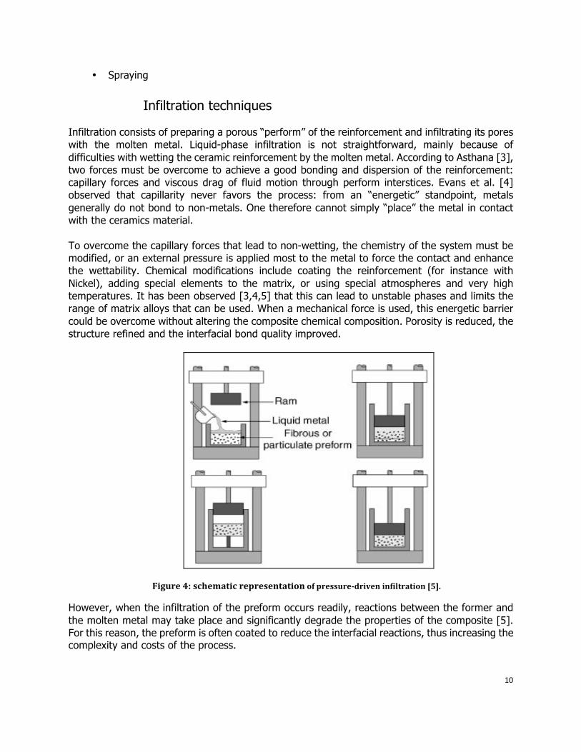
Infiltration consists of preparing a porous “perform” of the reinforcement and infiltrating its pores with the molten metal. Liquid-phase infiltration is not straightforward, mainly because of difficulties with wetting the ceramic reinforcement by the molten metal. According to Asthana [3], two forces must be overcome to achieve a good bonding and dispersion of the reinforcement: capillary forces and viscous drag of fluid motion through perform interstices. Evans et al. [4] observed that capillarity never favors the process: from an “energetic” standpoint, metals generally do not bond to non-metals. One therefore cannot simply “place” the metal in contact with the ceramics material. To overcome the capillary forces that lead to non-wetting, the chemistry of the system must be modified, or an external pressure is applied most to the metal to force the contact and enhance the wettability. Chemical modifications include coating the reinforcement (for instance with Nickel), adding special elements to the matrix, or using special atmospheres and very high temperatures. It has been observed [3,4,5] that this can lead to unstable phases and limits the range of matrix alloys that can be used. When a mechanical force is used, this energetic barrier could be overcome without altering the composite chemical composition. Porosity is reduced, the structure refined and the interfacial bond quality improved.
Figure 4: schematic representation of pressuredriven infiltration [5].
However, when the infiltration of the preform occurs readily, reactions between the former and the molten metal may take place and significantly degrade the properties of the composite [5]. For this reason, the preform is often coated to reduce the interfacial reactions, thus increasing the complexity and costs of the process.
11
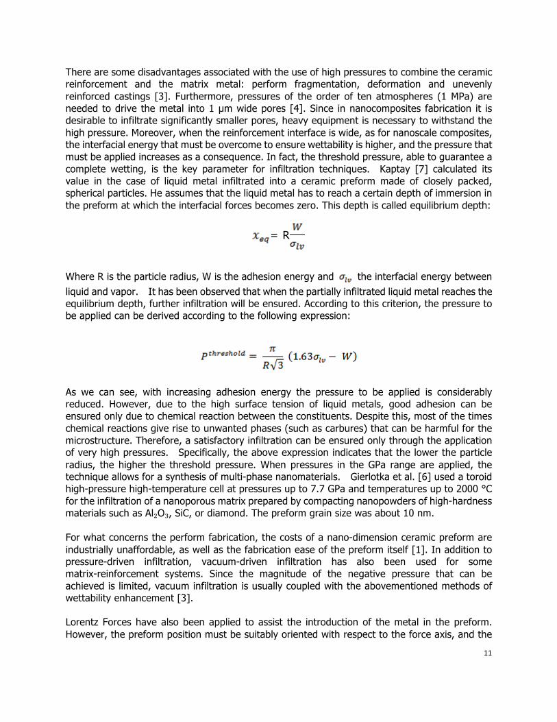
There are some disadvantages associated with the use of high pressures to combine the ceramic reinforcement and the matrix metal: perform fragmentation, deformation and unevenly reinforced castings [3]. Furthermore, pressures of the order of ten atmospheres (1 MPa) are needed to drive the metal into 1 µm wide pores [4]. Since in nanocomposites fabrication it is desirable to infiltrate significantly smaller pores, heavy equipment is necessary to withstand the high pressure. Moreover, when the reinforcement interface is wide, as for nanoscale composites, the interfacial energy that must be overcome to ensure wettability is higher, and the pressure that must be applied increases as a consequence. In fact, the threshold pressure, able to guarantee a complete wetting, is the key parameter for infiltration techniques. Kaptay [7] calculated its value in the case of liquid metal infiltrated into a ceramic preform made of closely packed, spherical particles. He assumes that the liquid metal has to reach a certain depth of immersion in the preform at which the interfacial forces becomes zero. This depth is called equilibrium depth:
= R
Where R is the particle radius, W is the adhesion energy and the interfacial energy between liquid and vapor. It has been observed that when the partially infiltrated liquid metal reaches the equilibrium depth, further infiltration will be ensured. According to this criterion, the pressure to be applied can be derived according to the following expression:
As we can see, with increasing adhesion energy the pressure to be applied is considerably reduced. However, due to the high surface tension of liquid metals, good adhesion can be ensured only due to chemical reaction between the constituents. Despite this, most of the times chemical reactions give rise to unwanted phases (such as carbures) that can be harmful for the microstructure. Therefore, a satisfactory infiltration can be ensured only through the application of very high pressures. Specifically, the above expression indicates that the lower the particle radius, the higher the threshold pressure. When pressures in the GPa range are applied, the technique allows for a synthesis of multi-phase nanomaterials. Gierlotka et al. [6] used a toroid high-pressure high-temperature cell at pressures up to 7.7 GPa and temperatures up to 2000 °C for the infiltration of a nanoporous matrix prepared by compacting nanopowders of high-hardness materials such as Al₂O₃, SiC, or diamond. The preform grain size was about 10 nm. For what concerns the perform fabrication, the costs of a nano-dimension ceramic preform are industrially unaffordable, as well as the fabrication ease of the preform itself [1]. In addition to pressure-driven infiltration, vacuum-driven infiltration has also been used for some matrix-reinforcement systems. Since the magnitude of the negative pressure that can be achieved is limited, vacuum infiltration is usually coupled with the abovementioned methods of wettability enhancement [3]. Lorentz Forces have also been applied to assist the introduction of the metal in the preform. However, the preform position must be suitably oriented with respect to the force axis, and the
12
frequency of the current, which induces the electromagnetic force is effective only within a very narrow range of values [3].
Agitation techniques
Stir mixing techniques, widely utilized to mix micron size particles in metallic melts, have been recently modified for dispersing small volume percentages of nanosized reinforcement particles in metallic matrices. Their main advantage is the capability over other processes in rapidly and inexpensively producing large and complex near-net shape components, but there are difficulties in mixing nanosized particles in metallic melts that can’t be overcome with the traditional stirring methods. Agglomerates of particles are usually observed in the solidified microstructure. This is due to the increase in surface area connected with the reduction of particle size, which enhances the difficulty of particle introduction and homogeneous dispersion through the melt. The restraints of mixing techniques when dealing with nanoscale reinforcement will be illustrated in the present paragraph.
Restraints of agitation techniques
Mixing techniques must face three main process difficulties:
1. Introduction of spherical, ceramic particles into liquid metals; 2. Avoiding coagulation of particles in the liquid metallic phase; 3. Ensuring engulfment (avoiding pushing) of ceramic particles by the
approaching solidification front. The physics of particle engulfment lays at the basis of a homogeneous particle dispersion and absence of particle agglomerates in the metal. The analysis will underline the influence of particle radius on the phenomenon.
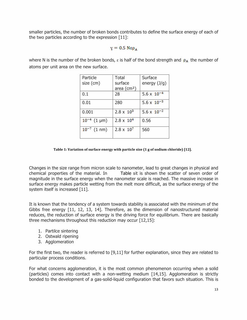
The dynamics of agglomeration The poor wetting between reinforcement material and the metal matrix presents a barrier to the incorporation of the dispersoid phase into the melt. The immersion of solids into liquids requires substitution of a solid-gas interface by an equivalent solid-liquid interface, and can lead to absorption or generation of energy [11,12]. The energetic of solid immersion into liquids are determined by the energy associated with the solid-gas interface, liquid gas interface and solid-liquid interface. By definition, the surface energy ɣ is “the energy required to create a unit area of new surface”, and represent the extra energy possessed by the surface atoms due to the decrease in bond length between the surface atoms and interior atoms [8,11,12]. When a particle is split into two
13
smaller particles, the number of broken bonds contributes to define the surface energy of each of the two particles according to the expression [11]:
where N is the number of the broken bonds, ε is half of the bond strength and the number of atoms per unit area on the new surface.
Particle size (cm)
Total surface area (cm²)
Surface energy (J/g)
0.1 28 5.6 x
0.01 280 5.6 x
0.001 2.8 x 5.6 x
(1 µm) 2.8 x 0.56
(1 nm) 2.8 x 560
Table 1: Variation of surface energy with particle size (1 g of sodium chloride) [12].
Changes in the size range from micron scale to nanometer, lead to great changes in physical and chemical properties of the material. In Table 1it is shown the scatter of seven order of magnitude in the surface energy when the nanometer scale is reached. The massive increase in surface energy makes particle wetting from the melt more difficult, as the surface energy of the system itself is increased [11].
It is known that the tendency of a system towards stability is associated with the minimum of the Gibbs free energy [11, 12, 13, 14]. Therefore, as the dimension of nanostructured material reduces, the reduction of surface energy is the driving force for equilibrium. There are basically three mechanisms throughout this reduction may occur [12,15]:
1. Partilce sintering 2. Ostwald ripening 3. Agglomeration
For the first two, the reader is referred to [9,11] for further explanation, since they are related to particular process conditions. For what concerns agglomeration, it is the most common phenomenon occurring when a solid (particles) comes into contact with a non-wetting medium [14,15]. Agglomeration is strictly bonded to the development of a gas-solid-liquid configuration that favors such situation. This is
14
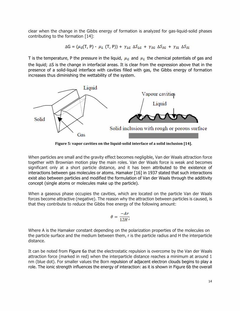
clear when the change in the Gibbs energy of formation is analyzed for gas-liquid-solid phases contributing to the formation [14]:
∆G = ( (T, P) - (T, P)) + ∆ + ∆ + ∆
T is the temperature, P the pressure in the liquid, and the chemical potentials of gas and the liquid; ∆S is the change in interfacial areas. It is clear from the expression above that in the presence of a solid-liquid interface with cavities filled with gas, the Gibbs energy of formation increases thus diminishing the wettability of the system.
Figure 5: vapor cavities on the liquidsolid interface of a solid inclusion [14].
When particles are small and the gravity effect becomes negligible, Van der Waals attraction force together with Brownian motion play the main roles. Van der Waals force is weak and becomes significant only at a short particle distance, and it has been attributed to the existence of interactions between gas molecules or atoms. Hamaker [16] in 1937 stated that such interactions exist also between particles and modified the formulation of Van der Waals through the additivity concept (single atoms or molecules make up the particle). When a gaseous phase occupies the cavities, which are located on the particle Van der Waals forces become attractive (negative). The reason why the attraction between particles is caused, is that they contribute to reduce the Gibbs free energy of the following amount:
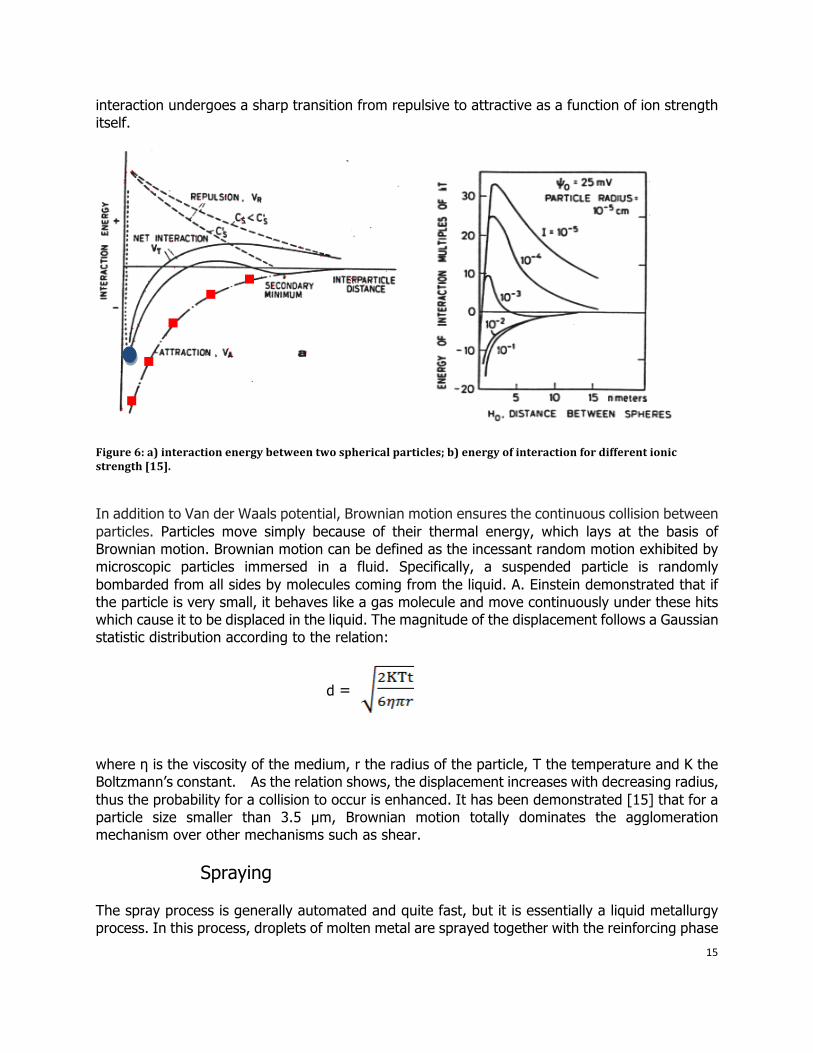
Where A is the Hamaker constant depending on the polarization properties of the molecules on the particle surface and the medium between them, r is the particle radius and H the interparticle distance. It can be noted from Figure 6a that the electrostatic repulsion is overcome by the Van der Waals attraction force (marked in red) when the interparticle distance reaches a minimum at around 1 nm (blue dot). For smaller values the Born repulsion of adjacent electron clouds begins to play a role. The ionic strength influences the energy of interaction: as it is shown in Figure 6b the overall
15
interaction undergoes a sharp transition from repulsive to attractive as a function of ion strength itself.
Figure 6: a) interaction energy between two spherical particles; b) energy of interaction for different ionic strength [15].
In addition to Van der Waals potential, Brownian motion ensures the continuous collision between particles. Particles move simply because of their thermal energy, which lays at the basis of Brownian motion. Brownian motion can be defined as the incessant random motion exhibited by microscopic particles immersed in a fluid. Specifically, a suspended particle is randomly bombarded from all sides by molecules coming from the liquid. A. Einstein demonstrated that if the particle is very small, it behaves like a gas molecule and move continuously under these hits which cause it to be displaced in the liquid. The magnitude of the displacement follows a Gaussian statistic distribution according to the relation:
d =
where η is the viscosity of the medium, r the radius of the particle, T the temperature and K the Boltzmann’s constant. As the relation shows, the displacement increases with decreasing radius, thus the probability for a collision to occur is enhanced. It has been demonstrated [15] that for a particle size smaller than 3.5 µm, Brownian motion totally dominates the agglomeration mechanism over other mechanisms such as shear.
Spraying
The spray process is generally automated and quite fast, but it is essentially a liquid metallurgy process. In this process, droplets of molten metal are sprayed together with the reinforcing phase
16
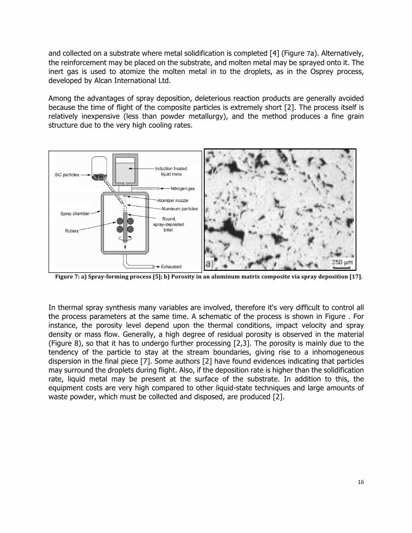
and collected on a substrate where metal solidification is completed [4] (Figure 7a). Alternatively, the reinforcement may be placed on the substrate, and molten metal may be sprayed onto it. The inert gas is used to atomize the molten metal in to the droplets, as in the Osprey process, developed by Alcan International Ltd. Among the advantages of spray deposition, deleterious reaction products are generally avoided because the time of flight of the composite particles is extremely short [2]. The process itself is relatively inexpensive (less than powder metallurgy), and the method produces a fine grain structure due to the very high cooling rates.
Figure 7: a) Sprayforming process [5]; b) Porosity in an aluminum matrix composite via spray deposition [17].
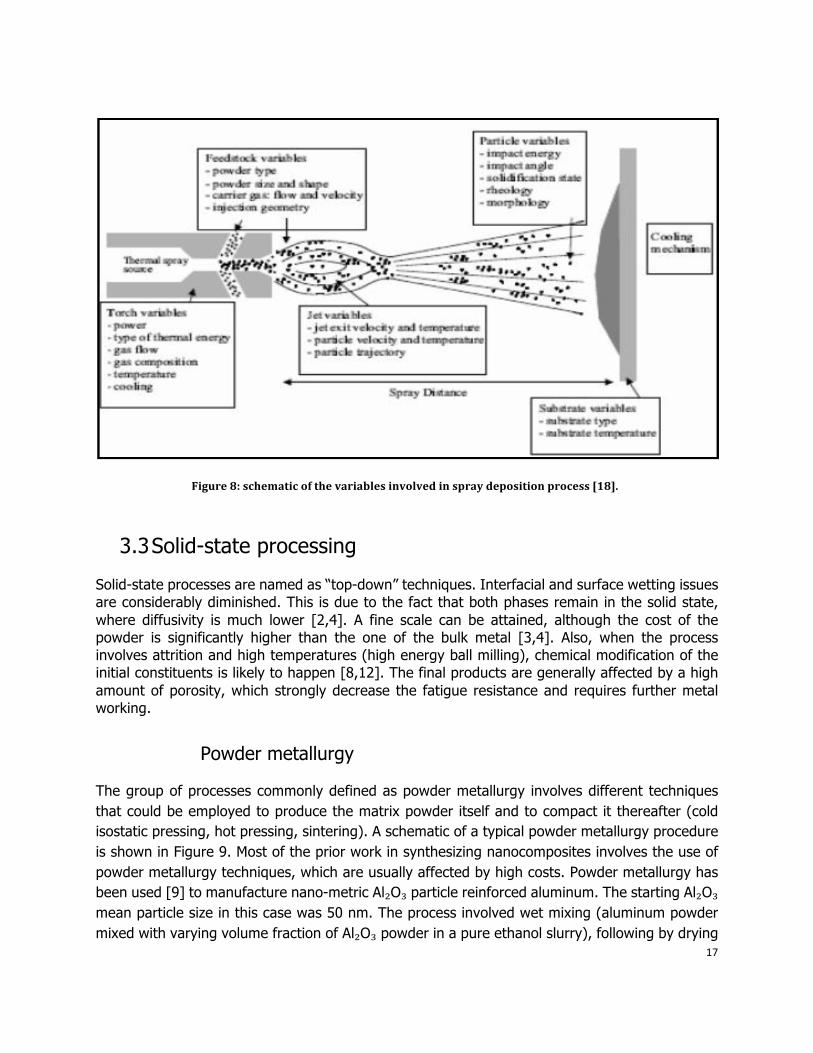
In thermal spray synthesis many variables are involved, therefore it‘s very difficult to control all the process parameters at the same time. A schematic of the process is shown in Figure . For instance, the porosity level depend upon the thermal conditions, impact velocity and spray density or mass flow. Generally, a high degree of residual porosity is observed in the material (Figure 8), so that it has to undergo further processing [2,3]. The porosity is mainly due to the tendency of the particle to stay at the stream boundaries, giving rise to a inhomogeneous dispersion in the final piece [7]. Some authors [2] have found evidences indicating that particles may surround the droplets during flight. Also, if the deposition rate is higher than the solidification rate, liquid metal may be present at the surface of the substrate. In addition to this, the equipment costs are very high compared to other liquid-state techniques and large amounts of waste powder, which must be collected and disposed, are produced [2].
17
Figure 8: schematic of the variables involved in spray deposition process [18].
3.3 Solid-state processing
Solid-state processes are named as “top-down” techniques. Interfacial and surface wetting issues are considerably diminished. This is due to the fact that both phases remain in the solid state, where diffusivity is much lower [2,4]. A fine scale can be attained, although the cost of the powder is significantly higher than the one of the bulk metal [3,4]. Also, when the process involves attrition and high temperatures (high energy ball milling), chemical modification of the initial constituents is likely to happen [8,12]. The final products are generally affected by a high amount of porosity, which strongly decrease the fatigue resistance and requires further metal working.
Powder metallurgy
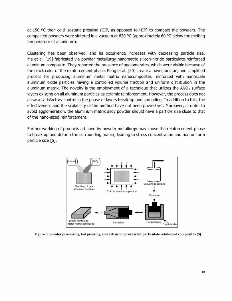
The group of processes commonly defined as powder metallurgy involves different techniques that could be employed to produce the matrix powder itself and to compact it thereafter (cold isostatic pressing, hot pressing, sintering). A schematic of a typical powder metallurgy procedure is shown in Figure 9. Most of the prior work in synthesizing nanocomposites involves the use of powder metallurgy techniques, which are usually affected by high costs. Powder metallurgy has been used [9] to manufacture nano-metric Al₂O₃ particle reinforced aluminum. The starting Al₂O₃ mean particle size in this case was 50 nm. The process involved wet mixing (aluminum powder mixed with varying volume fraction of Al₂O₃ powder in a pure ethanol slurry), following by drying
18
at 150 ºC then cold isostatic pressing (CIP, as opposed to HIP) to compact the powders. The compacted powders were sintered in a vacuum at 620 ºC (approximately 60 ºC below the melting temperature of aluminum). Clustering has been observed, and its occurrence increases with decreasing particle size. Ma et al. [19] fabricated via powder metallurgy nanometric silicon-nitride particulate-reinforced aluminum composite. They reported the presence of agglomerates, which were visible because of the black color of the reinforcement phase. Peng et al. [20] create a novel, unique, and simplified process for producing aluminum metal matrix nanocomposites reinforced with nanoscale aluminum oxide particles having a controlled volume fraction and uniform distribution in the aluminum matrix. The novelty is the employment of a technique that utilizes the Al₂O₃ surface layers existing on all aluminum particles as ceramic reinforcement. However, the process does not allow a satisfactory control in the phase of layers break-up and spreading. In addition to this, the effectiveness and the scalability of the method have not been proved yet. Moreover, in order to avoid agglomeration, the aluminum matrix alloy powder should have a particle size close to that of the nano-sized reinforcement. Further working of products attained by powder metallurgy may cause the reinforcement phase to break up and deform the surrounding matrix, leading to stress concentration and non uniform particle size [5].
Figure 9: powder processing, hot pressing, and extrusion process for particulate reinforced composites [5].
19
Mechanical attrition and alloying
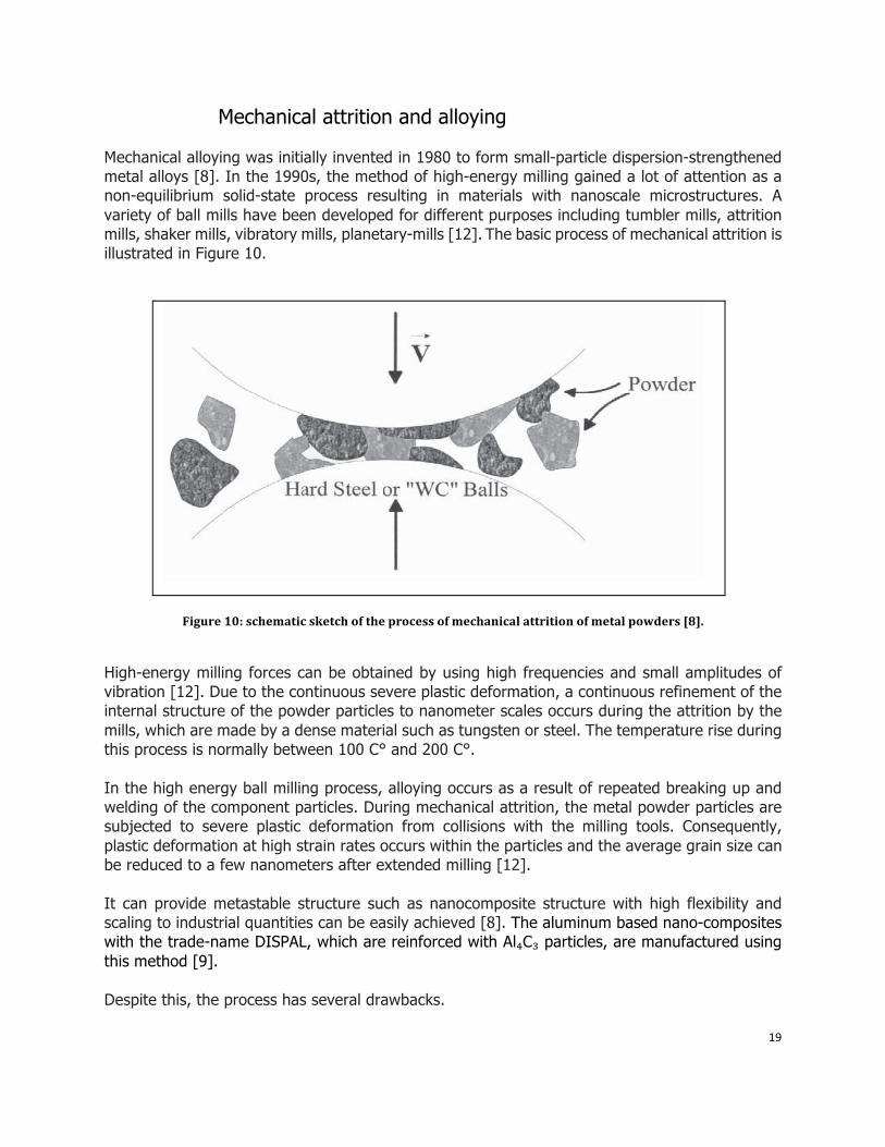
Mechanical alloying was initially invented in 1980 to form small-particle dispersion-strengthened metal alloys [8]. In the 1990s, the method of high-energy milling gained a lot of attention as a non-equilibrium solid-state process resulting in materials with nanoscale microstructures. A variety of ball mills have been developed for different purposes including tumbler mills, attrition mills, shaker mills, vibratory mills, planetary-mills [12]. The basic process of mechanical attrition is illustrated in Figure 10.
Figure 10: schematic sketch of the process of mechanical attrition of metal powders [8].
High-energy milling forces can be obtained by using high frequencies and small amplitudes of vibration [12]. Due to the continuous severe plastic deformation, a continuous refinement of the internal structure of the powder particles to nanometer scales occurs during the attrition by the mills, which are made by a dense material such as tungsten or steel. The temperature rise during this process is normally between 100 C° and 200 C°. In the high energy ball milling process, alloying occurs as a result of repeated breaking up and welding of the component particles. During mechanical attrition, the metal powder particles are subjected to severe plastic deformation from collisions with the milling tools. Consequently, plastic deformation at high strain rates occurs within the particles and the average grain size can be reduced to a few nanometers after extended milling [12]. It can provide metastable structure such as nanocomposite structure with high flexibility and scaling to industrial quantities can be easily achieved [8]. The aluminum based nano-composites with the trade-name DISPAL, which are reinforced with Al₄C₃ particles, are manufactured using this method [9]. Despite this, the process has several drawbacks.
20
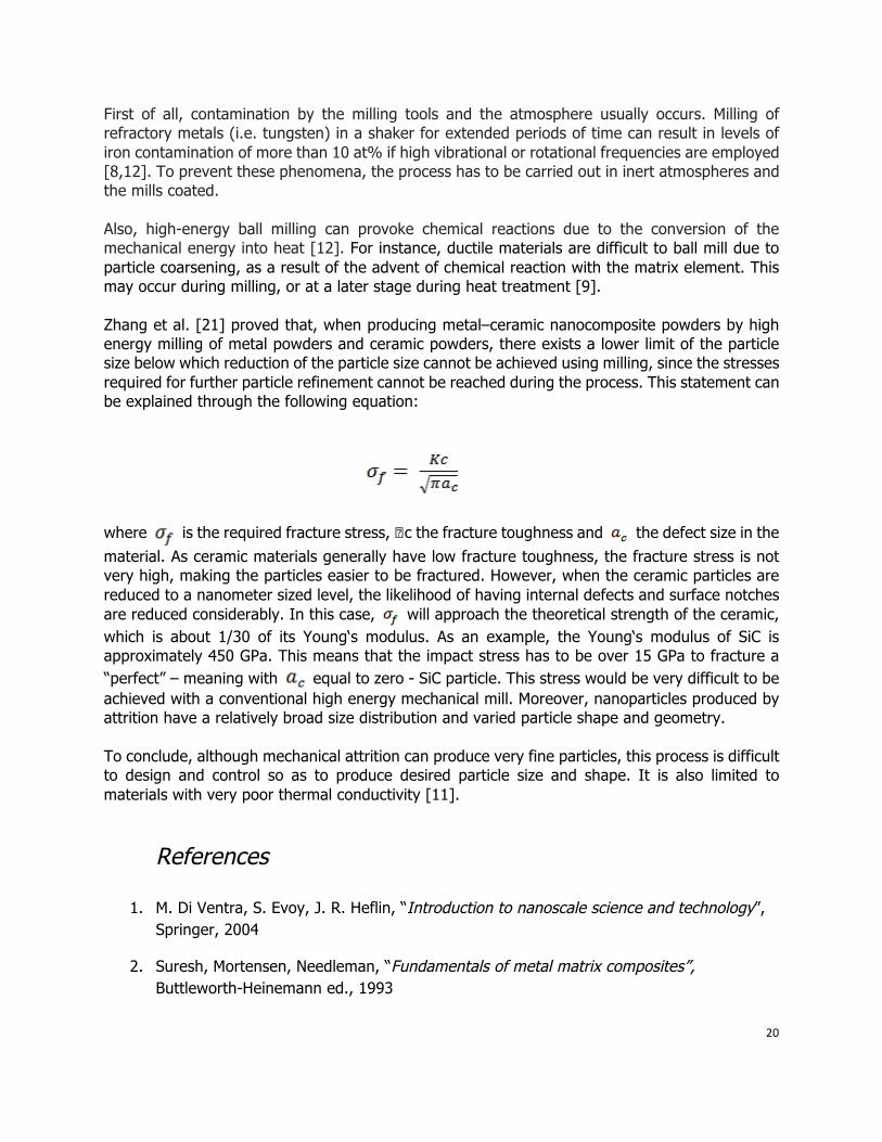
First of all, contamination by the milling tools and the atmosphere usually occurs. Milling of refractory metals (i.e. tungsten) in a shaker for extended periods of time can result in levels of iron contamination of more than 10 at% if high vibrational or rotational frequencies are employed [8,12]. To prevent these phenomena, the process has to be carried out in inert atmospheres and the mills coated. Also, high-energy ball milling can provoke chemical reactions due to the conversion of the mechanical energy into heat [12]. For instance, ductile materials are difficult to ball mill due to particle coarsening, as a result of the advent of chemical reaction with the matrix element. This may occur during milling, or at a later stage during heat treatment [9]. Zhang et al. [21] proved that, when producing metal–ceramic nanocomposite powders by high energy milling of metal powders and ceramic powders, there exists a lower limit of the particle size below which reduction of the particle size cannot be achieved using milling, since the stresses required for further particle refinement cannot be reached during the process. This statement can be explained through the following equation:
where is the required fracture stress, �c the fracture toughness and the defect size in the material. As ceramic materials generally have low fracture toughness, the fracture stress is not very high, making the particles easier to be fractured. However, when the ceramic particles are reduced to a nanometer sized level, the likelihood of having internal defects and surface notches are reduced considerably. In this case, will approach the theoretical strength of the ceramic, which is about 1/30 of its Young‘s modulus. As an example, the Young‘s modulus of SiC is approximately 450 GPa. This means that the impact stress has to be over 15 GPa to fracture a “perfect” – meaning with equal to zero - SiC particle. This stress would be very difficult to be achieved with a conventional high energy mechanical mill. Moreover, nanoparticles produced by attrition have a relatively broad size distribution and varied particle shape and geometry. To conclude, although mechanical attrition can produce very fine particles, this process is difficult to design and control so as to produce desired particle size and shape. It is also limited to materials with very poor thermal conductivity [11].
References
1. M. Di Ventra, S. Evoy, J. R. Heflin, “Introduction to nanoscale science and technology”, Springer, 2004
2. Suresh, Mortensen, Needleman, “Fundamentals of metal matrix composites”, Buttleworth-Heinemann ed., 1993
21
3. R. Ashtana, “Solidification Processing of Reinforced Metals”, Trans. Tech Publications, 1997
4. A. Evans, C. San Marchi, A. Mortensen, “Metal Matrix Composites in Industry: An Introduction and a Survey”, Springer, 2003
5. Krishan Kumar Chawla, “Metal matrix composites”, Birkhäuser, 2006
6. Gierlotka, Synthesis of Metal-Ceramic Nanocomposites by high pressure infiltration, Science24.com
7. G.Kaptay, “Interfacial criteria for producing ceramic reinforced metal-matrix composites”, Proc. Int. Conf. High Temperature Capillarity 29 June-2 July 1997, Poland
8. P. M. Ajayan, L. S. Schadler, P. V. Braun, “Nanocomposite science and technology”, Wiley-VCH, 2003
9. L.Fischer,” Literature Survey Report: Nano-Dispersion Strengthening of Aluminum”, Introduction to research, 2004, University of Colorado
10. Vozken Adrian Parsegian, “Van der Waals forces: a handbook for biologists, chemists, engineers, and physicists”, Cambridge University Press, 2006
11. Guozhong Cao, “Nanostructures & nanomaterials: synthesis, properties & applications”, Imperial College Press, 2004
12. C. C. Koch, “Nanostructured materials: processing, properties, and applications”, William Andrew, 2006
13. Fast, “Interaction of Metals and Gases”, Academic Press, 1965.
14. M. Cournil, F.Gruy, P. Cugniet, P. Gardina, H. Saint-Raymond, “Model of aggregation of solid particles in nonwetting liquid medium”, Centre SPIN, URA CNRS 2021, Ecole Nationale Supérieure des Mines de Saint-Etienne.
15. “Particle collision and aggregation”, Oceanography 540--Marine Geological Processes--Autumn Quarter 2002
16. Rhonda Lee-Desautels, “Theory of van der Waals Forces as Applied to Particlate Materials”, Educ. Reso. for Part. Techn. 051Q-Lee
17. Thomas Seefeld, Emil Schubert and Gerd Sepold,” Spray Deposition of MMC Composites by Laser Spraying with Particle Co-injection”, BIAS Bremen Institute of Applied Beam Technology
18. B.Onur, Nanocomposites. 19. Z.Y. Ma, Y.L. Lia, Y. Liang, L F. Zheng , J. BP, S.C. Tjong, “Nanometric Si3N 4
particulate-reinforced aluminum composite”, Materials Science and Engineering A219, 1996, pp. 229-231
22
20. Peng et al., “Manufacturing method for aluminum matrix nanocomposites”, United States Patent, 7297310
21. D.L. Zhang, J. Liang, J. Wu, “Processing Ti3Al–SiC nanocomposites using high energy mechanical milling”, Materials Science and Engineering A 375–377 , 2004, pp. 911–916
4. Selected Manufacturing Processes
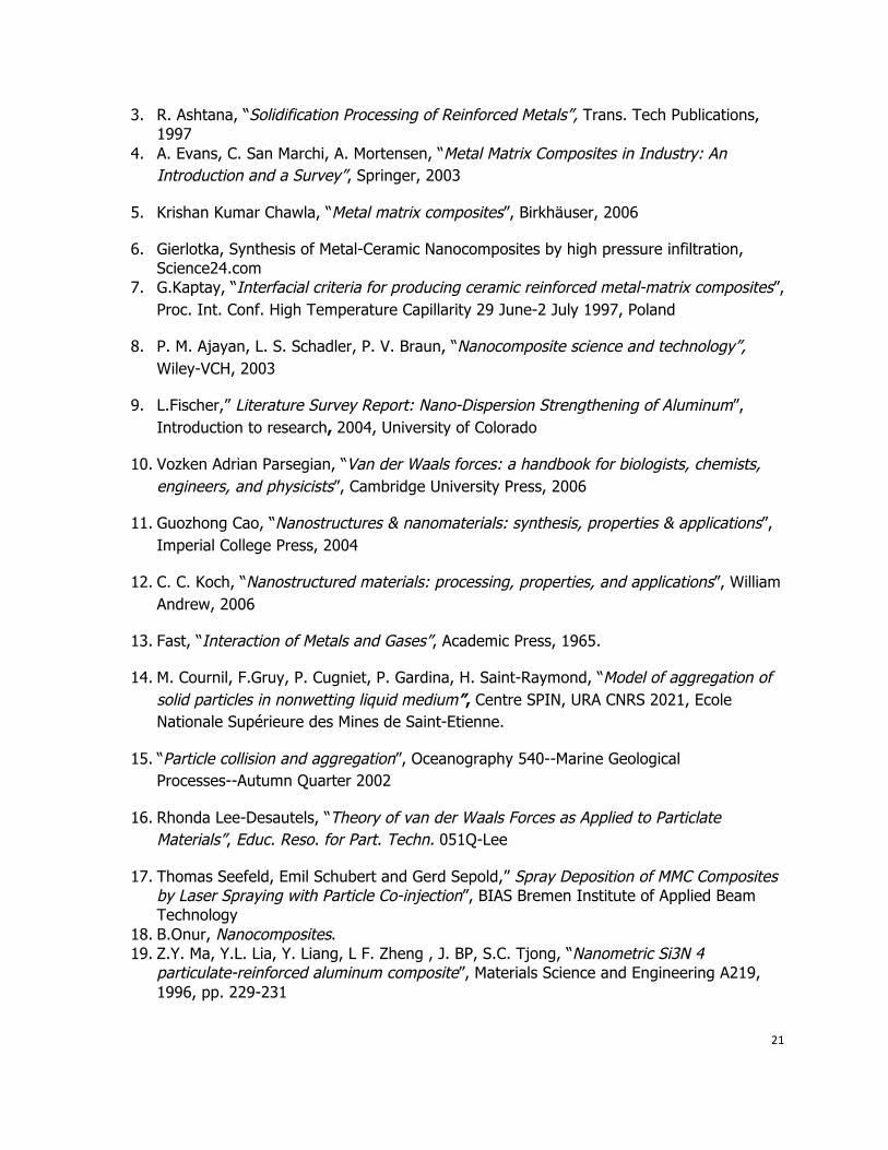
4.1 Ultrasonic Cavitation Based Solidification High-intensity ultrasonic waves (above 25 W/cm²) can generate strong non-linear effects in the liquid such as transient cavitation and acoustic streaming (a liquid melt flow due to an acoustic pressure gradient) [1]. They are mostly responsible for dispersive effect for homogenizing, degassing for reduced porosity and refining microstructure [2].
Experimental parameters and design of experiment
As it is shown in Figure 11, the A356 alloy is melted in a graphite crucible (2 lb. capacity) using an electric resistance heating unit and protected by Argon gas. The ultrasonic probe (Permendur probe) is made of Niobium (Nb) which can withstand high processing temperature with minimum ultrasonic cavitation induced erosion [1].
An alternative arrangement [3] consists in ultrasonic transducers arrayed outside, and coupled with the crucible.
Figure 11: Schematic of experimental setup [1].
23
Nano-sized particles (β-SiC with average size <= 30 nm) are added into the melt during the process by manual handling and mechanical delivery. Yang and Li observed in their study [2] the tendency of particles to float on the surface of the melt when added, due to the poor wettability and to the high surface tension of the melt. Therefore, a more effective feeding method was demanded. In their work [1] they tried two different feeding techniques: master powder carrying method and compressed inert gas spraying method; indeed, large micro-clusters were formed.
The processing temperature was controlled between 50 C° and 100 C° above the alloy melting point (610 C°) [4], but after ultrasonic process a higher melt temperature (780 C°) was kept in order to ensure flowability (this avoids too high solid fraction). As observed during the processing, the viscosity of the melt significantly increased [2].
Li and Yang [4] optimized the process parameter through Design Of Experiment. They did trials with different ultrasonic powers ( 2.5 kW, 3.0 kW,4.0 kW) and temperature (650 C°, 700 C°, 760 C°); while time and nanoparticles weight percentage were kept constant (60 minutes and 1.0% particles). In a previous work [2] various weight percentages of SiC (1.0 wt.%, 1.5 wt.%, 2.0 wt.%) were added to the melt, in order to investigate the effect on mechanical properties.
Mechanical properties
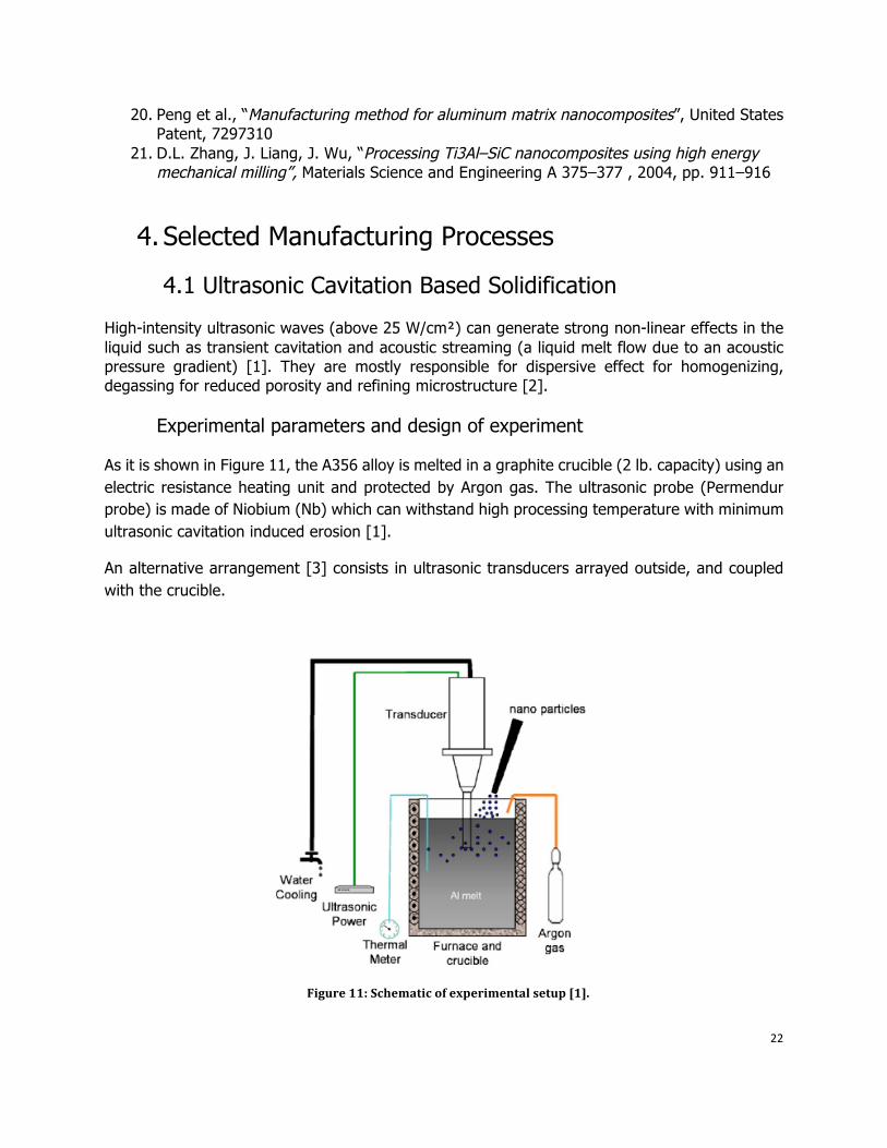
It has been found [1] that with a 3.5 kW ultrasonic power, the ultimate tensile strength and yield strength were improved respectively more than 60% and 100% respectively with only 1.0 wt.% and 1.5 wt. % of nanoparticles. However, with 2 wt % SiC, the strengths decrease (fig.12), very likely beause of the creation of microclusters, which increases with weight percentage of particles.
Figure 12: strengths increment versus SiC wt.% [1].
24
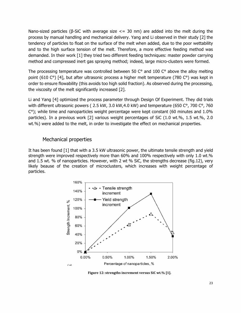
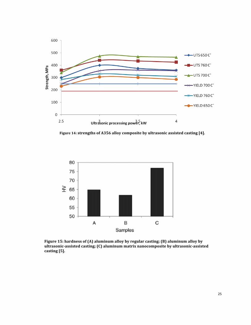
The great advantage reported [2] is the retained ductility (fig.13), due to the enhanced wettability and the high density dislocation. In the study [4], Yang and Li measured the best ultimate and yield strength for a processing temperature of 700 C° and 3.0 kW ultrasonic power, and the same for elongation (fig. 14). The experiment was pursued with 1.0 wt.% of SiC nanoparticles, and the mechanical properties improved near 100% with these optimized values.
According to Orowan mechanism, a more uniform overall distribution causes a decrease in interparticle spacing (<100 nm), that leads to a restricted dislocation movement, and thus strengthen the material [3]. A great impact on the strength is also given by the refined grains as a result of the heterogeneous nucleation related to the high pressure and temperature fluctuations in the melt [6].
Figure 13: elongation % versus SiC wt.%[2].
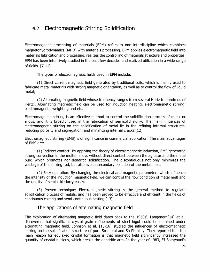
For what concerns hardness, with a 2.0 vol% SiC nanoparticles an approximately 20% hardness improvement was achieved [5] compared to aluminum alloy obtained by regular casting. However, it can be observed (fig.15) that the hardness of unreinforced alloy samples under ultrasonic processing is lower than that of regular casting. This can be due to a too violent acoustic streaming on the melt surface, that causes argon bubbles trapping into the metal and a consequently hardness degradation. This phenomenon can be eliminated by vacuum environment and optimized process parameters.
25
Figure 14: strengths of A356 alloy composite by ultrasonic assisted casting [4].
Figure 15: hardness of (A) aluminum alloy by regular casting; (B) aluminum alloy by ultrasonicassisted casting; (C) aluminum matrix nanocomposite by ultrasonicassisted casting [5].
26
4.2 Electromagnetic Stirring Solidification
Electromagnetic processing of materials (EPM) refers to one interdiscipline which combines magnetohydrodynamics (MHD) with materials processing. EPM applies electromagnetic field into materials fabrication and processing, realizes the controlling of materials structure and properties. EPM has been intensively studied in the past few decades and realized utilization in a wide range of fields. [7-11].
The types of electromagnetic fields used in EPM include:
(1) Direct current magnetic field generated by traditional coils, which is mainly used to fabricate metal materials with strong magnetic orientation, as well as to control the flow of liquid metal;
(2) Alternating magnetic field whose frequency ranges from several Hertz to hundreds of Hertz.. Alternating magnetic field can be used for induction heating, electromagnetic stirring, electromagnetic weighting and etc.
Electromagnetic stirring is an effective method to control the solidification process of metal or alloys, and it is broadly used in the fabrication of semisolid slurry. The main influences of electromagnetic stirring on the solidification of metal lie in the refining internal structures, reducing porosity and segregation, and minimizing internal cracks.[12]
Electromagnetic stirring (EMS) is of significance in commercial application. The main advantages of EMS are:
(1) Indirect contact: By applying the theory of electromagnetic induction, EMS generated strong convection in the molten alloys without direct contact between the agitator and the metal bulk, which promotes non-dendritic solidification. The discontiguous not only minimizes the wastage of the stirring rod, but also avoids secondary pollution of the metal melt.
(2) Easy operation: By changing the electrical and magnetic parameters which influence the intensity of the induction magnetic field, we can control the flow condition of metal melt and the quality of semisolid slurry easily.
(3) Proven technique: Electromagnetic stirring is the general method to regulate solidification process of metals, and has been proved to be effective and efficient in the fields of continuous casting and semi-continuous casting [13].
The applications of alternating magnetic field
The exploration of alternating magnetic field dates back to the 1960s'. Langenerg[14] et al. discovered that significant crystal grain refinements of steel ingot could be obtained under alternating magnetic field. Johnson et al. [15-16] studied the influences of electromagnetic stirring on the solidification structure of pure Sn metal and Sn-Pb alloy. They reported that the main reason for equiaxed crystal formation is that magnetic field significantly increased the quantity of crystal nucleus, which breaks the dendritic arm. In the year of 1983, EI-Bassyouni's
27
experiment [17] proved that alternating magnetic field could greatly refine crystal grain, and the optimal intensity of electromagnetic field is: 0.027 T--0.037 T, which is unrelated to the alloy materials. In 1986, Vives [18] studied the influence of natural convection and forced convection on the solidification of pure metal. He reported that the type of convection in the molten metal has crucial effect on the crystal structure and grain size, electromagnetic stirring is the main reason to determine the solidification structure. After that, Vives [19-20] also studied the distribution of electromagnetic field and fluid flow during the semi-continuous casting of 2214 Aluminum alloy, which is stirred by induction current under the power frequency of alternating magnetic field.
Mechanism of electromagnetic
The basic mechanism of electromagnetic processing can be best explained by the study of the Maxwell stress tensor, which demonstrates how an applied magnetic field affects the solidifying melt [21].
Electromagnetic Field
The governing equation for the distribution of the electromagnetic field in the crucible induction furnace is defined as the quasi-static subset of Maxwell's equation [22-23].
(1)
(2)
(3)
Also, with the possibly nonlinear material relationship
(4)
Together with Ohm's Law:
(5)
We assumed that in these equations:
(Ⅰ)Displacement current ;
(Ⅱ)Electric fields induced by the motion of the molten metal are negligible.
For the axisymmetric furnace geometry, defining a vector potential A in terms of the magnetic flux density B is helpful, so:
(6)
28
Substitute (6) into (1) for B, the electric field strength E could be:
(7)
The electric field generated by an applied e.m.f. is the first term in (7); the second term expresses the induced electric field. The function of the coordinates(r, z), which has a single component in
the azimuthal direction (if the slightly helical shape of the furnace coil is neglected) and a sinusoidal time variation is the vector potential in this geometry. To make it easier, we represent
the vector potential as a phasor and factor out the time variation.
(8)
Where
(9)
Function Aθ(r,z) has both magnitude and phase.
Electromagnetic Forces
The interaction of the induced currents leads to the Lorentz force density, on the other hand, the applied magnetic field is:
(10)
Τhe Lorentz force has two components--- the radial and axial. By using equation (2) and (4) to substitute for J and H, the Lorentz force can be expressed as:
(11)
(11) can be expanded to yield, in the case of linear magnetic materials,
(12)
This form is useful for the Lorentz force expression in that:
(I) The first term is the conservative component that electromagnetic pressure Pm derives the f:
(13)
29
The free surface meniscus results from force component.
(Ⅱ) The second term is the non-conservative component of f that is able to do work near a closed path.
In the regions where the magnetic flux density exhibits significant axial and radial variations, the
stirring forces will occur. Either end of the melt and at those section of the melt that coincide with the coil end planes are the ideal locations for the regions. There is an alternative formulation of the stirring forces we use to consider the Lorentz force rotation:
(14)
Most induction stirring applications are interested by only the time averaged forces. Hence, as indicated in the case of the vector potential by (8) and (9), it must be realized that the em fields are phasor quantities having magnitude and phase. If we have a solution for J and B, the time averaged Lorentz force is given by
(15)
In which Β* denotes a complex conjugate quantity. For more useful form of the time average force rotation:
(16)
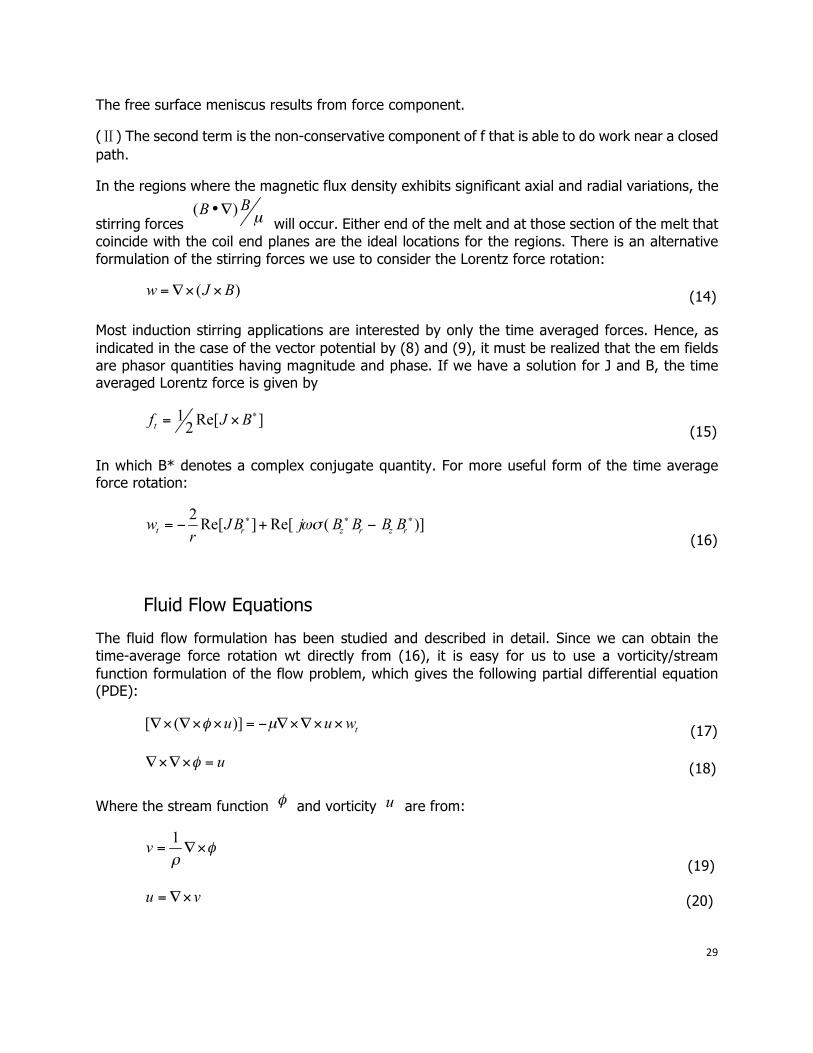
Fluid Flow Equations
The fluid flow formulation has been studied and described in detail. Since we can obtain the time-average force rotation wt directly from (16), it is easy for us to use a vorticity/stream function formulation of the flow problem, which gives the following partial differential equation (PDE):
(17)
(18)
Where the stream function and vorticity are from:
(19)
(20)
30
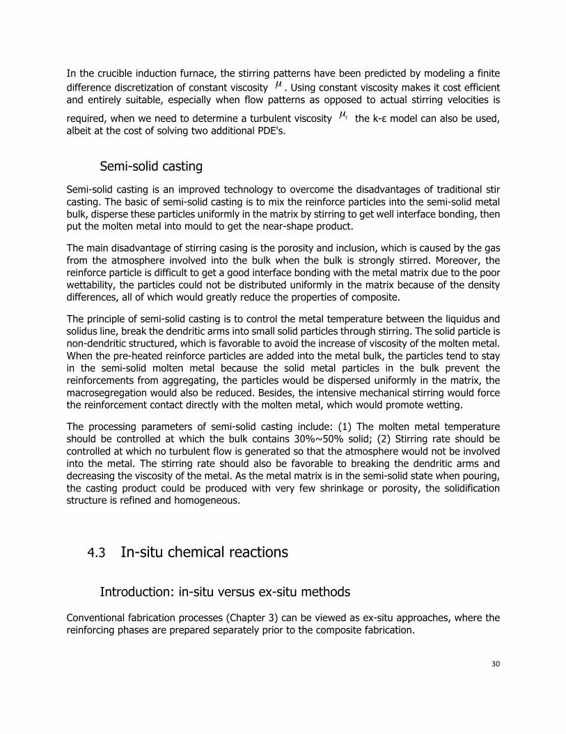
In the crucible induction furnace, the stirring patterns have been predicted by modeling a finite difference discretization of constant viscosity . Using constant viscosity makes it cost efficient and entirely suitable, especially when flow patterns as opposed to actual stirring velocities is
required, when we need to determine a turbulent viscosity the k-ε model can also be used, albeit at the cost of solving two additional PDE's.
Semi-solid casting
Semi-solid casting is an improved technology to overcome the disadvantages of traditional stir casting. The basic of semi-solid casting is to mix the reinforce particles into the semi-solid metal bulk, disperse these particles uniformly in the matrix by stirring to get well interface bonding, then put the molten metal into mould to get the near-shape product.
The main disadvantage of stirring casing is the porosity and inclusion, which is caused by the gas from the atmosphere involved into the bulk when the bulk is strongly stirred. Moreover, the reinforce particle is difficult to get a good interface bonding with the metal matrix due to the poor wettability, the particles could not be distributed uniformly in the matrix because of the density differences, all of which would greatly reduce the properties of composite.
The principle of semi-solid casting is to control the metal temperature between the liquidus and solidus line, break the dendritic arms into small solid particles through stirring. The solid particle is non-dendritic structured, which is favorable to avoid the increase of viscosity of the molten metal. When the pre-heated reinforce particles are added into the metal bulk, the particles tend to stay in the semi-solid molten metal because the solid metal particles in the bulk prevent the reinforcements from aggregating, the particles would be dispersed uniformly in the matrix, the macrosegregation would also be reduced. Besides, the intensive mechanical stirring would force the reinforcement contact directly with the molten metal, which would promote wetting.
The processing parameters of semi-solid casting include: (1) The molten metal temperature should be controlled at which the bulk contains 30%~50% solid; (2) Stirring rate should be controlled at which no turbulent flow is generated so that the atmosphere would not be involved into the metal. The stirring rate should also be favorable to breaking the dendritic arms and decreasing the viscosity of the metal. As the metal matrix is in the semi-solid state when pouring, the casting product could be produced with very few shrinkage or porosity, the solidification structure is refined and homogeneous.
4.3 In-situ chemical reactions Introduction: in-situ versus ex-situ methods
Conventional fabrication processes (Chapter 3) can be viewed as ex-situ approaches, where the reinforcing phases are prepared separately prior to the composite fabrication.
31
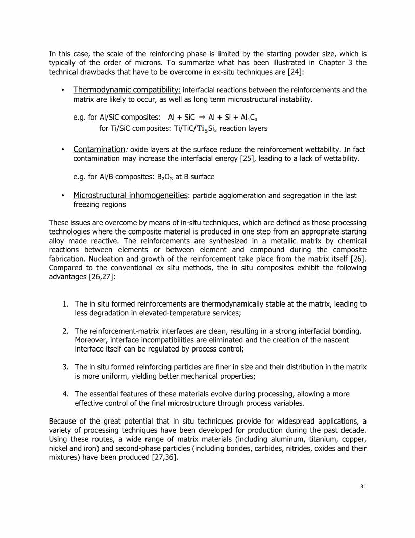
In this case, the scale of the reinforcing phase is limited by the starting powder size, which is typically of the order of microns. To summarize what has been illustrated in Chapter 3 the technical drawbacks that have to be overcome in ex-situ techniques are [24]:
• Thermodynamic compatibility: interfacial reactions between the reinforcements and the matrix are likely to occur, as well as long term microstructural instability. e.g. for Al/SiC composites: Al + SiC Al + Si + Al₄C₃ for Ti/SiC composites: Ti/TiC/ Si₃ reaction layers
• Contamination: oxide layers at the surface reduce the reinforcement wettability. In fact contamination may increase the interfacial energy [25], leading to a lack of wettability. e.g. for Al/B composites: B₂O₃ at B surface
• Microstructural inhomogeneities: particle agglomeration and segregation in the last freezing regions
These issues are overcome by means of in-situ techniques, which are defined as those processing technologies where the composite material is produced in one step from an appropriate starting alloy made reactive. The reinforcements are synthesized in a metallic matrix by chemical reactions between elements or between element and compound during the composite fabrication. Nucleation and growth of the reinforcement take place from the matrix itself [26]. Compared to the conventional ex situ methods, the in situ composites exhibit the following advantages [26,27]:
1. The in situ formed reinforcements are thermodynamically stable at the matrix, leading to less degradation in elevated-temperature services;
2. The reinforcement-matrix interfaces are clean, resulting in a strong interfacial bonding. Moreover, interface incompatibilities are eliminated and the creation of the nascent interface itself can be regulated by process control;
3. The in situ formed reinforcing particles are finer in size and their distribution in the matrix
is more uniform, yielding better mechanical properties;
4. The essential features of these materials evolve during processing, allowing a more effective control of the final microstructure through process variables.
Because of the great potential that in situ techniques provide for widespread applications, a variety of processing techniques have been developed for production during the past decade. Using these routes, a wide range of matrix materials (including aluminum, titanium, copper, nickel and iron) and second-phase particles (including borides, carbides, nitrides, oxides and their mixtures) have been produced [27,36].
32
The use of in-situ formed composites can cover a wide spectrum of industrial as well as high-performance applications [26]. Some of them are listed below:
• Composites for the automotive market; • Wear-resistant aluminum alloys; • Thermally-stable aluminum alloys; • Alloys characterized by high strength, high modulus and high thermal conductivity; • Squeeze-cast or injection-molded aluminum alloys
Commercial application of these in situ processing technologies requires an understanding of several key processing steps. However, the mechanisms responsible for in situ formation of ceramic reinforcements in the metallic matrix are not well understood. Therefore, several issues still need to be addressed by the research to reach a deep comprehension of the phenomenon [27].
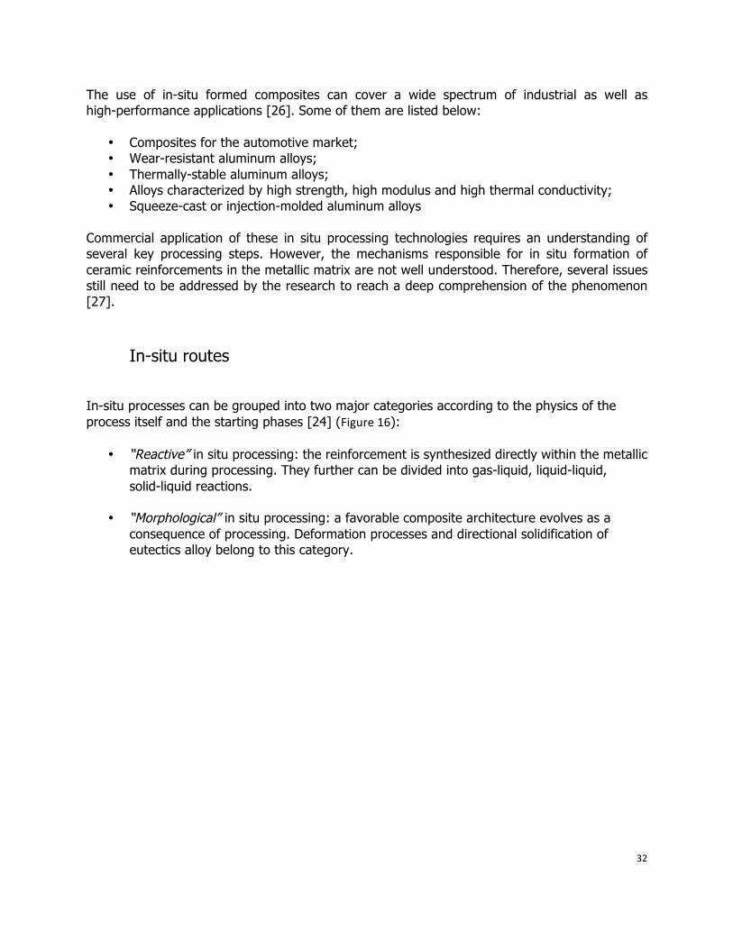
In-situ routes
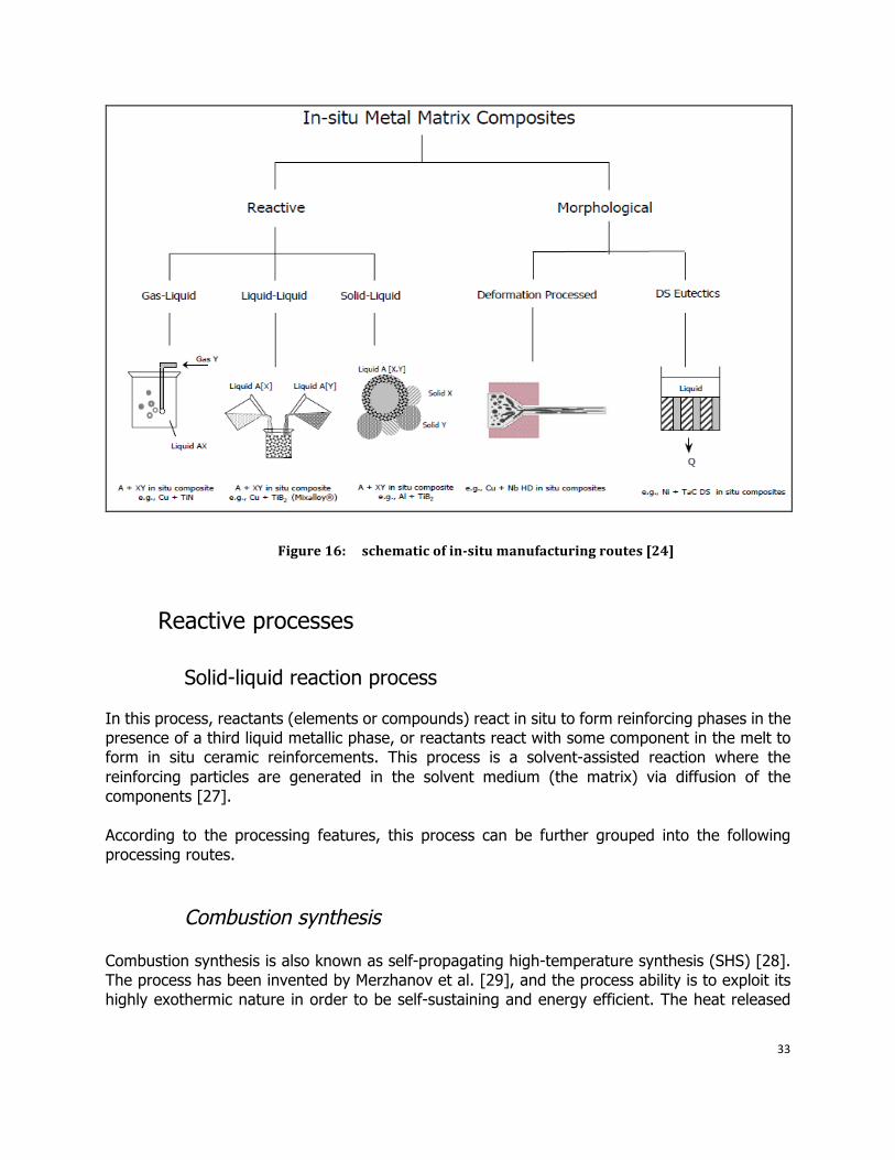
In-situ processes can be grouped into two major categories according to the physics of the process itself and the starting phases [24] (Figure16):
• “Reactive” in situ processing: the reinforcement is synthesized directly within the metallic matrix during processing. They further can be divided into gas-liquid, liquid-liquid, solid-liquid reactions.
• “Morphological” in situ processing: a favorable composite architecture evolves as a
consequence of processing. Deformation processes and directional solidification of eutectics alloy belong to this category.
33
Figure 16: schematic of insitu manufacturing routes [24]
Reactive processes
Solid-liquid reaction process
In this process, reactants (elements or compounds) react in situ to form reinforcing phases in the presence of a third liquid metallic phase, or reactants react with some component in the melt to form in situ ceramic reinforcements. This process is a solvent-assisted reaction where the reinforcing particles are generated in the solvent medium (the matrix) via diffusion of the components [27]. According to the processing features, this process can be further grouped into the following processing routes.
Combustion synthesis
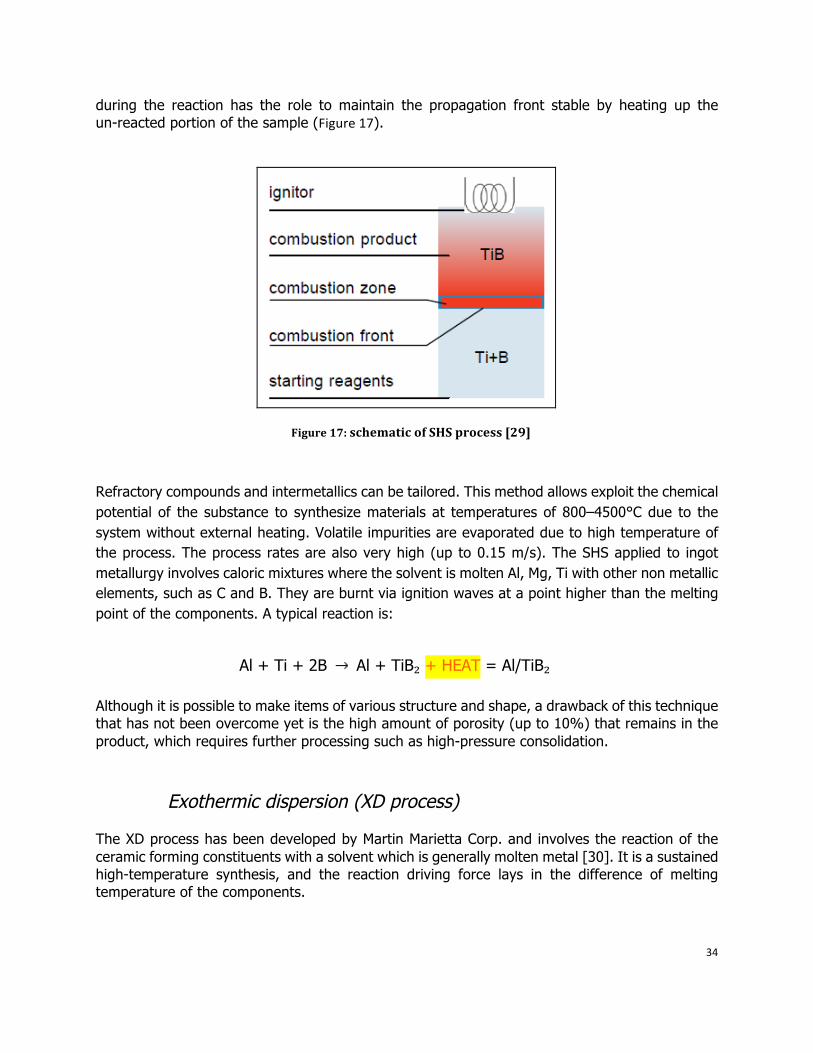
Combustion synthesis is also known as self-propagating high-temperature synthesis (SHS) [28]. The process has been invented by Merzhanov et al. [29], and the process ability is to exploit its highly exothermic nature in order to be self-sustaining and energy efficient. The heat released
34
during the reaction has the role to maintain the propagation front stable by heating up the un-reacted portion of the sample (Figure17).
Figure 17: schematic of SHS process [29]
Refractory compounds and intermetallics can be tailored. This method allows exploit the chemical potential of the substance to synthesize materials at temperatures of 800–4500°C due to the system without external heating. Volatile impurities are evaporated due to high temperature of the process. The process rates are also very high (up to 0.15 m/s). The SHS applied to ingot metallurgy involves caloric mixtures where the solvent is molten Al, Mg, Ti with other non metallic elements, such as C and B. They are burnt via ignition waves at a point higher than the melting point of the components. A typical reaction is:
Al + Ti + 2B Al + TiB₂ + HEAT = Al/TiB₂
Although it is possible to make items of various structure and shape, a drawback of this technique that has not been overcome yet is the high amount of porosity (up to 10%) that remains in the product, which requires further processing such as high-pressure consolidation.
Exothermic dispersion (XD process)
The XD process has been developed by Martin Marietta Corp. and involves the reaction of the ceramic forming constituents with a solvent which is generally molten metal [30]. It is a sustained high-temperature synthesis, and the reaction driving force lays in the difference of melting temperature of the components.
35
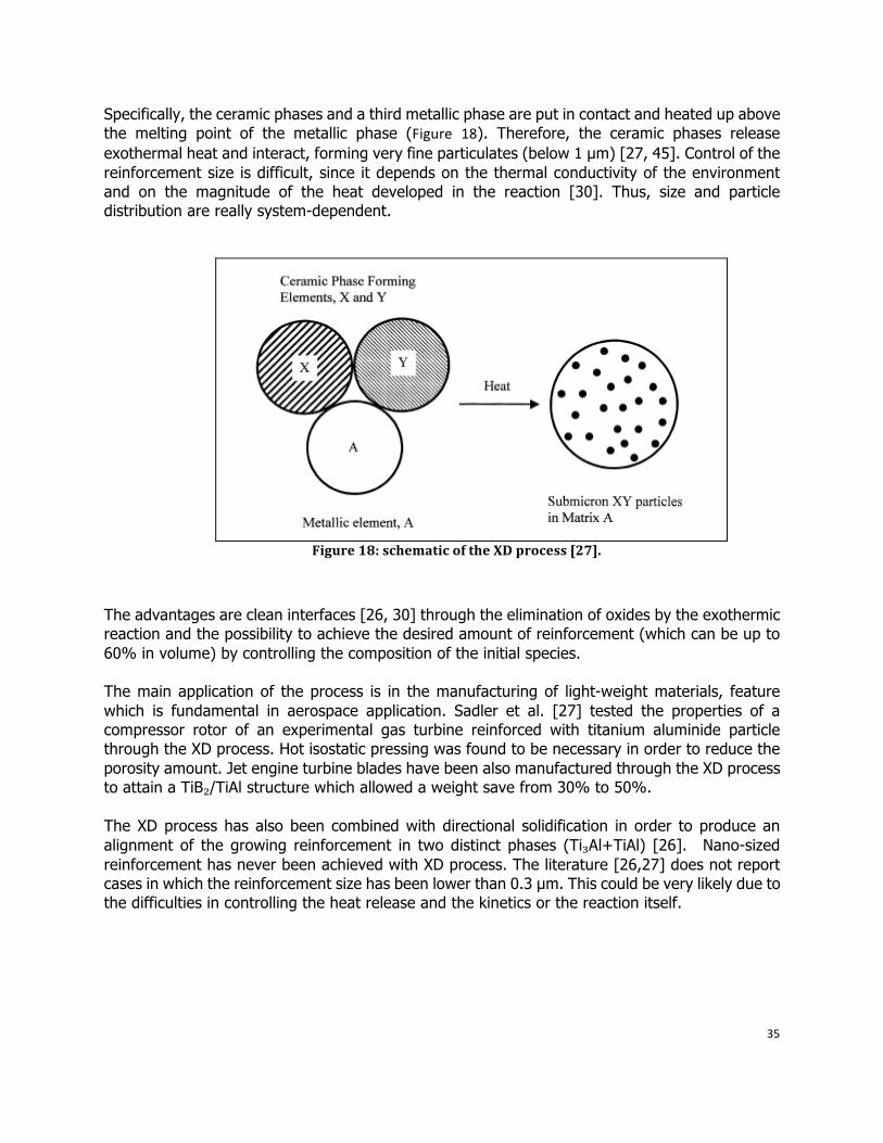
Specifically, the ceramic phases and a third metallic phase are put in contact and heated up above the melting point of the metallic phase (Figure 18). Therefore, the ceramic phases release exothermal heat and interact, forming very fine particulates (below 1 µm) [27, 45]. Control of the reinforcement size is difficult, since it depends on the thermal conductivity of the environment and on the magnitude of the heat developed in the reaction [30]. Thus, size and particle distribution are really system-dependent.
Figure 18: schematic of the XD process [27].
The advantages are clean interfaces [26, 30] through the elimination of oxides by the exothermic reaction and the possibility to achieve the desired amount of reinforcement (which can be up to 60% in volume) by controlling the composition of the initial species. The main application of the process is in the manufacturing of light-weight materials, feature which is fundamental in aerospace application. Sadler et al. [27] tested the properties of a compressor rotor of an experimental gas turbine reinforced with titanium aluminide particle through the XD process. Hot isostatic pressing was found to be necessary in order to reduce the porosity amount. Jet engine turbine blades have been also manufactured through the XD process to attain a TiB₂/TiAl structure which allowed a weight save from 30% to 50%. The XD process has also been combined with directional solidification in order to produce an alignment of the growing reinforcement in two distinct phases (Ti₃Al+TiAl) [26]. Nano-sized reinforcement has never been achieved with XD process. The literature [26,27] does not report cases in which the reinforcement size has been lower than 0.3 µm. This could be very likely due to the difficulties in controlling the heat release and the kinetics or the reaction itself.
36
Mixed salt reactions (Flux-assisted synthesis)
The mixed salt reaction process was developed by London and Scandinaviun Metallurgical Company. The basic concept comes from the purpose to produce grain refining aluminum alloys [27]. Mixed salts containing Ti and B with an atomic ratio in accordance with Ti/2B (K₂TiF₆ and KBF₄) are introduced into a stirred aluminum melt to form a fine dispersion. Pure Al and Al-Cu alloys reinforced with in situ TiB₂ particles have been successfully manufactured. The reactions are exothermal and the sequence of occurrence is [27]:
3K₂TiF₆ + 13Al 3TiAl₃ + 3KAlF₄ + K₃AlF₆ 2KBF + 3Al AlB₂ + 2KAlF₄
AlB₂ + TiAl₃ TiB₂ + 4Al In the invention of Chu et al. [31], carbide-forming refractory materials were added to the molten metal (Ti,Hf,Zr,Mo,Sc) and fine carbon particles introduced into the reactive salt. In some sections of the casting, large particles and areas characterized by an uneven dispersion can be seen. Chen et al. [54] and Chu et al [55] observed that when the amount of the salt differs from the Stoichiometric composition, other needle-like, brittle phases (Al₃Ti needles) form in addition to the TiB₂ particles. Despite the relatively short reaction times allowing a fast and easy scalable process, mixed salt reaction is characterized by several drawbacks. First of all, the slug produced by the salts must be taken out from the aluminum melt. In addition to this, it has been pointed out by Koczak et al [38] that the particles could be coated with unwanted reaction product that could weaken the strength of the material and lower the reaction rate.
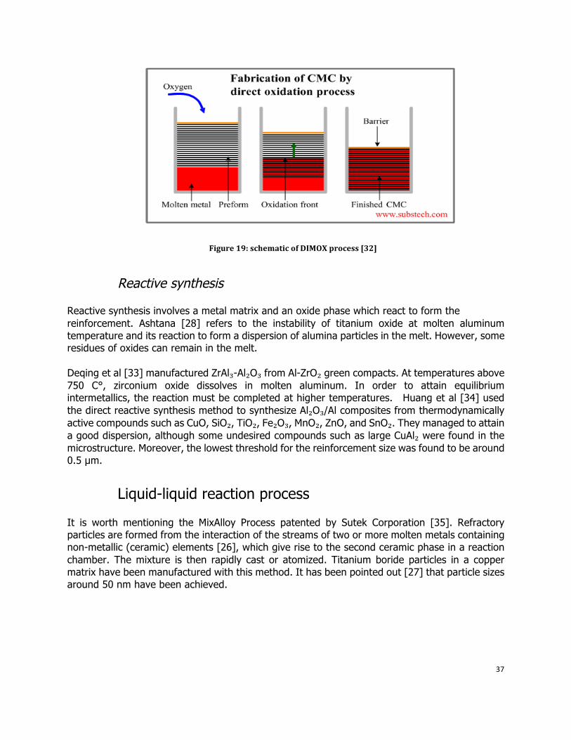
Direct metal oxidation (DIMOX)
The DIMOX process (Figure 19) was developed by Lanxide Corporation, where the liquid metal is oxidized at very high temperatures, such as 1700 K for aluminum alloys. The products of the reactions grow from the interface and the growth continues by transportation of the liquid to reach the interface through microchannels. Capillary forces are necessary to sustain the reaction, where the ceramic preform must be continuously infiltrated by the oxidating molten alloy. The disadvantage of the process is the low productivity: the growth rate is 1 mm/hour.
37
Figure 19: schematic of DIMOX process [32]
Reactive synthesis
Reactive synthesis involves a metal matrix and an oxide phase which react to form the reinforcement. Ashtana [28] refers to the instability of titanium oxide at molten aluminum temperature and its reaction to form a dispersion of alumina particles in the melt. However, some residues of oxides can remain in the melt. Deqing et al [33] manufactured ZrAl₃-Al₂O₃ from Al-ZrO₂ green compacts. At temperatures above 750 C°, zirconium oxide dissolves in molten aluminum. In order to attain equilibrium intermetallics, the reaction must be completed at higher temperatures. Huang et al [34] used the direct reactive synthesis method to synthesize Al₂O₃/Al composites from thermodynamically active compounds such as CuO, SiO₂, TiO₂, Fe₂O₃, MnO₂, ZnO, and SnO₂. They managed to attain a good dispersion, although some undesired compounds such as large CuAl₂ were found in the microstructure. Moreover, the lowest threshold for the reinforcement size was found to be around 0.5 µm.
Liquid-liquid reaction process
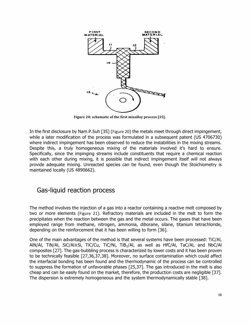
It is worth mentioning the MixAlloy Process patented by Sutek Corporation [35]. Refractory particles are formed from the interaction of the streams of two or more molten metals containing non-metallic (ceramic) elements [26], which give rise to the second ceramic phase in a reaction chamber. The mixture is then rapidly cast or atomized. Titanium boride particles in a copper matrix have been manufactured with this method. It has been pointed out [27] that particle sizes around 50 nm have been achieved.
38
Figure 20: schematic of the first mixalloy process [35].
In the first disclosure by Nam.P.Suh [35] (Figure20) the metals meet through direct impingement, while a later modification of the process was formulated in a subsequent patent (US 4706730) where indirect impingement has been observed to reduce the instabilities in the mixing streams. Despite this, a truly homogeneous mixing of the materials involved it’s hard to ensure. Specifically, since the impinging streams include constituents that require a chemical reaction with each other during mixing, it is possible that indirect impingement itself will not always provide adequate mixing. Unreacted species can be found, even though the Stoichiometry is maintained locally (US 4890662).
Gas-liquid reaction process
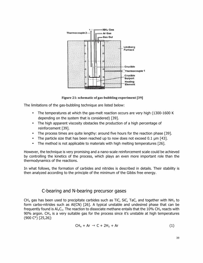
The method involves the injection of a gas into a reactor containing a reactive melt composed by two or more elements (Figure 21). Refractory materials are included in the melt to form the precipitates when the reaction between the gas and the metal occurs. The gases that have been employed range from methane, nitrogen, ammonia, diborane, silane, titanium tetrachloride, depending on the reinforcement that it has been willing to form [36].
One of the main advantages of the method is that several systems have been processed: TiC/Al, AlN/Al, TiN/Al, SiC/Al±Si, TiC/Cu, TiC/Ni, TiB₂/Al, as well as HfC/Al, TaC/Al, and NbC/Al composites [27]. The gas-bubbling process is characterized by lower costs and it has been proven to be technically feasible [27,36,37,38]. Moreover, no surface contamination which could affect the interfacial bonding has been found and the thermodynamic of the process can be controlled to suppress the formation of unfavorable phases [25,37]. The gas introduced in the melt is also cheap and can be easily found on the market, therefore, the production costs are negligible [37]. The dispersion is extremely homogeneous and the system thermodynamically stable [38].
39
Figure 21: schematic of gasbubbling experiment [39]
The limitations of the gas-bubbling technique are listed below:
• The temperatures at which the gas-melt reaction occurs are very high (1300-1600 K depending on the system that is considered) [39].
• The high apparent viscosity obstacles the production of a high percentage of reinforcement [39].
• The process times are quite lengthy: around five hours for the reaction phase [39]. • The particle size that has been reached up to now does not exceed 0.1 µm [43]. • The method is not applicable to materials with high melting temperatures [26].
However, the technique is very promising and a nano-scale reinforcement scale could be achieved by controlling the kinetics of the process, which plays an even more important role than the thermodynamics of the reactions.
In what follows, the formation of carbides and nitrides is described in details. Their stability is then analyzed according to the principle of the minimum of the Gibbs free energy.
C-bearing and N-bearing precursor gases
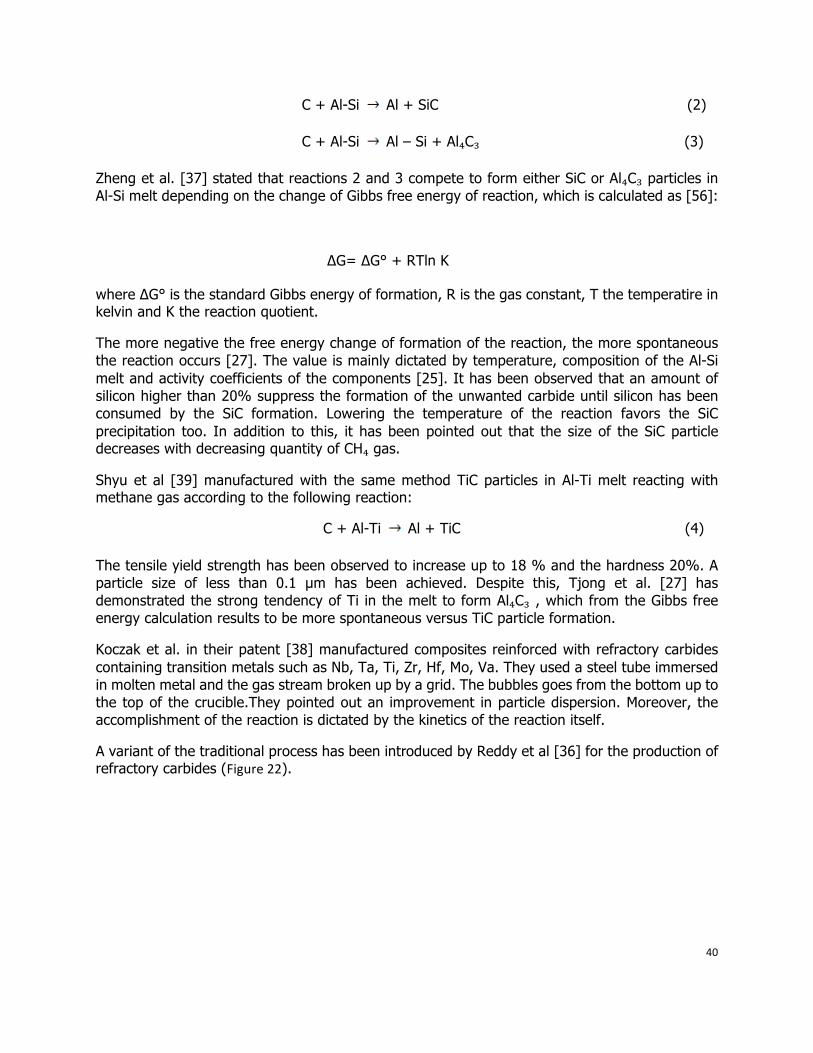
CH₄ gas has been used to precipitate carbides such as TiC, SiC, TaC, and together with NH₃ to form carbo-nitrides such as Al(CN) [26]. A typical unstable and undesired phase that can be frequently found is Al₄C₃. The reaction to dissociate methane entails that the 10% CH₄ reacts with 90% argon. CH₄ is a very suitable gas for the process since it’s unstable at high temperatures (900 C°) [25,26]:
CH₄ + Ar C + 2H₂ + Ar (1)
40
C + Al-Si Al + SiC (2)
C + Al-Si Al – Si + Al₄C₃ (3)
Zheng et al. [37] stated that reactions 2 and 3 compete to form either SiC or Al₄C₃ particles in Al-Si melt depending on the change of Gibbs free energy of reaction, which is calculated as [56]:
∆G= ∆G° + RTln K
where ∆G° is the standard Gibbs energy of formation, R is the gas constant, T the temperatire in kelvin and K the reaction quotient.
The more negative the free energy change of formation of the reaction, the more spontaneous the reaction occurs [27]. The value is mainly dictated by temperature, composition of the Al-Si melt and activity coefficients of the components [25]. It has been observed that an amount of silicon higher than 20% suppress the formation of the unwanted carbide until silicon has been consumed by the SiC formation. Lowering the temperature of the reaction favors the SiC precipitation too. In addition to this, it has been pointed out that the size of the SiC particle decreases with decreasing quantity of CH₄ gas.
Shyu et al [39] manufactured with the same method TiC particles in Al-Ti melt reacting with methane gas according to the following reaction:
C + Al-Ti Al + TiC (4)
The tensile yield strength has been observed to increase up to 18 % and the hardness 20%. A particle size of less than 0.1 µm has been achieved. Despite this, Tjong et al. [27] has demonstrated the strong tendency of Ti in the melt to form Al₄C₃ , which from the Gibbs free energy calculation results to be more spontaneous versus TiC particle formation.
Koczak et al. in their patent [38] manufactured composites reinforced with refractory carbides containing transition metals such as Nb, Ta, Ti, Zr, Hf, Mo, Va. They used a steel tube immersed in molten metal and the gas stream broken up by a grid. The bubbles goes from the bottom up to the top of the crucible.They pointed out an improvement in particle dispersion. Moreover, the accomplishment of the reaction is dictated by the kinetics of the reaction itself.
A variant of the traditional process has been introduced by Reddy et al [36] for the production of refractory carbides (Figure22).
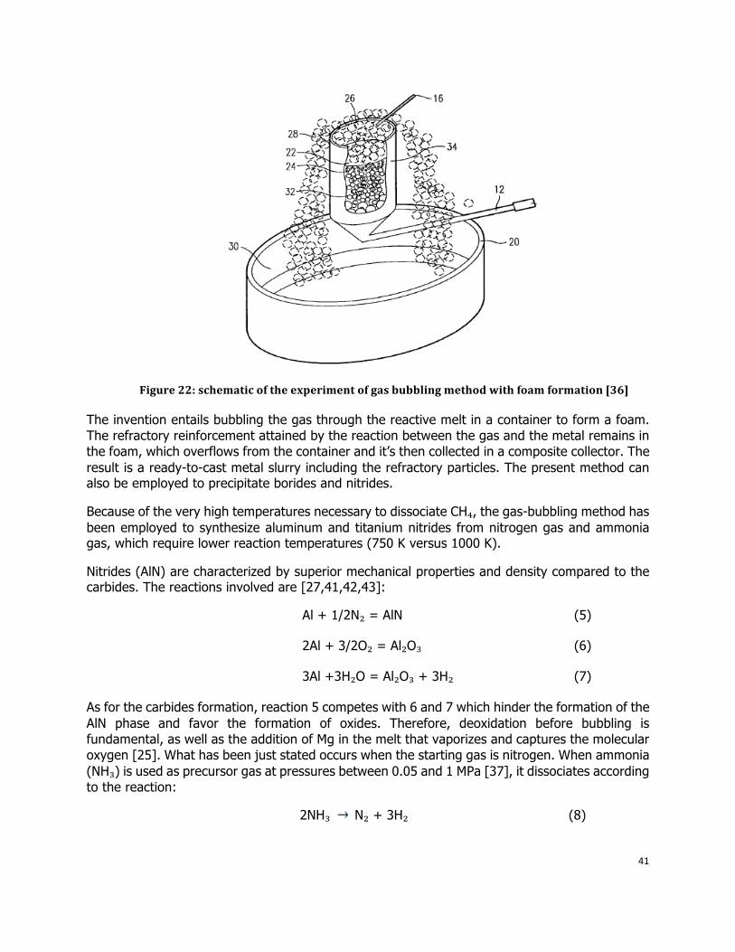
41
Figure 22: schematic of the experiment of gas bubbling method with foam formation [36]
The invention entails bubbling the gas through the reactive melt in a container to form a foam. The refractory reinforcement attained by the reaction between the gas and the metal remains in the foam, which overflows from the container and it’s then collected in a composite collector. The result is a ready-to-cast metal slurry including the refractory particles. The present method can also be employed to precipitate borides and nitrides.
Because of the very high temperatures necessary to dissociate CH₄, the gas-bubbling method has been employed to synthesize aluminum and titanium nitrides from nitrogen gas and ammonia gas, which require lower reaction temperatures (750 K versus 1000 K).
Nitrides (AlN) are characterized by superior mechanical properties and density compared to the carbides. The reactions involved are [27,41,42,43]:
Al + 1/2N₂ = AlN (5)
2Al + 3/2O₂ = Al₂O₃ (6)
3Al +3H₂O = Al₂O₃ + 3H₂ (7)
As for the carbides formation, reaction 5 competes with 6 and 7 which hinder the formation of the AlN phase and favor the formation of oxides. Therefore, deoxidation before bubbling is fundamental, as well as the addition of Mg in the melt that vaporizes and captures the molecular oxygen [25]. What has been just stated occurs when the starting gas is nitrogen. When ammonia (NH₃) is used as precursor gas at pressures between 0.05 and 1 MPa [37], it dissociates according to the reaction:
2NH₃ N₂ + 3H₂ (8)
42
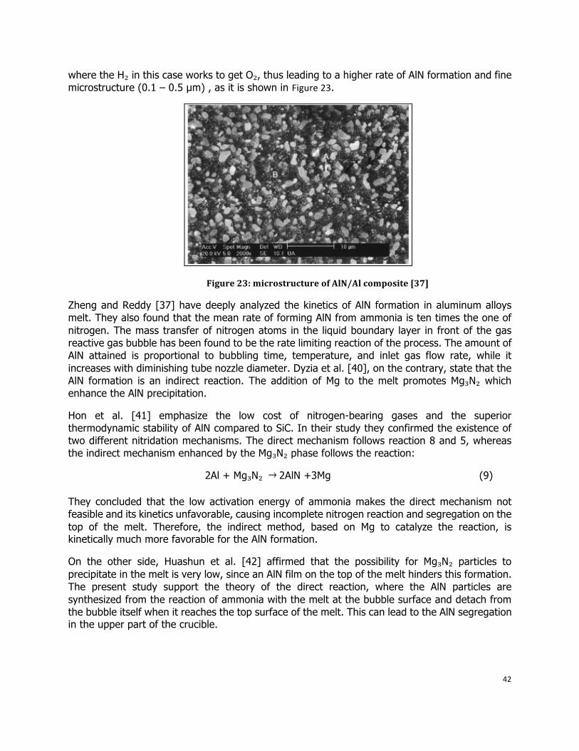
where the H₂ in this case works to get O₂, thus leading to a higher rate of AlN formation and fine microstructure (0.1 – 0.5 µm) , as it is shown in Figure23.
Figure 23: microstructure of AlN/Al composite [37]
Zheng and Reddy [37] have deeply analyzed the kinetics of AlN formation in aluminum alloys melt. They also found that the mean rate of forming AlN from ammonia is ten times the one of nitrogen. The mass transfer of nitrogen atoms in the liquid boundary layer in front of the gas reactive gas bubble has been found to be the rate limiting reaction of the process. The amount of AlN attained is proportional to bubbling time, temperature, and inlet gas flow rate, while it increases with diminishing tube nozzle diameter. Dyzia et al. [40], on the contrary, state that the AlN formation is an indirect reaction. The addition of Mg to the melt promotes Mg₃N₂ which enhance the AlN precipitation.
Hon et al. [41] emphasize the low cost of nitrogen-bearing gases and the superior thermodynamic stability of AlN compared to SiC. In their study they confirmed the existence of two different nitridation mechanisms. The direct mechanism follows reaction 8 and 5, whereas the indirect mechanism enhanced by the Mg₃N₂ phase follows the reaction:
2Al + Mg₃N₂ 2AlN +3Mg (9)
They concluded that the low activation energy of ammonia makes the direct mechanism not feasible and its kinetics unfavorable, causing incomplete nitrogen reaction and segregation on the top of the melt. Therefore, the indirect method, based on Mg to catalyze the reaction, is kinetically much more favorable for the AlN formation.
On the other side, Huashun et al. [42] affirmed that the possibility for Mg₃N₂ particles to precipitate in the melt is very low, since an AlN film on the top of the melt hinders this formation. The present study support the theory of the direct reaction, where the AlN particles are synthesized from the reaction of ammonia with the melt at the bubble surface and detach from the bubble itself when it reaches the top surface of the melt. This can lead to the AlN segregation in the upper part of the crucible.
43
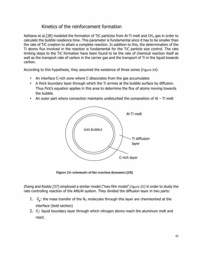
Kinetics of the reinforcement formation
Ashtana et al.[28] modeled the formation of TiC particles from Al-Ti melt and CH₄ gas in order to calculate the bubble residence time. This parameter is fundamental since it has to be smaller than the rate of TiC creation to attain a complete reaction. In addition to this, the determination of the Ti atoms flux involved in the reaction is fundamental for the TiC particle size control. The rate limiting steps to the TiC formation have been found to be the rate of chemical reaction itself as well as the transport rate of carbon in the carrier gas and the transport of Ti in the liquid towards carbon.
According to this hypothesis, they assumed the existence of three zones (Figure24):
• An interface C-rich zone where C dissociates from the gas accumulates • A thick boundary layer through which the Ti arrives at the bubble surface by diffusion.
Thus Fick’s equation applies in this area to determine the flux of atoms moving towards the bubble.
• An outer part where convection maintains undisturbed the composition of Al – Ti melt
Zheng and Reddy [37] employed a similar model (“two film model”,Figure25) in order to study the rate controlling reaction of the AlN/Al system. They divided the diffusion layer in two parts:
1. : the mass transfer of the N₂ molecules through this layer are chemisorbed at the
interface (bold section) 2. : liquid boundary layer through which nitrogen atoms reach the aluminum melt and
react.
Al-Ti melt
C-rich layer
Ti diffusion layer
GASBUBBLE
Figure 24: schematic of the reaction dynamics [28]
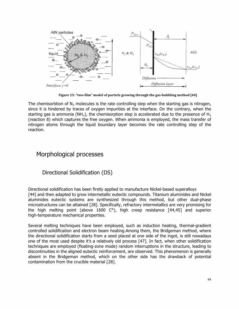
44
Figure 25: “twofilm” model of particle growing through the gasbubbling method [40]
The chemisorbtion of N₂ molecules is the rate controlling step when the starting gas is nitrogen, since it is hindered by traces of oxygen impurities at the interface. On the contrary, when the starting gas is ammonia (NH₃), the chemisorption step is accelerated due to the presence of H₂ (reaction 8) which captures the free oxygen. When ammonia is employed, the mass transfer of nitrogen atoms through the liquid boundary layer becomes the rate controlling step of the reaction.
Morphological processes Directional Solidification (DS)
Directional solidification has been firstly applied to manufacture Nickel-based superalloys [44] and then adapted to grow intermetallic eutectic compounds. Titanium aluminides and Nickel aluminides eutectic systems are synthesized through this method, but other dual-phase microstructures can be attained [28]. Specifically, refractory intermetallics are very promising for the high melting point (above 1600 C°), high creep resistance [44,45] and superior high-temperature mechanical properties. Several melting techniques have been employed, such as induction heating, thermal-gradient controlled solidification and electron beam heating.Among them, the Bridgeman method, where the directional solidification starts from a seed placed at one side of the ingot, is still nowadays one of the most used despite it’s a relatively old process [47]. In fact, when other solidification techniques are employed (floating-zone mode) random interruptions in the structure, leading to discontinuities in the aligned eutectic reinforcement, are observed. This phenomenon is generally absent in the Bridgeman method, which on the other side has the drawback of potential contamination from the crucible material [28].
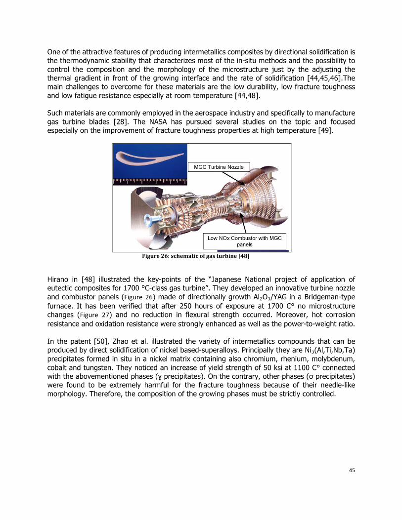
45
One of the attractive features of producing intermetallics composites by directional solidification is the thermodynamic stability that characterizes most of the in-situ methods and the possibility to control the composition and the morphology of the microstructure just by the adjusting the thermal gradient in front of the growing interface and the rate of solidification [44,45,46].The main challenges to overcome for these materials are the low durability, low fracture toughness and low fatigue resistance especially at room temperature [44,48]. Such materials are commonly employed in the aerospace industry and specifically to manufacture gas turbine blades [28]. The NASA has pursued several studies on the topic and focused especially on the improvement of fracture toughness properties at high temperature [49].
Figure 26: schematic of gas turbine [48]
Hirano in [48] illustrated the key-points of the “Japanese National project of application of eutectic composites for 1700 °C-class gas turbine”. They developed an innovative turbine nozzle and combustor panels (Figure 26) made of directionally growth Al₂O₃/YAG in a Bridgeman-type furnace. It has been verified that after 250 hours of exposure at 1700 C° no microstructure changes (Figure 27) and no reduction in flexural strength occurred. Moreover, hot corrosion resistance and oxidation resistance were strongly enhanced as well as the power-to-weight ratio. In the patent [50], Zhao et al. illustrated the variety of intermetallics compounds that can be produced by direct solidification of nickel based-superalloys. Principally they are Ni₃(Al,Ti,Nb,Ta) precipitates formed in situ in a nickel matrix containing also chromium, rhenium, molybdenum, cobalt and tungsten. They noticed an increase of yield strength of 50 ksi at 1100 C° connected with the abovementioned phases (ɣ precipitates). On the contrary, other phases (σ precipitates) were found to be extremely harmful for the fracture toughness because of their needle-like morphology. Therefore, the composition of the growing phases must be strictly controlled.
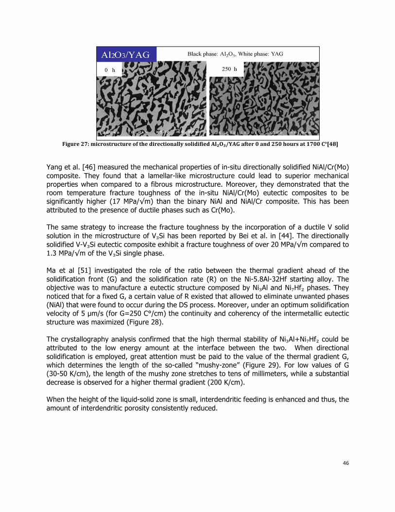
46
Figure 27: microstructure of the directionally solidified Al₂O₃/YAG after 0 and 250 hours at 1700 C°[48]
Yang et al. [46] measured the mechanical properties of in-situ directionally solidified NiAl/Cr(Mo) composite. They found that a lamellar-like microstructure could lead to superior mechanical properties when compared to a fibrous microstructure. Moreover, they demonstrated that the room temperature fracture toughness of the in-situ NiAl/Cr(Mo) eutectic composites to be significantly higher (17 MPa/√m) than the binary NiAl and NiAl/Cr composite. This has been attributed to the presence of ductile phases such as Cr(Mo). The same strategy to increase the fracture toughness by the incorporation of a ductile V solid solution in the microstructure of V₃Si has been reported by Bei et al. in [44]. The directionally solidified V-V₃Si eutectic composite exhibit a fracture toughness of over 20 MPa/√m compared to 1.3 MPa/√m of the V₃Si single phase. Ma et al [51] investigated the role of the ratio between the thermal gradient ahead of the solidification front (G) and the solidification rate (R) on the Ni-5.8Al-32Hf starting alloy. The objective was to manufacture a eutectic structure composed by Ni₃Al and Ni₇Hf₂ phases. They noticed that for a fixed G, a certain value of R existed that allowed to eliminate unwanted phases (NiAl) that were found to occur during the DS process. Moreover, under an optimum solidification velocity of 5 µm/s (for G=250 C°/cm) the continuity and coherency of the intermetallic eutectic structure was maximized (Figure 28). The crystallography analysis confirmed that the high thermal stability of Ni₃Al+Ni₇Hf₂ could be attributed to the low energy amount at the interface between the two. When directional solidification is employed, great attention must be paid to the value of the thermal gradient G, which determines the length of the so-called “mushy-zone” (Figure 29). For low values of G (30-50 K/cm), the length of the mushy zone stretches to tens of millimeters, while a substantial decrease is observed for a higher thermal gradient (200 K/cm). When the height of the liquid-solid zone is small, interdendritic feeding is enhanced and thus, the amount of interdendritic porosity consistently reduced.
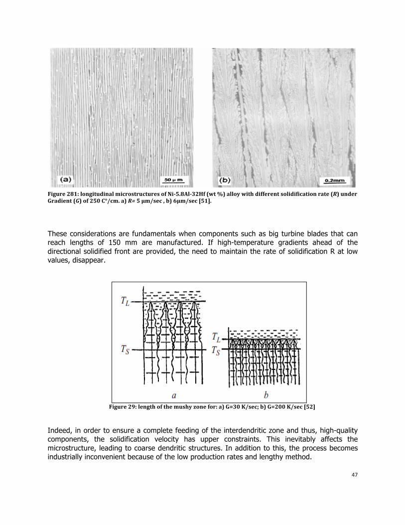
47
Figure 281: longitudinal microstructures of Ni5.8Al32Hf (wt %) alloy with different solidification rate (R) under Gradient (G) of 250 C°/cm. a) R= 5 µm/sec , b) 6µm/sec [51].
These considerations are fundamentals when components such as big turbine blades that can reach lengths of 150 mm are manufactured. If high-temperature gradients ahead of the directional solidified front are provided, the need to maintain the rate of solidification R at low values, disappear.
Figure 29: length of the mushy zone for: a) G=30 K/sec; b) G=200 K/sec [52]
Indeed, in order to ensure a complete feeding of the interdendritic zone and thus, high-quality components, the solidification velocity has upper constraints. This inevitably affects the microstructure, leading to coarse dendritic structures. In addition to this, the process becomes industrially inconvenient because of the low production rates and lengthy method.
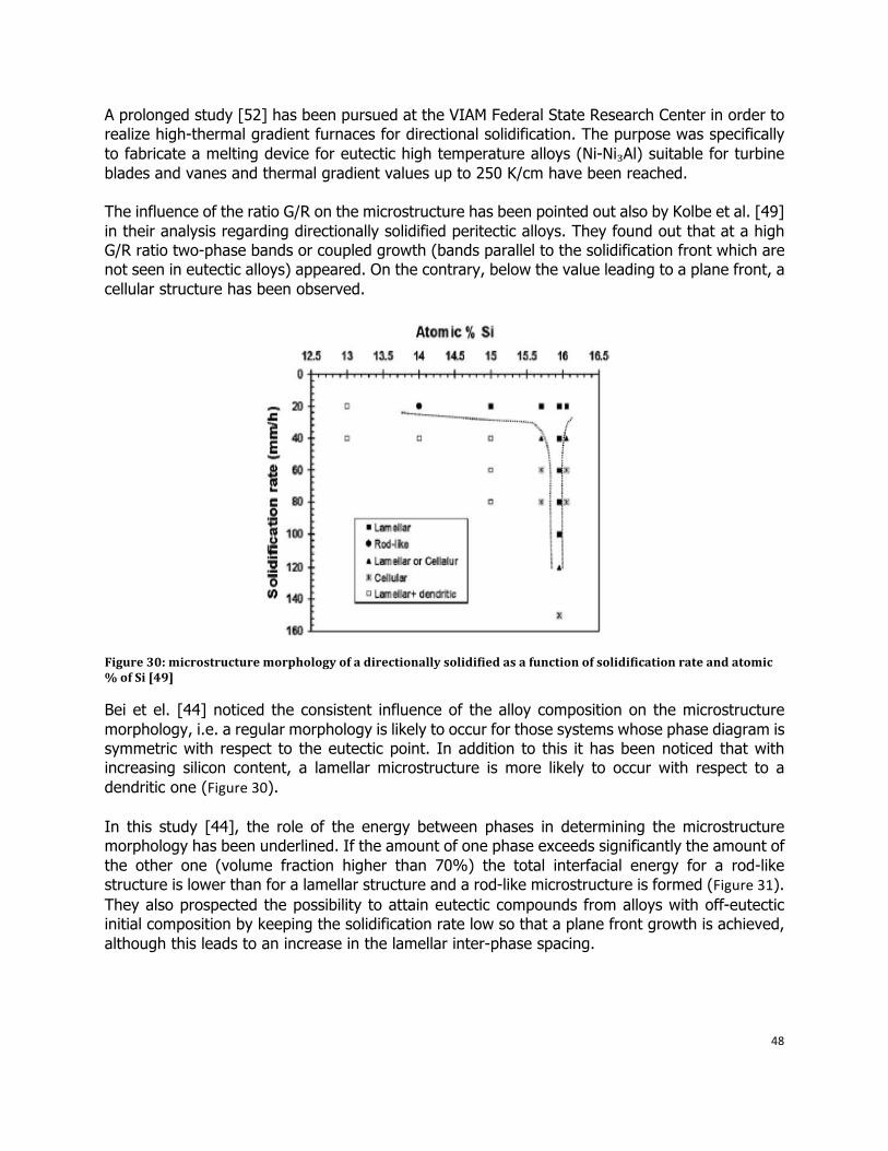
48
A prolonged study [52] has been pursued at the VIAM Federal State Research Center in order to realize high-thermal gradient furnaces for directional solidification. The purpose was specifically to fabricate a melting device for eutectic high temperature alloys (Ni-Ni₃Al) suitable for turbine blades and vanes and thermal gradient values up to 250 K/cm have been reached. The influence of the ratio G/R on the microstructure has been pointed out also by Kolbe et al. [49] in their analysis regarding directionally solidified peritectic alloys. They found out that at a high G/R ratio two-phase bands or coupled growth (bands parallel to the solidification front which are not seen in eutectic alloys) appeared. On the contrary, below the value leading to a plane front, a cellular structure has been observed.
Figure 30: microstructure morphology of a directionally solidified as a function of solidification rate and atomic % of Si [49]
Bei et el. [44] noticed the consistent influence of the alloy composition on the microstructure morphology, i.e. a regular morphology is likely to occur for those systems whose phase diagram is symmetric with respect to the eutectic point. In addition to this it has been noticed that with increasing silicon content, a lamellar microstructure is more likely to occur with respect to a dendritic one (Figure30).
In this study [44], the role of the energy between phases in determining the microstructure morphology has been underlined. If the amount of one phase exceeds significantly the amount of the other one (volume fraction higher than 70%) the total interfacial energy for a rod-like structure is lower than for a lamellar structure and a rod-like microstructure is formed (Figure31). They also prospected the possibility to attain eutectic compounds from alloys with off-eutectic initial composition by keeping the solidification rate low so that a plane front growth is achieved, although this leads to an increase in the lamellar inter-phase spacing.
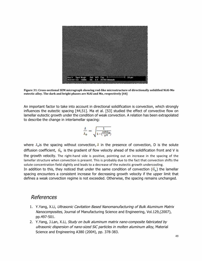
49
Figure 31: Crosssectional SEM micrograph showing rodlike microstructure of directionally solidified NiAlMo eutectic alloy. The dark and bright phases are NiAl and Mo, respectively [44]
An important factor to take into account in directional solidification is convection, which strongly influences the eutectic spacing [44,51]. Ma et al. [53] studied the effect of convective flow on lamellar eutectic growth under the condition of weak convection. A relation has been extrapolated to describe the change in interlamellar spacing:
where is the spacing without convection, in the presence of convection, D is the solute diffusion coefficient, is the gradient of flow velocity ahead of the solidification front and V is the growth velocity. The right‐hand side is positive, pointing out an increase in the spacing of thelamellarstructurewhenconvectionispresent.Thisisprobablyduetothefactthatconvectionshiftsthesoluteconcentrationfieldslightlyandleadstoadecreaseoftheeutecticgrowthundercooling. In addition to this, they noticed that under the same condition of convection ( ) the lamellar spacing encounters a consistent increase for decreasing growth velocity if the upper limit that defines a weak convection regime is not exceeded. Otherwise, the spacing remains unchanged.
References
1. Y.Yang, X.Li, Ultrasonic Cavitation Based Nanomanufacturing of Bulk Aluminum Matrix Nanocomposites, Journal of Manufacturing Science and Engineering, Vol.129,(2007), pp.497-501.
2. Y.Yang, J.Lan, X.Li, Study on bulk aluminum matrix nano-composite fabricated by ultrasonic dispersion of nano-sized SiC particles in molten aluminum alloy, Material Science and Engineering A380 (2004), pp. 378-383.
50
3. T.M. Angeliu, Method for making materials having artificially dispersed nano-sized phases and articles made therewith, United States Patent US 6,939,388 B2, Sept.6,2005.
4. Y.Yang, X.Li, D.Weiss, Theoretical and Experimental Study on Ultrasonic Cavitation Based Solidification Processing of Bulk Aluminum Matrix Nanocomposite, American Foundry Society Copyright (2007).
5. Y.Yang, X.Li, X.Cheng, Ultrasonic-assisted fabrication of metal matrix nanocomposites, Journal of material science, Vol.39 (2004), pp.3211-3212
6. H.Xu, Q.Han, T. Meek, Effects of ultrasonic vibration on degassing aluminum alloys, Materials Science and Engineering A 473 (2008), pp. 96–104.
7. Boettinger W J, Coriell S R, Greer A L, Karma A, Kurz W, Rappaz M, Trivedi R. Solidification microstructures: recent developments, future directions[J], Acta materials, 2000,48:43-70.
8. Hunt J C R. Magnetohydrodynamic flow in rectangular ducts[J], Journal of Fluid mechanics, 1965,21:577-590.
9. Farrel D E. Effect of flow on morphological stability during directional solidification[J], Physical Review B, 1987,36(7):4025-4027.
10. Uhlmann D R, Seward T P, Chalmers B. The effect of magnetic fields on the structure of metal alloy castings[J], Trans Metall Soc AIME, 1966, 236(4):527-535.
11. Kishida Y, Takeda K, Miyoshino I, et al. Anisotropic effect of magnetohydro-dynamics on metal solidification[J], ISJJ int, 1990, 30(1):34-40.
12. Wu X Q, Zhan Q, Yang Y S, et al. The effect of electromagnetic stirring during solidification of the structure of Al-Si alloys[J], J Mater Sci Lett, 1998, (17):1403-1405
13. Ren Z M, Jin J Z. Some aspects of electromagnetic casting of aluminum[J], Light Metals, 1992:1263-1267
14. Langenberg F C, Pestel G, Honeycutt C R. Grain refinement of steel ingots by solidification in a moving electromagnetic field[J], Trans Metall Soc AIME, 1961, 221:993-1001
15. Johnston W C, Kotler G R, Tiller W A. The influence of electromagnetic stirring on the nucleation of Tin and Tin-lead alloy[J], Trans Metall Soc AIME, 1963, 227(4):890-896
16. Johnston W C, Kotler G R, Tiller W A. Grain refinement via electromagnetic sitting during solidification[J], Trans Metall Soc AIME, 1965, 233(9): 1856-1960
17. El-Bassyouni T A. Effect of electromagnetic forces on aluminum cast structure[J], Light Metals, 1983, 33(12):733-742
18. Vives C. Solidification of Tin in the presence of electric and magnetic field[J], J Crystal Growth, 1986, 76:170-184
19. Vives C. Electromagnetic refining of aluminum alloys by the CREM process: Part I. Working principle and metallurgical results[J], Metall Trans B, 1989, 20B: 623-629
20. Vives C. Electromagnetic refining of aluminum alloys by the CREM process: Part II. Specific practical problems and their solutions[J], Metall Trans B, 1989, 20B: 631-643
21. Vives C. Effect of electromagnetic vibrations on microstructure of continuously cast aluminum alloys[J], Mater Sci Eng, 1993, A 173: 169-172
22. J.D.Jackson, Classical Electrodynamics (New York: John Wiley&Sons, 1975)
51
23. P.A. Davidson. An Introduction to Magnetohydrodynamics
24. S.L. Kampe, “ In situ Metal Matrix Composite Processing: An Overview”, 2006 ASM/TMS Spring Symposium, Multiphase and Composite Materials, Virginia Tech May 2006
25. Zheng, Wu, Reddy, “In-Situ Processing of Al Alloy Composites”, Advanced Engineering Materials 5, No. 3, pp. 167-173, 2003
26. D. Apelian, “Processing Challenges of Light Weight, Light Specific Strength Metallic Materials”.
27. S.C. Tjong, Z.Y. Ma, “Microstructural and mechanical characteristics of in situ metal matrix composites”, Material Science and Enginnering 29, Review Report,pp.49-113, 2000
28. R. Ashtana, “Solidification Processing of Reinforced Metals”, Trans. Tech Publications, 1997
29. A.G.Merzhanov, “Self-Propagating High-Temperature Synthesis (SHS)”, Institute of Structural Macrokinetics and Materials Science of the Russian Academy of Sciences.
30. SCH 31. Chu et al., “Metal Product Containing Dispersoid Form In-Situ”, US Patent 6723282, April
2004 32. www.subtech.com 33. W. Dequing, J. Neumann,H.F. Lopez,” Reactive Synthesis of In-Situ ZrAl3-Al2O3-Al
Composites”, Metallurgical and Material Transaction 34A, pp. 1357-1361, 2003 34. Huang, Yang, Cui, Duan, Zhang, “Microstructure of designed Al matrix composites
reinforced by combining in situ alloying elements and Al2O3(p)”, Journal of Material Science Letters 20, pp 1749-1751, 2001.
35. Nam P. Suh Sutek Corporation, “Mix alloy Process”, US Patent 4278622 and 4279843, July 1981.
36. Reddy et al. , “Production of Metal/Refractory Composites by Bubbling Gas Through a Melt” , US Patent 6343640, June 2002.
37. Zheng and Reddy, “Kinetics of In-Situ Formation of AlN in Al Alloy Melts by Bubbling Ammonia Gas”, Metallurgical and Material Transaction 34B, pp. 793-805, 2003.
38. Koczak et al., “In situ process for producing composite containing refractory material”, US Patent 4808372, February 1989.
39. Shyu and Ho, “In situ reacted titanium carbide-reinforced aluminum alloys composite”, Journal of Materials Processing Technology 171, pp. 411–416, 2006
40. M.Dyzia, J.Sleziona, “Aluminum Matrix Composites Reinforced with AlN particles formed by in situ reaction”, Archives of Material Science and Engineering 31, pp.17-20, 2008.
41. Hon, Mutharasan, Koczak, “Feasibility of aluminum nitride formation in aluminum alloys”, Materials Science and Engineering A195, pp. 121-129, 1995
42. Yu Huashun, J.D. Kim, S.B. Kang, “The formation of AlN and TiN particles during nitrogen bearing gas injection into Al–Mg–Ti melt”, Materials Science and Engineering A 386, pp. 318–325, 2004.
43. R.F. Shyu, F.T. Weng, C.T. Ho, “In situ reacted titanium nitride-reinforced aluminum alloy composite”, Journal of Materials Processing Technology 122, pp. 301–304, 2002
44. Bei, “A review of directionally solidified intermetallic composites for high-temperature structural applications”, Journal of materials science 39, pp.3975 – 3984, 2004
45. C.M.Ward-Close, Minor, Doorbar, “Intermetallic-matrix composites. A review”, Intermetallics 4,pp.217-229, 1996.
52
46. J.M.Yang, “ The mechanical behavior of in situ NiAl-refractory metal composites”, Journal of Materials Review, 1997
47. M.Fleming, “Solidification Processing”, Mc Graw-Hill, New York, 1974 48. Hirano, “Application of eutectic composites for 1700 °C-class gas turbine”,
Japanese National Project, 2007 49. Steinbach, Ratke, Masslow, “Directional Solidification of Binary AlSi-Alloys in diffusive and
convective regimes”, Symposium on European Rocket and Balloon Programmes and Related Research, 30 May - 2 June 2005, Sandefjord, Norway.
50. Zhao et al., “Nickel-base sigma-gamma in-situ intermetallic matrix composite”, US Patent 5858558.
51. S. W. Ma, Y. R. Zheng, Z. C. Ruan, “Investigation on Ni3Al-Ni7Hf2 unidirectionally solidified eutectic composite” Journal of materials science 34, pp. 5351 – 5356, 2006.
52. Yu. A. Bondarenko and E. N. Kablov, “Directional crystallization of high-temperature alloys with elevated temperature gradient”, Metal Science and Heat Treatment 44, 2002.
53. Ma, Jie, Li, NG, “Effect of weak convection on lamellar spacing of eutectics”, Acta Metallurgica 46, pp.3203-3210, 1998
54. Z.Y. Chen, Y.Y. Chen, Q. Shu, G. Y. An, D. LI, and Y.Y. Liu, “Microstructure and Properties of In Situ Al/TiB2 Composite Fabricated by In-Melt Reaction Method”, Metallurgical and material Transactions A 31A, pp. 1959-1965
55. Chu et al. ,” Liquid-state-in-situ formed ceramic particles in metals and alloys”, US Patent 6036792
56. Fast, “Interaction of metals and gases”, 1965
53
5. Proposed approach at ACRC
5.1 Electromagnetic stirring solidification
Objectives
Although aluminum matrix nano-composites are very promising for providing superior properties, especially high temperature properties, the current manufacturing technologies are neither reliable nor cost effective to enable a high volume and net shape production of complex structural components with reproducible structures and properties. We propose a new manufacturing route, which combines the electromagnetic stirring and semi-solid casting, to fabricate aluminum matrix nano-composite samples.
Electromagnetic stirring has been proved to be effective in the casting of aluminum alloys. The great benefits of EMS not only lie in the discontiguous between the agitator and the molten bulk, but also in that the solidification process improvements, such as grain refinement, porosity and segregation reduction.
Semi-solid casting minimizes the disadvantages of traditional stirring process, such as porosity and inclusion. Moreover, because that the molten metal is in the semi-solid state, the dendritic arms would be broke into small solid particles through stirring, which is favorable to decrease the viscosity of the molten metal. When the reinforce particles are added into the molten metal, the particles tend to stay in the slurry metal because the solid metal particles in the bulk prevent the reinforcements from aggregation. Furthermore, the strong stirring produced by the Lorentz force would also help to disperse the particles in the matrix, therefore, a good distribution of reinforcements could be obtained by using this method.
We propose to use induction furnace as the source of electromagnetic field and crucible. In the simplest form, this furnace consists an air cored solenoidal coil coaxial with the material to be melted. By applying current in the coils around the furnace, alternating electrical field and magnetic field would be generated inside the crucible.
Our investigation will focus on the influences of electromagnetic parameters on the solidification of alloys, as well as the effectiveness of distributing nano-sized particles in the metal matrix. Although much wok has been done on the mechanism of Lorentz force on solidification process, also on the grain improvement, such as decreasing macrosegregation and increasing grain refinement, not much work has been done on the distribution of nano particles.
Experimental parameters
The main processing parameters of electromagnetic stirring include: current intensity, electromagnetic frequency, stirring temperature and also the reinforcement particle parameters, such as the weight percentage of reinforcements and size of particles.
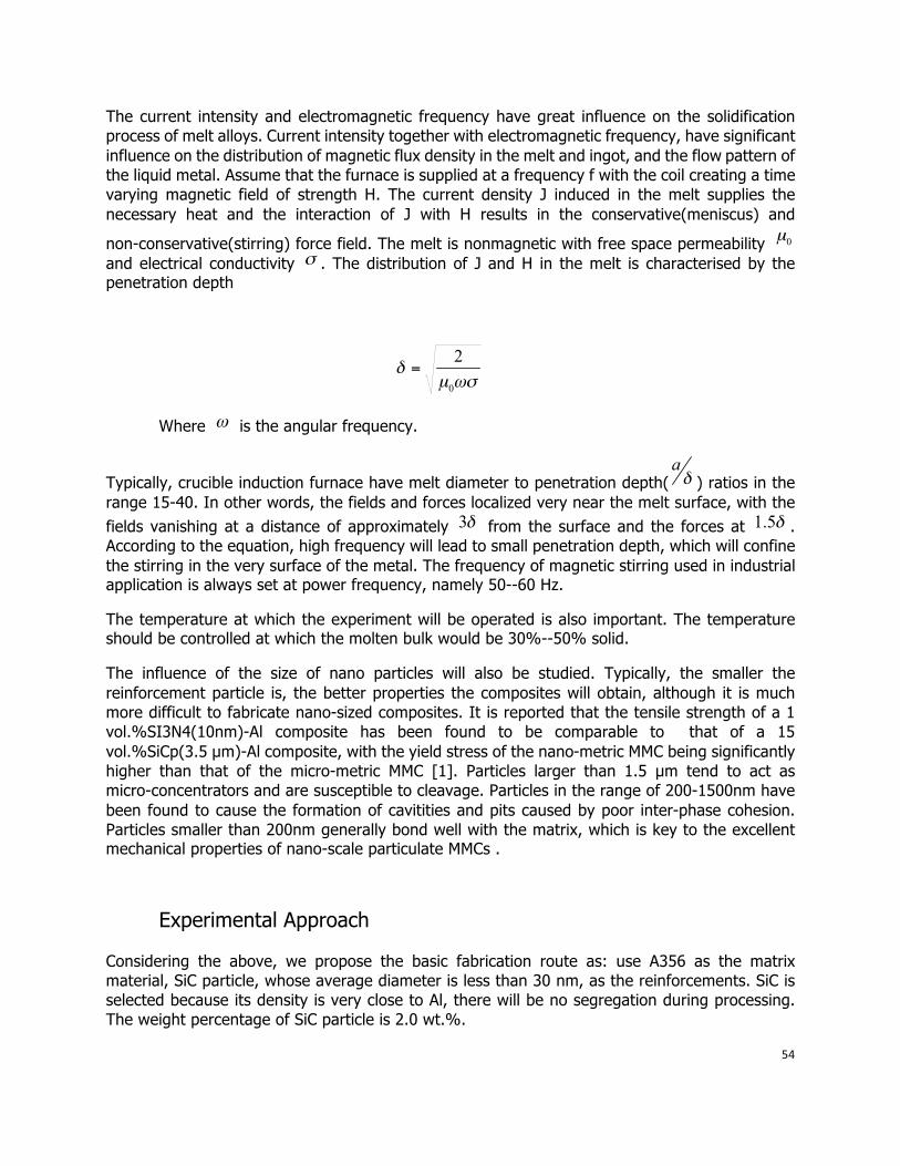
54
The current intensity and electromagnetic frequency have great influence on the solidification process of melt alloys. Current intensity together with electromagnetic frequency, have significant influence on the distribution of magnetic flux density in the melt and ingot, and the flow pattern of the liquid metal. Assume that the furnace is supplied at a frequency f with the coil creating a time varying magnetic field of strength H. The current density J induced in the melt supplies the necessary heat and the interaction of J with H results in the conservative(meniscus) and
non-conservative(stirring) force field. The melt is nonmagnetic with free space permeability and electrical conductivity . The distribution of J and H in the melt is characterised by the penetration depth
Where is the angular frequency.
Typically, crucible induction furnace have melt diameter to penetration depth( ) ratios in the range 15-40. In other words, the fields and forces localized very near the melt surface, with the fields vanishing at a distance of approximately from the surface and the forces at . According to the equation, high frequency will lead to small penetration depth, which will confine the stirring in the very surface of the metal. The frequency of magnetic stirring used in industrial application is always set at power frequency, namely 50--60 Hz.
The temperature at which the experiment will be operated is also important. The temperature should be controlled at which the molten bulk would be 30%--50% solid.
The influence of the size of nano particles will also be studied. Typically, the smaller the reinforcement particle is, the better properties the composites will obtain, although it is much more difficult to fabricate nano-sized composites. It is reported that the tensile strength of a 1 vol.%SI3N4(10nm)-Al composite has been found to be comparable to that of a 15 vol.%SiCp(3.5 µm)-Al composite, with the yield stress of the nano-metric MMC being significantly higher than that of the micro-metric MMC [1]. Particles larger than 1.5 µm tend to act as micro-concentrators and are susceptible to cleavage. Particles in the range of 200-1500nm have been found to cause the formation of cavitities and pits caused by poor inter-phase cohesion. Particles smaller than 200nm generally bond well with the matrix, which is key to the excellent mechanical properties of nano-scale particulate MMCs .
Experimental Approach
Considering the above, we propose the basic fabrication route as: use A356 as the matrix material, SiC particle, whose average diameter is less than 30 nm, as the reinforcements. SiC is selected because its density is very close to Al, there will be no segregation during processing. The weight percentage of SiC particle is 2.0 wt.%.
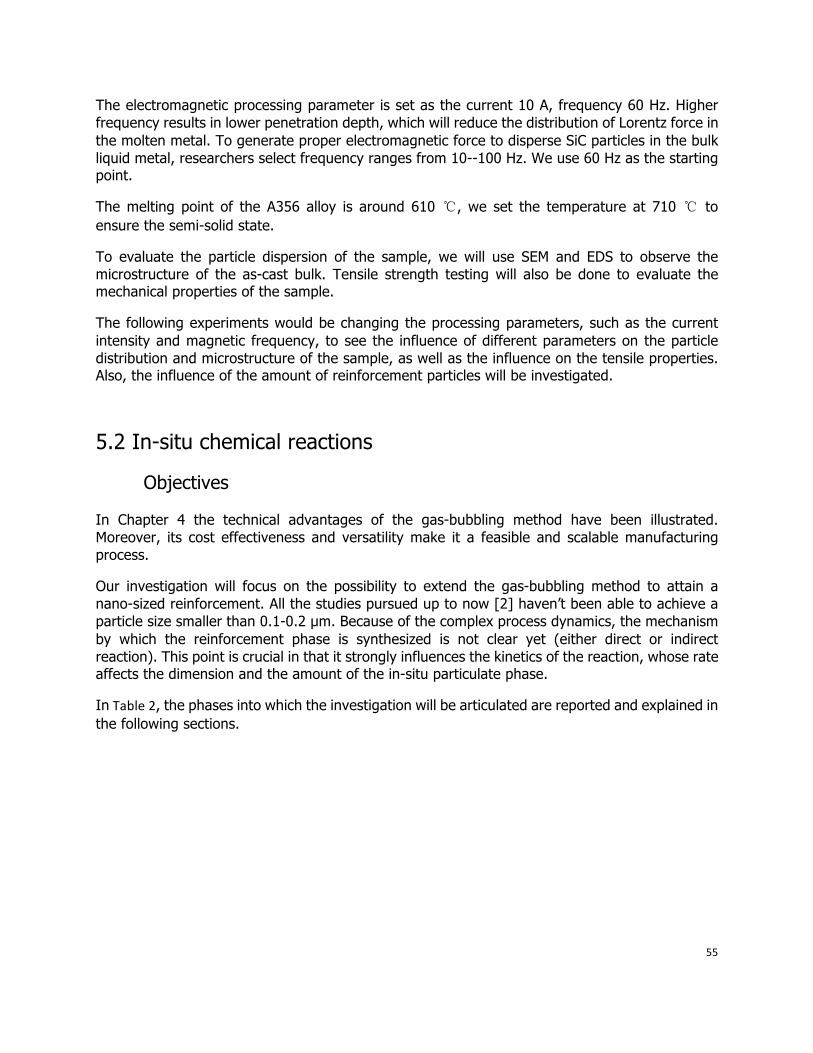
55
The electromagnetic processing parameter is set as the current 10 A, frequency 60 Hz. Higher frequency results in lower penetration depth, which will reduce the distribution of Lorentz force in the molten metal. To generate proper electromagnetic force to disperse SiC particles in the bulk liquid metal, researchers select frequency ranges from 10--100 Hz. We use 60 Hz as the starting point.
The melting point of the A356 alloy is around 610 ℃, we set the temperature at 710 ℃ to ensure the semi-solid state.
To evaluate the particle dispersion of the sample, we will use SEM and EDS to observe the microstructure of the as-cast bulk. Tensile strength testing will also be done to evaluate the mechanical properties of the sample.
The following experiments would be changing the processing parameters, such as the current intensity and magnetic frequency, to see the influence of different parameters on the particle distribution and microstructure of the sample, as well as the influence on the tensile properties. Also, the influence of the amount of reinforcement particles will be investigated.
5.2 In-situ chemical reactions
Objectives
In Chapter 4 the technical advantages of the gas-bubbling method have been illustrated. Moreover, its cost effectiveness and versatility make it a feasible and scalable manufacturing process.
Our investigation will focus on the possibility to extend the gas-bubbling method to attain a nano-sized reinforcement. All the studies pursued up to now [2] haven’t been able to achieve a particle size smaller than 0.1-0.2 µm. Because of the complex process dynamics, the mechanism by which the reinforcement phase is synthesized is not clear yet (either direct or indirect reaction). This point is crucial in that it strongly influences the kinetics of the reaction, whose rate affects the dimension and the amount of the in-situ particulate phase.
InTable2, the phases into which the investigation will be articulated are reported and explained in the following sections.
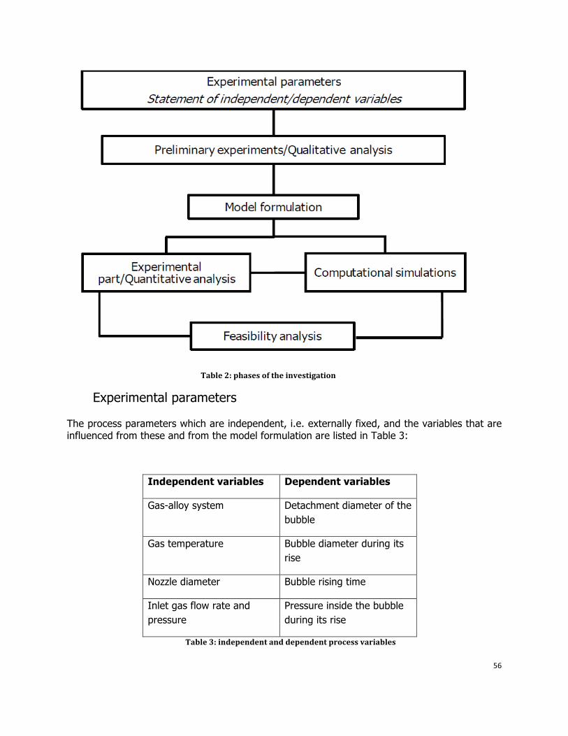
56
Table 2: phases of the investigation
Experimental parameters
The process parameters which are independent, i.e. externally fixed, and the variables that are influenced from these and from the model formulation are listed in Table 3:
Independent variables Dependent variables
Gas-alloy system Detachment diameter of the bubble
Gas temperature Bubble diameter during its rise
Nozzle diameter Bubble rising time
Inlet gas flow rate and pressure
Pressure inside the bubble during its rise
Table 3: independent and dependent process variables
57
In what follows, dependent variables are discussed in the prespective of their influence on reinforcement size.
Dependent variables
Detachment diameter of the bubble ( )
The diameter that characterizes the bubble when it detaches from the nozzle can be listed as semi-dependent variable, in the sense that it is directly derived from the parameters that have been fixed for the system. Moreover, it affects the bubble rising time (Figure 32) and terminal velocity. Madhavi et al. [3] found that the rising velocity of initially larger bubbles were found to be higher as well as the Enhancement Factor, which describes the enhancement of the mass transfer coefficient in the presence of a chemical reaction in the liquid bulk as in this case. The gas-liquid mass flow is fundamental in the sense that it determines the amount of the reinforcement phase formed and the particle size (see next section).
Szekely [4] stated that depends on the gas flow rates and specifically:
• For high flow rates (Re > 2100) a jet is formed • For low flow rates (Re < 2100) bubbles are formed
where Re is the Reynold number of the gas injected in the metal. This statement imposes a constraint to the independent variables, since Re must remain below 2100 for the bubbles to occur. The detachment bubble diameter is straightforward calculated for low gas flow rates (Re<500) from the balance between the buoyancy force, that tends to detach the bubble from the nozzle and the tension coming from the forming surface (surface tension). For higher
Reynolds numbers (500<Re<1200) is smaller, since the turbulence enhances the tendency of the bubble to detach from the nozzle. Similar relations have been attained in other works [5] where the initial bubble size is defined as independent from the properties of the liquid and only as a function of the nozzle diameter and the gas velocity.
58
Figure 32: bubble resident time versus initial radius for different mass concentration in the liquid melt [6]
Bubble diameter during its rise ( ) and rising time (t)
The rising time of the bubble determines how long the bubble stays into the melt and can be able to react with the melt itself to synthesize the reinforcement.The time is strictly bonded to the velocity by which the bubble rise into the melt. Most of the studies concerning bubble motion in a liquid [2,4] calculate the terminal velocity of the bubble in case of no-mass transfer or chemical reaction. The terminal velocity is the velocity at which the drag force and the buoyancy are equal and thus the bubble is not accelerated during the rise. Szekely [4] expressed the terminal bubble velocity of a small spheric bubble according to Stoke’s law for a bubble of unchanged diameter and thus, unchanged volume.
Instead, the bubble diameter changes during its rise, for mainly two reasons:
• The pressure decreases as the bubble rises to the top because of the reduction of the metallostatic head according to the formula:
+
Where is the bubble pressure, the atmospheric pressure, is the bubble surface tension, R the gas-bubble radius and h the metallostatic head, i.e. the depth at which the bubble is located.This pressure reduction causes the bubble to expand during its rise and the velocity, which is directly proportioal to it, should also increase [4,5,6].
• Gas –liquid mass transfer leads to a decrease in the bubble mass and thus, in the bubble volume for a given pressure. For this reason, the bubble tends to slow down as the rising time passes by and the mass transfer continues to occur. As a consequence, the resident
59
time of the bubble in the melt is higher as well as the amount of reinforcement synthesized in the melt. Figure33shows the bubble radius diminishing with time until the complete collapse of the bubble itself [7]. The change in the bubble volume (and thus in the radius) can be correlated to the mass flux density into the liquid according to the equation [6]:
4
where is the gas density, the volume of the gas bubble, R the bubble radius and the mass flux density. By expressing the mass flux density with respect to time, the bubble radius dependence on time and the bubble residence time can be calculated [6].
Figure 33: bubble mass and diameter versus time [7]
Experimental part and computational simulations
The experimental part will be divided into two phases:
1. Preliminary trials
Some experiments will be led at the beginning of the investigation in order to validate the results reported in the literature (Chapter 4) and to set the background for future experiments that will be specifically devoted to achieve a nano-sized reinforcement.
Moreover, this part will be useful to verify the most suitable experimental lay-out. Specifically the same lay-out adopted in the literature (Chapter 4) will be employed during this phase, i.e. an impeller will be submerged in the melt and the gas injected from above (Figure34).
The proposed independent parameters are:
60
• Gas: nitrogen bearing gas with inert gas added (90 % N₂ or NH₃, 10% Argon) • Alloy system: pure aluminum + refractory material (Al-Ti, Al-Zr,Al-Ta) • Gas temperature: 1000 K • Gas flow rate: around 0.4 L/min
Figure 34: sketch of the experimental setup for the preliminary trials
2. Main experimental part and computational simulations
The experiments that will be carried out will have the following objectives:
• Define a DOE (Design of Experiment) that can be successfully employed to attain a reinforcement size in the nano-scale dimension. Specifically, the model formulation will interact with the experiments in determine what are the variables that influence the reinforcement size (see next section)
• Testing other experimental set-ups
Numerical simulations in COMSOL will be integrated with the experimental part to validate the model and to simulate the gas-bubble motion in the melt and the change in bubble diameter connected with particle growth. The principle assumptions that will be employed for the simulations are:
• The bubble shape is spherical from formation to dissolution • The surface tension of the bubble is equal on each side of the bubble
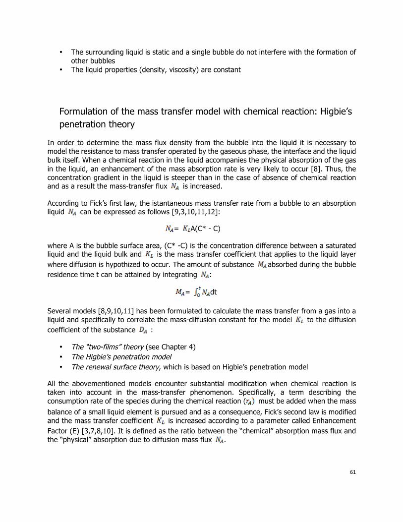
61
• The surrounding liquid is static and a single bubble do not interfere with the formation of other bubbles
• The liquid properties (density, viscosity) are constant
Formulation of the mass transfer model with chemical reaction: Higbie’s penetration theory
In order to determine the mass flux density from the bubble into the liquid it is necessary to model the resistance to mass transfer operated by the gaseous phase, the interface and the liquid bulk itself. When a chemical reaction in the liquid accompanies the physical absorption of the gas in the liquid, an enhancement of the mass absorption rate is very likely to occur [8]. Thus, the concentration gradient in the liquid is steeper than in the case of absence of chemical reaction and as a result the mass-transfer flux is increased.
According to Fick’s first law, the istantaneous mass transfer rate from a bubble to an absorption liquid can be expressed as follows [9,3,10,11,12]:
= A(C* - C)
where A is the bubble surface area, (C* -C) is the concentration difference between a saturated liquid and the liquid bulk and is the mass transfer coefficient that applies to the liquid layer where diffusion is hypothized to occur. The amount of substance absorbed during the bubble residence time t can be attained by integrating :
= dt
Several models [8,9,10,11] has been formulated to calculate the mass transfer from a gas into a liquid and specifically to correlate the mass-diffusion constant for the model to the diffusion coefficient of the substance :
• The “two-films” theory (see Chapter 4) • The Higbie’s penetration model • The renewal surface theory, which is based on Higbie’s penetration model
All the abovementioned models encounter substantial modification when chemical reaction is taken into account in the mass-transfer phenomenon. Specifically, a term describing the consumption rate of the species during the chemical reaction ( must be added when the mass balance of a small liquid element is pursued and as a consequence, Fick’s second law is modified and the mass transfer coefficient is increased according to a parameter called Enhancement Factor (E) [3,7,8,10]. It is defined as the ratio between the “chemical” absorption mass flux and the “physical” absorption due to diffusion mass flux .
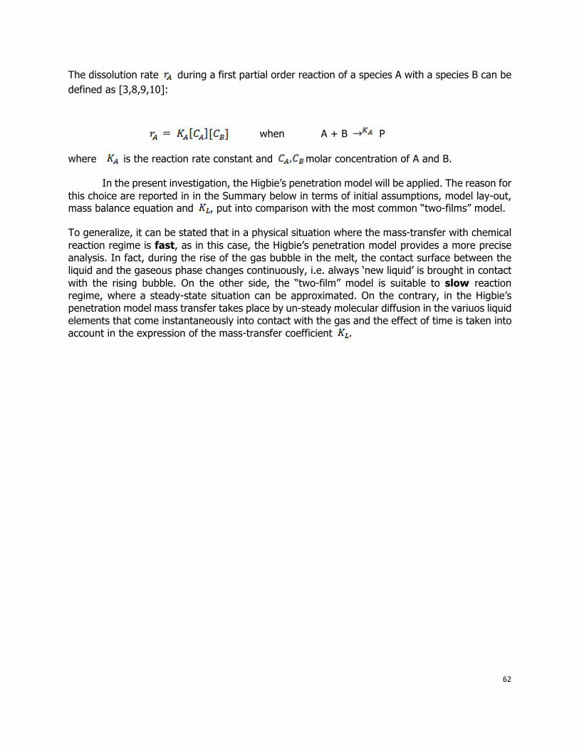
62
The dissolution rate during a first partial order reaction of a species A with a species B can be defined as [3,8,9,10]:
when A + B P
where is the reaction rate constant and molar concentration of A and B.
In the present investigation, the Higbie’s penetration model will be applied. The reason for this choice are reported in in the Summary below in terms of initial assumptions, model lay-out, mass balance equation and , put into comparison with the most common “two-films” model.
To generalize, it can be stated that in a physical situation where the mass-transfer with chemical reaction regime is fast, as in this case, the Higbie’s penetration model provides a more precise analysis. In fact, during the rise of the gas bubble in the melt, the contact surface between the liquid and the gaseous phase changes continuously, i.e. always ‘new liquid’ is brought in contact with the rising bubble. On the other side, the “two-film” model is suitable to slow reaction regime, where a steady-state situation can be approximated. On the contrary, in the Higbie’s penetration model mass transfer takes place by un-steady molecular diffusion in the variuos liquid elements that come instantaneously into contact with the gas and the effect of time is taken into account in the expression of the mass-transfer coefficient .
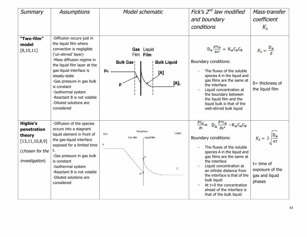
63
Summary Assumptions Model schematic Fick’s 2nd law modified and boundary conditions
Mass-transfer coefficient
“Two-film” model [8,10,11]
-Diffusion occurs just in the liquid film where convection is negligible (‘un-stirred’ layer) -Mass diffusion regime in the liquid film layer at the gas-liquid interface is steady-state -Gas pressure in gas bulk is constant -Isothermal system -Reactant B is not volatile -Diluted solutions are considered
=
Boundary conditions:
- The fluxes of the soluble species A in the liquid and gas films are the same at the interface
- Liquid concentration at the boundary between the liquid film and the liquid bulk is that of the well-stirred bulk liquid
δ= thickness of the liquid film
Higbie’s penetration theory [13,11,10,8,9]
(chosen for the
investigation)
-Diffusion of the species occurs into a stagnant liquid element in front of the gas-liquid interface exposed for a limited time t. -Gas pressure in gas bulk is constant -Isothermal system -Reactant B is not volatile -Diluted solutions are considered
=
Boundary conditions:
- The fluxes of the soluble species A in the liquid and gas films are the same at the interface
- Liquid concentration at an infinite distance from the interface is that of the bulk liquid
- At t=0 the concentration ahead of the interface is that of the bulk liquid
t= time of exposure of the gas and liquid phases