Embed Size (px)
Citation preview
Aalborg Universitet
DC Microgrids – Part I
Dragicevic, Tomislav; Lu, Xiaonan; Quintero, Juan Carlos Vasquez; Guerrero, Josep M.
Published in:I E E E Transactions on Power Electronics
DOI (link to publication from Publisher):10.1109/TPEL.2015.2478859
Publication date:2016
Document VersionEarly version, also known as pre-print
Link to publication from Aalborg University
Citation for published version (APA):Dragicevic, T., Lu, X., Quintero, J. C. V., & Guerrero, J. M. (2016). DC Microgrids – Part I: A Review of ControlStrategies and Stabilization Techniques. I E E E Transactions on Power Electronics, 31(7), 4876 - 4891. DOI:10.1109/TPEL.2015.2478859
General rightsCopyright and moral rights for the publications made accessible in the public portal are retained by the authors and/or other copyright ownersand it is a condition of accessing publications that users recognise and abide by the legal requirements associated with these rights.
? Users may download and print one copy of any publication from the public portal for the purpose of private study or research. ? You may not further distribute the material or use it for any profit-making activity or commercial gain ? You may freely distribute the URL identifying the publication in the public portal ?
Take down policyIf you believe that this document breaches copyright please contact us at [email protected] providing details, and we will remove access tothe work immediately and investigate your claim.
Downloaded from vbn.aau.dk on: juni 07, 2018
Abstract - This paper presents a review of control strategies,
stability analysis and stabilization techniques for DC microgrids
(MGs). Overall control is systematically classified into local and
coordinated control levels according to respective functionalities
in each level. As opposed to local control which relies only on
local measurements, some line of communication between units
needs to be made available in order to achieve coordinated
control. Depending on the communication method, three basic
coordinated control strategies can be distinguished, i.e.
decentralized, centralized and distributed control. Decentralized
control can be regarded as an extension of local control since it is
also based exclusively on local measurements. In contrast,
centralized and distributed control strategies rely on digital
communication technologies. A number of approaches to using
these three coordinated control strategies to achieve various
control objectives are reviewed in the paper. Moreover,
properties of DC MG dynamics and stability are discussed. The
paper illustrates that tightly regulated point-of-load (POL)
converters tend to reduce the stability margins of the system since
they introduce negative impedances, which can potentially
oscillate with lightly damped power supply input filters. It is also
demonstrated how the stability of the whole system is defined by
the relationship of the source and load impedances, referred to as
the minor loop gain. Several prominent specifications for the
minor loop gain are reviewed. Finally, a number of active
stabilization techniques are presented.
Index Terms - DC microgrid (MG), local control, coordinated
control, impedance specifications, stability.
NOMENCLATURE
Acronyms
AVP Adaptive voltage positioning.
BLDC Brushless DC.
CC Central controller.
CPL Constant power load.
DBS DC bus signaling.
DCL Digital communication link.
DG Distributed generator.
DPS Distributed power system.
EET Extra element theorem.
ESAC Energy storage analysis consortium.
ESS Energy storage system.
EV Electric vehicle.
GM Gain margin.
Tomislav Dragičević, Juan C. Vasquez, and Josep M. Guerrero are with
Department of Energy Technology, Aalborg University, Denmark (email:
[email protected], [email protected], [email protected]).
Xiaonan Lu is with Energy Systems Division, Argonne National
Laboratory, Lemont, IL, USA (email: [email protected]).
GMPM Gain margin and phase margin.
LC Local controller.
MG Microgrid.
MPPT Maximum power point tracking.
OA Opposing argument.
PCC Point of common coupling.
PD Proportional-derivative.
PI Proportional-integral.
PLC Power line communication.
PLS Power line signaling.
PM Phase margin.
POL Point of load.
PR Proportional-resonant.
PV Photovoltaics.
RES Renewable energy source.
RHP Right-half plane.
TF Transfer function.
VR Virtual resistance.
Variables and Operators
bi(t) Input bias of node #i.
C POL converter filter capacitor.
D POL converter steady state duty cycle.
Gc(s) Transfer function of the voltage controller.
Gvd(s) Transfer function describing the relation
between converter duty ratio and output
voltage.
Gvg(s) Transfer function describing the relation
between line disturbance and output voltage.
Gvd,filt(s) Transfer function describing the relation
between converter duty ratio and output voltage
after the application of input filter.
H(s) Voltage sensor gain.
iPOL Input current of the POL converter.
iload Output current of the POL converter.
L POL converter inductance.
mp, mc Droop coefficients with power or current
feedback.
Ni Set of nodes adjacent to node #i.
Poi Output power of converter #i.
ioi Output current of converter #i.
P DC load power.
Ploadi Output power of POL converter #i.
Psource Source power.
R Load resistance.
Rinc POL converter incremental resistance.
DC Microgrids–Part I: A Review of Control
Strategies and Stabilization Techniques Tomislav Dragičević, Member, IEEE, Xiaonan Lu, Member, IEEE, Juan C. Vasquez, Senior Member,
IEEE and Josep M. Guerrero, Fellow, IEEE
RL Series resistance of the filter inductor.
SoC State of charge.
s Laplace operator.
T(s) Loop gain of the POL converter control loop.
TMLG(s) Minor loop gain.
vDCi* DC link voltage reference value of converter #i.
vDC* Nominal DC link voltage.
vDC DC link voltage.
vref Reference value of the load voltage.
vs DC source voltage.
vload Load voltage.
1/Vm PWM gain.
xi(t) Variable of interest in node #i used in
consensus algorithm.
ZN(s) Input impedance of the POL converter if
control loop operates ideally (closed loop input
impedance in low frequency region).
ZD(s) Input impedance of the POL converter without
control loop (open loop input impedance).
Zin(s) Closed loop input impedance of the POL
converter in the whole frequency region.
Zout(s) Open loop output impedance of the POL
converter.
Zs(s) Output impedance of the source.
Θ Graph Laplacian of the communication
network.
θij Elements of Θ.
I. INTRODUCTION
nvironmental concerns and reduction of fossil fuel
reserves gave rise to a growing increase in the
penetration of distributed generators (DGs) that include
renewable energy sources (RESes), energy storage systems
(ESSes) and new types of loads like electric vehicles (EVs)
and heat pumps in the modern power systems. However, these
new components may pose many technical and operational
challenges should they continue to be integrated in an
uncoordinated way, as is the case today. Appearing in large
numbers and scattered across the large geographical areas of
interconnected networks, some of the most prominent
problems that they can introduce in the system’s operating
conditions include deteriorated voltage profile, congestions in
transmission lines and reduction of frequency reserves [1].
The idea of merging small variable nature sources with
ESSes and controllable loads into flexible entities that are
called microgrids (MGs) has been presented more than a
decade ago [2], as a possible solution to achieve more
traceable control from the system point of view. MGs can
operate autonomously or be grid-connected and, depending on
the type of voltage in the point of common coupling (PCC),
AC and DC MGs can be distinguished [3]. While remarkable
progress has been made in improving the performance of AC
MGs during the past decade [4]–[11], DC MGs have been
recognized as more attractive for numerous uses due to higher
efficiency, more natural interface to many types of RES and
ESS, better compliance with consumer electronics, etc. [12].
Besides, when components are coupled around a DC bus, there
are no issues with reactive power flow, power quality and
frequency regulation, resulting in a notably less complex
control system [13]–[18].
DGs are connected to a DC MG almost exclusively through
a controllable power electronic interface converters and
regulation of the common DC bus voltage is the main control
priority. Droop control is a popular method of achieving this
by means of cooperative operation among paralleled
converters without digital communication links [17], [19]. The
method is based on adding a so-called virtual resistance (VR)
control loop on top of the converter’s voltage regulator which
allows current sharing, while providing active damping to the
system and plug and play capability at the same time [20], [21].
However, in spite of these attractive features, there are
several drawbacks that limit the applicability of droop in its
basic shape. The most important ones are load-dependent
voltage deviation and the fact that propagation of voltage error
along resistive transmission lines causes deterioration of
current sharing. A secondary controller needs to be
implemented in order to restore the voltage and tertiary
controller so as to ensure precise current flow among different
buses [12]. There are several options on how to implement this
controller. As for that, while the conventional approach uses a
centralized controller which collects information from all units
via low-bandwidth digital communication links (DCLs) [3], a
very active field of research is focused on resolution of these
problems via distributed control1 [22], [23]. As a way to
realize various distributed control strategies, the application of
consensus algorithms in DC MGs has recently emerged as a
popular and fashionable approach [22], [24], [25].
Another problem with the basic droop method is its
inability to achieve coordinated performance of multiple
components with different characteristics (i.e., ESSes, RESes,
utility mains, controllable loads etc.). In that case, either a
decentralized, centralized or distributed supervisory control
needs to be implemented on top of it to decide whether the unit
should operate in droop or some other specific control mode
such as maximum power point tracking (MPPT) [26], [27] or
regulated charging mode [28]. Except for setting operating
modes and managing secondary/tertiary control,
communication technology can also be used to realize
advanced functions such as unit commitment, optimization
procedures or manipulation of internal I-V characteristics by
imposing adaptive mechanisms [14], [28]–[30].
Along with precise voltage and current regulation, as well
as system level coordination, stable operation of the MG needs
to be ensured in all operating conditions. Tightly regulated
point of load (POL) converters present a challenge from that
point of view since they introduce a negative impedance
characteristic within the bandwidth of their control loops [31],
[32]. This peculiar feature reduces the effective damping and
can even cause instability of the entire system. The
1 The term “distributed control” refers to the situation where information is
exchanged through DCLs only between units, rather than between units and a
central aggregator.
E
relationship between source and load impedances, often
referred to as the minor loop gain, is an important quantity
which can be used for determining stability [31]. Different
specifications for the minor loop gain have been proposed not
only to ensure stability but also to maintain good system
dynamics after connecting additional elements such as input
filters [31], [33]–[39]. Modeling of the entire state space is an
alternative option which explicitly takes into account the
complete system but does not provide such a good insight into
dynamics as the impedance based approach. A variety of
passive and active stabilization techniques have been
developed using both methods in order to improve damping of
the system [40]–[44].
The aim of this article is to provide an overview of control
strategies, stability analysis tools and stabilization techniques
used in DC MGs. It is organized as follows. In Section II,
basic control principles are presented. It is demonstrated how
the overall converter control can be split into local and
coordinated controls. Section III explores in more depth a
number of functionalities within the local control, while
coordinated control is addressed in Section IV. A detailed
analysis of the stability problem is presented in Section V,
where it is shown how a dynamic model of the whole DC MG
system can be conveniently divided into a source and load
subsystems which are characterized by their respective
impedances. It is explained how the relationship of these
impedances defines the stability of the system, and several
prominent impedance specifications and stabilization
principles are reviewed. Concluding remarks and an overview
of future research trends can be found in Section VI.
II. DC MG CONTROL PRINCIPLES
In order to guarantee stable and efficient operation of a DC
MG, effective control strategies should be developed. The
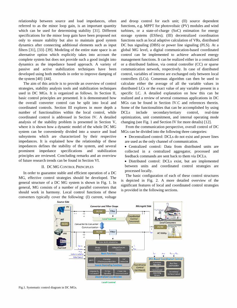
general structure of a DC MG system is shown in Fig. 1. In
general, MG consists of a number of parallel converters that
should work in harmony. Local control functions of these
converters typically cover the following: (I) current, voltage
and droop control for each unit; (II) source dependent
functions, e.g. MPPT for photovoltaic (PV) modules and wind
turbines, or a state-of-charge (SoC) estimation for energy
storage systems (ESSes); (III) decentralized coordination
functions such as local adaptive calculation of VRs, distributed
DC bus signaling (DBS) or power line signaling (PLS). At a
global MG level, a digital communication-based coordinated
control can be implemented to achieve advanced energy
management functions. It can be realized either in a centralized
or a distributed fashion, via central controller (CC) or sparse
communication network, respectively. In case of distributed
control, variables of interest are exchanged only between local
controllers (LCs). Consensus algorithm can then be used to
calculate either the average of all the variable values in
distributed LCs or the exact value of any variable present in a
specific LC. A detailed explanation on how this can be
realized and a review of several consensus applications in DC
MGs can be found in Section IV.C and references therein.
Some of the functionalities that can be accomplished by using
DCLs include secondary/tertiary control, real-time
optimization, unit commitment, and internal operating mode
changing (see Fig. 1 and Section IV for more details) [12].
From the communication perspective, overall control of DC
MGs can be divided into the following three categories:
Decentralized control: DCLs do not exist and power lines
are used as the only channel of communication.
Centralized control: Data from distributed units are
collected in a centralized aggregator, processed and
feedback commands are sent back to them via DCLs.
Distributed control: DCLs exist, but are implemented
between units and coordinated control strategies are
processed locally.
The basic configuration of each of these control structures
is depicted in Fig. 2. A more detailed overview of the
significant features of local and coordinated control strategies
is provided in the following sections.
Fig.1. Systematic control diagram in DC MGs.
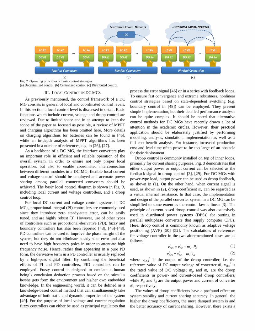
(a) (b) (c)
Fig. 2. Operating principles of basic control strategies.
(a) Decentralized control. (b) Centralized control. (c) Distributed control.
III. LOCAL CONTROL IN DC MGS
As previously mentioned, the control framework of a DC
MG consists in general of local and coordinated control levels.
In this section a local control level is discussed in detail. Basic
functions which include current, voltage and droop control are
reviewed. Due to limited space and in an attempt to keep the
scope of the paper as focused as possible, a review of MPPT
and charging algorithms has been omitted here. More details
on charging algorithms for batteries can be found in [45],
while an in-depth analysis of MPPT algorithms has been
presented in a number of references, e.g. in [26], [27].
As a backbone of a DC MG, the interface converters play
an important role in efficient and reliable operation of the
overall system. In order to ensure not only proper local
operation, but also to enable coordinated interconnection
between different modules in a DC MG, flexible local current
and voltage control should be employed and accurate power
sharing among parallel connected converters should be
achieved. The basic local control diagram is shown in Fig. 3,
including local current and voltage controllers, and a droop
control loop.
For local DC current and voltage control systems in DC
MGs, proportional-integral (PI) controllers are commonly used
since they introduce zero steady-state error, can be easily
tuned, and are highly robust [3]. However, use of other types
of controllers such as proportional-derivative (PD), fuzzy and
boundary controllers has also been reported [43], [46]–[48].
PD controllers can be used to improve the phase margin of the
system, but they do not eliminate steady-state error and also
need to have high frequency poles in order to attenuate high
frequency noise. Hence, rather than appearing in a pure PD
form, the derivative term in a PD controller is usually replaced
by a high-pass digital filter. By combining the beneficial
effects of PI and PD controllers, PID controllers can be
employed. Fuzzy control is designed to emulate a human
being’s conclusion deduction process based on the stimulus
he/she gets from the environment and his/her own embedded
knowledge. In the engineering world, it can be defined as a
knowledge-based control method that can simultaneously take
advantage of both static and dynamic properties of the system
[49]. For the purpose of local voltage and current regulation
fuzzy controllers can either be used as principal regulators that
process the error signal [46] or in a series with feedback loops.
To ensure fast convergence and extreme robustness, nonlinear
control strategies based on state-dependent switching (e.g.
boundary control in [48]) can be employed. They present
simple implementation, but their detailed performance analysis
can be quite complex. It should be noted that alternative
control methods for DC MGs have recently drawn a lot of
attention in the academic circles. However, their practical
application should be elaborately justified by performing
modeling, analysis, simulation, implementation as well as a
full cost-benefit analysis. For instance, increased production
cost and lead time often prove to be too large of an obstacle
for their deployment.
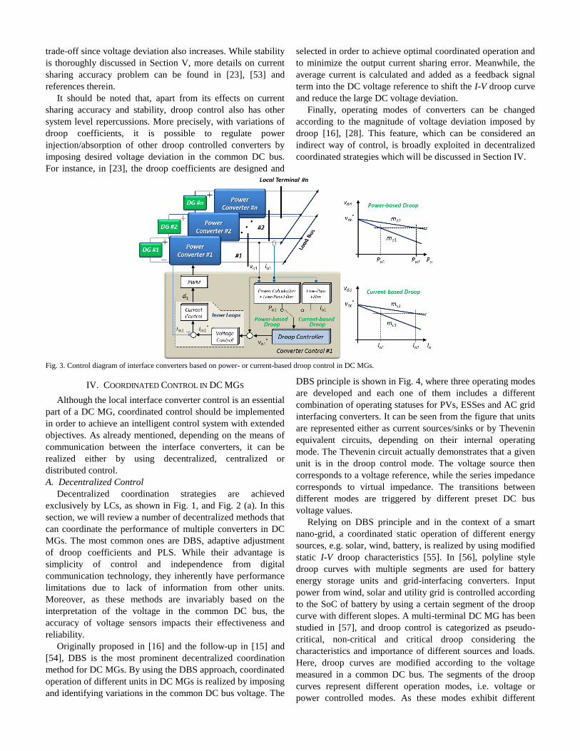
Droop control is commonly installed on top of inner loops,
primarily for current sharing purposes. Fig. 3 demonstrates that
either output power or output current can be selected as the
feedback signal in droop control [3], [29]. For DC MGs with
power-type load, output power can be used as droop feedback,
as shown in (1). On the other hand, when current signal is
used, as shown in (2), droop coefficient mc can be regarded as
a virtual internal resistance. In that case, the implementation
and design of the parallel converter system in a DC MG can be
simplified to some extent as the control law is linear [3]. The
principle of current-based droop control was also extensively
used in distributed power systems (DPSs) for putting in
parallel multiphase converters that supply computer CPUs.
Here, droop control is commonly known as adaptive voltage
positioning (AVP) [50]–[52]. The calculations of references
for voltage controller in the two aforementioned cases are as
follows: * *
DCi DC p oiv v m P (1)
* *
DCi DC c oiv v m i (2)
where vDCi* is the output of the droop controller, i.e. the
reference value of DC output voltage of converter #i, vDC* is
the rated value of DC voltage; mp and mc are the droop
coefficients in power- and current-based droop controllers,
while Poi and ioi are the output power and current of converter
#i, respectively.
The values of droop coefficients have a profound effect on
system stability and current sharing accuracy. In general, the
higher the droop coefficients, the more damped system is and
the better accuracy of current sharing. However, there exists a
trade-off since voltage deviation also increases. While stability
is thoroughly discussed in Section V, more details on current
sharing accuracy problem can be found in [23], [53] and
references therein.
It should be noted that, apart from its effects on current
sharing accuracy and stability, droop control also has other
system level repercussions. More precisely, with variations of
droop coefficients, it is possible to regulate power
injection/absorption of other droop controlled converters by
imposing desired voltage deviation in the common DC bus.
For instance, in [23], the droop coefficients are designed and
selected in order to achieve optimal coordinated operation and
to minimize the output current sharing error. Meanwhile, the
average current is calculated and added as a feedback signal
term into the DC voltage reference to shift the I-V droop curve
and reduce the large DC voltage deviation.
Finally, operating modes of converters can be changed
according to the magnitude of voltage deviation imposed by
droop [16], [28]. This feature, which can be considered an
indirect way of control, is broadly exploited in decentralized
coordinated strategies which will be discussed in Section IV.
Fig. 3. Control diagram of interface converters based on power- or current-based droop control in DC MGs.
IV. COORDINATED CONTROL IN DC MGS
Although the local interface converter control is an essential
part of a DC MG, coordinated control should be implemented
in order to achieve an intelligent control system with extended
objectives. As already mentioned, depending on the means of
communication between the interface converters, it can be
realized either by using decentralized, centralized or
distributed control.
A. Decentralized Control
Decentralized coordination strategies are achieved
exclusively by LCs, as shown in Fig. 1, and Fig. 2 (a). In this
section, we will review a number of decentralized methods that
can coordinate the performance of multiple converters in DC
MGs. The most common ones are DBS, adaptive adjustment
of droop coefficients and PLS. While their advantage is
simplicity of control and independence from digital
communication technology, they inherently have performance
limitations due to lack of information from other units.
Moreover, as these methods are invariably based on the
interpretation of the voltage in the common DC bus, the
accuracy of voltage sensors impacts their effectiveness and
reliability.
Originally proposed in [16] and the follow-up in [15] and
[54], DBS is the most prominent decentralized coordination
method for DC MGs. By using the DBS approach, coordinated
operation of different units in DC MGs is realized by imposing
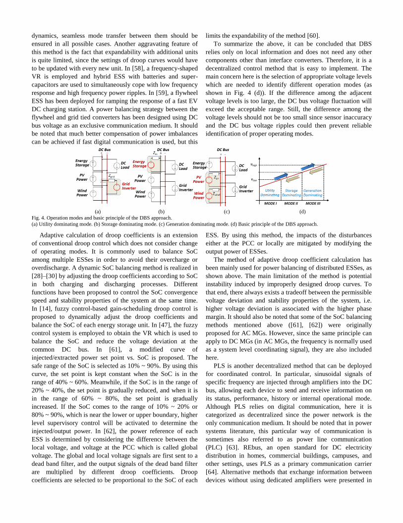
and identifying variations in the common DC bus voltage. The
DBS principle is shown in Fig. 4, where three operating modes
are developed and each one of them includes a different
combination of operating statuses for PVs, ESSes and AC grid
interfacing converters. It can be seen from the figure that units
are represented either as current sources/sinks or by Thevenin
equivalent circuits, depending on their internal operating
mode. The Thevenin circuit actually demonstrates that a given
unit is in the droop control mode. The voltage source then
corresponds to a voltage reference, while the series impedance
corresponds to virtual impedance. The transitions between
different modes are triggered by different preset DC bus
voltage values.
Relying on DBS principle and in the context of a smart
nano-grid, a coordinated static operation of different energy
sources, e.g. solar, wind, battery, is realized by using modified
static I-V droop characteristics [55]. In [56], polyline style
droop curves with multiple segments are used for battery
energy storage units and grid-interfacing converters. Input
power from wind, solar and utility grid is controlled according
to the SoC of battery by using a certain segment of the droop
curve with different slopes. A multi-terminal DC MG has been
studied in [57], and droop control is categorized as pseudo-
critical, non-critical and critical droop considering the
characteristics and importance of different sources and loads.
Here, droop curves are modified according to the voltage
measured in a common DC bus. The segments of the droop
curves represent different operation modes, i.e. voltage or
power controlled modes. As these modes exhibit different
dynamics, seamless mode transfer between them should be
ensured in all possible cases. Another aggravating feature of
this method is the fact that expandability with additional units
is quite limited, since the settings of droop curves would have
to be updated with every new unit. In [58], a frequency-shaped
VR is employed and hybrid ESS with batteries and super-
capacitors are used to simultaneously cope with low frequency
response and high frequency power ripples. In [59], a flywheel
ESS has been deployed for ramping the response of a fast EV
DC charging station. A power balancing strategy between the
flywheel and grid tied converters has been designed using DC
bus voltage as an exclusive communication medium. It should
be noted that much better compensation of power imbalances
can be achieved if fast digital communication is used, but this
limits the expandability of the method [60].
To summarize the above, it can be concluded that DBS
relies only on local information and does not need any other
components other than interface converters. Therefore, it is a
decentralized control method that is easy to implement. The
main concern here is the selection of appropriate voltage levels
which are needed to identify different operation modes (as
shown in Fig. 4 (d)). If the difference among the adjacent
voltage levels is too large, the DC bus voltage fluctuation will
exceed the acceptable range. Still, the difference among the
voltage levels should not be too small since sensor inaccuracy
and the DC bus voltage ripples could then prevent reliable
identification of proper operating modes.
(a) (b) (c) (d)
Fig. 4. Operation modes and basic principle of the DBS approach.
(a) Utility dominating mode. (b) Storage dominating mode. (c) Generation dominating mode. (d) Basic principle of the DBS approach.
Adaptive calculation of droop coefficients is an extension
of conventional droop control which does not consider change
of operating modes. It is commonly used to balance SoC
among multiple ESSes in order to avoid their overcharge or
overdischarge. A dynamic SoC balancing method is realized in
[28]–[30] by adjusting the droop coefficients according to SoC
in both charging and discharging processes. Different
functions have been proposed to control the SoC convergence
speed and stability properties of the system at the same time.
In [14], fuzzy control-based gain-scheduling droop control is
proposed to dynamically adjust the droop coefficients and
balance the SoC of each energy storage unit. In [47], the fuzzy
control system is employed to obtain the VR which is used to
balance the SoC and reduce the voltage deviation at the
common DC bus. In [61], a modified curve of
injected/extracted power set point vs. SoC is proposed. The
safe range of the SoC is selected as 10% ~ 90%. By using this
curve, the set point is kept constant when the SoC is in the
range of 40% ~ 60%. Meanwhile, if the SoC is in the range of
20% ~ 40%, the set point is gradually reduced, and when it is
in the range of 60% ~ 80%, the set point is gradually
increased. If the SoC comes to the range of 10% ~ 20% or
80% ~ 90%, which is near the lower or upper boundary, higher
level supervisory control will be activated to determine the
injected/output power. In [62], the power reference of each
ESS is determined by considering the difference between the
local voltage, and voltage at the PCC which is called global
voltage. The global and local voltage signals are first sent to a
dead band filter, and the output signals of the dead band filter
are multiplied by different droop coefficients. Droop
coefficients are selected to be proportional to the SoC of each
ESS. By using this method, the impacts of the disturbances
either at the PCC or locally are mitigated by modifying the
output power of ESSes.
The method of adaptive droop coefficient calculation has
been mainly used for power balancing of distributed ESSes, as
shown above. The main limitation of the method is potential
instability induced by improperly designed droop curves. To
that end, there always exists a tradeoff between the permissible
voltage deviation and stability properties of the system, i.e.
higher voltage deviation is associated with the higher phase
margin. It should also be noted that some of the SoC balancing
methods mentioned above ([61], [62]) were originally
proposed for AC MGs. However, since the same principle can
apply to DC MGs (in AC MGs, the frequency is normally used
as a system level coordinating signal), they are also included
here.
PLS is another decentralized method that can be deployed
for coordinated control. In particular, sinusoidal signals of
specific frequency are injected through amplifiers into the DC
bus, allowing each device to send and receive information on
its status, performance, history or internal operational mode.
Although PLS relies on digital communication, here it is
categorized as decentralized since the power network is the
only communication medium. It should be noted that in power
systems literature, this particular way of communication is
sometimes also referred to as power line communication
(PLC) [63]. REbus, an open standard for DC electricity
distribution in homes, commercial buildings, campuses, and
other settings, uses PLS as a primary communication carrier
[64]. Alternative methods that exchange information between
devices without using dedicated amplifiers were presented in
[65], [66]. Signals are generated by PWM of DC–DC
converters in those works. They are injected in open loop in
[66], whereas dedicated proportional-resonant (PR) controllers
are used during injection periods in [65] to avoid the steady-
state error in the DC bus.
In general, PLS is more complex to implement compared to
other decentralized methods such as DBS and adaptive droop.
Moreover, it is commonly used only for changing operating
modes or shutting corrupted components of the system, and it
is not suitable for power sharing. However, as opposed to
permanent voltage deviation in the common DC bus which is
inherent for DBS and adaptive droop methods, sinusoidal
signals are only periodically injected into the system.
Therefore, the quality of the voltage waveform can be
considered to some extent improved compared to other
methods.
B. Centralized Control
Centralized control can be implemented in DC MGs by
employing a central controller and a digital communication
network to connect it with sources and loads, as shown in the
DCL-based coordination control window of Fig. 1 and in Fig.
2 (b). For small scale DC MGs, each unit can be directly
controlled by the central controller that employs a high
bandwidth communication using a master/slave approach [67],
[68]. However, for larger scale DC MGs, hierarchical control
is often a preferred choice since it introduces a certain degree
of independence between different control levels. It is more
reliable as it continues to be operational even in case of failure
of centralized control. Hierarchical control is achieved by
simultaneously using local converter control and DCL-based
coordinated control, which are separated by at least an order of
magnitude in control bandwidth [3]. Coordinated functions can
include secondary/tertiary regulation of DC voltage, power
flow control and different grid-interactive control objectives
such as unit commitment, changing operating modes, global
optimization aimed at maximizing efficiency, minimizing
operating cost etc.
A centralized supervision control system is proposed in
[13] in order to realize an adaptive operation of a DC MG-
based data center. Eight operation modes are included in the
control scheme and features of twenty-three transitions among
them have been studied. In [69], a coordinated supervision
control diagram for DC sustainable building comprised of PV
arrays and EV chargers is proposed. The availability of the
RESes and the real-time customer demands have been
identified and the optimal decisions are made based on the
requirement of minimizing the operating cost. In [70], a
hierarchical control system is deployed for a campus
microgrid, and it is discussed how it can enhance the
coordinated and optimal operation of on-site generation in
relation to an AC based system. In [71], a hierarchical control
system is proposed for reliable and economical operation of
standalone DC MGs. DC bus regulation and prioritizations for
charging or discharging of batteries with a different SoC are
analyzed. Meanwhile, load shedding for extreme operating
conditions is studied. In [72], a hierarchical control diagram is
employed on the interface converters between AC and DC
buses and rectifier operation with AC to DC power flow is
studied. The control objectives for local AC and DC voltages
are achieved. At the same time, PCC voltage is restored in the
secondary control level, and power exchange between the local
DC MG and an external DC MG is realized in the tertiary
control level. In [73], a multi-layer supervision system is
proposed focused on power balancing, load shedding and
constrained PV production with an aim of building an
integrated system with PV and a battery. In [28], adaptive
voltage droop control is proposed in the primary control level
to balance the SoC. Meanwhile, a supervision control scheme
in the higher level is developed to determine the transitions of
different operation modes and to ensure coordinated
recharging of multiple battery banks within the DC MG.
Besides the control of a single DC MG, hierarchical control
diagram can also be used for multiple DC MG clusters. In
[74], a hierarchical control diagram with three control layers is
employed not only to achieve the control objectives of the
local MG, but also to optimize power distribution between
different MG clusters.
It should be noted that centralized control provides the best
foundation for employment of advanced control functionalities
since all relevant data can be collected and processed in a
single controller. However, the most obvious disadvantage of
this strategy is that it has a single point of failure. In particular,
if the central controller or any key communication link fails,
the commands from/to the controller will not be transmitted
and corresponding control objectives will likely not be
achieved. For mission critical applications, redundant
communication systems can be installed in order to reduce the
possibility of failure, but this needs to be justified by a cost-
benefit analysis. Another option to increase the reliability of
the system is to combine decentralized and centralized control
methods into a hierarchical control structure [28], [70]–[74].
In that case, basic functions of DC MGs can be retained even
if the centralized controller fails.
C. Distributed Control
Distributed control indicates the control principle where
central control unit does not exist and LCs communicate only
among themselves through dedicated DCLs, as shown in Fig. 2
(c). The main advantage of this approach is that the system can
maintain full functionality, even if the failure of some
communication links occurs, provided that communication
network remains connected2. Therefore, distributed control is
immune to single point of failure. The functionalities that can
be achieved by this approach resemble those of centralized
control and are also represented in the DCL-based
coordination control window of Fig. 1.
However, in order to enable these functionalities, the
information exchanged through DCLs first needs to be
appropriately processed. In particular, information directly
exchanged between LCs can contain only locally available
2 For the exact definition and a more in-depth discussion of the
connectivity of communication networks, please refer to [76].
variables. In other words, if the two units are not connected by
a DCL, they do not have direct access to each other’s data and
their observation of the system is quite limited. In order to
circumvent this problem and to make the level of awareness of
an LC similar to that of a CC, a consensus algorithm can be
used. In its basic form, a consensus algorithm is a simple
protocol installed within every LC which continuously adds up
all algebraic differences of some variable(s) of interest present
in a given LC and those present in LCs adjacent to it. If we
look at LC #i, this definition can also be expressed by the
following equation:
i
i i j i( ) [ ( ) ( )] ( )j N
x t x t x t b t
(3)
where xi(t) and xj(t) are the values of variables of interest in LC
#i and LC #j, respectively. Here, j is iterated through the whole
set of neighbors of LC #i, which is represented by Ni. Finally,
bi(t) is an optional input bias of LC, which can be used to
declare it as a virtual leader. It can be seen from (3) that xi(t) is
interactively adapted with respect to the values of its
neighboring units. Likewise, variables in any other controller
adapt with respect to the values of their own neighbors.
Consequently, it can be analytically proved that, if the
communication network is connected, all variable values will
converge to a common average after a certain amount of time
[75], [76]. Another option is to use a non-zero input bias in
one of the LCs. In that case, variables of all other LCs will
converge to his respective bias [77]. In either case, the ability
of consensus to share information in such a manner has wider
applicability than simple data averaging. For instance, if every
LC has information on the number of other active LCs, an
exact value of any specific variable can be calculated directly
from the average.
The collective dynamics of communication system realized
via consensus protocol can be represented by the following
equation:
( ) ( )x t x t (4)
where Θ = [θij] is the graph Laplacian of the network whose
elements are defined as follows:
i
ij
i
1
j N
N j i
(5)
where |Ni| denotes the number of neighbors of node #i. The
topology of communication network is explicitly reflected by
graph Laplacian and it is also possible to design weights of the
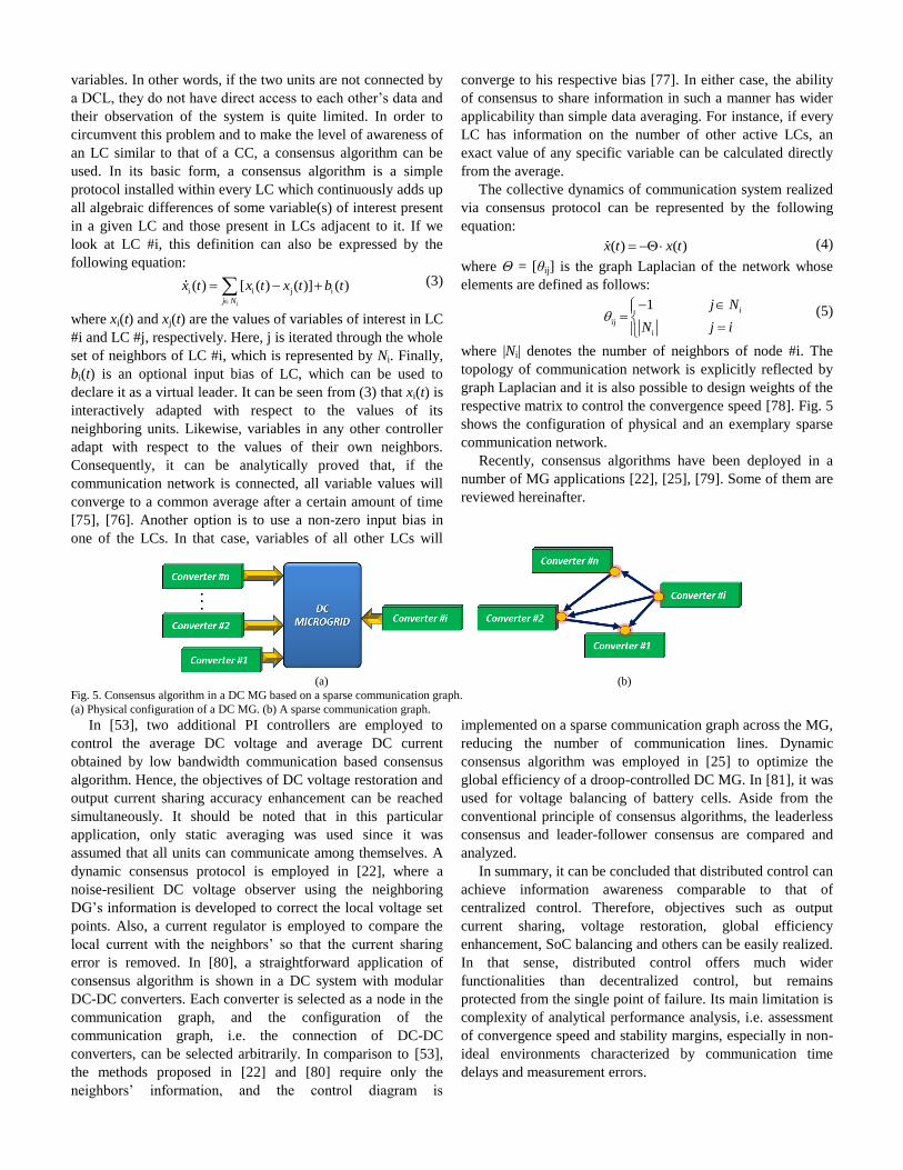
respective matrix to control the convergence speed [78]. Fig. 5
shows the configuration of physical and an exemplary sparse
communication network.
Recently, consensus algorithms have been deployed in a
number of MG applications [22], [25], [79]. Some of them are
reviewed hereinafter.
(a) (b)
Fig. 5. Consensus algorithm in a DC MG based on a sparse communication graph.
(a) Physical configuration of a DC MG. (b) A sparse communication graph.
In [53], two additional PI controllers are employed to
control the average DC voltage and average DC current
obtained by low bandwidth communication based consensus
algorithm. Hence, the objectives of DC voltage restoration and
output current sharing accuracy enhancement can be reached
simultaneously. It should be noted that in this particular
application, only static averaging was used since it was
assumed that all units can communicate among themselves. A
dynamic consensus protocol is employed in [22], where a
noise-resilient DC voltage observer using the neighboring
DG’s information is developed to correct the local voltage set
points. Also, a current regulator is employed to compare the
local current with the neighbors’ so that the current sharing
error is removed. In [80], a straightforward application of
consensus algorithm is shown in a DC system with modular
DC-DC converters. Each converter is selected as a node in the
communication graph, and the configuration of the
communication graph, i.e. the connection of DC-DC
converters, can be selected arbitrarily. In comparison to [53],
the methods proposed in [22] and [80] require only the
neighbors’ information, and the control diagram is
implemented on a sparse communication graph across the MG,
reducing the number of communication lines. Dynamic
consensus algorithm was employed in [25] to optimize the
global efficiency of a droop-controlled DC MG. In [81], it was
used for voltage balancing of battery cells. Aside from the
conventional principle of consensus algorithms, the leaderless
consensus and leader-follower consensus are compared and
analyzed.
In summary, it can be concluded that distributed control can
achieve information awareness comparable to that of
centralized control. Therefore, objectives such as output
current sharing, voltage restoration, global efficiency
enhancement, SoC balancing and others can be easily realized.
In that sense, distributed control offers much wider
functionalities than decentralized control, but remains
protected from the single point of failure. Its main limitation is
complexity of analytical performance analysis, i.e. assessment
of convergence speed and stability margins, especially in non-
ideal environments characterized by communication time
delays and measurement errors.
V. STABILITY ANALYSIS AND STABILIZATION METHODS FOR
DC MGS
In order to achieve safe and reliable MG performance, its
dynamic stability needs to be ensured in all operating
conditions. A typical cause of instability in DC MGs is
impedance mismatch between lightly damped filters on the
source side and tightly regulated power converters on the load
side. These kinds of converters, often referred to as the
constant power loads (CPLs), introduce a negative impedance
characteristic in low frequency range that tends to oscillate
with the output impedance of power supply filter [31], [82]. In
practice, speed regulated motor drives and electronic loads
may introduce such a destabilizing effect [32].
Averaging and linearization is the most common approach
for modelling and analysis of switching power converters in
DC MGs. The resulting small signal models are valid for
frequencies of up to around half of the switching frequency
[82]. However, as the bandwidths of practical converters are
typically in the range of one tenth of the switching frequency,
this method provides quite accurate analysis around the
quiescent operating point. Models of individual components
are assembled into a full system model which is then typically
broken down into two subsystems at an arbitrary DC point, i.e.
a load subsystem and a source subsystem. Consequently,
analytical expressions are derived for input impedance of the
load Zin and output impedance of the source Zs subsystems. If
each of the two subsystems are individually properly designed
with good dynamic performance, the influence of their
interaction can then be studied by looking into the ratio Zs/Zin,
which is often referred to as the minor loop gain [31]. In
particular, in order to preserve the stability, it is mandatory
that minor loop gain meets the Nyquist stability criterion [31].
It should also be noted that, if the detailed information about
source and load systems is not available and the respective
impedances cannot be analytically constructed, they should be
measured online [37], [83]–[88]. This is often the case in
systems that are built by components provided by multiple
vendors [33].
The impedance based approach has one key advantage
when compared to classical stability analysis tools used in
large power systems [89]. It allows definition of
straightforward stability criteria for every individual subsystem
through convenient impedance specifications. First
specification in that sense was proposed by Middlebrook in
1976 [31], and many others followed up on it in subsequent
years [33]–[39]. This kind of individualized approach, which
is discussed in detail in Section V.B, can largely simplify
dynamic analysis and design of DC MGs.
Nevertheless, the stability results for impedance criteria rely
heavily on the selection of the point in the system where it is
broken into a load and source subsystems [39]. Moreover, the
criteria provide only sufficient stability conditions and they
implicitly assume unidirectional power flow which makes
them inapplicable to systems where ESSes are used in the load
side [90]. Finally, since only a minor loop gain is considered,
the system should be well-tuned before the application of a
filter [38]. In cases where these conditions are not met, a full
order state space approach can be used as an alternative.
In order to provide a practical explanation of the stability
phenomenon in DC MGs, a voltage regulated buck converter
fed through a line filter on one side and supplying a resistive
load on the other is taken as a demonstrative CPL example.
Equations of interest corresponding to this configuration are
presented in the following subsection. A number of different
impedance specifications are then reviewed and elaborated.
The section is concluded with a review of stabilization
methods used in DC MGs
A. Dynamics of Regulated Power Supply
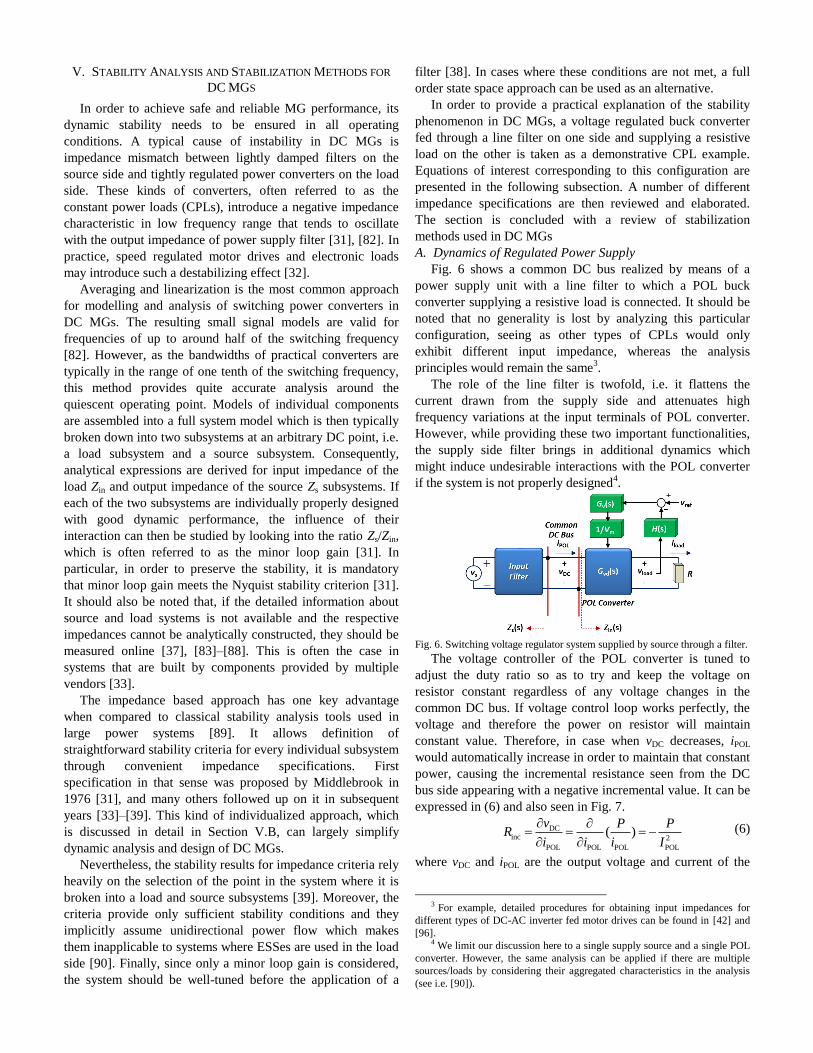
Fig. 6 shows a common DC bus realized by means of a
power supply unit with a line filter to which a POL buck
converter supplying a resistive load is connected. It should be
noted that no generality is lost by analyzing this particular
configuration, seeing as other types of CPLs would only
exhibit different input impedance, whereas the analysis
principles would remain the same3.
The role of the line filter is twofold, i.e. it flattens the
current drawn from the supply side and attenuates high
frequency variations at the input terminals of POL converter.
However, while providing these two important functionalities,
the supply side filter brings in additional dynamics which
might induce undesirable interactions with the POL converter
if the system is not properly designed4.
Fig. 6. Switching voltage regulator system supplied by source through a filter.
The voltage controller of the POL converter is tuned to
adjust the duty ratio so as to try and keep the voltage on
resistor constant regardless of any voltage changes in the
common DC bus. If voltage control loop works perfectly, the
voltage and therefore the power on resistor will maintain
constant value. Therefore, in case when vDC decreases, iPOL
would automatically increase in order to maintain that constant
power, causing the incremental resistance seen from the DC
bus side appearing with a negative incremental value. It can be
expressed in (6) and also seen in Fig. 7.
DCinc 2
POL POL POL POL
( )v P P
Ri i i I
(6)
where vDC and iPOL are the output voltage and current of the
3 For example, detailed procedures for obtaining input impedances for
different types of DC-AC inverter fed motor drives can be found in [42] and
[96]. 4 We limit our discussion here to a single supply source and a single POL
converter. However, the same analysis can be applied if there are multiple
sources/loads by considering their aggregated characteristics in the analysis
(see i.e. [90]).
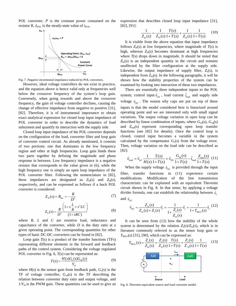
POL converter, P is the constant power consumed on the
resistor R, IPOL is the steady-state value of iPOL.
Operating Point: (VDC, IPOL)Rinc = -ΔvDC/ΔiPOL < 0
vDC
iPOL
vDCiPOL = P
ΔvDC
ΔiPOL
Constant Power Curve
Fig. 7. Negative incremental impedance induced by POL converters.
However, ideal voltage controllers do not exist in practice,
and the equation above is hence valid only at frequencies well
below the crossover frequency of the system’s loop gain.
Conversely, when going towards and above the crossover
frequency, the gain of voltage controller declines, causing the
change of effective impedance from negative to positive [31],
[82]. Therefore, it is of instrumental importance to obtain
exact analytical expression for closed loop input impedance of
POL converter in order to describe the dynamics of load
subsystem and quantify its interaction with the supply side.
Closed loop input impedance of the POL converter depends
on the configuration of the load, converter filter and loop gain
of converter control circuit. As already mentioned, it consists
of two portions: one that dominates in the low frequency
region and other at high frequencies. Loop gain binds these
two parts together by defining the magnitude and phase
response in between. Low frequency impedance is a negative
resistor that corresponds to the value given in (6), while the
high frequency one is simply an open loop impedance of the
POL converter filter. Following the nomenclature in [82],
these impedances are designated as ZN(s) and ZD(s),
respectively, and can be expressed as follows if a buck POL
converter is considered:
N inc 2( )
RZ s R
D (7)
2
D 2
1
( )1
Ls s LC
R RZ s
D sRC
(8)
where R, L and C are resistive load, inductance and
capacitance of the converter, while D is the duty ratio at a
given operating point. The corresponding quantities for other
types of basic DC-DC converters can be found in [82].
Loop gain T(s) is a product of the transfer functions (TFs)
representing different elements in the forward and feedback
paths of the control system. Considering the voltage regulated
POL converter in Fig. 6, T(s) can be represented as:
c vd
m
( ) ( ) ( )( )
H s G s G sT s
V (9)
where H(s) is the sensor gain from feedback path, Gc(s) is the
TF of voltage controller, Gvd(s) is the TF describing the
relation between converter duty ratio and output voltage, and
1/Vm is the PWM gain. These quantities can be used to give an
expression that describes closed loop input impedance [31],
[82], [91]:
in N D
1 1 ( ) 1 1
( ) ( ) 1 ( ) ( ) 1 ( )
T s
Z s Z s T s Z s T s
(10)
It is visible from the above equation that input impedance
follows ZN(s) at low frequencies, where magnitude of T(s) is
high, whereas ZD(s) becomes dominant at high frequencies
where T(s) drops down in magnitude. It should be noted that
Zin(s) is an independent quantity in the circuit and remains
unaffected by the filter configuration at the supply side.
Likewise, the output impedance of supply filter, Zs(s), is
independent from Zin(s). In the following paragraphs, it will be
shown how the stability properties of the system can be
examined by looking into interaction of these two impedances.
There are essentially three independent inputs to the POL
system; control inputrefv , load current
loadi and supply side
voltage DCv . The reason why caps are put on top of these
inputs is that the model considered here is linearized around
operating point and we are interested only with small signal
variations. The output voltage variation in open loop can be
described by linear combination of inputs, where Gvd(s), Gvg(s)
and Zout(s) represent corresponding open loop transfer
functions (see [82] for details). Once the control loop is
closed, control input becomes a variable in the system
calculated by the compensator Gc(s) from the voltage error.
Then, voltage variation on the load side can be described as
[82]:
vg outload ref DC load
( ) ( )1 ( ) ˆˆ ˆ ˆ( ) 1 ( ) 1 ( ) 1 ( )
G s Z sT sv v v i
H s T s T s T s
(11)
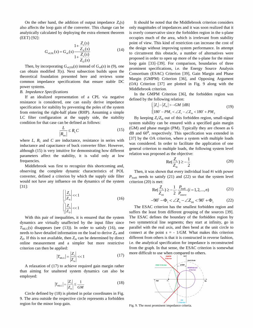
When the supply voltage DCv is provided through the input
filter, transfer functions in (11) experience certain
modifications. Modification of the line transmission
characteristic can be explained with an equivalent Thevenin
circuit shown in Fig. 8. In that sense, by applying a voltage
divider formula, one can establish the relationship between sv
and DCv
inDC s s s
sin s MLG
in
( ) 1 1ˆ ˆ ˆ ˆ
( )( ) ( ) 1 ( )1
( )
Z sv v v v
Z sZ s Z s T s
Z s
(12)
It can be seen from (12) how the stability of the whole
system is determined by the relation Zs(s)/Zin(s), which is in
literature commonly referred to as the minor loop gain or
TMLG(s) [31], [90], which can be expressed as:
s s sMLG
in N D
( ) ( ) ( )( ) 1( )
( ) ( ) 1 ( ) ( ) 1 ( )
Z s Z s Z sT sT s
Z s Z s T s Z s T s
(13)
Fig. 8. Thevenin equivalent source and load converter model.
On the other hand, the addition of output impedance Zs(s)
also affects the loop gain of the converter. This change can be
analytically calculated by deploying the extra element theorem
(EET) [92]:
s
Nvd,filt vd
s
D
( )1
( )( ) ( )
( )1
( )
Z s
Z sG s G s
Z s
Z s
(14)
Then, by incorporating Gvd,filt(s) instead of Gvd(s) in (9), one
can obtain modified T(s). Next subsection builds upon the
theoretical foundation presented here and reviews some
common impedance specifications that ensure stable DC
power systems.
B. Impedance Specifications
If an idealized representation of a CPL via negative
resistance is considered, one can easily derive impedance
specification for stability by preventing the poles of the system
from entering the right-half plane (RHP). Assuming a simple
LC filter configuration at the supply side, the stability
condition for that case can be defined as follows:
L
inc
LR C
R (15)
where L, RL and C are inductance, resistance in series with
inductance and capacitance of buck converter filter. However,
although (15) is very intuitive for demonstrating how different
parameters affect the stability, it is valid only at low
frequencies.
Middlebrook was first to recognize this shortcoming and,
observing the complete dynamic characteristics of POL
converter, defined a criterion by which the supply side filter
would not have any influence on the dynamics of the system
[31]:
s
N
s
D
1
1
Z
Z
Z
Z
(16)
With this pair of inequalities, it is ensured that the system
dynamics are virtually unaffected by the input filter since
TMLG(s) disappears (see (13)). In order to satisfy (16), one
needs to have detailed information on the load to derive ZN and
ZD. If this is not available, then Zin can be determined by direct
online measurement and a simpler but more restrictive
criterion can then be applied:
s
MLG
in
1Z
TZ
(17)
A relaxation of (17) to achieve required gain margin rather
than aiming for unaltered system dynamics can also be
employed:
s
MLG
in
1ZT
Z GM (18)
Circle defined by (18) is plotted in polar coordinates in Fig.
9. The area outside the respective circle represents a forbidden
region for the minor loop gain.
It should be noted that the Middlebrook criterion considers
only magnitudes of impedances and it was soon realized that it
is overly conservative since the forbidden region in the s-plane
occupies much of the area, which is irrelevant from stability
point of view. This kind of restriction can increase the cost of
the design without improving system performance. In attempt
to circumvent this obstacle, a number of alternatives were
proposed in order to open up more of the s-plane for the minor
loop gain [33]–[39]. For comparison, boundaries of three
prominent specifications, i.e. the Energy Source Analysis
Consortium (ESAC) Criterion [39], Gain Margin and Phase
Margin (GMPM) Criterion [36], and Opposing Argument
(OA) Criterion [37] are plotted in Fig. 9 along with the
Middlebrook criterion.
In the GMPM Criterion [36], the forbidden region was
defined by the following relation:
s in
1 s in 2
[dB]
180 180
Z Z GM
PM Z Z PM
(19)
By keeping Zs/Zin out of this forbidden region, small-signal
system stability can be ensured with a specified gain margin
(GM) and phase margin (PM). Typically they are chosen as 6
dB and 60⁰, respectively. This specification was extended in
[37] by the OA criterion, where a system with multiple loads
was considered. In order to facilitate the application of one
general criterion to multiple loads, the following system level
relation was proposed as the objective:
s
in
1Re( )
2
Z
Z (20)
Then, it was shown that every individual load #i with power
Ploadi needs to satisfy (21) and (22) so that the system level
criterion (20) is met:
s loadi
ini source
1Re( ) ( 1,2,..., )
2
Z Pi n
Z P (21)
i s ini i90 90Z Z (22)
The ESAC criterion has the smallest forbidden region and
suffers the least from different grouping of the sources [39].
The ESAC defines the boundary of the forbidden region by
two symmetrical line segments; they start at infinity, go in
parallel with the real axis, and then bend at the unit circle to
connect at the point s = - 1/GM. What makes this criterion
different from others is that it is constructed in reverse fashion,
i.e. the analytical specification for impedance is reconstructed
from the graph. In that sense, the ESAC criterion is somewhat
more difficult to use when compared to others.
Unit Circle
Middlebrook Criterion
OA Criterion
GMPM Criterion
ESAC Criterion
-1
1/GM
PM Re
Im
Fig. 9. The most prominent impedance criteria.
C. Stabilization Strategies
The common way of meeting impedance criteria is to
smooth the resonant peak of the input filter by adding physical
resistors in series and/or parallel with respective inductors and
capacitors [31], [40], [82], [93]. This approach is commonly
referred to as passive stabilization and an extensive overview
of these kinds of techniques for DC systems can be found in
[82]. However, adding physical damping elements introduces
dissipative losses to the system. Therefore, researchers have
come up with active damping solutions where stabilization can
be achieved only by modifying the POL converter or source
converter control loops. A review of several prominent active
damping methods is provided next.
Active damping can be divided into small- and large-signal
strategies. The basic principle in small-signal stabilization
strategies is the introduction of linear feedback control loop
that modifies the loop gain of the system T(s) and produces
similar damping effects as the real damping elements, but
without sacrificing the efficiency [20], [94], [95]. From the
minor loop gain specification viewpoint, active damping is
able to shape either the closed loop impedance of the POL
converter Zin(s) or output impedance of power supply Zs. One
example of shaping Zin is shown in [42] where the proposed
stabilization block is a proportional compensator followed by
a band-pass filter. This block takes DC link voltage as input
and adds its output to speed-control calculated current
reference in q-axis. The influence of this control loop, which is
shown in Fig. 10, on Zin(s) for the PMSM drive is studied in
detail, while proportional gain of the stabilizer is selected by
inspecting Nyquist diagrams. Similar approach is adopted for
brushless DC (BLDC) motor-drive in [96], but the root locus
method is used to shape Zin(s).
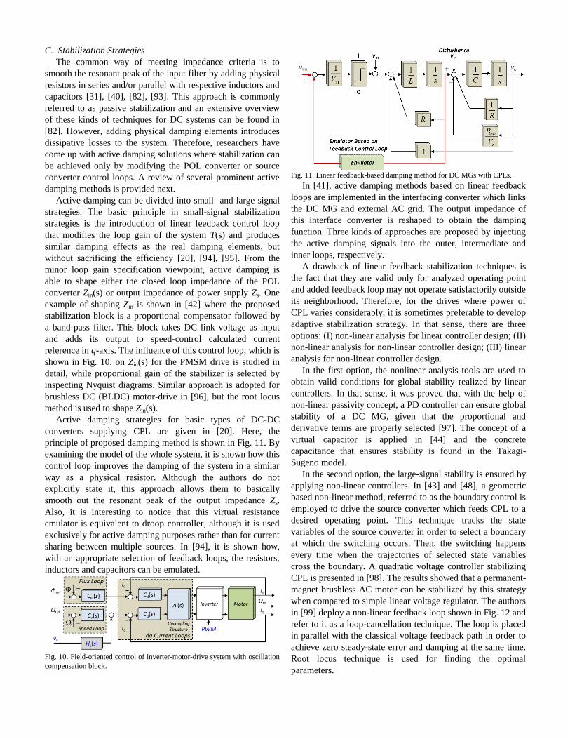
Active damping strategies for basic types of DC-DC
converters supplying CPL are given in [20]. Here, the
principle of proposed damping method is shown in Fig. 11. By
examining the model of the whole system, it is shown how this
control loop improves the damping of the system in a similar
way as a physical resistor. Although the authors do not
explicitly state it, this approach allows them to basically
smooth out the resonant peak of the output impedance Zs.
Also, it is interesting to notice that this virtual resistance
emulator is equivalent to droop controller, although it is used
exclusively for active damping purposes rather than for current
sharing between multiple sources. In [94], it is shown how,
with an appropriate selection of feedback loops, the resistors,
inductors and capacitors can be emulated.
Fig. 10. Field-oriented control of inverter-motor-drive system with oscillation
compensation block.
Fig. 11. Linear feedback-based damping method for DC MGs with CPLs.
In [41], active damping methods based on linear feedback
loops are implemented in the interfacing converter which links
the DC MG and external AC grid. The output impedance of
this interface converter is reshaped to obtain the damping
function. Three kinds of approaches are proposed by injecting
the active damping signals into the outer, intermediate and
inner loops, respectively.
A drawback of linear feedback stabilization techniques is
the fact that they are valid only for analyzed operating point
and added feedback loop may not operate satisfactorily outside
its neighborhood. Therefore, for the drives where power of
CPL varies considerably, it is sometimes preferable to develop
adaptive stabilization strategy. In that sense, there are three
options: (I) non-linear analysis for linear controller design; (II)
non-linear analysis for non-linear controller design; (III) linear
analysis for non-linear controller design.
In the first option, the nonlinear analysis tools are used to
obtain valid conditions for global stability realized by linear
controllers. In that sense, it was proved that with the help of
non-linear passivity concept, a PD controller can ensure global
stability of a DC MG, given that the proportional and
derivative terms are properly selected [97]. The concept of a
virtual capacitor is applied in [44] and the concrete
capacitance that ensures stability is found in the Takagi-
Sugeno model.
In the second option, the large-signal stability is ensured by
applying non-linear controllers. In [43] and [48], a geometric
based non-linear method, referred to as the boundary control is
employed to drive the source converter which feeds CPL to a
desired operating point. This technique tracks the state
variables of the source converter in order to select a boundary
at which the switching occurs. Then, the switching happens
every time when the trajectories of selected state variables
cross the boundary. A quadratic voltage controller stabilizing
CPL is presented in [98]. The results showed that a permanent-
magnet brushless AC motor can be stabilized by this strategy
when compared to simple linear voltage regulator. The authors
in [99] deploy a non-linear feedback loop shown in Fig. 12 and
refer to it as a loop-cancellation technique. The loop is placed
in parallel with the classical voltage feedback path in order to
achieve zero steady-state error and damping at the same time.
Root locus technique is used for finding the optimal
parameters.
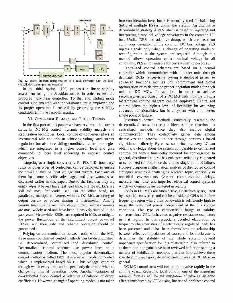
Fig. 12. Block diagram representation of a buck converter with the loop-
cancellation technique implemented.
In the third option, [100] proposes a linear stability
assessment using the Jacobian matrix in order to test the
proposed non-linear controller. To that end, sliding mode
control supplemented with the washout filter is employed and
its proper operation is ensured by generating the stability
conditions from the Jacobian matrix.
VI. CONCLUDING REMARKS AND FUTURE TRENDS
In the first part of this paper, we have reviewed the current
status in DC MG control, dynamic stability analysis and
stabilization techniques. Local control of converters plays an
instrumental role not only in achieving voltage and current
regulation, but also in enabling coordinated control strategies
which are integrated in a higher control level and give
commands to local level according to imposed control
objectives.
Targeting at a single converter, a PI, PD, PID, boundary,
fuzzy or other types of controllers can be deployed to ensure
the power quality of local voltage and current. Each one of
them has some specific advantages and disadvantages as
discussed earlier in this paper. Due to the fact that they are
easily adjustable and have fast lead time, PID based LCs are
still the most frequently used. On the other hand, for
paralleling multiple converters within a DC MG, accuracy of
output current or power sharing is instrumental. Among
various load sharing methods, droop control and its variants
are most widely used and have been intensively studied in the
past years. Meanwhile, ESSes are required in MGs to mitigate
the power fluctuation of the intermittent output power of
RESes, and their safe and reliable operation should be
guaranteed.
Relying on communication between units within the MG,
three main coordinated control methods can be distinguished,
i.e. decentralized, centralized and distributed control.
Decentralized control schemes use power lines as a
communication medium. The most popular decentralized
control method is called DBS. It is a variant of droop control
which is implemented based on DC bus voltage variation
through which every unit can independently determine when to
change its internal operation mode. Another variation of
conventional droop control is adaptive calculation of droop
coefficients. However, change of operating modes is not taken
into consideration here, but it is normally used for balancing
SoCs of multiple ESSes within the system. An alternative
decentralized strategy is PLS which is based on injecting and
interpreting sinusoidal voltage waveforms in the common DC
bus. Unlike DBS and adaptive droop, which are based on
continuous deviation of the common DC bus voltage, PLS
injects signals only when a change of operating mode or
reconfiguration in the system are required. Although this
method allows operation under nominal voltage in all
conditions, PLS is not suitable for current sharing purposes.
Centralized control schemes are based on a central
controller which communicates with all other units through
dedicated DCLs. Supervisory system is deployed to realize
advanced functions such as unit commitment and global
optimization or to determine proper operation modes for each
unit in DC MGs, In addition, in order to achieve
secondary/tertiary control of a DC MG with multiple units, a
hierarchical control diagram can be employed. Centralized
control offers the highest level of flexibility for achieving
advanced functionalities, but is a system with an inherent
single point of failure.
Distributed control methods structurally resemble the
decentralized ones, but can achieve similar functions as
centralized methods since they also involve digital
communication. They collectively gather data among
themselves and process it either through consensus based
algorithms or directly. By consensus principle, every LC can
obtain knowledge about the system comparable to centralized
control, but with a time delay required for convergence. In
general, distributed control has enhanced reliability compared
to centralized control, since there is no single point of failure.
However, rigorous mathematical analysis of distributed control
strategies remains a challenging research topic, especially in
non-ideal environments (variant communication delays,
measurement noise, and imperfect electrical control systems)
which we commonly encountered in real life.
Loads in DC MGs are often active, electronically regulated
by a specific converter, and can be considered CPLs in the low
frequency region where their bandwidth is sufficiently high to
make the consumed power independent of the bus voltage
variations. This type of characteristic brings in stability
concerns since CPLs behave as negative resistance oscillators
in that region. In this respect, a detailed elaboration of
frequency characteristics of electronically regulated loads has
been presented and it has been shown how the relationship
between effective impedances of source and load subsystems
determines the stability of the whole system. Several
impedance specification for this relationship, also referred to
as the minor loop gain, have been reviewed before presenting a
number of stabilization methods that can help achieve these
specifications and good dynamic performance of DC MGs in
general.
DC MG control area will continue to evolve rapidly in the
coming years. Regarding local control, one of the important
research focuses will be the mitigation of adverse dynamic
effects introduced by CPLs using linear and nonlinear control
techniques. On the coordinated control level, design of
centralized controllers for optimal demand response in
variable grid price scenario presents a significant future
challenge. New versions of DBS, PLS and adaptive droop
decentralized control methods will attempt to increase their
intelligence level. With regard to that, extended functionalities
such as differentiation of loads according to their supply
priority or sources in line with their specific characteristics
will be implemented. Distributed control strategies which have
recently spurred a great amount of interest in the DC MG
research community, will also continue its development. In
particular, as opposed to advocated advantages in terms of
increased redundancy and reliability in relation to centralized
control, a better understanding of their implications on the
stability of the overall system will need to be obtained.
Development of impedance based models of a wide class of
variable speed motor drives is yet another prominent research
topic. Due to their complex control architecture, it is highly
desirable to develop simplified models which can represent the
dynamics of the drive with acceptable accuracy. These
impedance models can then be used either for simulation of
larger scale DC MGs (with reduced computational burden) or
for fast stability verification using some of the impedance
criteria that were reviewed in this paper.
REFERENCES
[1] A. Ipakchi and F. Albuyeh, “Grid of the Future,” IEEE Power Energy
Mag., vol. 7, no. 2, pp. 52–62, 2009.
[2] R. H. Lasseter, “MicroGrids,” in IEEE Power Engineering Society
Winter Meeting, 2002, pp. 305–308.
[3] J. M. Guerrero, J. C. Vasquez, J. Matas, L. G. de Vicuna, and M.
Castilla, “Hierarchical Control of Droop-Controlled AC and DC
Microgrids—A General Approach Toward Standardization,” IEEE Trans. Ind.
Electron., vol. 58, no. 1, pp. 158–172, 2011.
[4] N. Pogaku, M. Prodanovic, and T. C. Green, “Modeling, Analysis and
Testing of Autonomous Operation of an Inverter-Based Microgrid,” IEEE
Trans. Power Electron., vol. 22, no. 2, pp. 613–625, 2007.
[5] J. M. Guerrero, M. Castilla, J. C. Vasquez, J. Matas, and L. G. de
Vicuna, “Control Strategy for Flexible Microgrid Based on Parallel Line-
Interactive UPS Systems,” IEEE Trans. Ind. Electron., vol. 56, no. 3, pp.
726–736, 2009.
[6] R. Majumder, B. Chaudhuri, A. Ghosh, G. Ledwich, and F. Zare,
“Improvement of Stability and Load Sharing in an Autonomous Microgrid
Using Supplementary Droop Control Loop,” IEEE Trans. Power Syst., vol.
25, no. 2, pp. 796–808, 2010.
[7] K. De Brabandere, B. Bolsens, J. den Keybus, A. Woyte, J. Driesen,
and R. Belmans, “A Voltage and Frequency Droop Control Method for
Parallel Inverters,” IEEE Trans. Power Electron., vol. 22, no. 4, pp. 1107–
1115, 2007.
[8] J. A. Peas Lopes, C. L. Moreira, and A. G. Madureira, “Defining
Control Strategies for MicroGrids Islanded Operation,” IEEE Trans. Power
Syst., vol. 21, no. 2, pp. 916–924, 2006.
[9] J. Rocabert, A. Luna, F. Blaab erg, and P. Rodr guez, “Control of
Power Converters in AC Microgrids,” IEEE Trans. Power Electron., vol. 27,
no. 11, pp. 4734–4749, 2012.
[10] Y. W. Li and C.-N. Kao, “An Accurate Power Control Strategy for
Power-Electron.-Interfaced Distributed Generation Units Operating in a Low-
Voltage Multibus Microgrid,” IEEE Trans. Power Electron., vol. 24, no. 12,
pp. 2977–2988, 2009.
[11] Q.-C. Zhong, “Robust Droop Controller for Accurate Proportional Load
Sharing Among Inverters Operated in Parallel,” IEEE Trans. Ind. Electron.,
vol. 60, no. 4, pp. 1281–1290, 2013.
[12] T. Dragicevic, J. C. Vasquez, J. M. Guerrero, and D. Skrlec, “Advanced
LVDC Electrical Power Architectures and Microgrids: A Step Toward a New
Generation of Power Distribution Networks,” IEEE Electrif. Mag., vol. 2, no.
1, pp. 54–65, 2014.
[13] D. Salomonsson, L. Soder, and A. Sannino, “An Adaptive Control
System for a DC Microgrid for Data Centers,” IEEE Trans. Ind. Appl., vol. 44,
no. 6, pp. 1910–1917, 2008.
[14] H. Kakigano, Y. Miura, and T. Ise, “Distribution Voltage Control for
DC Microgrids Using Fuzzy Control and Gain-Scheduling Technique,” IEEE
Trans. Power Electron., vol. 28, no. 5, pp. 2246–2258, 2013.
[15] K. Sun, L. Zhang, Y. Xing, and J. M. Guerrero, “A Distributed Control
Strategy Based on DC Bus Signaling for Modular Photovoltaic Generation
Systems With Battery Energy Storage,” IEEE Trans. Power Electron., vol. 26,
no. 10, pp. 3032–3045, 2011.
[16] J. Schonberger, R. Duke, and S. D. Round, “DC-Bus Signaling: A
Distributed Control Strategy for a Hybrid Renewable Nanogrid,” IEEE Trans.
Ind. Electron., vol. 53, no. 5, pp. 1453–1460, 2006.
[17] P. Karlsson and J. Svensson, “DC Bus Voltage Control for a
Distributed Power System,” IEEE Trans. Power Electron., vol. 18, no. 6, pp.
1405–1412, 2003.
[18] R. S. Balog and P. T. Krein, “Bus Selection in Multibus DC
Microgrids,” IEEE Trans. Power Electron., vol. 26, no. 3, pp. 860–867, 2011.
[19] R. S. Balog, Autonomous Local Control in Distributed DC Power
Systems. PhD Thesis, 2006.
[20] A. M. Rahimi and A. Emadi, “Active Damping in DC/DC Power
Electronic Converters: A Novel Method to Overcome the Problems of
Constant Power Loads,” IEEE Trans. Ind. Electron., vol. 56, no. 5, pp. 1428–
1439, May 2009.
[21] B. K. Johnson, R. H. Lasseter, F. L. Alvarado, and R. Adapa,
“Expandable Multiterminal DC System Based on Voltage Droop,” IEEE
Trans. Power Deliv., vol. 8, no. 4, pp. 1926–1932, 1993.
[22] V. Nasirian, S. Moayedi, A. Davoudi, and F. Lewis, “Distributed
Cooperative Control of DC Microgrids,” IEEE Trans. Power Electron., vol.
30, no. 4, pp. 2288–2303, 2015.
[23] S. Anand, B. G. Fernandes, and J. M. Guerrero, “Distributed Control to
Ensure Proportional Load Sharing and Improve Voltage Regulation in Low-
Voltage DC Microgrids,” IEEE Trans. Power Electron., vol. 28, no. 4, pp.
1900–1913, 2013.
[24] Q. Shafiee, T. Dragicevic, F. Andrade, J. C. Vasquez, and J. M.
Guerrero, “Distributed Consensus-Based Control of Multiple DC-Microgrids
Clusters,” in Annual Conference of the IEEE Industrial Electronics Society,
2014, pp. 2056–2062.
[25] L. Meng, T. Dragicevic, J. M. Guerrero, and J. C. Vasquez, “Dynamic
Consensus Algorithm Based Distributed Global Efficiency Optimization of a
Droop Controlled DC Microgrid,” in IEEE International Energy Conference,
2014.
[26] E. Koutroulis and K. Kalaitzakis, “Design of a Maximum Power
Tracking System for Wind-Energy-Conversion Applications,” IEEE Trans.
Ind. Electron., vol. 53, no. 2, pp. 486–494, Apr. 2006.
[27] B. Subudhi and R. Pradhan, “A Comparative Study on Maximum
Power Point Tracking Techniques for Photovoltaic Power Systems,” IEEE
Trans. Sustain. Energy, vol. 4, no. 1, pp. 89–98, Jan. 2013.
[28] T. Dragicevic, J. M. Guerrero, J. C. Vasquez, and D. Skrlec,
“Supervisory Control of an Adaptive-Droop Regulated DC Microgrid With
Battery Management Capability,” IEEE Trans. Power Electron., vol. 29, no.
2, pp. 695–706, 2014.
[29] X. Lu, K. Sun, J. M. Guerrero, J. C. Vasquez, and L. Huang, “Double-
Quadrant State-of-Charge-Based Droop Control Method for Distributed
Energy Storage Systems in Autonomous DC Microgrids,” IEEE Trans. Smart
Grid, vol. 6, no. 1, pp. 147–157, Jan. 2015.
[30] X. Lu, K. Sun, J. M. Guerrero, J. C. Vasquez, and L. Huang, “State-of-
Charge Balance Using Adaptive Droop Control for Distributed Energy
Storage Syst. in DC Microgrid Appl.,” IEEE Trans. Ind. Electron., vol. 61, no.
6, pp. 2804–2815, 2014.
[31] R. D. Middlebrook, “Input Filter Considerations in Design and
Application of Switching Regulators,” in IEEE Ind. Applicat. Soc. Annu.
Meeting, 1976, pp. 366–382.
[32] A. Emadi, A. Khaligh, C. H. Rivetta, and G. A. Williamson, “Constant
Power Loads and Negative Impedance Instability in Automotive Systems:
Definition, Modeling, Stability, and Control of Power Electronic Converters
and Motor Drives,” IEEE Trans. Veh. Technol., vol. 55, no. 4, pp. 1112–1125,
2006.
[33] S. D. Sudhoff and J. M. Crider, “Advancements in Generalized
Immittance based Stability Analysis of DC Power Electronics based
Distribution Systems,” in IEEE Electric Ship Technologies Symposium, 2011,
pp. 207–212.
[34] A. Riccobono and E. Santi, “A Novel Passivity-Based Stability
Criterion (PBSC) for Switching Converter DC Distribution Systems,” in 27th
Annual IEEE Applied Power Electronics Conference and Exposition (APEC),
2012, pp. 2560–2567.
[35] M. Belkhayat, R. Cooley, and A. Witulski, “Large Signal Stability
Criteria for Distributed Systems with Constant Power Loads,” in Annual
IEEE Power Electron. Specialists Conference, 1995, vol. 2, pp. 1333–1338.
[36] C. M. Wildrick, F. C. Lee, B. H. Cho, and B. Choi, “A Method of
Defining the Load Impedance Specification for a Stable Distributed Power
System,” IEEE Trans. Power Electron., vol. 10, no. 3, pp. 280–285, 1995.
[37] X. Feng, J. Liu, and F. C. Lee, “Impedance Specifications for Stable
DC Distributed Power Systems,” IEEE Trans. Power Electron., vol. 17, no. 2,
pp. 157–162, 2002.
[38] X. Wang, R. Yao, and F. Rao, “Three-Step Impedance Criterion for
Small-Signal Stability Analysis in Two-Stage DC Distributed Power
Systems,” IEEE Power Electron. Lett., vol. 1, no. 3, pp. 83–87, 2003.
[39] S. D. Sudhoff, S. F. Glover, P. T. Lamm, D. H. Schmucker, and D. E.
Delisle, “Admittance Space Stability Analysis of Power Electronic Systems,”
IEEE Trans. Aerosp. Electron. Syst., vol. 36, no. 3, pp. 965–973, 2000.
[40] M. Cespedes, L. Xing, and J. Sun, “Constant-Power Load System
Stabilization by Passive Damping,” IEEE Trans. Power Electron., vol. 26, no.
7, pp. 1832–1836, 2011.
[41] A. A. A. Radwan and Y. A.-R. I. Mohamed, “Linear Active
Stabilization of Converter-Dominated DC Microgrids,” IEEE Trans. Smart
Grid, vol. 3, no. 1, pp. 203–216, 2012.
[42] P. Liutanakul, A.-B. Awan, S. Pierfederici, B. Nahid-Mobarakeh, and F.
Meibody-Tabar, “Linear Stabilization of a DC Bus Supplying a Constant
Power Load: A General Design Approach,” IEEE Trans. Power Electron., vol.
25, no. 2, pp. 475–488, 2010.
[43] A. Kwasinski and C. N. Onwuchekwa, “Dynamic Behavior and
Stabilization of DC Microgrids With Instantaneous Constant-Power Loads,”
IEEE Trans. Power Electron., vol. 26, no. 3, pp. 822–834, 2011.
[44] P. Magne, B. Nahid-Mobarakeh, and S. Pierfederici, “General Active
Global Stabilization of Multiloads DC-Power Networks,” IEEE Trans. Power
Electron., vol. 27, no. 4, pp. 1788–1798, 2012.
[45] D. Linden and T. B. Reddy, Handbook of Batteries. McGraw-Hill,
2002.
[46] L. Guo, J. Y. Hung, and R. M. Nelms, “Evaluation of DSP-Based PID
and Fuzzy Controllers for DC-DC Converters,” IEEE Trans. Ind. Electron.,
vol. 56, no. 6, pp. 2237–2248, Jun. 2009.
[47] N. L. Diaz, T. Dragicevic, J. C. Vasquez, and J. M. Guerrero,
“Intelligent Distributed Generation and Storage Units for DC Microgrids - A
New Concept on Cooperative Control Without Communications Beyond
Droop Control,” IEEE Trans. Smart Grid, vol. 5, no. 5, pp. 2476–2485, 2014.
[48] C. N. Onwuchekwa and A. Kwasinski, “Analysis of Boundary Control
for Buck Converters With Instantaneous Constant-Power Loads,” IEEE Trans.
Power Electron., vol. 25, no. 8, pp. 2018–2032, 2010.
[49] William S. Levine, The Control Handbook. CRC Press, 2010.
[50] M. Lee, D. Chen, K. Huang, C.-W. Liu, and B. Tai, “Modeling and
Design for a Novel Adaptive Voltage Positioning (AVP) Scheme for
Multiphase VRMs,” IEEE Trans. Power Electron., vol. 23, no. 4, pp. 1733–
1742, 2008.
[51] C.-J. Chen, D. Chen, C.-S. Huang, M. Lee, and E. K.-L. Tseng,
“Modeling and Design Considerations of a Novel High-Gain Peak Current
Control Scheme to Achieve Adaptive Voltage Positioning (AVP) for DC
Power Converters,” IEEE Trans. Power Electron., vol. 24, no. 12, pp. 2942–
2950, 2009.
[52] H.-H. Huang, C.-Y. Hsieh, J.-Y. Liao, and K.-H. Chen, “Adaptive
Droop Resistance Technique for Adaptive Voltage Positioning in Boost DC -
DC Converters,” IEEE Trans. Power Electron., vol. 26, no. 7, pp. 1920–1932,
2011.
[53] X. Lu, J. M. Guerrero, K. Sun, and J. C. Vasquez, “An Improved Droop
Control Method for DC Microgrids Based on Low Bandwidth
Communication With DC Bus Voltage Restoration and Enhanced Current
Sharing Accuracy,” IEEE Trans. Power Electron., vol. 29, no. 4, pp. 1800–
1812, 2014.
[54] Y. Gu, X. Xiang, W. Li, and X. He, “Mode-Adaptive Decentralized
Control for Renewable DC Microgrid With Enhanced Reliability and
Flexibility,” IEEE Trans. Power Electron., vol. 29, no. 9, pp. 5072–5080,
2014.
[55] D. Boroyevich, I. Cvetkovic, D. Dong, R. Burgos, F. Wang, and F. Lee,
“Future Electronic Power Distribution Systems: A Contemplative View,” in
International Conference on Optimization of Electrical and Electronic
Equipment, 2010, pp. 1369–1380.
[56] K. Strunz, E. Abbasi, and D. N. Huu, “DC Microgrid for Wind and
Solar Power Integration,” IEEE J. Emerg. Sel. Top. Power Electron., vol. 2,
no. 1, pp. 115–126, Mar. 2014.
[57] C. Gavriluta, I. J., C. Citro, J. Rocabert, and P. Rodriguez,
“Decentralized Primary Control of MTDC Networks with Energy Storage and
Distributed Generation,” IEEE Trans. Ind. Appl., vol. 50, no. 6, pp. 4122–
4131, 2014.
[58] Y. Gu, W. Li, and X. He, “Frequency-Coordinating Virtual Impedance
for Autonomous Power Management of DC Microgrid,” IEEE Trans. Power
Electron., vol. 30, no. 4, pp. 2328–2337, 2015.
[59] T. Dragicevic, S. Sucic, J. C. Vasquez, and J. M. Guerrero, “Flywheel-
Based Distributed Bus Signalling Strategy for the Public Fast Charging
Station,” IEEE Trans. Smart Grid, vol. 5, no. 6, pp. 2825–2835, 2014.
[60] N. Hur, J. Jung, and K. Nam, “A Fast Dynamic DC-Link Power-
Balancing Scheme for a PWM Converter-Inverter System,” IEEE Trans. Ind.
Electron., vol. 48, no. 4, pp. 794–803, Aug. 2001.
[61] A. Gkountaras, S. Dieckerhoff, and T. Sezi, “Performance Analysis of
Hybrid Microgrids Applying SoC-Adaptive Droop Control,” in 16th
European Conference on Power Electronics and Applications, 2014, pp. 1–
10.
[62] E. Liegmann and R. Ma umder, “An Efficient Method of Multiple
Storage Control in Microgrids,” IEEE Trans. Power Syst.
[63] H. C. Ferreira, L. Lampe, J. Newbury, and T. G. Swart, Power Line
Communications: Theory and Appl. for Narrowband and Broadband
Communications over Power Lines. John Wiley & Sons, 2010.
[64] “REbus DC Microgrid.” [Online]. Available:
http://rebuspower.com/technical.shtml.
[65] T. Dragicevic, J. M. Guerrero, and J. C. Vasquez, “A Distributed
Control Strategy for Coordination of an Autonomous LVDC Microgrid Based
on Power-Line Signaling,” IEEE Trans. Ind. Electron., vol. 61, no. 7, pp.
3313–3326, 2014.
[66] W. Stefanutti, S. Saggini, P. Mattavelli, and M. Ghioni, “Power Line
Communication in Digitally Controlled DC-DC Converters Using Switching
Frequency Modulation,” IEEE Trans. Ind. Electron., vol. 55, no. 4, pp. 1509–
1518, 2008.
[67] F. Valenciaga and P. F. Puleston, “Supervisor Control for a Stand-
Alone Hybrid Generation System Using Wind and Photovoltaic Energy,”
IEEE Trans. Energy Convers., vol. 20, no. 2, pp. 398–405, 2005.
[68] F. Valenciaga and P. F. Puleston, “High-Order Sliding Control for a
Wind Energy Convers. System Based on a Permanent Magnet Synchronous
Generator,” IEEE Trans. Energy Convers., vol. 23, no. 3, pp. 860–867, 2008.
[69] G. Byeon, T. Yoon, S. Oh, and G. Jang, “Energy Management Strategy
of the DC Distribution System in Buildings Using the EV Service Model,”
IEEE Trans. Power Electron., vol. 28, no. 4, pp. 1544–1554, 2013.
[70] L. Che and M. Shahidehpour, “DC Microgrids: Economic Operation
and Enhancement of Resilience by Hierarchical Control,” IEEE Trans. Smart
Grid, vol. 5, no. 5, pp. 2517–2526, 2014.
[71] C. Jin, P. Wang, J. Xiao, Y. Tang, and F. H. Choo, “Implementation of
Hierarchical Control in DC Microgrids,” IEEE Trans. Ind. Electron., vol. 61,
no. 8, pp. 4032–4042, 2014.
[72] X. Lu, J. M. Guerrero, K. Sun, J. C. Vasquez, R. Teodorescu, and L.
Huang, “Hierarchical Control of Parallel AC-DC Converter Interfaces for
Hybrid Microgrids,” IEEE Trans. Smart Grid, vol. 5, no. 2, pp. 683–692,
2014.
[73] B. Wang, M. Sechilariu, and F. Locment, “Intelligent DC Microgrid
With Smart Grid Communications: Control Strategy Consideration and
Design,” IEEE Trans. Smart Grid, vol. 3, no. 4, pp. 2148–2156, 2012.
[74] Q. Shafiee, T. Dragicevic, J. C. Vasquez, and J. M. Guerrero,
“Hierarchical Control for Multiple DC-Microgrids Clusters,” IEEE Trans.
Energy Convers., vol. 29, no. 4, pp. 922–933, 2014.
[75] R. Olfati-Saber, J. A. Fax, and R. M. Murray, “Consensus and
Cooperation in Networked Multi-Agent Systems,” Proc. IEEE, vol. 95, no. 1,
pp. 215–233, 2007.
[76] R. Olfati-Saber and R. M. Murray, “Consensus Problems in Networks
of Agents with Switching Topology and Time-Delays,” IEEE Trans. Autom.
Control, vol. 49, no. 9, pp. 1520–1533, 2004.
[77] Z. Meng, W. Ren, Y. Cao, and Z. You, “Leaderless and Leader-
Following Consensus With Communication and Input Delays Under a
Directed Network Topology,” IEEE Trans. Syst. Man, Cybern. Part B
Cybern., vol. 41, no. 1, pp. 75–88, Feb. 2011.
[78] X. Lin and S. Boyd, “Fast Linear Iterations for Distributed Averaging,”
42nd IEEE Int. Conf. Decis. Control, vol. 5, 2003.
[79] F. L. Lewis, Z. Qu, A. Davoudi, and A. Bidram, “Secondary Control of
Microgrids based on Distributed Cooperative Control of Multi-Agent
Systems,” IET Gener. Transm. Distrib., vol. 7, no. 8, pp. 822–831, 2013.
[80] H. Behjati, A. Davoudi, and F. Lewis, “Modular DC - DC Converters
on Graphs: Cooperative Control,” IEEE Trans. Power Electron., vol. 29, no.
12, pp. 6725–6741, Dec. 2014.
[81] S. Abhinav, G. Binetti, A. Davoudi, and F. L. Lewis, “Toward
Consensus-Based Balancing of Smart Batteries,” in 29th Annual IEEE
Applied Power Electronics Conference and Exposition, 2014, pp. 2867–2873.
[82] R. W. Erickson and D. Maksimovic, Fundamentals of Power
Electronics. Springer, 2001.
[83] J. Liu, X. Feng, F. C. Lee, and D. Boro evich, “Stability Margin
Monitoring for DC Distributed Power Systems via Perturbation Approaches,”
IEEE Trans. Power Electron., vol. 18, no. 6, pp. 1254–1261, Nov. 2003.
[84] M. Shirazi, R. Zane, and D. Maksimovic, “An Autotuning Digital
Controller for DC-DC Power Converters Based on Online Frequency-
Response Measurement,” IEEE Trans. Power Electron., vol. 24, no. 11, pp.
2578–2588, Nov. 2009.
[85] J. A. Abu Qahouq and V. Arikatla, “Online Closed-Loop Autotuning
Digital Controller for Switching Power Converters,” IEEE Trans. Ind.
Electron., vol. 60, no. 5, pp. 1747–1758, 2013.
[86] J. Morroni, R. Zane, and D. Maksimovic, “Design and Implementation
of an Adaptive Tuning System Based on Desired Phase Margin for Digitally
Controlled DC-DC Converters,” IEEE Trans. Power Electron., vol. 24, no. 2,
pp. 559–564, Feb. 2009.
[87] A. Barkley and E. Santi, “Improved Online Identification of a D-DC
Converter and Its Control Loop Gain Using Cross-Correlation Methods,”
IEEE Trans. Power Electron., vol. 24, no. 8, pp. 2021–2031, Aug. 2009.
[88] J. Morroni, R. Zane, and D. Maksimovic, “An Online Stability Margin
Monitor for Digitally Controlled Switched-Mode Power Supplies,” IEEE
Trans. Power Electron., vol. 24, no. 11, pp. 2639–2648, Nov. 2009.
[89] P. Kundur, N. J. Balu, and M. G. Lauby, Power System Stability And
Control. New York: McGraw-Hill, 1994.
[90] A. Riccobono and E. Santi, “Comprehensive Review of Stability
Criteria for DC Power Distribution Systems,” IEEE Trans. Ind. Appl., vol. 50,
no. 5, pp. 3525–3535, 2014.
[91] M. K. Zamierczuk, R. C. Cravens, and A. Reatti, “Closed-Loop Input
Impedance of PWM Buck-Derived DC-DC Converters,” in IEEE
International Symposium on Circuits and Systems, 1994, vol. 6, pp. 61–64.
[92] R. D. Middlebrook, “Null Double In ection and the Extra Element
Theorem,” IEEE Trans. Edu., vol. 32, no. 3, pp. 167–180, Aug. 1989.
[93] A. M. Rahimi and A. Emadi, “An Analytical Investigation of DC/DC
Power Electronic Converters With Constant Power Loads in Vehicular Power
Systems,” IEEE Trans. Veh. Technol., vol. 58, no. 6, pp. 2689–2702, 2009.
[94] P. A. Dahono, “A Control Method for DC-DC Converter That Has an
LCL Output Filter based on New Virtual Capacitor and Resistor Concepts,”
in IEEE 35th Annual Power Electron. Specialists Conference, 2004, vol. 1,
pp. 36–42.
[95] X. Lu, K. Sun, J. M. Guerrero, J. C. Vasquez, L. Huang, and J. Wang,
“Stability Enhancement Based on Virtual Impedance for DC Microgrids With
Constant Power Loads,” IEEE Trans. Smart Grid, to appear.
[96] X. Liu, A. J. Forsyth, and A. M. Cross, “Negative Input-Resistance
Compensator for a Constant Power Load, ” IEEE Trans. Ind. Electron., vol.
54, no. 6, pp. 3188–3196, 2007.
[97] A. Kwasinski and P. T. Krein, “Passivity-Based Control of Buck
Converters with Constant-Power Loads,” in IEEE Power Electron. Specialists
Conference, 2007, pp. 259–265.
[98] J. Wang and D. Howe, “A Power Shaping Stabilizing Control Strategy
for DC Power Syst. With Constant Power Loads,” IEEE Trans. Power
Electron., vol. 23, no. 6, pp. 2982–2989, 2008.
[99] A. M. Rahimi, G. A. Williamson, and A. Emadi, “Loop-Cancellation
Technique: A Novel Nonlinear Feedback to Overcome the Destabilizing
Effect of Constant-Power Loads,” IEEE Trans. Veh. Technol., vol. 59, no. 2,
pp. 650–661, 2010.
[100] A. P. N. Tahim, D. J. Pagano, M. L. Heldwein, and E. Ponce, “Control
of Interconnected Power Electronic Converters in DC Distribution Systems,”
in Brazilian Power Electron. Conference, 2011, pp. 269–274.
Tomislav Dragičević (S’09-M’13) received the
M.E.E. and the industrial Ph.D. degree from the
Faculty of Electrical Engineering, Zagreb, Croatia,
in 2009 and 2013, respectively. His PhD thesis has
been carried out in close cooperation with industry
and he has received highest honours for it.
He is currently a Postdoctoral research associate at
the Institute of Energy Technology, Aalborg
University. His principal field of interest is overall
system design of autonomous and grid connected
DC and AC microgrids, and industrial application of advanced modelling,
control and protection concepts to shipboard power systems, remote telecom
stations, domestic and commercial facilities and electric vehicle charging
stations. He has authored and co-authored more than 60 technical papers in
his domain of interest. 18 of them are published in international journals.
Dr. Dragičević is a Member of the IEEE Power Electronics and IEEE Power
Systems Societies. He has served in Scientific Committee Boards in several
IEEE conferences and has been invited for guest lectures and tutorials in a
number of universities and companies around the world.
Xiaonan Lu (S’11-M’14) was born in Tianjin,
China, 1985. He received the B.E. and Ph.D.
degrees in electrical engineering from Tsinghua
University, Beijing, China, in 2008 and 2013,
respectively. From Sep. 2010 to Aug. 2011, he was
a guest Ph.D. student at Department of Energy
Technology, Aalborg University, Denmark. From
Oct. 2013 to Dec. 2014, he was a postdoc
researcher in the Department of Electrical
Engineering and Computer Science, University of
Tennessee, Knoxville. In Jan. 2015, he joined the Energy Systems Division,
Argonne National Laboratory, where he is currently a postdoc appointee.
His research interests are modeling and control of power electronic converters
in renewable energy systems and microgrids, hardware-in-the-loop real-time
test, multilevel converters, matrix converters, etc. Dr. Lu received the
Outstanding Reviewer Award for IEEE Transaction on Power Electronics in
2014. Dr. Lu is a member of IEEE PELS, IAS and PES Society.
Juan C. Vasquez (M’12-SM’14) received the B.S.
degree in electronics engineering from the
Autonomous University of Manizales, Manizales,
Colombia, and the Ph.D. degree in automatic
control, robotics, and computer vision from the
Technical University of Catalonia, Barcelona,
Spain, in 2004 and 2009, respectively. In 2011, he
was Assistant Professor in microgrids and
currently he is working as an Associate Professor
at the Department of Energy Technology, Aalborg
University, Denmark. Dr. Vasquez is the co-
responsible of the Research Program in Microgrids.
From Feb. 2015 to April. 2015 he was a Visiting Scholar at the Center of
Power Electronics Systems (CPES) at Virginia Tech.
His current research interests include operation, power management,
hierarchical control, optimization and power quality applied to distributed
generation and ac/dc microgrids. Dr. Vasquez is currently a member of the
IEC System Evaluation Group SEG4 on LVDC Distribution and Safety for
use in Developed and Developing Economies and the Renewable Energy
Systems Technical Committee TC-RES in IEEE Industrial Electronics Society.

Josep M. Guerrero (S’01-M’04-SM’08-FM’15)
received the B.S. degree in telecommunications
engineering, the M.S. degree in electronics
engineering, and the Ph.D. degree in power
electronics from the Technical University of
Catalonia, Barcelona, in 1997, 2000 and 2003,
respectively. Since 2011, he has been a Full
Professor with the Department of Energy
Technology, Aalborg University, Denmark,
where he is responsible for the Microgrid
Research Program. From 2012 he is a guest
Professor at the Chinese Academy of Science and the Nanjing University of
Aeronautics and Astronautics; from 2014 he is chair Professor in Shandong
University; and from 2015 he is a distinguished guest Professor in Hunan
University.
His research interests is oriented to different microgrid aspects, including
power electronics, distributed energy-storage systems, hierarchical and
cooperative control, energy management systems, and optimization of
microgrids and islanded minigrids. Prof. Guerrero is an Associate Editor for
the IEEE Transactions on Power Electronics, the IEEE Transactions on
Industrial Electronics, and the IEEE Industrial Electronics Magazine, and an
Editor for the IEEE Transactions on Smart Grid and IEEE Transactions on
Energy Conversion. He was the chair of the Renewable Energy Systems
Technical Committee of the IEEE Industrial Electronics Society. In 2014 he
was awarded by Thomson Reuters as Highly Cited Researcher, and in 2015
he was elevated as IEEE Fellow for his contributions on “distributed power
systems and microgrids.”