Embed Size (px)
Citation preview

Adam Equipment Company Ltd 2012
Adam Equipment
ABK AFK Service Manual
Part No- 3116611515 - Rev A - April 2012
Adam Equipment Company Ltd 2012
CONTENTS
1.0 PRODUCT DESCRIPTION...................................................................1 2.0 ABK SPECIFICATION TABLE ..............................................................2 3.0 AFK SPECIFICATION TABLE ..............................................................3 4.0 KEY DESCRIPTIONS ...........................................................................4 5.0 DISPLAYS.............................................................................................5 6.0 OPERATION.........................................................................................5
6.1 ZEROING THE DISPLAY..................................................................5 6.2 TARING.............................................................................................6 6.3 WEIGHING A SAMPLE .....................................................................6 6.4 PARTS COUNTING...........................................................................7 6.5 CHECK-WEIGHING ..........................................................................8 6.6 ACCUMULATED TOTAL...................................................................9 6.7 PERCENT WEIGHING....................................................................10 6.8 ANIMAL (Dynamic) WEIGHING ......................................................11
6.8.1 ANIMAL WEIGHING PROCEDURE .........................................12 7.0 USER PARAMETERS.........................................................................12
7.1 CHECK WEIGHING PARAMETERS...............................................13 7.2 PERCENT WEIGHING and ANIMAL WEIGHING ...........................14 7.3 RS-232 PARAMETERS...................................................................15 7.4 SCALE PARAMETERS ...................................................................16
8.0 BATTERY OPERATION......................................................................17 9.0 RELAY CONNECTIONS.....................................................................17 10.0 RS-232 INTERFACE...........................................................................18
10.1 INPUT COMMANDS FORMAT....................................................21 11.0 CALIBRATION ....................................................................................22 12.0 SERVICE SECTION............................................................................23
12.1 USING “0000” TO ENTER CALIBRATION MODE.......................23 12.2 USING “1000” TO ENTER THE SERVICE PARAMETERS.........23
12.2.1 F4 –INITIAL ZERO RANGE ..................................................24 12.2.2 F5 -RE-ZERO RANGE..........................................................24 12.2.3 F6 -SUCCESSIVE TARE ......................................................24 12.2.4 F7 –ADC COUNTS ...............................................................24 12.2.5 F8 –ZERO MODE .................................................................25 12.2.6 F9 –LOW VOLTAGE DETECTION .......................................25 12.2.7 FA –AZn AUTO ZERO RANGE ............................................25 12.2.8 Fb –FPS USER FUNCTION PASSWORD ...........................25
13.0 ERROR MESSAGES AND TROUBLESHOOTING.............................26 14.0 LOAD CELL CHECK...........................................................................28 15.0 LOAD CELL REMOVAL AND REPLACEMENT..................................28 16.0 LOAD CELL CABLE TO INDICATOR CONNECTIONS......................30 17.0 PARTS LIST........................................................................................31 18.0 WARRANTY INFORMATION..............................................................32

1 Adam Equipment Company Ltd 2012
The ABK/AFK series of products are bench and floor type platform scales. They are available in 3 x base sizes and a number of different model capacities. The base is constructed using 2 x crosses or frames connected by a single point load cell which outputs weight to the Indicator via a cable. The top pan and pillar are 304 stainless steel and all models offer a fully adjustable Indicator bracket. The Indicator is made from 304 grade Stainless Steel and has an IP 66 rating. All models have as standard a lead acid rechargeable battery fitted internally to the Indicator, an rs 232 communication port, a relay output, as well as a number of operational functions. For complete operating instructions and further details of specifications or functions please refer to the user manual.
1.0 PRODUCT DESCRIPTION
2 Adam Equipment Company Ltd 2012
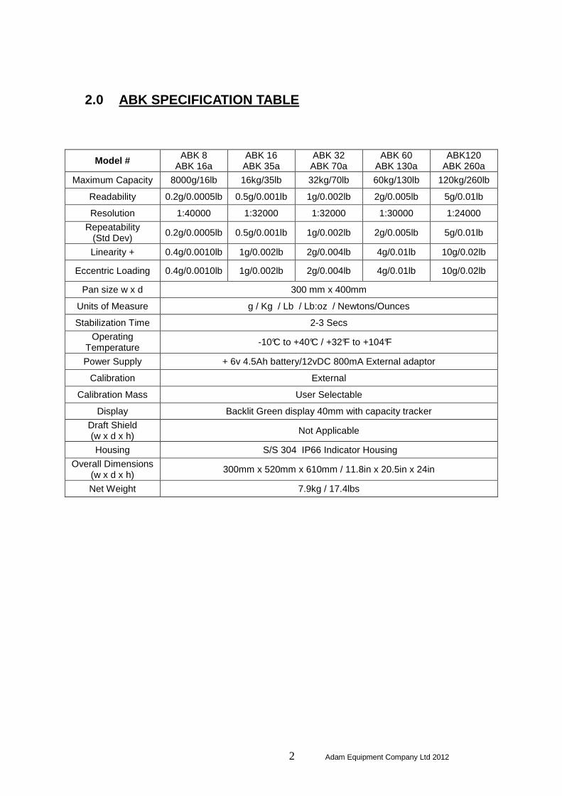
Model # ABK 8 ABK 16a
ABK 16 ABK 35a
ABK 32 ABK 70a
ABK 60 ABK 130a
ABK120 ABK 260a
Maximum Capacity 8000g/16lb 16kg/35lb 32kg/70lb 60kg/130lb 120kg/260lb
Readability 0.2g/0.0005lb 0.5g/0.001lb 1g/0.002lb 2g/0.005lb 5g/0.01lb
Resolution 1:40000 1:32000 1:32000 1:30000 1:24000
Repeatability (Std Dev)
0.2g/0.0005lb 0.5g/0.001lb 1g/0.002lb 2g/0.005lb 5g/0.01lb
Linearity + 0.4g/0.0010lb 1g/0.002lb 2g/0.004lb 4g/0.01lb 10g/0.02lb
Eccentric Loading 0.4g/0.0010lb 1g/0.002lb 2g/0.004lb 4g/0.01lb 10g/0.02lb
Pan size w x d 300 mm x 400mm
Units of Measure g / Kg / Lb / Lb:oz / Newtons/Ounces
Stabilization Time 2-3 Secs
Operating Temperature
-10°C to +40°C / +32°F to +104°F
Power Supply + 6v 4.5Ah battery/12vDC 800mA External adaptor
Calibration External
Calibration Mass User Selectable
Display Backlit Green display 40mm with capacity tracker
Draft Shield (w x d x h) Not Applicable
Housing S/S 304 IP66 Indicator Housing
Overall Dimensions (w x d x h)
300mm x 520mm x 610mm / 11.8in x 20.5in x 24in
Net Weight 7.9kg / 17.4lbs
2.0 ABK SPECIFICATION TABLE
3 Adam Equipment Company Ltd 2012
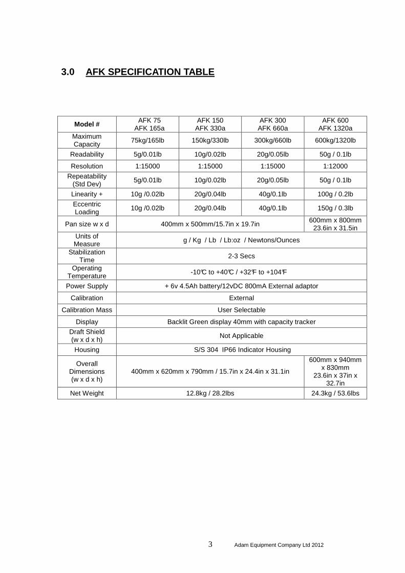
3.0 AFK SPECIFICATION TABLE
Model # AFK 75 AFK 165a
AFK 150 AFK 330a
AFK 300 AFK 660a
AFK 600 AFK 1320a
Maximum Capacity
75kg/165lb 150kg/330lb 300kg/660lb 600kg/1320lb
Readability 5g/0.01lb 10g/0.02lb 20g/0.05lb 50g / 0.1lb
Resolution 1:15000 1:15000 1:15000 1:12000
Repeatability (Std Dev)
5g/0.01lb 10g/0.02lb 20g/0.05lb 50g / 0.1lb
Linearity + 10g /0.02lb 20g/0.04lb 40g/0.1lb 100g / 0.2lb
Eccentric Loading
10g /0.02lb 20g/0.04lb 40g/0.1lb 150g / 0.3lb
Pan size w x d 400mm x 500mm/15.7in x 19.7in 600mm x 800mm
23.6in x 31.5in Units of Measure g / Kg / Lb / Lb:oz / Newtons/Ounces
Stabilization Time
2-3 Secs
Operating Temperature
-10°C to +40°C / +32°F to +104°F
Power Supply + 6v 4.5Ah battery/12vDC 800mA External adaptor
Calibration External
Calibration Mass User Selectable
Display Backlit Green display 40mm with capacity tracker
Draft Shield (w x d x h)
Not Applicable
Housing S/S 304 IP66 Indicator Housing
Overall Dimensions (w x d x h)
400mm x 620mm x 790mm / 15.7in x 24.4in x 31.1in
600mm x 940mm x 830mm
23.6in x 37in x 32.7in
Net Weight 12.8kg / 28.2lbs 24.3kg / 53.6lbs
4 Adam Equipment Company Ltd 2012
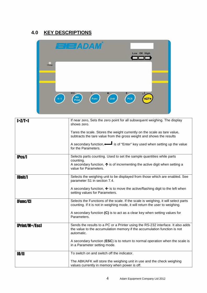
[>Z/T<]
If near zero, Sets the zero point for all subsequent weighing. The display shows zero. Tares the scale. Stores the weight currently on the scale as tare value, subtracts the tare value from the gross weight and shows the results A secondary function, is of “Enter” key used when setting up the value for the Parameters.
[Pcs/] Selects parts counting. Used to set the sample quantities while parts counting. A secondary function, ���� is of incrementing the active digit when setting a value for Parameters.
[Unit/]
Selects the weighing unit to be displayed from those which are enabled. See parameter S1 in section 7.4. A secondary function, is to move the active/flashing digit to the left when setting values for Parameters.
[Func/C]
Selects the Functions of the scale. If the scale is weighing, it will select parts counting. If it is not in weighing mode, it will return the user to weighing. A secondary function (C) is to act as a clear key when setting values for Parameters.
[Print/M+/Esc]
Sends the results to a PC or a Printer using the RS-232 interface. It also adds the value to the accumulation memory if the accumulation function is not automatic. A secondary function (ESC) is to return to normal operation when the scale is in a Parameter setting mode.
[O/I]
To switch on and switch off the indicator. The ABK/AFK will store the weighing unit in use and the check weighing values currently in memory when power is off.
4.0 KEY DESCRIPTIONS
5 Adam Equipment Company Ltd 2012
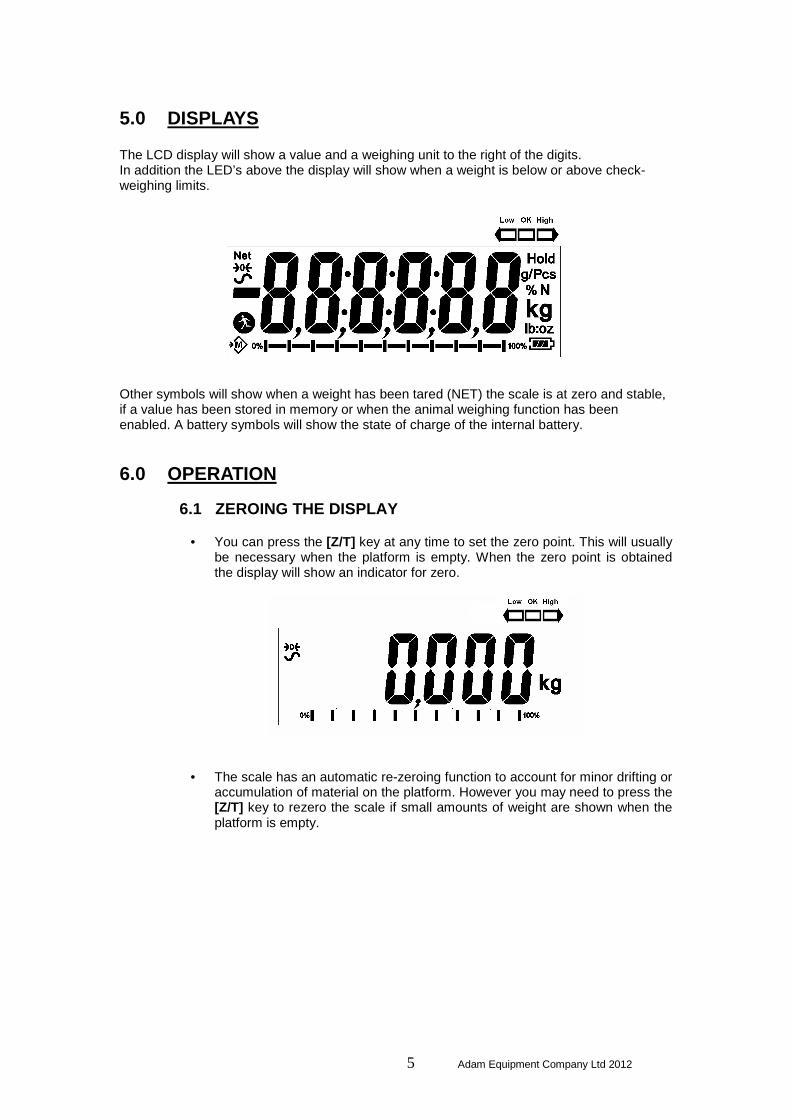
The LCD display will show a value and a weighing unit to the right of the digits. In addition the LED’s above the display will show when a weight is below or above check-weighing limits.
Other symbols will show when a weight has been tared (NET) the scale is at zero and stable, if a value has been stored in memory or when the animal weighing function has been enabled. A battery symbols will show the state of charge of the internal battery.
6.1 ZEROING THE DISPLAY
• You can press the [Z/T] key at any time to set the zero point. This will usually
be necessary when the platform is empty. When the zero point is obtained the display will show an indicator for zero.
• The scale has an automatic re-zeroing function to account for minor drifting or accumulation of material on the platform. However you may need to press the [Z/T] key to rezero the scale if small amounts of weight are shown when the platform is empty.
5.0 DISPLAYS
6.0 OPERATION
6 Adam Equipment Company Ltd 2012
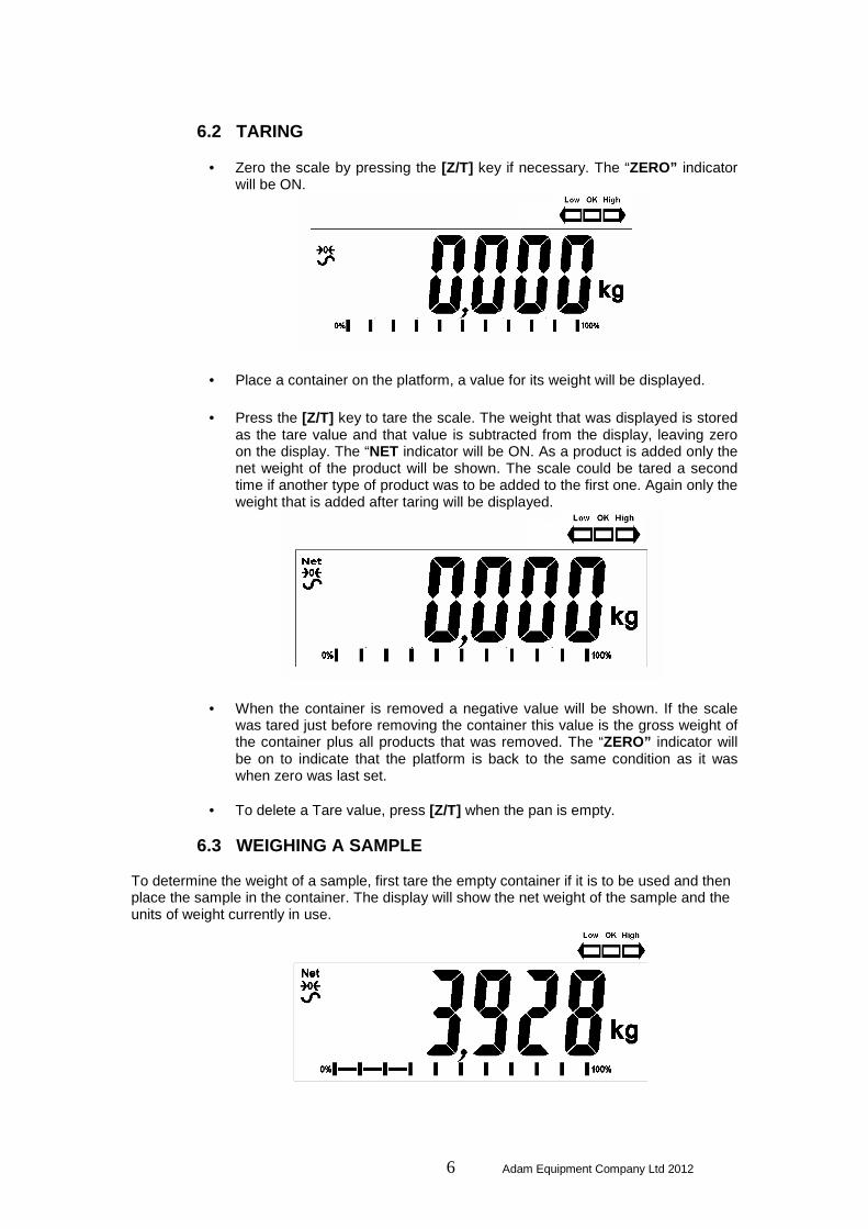
6.2 TARING
• Zero the scale by pressing the [Z/T] key if necessary. The “ZERO” indicator
will be ON.
• Place a container on the platform, a value for its weight will be displayed.
• Press the [Z/T] key to tare the scale. The weight that was displayed is stored as the tare value and that value is subtracted from the display, leaving zero on the display. The “NET indicator will be ON. As a product is added only the net weight of the product will be shown. The scale could be tared a second time if another type of product was to be added to the first one. Again only the weight that is added after taring will be displayed.
• When the container is removed a negative value will be shown. If the scale was tared just before removing the container this value is the gross weight of the container plus all products that was removed. The “ZERO” indicator will be on to indicate that the platform is back to the same condition as it was when zero was last set.
• To delete a Tare value, press [Z/T] when the pan is empty.
6.3 WEIGHING A SAMPLE
To determine the weight of a sample, first tare the empty container if it is to be used and then place the sample in the container. The display will show the net weight of the sample and the units of weight currently in use.
7 Adam Equipment Company Ltd 2012
6.4 PARTS COUNTING
If parts counting is enabled, See section 7.4, it is possible to count parts using a sample of the parts to determine average piece weight.
• Before starting, tare the weight of any container that may be used, leaving the empty container on the scale. Place a known number of samples in the container, if used. The number should match the options for parts counting, i.e., 10, 20, 50, 100 or 200 pieces.
• When the scale is showing weight, pressing the [Pcs] key will start the parts
counting function.
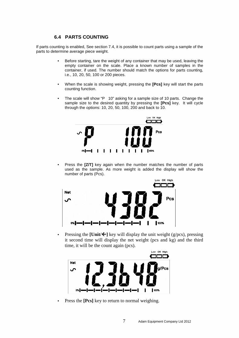
• The scale will show “P 10” asking for a sample size of 10 parts. Change the sample size to the desired quantity by pressing the [Pcs] key. It will cycle through the options: 10, 20, 50, 100, 200 and back to 10.
• Press the [Z/T] key again when the number matches the number of parts used as the sample. As more weight is added the display will show the number of parts (Pcs).
• Pressing the [Unit/] key will display the unit weight (g/pcs), pressing
it second time will display the net weight (pcs and kg) and the third time, it will be the count again (pcs).
• Press the [Pcs] key to return to normal weighing.
8 Adam Equipment Company Ltd 2012
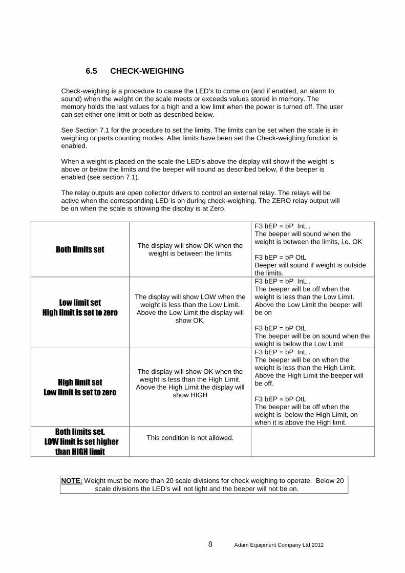
6.5 CHECK-WEIGHING Check-weighing is a procedure to cause the LED’s to come on (and if enabled, an alarm to sound) when the weight on the scale meets or exceeds values stored in memory. The memory holds the last values for a high and a low limit when the power is turned off. The user can set either one limit or both as described below. See Section 7.1 for the procedure to set the limits. The limits can be set when the scale is in weighing or parts counting modes. After limits have been set the Check-weighing function is enabled. When a weight is placed on the scale the LED’s above the display will show if the weight is above or below the limits and the beeper will sound as described below, if the beeper is enabled (see section 7.1). The relay outputs are open collector drivers to control an external relay. The relays will be active when the corresponding LED is on during check-weighing. The ZERO relay output will be on when the scale is showing the display is at Zero.
Both limits set The display will show OK when the
weight is between the limits
F3 bEP = bP InL . The beeper will sound when the weight is between the limits, i.e. OK F3 bEP = bP OtL Beeper will sound if weight is outside the limits.
Low limit set
High limit is set to zero
The display will show LOW when the weight is less than the Low Limit.
Above the Low Limit the display will show OK,
F3 bEP = bP InL . The beeper will be off when the weight is less than the Low Limit. Above the Low Limit the beeper will be on F3 bEP = bP OtL The beeper will be on sound when the weight is below the Low Limit
High limit set
Low limit is set to zero
The display will show OK when the weight is less than the High Limit.
Above the High Limit the display will show HIGH
F3 bEP = bP InL . The beeper will be on when the weight is less than the High Limit. Above the High Limit the beeper will be off. F3 bEP = bP OtL The beeper will be off when the weight is below the High Limit, on when it is above the High limit.
Both limits set.
LOW limit is set higher
than HIGH limit
This condition is not allowed.
NOTE: Weight must be more than 20 scale divisions for check weighing to operate. Below 20
scale divisions the LED’s will not light and the beeper will not be on.
9 Adam Equipment Company Ltd 2012
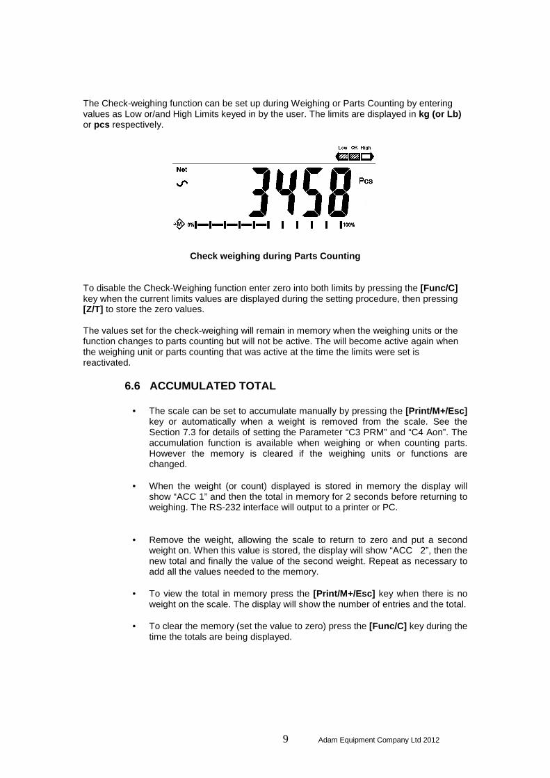
The Check-weighing function can be set up during Weighing or Parts Counting by entering values as Low or/and High Limits keyed in by the user. The limits are displayed in kg (or Lb) or pcs respectively.
Check weighing during Parts Counting
To disable the Check-Weighing function enter zero into both limits by pressing the [Func/C] key when the current limits values are displayed during the setting procedure, then pressing [Z/T] to store the zero values. The values set for the check-weighing will remain in memory when the weighing units or the function changes to parts counting but will not be active. The will become active again when the weighing unit or parts counting that was active at the time the limits were set is reactivated.
6.6 ACCUMULATED TOTAL
• The scale can be set to accumulate manually by pressing the [Print/M+/Esc] key or automatically when a weight is removed from the scale. See the Section 7.3 for details of setting the Parameter “C3 PRM” and “C4 Aon”. The accumulation function is available when weighing or when counting parts. However the memory is cleared if the weighing units or functions are changed.
• When the weight (or count) displayed is stored in memory the display will
show “ACC 1” and then the total in memory for 2 seconds before returning to weighing. The RS-232 interface will output to a printer or PC.
• Remove the weight, allowing the scale to return to zero and put a second weight on. When this value is stored, the display will show “ACC 2”, then the new total and finally the value of the second weight. Repeat as necessary to add all the values needed to the memory.
• To view the total in memory press the [Print/M+/Esc] key when there is no
weight on the scale. The display will show the number of entries and the total. • To clear the memory (set the value to zero) press the [Func/C] key during the
time the totals are being displayed.
10 Adam Equipment Company Ltd 2012
6.7 PERCENT WEIGHING
The scale can be set to perform percent weighing. See Section 7.2. The scale will use a mass on the platform as the 100% reference weight. If the platform is empty (or the scale is tared) then the user can input a reference weight using the keypad.
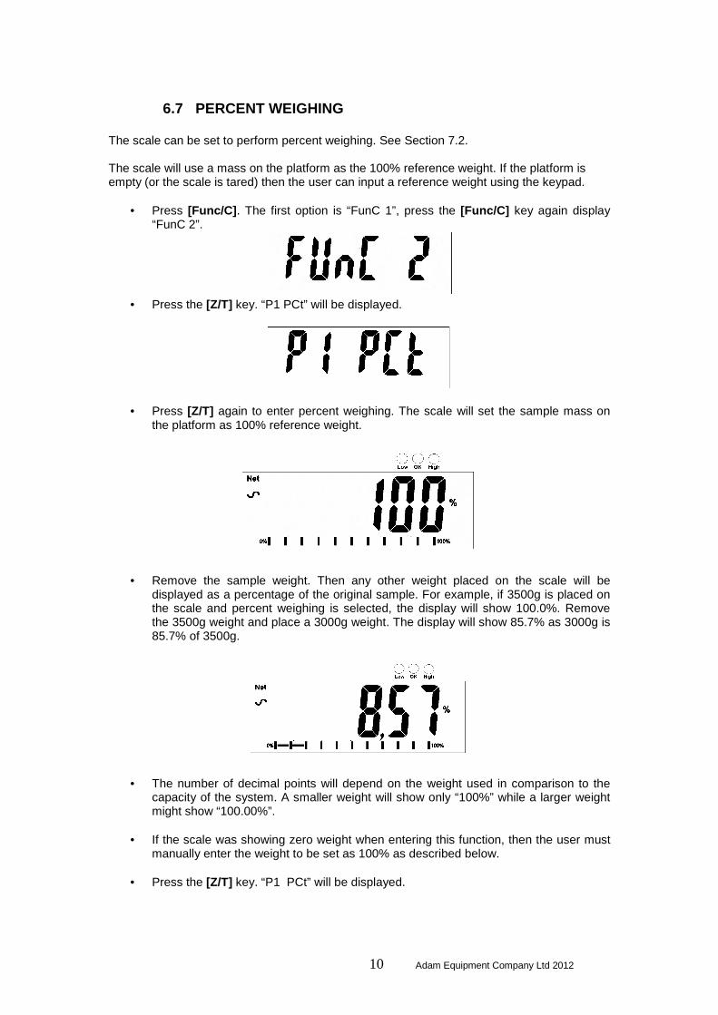
• Press [Func/C] . The first option is “FunC 1”, press the [Func/C] key again display “FunC 2”.
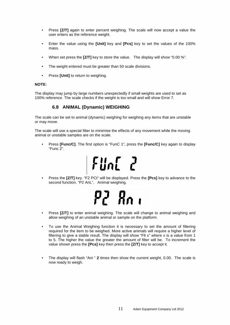
• Press the [Z/T] key. “P1 PCt” will be displayed.
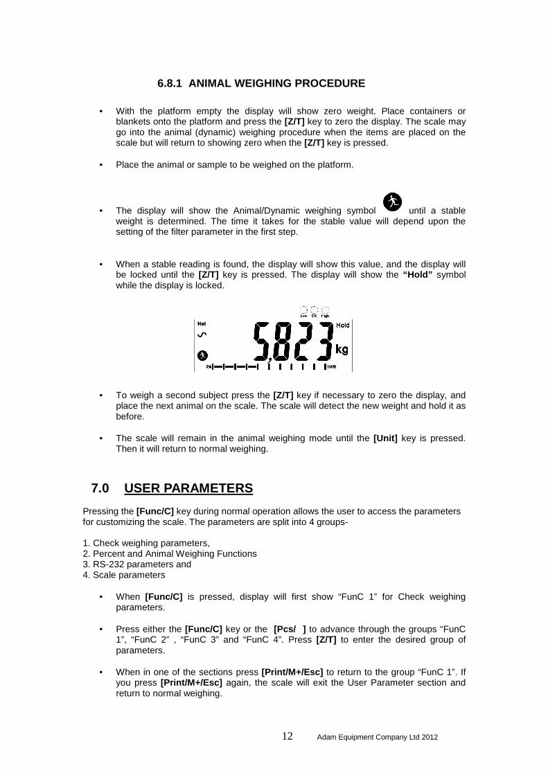
• Press [Z/T] again to enter percent weighing. The scale will set the sample mass on the platform as 100% reference weight.
• Remove the sample weight. Then any other weight placed on the scale will be displayed as a percentage of the original sample. For example, if 3500g is placed on the scale and percent weighing is selected, the display will show 100.0%. Remove the 3500g weight and place a 3000g weight. The display will show 85.7% as 3000g is 85.7% of 3500g.
• The number of decimal points will depend on the weight used in comparison to the capacity of the system. A smaller weight will show only “100%” while a larger weight might show “100.00%”.
• If the scale was showing zero weight when entering this function, then the user must
manually enter the weight to be set as 100% as described below.
• Press the [Z/T] key. “P1 PCt” will be displayed.
11 Adam Equipment Company Ltd 2012
• Press [Z/T] again to enter percent weighing. The scale will now accept a value the user enters as the reference weight.
• Enter the value using the [Unit] key and [Pcs] key to set the values of the 100%
mass.
• When set press the [Z/T] key to store the value. The display will show “0.00 %”.
• The weight entered must be greater than 50 scale divisions.
• Press [Unit] to return to weighing. NOTE: The display may jump by large numbers unexpectedly if small weights are used to set as 100% reference. The scale checks if the weight is too small and will show Error 7.
6.8 ANIMAL (Dynamic) WEIGHING The scale can be set to animal (dynamic) weighing for weighing any items that are unstable or may move. The scale will use a special filter to minimise the effects of any movement while the moving animal or unstable samples are on the scale.
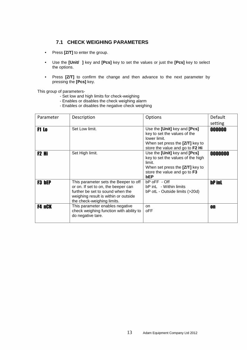
• Press [Func/C] . The first option is “FunC 1”, press the [Func/C] key again to display “Func 2”.
• Press the [Z/T] key. “F2 PCt” will be displayed. Press the [Pcs] key to advance to the
second function, “P2 AnL”, Animal weighing.
• Press [Z/T] to enter animal weighing. The scale will change to animal weighing and
allow weighing of an unstable animal or sample on the platform.
• To use the Animal Weighing function it is necessary to set the amount of filtering required for the item to be weighed. More active animals will require a higher level of filtering to give a stable result. The display will show “Flt x” where x is a value from 1 to 5. The higher the value the greater the amount of filter will be. To increment the value shown press the [Pcs] key then press the [Z/T] key to accept it.
• The display will flash “Ani “ 2 times then show the current weight, 0.00. The scale is now ready to weigh.
12 Adam Equipment Company Ltd 2012
6.8.1 ANIMAL WEIGHING PROCEDURE
• With the platform empty the display will show zero weight. Place containers or blankets onto the platform and press the [Z/T] key to zero the display. The scale may go into the animal (dynamic) weighing procedure when the items are placed on the scale but will return to showing zero when the [Z/T] key is pressed.
• Place the animal or sample to be weighed on the platform.
• The display will show the Animal/Dynamic weighing symbol until a stable weight is determined. The time it takes for the stable value will depend upon the setting of the filter parameter in the first step.
• When a stable reading is found, the display will show this value, and the display will be locked until the [Z/T] key is pressed. The display will show the “Hold” symbol while the display is locked.
• To weigh a second subject press the [Z/T] key if necessary to zero the display, and place the next animal on the scale. The scale will detect the new weight and hold it as before.
• The scale will remain in the animal weighing mode until the [Unit] key is pressed.
Then it will return to normal weighing.
Pressing the [Func/C] key during normal operation allows the user to access the parameters for customizing the scale. The parameters are split into 4 groups- 1. Check weighing parameters, 2. Percent and Animal Weighing Functions 3. RS-232 parameters and 4. Scale parameters
• When [Func/C] is pressed, display will first show “FunC 1” for Check weighing parameters.
• Press either the [Func/C] key or the [Pcs/�] to advance through the groups “FunC
1”, “FunC 2” , “FunC 3” and “FunC 4”. Press [Z/T] to enter the desired group of parameters.
• When in one of the sections press [Print/M+/Esc] to return to the group “FunC 1”. If
you press [Print/M+/Esc] again, the scale will exit the User Parameter section and return to normal weighing.
7.0 USER PARAMETERS
13 Adam Equipment Company Ltd 2012
7.1 CHECK WEIGHING PARAMETERS
• Press [Z/T] to enter the group.
• Use the [Unit/�] key and [Pcs] key to set the values or just the [Pcs] key to select the options.
• Press [Z/T] to confirm the change and then advance to the next parameter by
pressing the [Pcs] key. This group of parameters-
- Set low and high limits for check-weighing - Enables or disables the check weighing alarm - Enables or disables the negative check weighing
Parameter Description Options Default
setting
F1 Lo Set Low limit.
Use the [Unit] key and [Pcs] key to set the values of the lower limit. When set press the [Z/T] key to store the value and go to F2 Hi
000000
F2 Hi Set High limit.
Use the [Unit] key and [Pcs] key to set the values of the high limit. When set press the [Z/T] key to store the value and go to F3 bEP
0000000
F3 bEP This parameter sets the Beeper to off or on. If set to on, the beeper can further be set to sound when the weighing result is within or outside the check-weighing limits.
bP oFF - Off bP inL - Within limits bP otL - Outside limits (>20d)
bP inL
F4 nCK This parameter enables negative check weighing function with ability to do negative tare.
on oFF
on
14 Adam Equipment Company Ltd 2012
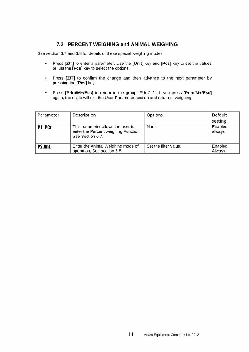
7.2 PERCENT WEIGHING and ANIMAL WEIGHING
See section 6.7 and 6.8 for details of these special weighing modes.
• Press [Z/T] to enter a parameter. Use the [Unit] key and [Pcs] key to set the values or just the [Pcs] key to select the options.
• Press [Z/T] to confirm the change and then advance to the next parameter by
pressing the [Pcs] key. • Press [Print/M+/Esc] to return to the group “FUnC 2”. If you press [Print/M+/Esc]
again, the scale will exit the User Parameter section and return to weighing. Parameter Description Options Default
setting
P1 PCt
This parameter allows the user to enter the Percent weighing Function. See Section 6.7.
None Enabled always
P2 AnL Enter the Animal Weighing mode of operation, See section 6.8
Set the filter value. Enabled Always
15 Adam Equipment Company Ltd 2012
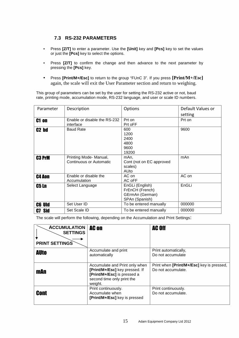
7.3 RS-232 PARAMETERS
• Press [Z/T] to enter a parameter. Use the [Unit] key and [Pcs] key to set the values
or just the [Pcs] key to select the options.
• Press [Z/T] to confirm the change and then advance to the next parameter by pressing the [Pcs] key.
• Press [Print/M+/Esc] to return to the group “FUnC 3”. If you press [Print/M+/Esc]
again, the scale will exit the User Parameter section and return to weighing. This group of parameters can be set by the user for setting the RS-232 active or not, baud rate, printing mode, accumulation mode, RS-232 language, and user or scale ID numbers. Parameter Description Options Default Values or
setting
C1 on Enable or disable the RS-232 interface
Prt on Prt oFF
Prt on
C2 bd Baud Rate
600 1200 2400 4800 9600 19200
9600
C3 PrM Printing Mode- Manual, Continuous or Automatic
mAn, Cont (not on EC approved scales) AUto
mAn
C4 Aon Enable or disable the Accumulation
AC on AC oFF
AC on
C5 Ln Select Language EnGLi (English) FrEnCH (French) GErmAn (German) SPAn (Spanish)
EnGLi
C6 UId Set User ID To be entered manually 000000
C7 Sid Set Scale ID To be entered manually 000000
The scale will perform the following, depending on the Accumulation and Print Settings:
ACCUMULATION SETTINGS
PRINT SETTINGS
AC on AC Off
AUto
Accumulate and print automatically
Print automatically, Do not accumulate
mAn
Accumulate and Print only when [Print/M+/Esc] key pressed. If [Print/M+/Esc] is pressed a second time only print the weight.
Print when [Print/M+/Esc] key is pressed, Do not accumulate.
Cont
Print continuously. Accumulate when [Print/M+/Esc] key is pressed
Print continuously. Do not accumulate.
16 Adam Equipment Company Ltd 2012
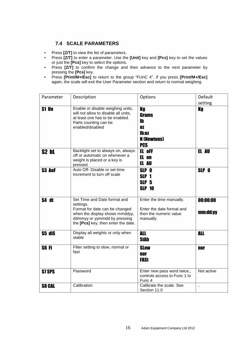
7.4 SCALE PARAMETERS
• Press [Z/T] to view the list of parameters. • Press [Z/T] to enter a parameter. Use the [Unit] key and [Pcs] key to set the values
or just the [Pcs] key to select the options. • Press [Z/T] to confirm the change and then advance to the next parameter by
pressing the [Pcs] key. • Press [Print/M+/Esc] to return to the group “FUnC 4”. If you press [Print/M+/Esc]
again, the scale will exit the User Parameter section and return to normal weighing.
Parameter Description Options Default
setting
S1 Un Enable or disable weighing units, will not allow to disable all units, at least one has to be enabled. Parts counting can be enabled/disabled
Kg
Grams
lb
oz
lb:oz
N (Newtons)
PCS
Kg
S2 bL Backlight set to always on, always off or automatic on whenever a weight is placed or a key is pressed
EL oFF EL on EL AU
EL AU
S3 AoF Auto Off- Disable or set time increment to turn off scale
SLP 0
SLP 1
SLP 5
SLP 10
SLP 0
S4 dt Set Time and Date format and settings. Format for date can be changed when the display shows mmddyy, ddmmyy or yymmdd by pressing the [Pcs] key, then enter the date.
Enter the time manually. Enter the date format and then the numeric value manually.
00:00:00
mm:dd:yy
S5 diS Display all weights or only when stable
ALL
StAb ALL
S6 Fi Filter setting to slow, normal or fast
SLow
nor
FASt
nor
S7 SPS Password Enter new pass word twice,, controls access to Func 1 to Func 4
Not active
S8 CAL Calibration Calibrate the scale. See Section 11.0
-
17 Adam Equipment Company Ltd 2012
• The scales can be operated from the battery if desired. The battery life can be up to 70 hours depending on the load cells and how the backlight is used.
• A battery symbol is shown on the display which indicates the current charge of the battery, 3 bars means fully charged. When just the outline of the battery and no bars are visible the battery needs to be re charged.
• To charge the battery, simply plug the adaptor into the mains power, and also into the input connector on the rear of the Indicator marked DC 12V. The scale does not need to be turned on.
• The battery should be charged for 12 hours to reach full capacity. • Near the display is an LED to indicate the status of battery charging. When
the scale is plugged into the mains power the internal battery will be charged. When the LED is green the battery has a full charge.
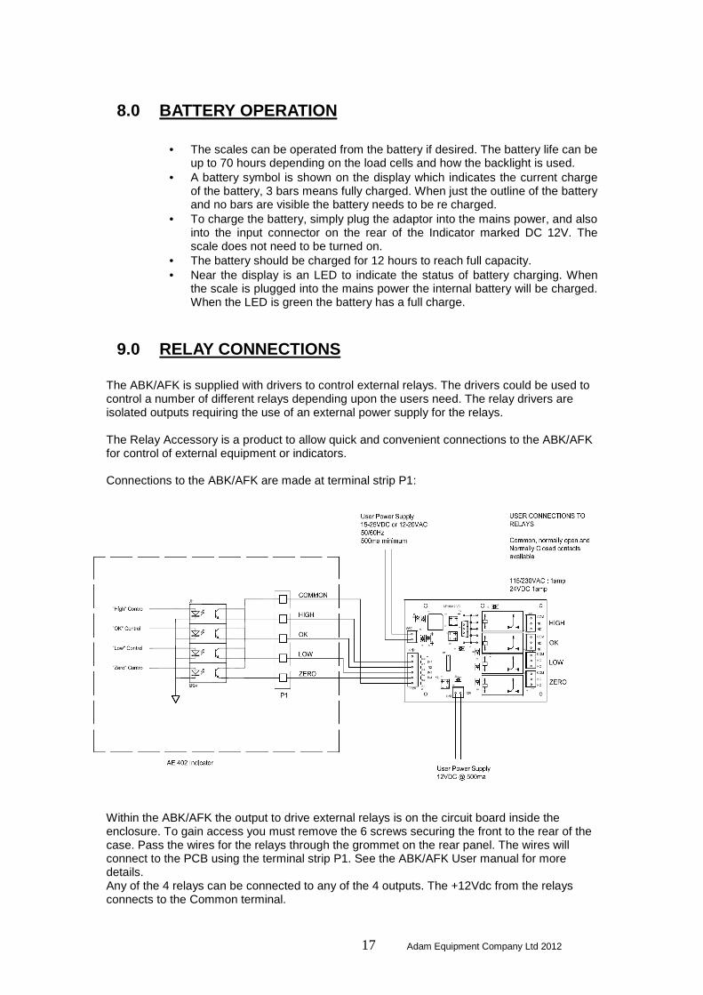
The ABK/AFK is supplied with drivers to control external relays. The drivers could be used to control a number of different relays depending upon the users need. The relay drivers are isolated outputs requiring the use of an external power supply for the relays. The Relay Accessory is a product to allow quick and convenient connections to the ABK/AFK for control of external equipment or indicators. Connections to the ABK/AFK are made at terminal strip P1:
Within the ABK/AFK the output to drive external relays is on the circuit board inside the enclosure. To gain access you must remove the 6 screws securing the front to the rear of the case. Pass the wires for the relays through the grommet on the rear panel. The wires will connect to the PCB using the terminal strip P1. See the ABK/AFK User manual for more details. Any of the 4 relays can be connected to any of the 4 outputs. The +12Vdc from the relays connects to the Common terminal.
8.0 BATTERY OPERATION
9.0 RELAY CONNECTIONS
18 Adam Equipment Company Ltd 2012
3
12
4
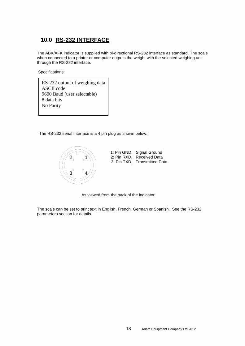
The ABK/AFK indicator is supplied with bi-directional RS-232 interface as standard. The scale when connected to a printer or computer outputs the weight with the selected weighing unit through the RS-232 interface. Specifications:
The RS-232 serial interface is a 4 pin plug as shown below:
1: Pin GND, Signal Ground 2: Pin RXD, Received Data
3: Pin TXD, Transmitted Data
As viewed from the back of the indicator
The scale can be set to print text in English, French, German or Spanish. See the RS-232 parameters section for details.
10.0 RS-232 INTERFACE
RS-232 output of weighing data ASCII code 9600 Baud (user selectable) 8 data bits No Parity
19 Adam Equipment Company Ltd 2012
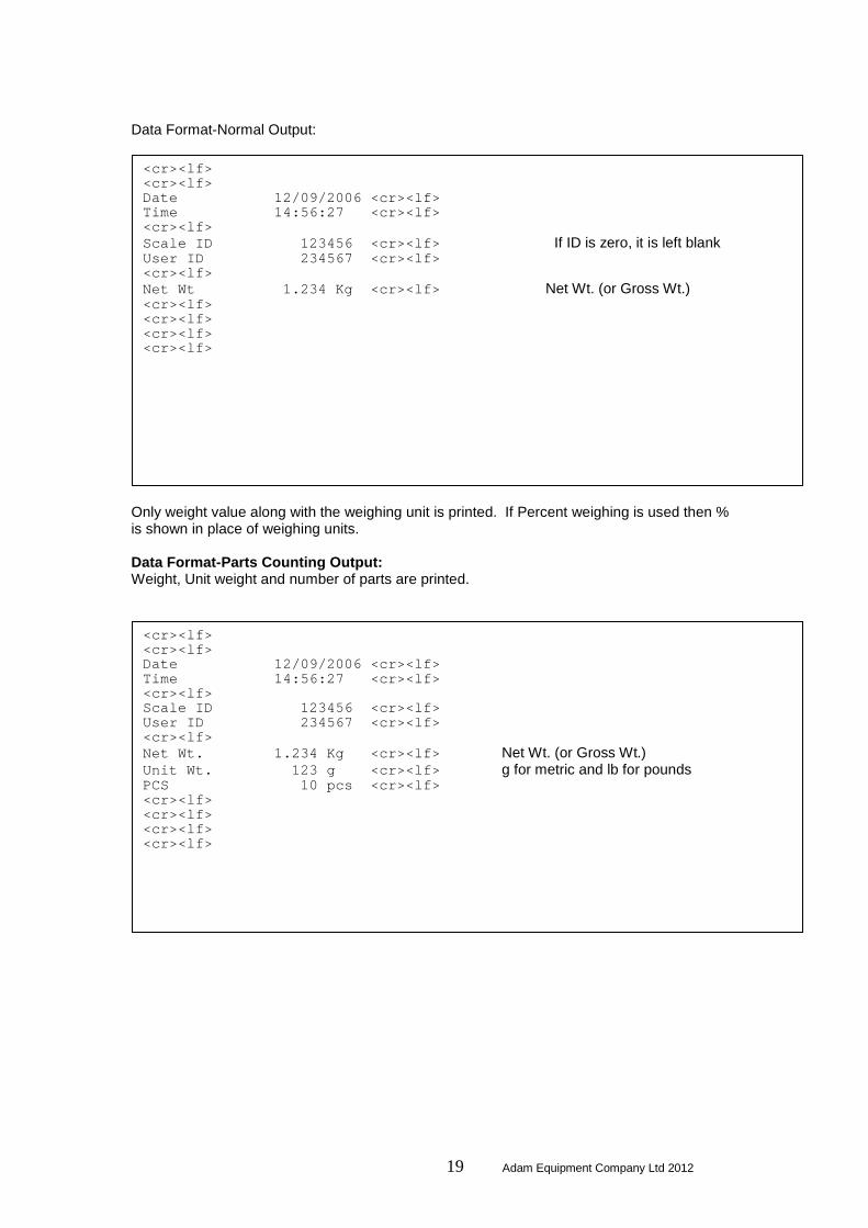
Data Format-Normal Output:
Only weight value along with the weighing unit is printed. If Percent weighing is used then % is shown in place of weighing units. Data Format-Parts Counting Output: Weight, Unit weight and number of parts are printed.
<cr><lf> <cr><lf> Date 12/09/2006 <cr><lf> Time 14:56:27 <cr><lf> <cr><lf> Scale ID 123456 <cr><lf> User ID 234567 <cr><lf> <cr><lf> Net Wt. 1.234 Kg <cr><lf> Net Wt. (or Gross Wt.) Unit Wt. 123 g <cr><lf> g for metric and lb for pounds PCS 10 pcs <cr><lf> <cr><lf> <cr><lf> <cr><lf> <cr><lf>
<cr><lf> <cr><lf> Date 12/09/2006 <cr><lf> Time 14:56:27 <cr><lf> <cr><lf> Scale ID 123456 <cr><lf> If ID is zero, it is left blank User ID 234567 <cr><lf> <cr><lf> Net Wt 1.234 Kg <cr><lf> Net Wt. (or Gross Wt.) <cr><lf> <cr><lf> <cr><lf> <cr><lf>
20 Adam Equipment Company Ltd 2012
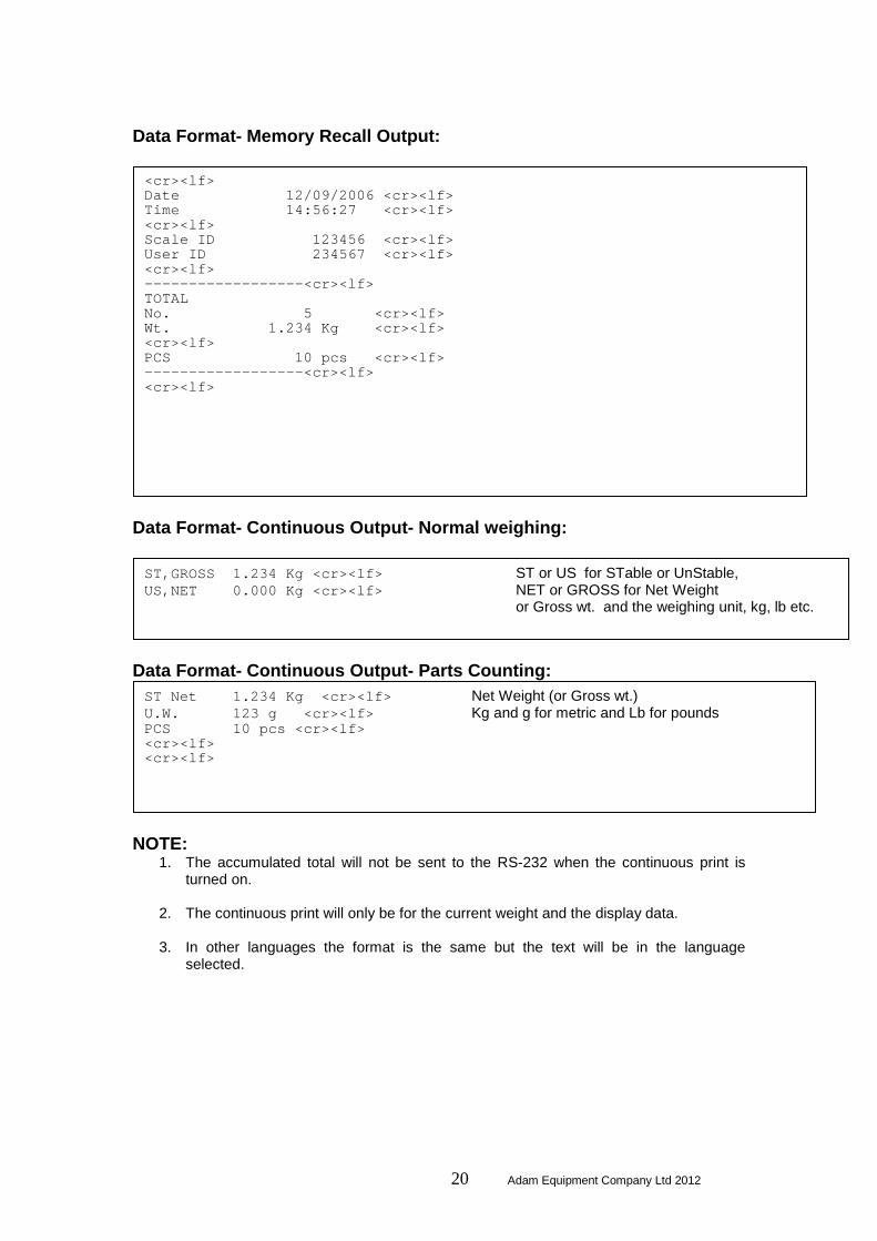
Data Format- Memory Recall Output:
Data Format- Continuous Output- Normal weighing:
Data Format- Continuous Output- Parts Counting:
NOTE:
1. The accumulated total will not be sent to the RS-232 when the continuous print is turned on.
2. The continuous print will only be for the current weight and the display data.
3. In other languages the format is the same but the text will be in the language
selected.
<cr><lf> Date 12/09/2006 <cr><lf> Time 14:56:27 <cr><lf> <cr><lf> Scale ID 123456 <cr><lf> User ID 234567 <cr><lf> <cr><lf> ------------------<cr><lf> TOTAL No. 5 <cr><lf> Wt. 1.234 Kg <cr><lf> <cr><lf> PCS 10 pcs <cr><lf> ------------------<cr><lf> <cr><lf>
ST,GROSS 1.234 Kg <cr><lf> ST or US for STable or UnStable, US,NET 0.000 Kg <cr><lf> NET or GROSS for Net Weight
or Gross wt. and the weighing unit, kg, lb etc.
ST Net 1.234 Kg <cr><lf> Net Weight (or Gross wt.) U.W. 123 g <cr><lf> Kg and g for metric and Lb for pounds PCS 10 pcs <cr><lf> <cr><lf> <cr><lf>
21 Adam Equipment Company Ltd 2012
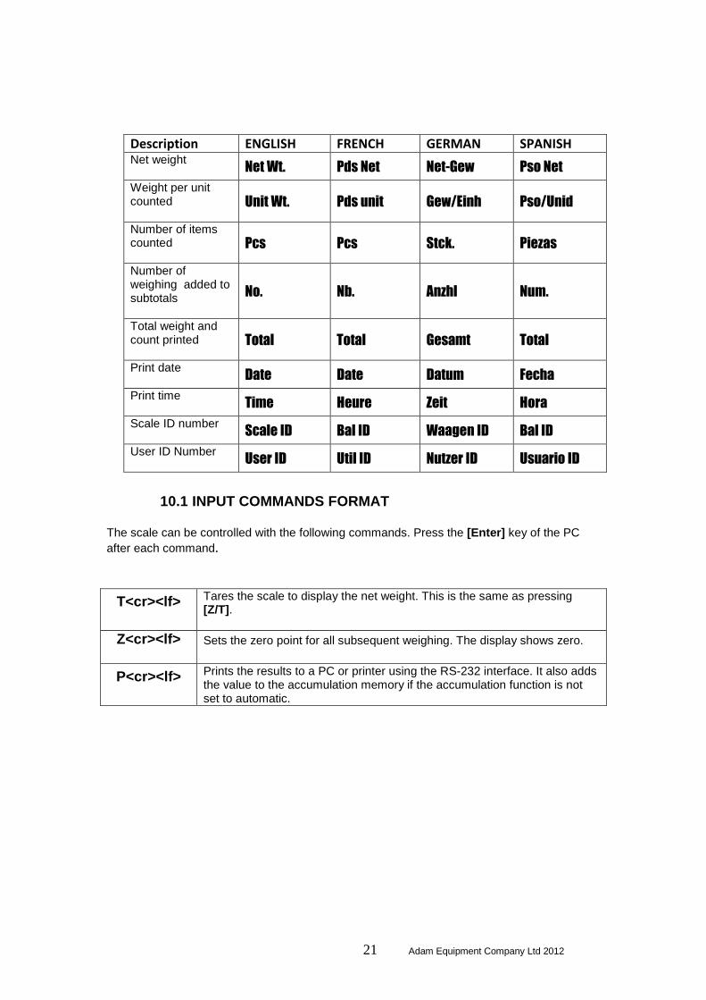
Description ENGLISH FRENCH GERMAN SPANISH
Net weight Net Wt. Pds Net Net-Gew Pso Net
Weight per unit counted
Unit Wt. Pds unit Gew/Einh Pso/Unid
Number of items counted
Pcs Pcs Stck. Piezas
Number of weighing added to subtotals
No. Nb. Anzhl Num.
Total weight and count printed
Total Total Gesamt Total
Print date Date Date Datum Fecha
Print time Time Heure Zeit Hora
Scale ID number Scale ID Bal ID Waagen ID Bal ID
User ID Number User ID Util ID Nutzer ID Usuario ID
10.1 INPUT COMMANDS FORMAT
The scale can be controlled with the following commands. Press the [Enter] key of the PC after each command.
T<cr><lf>
Tares the scale to display the net weight. This is the same as pressing [Z/T] .
Z<cr><lf>
Sets the zero point for all subsequent weighing. The display shows zero.
P<cr><lf>
Prints the results to a PC or printer using the RS-232 interface. It also adds the value to the accumulation memory if the accumulation function is not set to automatic.
22 Adam Equipment Company Ltd 2012
The scale can be calibrated using the following procedure. To enter this procedure it is necessary to use Func 4 accessible using the [Func/C] key as described in section 7.4 or using the password access as described in section 12. The ABK/AFK scales calibrate using either metric or pound weights, depending on the weighing unit in use before calibration. The display will show either "kg" or "lb" to identify the weights expected.
PROCEDURE
• Enter the calibration section using Func 4, C8 CAL or using the password as described in section 12.
• The display will show "unLoAd".
• Remove any weight from platform, when the stable symbol is on press [Z/T] .
• The display will show "Ld" the “0000XX” to show the last calibration weight used. Place this calibration weight on the scale. Press the [Z/T] key. If the weight you put on the scale does not match the value displayed, press the [Func/C] key to clear the vale then use the [Unit] key and [Pcs] key to set the correct value. When it is correct press [Z/T] .
• If the calibration is acceptable the scale will run a self-test during which the calibration weight should be removed. If an error message “FAiL L” is shown try calibration again as a disturbance may have prevented a successful calibration.
After calibration the scale should be checked to verify the calibration is correct. If necessary repeat calibration, make sure that the scale is stable before accepting any weight.
11.0 CALIBRATION
23 Adam Equipment Company Ltd 2012
The scales will allow entry to the parameters if the [Z/T] key is pressed during the power on cycle. In this case the display will show the passcode request screen, “ P - - - - “ . To continue enter a passcode using the [Unit] and [Pcs] keys. Entering passcode “0000” will allow calibration as shown in section 11. Entering passcode “1000” will allow access to a limited set of parameters described in section 12.2.
12.1 USING “0000” TO ENTER CALIBRATION MODE For a calibration, when “P - - - -“ is displayed enter the passcode “0000” and then press [Z/T] , follow the prompts as the table below shows to perform a calibration,
“P - - - -” When “P - - - -” is displayed. Enter “0000” and press [Z/T]
“UnLoAd ” Make sure the platform is empty and press [Z/T]
“LoAd” “X” “KiLoS” Load the requested calibration weight and press [Z/T]
“SPAn” “PASS” If Calibration is complete, “SPAn PASS” will be displayed. Remove the calibration weight.
Or, “SPAn” “FAiLEd ” This means calibration has failed. Remove the calibration weight and repeat the process.
12.2 USING “1000” TO ENTER THE SERVICE PARAMETERS When “P - - - -“ is displayed, enter the passcode “1000” and then press [Z/T] . The displays will show the first parameters, called “F4 Int”. To select another parameter press the [Pcs] key to advance through the parameters. Press the [Z/T] key to enter a parameter. To exit a parameter, press the [Print/M+/Esc] key. The display will show the parameter number and a name. When a parameter is entered by pressing the [Z/T] key, the displays will guide you through the parameter selected and the options available.
12.0 SERVICE SECTION
24 Adam Equipment Company Ltd 2012
The parameters available are: “F4 Int” Initial Zero Range
“F5 rEZ” Re-Zero range
“F6 SCS” Successive Tare Enable
“F7 Cnt” Display the A/D counts “F8 Zem” Zero Mode
“F9 Lvd” Low voltage detection “FA AZn” Auto Zero Range
“Fb FPS” User Function Password
12.2.1 F4 –INITIAL ZERO RANGE To enter this parameter, press the [Z/T] key when “F4 int” is shown. The display will show the current initial zero range. Press the [Pcs/] key to change the value and press [Z/T] to accept the value. Press [Print/M+/esc] to return to weighing.
12.2.2 F5 -RE-ZERO RANGE
To enter this parameter, press the [Z/T] key when “F5 rEZ” is shown. The display will show the current re-zero range. Press the [Pcs] key to change the value. Press [Z/T] to accept the value. Press [Print/M+/esc] to return to weighing.
12.2.3 F6 -SUCCESSIVE TARE
To enter this parameter, press the [Z/T] key when “F6 SCS” is shown. The display will show if the successive tare is on or off. Press the [Pcs] key to change the value. Press [Z/T] to accept the displayed value. Press [Print/M+/Esc] to return to weighing.
12.2.4 F7 –ADC COUNTS
To enter this parameter, press the [Z/T] key when “F7 Cnt” is shown. This parameter allows you to view the A/D counts from the internal A/D converter. This can be an aid to service. Press the [Z/T] key to return to the PARAMETER menu. Press the [Print/M+/Esc] key to return to weighing. Typical value at zero is 30,000-90,000 (approx.). Typical value at full capacity is 500,000 (approx.).
25 Adam Equipment Company Ltd 2012
12.2.5 F8 –ZERO MODE
To enter this parameter, press the [Z/T] key when “F8 ZEm” is shown. Select the Zero mode desired. In all but special cases Zero Mode 1 is used. The other 2 zero modes are for unique locations in the world and effect the +/- range of the zero. Press the [Pcs] key to change the value. Press [Z/T] to accept the displayed value. Press [Print/M+/Esc] to return to weighing.
12.2.6 F9 –LOW VOLTAGE DETECTION This parameter allows detection of low voltage when the battery wears down. To enter this parameter, press the [Z/T] key when “F9 LVd” is shown. The display will show if the LVD Mode is set to on or oFF. Press the [Pcs] key to change the value. Press [Z/T] to accept the displayed value. Press [Print/M+/Esc] to return to weighing.
12.2.7 FA –AZn AUTO ZERO RANGE This parameter sets the auto zero range from 0 (Off) to 4d. Calibration and parameter counting function to be active. To enter this parameter, press the [Z/T] key when “FA AZn” is shown. The display will show if the current Auto Zero range. Press the [Pcs] key to change the value. Press [Z/T] to accept the displayed value. Press [Print/M+/Esc] to return to weighing.
12.2.8 Fb –FPS USER FUNCTION PASSWORD This parameter set a password to control access to the user functions as described in Section 7. If the password is set to 0000 the control is disabled and the user has free access to the functions. To enter this parameter, press the [Z/T] key when “Fb FPS” is shown. The display will show “P1 - - - -“Enter the new password code followed by [Z/T] to accept.
The display will then show “P2 - - - -“Enter the new password code again followed by [Z/T] to accept. The same code number must be entered both times for the password to be set. Press the [Unit] and [Pcs] keys to enter the values. Press [Print/M+/Esc] to return to weighing.
26 Adam Equipment Company Ltd 2012
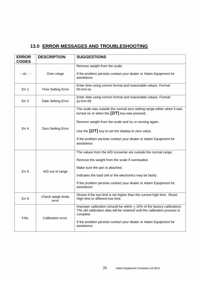
ERROR CODES
DESCRIPTION SUGGESTIONS
- -oL - - Over-range
Remove weight from the scale. If the problem persists contact your dealer or Adam Equipment for assistance.
Err 1 Time Setting Error Enter time using correct format and reasonable values. Format: hh:mm:ss
Err 2 Date Setting Error Enter date using correct format and reasonable values. Format: yy:mm:dd
Err 4 Zero Setting Error
The scale was outside the normal zero setting range either when it was turned on or when the [Z/T] key was pressed. Remove weight from the scale and try re-zeroing again. Use the [Z/T] key to set the display to zero value. If the problem persists contact your dealer or Adam Equipment for assistance.
Err 6 A/D out of range
The values from the A/D converter are outside the normal range. Remove the weight from the scale if overloaded. Make sure the pan is attached. Indicates the load cell or the electronics may be faulty. If the problem persists contact your dealer or Adam Equipment for assistance.
Err 9 Check weigh limits
error
Shown if the low limit is set higher than the current high limit. Reset High limit or different low limit.
FAIL Calibration error.
Improper calibration (should be within + 10% of the factory calibration). The old calibration data will be retained until the calibration process is complete. If the problem persists contact your dealer or Adam Equipment for assistance.
13.0 ERROR MESSAGES AND TROUBLESHOOTING
27 Adam Equipment Company Ltd 2012
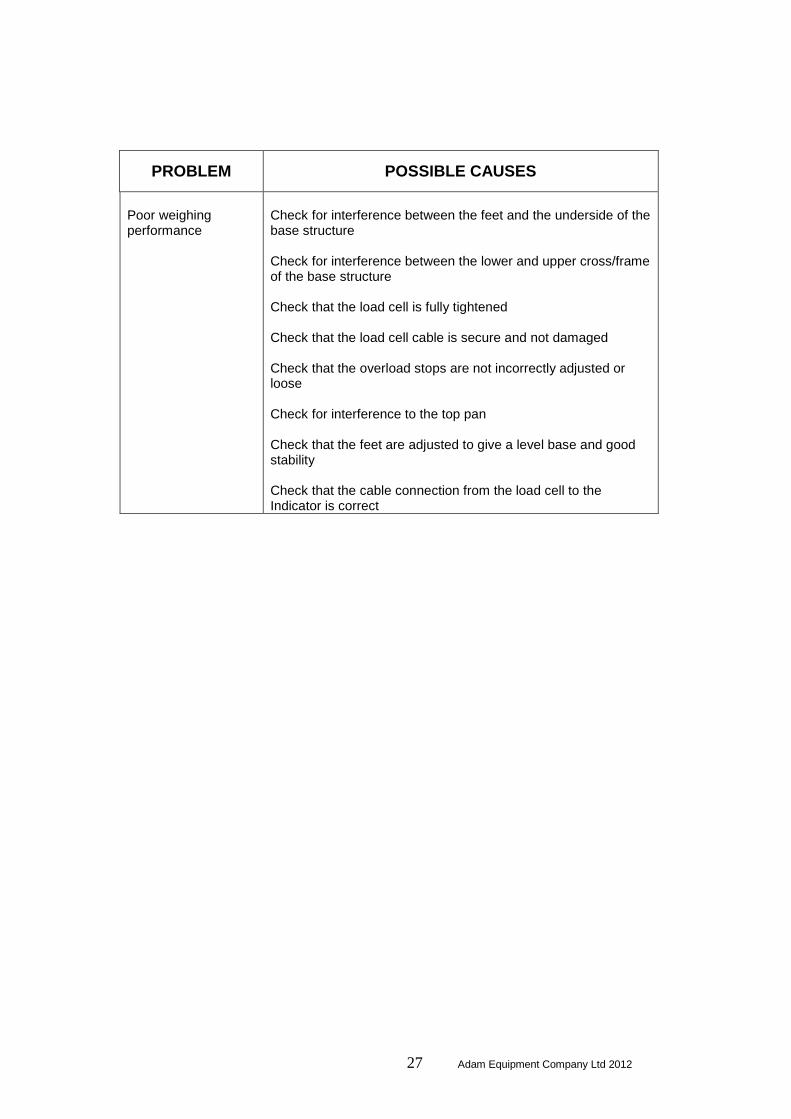
PROBLEM POSSIBLE CAUSES
Poor weighing performance
Check for interference between the feet and the underside of the base structure Check for interference between the lower and upper cross/frame of the base structure Check that the load cell is fully tightened Check that the load cell cable is secure and not damaged Check that the overload stops are not incorrectly adjusted or loose Check for interference to the top pan Check that the feet are adjusted to give a level base and good stability Check that the cable connection from the load cell to the Indicator is correct
28 Adam Equipment Company Ltd 2012
To evaluate that the load cell signal output is correct you can make certain measurements. The load cell functions using a 5Vdc input and this can be checked by placing two probes from a multi meter between the (exc +) and (exc-) cables where the load cell cable attaches to the 7 pin connector. If 5Vdc is present then power is being provided correctly to the load cell, the next step is to measure the output of the load cell, this can be done by placing the 2 probes between the (sig +) and (sig -) wires. In order to obtain an accurate reading the (sig +) and (sig -) wires may need to be detached (de-soldered) from the connector. You should expect to see a positive voltage reading of between 0 and 2 milli volts when the load cell assembly is at no load, and when a downward force is applied to the load cell assembly the reading should increase. If with no load a reading of more than 2 milli volts is recorded then this suggests damage to the load cell may have occurred and a replacement load cell is required.
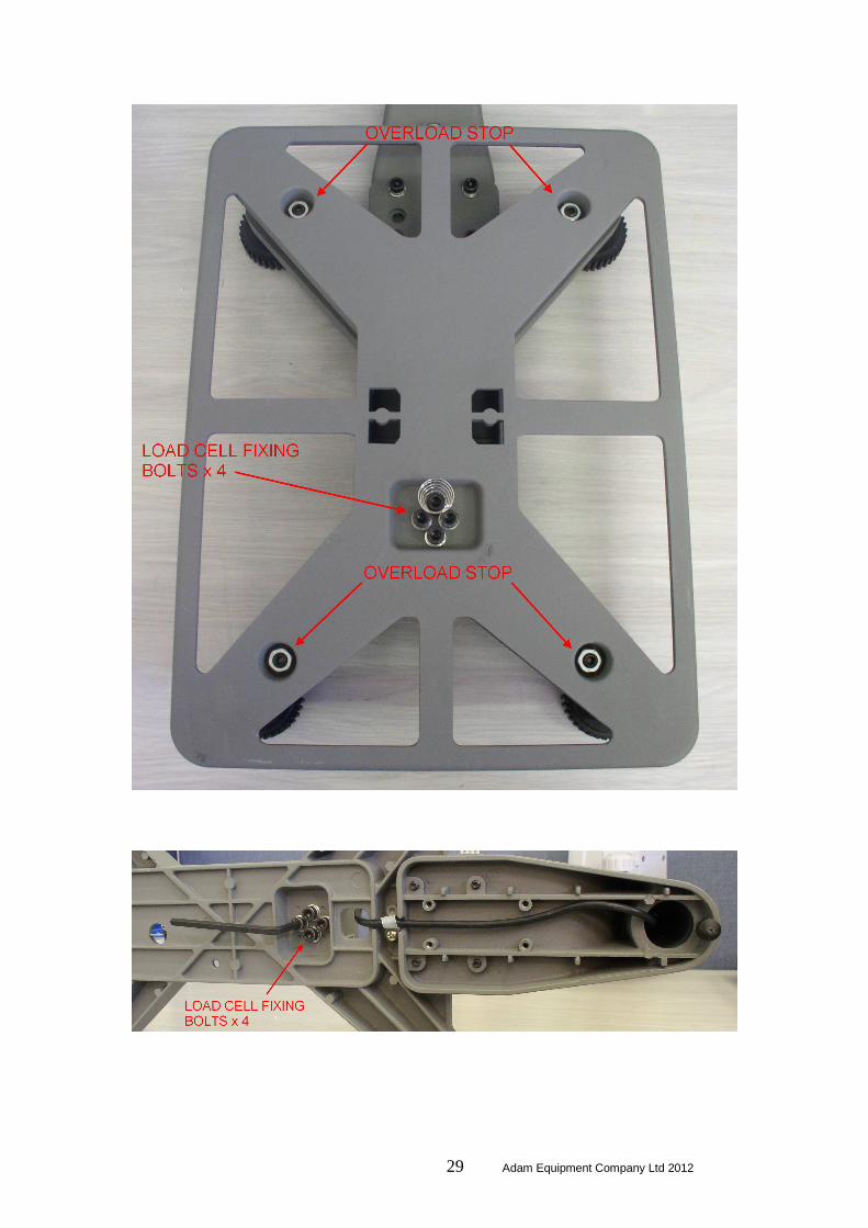
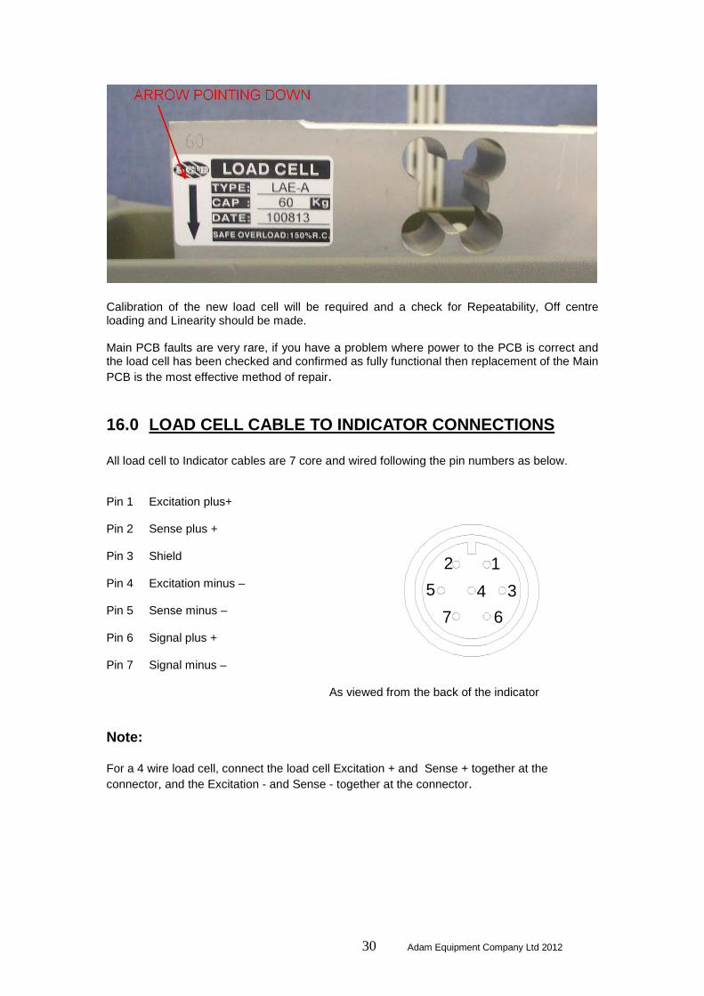
When replacing a load cell the correct type and capacity load cell should be selected, once fitted it will need to be calibrated and checked, there are 4 x overload stops that should be adjusted to protect the load cell. The overload stops should be adjusted to allow the minimum downward movement of the load cell once full load is on the top pan, adjust the overload stops individually by placing full load onto the top pan towards the area of each stop, adjust the stop screws before locking them into position using a thread locking fluid as opposed to glue. To replace a load cell firstly remove the 4 x fixing bolts that secure the upper cross/frame to the load cell, and then the 4 x fixing bolts that secure the lower cross/frame to the load cell, de solder the wires from the Indicator connector and remove the cell. Fit the new load cell to the lower cross/frame ensuring that the arrow for direction of movement points downwards as the picture below shows, tighten well and then solder the wires to the Indicator connector. Refit the upper cross/frame, tighten and check that the overload stops are correctly set before testing, Follow the steps below to remove and replace a load cell.
14.0 LOAD CELL CHECK
15.0 LOAD CELL REMOVAL AND REPLACEMENT
29 Adam Equipment Company Ltd 2012
30 Adam Equipment Company Ltd 2012
Calibration of the new load cell will be required and a check for Repeatability, Off centre loading and Linearity should be made. Main PCB faults are very rare, if you have a problem where power to the PCB is correct and the load cell has been checked and confirmed as fully functional then replacement of the Main PCB is the most effective method of repair.
All load cell to Indicator cables are 7 core and wired following the pin numbers as below. Pin 1 Excitation plus+ Pin 2 Sense plus + Pin 3 Shield Pin 4 Excitation minus – Pin 5 Sense minus – Pin 6 Signal plus + Pin 7 Signal minus –
As viewed from the back of the indicator Note: For a 4 wire load cell, connect the load cell Excitation + and Sense + together at the connector, and the Excitation - and Sense - together at the connector.
16.0 LOAD CELL CABLE TO INDICATOR CONNECTIONS
3
12
5
7 6
4
31 Adam Equipment Company Ltd 2012
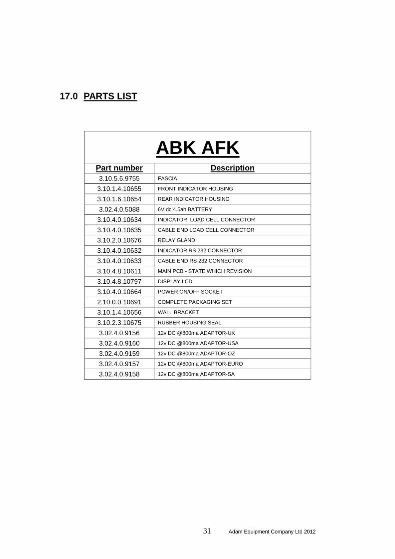
ABK AFK Part number Description 3.10.5.6.9755 FASCIA
3.10.1.4.10655 FRONT INDICATOR HOUSING
3.10.1.6.10654 REAR INDICATOR HOUSING
3.02.4.0.5088 6V dc 4.5ah BATTERY
3.10.4.0.10634 INDICATOR LOAD CELL CONNECTOR
3.10.4.0.10635 CABLE END LOAD CELL CONNECTOR
3.10.2.0.10676 RELAY GLAND
3.10.4.0.10632 INDICATOR RS 232 CONNECTOR
3.10.4.0.10633 CABLE END RS 232 CONNECTOR
3.10.4.8.10611 MAIN PCB - STATE WHICH REVISION
3.10.4.8.10797 DISPLAY LCD
3.10.4.0.10664 POWER ON/OFF SOCKET
2.10.0.0.10691 COMPLETE PACKAGING SET
3.10.1.4.10656 WALL BRACKET
3.10.2.3.10675 RUBBER HOUSING SEAL
3.02.4.0.9156 12v DC @800ma ADAPTOR-UK
3.02.4.0.9160 12v DC @800ma ADAPTOR-USA
3.02.4.0.9159 12v DC @800ma ADAPTOR-OZ
3.02.4.0.9157 12v DC @800ma ADAPTOR-EURO
3.02.4.0.9158 12v DC @800ma ADAPTOR-SA
17.0 PARTS LIST
32 Adam Equipment Company Ltd 2012
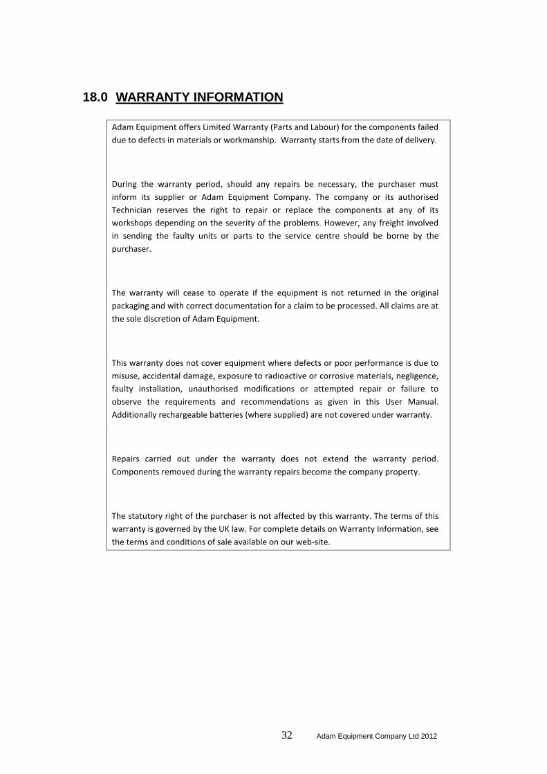
Adam Equipment offers Limited Warranty (Parts and Labour) for the components failed
due to defects in materials or workmanship. Warranty starts from the date of delivery.
During the warranty period, should any repairs be necessary, the purchaser must
inform its supplier or Adam Equipment Company. The company or its authorised
Technician reserves the right to repair or replace the components at any of its
workshops depending on the severity of the problems. However, any freight involved
in sending the faulty units or parts to the service centre should be borne by the
purchaser.
The warranty will cease to operate if the equipment is not returned in the original
packaging and with correct documentation for a claim to be processed. All claims are at
the sole discretion of Adam Equipment.
This warranty does not cover equipment where defects or poor performance is due to
misuse, accidental damage, exposure to radioactive or corrosive materials, negligence,
faulty installation, unauthorised modifications or attempted repair or failure to
observe the requirements and recommendations as given in this User Manual.
Additionally rechargeable batteries (where supplied) are not covered under warranty.
Repairs carried out under the warranty does not extend the warranty period.
Components removed during the warranty repairs become the company property.
The statutory right of the purchaser is not affected by this warranty. The terms of this
warranty is governed by the UK law. For complete details on Warranty Information, see
the terms and conditions of sale available on our web-site.
18.0 WARRANTY INFORMATION

Adam Equipment Company Ltd 2012
Manufacturer’s Declaration of Conformity
This product has been manufactured in accordance with the harmonised European standards, following the provisions of the below stated directives:
Electro Magnetic Compatibility Directive 2004/108/EC
Low Voltage Directive 2006/95/EC
Adam Equipment Co. Ltd.
Bond Avenue, Denbigh East Milton Keynes, MK1 1SW
United Kingdom
FCC COMPLIANCE
This equipment has been tested and found to comply with the limits for a Class A digital device, pursuant to Part 15 of the FCC Rules. These limits are designed to provide reasonable protection against harmful interference when the equipment is operated in a commercial environment. The equipment generates, uses, and can radiate radio frequency energy and, if not installed and used in accordance with the instruction manual, may cause harmful interference to radio communications. Operation of this equipment in a residential area is likely to cause harmful interference in which case the user will be required to correct the interference at his own expense.
Shielded interconnect cables must be employed with this equipment to insure compliance with the pertinent RF emission limits governing this device.
Changes or modifications not expressly approved by Adam Equipment could void the user's authority to operate the equipment.
WEEE COMPLIANCE
Any Electrical or Electronic Equipment (EEE) component or assembly of parts intended to be incorporated into EEE devices as defined by European Directive 2002/95/EEC must be recycled or disposed using techniques that do not introduce hazardous substances harmful to our health or the environment as listed in Directive 2002/95/EC or amending legislation. Battery disposal in Landfill Sites is more regulated since July 2002 by regulation 9 of the Landfill (England and Wales) Regulations 2002 and Hazardous Waste Regulations 2005. Battery recycling has become topical and the Waste Electrical and Electronic Equipment (WEEE) Regulations are set to impose targets for recycling.

Adam Equipment Company Ltd 2012
ADAM EQUIPMENT is an ISO 9001:2008 certified global company with more than 35 years experience in the production and sale of electronic weighing equipment. Adam products are predominantly designed for the Laboratory, Educational, Health and Fitness, retail and Industrial Segments. The product range can be described as follows:
-Analytical and Precision Balances -Compact and Portable Balances -High Capacity Balances -Moisture analysers / balances -Mechanical Scales -Counting Scales -Digital Weighing/Check-weighing Scales -High performance Platform Scales -Crane scales -Health and Fitness Scales -Retail Scales for Price computing
For a complete listing of all Adam products visit our website at
www.adamequipment.com
© Copyright by Adam Equipment Co. Ltd. All rights reserved. No part of this publication may be reprinted or
translated in any form or by any means without the prior permission of Adam Equipment.
Adam Equipment reserves the right to make changes to the technology, features, specifications and design of
the equipment without notice.
All information contained within this publication is to the best of our knowledge timely, complete and accurate
when issued. However, we are not responsible for misinterpretations which may result from the reading of
this material.
The latest version of this publication can be found on our Website.
www.adamequipment.com