Embed Size (px)
Citation preview
Abstract – Electromagnetic Interference/Compatibility (EMI/EMC) Control Test and Measurement Facility
Test process, milestones and inputs are unknowns to first-time users of the EMI/EMC Test Facility. The User Test Planning Guide aids in establishing expectations for both NASA and non-NASA facility customers. The potential audience for this guide includes both internal and commercial spaceflight hardware/software developers. It is intended to assist their test engineering personnel in test planning and execution. Material covered includes a roadmap of the test process, roles and responsibilities of facility and user, major milestones, facility capabilities, and inputs required by the facility. Samples of deliverables, test article interfaces, and inputs necessary to define test scope, cost, and schedule are included as an appendix to the guide.
https://ntrs.nasa.gov/search.jsp?R=20110016138 2018-06-01T14:30:30+00:00Z
JSC-XXXXX
Electromagnetic Interference/Compatibility (EMI/EMC) Control Test and Measurement Facility
User Test Planning Guide
National Aeronautics and Space Administration Lyndon B. Johnson Space Center Houston, Texas 77058
JSC-XXXXX
2
Table of Contents
1.0 Electromagnetic Interference/Compatibility Test Facility .............................................3
2.0 Facility Layout ...................................................................................................................4
3.0 Safety and Health ..............................................................................................................6
4.0 Test Process Flow ............................................................................................................6
4.1. Proprietary Information ....................................................................................................7
4.2 Test Initiation Phase ........................................................................................................8
4.2.1 Test Request ...................................................................................................................... 8
4.2.2 Schedule and Cost Estimate ............................................................................................... 9
4.3 Test Preparation Phase ...................................................................................................9
4.3.1 Test Requirements ........................................................................................................... 10
4.3.2 Test Article Documentation ............................................................................................... 10
4.3.3 Test Plan .......................................................................................................................... 11
4.3.4 Test Schedule ................................................................................................................... 11
4.3.5 Test Article Delivery .......................................................................................................... 11
4.3.6 Test Readiness Review .................................................................................................... 11
4.4 Test Execution Phase .................................................................................................... 12
4.4.1 Test Authority ................................................................................................................... 12
4.4.2 Test Deviations ................................................................................................................. 12
4.5 Test Closeout Phase ..................................................................................................... 13
4.5.1 Customer Feedback ......................................................................................................... 13
5.0 Facility Access ................................................................................................................ 14
6.0 Roles and Responsibilities ............................................................................................ 15
Acronyms .................................................................................................................................. 17
Appendices ............................................................................................................................... 18
Appendix A Facility Interfaces .............................................................................................. 19
Appendix B Test Request Worksheet .................................................................................. 23
Appendix C Facility Specifications ....................................................................................... 28
Appendix D Facility Equipment ............................................................................................ 29
Appendix E Sample Test Configurations ............................................................................. 32
JSC-XXXXX
3
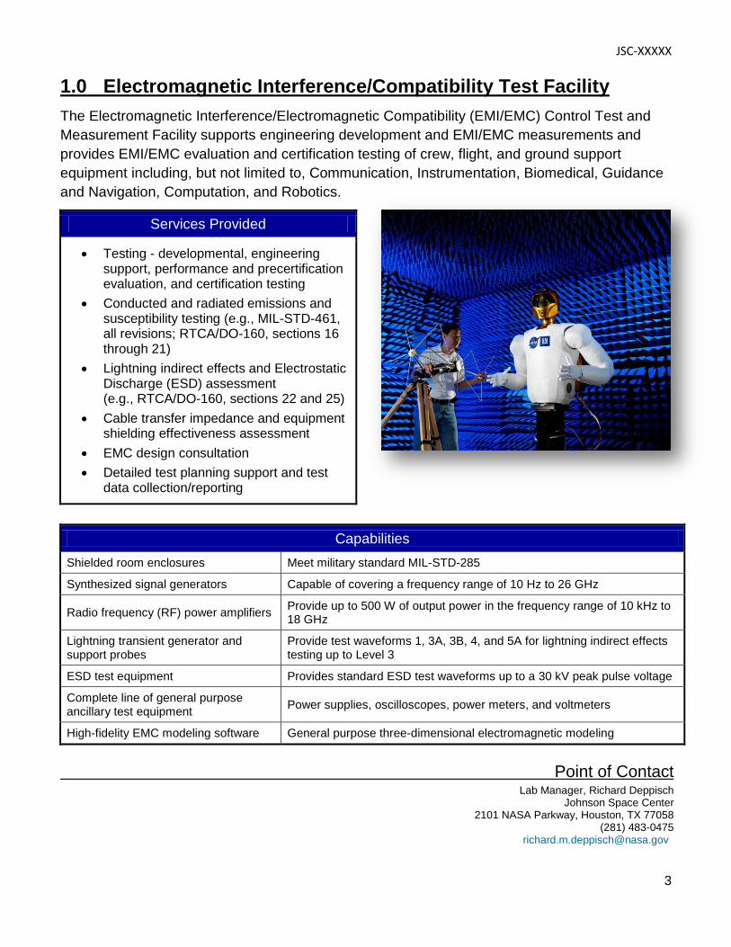
1.0 Electromagnetic Interference/Compatibility Test Facility The Electromagnetic Interference/Electromagnetic Compatibility (EMI/EMC) Control Test and Measurement Facility supports engineering development and EMI/EMC measurements and provides EMI/EMC evaluation and certification testing of crew, flight, and ground support equipment including, but not limited to, Communication, Instrumentation, Biomedical, Guidance and Navigation, Computation, and Robotics.
Services Provided
• Testing - developmental, engineering support, performance and precertification evaluation, and certification testing
• Conducted and radiated emissions and susceptibility testing (e.g., MIL-STD-461, all revisions; RTCA/DO-160, sections 16 through 21)
• Lightning indirect effects and Electrostatic Discharge (ESD) assessment (e.g., RTCA/DO-160, sections 22 and 25)
• Cable transfer impedance and equipment shielding effectiveness assessment
• EMC design consultation • Detailed test planning support and test
data collection/reporting
Capabilities Shielded room enclosures Meet military standard MIL-STD-285
Synthesized signal generators Capable of covering a frequency range of 10 Hz to 26 GHz
Radio frequency (RF) power amplifiers Provide up to 500 W of output power in the frequency range of 10 kHz to 18 GHz
Lightning transient generator and support probes
Provide test waveforms 1, 3A, 3B, 4, and 5A for lightning indirect effects testing up to Level 3
ESD test equipment Provides standard ESD test waveforms up to a 30 kV peak pulse voltage
Complete line of general purpose ancillary test equipment Power supplies, oscilloscopes, power meters, and voltmeters
High-fidelity EMC modeling software General purpose three-dimensional electromagnetic modeling
Point of Contact
Lab Manager, Richard Deppisch Johnson Space Center 2101 NASA Parkway, Houston, TX 77058 (281) 483-0475 [email protected]
JSC-XXXXX
4
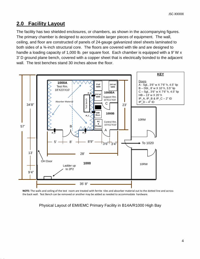
2.0 Facility Layout The facility has two shielded enclosures, or chambers, as shown in the accompanying figures. The primary chamber is designed to accommodate larger pieces of equipment. The wall, ceiling, and floor are constructed of panels of 24-gauge galvanized steel sheets laminated to both sides of a ¾-inch structural core. The floors are covered with tile and are designed to handle a loading capacity of 1,000 lb. per square foot. Each chamber is equipped with a 9′ W x 3′ D ground plane bench, covered with a copper sheet that is electrically bonded to the adjacent wall. The test benches stand 30 inches above the floor.
KEY
DoorsA - Sgl., 3’6” w X 7’6” h, 4.5” lipB – Dbl., 8’ w X 10’ h, 3.5” lipC – Sgl., 3’6” w X 7’6” h, 4.5” lipHB – 13’ w X 20’ hIP_A, IP_B & IP_C – 2” IDIP_D – 4” ID
35’ 8”
1000ATest Rm.
18’X23’X10’
1000OH Door
Control Rm.10’X12’X10’
Support Rm.10’X11’X10’
Ladder up to 2P2
To 1020
10RM
10RW
BA
C
3’x5’table
2’6”x5’table
EMI Rcvr.
PC&
Printer
1000B
5’ 8’ 8’9”
13’
1000BA
2’6”x5’table
57’
23’
28’
3’6” 3’4”
9’4”
34’8”
IP_A IP_B
IP_C
IP_D
NOTE: The walls and ceiling of the test room are treated with ferrite tiles and absorber material out to the dotted line and across the back wall. Test Bench can be removed or another may be added as needed to accommodate hardware.
Test
ben
ch
Absorber Material
Physical Layout of EMI/EMC Primary Facility in B14A/R1000 High Bay
JSC-XXXXX
5
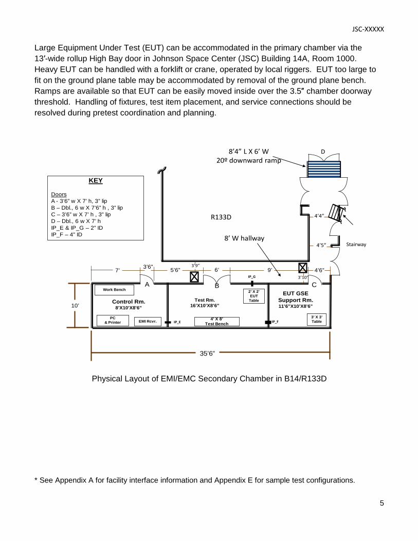
Large Equipment Under Test (EUT) can be accommodated in the primary chamber via the 13′-wide rollup High Bay door in Johnson Space Center (JSC) Building 14A, Room 1000. Heavy EUT can be handled with a forklift or crane, operated by local riggers. EUT too large to fit on the ground plane table may be accommodated by removal of the ground plane bench. Ramps are available so that EUT can be easily moved inside over the 3.5″ chamber doorway threshold. Handling of fixtures, test item placement, and service connections should be resolved during pretest coordination and planning.
KEY
DoorsA - 3’6” w X 7’ h, 3” lipB – Dbl., 6 w X 7’6” h , 3” lipC – 3’6” w X 7’ h , 3” lipD – Dbl., 6 w X 7’ hIP_E & IP_G – 2” IDIP_F – 4” ID
Stairway
Test Rm.16’X10’X8’6”
A B C2’ X 2’EUT
Table
3’ X 3’TableEMI Rcvr.
PC& Printer
Work Bench
Control Rm.8’X10’X8’6”
EUT GSESupport Rm.11’6”X10’X8’6”
4’ X 8’Test Bench
10’
3’6” 6’ 4’6”9’5’6”7’
35’6”
R133D
8’4” L X 6’ W20º downward ramp
8’ W hallway
D
3’9”
3’10”
4’5”
4’4”
IP_G
IP_E IP_F
Physical Layout of EMI/EMC Secondary Chamber in B14/R133D
* See Appendix A for facility interface information and Appendix E for sample test configurations.
JSC-XXXXX
6
3.0 Safety and Health Safety is an integral part of the culture at the National Aeronautics and Space Administration (NASA). Management, leadership, and employee involvement from all organizations are critical to the success of NASA’s safety program. In order to ensure personal safety and a safe test environment throughout the process, the requester shall furnish the facility with the information necessary to perform a hazard assessment of the test article. Additionally, while visiting JSC, the requester shall follow all facility-specific safety and health requirements. A facility safety briefing shall be provided to all personnel prior to the start of the test. The safety briefing will include a review of the laboratory safety rules, potential hazards, and emergency procedures.
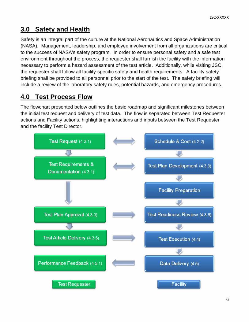
4.0 Test Process Flow The flowchart presented below outlines the basic roadmap and significant milestones between the initial test request and delivery of test data. The flow is separated between Test Requester actions and Facility actions, highlighting interactions and inputs between the Test Requester and the facility Test Director.
JSC-XXXXX
7
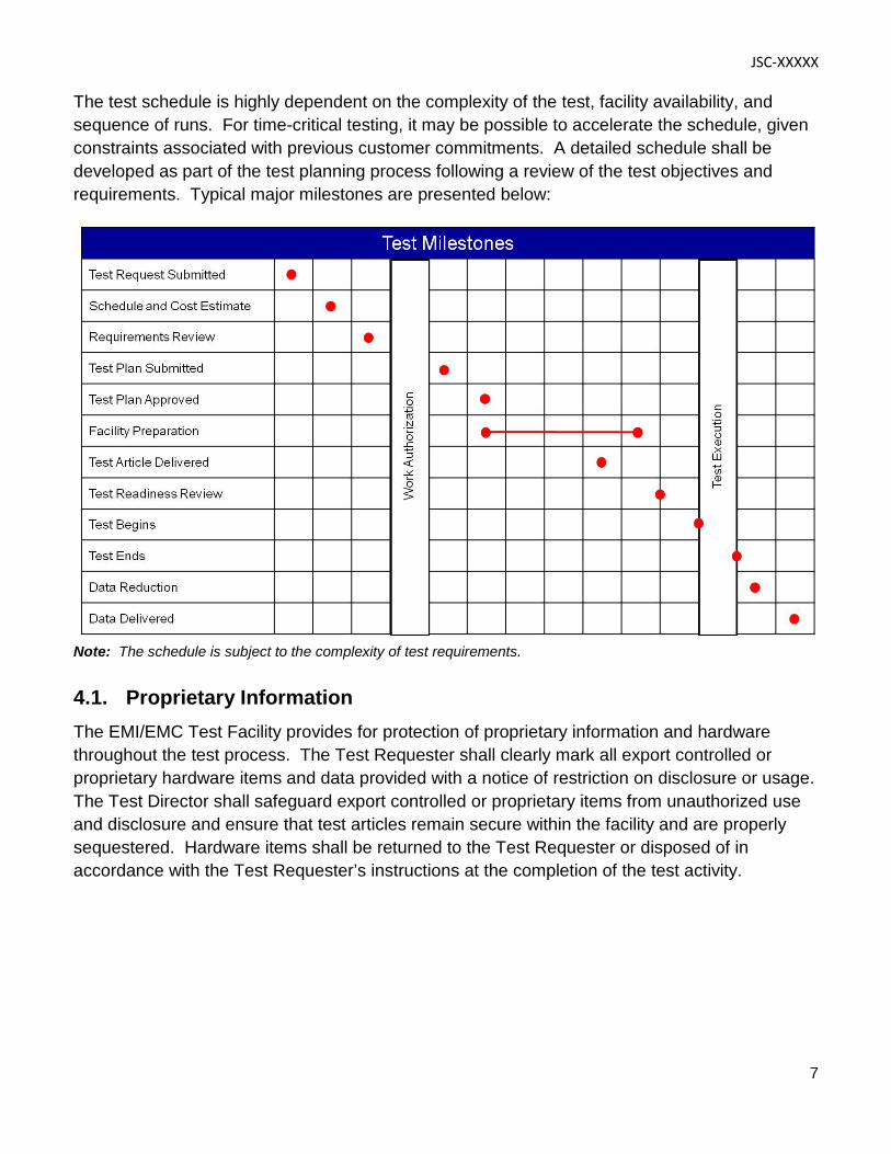
The test schedule is highly dependent on the complexity of the test, facility availability, and sequence of runs. For time-critical testing, it may be possible to accelerate the schedule, given constraints associated with previous customer commitments. A detailed schedule shall be developed as part of the test planning process following a review of the test objectives and requirements. Typical major milestones are presented below:
Note: The schedule is subject to the complexity of test requirements.
4.1. Proprietary Information The EMI/EMC Test Facility provides for protection of proprietary information and hardware throughout the test process. The Test Requester shall clearly mark all export controlled or proprietary hardware items and data provided with a notice of restriction on disclosure or usage. The Test Director shall safeguard export controlled or proprietary items from unauthorized use and disclosure and ensure that test articles remain secure within the facility and are properly sequestered. Hardware items shall be returned to the Test Requester or disposed of in accordance with the Test Requester’s instructions at the completion of the test activity.
JSC-XXXXX
8
4.2 Test Initiation Phase The test initiation phase establishes the relationship between the Test Requester and the Test Director. The Test Requester shall provide a test request to the Test Director. The test request will be used to determine test feasibility and to develop an estimated cost and a preliminary test schedule. An initial requirements review meeting may be necessary in order to discuss the characteristics of the test article, the test approach, or any special considerations for the test. An onsite tour of the facility is highly recommended for familiarization and to provide an opportunity for an exchange of technical information. Inputs: Test Requester provides test request, identifies Test Article Expert
Activities: Facility Test Director reviews test request to determine test feasibility
Outputs: Facility delivers preliminary test plan, estimated cost and schedule to Test Requester
4.2.1 Test Request
The test request outlines the EUT requirements, test objectives, test article description, and preferred schedule. A Test Request Worksheet is provided in Appendix B. This worksheet addresses the basic requirements for testing in the EMI/EMC Test Facility. It is suggested that the Test Requester complete this worksheet to facilitate the development of a preliminary test plan. At a minimum, the test request should include the following information:
Test Requirements and Objectives
A brief description of the test requirements including, but not limited to, the following:
• Applicable EMI/EMC requirements/limits/specification (e.g., customer specification, MIL-STD-461, DO-160)
• Desired test environment and modes of operation
• Proposed test approach
• Test data requirements
JSC-XXXXX
9
Test Article Description
A brief description of the test article including, but not limited to, the following:
• Size/dimensions (provide drawings, sketches, photos)
• Weight
• Test article interface (electrical, mechanical, fluids, gases, pressure, temperature, other)
• Special considerations [hazards, cleanliness, compatibility, Material Safety Data Sheets (MSDS)]
• Handling, storage, and security requirements
Schedule
Identify the desired start date and the required date for delivery of the data/test report.
4.2.2 Schedule and Cost Estimate
A preliminary cost and schedule estimate, including major milestones, will be delivered following review of the Test Request Worksheet. Additional details and refinement of the cost and schedule estimate will be worked out with the Test Requester as test planning proceeds, with a final version to be agreed upon prior to the Test Readiness Review (TRR).
4.3 Test Preparation Phase The detailed test plan and test schedule are finalized during the test preparation phase. The Test Requester shall provide detailed test requirements and test article documentation to the Test Director. A TRR will be held following approval of the test plan. Inputs: Test Requester provides test requirements and objectives, and test article
documentation
Activities: Facility and Test Requester develop test plan
Facility begins assembly of facility-unique interface/support structure(s) (if needed)
Test Requester ships/transports test article and associated support/peripheral equipment to JSC
Outputs: Test Requester approves test plan, schedule, and final cost estimate
Facility hosts TRR
JSC-XXXXX
10
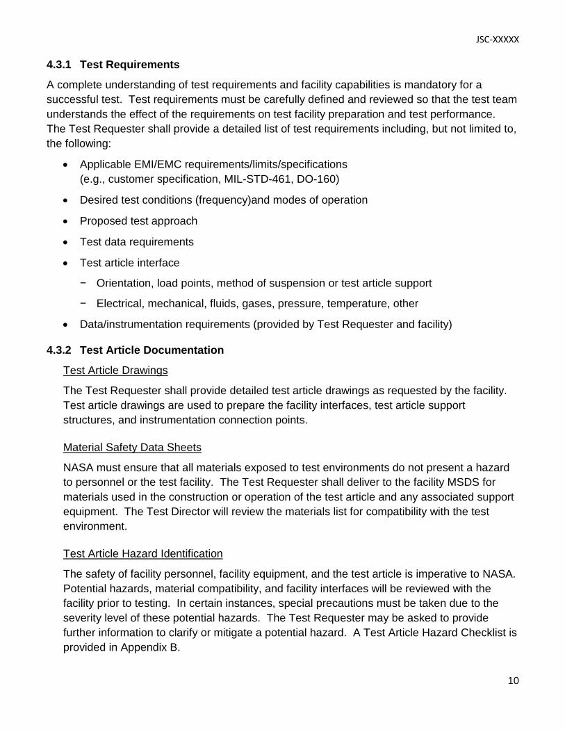
4.3.1 Test Requirements
A complete understanding of test requirements and facility capabilities is mandatory for a successful test. Test requirements must be carefully defined and reviewed so that the test team understands the effect of the requirements on test facility preparation and test performance. The Test Requester shall provide a detailed list of test requirements including, but not limited to, the following:
• Applicable EMI/EMC requirements/limits/specifications (e.g., customer specification, MIL-STD-461, DO-160)
• Desired test conditions (frequency)and modes of operation
• Proposed test approach
• Test data requirements
• Test article interface
− Orientation, load points, method of suspension or test article support
− Electrical, mechanical, fluids, gases, pressure, temperature, other
• Data/instrumentation requirements (provided by Test Requester and facility)
4.3.2 Test Article Documentation
Test Article Drawings
The Test Requester shall provide detailed test article drawings as requested by the facility. Test article drawings are used to prepare the facility interfaces, test article support structures, and instrumentation connection points. Material Safety Data Sheets
NASA must ensure that all materials exposed to test environments do not present a hazard to personnel or the test facility. The Test Requester shall deliver to the facility MSDS for materials used in the construction or operation of the test article and any associated support equipment. The Test Director will review the materials list for compatibility with the test environment. Test Article Hazard Identification
The safety of facility personnel, facility equipment, and the test article is imperative to NASA. Potential hazards, material compatibility, and facility interfaces will be reviewed with the facility prior to testing. In certain instances, special precautions must be taken due to the severity level of these potential hazards. The Test Requester may be asked to provide further information to clarify or mitigate a potential hazard. A Test Article Hazard Checklist is provided in Appendix B.
JSC-XXXXX
11
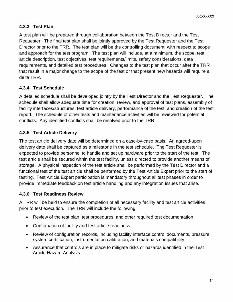
4.3.3 Test Plan
A test plan will be prepared through collaboration between the Test Director and the Test Requester. The final test plan shall be jointly approved by the Test Requester and the Test Director prior to the TRR. The test plan will be the controlling document, with respect to scope and approach for the test program. The test plan will include, at a minimum, the scope, test article description, test objectives, test requirements/limits, safety considerations, data requirements, and detailed test procedures. Changes to the test plan that occur after the TRR that result in a major change to the scope of the test or that present new hazards will require a delta TRR.
4.3.4 Test Schedule
A detailed schedule shall be developed jointly by the Test Director and the Test Requester. The schedule shall allow adequate time for creation, review, and approval of test plans, assembly of facility interfaces/structures, test article delivery, performance of the test, and creation of the test report. The schedule of other tests and maintenance activities will be reviewed for potential conflicts. Any identified conflicts shall be resolved prior to the TRR.
4.3.5 Test Article Delivery
The test article delivery date will be determined on a case-by-case basis. An agreed-upon delivery date shall be captured as a milestone in the test schedule. The Test Requester is expected to provide personnel to handle and set up hardware prior to the start of the test. The test article shall be secured within the test facility, unless directed to provide another means of storage. A physical inspection of the test article shall be performed by the Test Director and a functional test of the test article shall be performed by the Test Article Expert prior to the start of testing. Test Article Expert participation is mandatory throughout all test phases in order to provide immediate feedback on test article handling and any integration issues that arise.
4.3.6 Test Readiness Review
A TRR will be held to ensure the completion of all necessary facility and test article activities prior to test execution. The TRR will include the following:
• Review of the test plan, test procedures, and other required test documentation • Confirmation of facility and test article readiness
• Review of configuration records, including facility interface control documents, pressure system certification, instrumentation calibration, and materials compatibility
• Assurance that controls are in place to mitigate risks or hazards identified in the Test Article Hazard Analysis
JSC-XXXXX
12
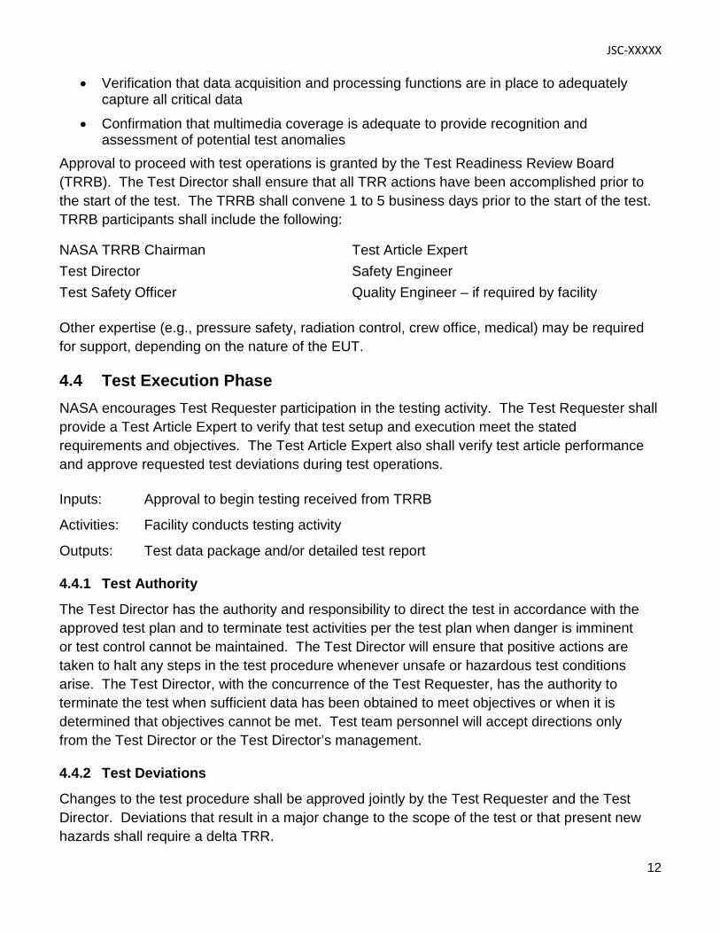
• Verification that data acquisition and processing functions are in place to adequately capture all critical data
• Confirmation that multimedia coverage is adequate to provide recognition and assessment of potential test anomalies
Approval to proceed with test operations is granted by the Test Readiness Review Board (TRRB). The Test Director shall ensure that all TRR actions have been accomplished prior to the start of the test. The TRRB shall convene 1 to 5 business days prior to the start of the test. TRRB participants shall include the following:
NASA TRRB Chairman Test Article Expert Test Director Safety Engineer Test Safety Officer Quality Engineer – if required by facility
Other expertise (e.g., pressure safety, radiation control, crew office, medical) may be required for support, depending on the nature of the EUT.
4.4 Test Execution Phase NASA encourages Test Requester participation in the testing activity. The Test Requester shall provide a Test Article Expert to verify that test setup and execution meet the stated requirements and objectives. The Test Article Expert also shall verify test article performance and approve requested test deviations during test operations. Inputs: Approval to begin testing received from TRRB
Activities: Facility conducts testing activity
Outputs: Test data package and/or detailed test report
4.4.1 Test Authority
The Test Director has the authority and responsibility to direct the test in accordance with the approved test plan and to terminate test activities per the test plan when danger is imminent or test control cannot be maintained. The Test Director will ensure that positive actions are taken to halt any steps in the test procedure whenever unsafe or hazardous test conditions arise. The Test Director, with the concurrence of the Test Requester, has the authority to terminate the test when sufficient data has been obtained to meet objectives or when it is determined that objectives cannot be met. Test team personnel will accept directions only from the Test Director or the Test Director’s management.
4.4.2 Test Deviations
Changes to the test procedure shall be approved jointly by the Test Requester and the Test Director. Deviations that result in a major change to the scope of the test or that present new hazards shall require a delta TRR.
JSC-XXXXX
13
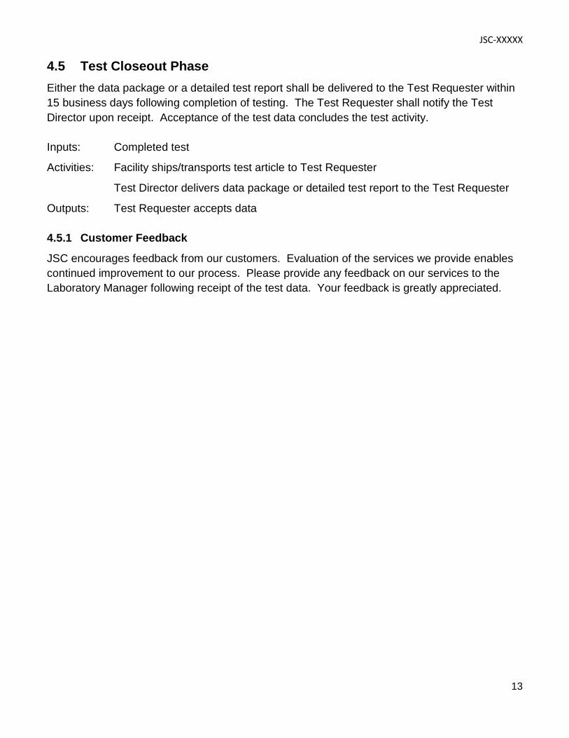
4.5 Test Closeout Phase Either the data package or a detailed test report shall be delivered to the Test Requester within 15 business days following completion of testing. The Test Requester shall notify the Test Director upon receipt. Acceptance of the test data concludes the test activity. Inputs: Completed test
Activities: Facility ships/transports test article to Test Requester
Test Director delivers data package or detailed test report to the Test Requester
Outputs: Test Requester accepts data
4.5.1 Customer Feedback
JSC encourages feedback from our customers. Evaluation of the services we provide enables continued improvement to our process. Please provide any feedback on our services to the Laboratory Manager following receipt of the test data. Your feedback is greatly appreciated.
JSC-XXXXX
14
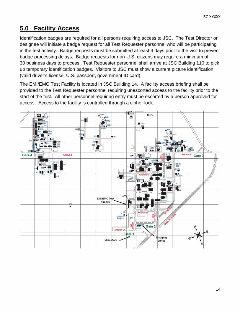
5.0 Facility Access Identification badges are required for all persons requiring access to JSC. The Test Director or designee will initiate a badge request for all Test Requester personnel who will be participating in the test activity. Badge requests must be submitted at least 4 days prior to the visit to prevent badge processing delays. Badge requests for non-U.S. citizens may require a minimum of 30 business days to process. Test Requester personnel shall arrive at JSC Building 110 to pick up temporary identification badges. Visitors to JSC must show a current picture identification (valid driver’s license, U.S. passport, government ID card). The EMI/EMC Test Facility is located in JSC Building 14. A facility access briefing shall be provided to the Test Requester personnel requiring unescorted access to the facility prior to the start of the test. All other personnel requiring entry must be escorted by a person approved for access. Access to the facility is controlled through a cipher lock.
JSC-XXXXX
15
6.0 Roles and Responsibilities
Lab Manager – Responsible for operations of the facility. The Lab Manager is the initial point of contact for the Test Requester. Test Director – Has overall responsibility for all phases of the test process. Test Requester – The client requesting performance of a test activity. The Test Requester is responsible for the test article and for providing a Test Article Expert. Test Article Expert – A representative of the Test Requester with thorough knowledge of the test article and how it is to be operated in the test environment. The Test Article Expert also is responsible for approving the test plan and verifying that test objectives are met. Test Conductor – Assigned under the authority of the Test Director to execute the test in accordance with the approved test plan. Test Safety Officer – Monitors and approves all hazardous operations for the test. The Test Safety Officer has the authority to recommend the discontinuance of test operations considered unsafe. Safety Engineer – Reviews the Test Article Hazard Checklist and generates the integrated hazard analysis for the test facility to identify any additional hazards that could result in injury to personnel. Facility Quality Engineer – Responsible for verifying that the test facility is ready for the test by ensuring that all constraints to the test have been closed.
JSC-XXXXX
16
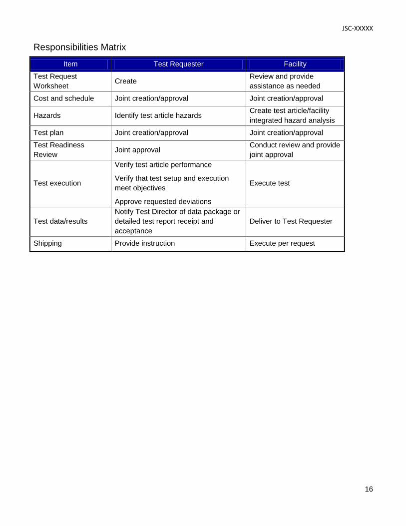
Responsibilities Matrix
Item Test Requester Facility
Test Request Worksheet Create Review and provide
assistance as needed
Cost and schedule Joint creation/approval Joint creation/approval
Hazards Identify test article hazards Create test article/facility integrated hazard analysis
Test plan Joint creation/approval Joint creation/approval
Test Readiness Review Joint approval Conduct review and provide
joint approval
Test execution
Verify test article performance
Verify that test setup and execution meet objectives
Approve requested deviations
Execute test
Test data/results Notify Test Director of data package or detailed test report receipt and acceptance
Deliver to Test Requester
Shipping Provide instruction Execute per request
JSC-XXXXX
17
Acronyms
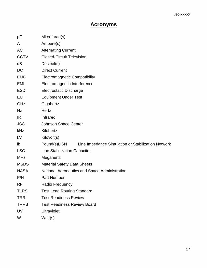
µF Microfarad(s) A Ampere(s) AC Alternating Current CCTV Closed-Circuit Television dB Decibel(s) DC Direct Current EMC Electromagnetic Compatibility EMI Electromagnetic Interference ESD Electrostatic Discharge EUT Equipment Under Test GHz Gigahertz Hz Hertz IR Infrared JSC Johnson Space Center kHz Kilohertz kV Kilovolt(s) lb Pound(s)LISN Line Impedance Simulation or Stabilization Network LSC Line Stabilization Capacitor MHz Megahertz MSDS Material Safety Data Sheets NASA National Aeronautics and Space Administration P/N Part Number RF Radio Frequency TLRS Test Lead Routing Standard TRR Test Readiness Review TRRB Test Readiness Review Board UV Ultraviolet W Watt(s)
JSC-XXXXX
18
Appendices A. Facility Interfaces B. Test Request Worksheet C. Facility Specifications D. Facility Equipment E. Sample Test Configurations
JSC-XXXXX
19
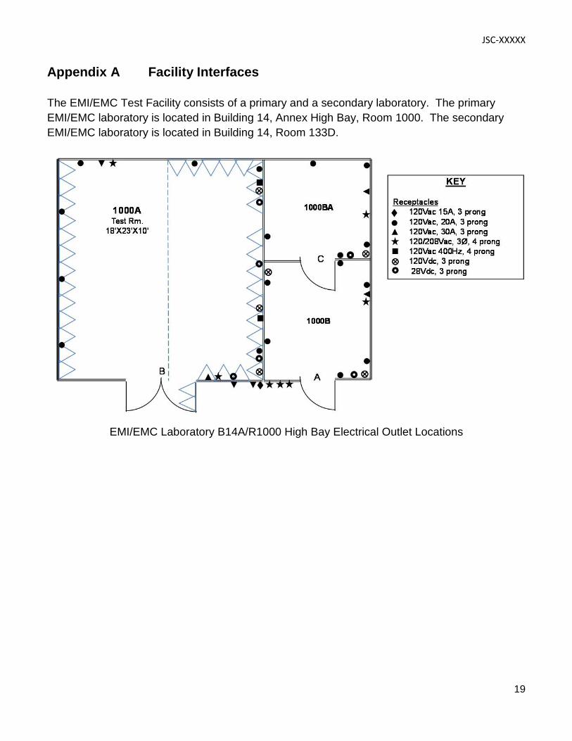
Appendix A Facility Interfaces
The EMI/EMC Test Facility consists of a primary and a secondary laboratory. The primary EMI/EMC laboratory is located in Building 14, Annex High Bay, Room 1000. The secondary EMI/EMC laboratory is located in Building 14, Room 133D.
EMI/EMC Laboratory B14A/R1000 High Bay Electrical Outlet Locations
JSC-XXXXX
20
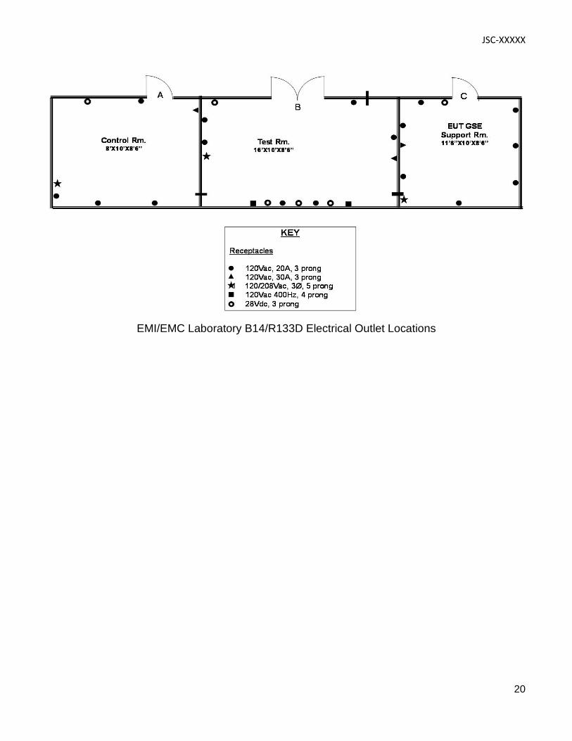
EMI/EMC Laboratory B14/R133D Electrical Outlet Locations
Example test article in a wedge
JSC-XXXXX
21
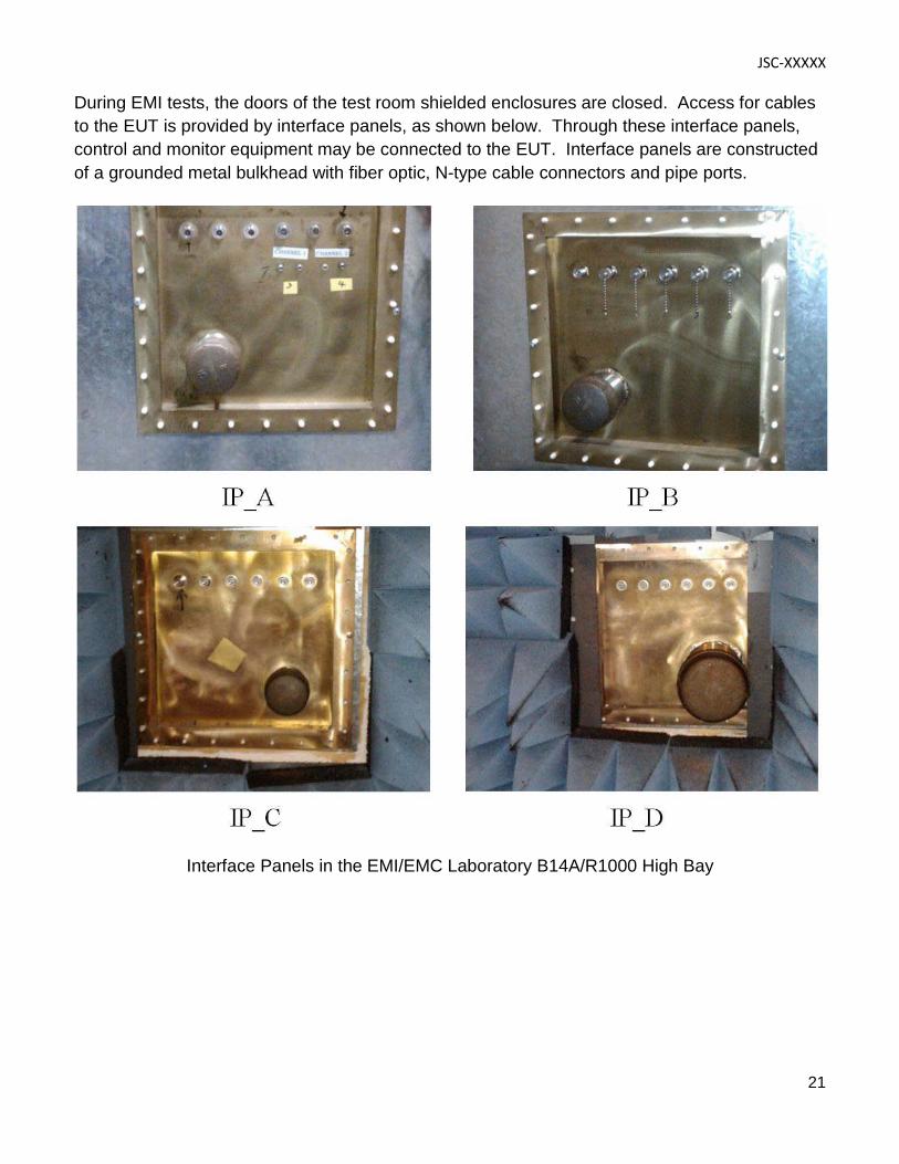
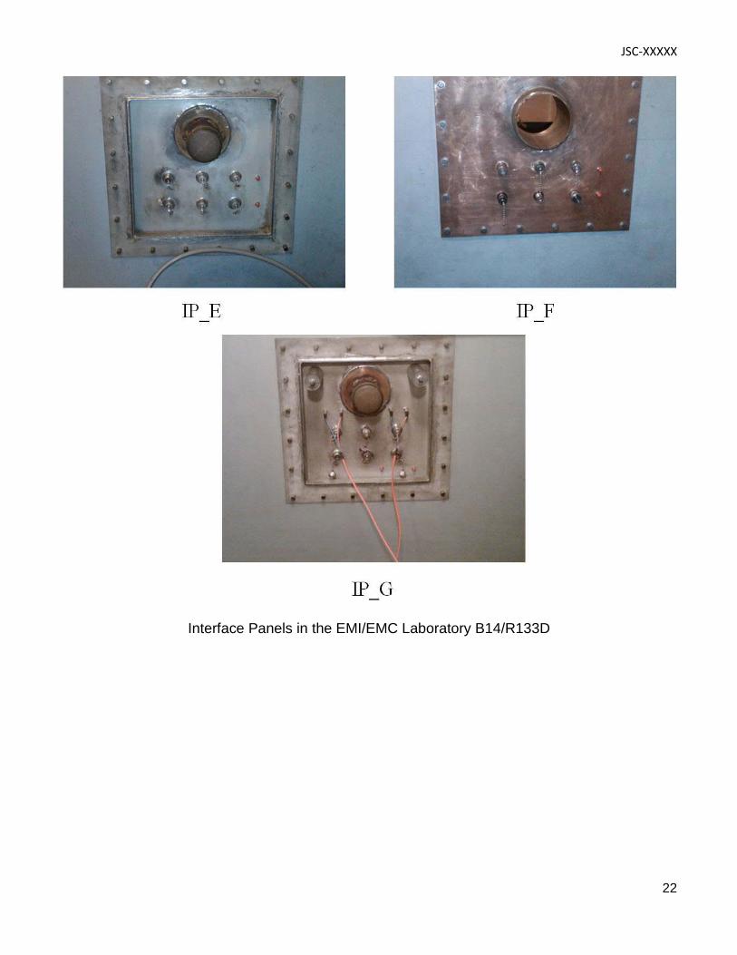
During EMI tests, the doors of the test room shielded enclosures are closed. Access for cables to the EUT is provided by interface panels, as shown below. Through these interface panels, control and monitor equipment may be connected to the EUT. Interface panels are constructed of a grounded metal bulkhead with fiber optic, N-type cable connectors and pipe ports.
Interface Panels in the EMI/EMC Laboratory B14A/R1000 High Bay
JSC-XXXXX
22
Interface Panels in the EMI/EMC Laboratory B14/R133D
JSC-XXXXX
23
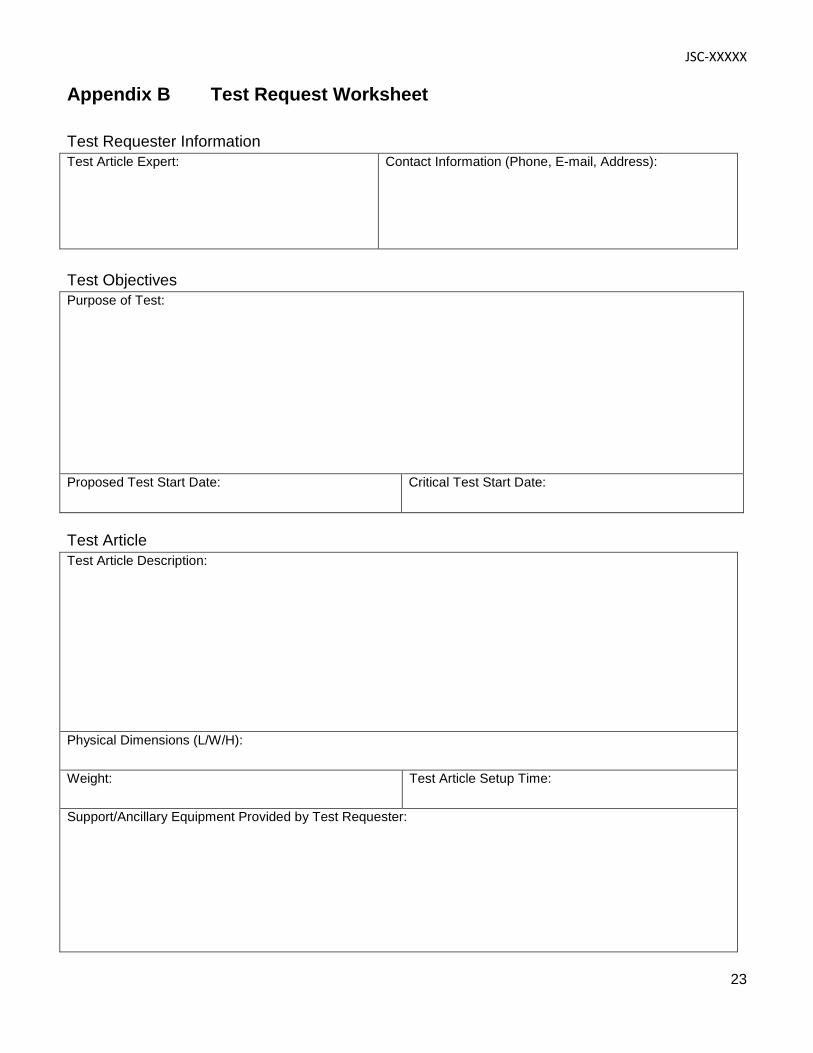
Appendix B Test Request Worksheet
Test Requester Information Test Article Expert:
Contact Information (Phone, E-mail, Address):
Test Objectives Purpose of Test:
Proposed Test Start Date:
Critical Test Start Date:
Test Article Test Article Description:
Physical Dimensions (L/W/H): Weight:
Test Article Setup Time:
Support/Ancillary Equipment Provided by Test Requester:
EQUPMENT LOCK LID
JSC-XXXXX
24
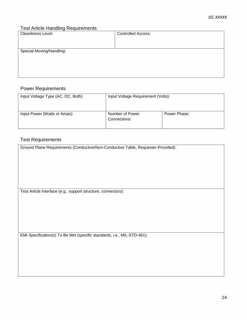
Test Article Handling Requirements Cleanliness Level:
Controlled Access:
Special Moving/Handling:
Power Requirements Input Voltage Type (AC, DC, Both):
Input Voltage Requirement (Volts):
Input Power (Watts or Amps):
Number of Power Connections:
Power Phase:
Test Requirements Ground Plane Requirements (Conductive/Non-Conductive Table, Requester-Provided):
Test Article Interface (e.g., support structure, connectors):
EMI Specification(s) To Be Met (specific standards, i.e., MIL-STD-461):
JSC-XXXXX
25
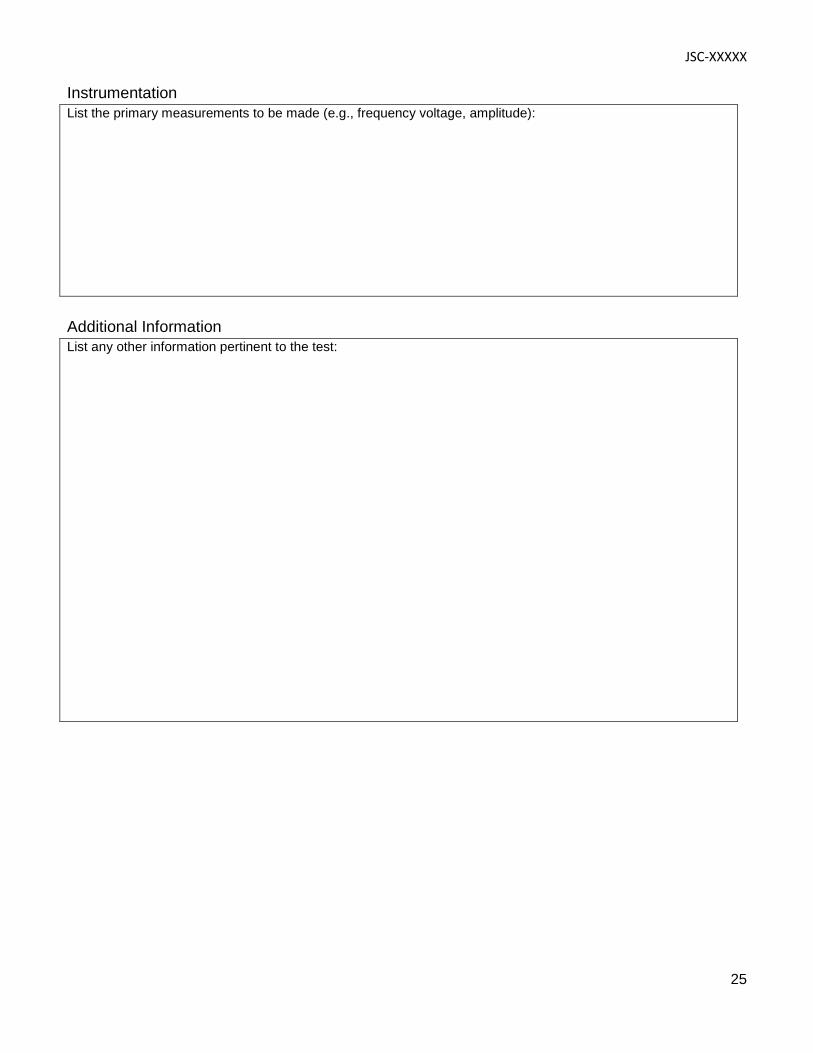
Instrumentation List the primary measurements to be made (e.g., frequency voltage, amplitude):
Additional Information List any other information pertinent to the test:
JSC-XXXXX
26
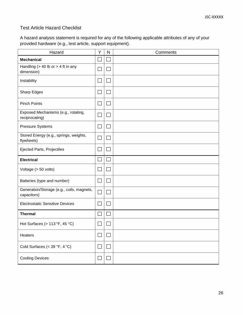
Test Article Hazard Checklist
A hazard analysis statement is required for any of the following applicable attributes of any of your provided hardware (e.g., test article, support equipment).
Hazard Y N Comments Mechanical
Handling (> 40 lb or > 4 ft in any dimension)
Instability
Sharp Edges
Pinch Points
Exposed Mechanisms (e.g., rotating, reciprocating)
Pressure Systems
Stored Energy (e.g., springs, weights, flywheels)
Ejected Parts, Projectiles
Electrical
Voltage (> 50 volts)
Batteries (type and number)
Generation/Storage (e.g., coils, magnets, capacitors)
Electrostatic Sensitive Devices
Thermal
Hot Surfaces (> 113 °F, 45 °C)
Heaters
Cold Surfaces (< 39 °F, 4 °C)
Cooling Devices
JSC-XXXXX
27
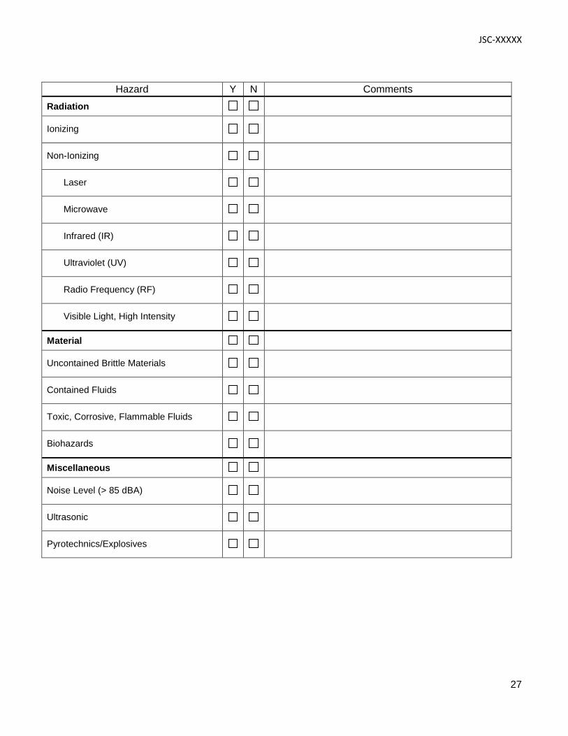
Hazard Y N Comments Radiation
Ionizing
Non-Ionizing
Laser
Microwave
Infrared (IR)
Ultraviolet (UV)
Radio Frequency (RF)
Visible Light, High Intensity
Material
Uncontained Brittle Materials
Contained Fluids
Toxic, Corrosive, Flammable Fluids
Biohazards
Miscellaneous
Noise Level (> 85 dBA)
Ultrasonic
Pyrotechnics/Explosives
JSC-XXXXX
28
Appendix C Facility Specifications
Specifications Measurement Bandwidths
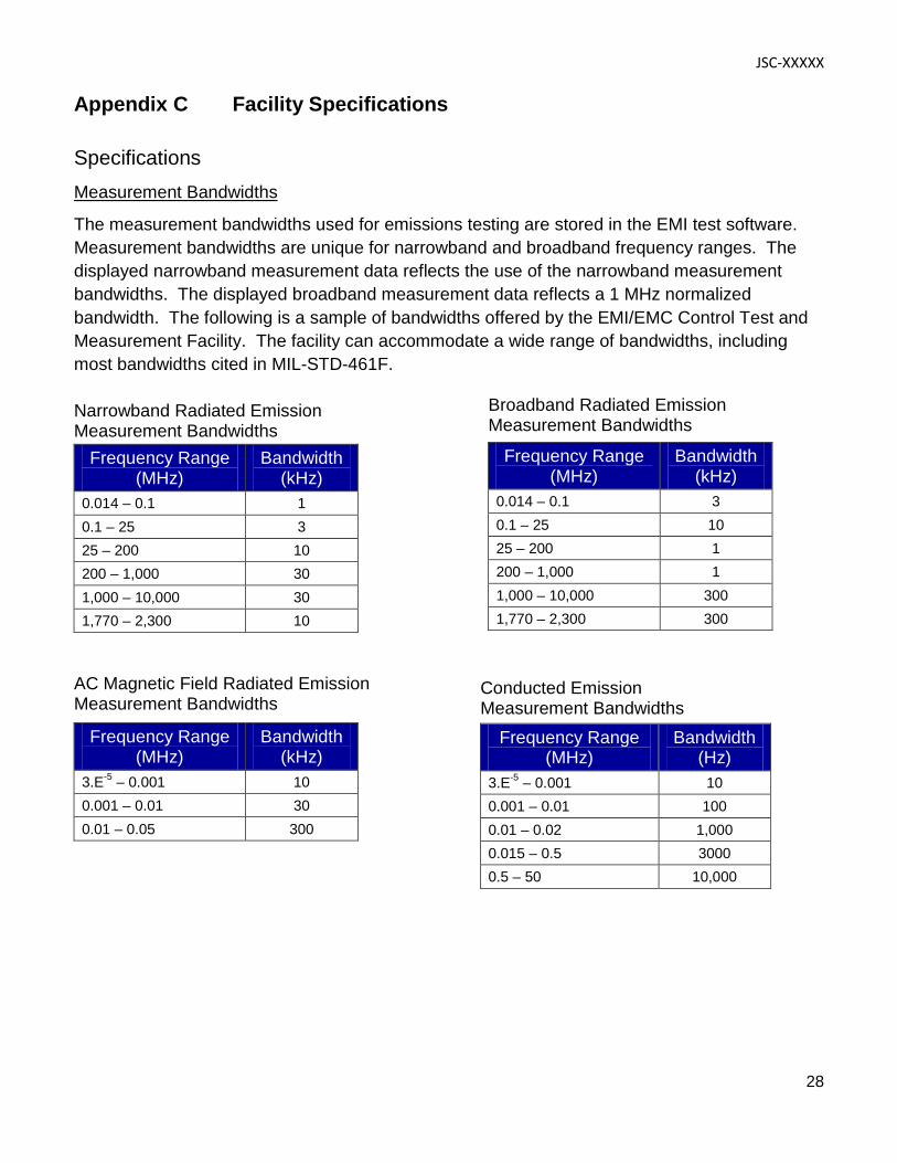
The measurement bandwidths used for emissions testing are stored in the EMI test software. Measurement bandwidths are unique for narrowband and broadband frequency ranges. The displayed narrowband measurement data reflects the use of the narrowband measurement bandwidths. The displayed broadband measurement data reflects a 1 MHz normalized bandwidth. The following is a sample of bandwidths offered by the EMI/EMC Control Test and Measurement Facility. The facility can accommodate a wide range of bandwidths, including most bandwidths cited in MIL-STD-461F. Narrowband Radiated Emission Measurement Bandwidths
Frequency Range (MHz)
Bandwidth (kHz)
0.014 – 0.1 1 0.1 – 25 3 25 – 200 10 200 – 1,000 30 1,000 – 10,000 30 1,770 – 2,300 10
AC Magnetic Field Radiated Emission Measurement Bandwidths
Frequency Range (MHz)
Bandwidth (kHz)
3.E-5 – 0.001 10 0.001 – 0.01 30 0.01 – 0.05 300
Frequency Range (MHz)
Bandwidth (kHz)
0.014 – 0.1 3 0.1 – 25 10 25 – 200 1 200 – 1,000 1 1,000 – 10,000 300 1,770 – 2,300 300
Broadband Radiated Emission Measurement Bandwidths
Frequency Range (MHz)
Bandwidth (Hz)
3.E-5 – 0.001 10 0.001 – 0.01 100 0.01 – 0.02 1,000 0.015 – 0.5 3000 0.5 – 50 10,000
Conducted Emission Measurement Bandwidths
JSC-XXXXX
29
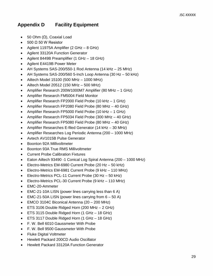
Appendix D Facility Equipment
• 50 Ohm (Ω), Coaxial Load • 500 Ω 50 W Resistor • Agilent 11975A Amplifier (2 GHz – 8 GHz) • Agilent 33120A Function Generator • Agilent 8449B Preamplifier (1 GHz – 18 GHz) • Agilent E4419B Power Meter • AH Systems SAS-200/550-1 Rod Antenna (14 kHz – 25 MHz) • AH Systems SAS-200/560 5-Inch Loop Antenna (30 Hz – 50 kHz) • Ailtech Model 15100 (500 MHz – 1000 MHz) • Ailtech Model 20512 (150 MHz – 500 MHz) • Amplifier Research 200W1000M7 Amplifier (80 MHz – 1 GHz) • Amplifier Research FM5004 Field Monitor • Amplifier Research FP2000 Field Probe (10 kHz – 1 GHz) • Amplifier Research FP2080 Field Probe (80 MHz – 40 GHz) • Amplifier Research FP5000 Field Probe (10 kHz – 1 GHz) • Amplifier Research FP5034 Field Probe (300 MHz – 40 GHz) • Amplifier Research FP5080 Field Probe (80 MHz – 40 GHz) • Amplifier Researches E-filed Generator (14 kHz – 30 MHz) • Amplifier Researches Log Periodic Antenna (200 – 1000 MHz) • Avtech AV1015B Pulse Generator • Boonton 92A Millivoltmeter • Boonton 93A True RMS Millivoltmeter • Current Probe Calibration Fixtures • Eaton Ailtech 93490 -1 Conical Log Spiral Antenna (200 – 1000 MHz) • Electro-Metrics EM-6980 Current Probe (20 Hz – 50 kHz) • Electro-Metrics EM-6981 Current Probe (9 kHz – 110 MHz) • Electro-Metrics PCL-11 Current Probe (30 Hz – 50 kHz) • Electro-Metrics PCL-30 Current Probe (9 kHz – 110 MHz) • EMC-20-Ammeter • EMC-21-10A LISN (power lines carrying less than 6 A) • EMC-21-50A LISN (power lines carrying from 6 – 50 A) • EMCO 3104C Biconical Antenna (20 – 200 MHz) • ETS 3106 Double Ridged Horn (200 MHz – 2 GHz) • ETS 3115 Double Ridged Horn (1 GHz – 18 GHz) • ETS 3117 Double Ridged Horn (1 GHz – 18 GHz) • F. W. Bell 6010 Gaussmeter With Probe • F. W. Bell 9500 Gaussmeter With Probe • Fluke Digital Voltmeter • Hewlett Packard 200CD Audio Oscillator • Hewlett Packard 33120A Function Generator
JSC-XXXXX
30
• Hewlett Packard 436A Power Meter • Hewlett Packard 438A Power Meter • Hewlett Packard 651A Test Oscillator (10 Hz – 10 MHz) • Hewlett Packard 8447 Preamplifier (100 kHz – 1.3 GHz) • Hewlett Packard 8562A Spectrum Analyzer (40 Hz – 22 GHz) • Hewlett Packard 8566B Spectrum Analyzer (30 Hz – 22 GHz) • Hewlett Packard 8582B Automatic Spectrum Analyzer System • Hewlett Packard 8663A Signal Generator (150 kHz – 2.0 GHz) • Hewlett Packard 8672A Signal Generator (2.0 GHz – 18 GHz) • Hewlett Packard 8673B Signal Generator (2.0 GHz – 26 GHz) • Hewlett Packard E7405A (9 kHz – 26.5 GHz) • High-Pass Filters, Low-Pass Filters, Single-Frequency Rejection Networks, and Broadband
Attenuators • Hughes TWTA (1000 MHz – 2000 MHz) • Hughes TWTA (2000 MHz – 4000 MHz) • IFI CMC250 Amplifier (80 MHz – 1 GHz) • IFI SCCX100 Amplifier (10 kHz – 250 MHz) • IFI SCCX75 Amplifier (10 kHz – 220 MHz) • IFI SMX10 Power Amplifier (10 kHz – 1 GHz) • IFI T1875-500 Amplifier (7.5 GHz – 18 GHz) • IFI T251-500 Amplifier (1 GHz – 2.5 GHz) • IFI T7525-500 Amplifier (2.5 GHz – 7.5 GHz) • Test Signal Monitor Network Model JSF- 3 • JSF-2 Coupling Capacitor Network • LeCroy 9310AM Oscilloscope • LeCroy LT374 Oscilloscope • LogiMetrics A600/C Amplifier (4 GHz – 8 GHz) • LogiMetrics A600/L Amplifier (1 GHz – 2 GHz) • LogiMetrics A650/S Amplifier (2 GHz – 4 GHz) • LogiMetrics A651/IJ Amplifier (8 GHz – 18 GHz) • Model EAS-2 Test Lead Routing Standard (TLRS) • Narda 50 Ω Temination (DC – 18 GHz) • Narda Directional Couplers • P/N SED38115052-301 Line Impedance Stabilization Network (LISN) (6A – 20 A) • P/N SED38115052-303 Line Impedance Stabilization Network (LISN) (below 6 A) • Philips PM5786B Pulse Generator • Plotter • Power Isolation Transformer • Reference Magnet • Rohde & Schwarz ESI26 Receiver System or Equivalent • Rohde & Schwarz SMGU Signal Generator (100 kHz – 2160 MHz) • Rohde & Schwarz SMP22 Signal Generator (2 GHz – 20 GHz) • Rohde & Schwarz SMT03 Signal Generator (5 kHz – 3 GHz)
JSC-XXXXX
31
• RF Power Labs Amplifier (1-525 MHz) • Solar 2055-1 DC Power Line Spike Generator • Solar 6220-1 Isolation Transformer • Solar 6512-106R Line Stabilization Capacitor (LSC) • Solar 6550-1 Power Sweep Generator • Solar 6552-1A Audio Amplifier • Solar 7021-1 Phase Shift Network (AC power lines only) • Solar 8282-1 Transient Pulse Generator • Solar 8901-4-TS-100-BP (power lines carrying from 6 – 50 A) • Solar 8901-4-TS-15-BP (power lines carrying less than 6 A) • Solar 8904-4-TS-15-BP Line Impedance Stabilization Network • Solar 9123-1N Current Probe (10 kHz – 500 MHz) • Solar 9133-1 10 µF Delta Capacitor • Solar 9142-1N Injection Probe (2 MHz – 450 MHz) • Solar 9225-0.5 Precision Resistor Assembly • Solar 9229-1 Loop Sensor • Solar 9230-1 Loop Antenna (30 Hz – 100 kHz) • Solar 9233-50-TS-50-N Line Impedance Simulation Network • Solar 9238-10-TS-50-BNC Line Impedance Stabilization Network • Solar 9335-2 Multiple Port Coupling Device • Solar 9354-1 Transient Pulse Generator with Frequency Modules • Solar 9355-1 Pulse Generator • Solar Transient Generator Model 6471-1 • Sorensen DCR 160-30T Power Supply • Sorensen SRL 60-35 Power Supply • Standard Gain Horn Antenna SA 12-12 (12 – 18 GHz) • Standard Gain Horn Antenna SA 12-3.9 (3.9 – 5.8 GHz) • Standard Gain Horn Antenna SA 12-5.8 (5.8 – 8.2 GHz) • Standard Gain Horn Antenna SA 12-8.2 (8.2 – 12.4 GHz) • Stoddart 93491-2 Conical Log Spiral Antenna (1000 – 10,000 MHz) • Stoddart Horn Antenna 91888-1 (1.0 – 2.3 GHz) • Stoddart Horn Antenna 91889-1 (2.3 – 4.4 GHz) • Tektronix 754D Oscilloscope • TESEO Fiberoptic Image 200 Color CCTV System • TMD PTC6341 Amplifier (1 GHz – 2.8 GHz) • Varian VTX6981F1 (8000 MHz – 12.4 GHz) • Varian VZC6961K1DL (4000 MHz – 8000 MHz) • Varian VZU6991K1D (12 GHz – 18 GHz) • Zero Gauss Chamber
JSC-XXXXX
32
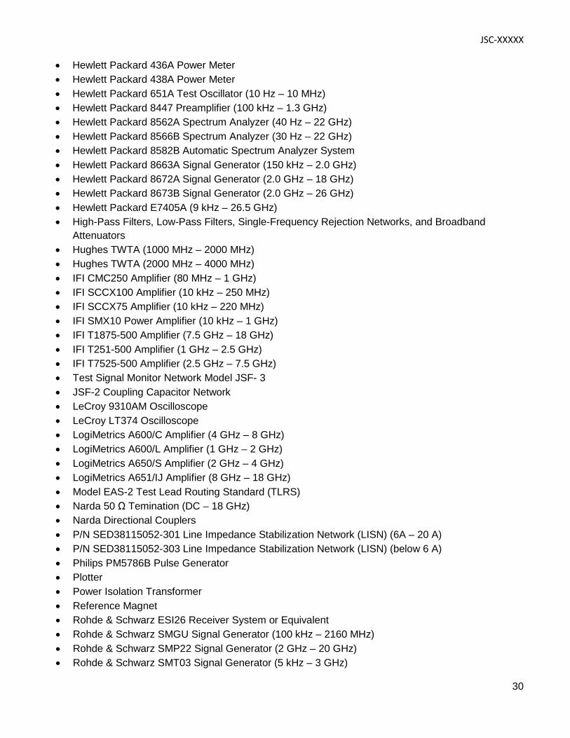
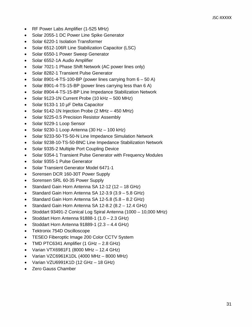
Appendix E Sample Test Configurations
Electromagnetic Interference Test for Robonaut 2
Radiated Susceptibility for Potable Water Dispenser
JSC-XXXXX
33
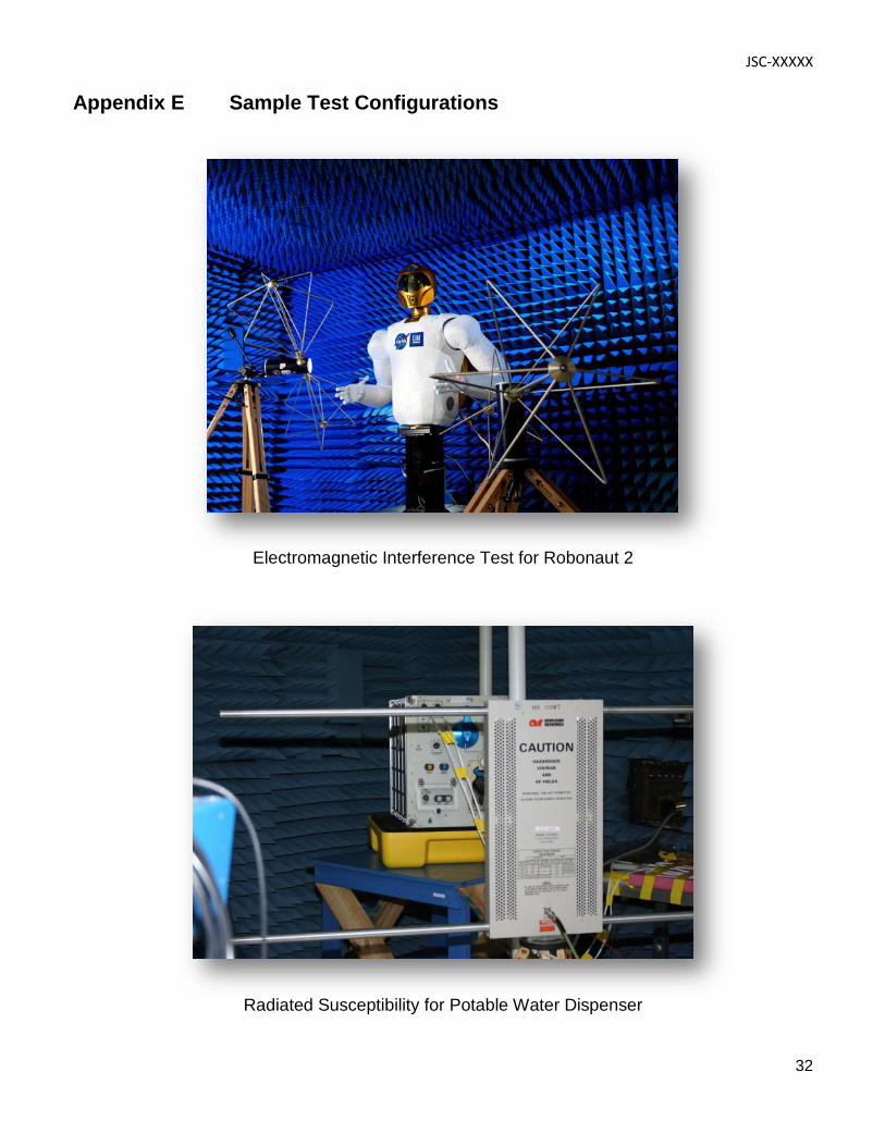
Electromagnetic Interference Test for Treadmill 2
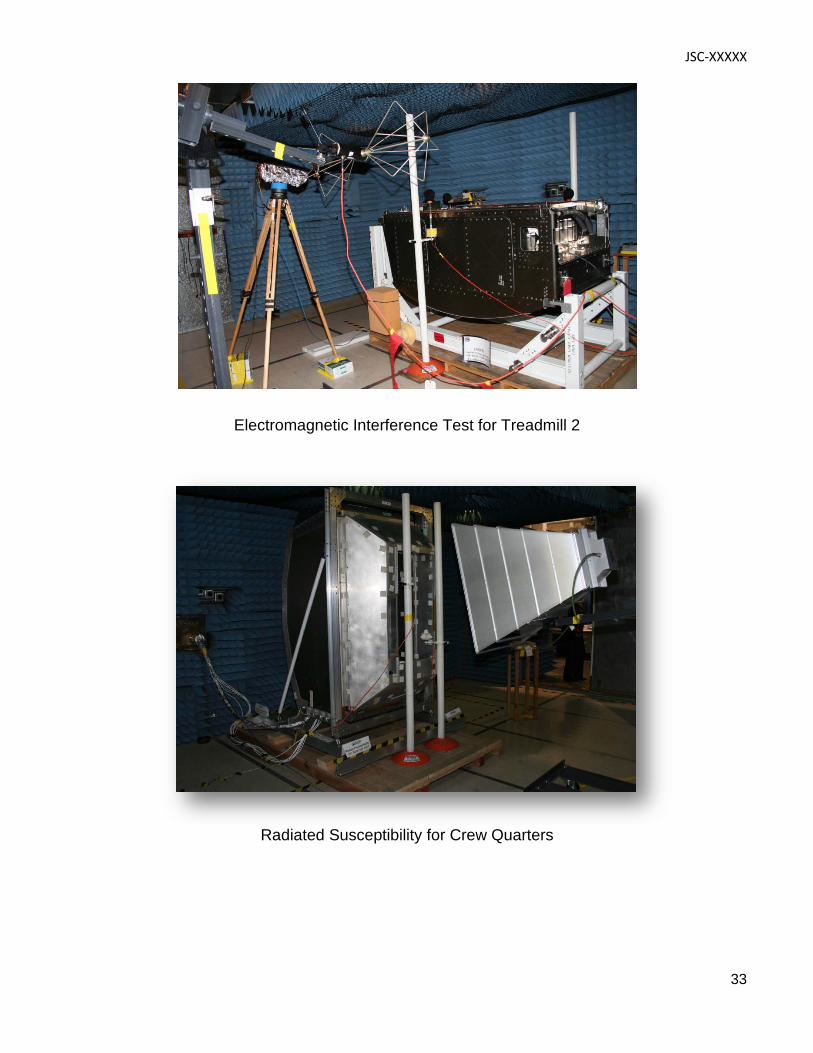
Radiated Susceptibility for Crew Quarters