Embed Size (px)
Citation preview
[EPC 431/3]
-1-
…2/-
UNIVERSITI SAINS MALAYSIA
First Semester Examination
Academic Session 2009/2010
Peperiksaan Semester Pertama
Sidang Akademik 2009/2010
NOVEMBER 2009
EPC 431/3 - ROBOTICS AND AUTOMATION
ROBOTIK DAN AUTOMASI
Duration : 3 hours
Masa : 3 jam
INSTRUCTION TO CANDIDATE :
ARAHAN KEPADA CALON :
Please check that this paper contains TWELVE (12) printed pages and FIVE (5)
questions before you begin the examination.
Sila pastikan bahawa kertas soalan ini mengandungi DUA BELAS (12) mukasurat dan
LIMA (5) soalan yang bercetak sebelum anda memulakan peperiksaan.
Answer ALL questions.
Jawab SEMUA soalan.
You may answer in English or Malay.
Calon boleh menjawab dalam Bahasa Inggeris atau Bahasa Malaysia.
Each question must begin from a new page.
Setiap soalan mestilah dimulakan pada mukasurat yang baru.
In the event of any discrepancies, the English version shall be used.
Sekiranya terdapat sebarang percanggahan pada soalan peperiksaan,versi Bahasa Inggeris
hendaklah diguna pakai.
[EPC 431/3]
-2-
…3/-
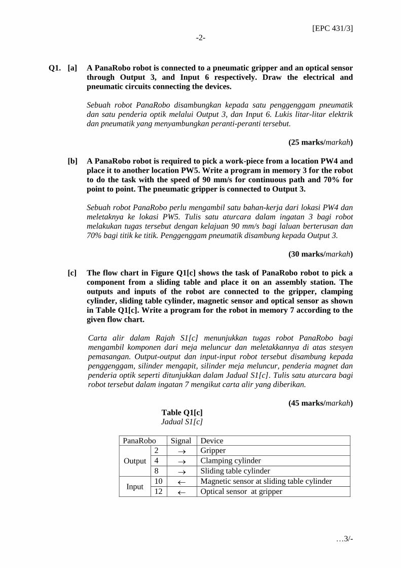
Q1. [a] A PanaRobo robot is connected to a pneumatic gripper and an optical sensor
through Output 3, and Input 6 respectively. Draw the electrical and
pneumatic circuits connecting the devices.
Sebuah robot PanaRobo disambungkan kepada satu penggenggam pneumatik
dan satu penderia optik melalui Output 3, dan Input 6. Lukis litar-litar elektrik
dan pneumatik yang menyambungkan peranti-peranti tersebut.
(25 marks/markah)
[b] A PanaRobo robot is required to pick a work-piece from a location PW4 and
place it to another location PW5. Write a program in memory 3 for the robot
to do the task with the speed of 90 mm/s for continuous path and 70% for
point to point. The pneumatic gripper is connected to Output 3.
Sebuah robot PanaRobo perlu mengambil satu bahan-kerja dari lokasi PW4 dan
meletaknya ke lokasi PW5. Tulis satu aturcara dalam ingatan 3 bagi robot
melakukan tugas tersebut dengan kelajuan 90 mm/s bagi laluan berterusan dan
70% bagi titik ke titik. Penggenggam pneumatik disambung kepada Output 3.
(30 marks/markah)
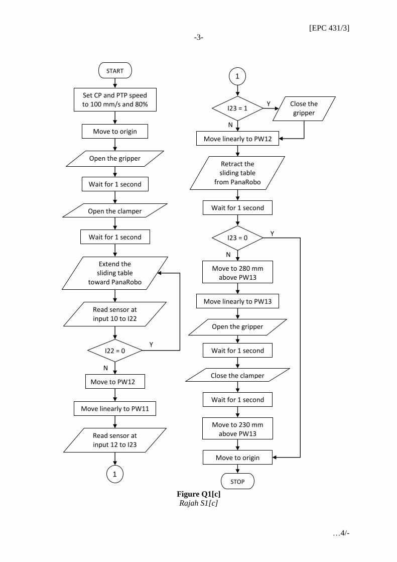
[c] The flow chart in Figure Q1[c] shows the task of PanaRobo robot to pick a
component from a sliding table and place it on an assembly station. The
outputs and inputs of the robot are connected to the gripper, clamping
cylinder, sliding table cylinder, magnetic sensor and optical sensor as shown
in Table Q1[c]. Write a program for the robot in memory 7 according to the
given flow chart.
Carta alir dalam Rajah S1[c] menunjukkan tugas robot PanaRobo bagi
mengambil komponen dari meja meluncur dan meletakkannya di atas stesyen
pemasangan. Output-output dan input-input robot tersebut disambung kepada
penggenggam, silinder mengapit, silinder meja meluncur, penderia magnet dan
penderia optik seperti ditunjukkan dalam Jadual S1[c]. Tulis satu aturcara bagi
robot tersebut dalam ingatan 7 mengikut carta alir yang diberikan.
(45 marks/markah)
Table Q1[c]
Jadual S1[c]
PanaRobo Signal Device
Output
2 Gripper
4 Clamping cylinder
8 Sliding table cylinder
Input 10 Magnetic sensor at sliding table cylinder
12 Optical sensor at gripper
[EPC 431/3]
-3-
…4/-
Figure Q1[c]
Rajah S1[c]
N
N
Y
Y
START
Set CP and PTP speed to 100 mm/s and 80%
Open the gripper
Wait for 1 second
Wait for 1 second
I23 = 1 Close the gripper
Move to origin
Open the clamper
Extend the sliding table
toward PanaRobo
Read sensor at input 10 to I22
I22 = 0
Move to PW12
Move linearly to PW11
Read sensor at input 12 to I23
Move linearly to PW12
Retract the sliding table
from PanaRobo
1
1
N
Y I23 = 0
Move to 280 mm above PW13
Wait for 1 second
Move linearly to PW13
Open the gripper
Wait for 1 second
Close the clamper
Wait for 1 second
Move to 230 mm above PW13
STOP
Move to origin
[EPC 431/3]
-4-
…5/-
Q2. [a] A gantry robot has z and r axes driven by stepper motors with 1.8 per step
resolution. The first motor is connected to the z axis through a ball screw
with 6 mm pitch. The second motor is connected to the r axis through a gear
box with 15:1 ratio.
Sebuah robot gantri mempunyai paksi z dan r yang dipacu oleh motor pelangkah
dengan resolusi 1.8º per langkah. Motor pertama disambung kepada paksi z
melalui satu skrew berbola dengan anggul 6 mm. Motor kedua disambung kepada
paksi r melalui kotak gear dengan nisbah 15:1.
(i) Calculate the required unit value to convert from step to mm and
degree for each axis.
Kira nilai unit diperlukan bagi menukar dari langkah ke mm dan darjah
untuk setiap paksi.
(ii) Calculate the operating speed in Hz if the z and r axes are required to
move 0.4 m/s and 90 degree/s respectively.
Kira kelajuan operasi dalam Hz jika paksi z dan r masing-masing perlu
bergerak 0.4 m/s dan 90 darjah/s.
(iii) Write the commands required to set the unit and operating speed in the
z and r motor controller.
Tuliskan arahan yang perlu bagi menentukan unit dan laju operasi dalam
pengawal motor z dan r.
(30 marks/markah)
[b] A gantry robot is required to move the x and y axes simultaneously to a
position 2.1 and 2.6 m relative to the home respectively. Then, it moves the y
axis to a distance -1.2 m from the current position. Finally, it moves the x
axis to a distance 1.6 m from the current position. Sketch and give the
coordinates of the robot motion. Write a program in memory 6 for that task.
Sebuah robot gantri diperlukan bagi menggerakkan paksi x dan y serentak ke satu
posisi masing-masing 2.1 dan 2.6 m merujuk kepada asalan. Kemudian, ia
menggerakkan paksi y ke satu jarak -1.2 m dari posisi semasa. Akhirnya, ia
menggerakkan paksi x ke satu jarak 1.6 m dari posisi semasa. Lakar dan berikan
koordinat-koordinat pergerakan robot. Tulis satu aturcara dalam ingatan 6 untuk
tugas tersebut.
(20 marks/markah)
[EPC 431/3]
-5-
…6/-
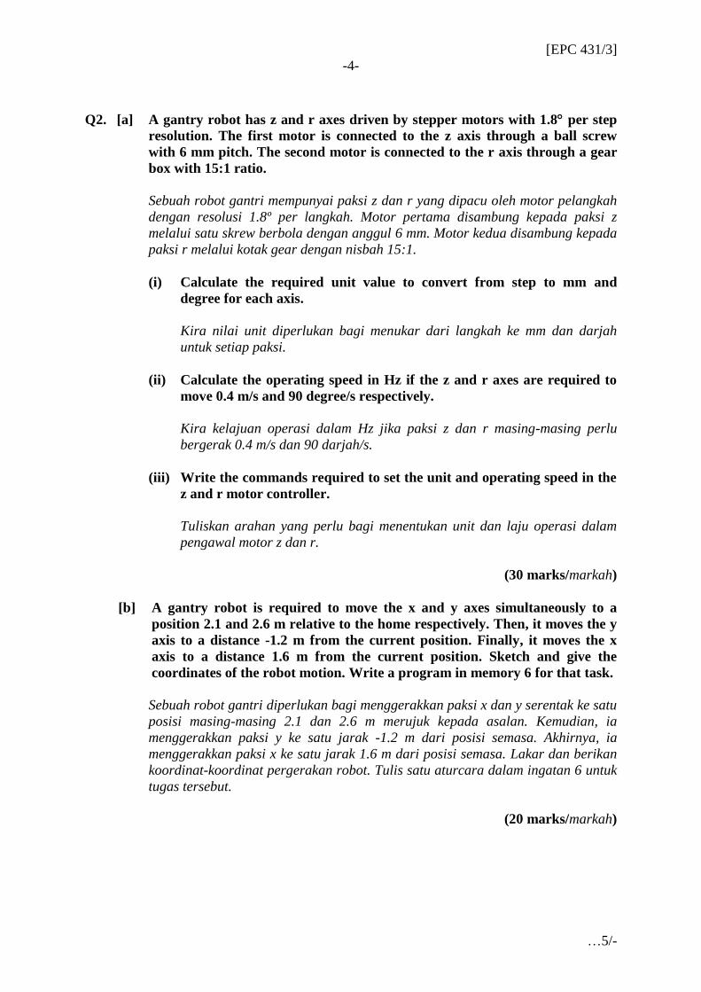
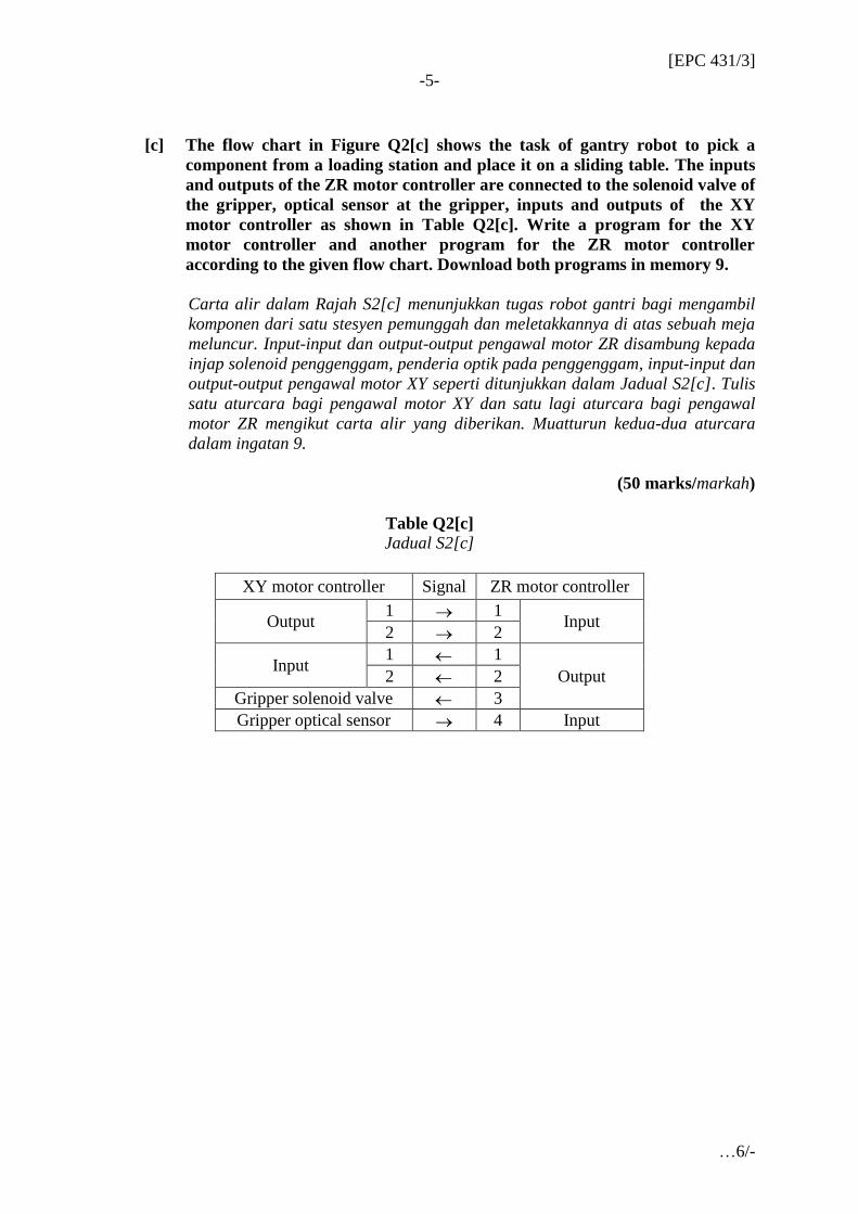
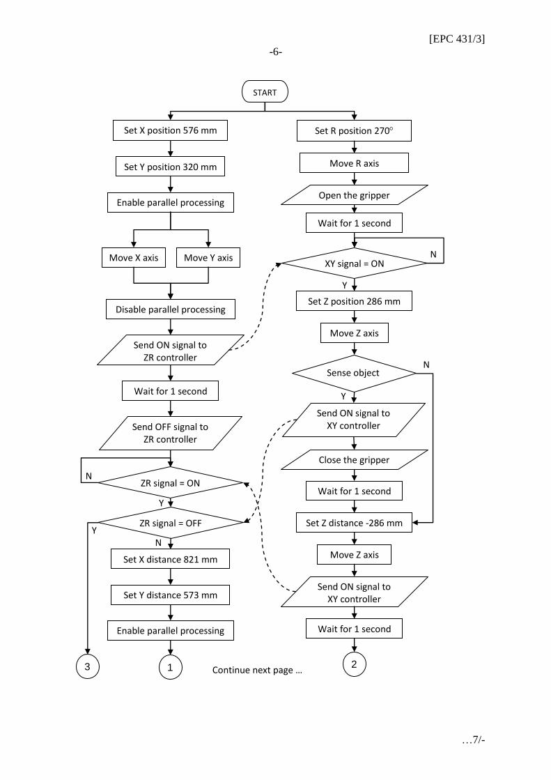
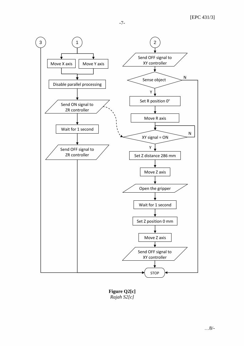
[c] The flow chart in Figure Q2[c] shows the task of gantry robot to pick a
component from a loading station and place it on a sliding table. The inputs
and outputs of the ZR motor controller are connected to the solenoid valve of
the gripper, optical sensor at the gripper, inputs and outputs of the XY
motor controller as shown in Table Q2[c]. Write a program for the XY
motor controller and another program for the ZR motor controller
according to the given flow chart. Download both programs in memory 9.
Carta alir dalam Rajah S2[c] menunjukkan tugas robot gantri bagi mengambil
komponen dari satu stesyen pemunggah dan meletakkannya di atas sebuah meja
meluncur. Input-input dan output-output pengawal motor ZR disambung kepada
injap solenoid penggenggam, penderia optik pada penggenggam, input-input dan
output-output pengawal motor XY seperti ditunjukkan dalam Jadual S2[c]. Tulis
satu aturcara bagi pengawal motor XY dan satu lagi aturcara bagi pengawal
motor ZR mengikut carta alir yang diberikan. Muatturun kedua-dua aturcara
dalam ingatan 9.
(50 marks/markah)
Table Q2[c]
Jadual S2[c]
XY motor controller Signal ZR motor controller
Output 1 1
Input 2 2
Input 1 1
Output 2 2
Gripper solenoid valve 3
Gripper optical sensor 4 Input
[EPC 431/3]
-6-
…7/-
START
Set X position 576 mm
Disable parallel processing
Move X axis
Set Y position 320 mm
Send ON signal to ZR controller
Send OFF signal to ZR controller
Set X distance 821 mm
Set Y distance 573 mm
1
N
Y
Sense object
Enable parallel processing
Move Y axis
Wait for 1 second
Enable parallel processing
Set R position 270
Move Z axis
Move R axis
2
Set Z position 286 mm
Open the gripper
Close the gripper
Wait for 1 second
Set Z distance -286 mm
Move Z axis
Send ON signal to XY controller
Wait for 1 second
Wait for 1 second
Continue next page …
XY signal = ON
N
Y
ZR signal = ON
Y
N
ZR signal = OFF
N
3
Y
Send ON signal to XY controller
[EPC 431/3]
-7-
…8/-
Figure Q2[c]
Rajah S2[c]
STOP
Move Y axis
Disable parallel processing
Send ON signal to ZR controller
Send OFF signal to ZR controller
1
Wait for 1 second
Set R position 0
Move Z axis
Move R axis
2
Set Z distance 286 mm
3
Open the gripper
Wait for 1 second
Set Z position 0 mm
Move Z axis
Move X axis
XY signal = ON
Y
N
Send OFF signal to XY controller
Sense object
Send OFF signal to XY controller
N
Y
[EPC 431/3]
-8-
…9/-
Q3. [a] A Programmable Logic Controller (PLC) is used as a master controller to
synchronize PanaRobo controller. A pick and place program has been loaded
into memory 7 of the PanaRobo controller. Build a ladder diagram as a
subroutine for the PLC to execute the program in the PanaRobo controller.
State the required input/output connections between the PLC and the
PanaRobo controller.
Sebuah pengawal logik bolehaturcara (PLC) diguna sebagai pengawal induk bagi
menyegerak pengawal PanaRobo. Satu aturcara ambil dan letak telah dimuatkan
ke dalam memori 7 pengawal PanaRobo. Bina satu rajah tetangga sebagai satu
subrutin bagi PLC melaksanakan aturcara dalam pengawal PanaRobo. Nyatakan
sambungan input/output diperlukan antara PLC dan pengawal PanaRobo.
(30 marks/markah)
[b] A Programmable Logic Controller (PLC) is used as a master controller to
synchronize two stepper motor controllers. A program for gantry robot to
pick and place a component has been loaded into memory 6 of each motor
controller. Build a ladder diagram as a subroutine for the PLC to execute the
program in both motor controllers. State the required input/output
connection between the PLC and both motor controllers.
Sebuah pengawal logik bolehaturcara (PLC) diguna sebagai pengawal induk bagi
menyegerakkan dua buah pengawal motor pelangkah. Satu aturcara bagi robot
gantri mengambil dan letak satu komponen telah dimuatkan ke dalam memori 6
setiap pengawal motor. Bina satu rajah tetangga sebagai satu subrutin bagi PLC
melaksanakan aturcara dalam kedua-dua pengawal motor. Nyatakan sambungan
input/output diperlukan antara PLC dan kedua-dua pengawal motor.
(30 marks/markah)
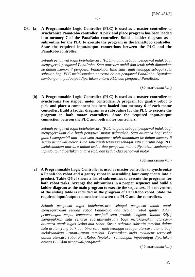
[c] A Programmable Logic Controller is used as master controller to synchronize
a PanaRobo robot and a gantry robot in assembling four components into a
product. Table Q4[c] shows a list of subroutines to execute the programs for
both robot tasks. Arrange the subroutines in a proper sequence and build a
ladder diagram as the main program to execute the sequences. The movement
of the sliding table is included in the program of PanaRobo robot. State the
required input/output connections between the PLC and the controllers.
Sebuah pengawal logik bolehaturcara sebagai pengawal induk untuk
menyegerakkan sebuah robot PanaRobo dan sebuah robot gantri dalam
pemasangan empat komponen menjadi satu produk lengkap. Jadual S4[c]
menunjukkan satu senarai subrutin-subrutin bagi melaksanakan aturcara-
aturcara untuk tugas kedua-dua robot. Susun subrutin-subrutin tersebut dalam
satu urutan yang baik dan bina satu rajah tetangga sebagai aturcara utama bagi
melaksanakan urutan-urutan tersebut. Pergerakan meja meluncur termasuk
dalam aturcara robot PanaRobo. Nyatakan sambungan input/output diperlukan
antara PLC dan pengawal-pengawal.
(40 marks/markah)
[EPC 431/3]
-9-
…10/-
Table Q3[c]
Jadual S3[c]
Subroutine Robot Component From To Duration
(Seconds)
Preceding
subroutine
11 Gantry A A loading
station
A sliding
table
44 None
12 Gantry B B loading
station
B sliding
table
36 None
13 Gantry C C loading
station
C sliding
table
41 None
21 PanaRobo A A sliding
table
Assembly
station
16 11
22 PanaRobo B B sliding
table
Assembly
station on A
9 12
21
23 PanaRobo C C sliding
table
Assembly
station on B
12 13
22
Q4. [a] State SEVEN main components of a robot.
Nyatakan TUJUH komponen utama sebuah robot.
(20 marks/markah)
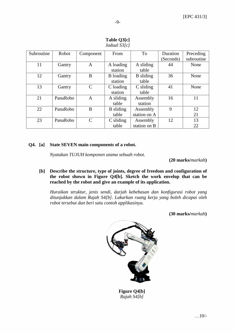
[b] Describe the structure, type of joints, degree of freedom and configuration of
the robot shown in Figure Q4[b]. Sketch the work envelop that can be
reached by the robot and give an example of its application.
Huraikan struktur, jenis sendi, darjah kebebasan dan konfigurasi robot yang
ditunjukkan dalam Rajah S4[b]. Lakarkan ruang kerja yang boleh dicapai oleh
robot tersebut dan beri satu contoh applikasinya.
(30 marks/markah)
Figure Q4[b]
Rajah S4[b]
[EPC 431/3]
-10-
…11/-
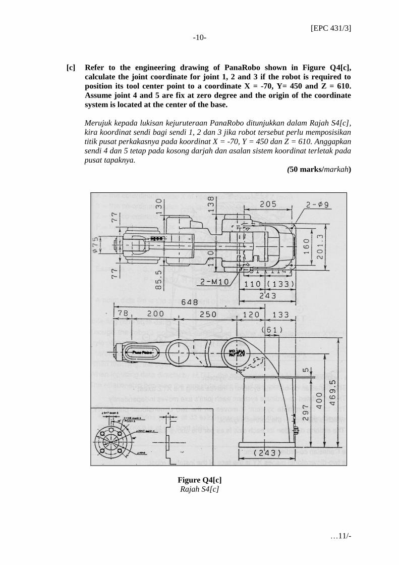
[c] Refer to the engineering drawing of PanaRobo shown in Figure Q4[c],
calculate the joint coordinate for joint 1, 2 and 3 if the robot is required to
position its tool center point to a coordinate X = -70, Y= 450 and Z = 610.
Assume joint 4 and 5 are fix at zero degree and the origin of the coordinate
system is located at the center of the base.
Merujuk kepada lukisan kejuruteraan PanaRobo ditunjukkan dalam Rajah S4[c],
kira koordinat sendi bagi sendi 1, 2 dan 3 jika robot tersebut perlu memposisikan
titik pusat perkakasnya pada koordinat X = -70, Y = 450 dan Z = 610. Anggapkan
sendi 4 dan 5 tetap pada kosong darjah dan asalan sistem koordinat terletak pada
pusat tapaknya.
(50 marks/markah)
Figure Q4[c]
Rajah S4[c]
[EPC 431/3]
-11-
…12/-
Q5. [a] With the aid of a sketch, describe the degree of freedom of a spherical joint.
How can this type of joint be modeled?
Dengan bantuan lakaran, huraikan darjah kebebasan satu sendi bersfera.
Bagaimana sendi jenis ini boleh dimodelkan?
(20 marks/markah)
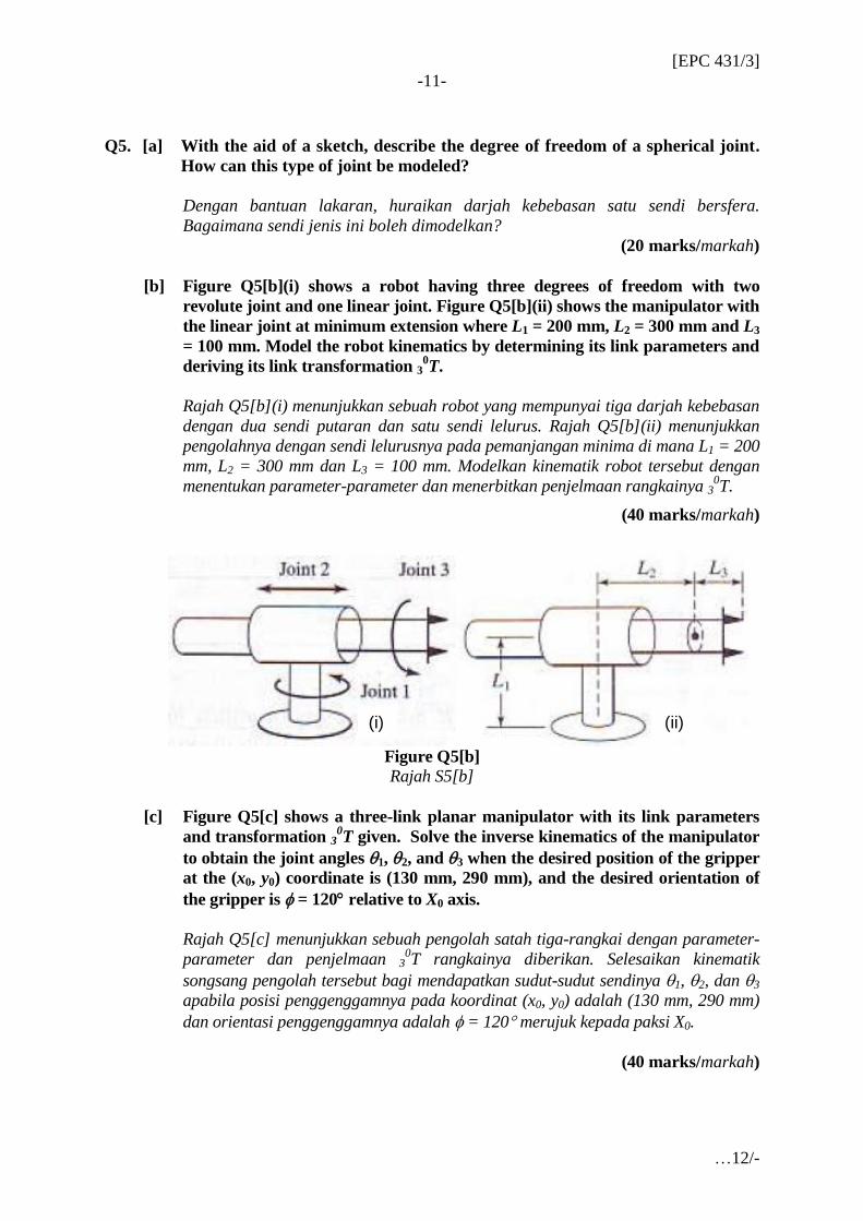
[b] Figure Q5[b](i) shows a robot having three degrees of freedom with two
revolute joint and one linear joint. Figure Q5[b](ii) shows the manipulator with
the linear joint at minimum extension where L1 = 200 mm, L2 = 300 mm and L3
= 100 mm. Model the robot kinematics by determining its link parameters and
deriving its link transformation 30T.
Rajah Q5[b](i) menunjukkan sebuah robot yang mempunyai tiga darjah kebebasan
dengan dua sendi putaran dan satu sendi lelurus. Rajah Q5[b](ii) menunjukkan
pengolahnya dengan sendi lelurusnya pada pemanjangan minima di mana L1 = 200
mm, L2 = 300 mm dan L3 = 100 mm. Modelkan kinematik robot tersebut dengan
menentukan parameter-parameter dan menerbitkan penjelmaan rangkainya 30T.
(40 marks/markah)
Figure Q5[b]
Rajah S5[b]
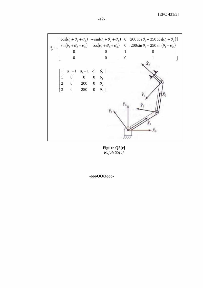
[c] Figure Q5[c] shows a three-link planar manipulator with its link parameters
and transformation 30T given. Solve the inverse kinematics of the manipulator
to obtain the joint angles 1, 2, and 3 when the desired position of the gripper
at the (x0, y0) coordinate is (130 mm, 290 mm), and the desired orientation of
the gripper is = 120 relative to X0 axis.
Rajah Q5[c] menunjukkan sebuah pengolah satah tiga-rangkai dengan parameter-
parameter dan penjelmaan 30T rangkainya diberikan. Selesaikan kinematik
songsang pengolah tersebut bagi mendapatkan sudut-sudut sendinya 1, 2, dan 3
apabila posisi penggenggamnya pada koordinat (x0, y0) adalah (130 mm, 290 mm)
dan orientasi penggenggamnya adalah = 120 merujuk kepada paksi X0.
(40 marks/markah)
(i) (ii)
[EPC 431/3]
-12-
…13/-
Figure Q5[c]
Rajah S5[c]
-oooOOOooo-
1000
0100
sin250sin2000cossin
cos250cos2000sincos
211321321
211321321
0
3
T
3
2
1
025003
020002
0001
11
iiii dai