Embed Size (px)
Citation preview
ACCESSORIES FOR HV CABLESWITH EXTRUDED INSULATION
Ref: WG 21.06 (TB 177)JTF 21.15 (TB 210)
TF B1.10 (Electra 212)
Henk Geene
Presentation overview
Accessories function Accessory design Accessory types Accessories main components Guide to the selection of accessories Tests on accessories Accessories installation Accessories maintenance
Accessories Function
Terminations:
Accessories that connect a cable to the grid
The grid can be either a transformer or a GIS or an overhead line
Joints:
Accessories that connect 2 or 3 cables together
The cables can be of the same type/construction or of differenttype/construction
Accessory Design
The development of an accessory involves the following design aspects:
Electrical design: the control of the electrical stresses at the cable screen interruption the control of electrical stresses within the accessory, mainly at interfaces
Mechanical design: the control of the mechanical stresses inside the accessory the control of stresses transferred to the accessory by the adjacent
cable and environment
Thermal design:avoid that the accessory, due to its generally larger dimensions,
becomes the hot spot for the cable system
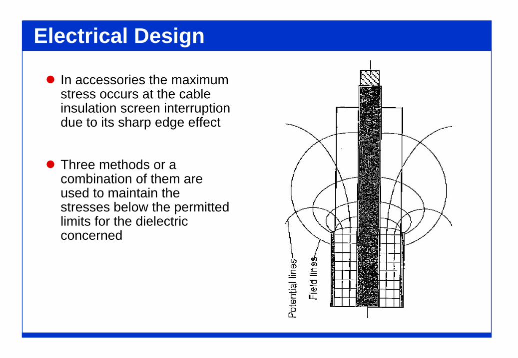
Electrical Design
In accessories the maximumstress occurs at the cableinsulation screen interruptiondue to its sharp edge effect
Three methods or acombination of them areused to maintain thestresses below the permittedlimits for the dielectricconcerned
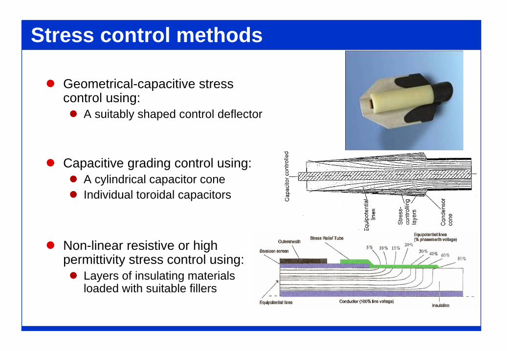
Stress control methods
Geometrical-capacitive stress control using: A suitably shaped control deflector
Capacitive grading control using: A cylindrical capacitor cone Individual toroidal capacitors
Non-linear resistive or high permittivity stress control using: Layers of insulating materials
loaded with suitable fillers
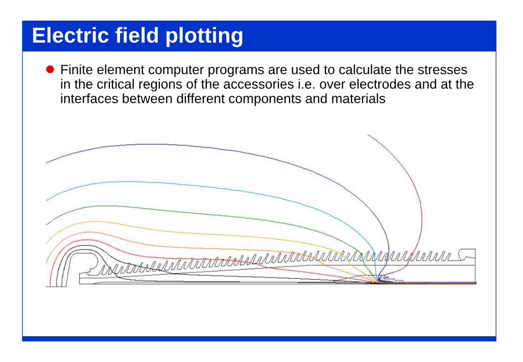
Electric field plotting Finite element computer programs are used to calculate the stresses
in the critical regions of the accessories i.e. over electrodes and at the interfaces between different components and materials
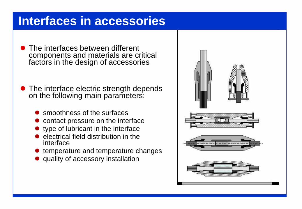
Interfaces in accessories
The interfaces between different components and materials are critical factors in the design of accessories
The interface electric strength depends on the following main parameters:
smoothness of the surfaces contact pressure on the interface type of lubricant in the interface electrical field distribution in the
interface temperature and temperature changes quality of accessory installation
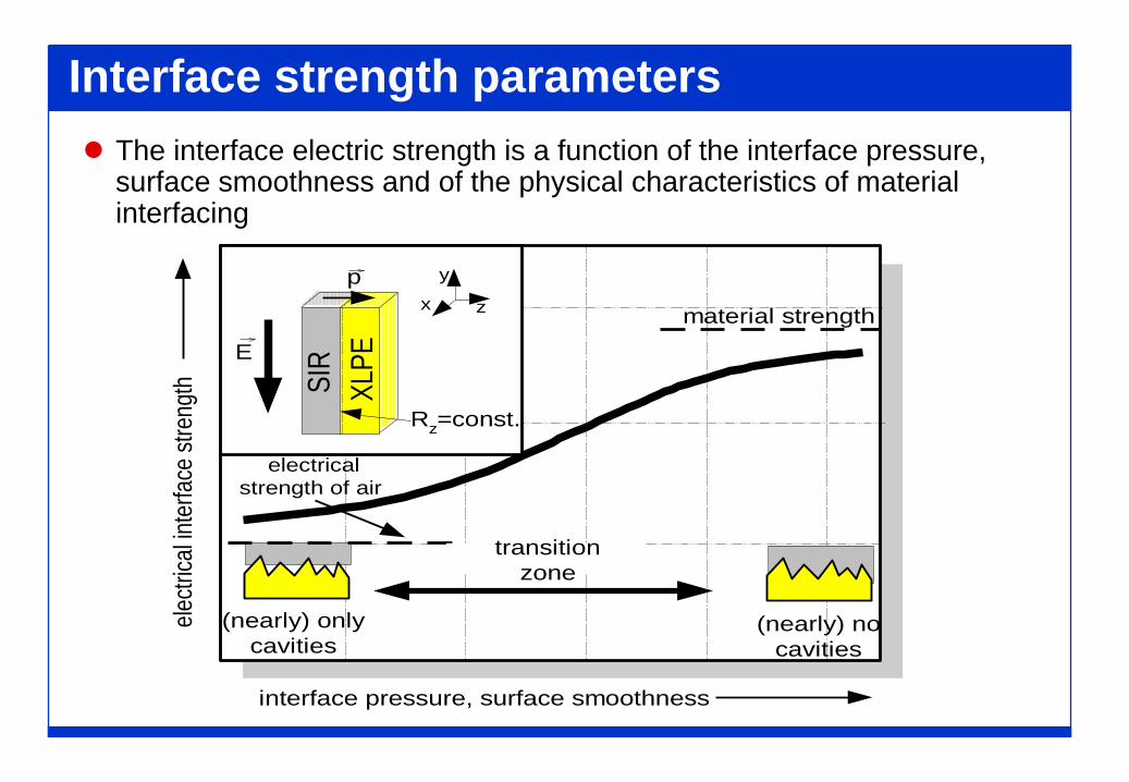
Interface strength parameters The interface electric strength is a function of the interface pressure,
surface smoothness and of the physical characteristics of material interfacing
interface pressure, surface smoothness
E
Rz=const.
x
y
z
XLPE
SIR
p
electr
ical in
terfa
ce st
reng
th
(nearly) nocavities
(nearly) onlycavities
material strength
electricalstrength of air
transitionzone
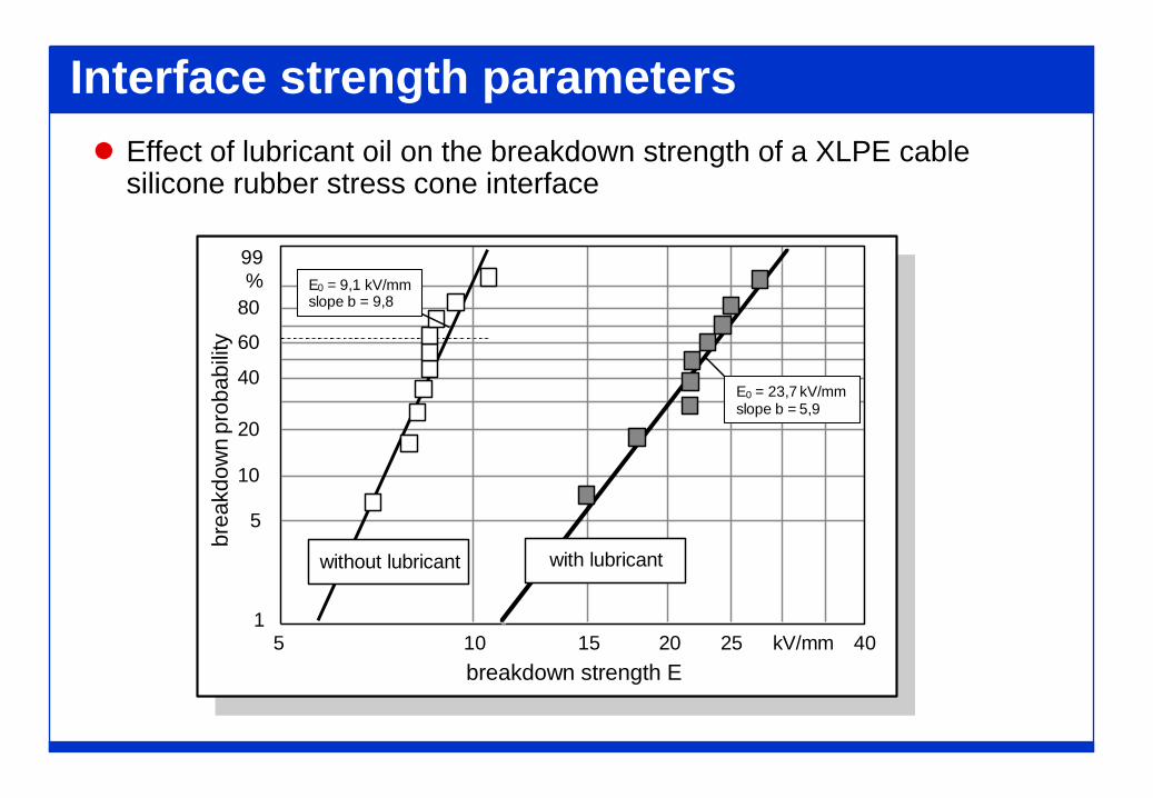
Interface strength parameters Effect of lubricant oil on the breakdown strength of a XLPE cable
silicone rubber stress cone interface
breakdown strength E
brea
kdow
n pr
obab
ility
1
5
10
20
40
60
80%99
405 10 15 20 25 kV/mm
E0 = 9,1 kV/mmslope b = 9,8
with lubricantwithout lubricant
5,9E0 = 23,7 kV/mmslope b = 5,9
Mechanical Design The accessory components must support the thermal
contractions and expansions due to the variation of the currentcirculating in the conductor
Joints and terminations must also be designed to withstand thethermo-mechanical forces transferred by the adjacent cable/swhich depend on the cable system installation condition (rigid orflexible)
Terminations must support the forces transferred by theapparatus to which they are connected
If the accessory is filled with a fluid it must be able to support thepressure exerted by the fluid
Accessories must support the stresses from the environment(cantilever, vibrations, seismic, ambient stresses, etc.)
Accessory support systems (e.g. joint racking, terminationsupport) must take into account the mechanical accessory designto secure their compatibility.
Electrical Connections and Link Boxes
Joint electrical connections must also consider control of metallic shield (screen and sheath connections for the purposes of single point bonding or cross bonding
Shield interrupts must withstand nominal standing voltages and impulse voltages that may occur during faults
Joints must have electrical connections that permit connections to link boxes
Link boxes: Have removable links to isolate the cable metallic shield/sheath for
periodic testing Connection of the ungrounded end to sheath voltage limiters,
similar to 3-6 kV surge arrestors Bonding cables are needed to connect shield/sheaths to link
boxes. Typically, unshielded, single-phase cables or concentric bonding cables are used with 600V to 1000V insulation
Thermal Design
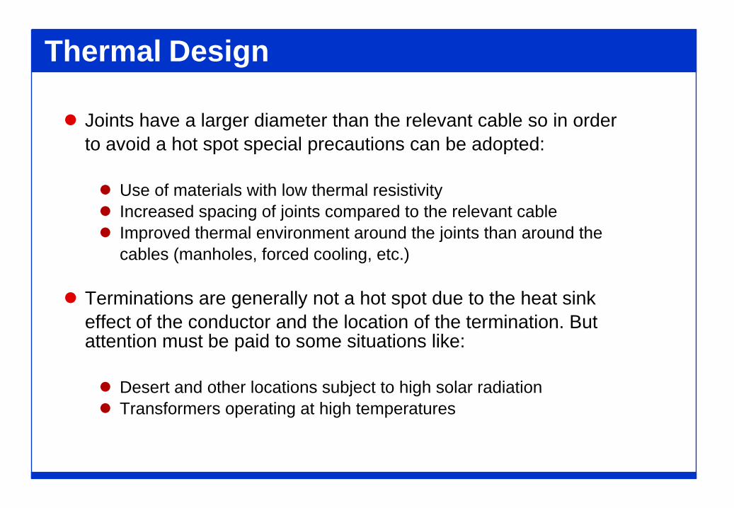
Joints have a larger diameter than the relevant cable so in orderto avoid a hot spot special precautions can be adopted:
Use of materials with low thermal resistivity Increased spacing of joints compared to the relevant cable Improved thermal environment around the joints than around the
cables (manholes, forced cooling, etc.)
Terminations are generally not a hot spot due to the heat sinkeffect of the conductor and the location of the termination. But attention must be paid to some situations like:
Desert and other locations subject to high solar radiation Transformers operating at high temperatures
Thermal Design
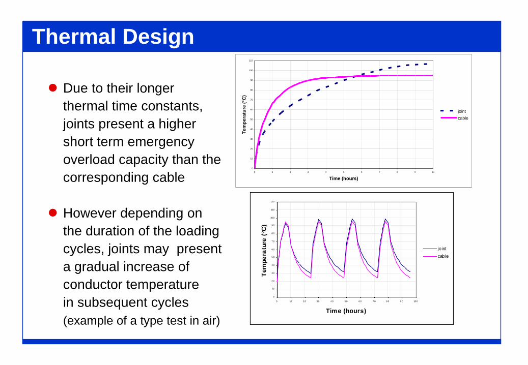
Due to their longerthermal time constants,joints present a highershort term emergencyoverload capacity than thecorresponding cable
However depending onthe duration of the loadingcycles, joints may presenta gradual increase ofconductor temperaturein subsequent cycles(example of a type test in air)
0
10
20
30
40
50
60
70
80
90
100
110
0 1 2 3 4 5 6 7 8 9 10
Time (hours)
Tem
pera
ture
(°C
)
jointcable
0
10
2 0
3 0
4 0
5 0
6 0
7 0
8 0
9 0
10 0
110
12 0
0 10 2 0 3 0 4 0 5 0 6 0 7 0 8 0 9 0 10 0
Time (hours)
Tem
pera
ture
(°C
)
jointcable
ACCESSORY TYPES
JOINT TYPES
Straight joints: connecting two cables of the same insulation type
Transition joints: connecting two cables of different insulation types
Y branch joints: connecting three cables
Straight joints
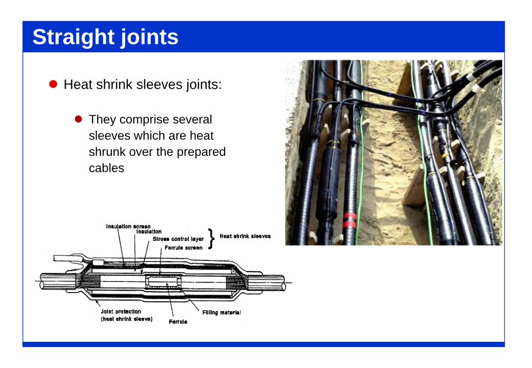
Heat shrink sleeves joints:
They comprise severalsleeves which are heatshrunk over the preparedcables
Straight Joints
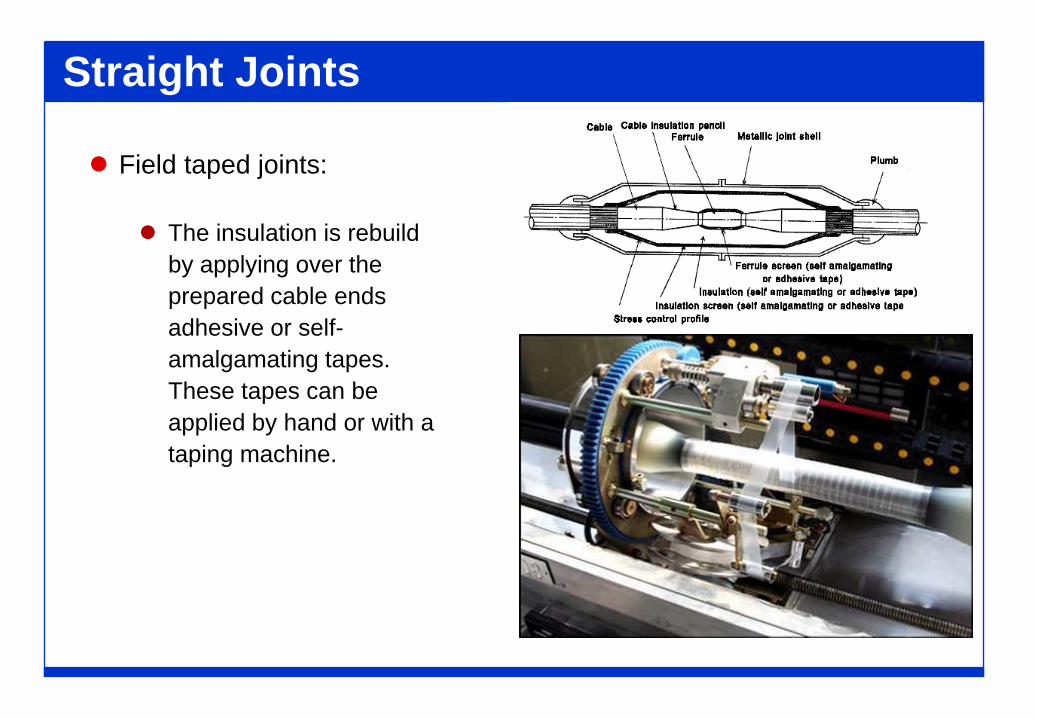
Field taped joints:
The insulation is rebuildby applying over theprepared cable endsadhesive or self-amalgamating tapes.These tapes can beapplied by hand or with ataping machine.
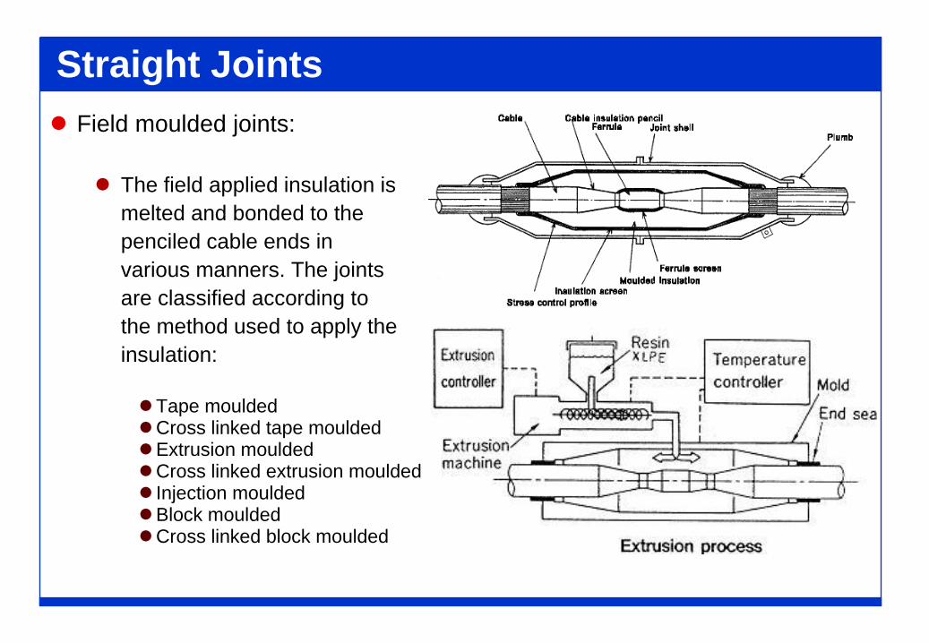
Straight Joints Field moulded joints:
The field applied insulation ismelted and bonded to thepenciled cable ends invarious manners. The jointsare classified according tothe method used to apply theinsulation:
Tape mouldedCross linked tape mouldedExtrusion mouldedCross linked extrusion moulded Injection mouldedBlock mouldedCross linked block moulded
Straight Joints
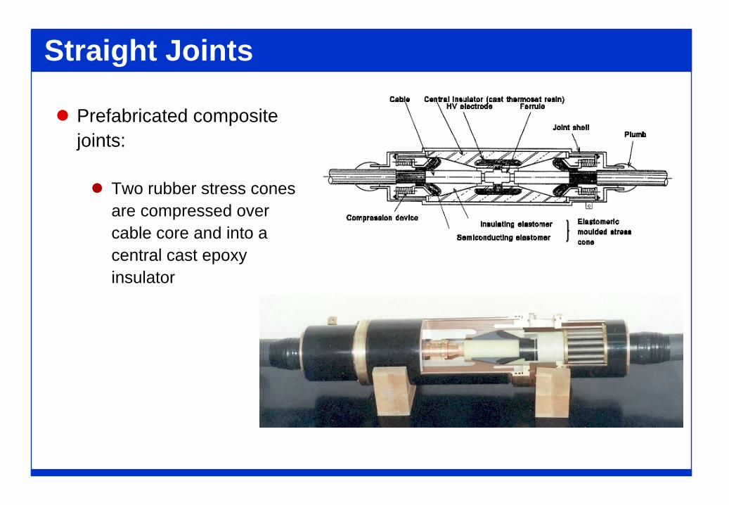
Prefabricated compositejoints:
Two rubber stress conesare compressed overcable core and into acentral cast epoxyinsulator
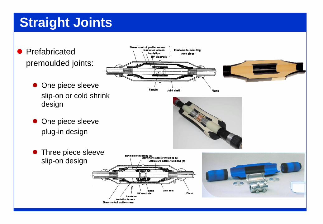
Straight Joints
Prefabricatedpremoulded joints:
One piece sleeveslip-on or cold shrink design
One piece sleeveplug-in design
Three piece sleeve slip-on design
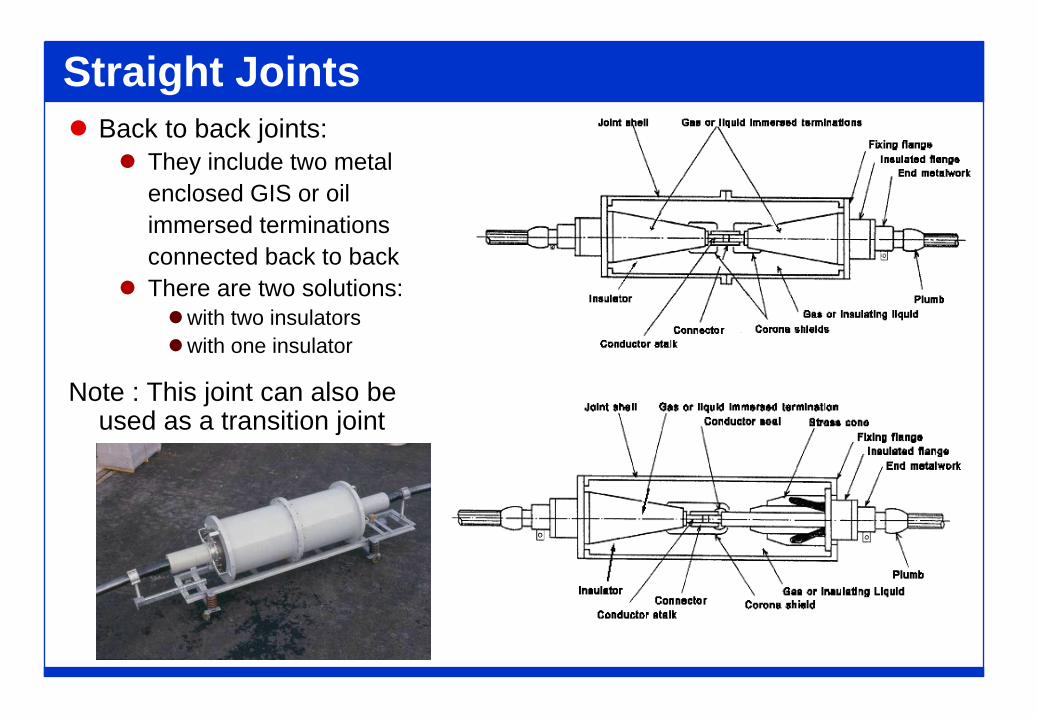
Straight Joints Back to back joints:
They include two metalenclosed GIS or oilimmersed terminationsconnected back to back
There are two solutions:with two insulatorswith one insulator
Note : This joint can also be used as a transition joint
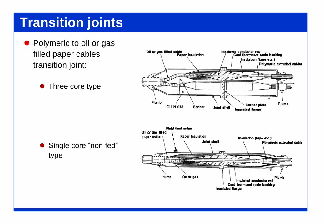
Transition joints Polymeric to oil or gas
filled paper cablestransition joint:
Three core type
Single core “non fed”
type
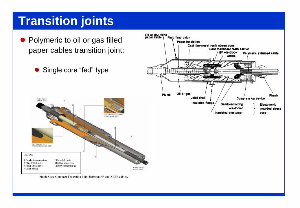
Transition joints Polymeric to oil or gas filled
paper cables transition joint:
Single core “fed” type
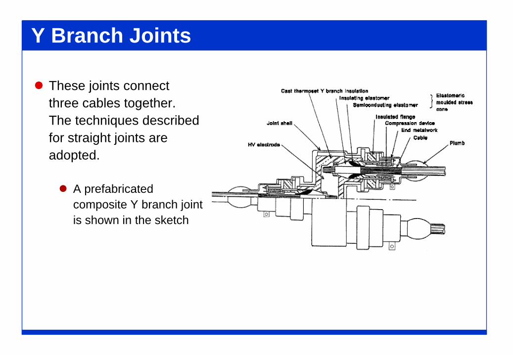
Y Branch Joints
These joints connectthree cables together.The techniques describedfor straight joints areadopted.
A prefabricatedcomposite Y branch jointis shown in the sketch
Termination Types Metal enclosed GIS terminations: connecting the cable to a GIS
Oil immersed transformer termination: connecting the cable toan oil immersed transformer bushing
Outdoor/Indoor termination: connecting the cable to anoverhead line either directly exposed to full climatic conditions(outdoor) either to a protected environment (indoor)
Temporary termination: connecting the cable to an overheadline for a limited time
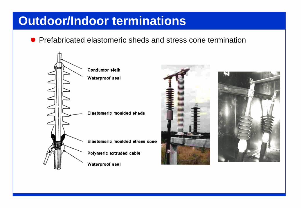
Outdoor/Indoor terminations Prefabricated elastomeric sheds and stress cone termination
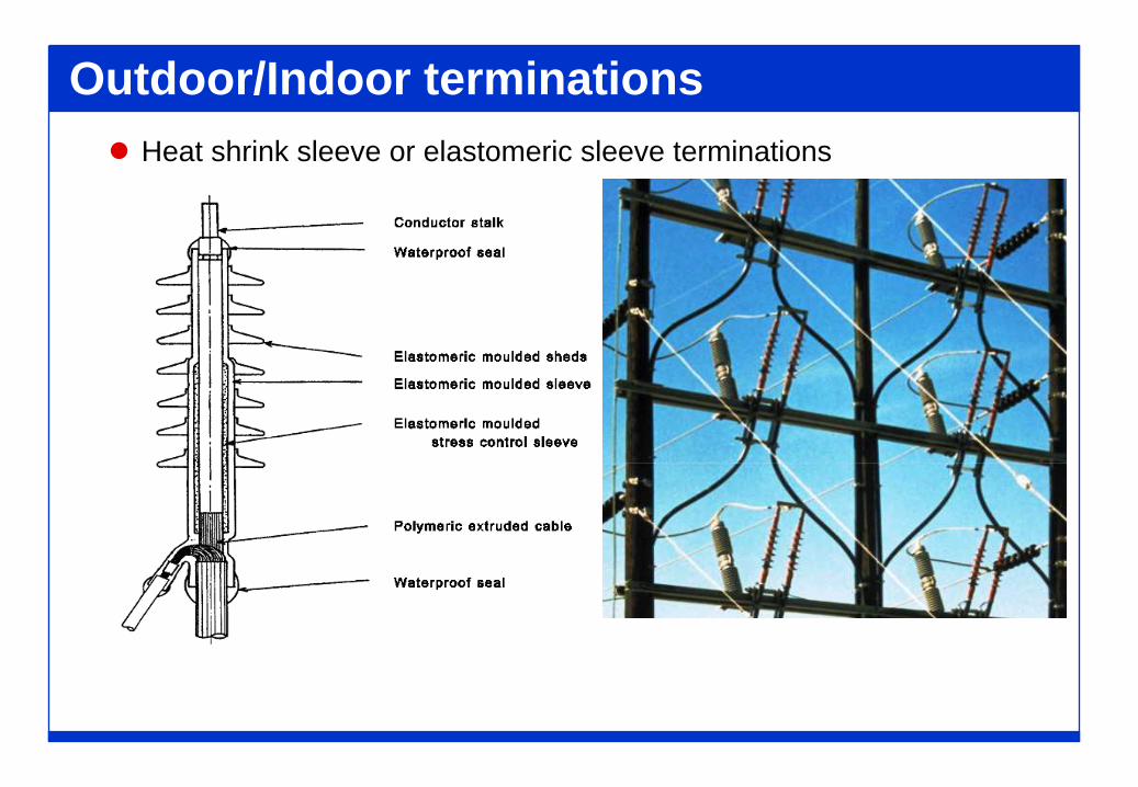
Outdoor/Indoor terminations Heat shrink sleeve or elastomeric sleeve terminations
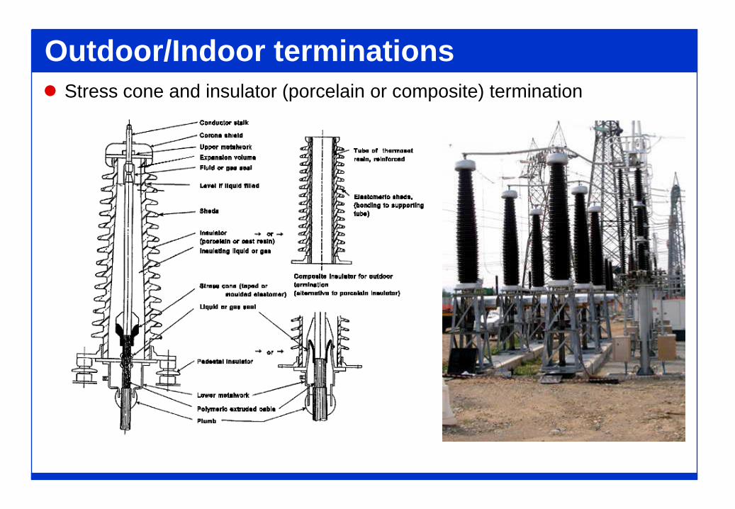
Outdoor/Indoor terminations Stress cone and insulator (porcelain or composite) termination
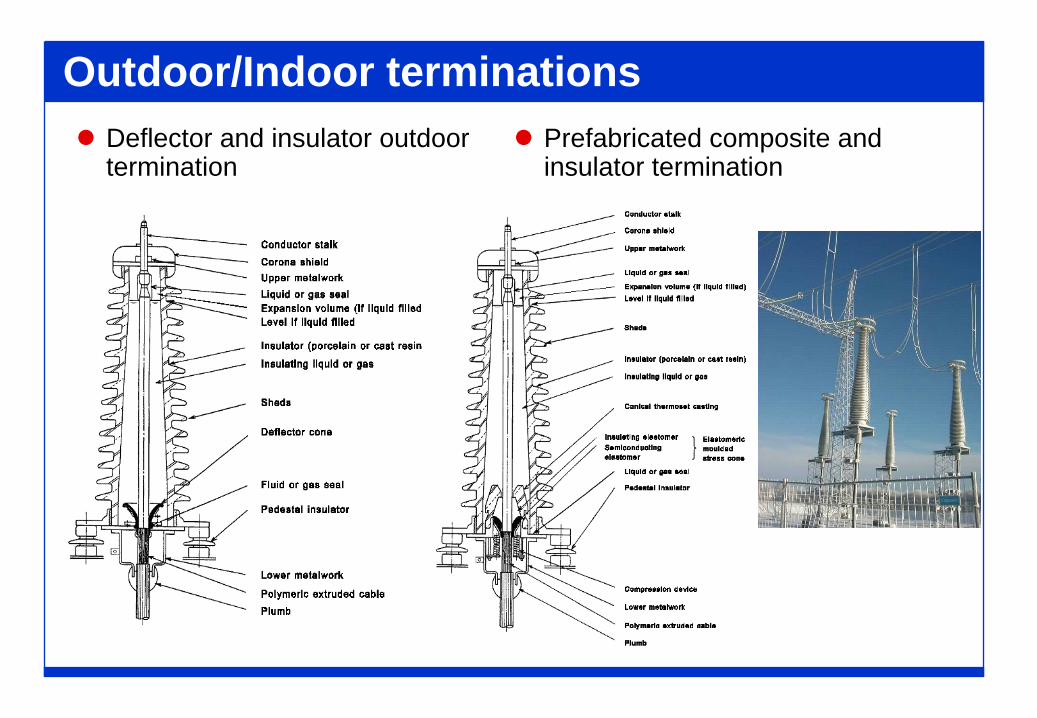
Outdoor/Indoor terminations Deflector and insulator outdoor
termination Prefabricated composite and
insulator termination
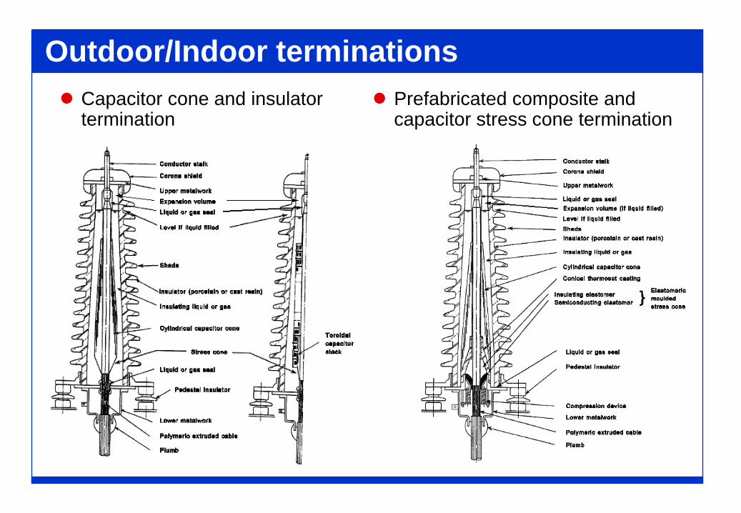
Outdoor/Indoor terminations Capacitor cone and insulator
termination Prefabricated composite and
capacitor stress cone termination
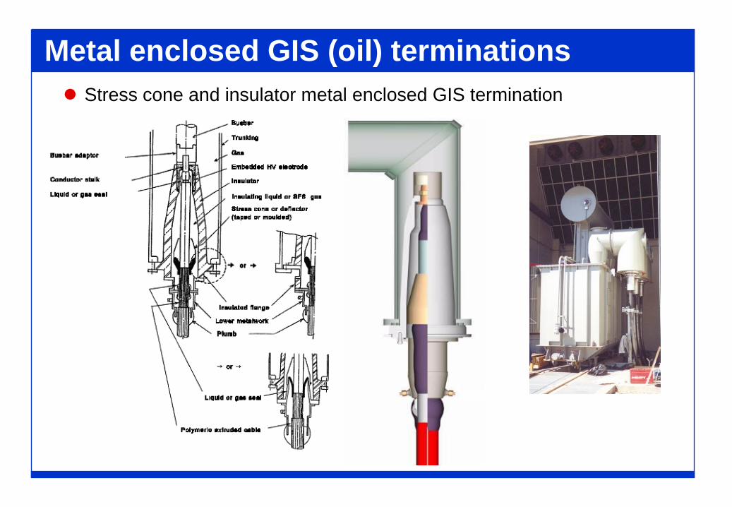
Metal enclosed GIS (oil) terminations Stress cone and insulator metal enclosed GIS termination
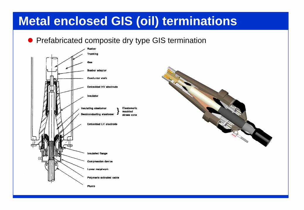
Metal enclosed GIS (oil) terminations Prefabricated composite dry type GIS termination
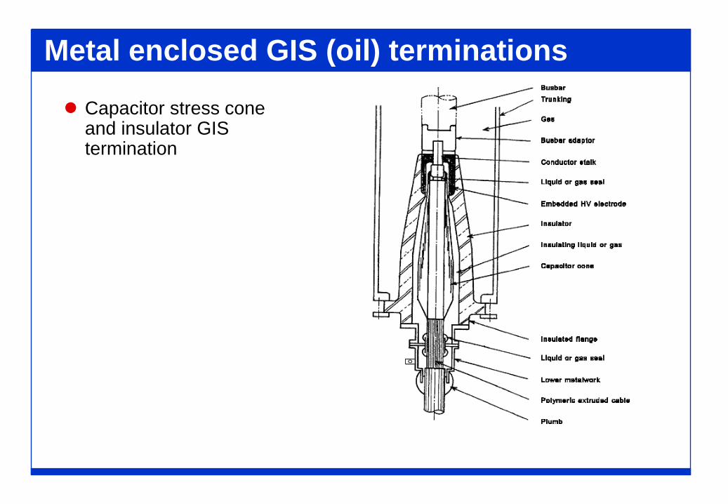
Metal enclosed GIS (oil) terminations
Capacitor stress cone and insulator GIS termination
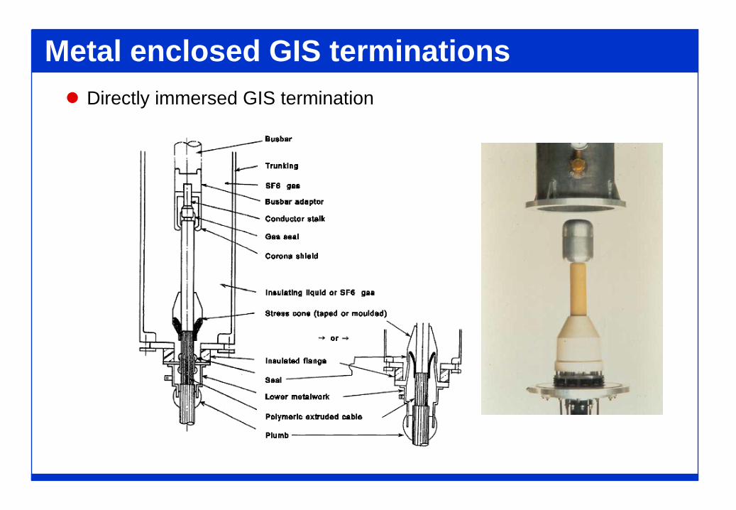
Metal enclosed GIS terminations Directly immersed GIS termination
ACCESSORIESMAIN COMPONENTS
(Part 2)
Conductor connector
Conductor connection functions:
The connector must be able to carry the same current as the cable conductor
The connection must be capable of withstanding the cable longitudinal thermomechanical forces
The connection must be compatible with other accessory parts
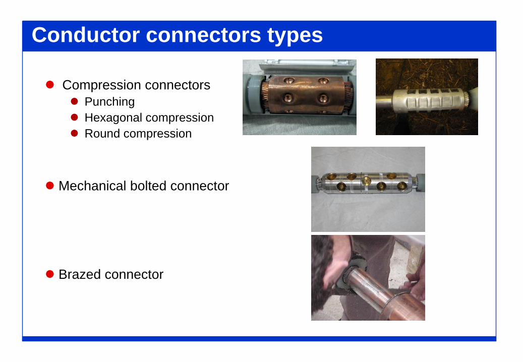
Conductor connectors types
Compression connectors Punching Hexagonal compression Round compression
Mechanical bolted connector
Brazed connector
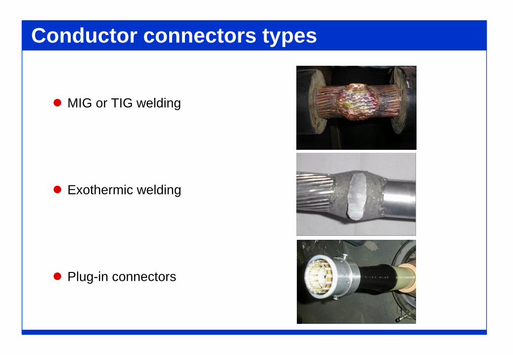
Conductor connectors types
MIG or TIG welding
Exothermic welding
Plug-in connectors
Sheath closures
Metallic sheath closures have the following functions:
To conduct the capacitive and short circuit currents of the cablecircuit
To seal the connection between the cable sheath and theaccessory end bell against moisture/water penetration
To withstand the sheath thermo-mechanical forces
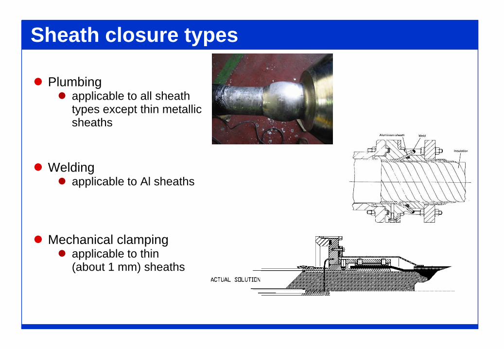
Sheath closure types
Plumbing applicable to all sheath
types except thin metallicsheaths
Welding applicable to Al sheaths
Mechanical clamping applicable to thin
(about 1 mm) sheaths
Joint anticorrosion protection
Joint anticorrosion protection function:
Protect the joint metal work from corrosion
Prevent water from entering into the joint
Electrically isolate from earth the metallic joint shell or wire shieldfor specially bonded cable circuits
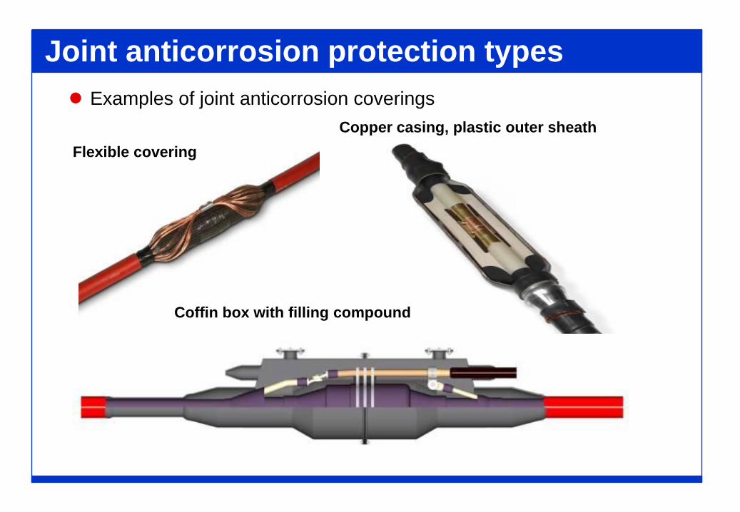
Copper casing, plastic outer sheath
Coffin box with filling compound
Flexible covering
Joint anticorrosion protection types Examples of joint anticorrosion coverings
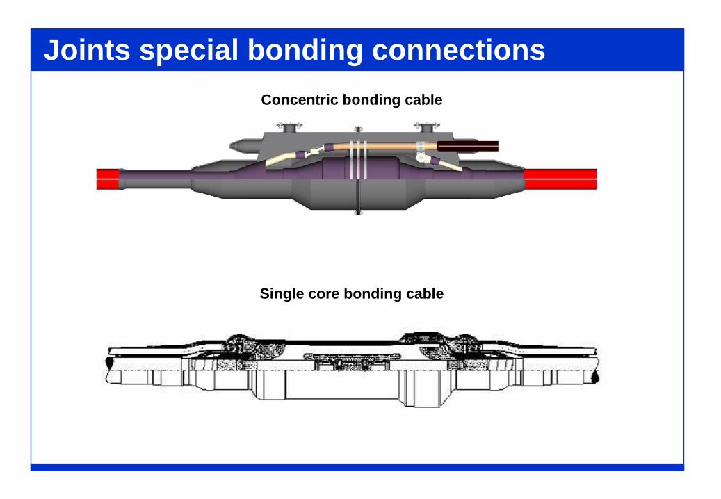
Joints special bonding connectionsConcentric bonding cable
Single core bonding cable
GUIDE TO THE SELECTION OF ACCESSORIES
Compatibility with the cable
Required information about the cable characteristics:
Number of cable cores
Cable construction details
Operating temperature of the cable conductor and sheath undercontinuous, overload and short circuit conditions
Compatibility with the type of cable insulation and semiconducting screens
Cable electrical stresses to be withstood by the accessory
Mechanical forces and movements generated by the cable on theaccessory
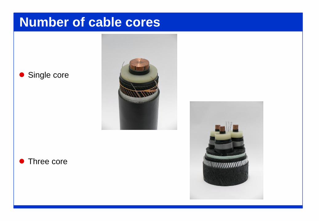
Number of cable cores
Single core
Three core
Cable construction details It is important that the correct size of accessory is selected to
suit the particular cable, so the following cable constructioninformation is required:
Conductor material, area and diameter and special features (i.e.water blocking or enameled wires)
Conductor screen diameter Insulation material, diameter and tolerances (including ovality and
eccentricity) Insulation screen diameter Screen wires, if any Longitudinal water blocking, if any Metallic barrier, if any Oversheath Armour, if any Special features (i.e. presence of optical fibre or pilot wires)
Compatibility with cable materials
Physical compatibility with the extruded cable insulation The cable insulation materials are: XLPE, LDPE, HDPE,EPR
Chemical compatibility The type of insulating liquid used in the accessory may affect the
properties of the cable insulation and screen material
Compatibility with the paper insulated cable In transition joints the fluid dielectric of the paper cable may come in
contact with the components of the extruded cable or of the accessory
Cable mechanical forces
The following mechanical strains generated by the cable on theaccessory are dependent on the cable construction:
Insulation retraction (shrink back) Insulation radial thermal expansion Oversheath retraction
The following forces are dependent on the cable construction,current loading, method and type of cable constraint:
Conductor thermomechanical thrust and retraction Sheath thermomechanical thrust and retraction

Compatibility with cable performance
Required information about the cable performance: Circuit performance parameters
Rated voltageCurrent ratingOverload conditionsShort circuit ratingBasic impulse level
Circuit life required Typically from 20 to 40 years
Sheath bonding requirementsType of cable bonding schemeType and size of bonding leads
Earth fault requirementsScreen connections able to bring short circuit current
Compatibility with cable system
Required information about the cable system design andoperating conditions:
Type of cable installation
Standard dimensions of cable terminations
Type of accessory installation environment
Jointing limitations in restricted installation location
Mechanical forces applied to the accessory
Climatic and environmental conditions
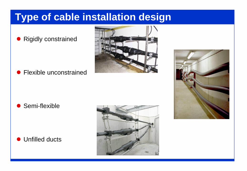
Type of cable installation design
Rigidly constrained
Flexible unconstrained
Semi-flexible
Unfilled ducts
Standard dimensions for terminations For GIS and transformer terminations:
Harmonization of cable termination dimensions with the design of themetalclad switgear are given in IEC 62271-209 (for GIS terminations) andin Cenelec EN 50299 (for transformer terminations)
For outdoor and indoor terminations:
Harmonization with the overall height of the busbar connection andbottom metalwork fixing arrangement is required
For outdoor terminations:
Creepage distance to accommodate the required pollution level (according to IEC 60815)
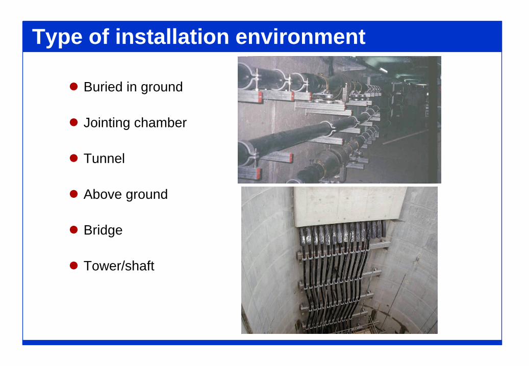
Type of installation environment
Buried in ground
Jointing chamber
Tunnel
Above ground
Bridge
Tower/shaft
Jointing limitations
Jointing limitations in restricted installation location:
Space limitations
Time limitationsRoad traffic influencesOutage duration in case of repair
Tolerance limitation of assembly personnelExtremes of temperatureExtremes of humiditySevere vibrationsHigh noise Induced voltage
External mechanical forces
Mechanical forces applied to the accessory due to the externalenvironment:
Thermomechanical forces Earthquake Vibration Off-going busbar at terminations Wind loading on busbars at outdoor terminations Ice loading on busbars at outdoor terminations Short circuit loading on busbars at terminations GIS gas pressure Angle of installation of outdoor/indoor terminations Hydraulic or pneumatic pressure forces at transition joints
Climatic conditions
Accessories are sometime required to operate in severe climaticconditions that can affect their performance (mainly theelectrical strength of outdoor insulator surface). Critical factors to be considered are:
Altitude Air pollution Precipitation Salt fog Moisture condensation Temperature

TESTS ON ACCESSORIES

Development tests
These tests are carried out by themanufacturers at the development stage ofthe accessory and include:
Electrical: AC and Impulse breakdowntests, short circuit test onconductor connector and sheathconnections, pollution test onoutdoor insulators
Mechanical: thrust test and pressure teston insulators
Thermal/thermo-mechanical tests
Routine tests
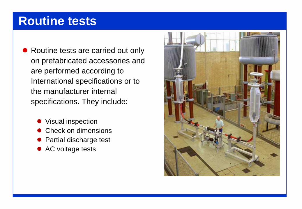
Routine tests are carried out onlyon prefabricated accessories andare performed according toInternational specifications or tothe manufacturer internalspecifications. They include:
Visual inspection Check on dimensions Partial discharge test AC voltage tests
Type tests
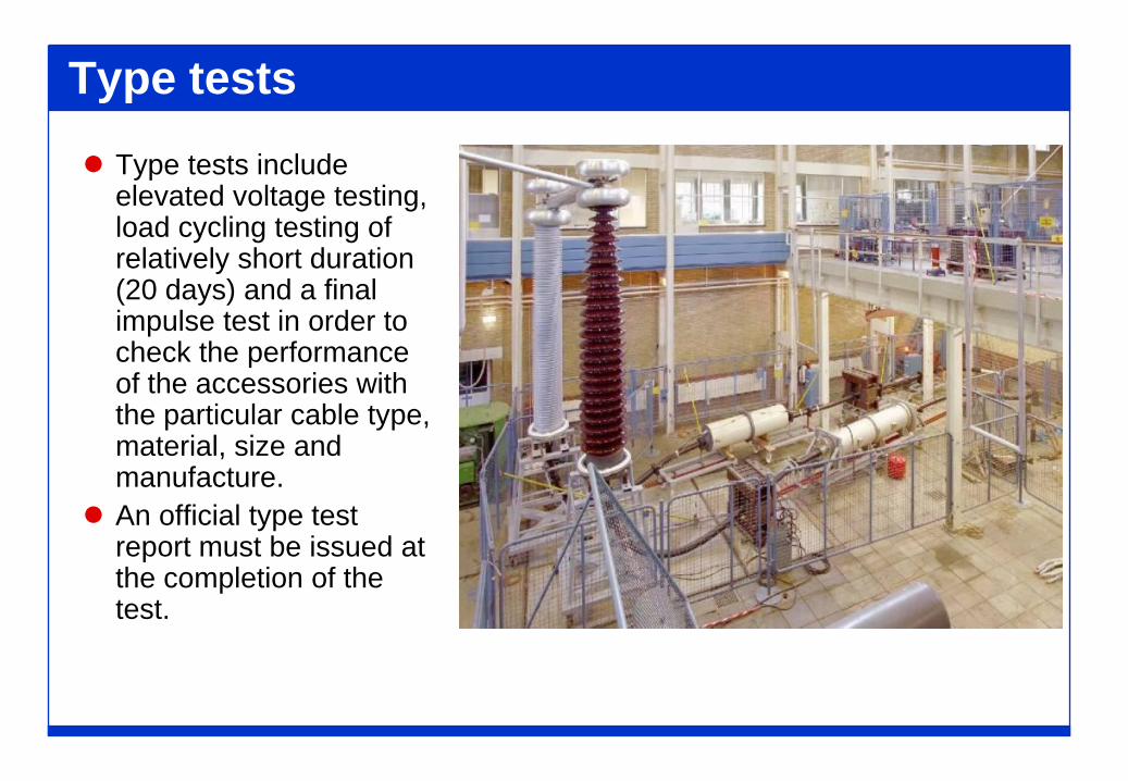
Type tests include elevated voltage testing, load cycling testing of relatively short duration (20 days) and a final impulse test in order to check the performance of the accessories with the particular cable type, material, size and manufacture.
An official type test report must be issued at the completion of the test.
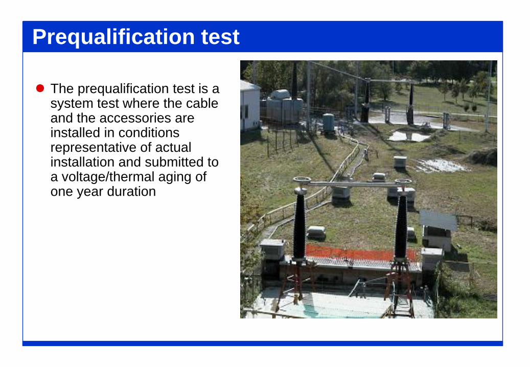
Prequalification test
The prequalification test is a system test where the cable and the accessories are installed in conditions representative of actual installation and submitted to a voltage/thermal aging of one year duration
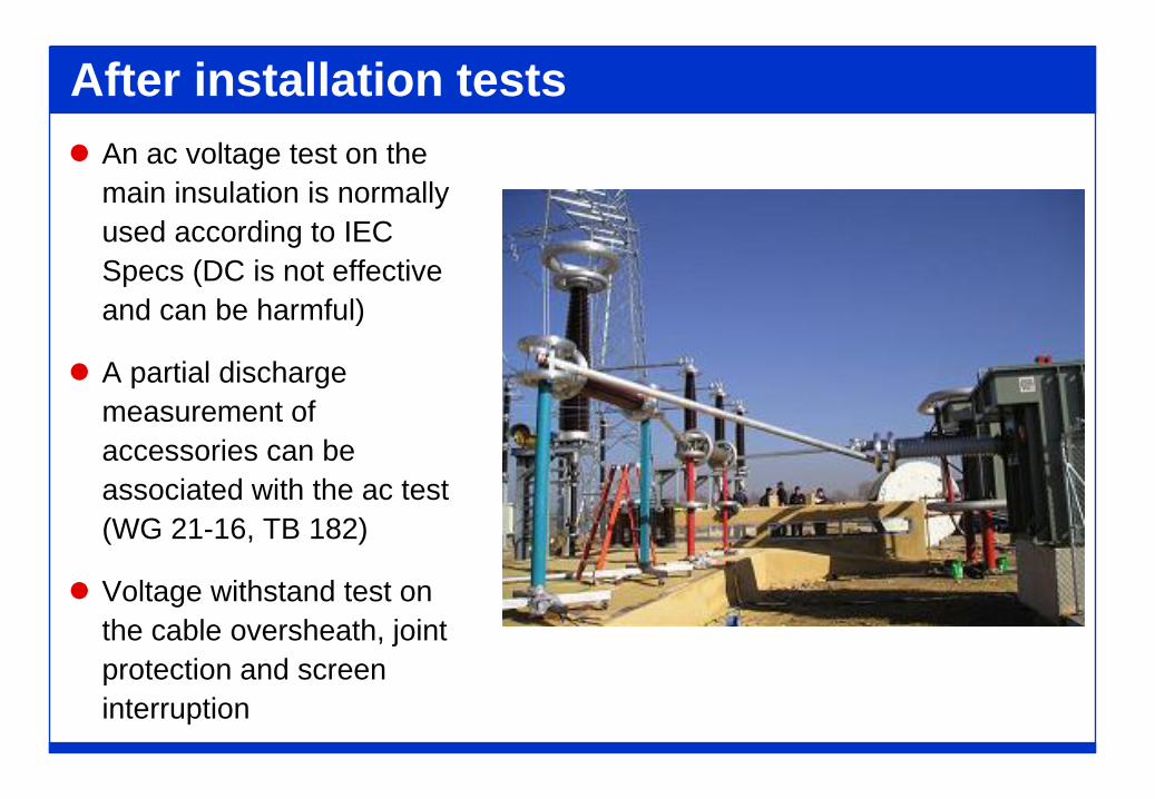
After installation tests An ac voltage test on the
main insulation is normallyused according to IEC Specs (DC is not effectiveand can be harmful)
A partial dischargemeasurement of accessories can beassociated with the ac test (WG 21-16, TB 182)
Voltage withstand test onthe cable oversheath, jointprotection and screeninterruption

ACCESSORIES INSTALLATION
Quality assurance considerations
Quality Assurance approval for Installation existence of an approved Quality Assurance System to an
internationally recognised standard.
Quality Plan including for each project: the time schedule the specific requirements for execution and traceability
If purchasing separately, the User is advised to ensure that thequality systems of cable manufacturer, accessorymanufacturer, and installer are compatible.
Quality plan
A Quality plan is required for each project including:
Project time schedule
Requirements for:
suitably qualified personnel trainingon-site storage of components and accessories tools testing equipment constructing materialsassembly instructionspreparation of the jointing environment records of the assembly works
Training of personnel
When selecting the designs of accessories the User should ensurethat training courses are available for the jointing and supervisorypersonnel.
It is strongly advised that personnel receive training on theparticular designs of accessories and cable.
Training of assembly personnel
Examples of the elements of a training course for assembly personnel are:
General training at specific system voltages with the standard range of accessories required by the User
Repeat training after a defined period for those personnel who have completed general training
Specified training on a new accessory or cable design for those personnel who have completed general training.
Assessment of proficiency of training At the end of the training course the proficiency of the assembly
personnel is normally assessed, for example, by a verbal or written examination, by a practical test and preferably by performing on the assembled accessories an electrical partial
discharge test and voltage withstand test.
Proficiency is recognised at the completion of training by the issue of a certificate, which should be checked by the User as part of the quality plan for a specific project.
In many instances a kit of general jointing tools and a set of general assembly instructions is also issued to the personnel following satisfactory completion of training.
Assembly instructions
The accessory manufacturer is required to supply a complete set of assembly instructions together with drawings of the particular accessory. list of specified assembly tools specified consumable materials health and safety precautions recommendations for preparation of the assembly environment.
It is important that the User studies the instructions before work begins to ensure: that the workplace is correctly prepared that all the tools and consumable materials are available.
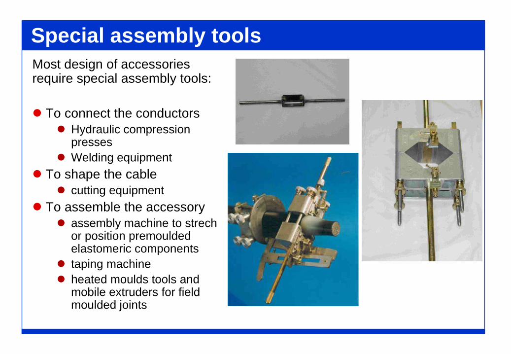
Special assembly toolsMost design of accessories require special assembly tools:
To connect the conductors Hydraulic compression
presses Welding equipment
To shape the cable cutting equipment
To assemble the accessory assembly machine to strech
or position premoulded elastomeric components
taping machine heated moulds tools and
mobile extruders for field moulded joints
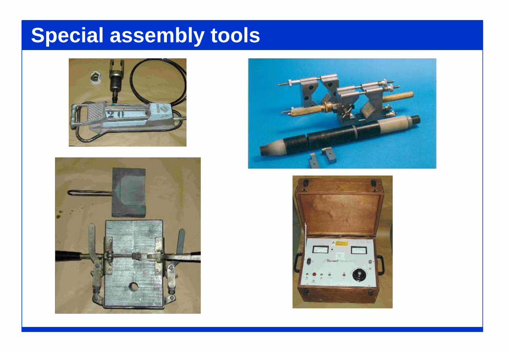
Special assembly tools
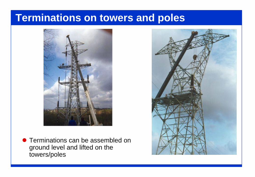
Terminations on towers and poles
Terminations can be assembled on ground level and lifted on the towers/poles
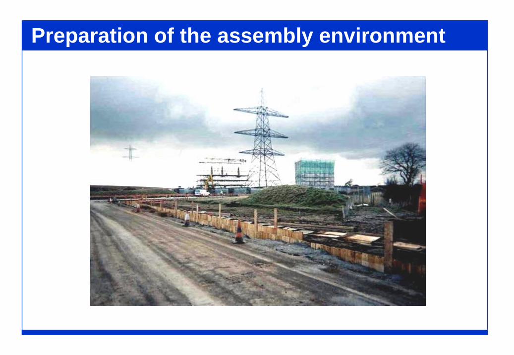
Preparation of the assembly environment
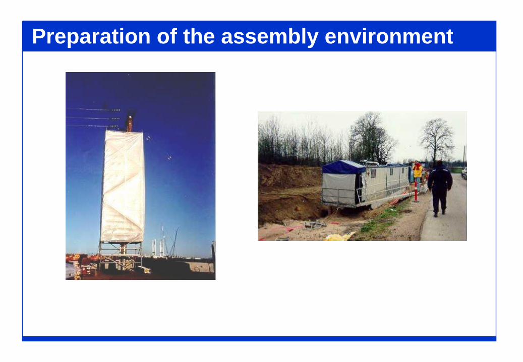
Preparation of the assembly environment
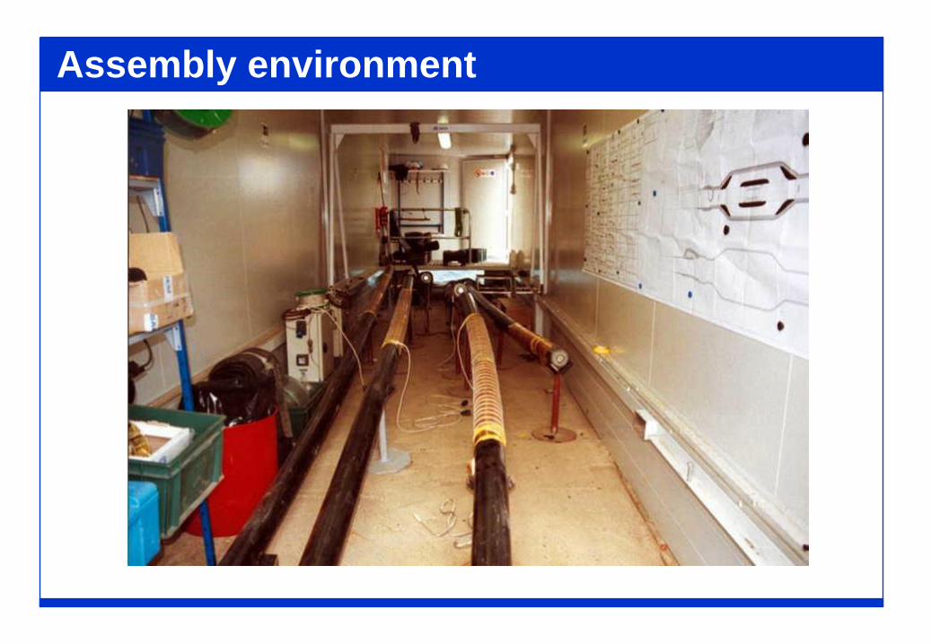
Assembly environment
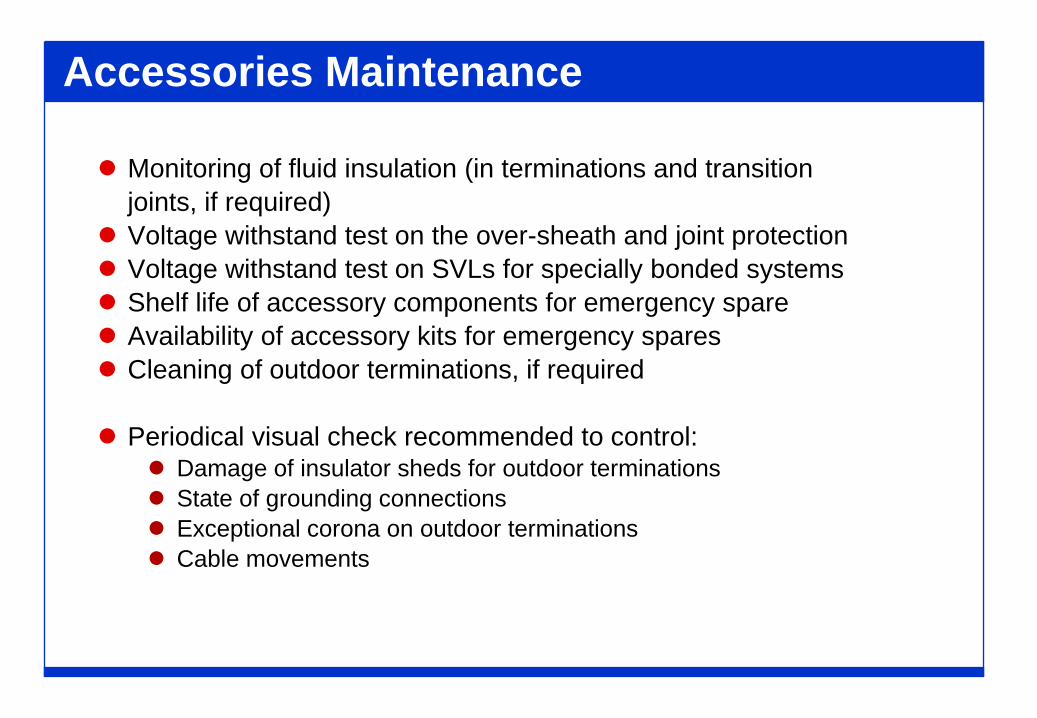
Accessories Maintenance
Monitoring of fluid insulation (in terminations and transitionjoints, if required)
Voltage withstand test on the over-sheath and joint protection Voltage withstand test on SVLs for specially bonded systems Shelf life of accessory components for emergency spare Availability of accessory kits for emergency spares Cleaning of outdoor terminations, if required
Periodical visual check recommended to control: Damage of insulator sheds for outdoor terminations State of grounding connections Exceptional corona on outdoor terminations Cable movements