Embed Size (px)
Citation preview
AccurateStereophotogrammetry
John MorrisElectrical and Computer Engineering/Computer Science,The University of Auckland
Iolanthe on the Hauraki Gulf
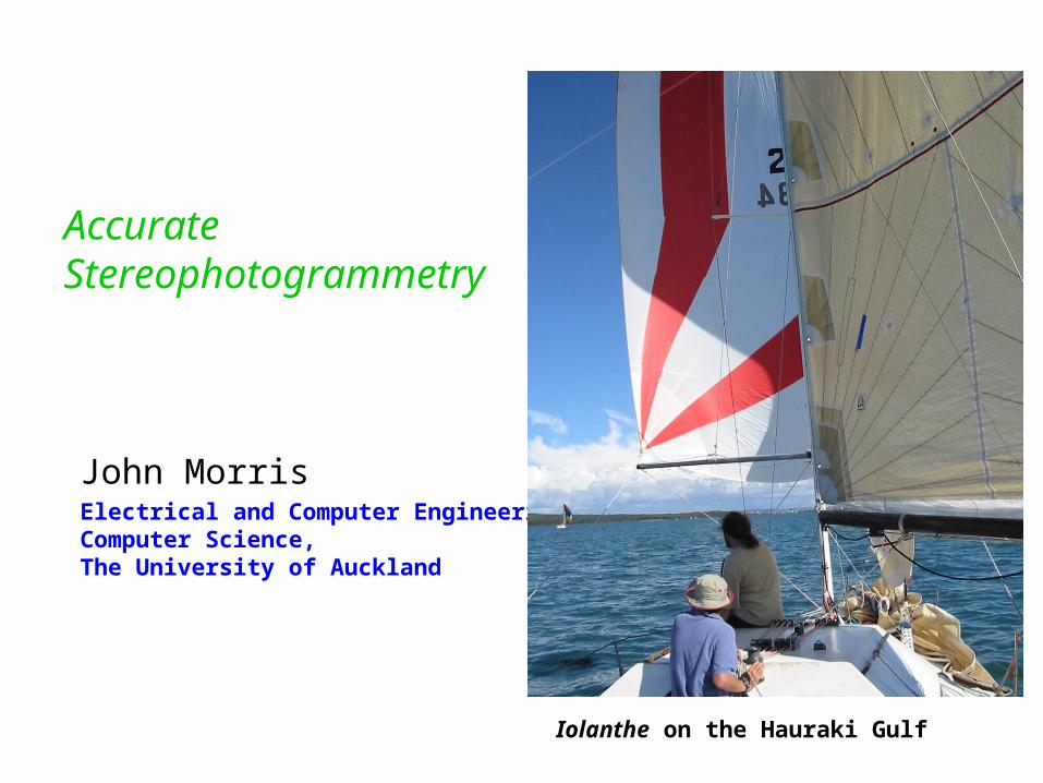
What is Stereo PhotogrammetryF?Pairs of images giving different views of the scene
can be used to compute a depth (disparity) map
Key task – CorrespondenceLocate matching regions in both images
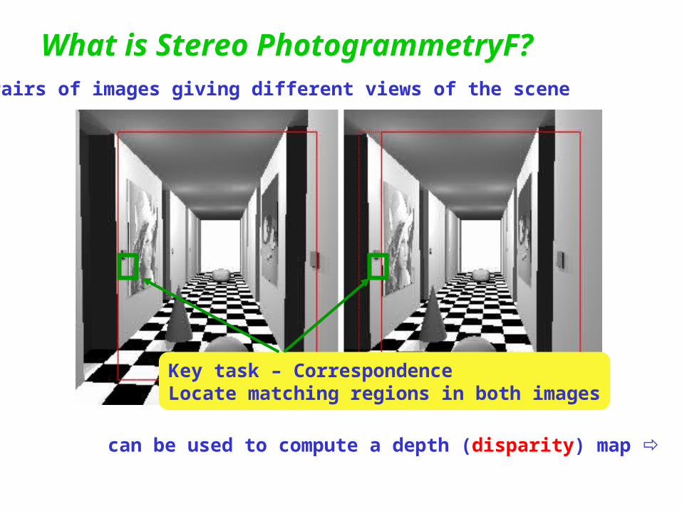
Depth Maps
Computed: Census Ground Truth Computed: Pixel-to-Pixel
Which is the better algorithm?
Vision Research tends to be rather visual !Tendency to publish images `proving’ efficacy, efficiency, etc
Motivation
Stereophotogrammetry started with a focus on accuracyUsed to produce accurate maps from aerial
photographyRelied on
Large, expensive, mechanical ‘machines’ to align images and measure disparities
High resolution photographic film in precise cameras
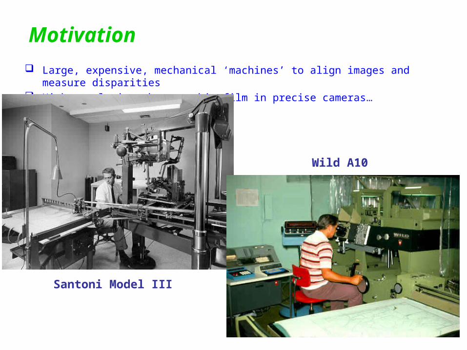
Motivation Large, expensive, mechanical ‘machines’ to align images and measure disparities High resolution photographic film in precise cameras…
Santoni Model III
Wild A10
Motivation
then .. Along came digital cameras and computers Low resolution ‘toy’ applications became the focus!Web cameras
cheap and stream low resolution images into a machine
Potential for tracking objects limited accuracy real-time environment mapping
All you need is a piece of wood, 2 webcams and some of Cliff’s time to interface two cameras to a single PC
Stereophotogrammetry
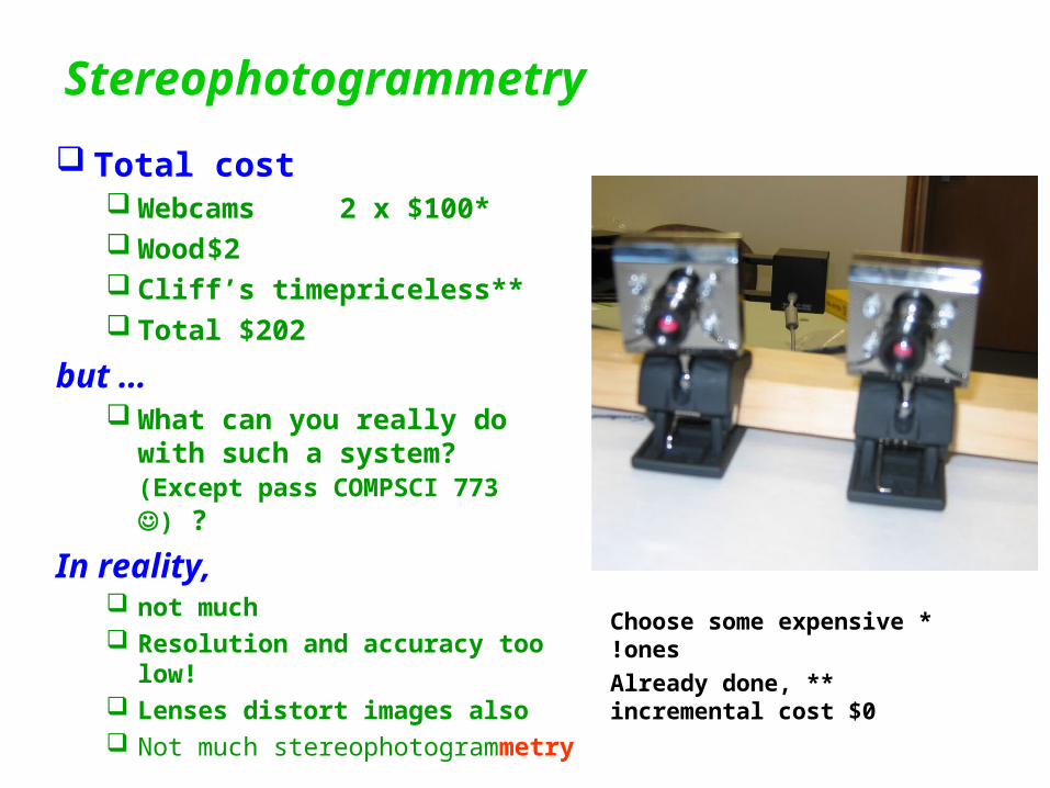
Total cost Webcams 2 x $100* Wood $2 Cliff’s time priceless** Total $202
but … What can you really do with
such a system?(Except pass COMPSCI 773 ) ?
In reality, not much Resolution and accuracy too low! Lenses distort images also Not much stereophotogrammetry
*Choose some expensive ones!
**Already done, incremental cost $0
Stereophotogrammetry
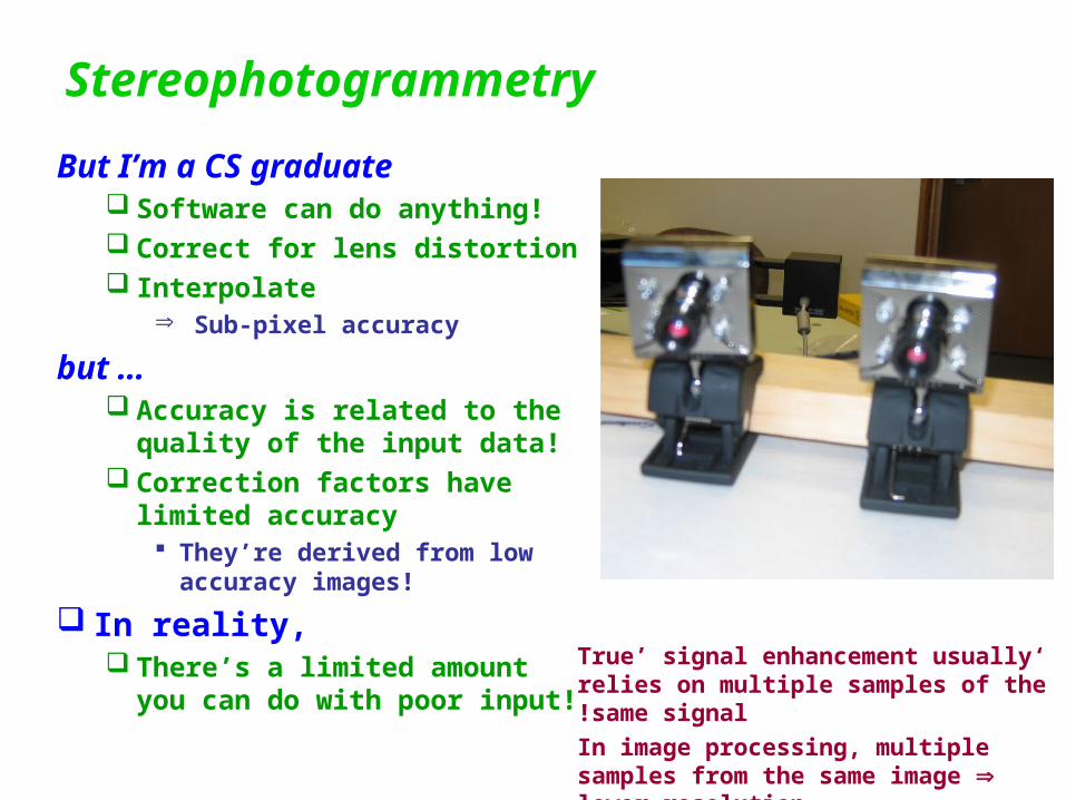
But I’m a CS graduate Software can do anything! Correct for lens distortion Interpolate
Sub-pixel accuracy
but … Accuracy is related to the
quality of the input data! Correction factors have limited
accuracy They’re derived from low
accuracy images!
In reality, There’s a limited amount you
can do with poor input!
‘True’ signal enhancement usually relies on multiple samples of the same signal!
In image processing, multiple samples from the same image lower resolution
Need for accuracy
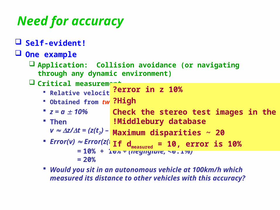
Self-evident! One example
Application: Collision avoidance (or navigating through any dynamic environment)
Critical measurement Relative velocity Obtained from two scene measurements
z = a 10% Then
v z/t = (z(t2) – z(t1)) / (t2 – t1 )
Error(v) Error(z(t1)) + Error(z(t2)) + Error(t1) + Error(t2) = 10% + 10% + (negligible, <0.1%) = 20%
Would you sit in an autonomous vehicle at 100km/h which measured its distance to other vehicles with this accuracy?
10% error in z?
High?
Check the stereo test images in the Middlebury database!
Maximum disparities ~ 20
If dmeasured = 10, error is 10%
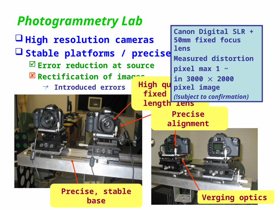
Photogrammetry Lab High resolution cameras Stable platforms / precise alignment
Error reduction at source Rectification of images
Introduced errors
Precise alignment
Precise, stable base
High quality, fixed focal length lens
Verging optics
Canon Digital SLR + 50mm fixed focus lens
Measured distortion
~1 pixel max
in 3000 2000 pixel image)subject to confirmation(!
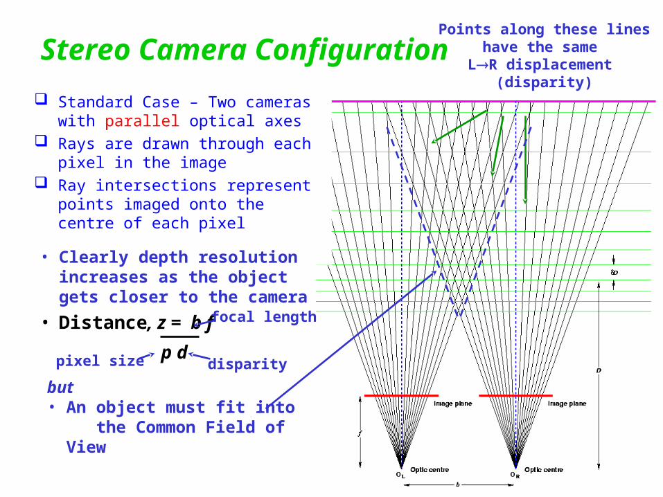
Stereo Camera Configuration
Standard Case – Two cameras with parallel optical axes
Rays are drawn through each pixel in the image
Ray intersections represent points imaged onto the centre of each pixel
Points along these lineshave the same
LR displacement (disparity)
but• An object must fit into
the Common Field of View
• Clearly depth resolution increases as the object gets closer to the camera
• Distance, z = b f
p ddisparity
focal length
pixel size
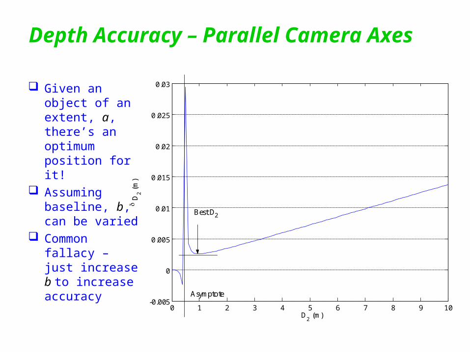
Depth Accuracy – Parallel Camera Axes
0 1 2 3 4 5 6 7 8 9 10-0.005
0
0.005
0.01
0.015
0.02
0.025
0.03
D2 (m)
D
2 (
m)
Asymptote
Best D2
Given an object of an extent, a, there’s an optimum position for it!
Assuming baseline, b, can be varied
Common fallacy – just increase b to increase accuracy
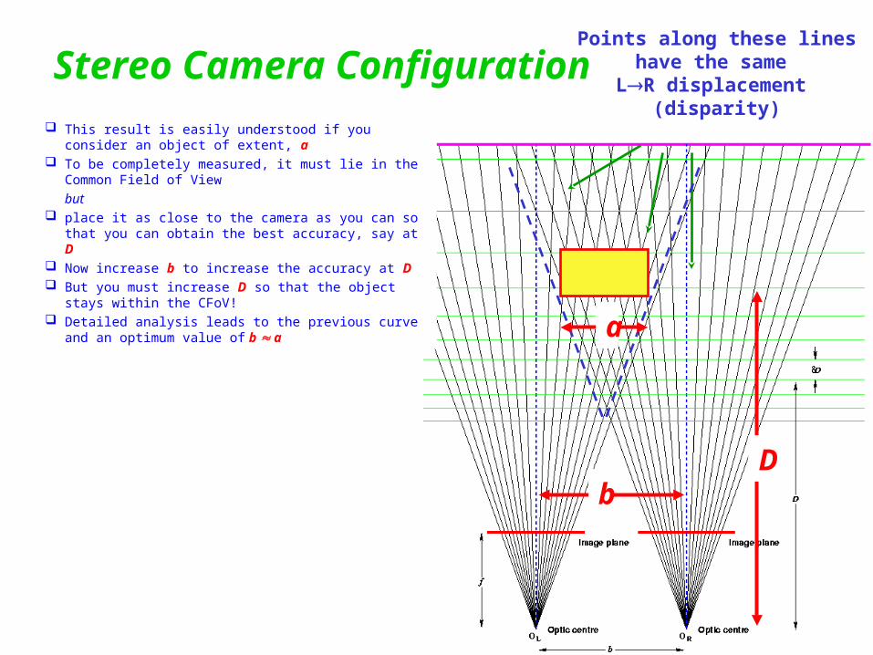
Stereo Camera Configuration This result is easily understood if you consider an
object of extent, a To be completely measured, it must lie in the Common
Field of View but place it as close to the camera as you can so that you
can obtain the best accuracy, say at D Now increase b to increase the accuracy at D But you must increase D so that the object stays within
the CFoV! Detailed analysis leads to the previous curve and an
optimum value of b a
Points along these lineshave the same
LR displacement (disparity)
a
bD
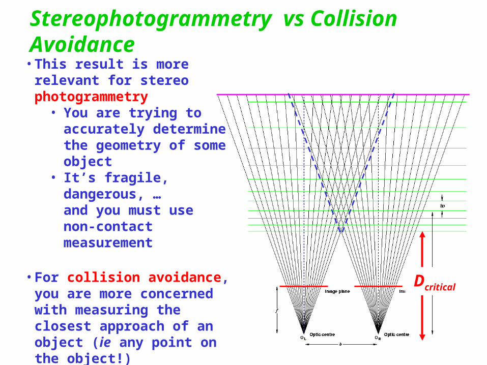
Stereophotogrammetry vs Collision Avoidance
• This result is more relevant for stereo photogrammetry
• You are trying to accurately determine the geometry of some object
• It’s fragile, dangerous, …and you must use non-contact measurement
• For collision avoidance, you are more concerned with measuring the closest approach of an object (ie any point on the object!)
you can increase the baseline so that the critical point stays within the CFoV
Dcritica
l
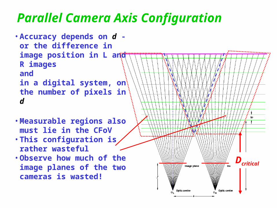
Parallel Camera Axis Configuration• Accuracy depends on d - or
the difference in image position in L and R imagesandin a digital system, on the number of pixels in d
• Measurable regions also must lie in the CFoV
• This configuration is rather wasteful
• Observe how much of the image planes of the two cameras is wasted! Dcritica
l
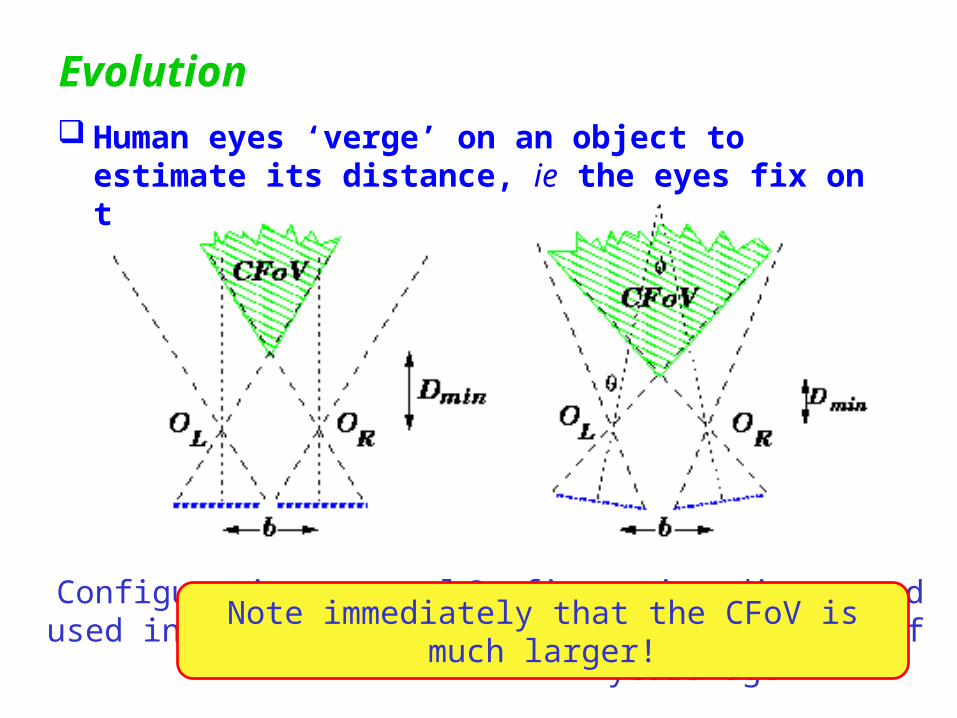
Evolution Human eyes ‘verge’ on an object to estimate its
distance, ie the eyes fix on the object in the field of view
Configuration commonlyused in stereo systems
Configuration discoveredby evolution millions of years
ago
Note immediately that the CFoV is much larger!
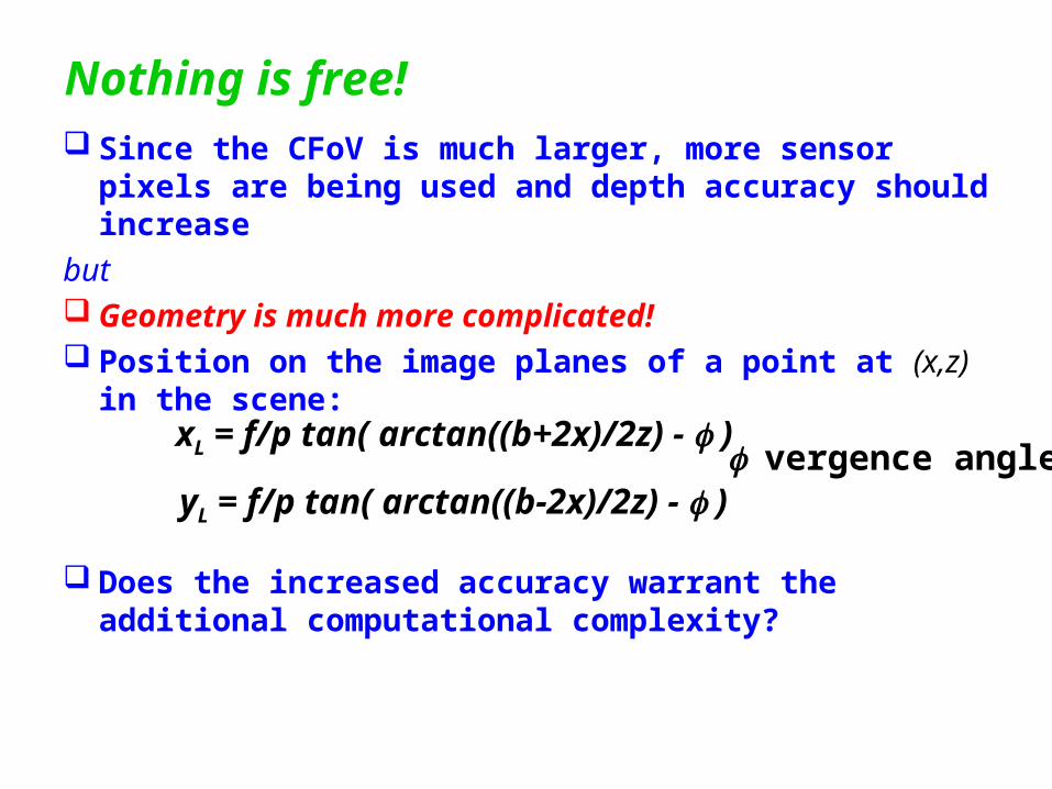
Nothing is free! Since the CFoV is much larger, more sensor pixels
are being used and depth accuracy should increase
but Geometry is much more complicated! Position on the image planes of a point at (x,z) in the
scene:
Does the increased accuracy warrant the additional computational complexity?
xL = f/p tan( arctan((b+2x)/2z) - )
yL = f/p tan( arctan((b-2x)/2z) - ) vergence angle
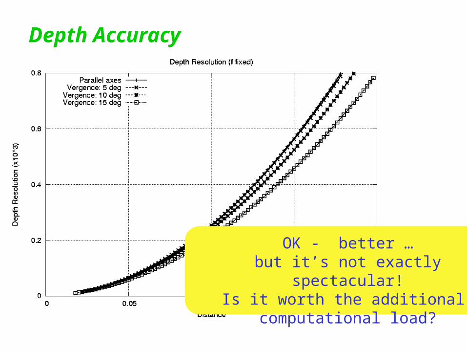
Depth Accuracy
OK - better …but it’s not exactly spectacular!
Is it worth the additional computational load?
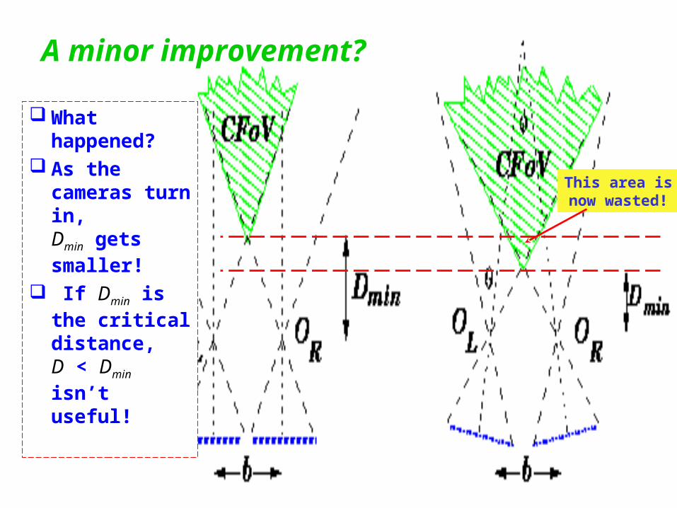
A minor improvement?
What happened?
As the cameras turn in,Dmin gets smaller!
If Dmin is the critical distance,D < Dmin isn’t useful!
This area isnow wasted!
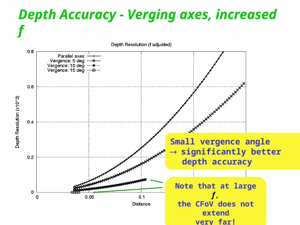
Depth Accuracy - Verging axes, increased f
Small vergence anglesignificantly better
depth accuracy
Note that at large f,the CFoV does not
extendvery far!
Increased focal length
Lenses with large f Thinner Fewer aberrations
Better images
Cheaper?
Alternatively, lower pixel resolution can be used to achieve better depth accuracy ...
Zero disparity matching
With verging axes,at the fixation point, scene points appear with zero disparity (in the same place on both L and R images)
If the fixation point is set at some sub-critical distance (eg an ‘early warning’ point), then matching algorithms can focus on a small range of disparities about 0
With verging axes, both +ve and -ve disparities appear
Potential for fast, high performance matching focussing on this region
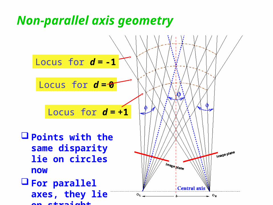
Locus for d = 0
Locus for d = +1
Locus for d = -1
Non-parallel axis geometry
Points with the same disparity lie on circles now
For parallel axes, they lie on straight lines
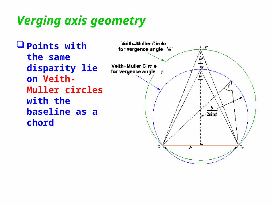
Verging axis geometry
Points with the same disparity lie on Veith-Muller circles with the baseline as a chord
Zero disparity matching (ZDM)
Using a fixation point in some critical regionintroduces the possibility of faster matching
It can alleviate the statistical factor reducing matching quality You search over a restricted disparity range Several ‘pyramidal’ matching techniques have been
proposed (and success claimed!) for conventional parallel geometries
These techniques could be adapted to ZDM
Care: It has no effect on the other three factors!
Correspondence
OK .. now we have an optimum geometry .. We just match up the images and Sit back and enjoy the ride as our car weaves its way
through the traffic! Unfortunately, digital computers aren’t as good as
human operators!eg the ones who produce maps from aerial photos!
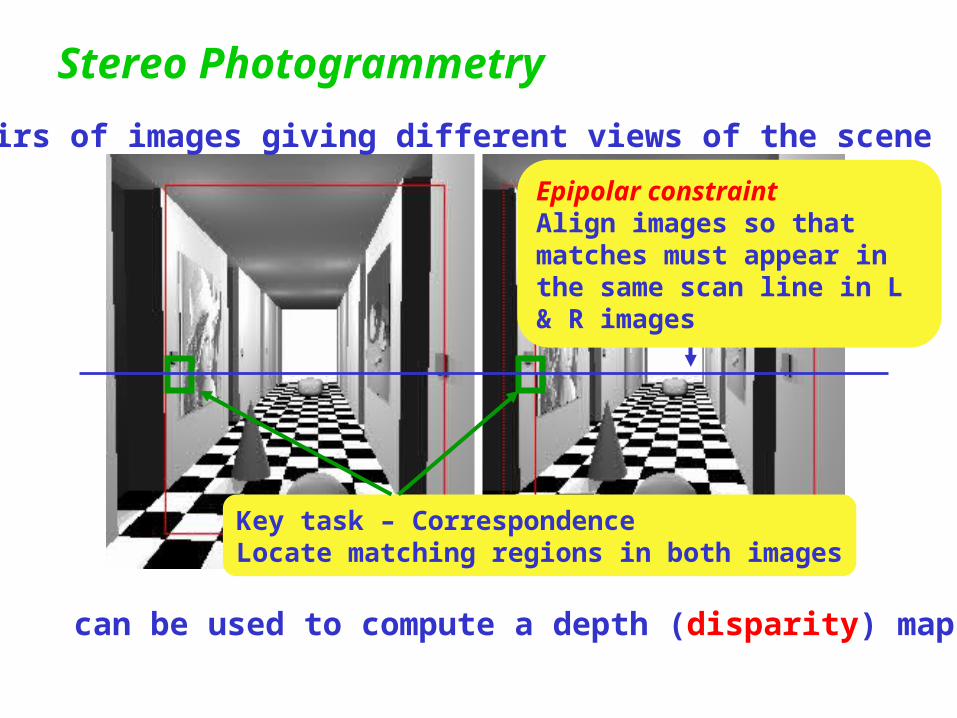
Stereo Photogrammetry
Pairs of images giving different views of the scene
can be used to compute a depth (disparity) map
Key task – CorrespondenceLocate matching regions in both images
Epipolar constraintAlign images so that matches must appear in the same scan line in L & R images
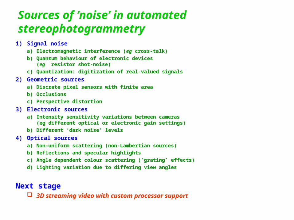
Sources of ‘noise’ in automated stereophotogrammetry
1) Signal noisea) Electromagnetic interference (eg cross-talk)
b) Quantum behaviour of electronic devices (eg resistor shot-noise)
c) Quantization: digitization of real-valued signals
2) Geometric sourcesa) Discrete pixel sensors with finite area
b) Occlusions
c) Perspective distortion
3) Electronic sourcesa) Intensity sensitivity variations between cameras
(eg different optical or electronic gain settings)
b) Different ‘dark noise’ levels
4) Optical sourcesa) Non-uniform scattering (non-Lambertian sources)
b) Reflections and specular highlights
c) Angle dependent colour scattering (‘grating’ effects)
d) Lighting variation due to differing view angles
Next stage 3D streaming video with custom processor support
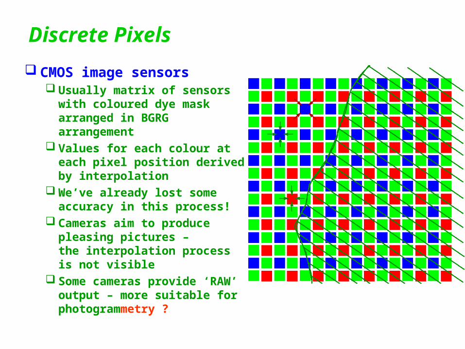
Discrete Pixels
CMOS image sensors Usually matrix of sensors with
coloured dye mask arranged in BGRG arrangement
Values for each colour at each pixel position derived by interpolation
We’ve already lost some accuracy in this process!
Cameras aim to produce pleasing pictures –the interpolation process is not visible
Some cameras provide ‘RAW’ output – more suitable for photogrammetry ?
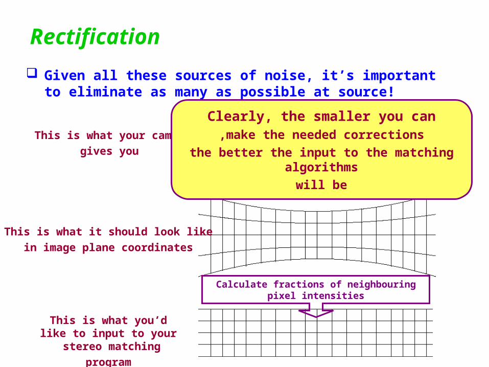
Rectification
Given all these sources of noise, it’s important to eliminate as many as possible at source!
This is what your camera
gives you
This is what it should look like
in image plane coordinates
This is what you’d like to input to your stereo matching
program
Calculate fractions of neighbouring pixel intensities
Real lens distortion
Clearly, the smaller you canmake the needed corrections,
the better the input to the matching algorithms
will be
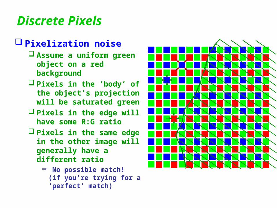
Discrete Pixels
Pixelization noise Assume a uniform green
object on a red background Pixels in the ‘body’ of the
object’s projection will be saturated green
Pixels in the edge will have some R:G ratio
Pixels in the same edge in the other image will generally have a different ratio
No possible match!(if you’re trying for a ‘perfect’ match)
Noise model
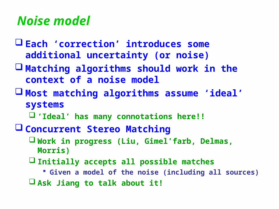
Each ‘correction’ introduces some additional uncertainty (or noise)
Matching algorithms should work in the context of a noise model
Most matching algorithms assume ‘ideal’ systems ‘Ideal’ has many connotations here!!
Concurrent Stereo Matching Work in progress (Liu, Gimel’farb, Delmas, Morris) Initially accepts all possible matches
Given a model of the noise (including all sources)
Ask Jiang to talk about it!
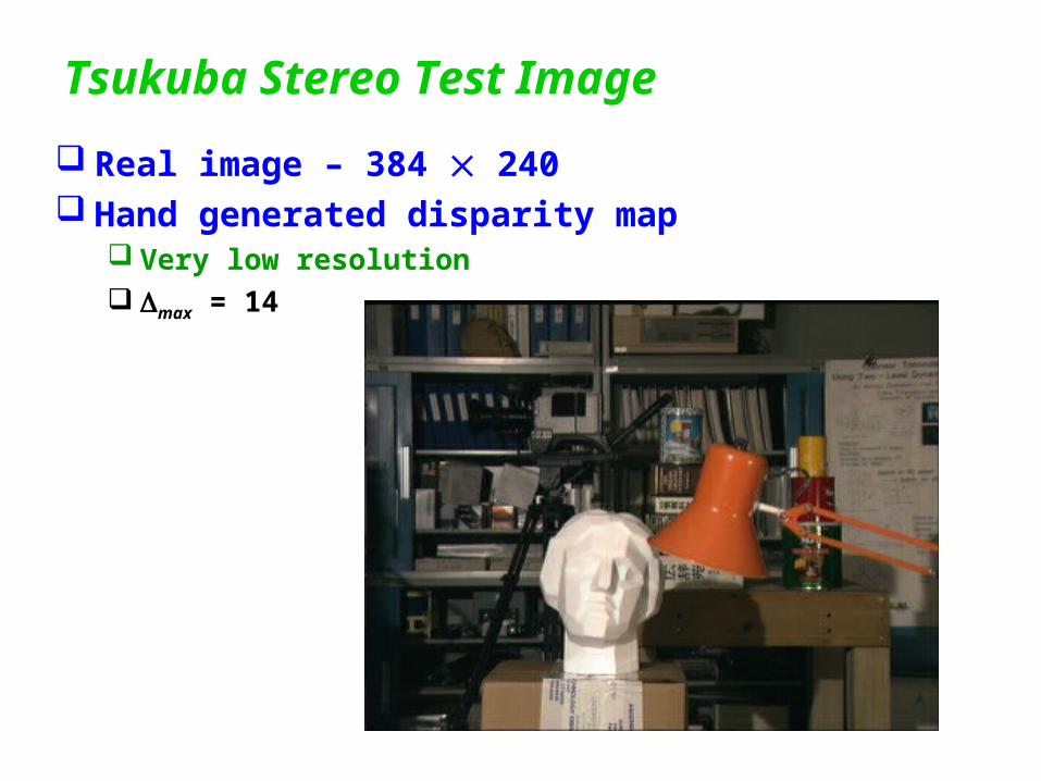
Tsukuba Stereo Test Image
Real image – 384 240 Hand generated disparity map
Very low resolution max = 14
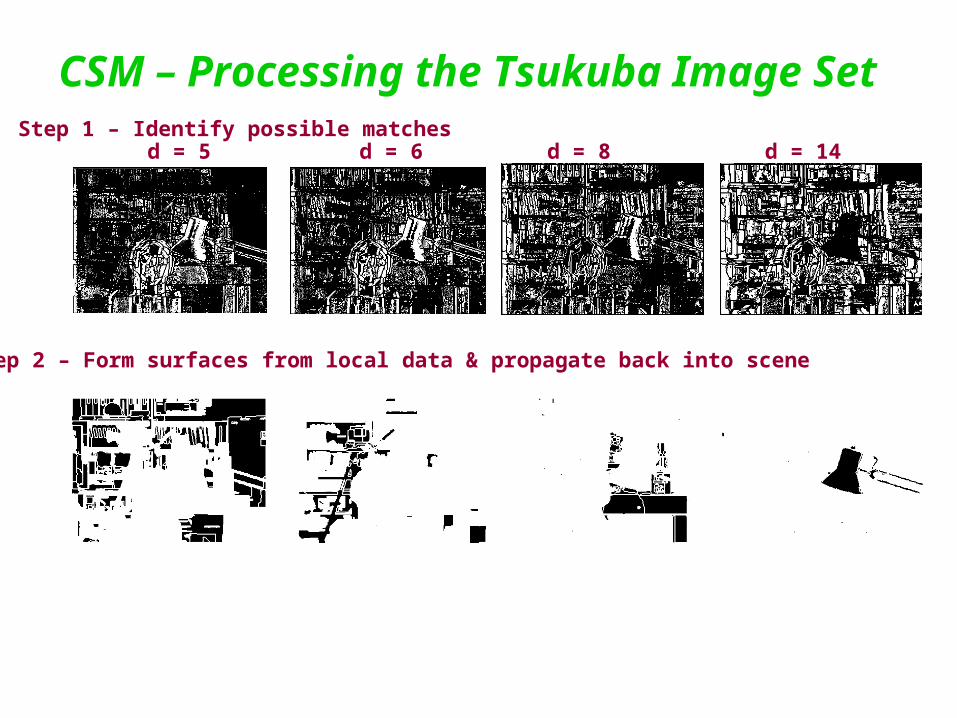
CSM – Processing the Tsukuba Image Set
Step 1 – Identify possible matchesd = 5 d = 14d = 8
Step 2 – Form surfaces from local data & propagate back into scene
d = 6
‘Competing’ techniques
Structure from motion Motion is equivalent to baseline of stereo system If accuracy of motion accuracy of baseline
Accuracy similar to parallel axis stereo
Generally relies on small movements to make matching problem tractable
Much smaller distance resolution
‘Competing’ techniques
Structured light Requires two devices (camera and projector) of comparable
resolution Slower
Unique labeling of pixels requires O(log n) images
Projector is a ‘real’ optical device too (with a real lens) Pattern edges are only sharp over a limited depth of field Efficient pixel labeling over a small depth range only Closing lens aperture to increase depth of field not an option
? Structured light ideas combined with stereo cameras Most effective combination?
‘Competing’ techniques
Laser Range Finder Produces depths ‘directly’ from time of flight or phase
difference measurements Single device
High precision scanning optics required Limits portability and robustness
Slow One point at a time
Very high potential accuracy Interferometer (/n) accuracy possible Time of flight systems limited by pulse length
• High accuracy still possible!
Affected by reflectivity of targets Sparse point clouds
Doesn’t need texture in the scene!
Future work
Real-time environment maps Very large numbers of trivial computations! High degree of parallelism (esp CSM algorithm)! Ideal application for custom hardware Limited accuracy system is feasible on 2005 FPGA hardware
Current work Efficient parallel algorithms
Concurrent Stereo Matching (EMMCVPR, Florida, Sept 2005)
Custom hardware implementation Goal: Depth maps at 30 fps video rates (3D movies!)
Efficient optical systems Manufacturable Robust
Next stage 3D streaming video with custom processor support