Embed Size (px)
Citation preview
www.renold.com
Tyreflex Couplings
www.renold.com
Superior Gear & Coupling Technology
InterchangeabilityMany of the products fromRenold Gears are dimensionallyinterchangeable with othermanufacturers gear units,allowing a trouble freereplacement of gearboxes,in most cases upgrading thecapacity through state of theart technology and materials.
Custom MadeRenold Gears is unique in it’sability to offer custom madeproducts designed to meetcustomers exactingrequirements withoutcompromise on availability andcost. From complete packagesolutions to individual precisionreplacement gears, all can betailor made to meet specificapplicational requirements.
AvailableThe most popular ranges ofgearboxes are available fromlocal distribution stock, backedup by extensive stocks from ourmanufacturing plant in the UK.
Strength through ServiceRenold Gears has been manufacturing high quality, high specification gear units for over100 years and has always been at the leading edge of gear technology with innovativeproducts and power transmission solutions.
Contents
Page 01
Page No
Renold Gears inside front cover
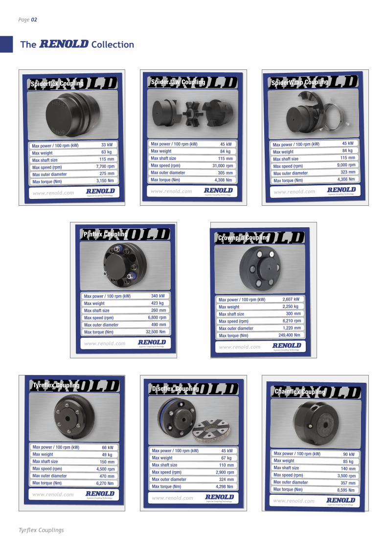
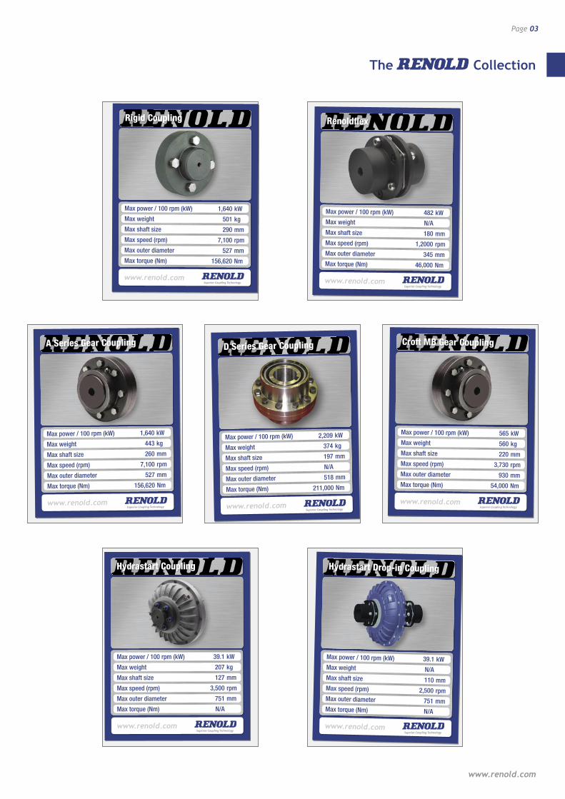
The Renold Collection 02
Coupling Selection Guide 04
Load Classification by Application 05
Service Factors and Selection 06
Key and Keyway Dimensions 07
Tyreflex 08
Renold Chain inside back cover
Page 02
Max power / 100 rpm (kW) 33 kW
Max weight 63 kg
Max shaft size 115 mm
Max speed (rpm) 7,700 rpm
Max outer diameter 275 mm
Max torque (Nm) 3,150 Nm
Spiderflex Coupling
www.renold.com
The Collection
Max power / 100 rpm (kW) 340 kW
Max weight 423 kg
Max shaft size 260 mm
Max speed (rpm) 6,800 rpm
Max outer diameter 490 mm
Max torque (Nm) 32,500 Nm
Pinflex Coupling
www.renold.com
Max power / 100 rpm (kW) 2,607 kW
Max weight 2,250 kg
Max shaft size 300 mm
Max speed (rpm) 6,210 rpm
Max outer diameter 1,220 mm
Max torque (Nm) 249,400 Nm
Crownpin Coupling
www.renold.com
Max power / 100 rpm (kW) 45 kW
Max weight 67 kg
Max shaft size 110 mm
Max speed (rpm) 2,900 rpm
Max outer diameter 324 mm
Max torque (Nm) 4,298 Nm
Discflex Coupling
www.renold.com
Max power / 100 rpm (kW) 90 kWMax weight 85 kgMax shaft size 140 mmMax speed (rpm) 3,500 rpm Max outer diameter 357 mmMax torque (Nm) 8,595 Nm
Chainflex Coupling
www.renold.com
Max power / 100 rpm (kW) 45 kW
Max weight 84 kg
Max shaft size 115 mm
Max speed (rpm) 31,000 rpm
Max outer diameter 305 mm
Max torque (Nm) 4,308 Nm
SpiderJaw Coupling
www.renold.com
Max power / 100 rpm (kW) 66 kWMax weight 49 kgMax shaft size 150 mmMax speed (rpm) 4,500 rpm Max outer diameter 470 mmMax torque (Nm) 6,270 Nm
Tyreflex Coupling
www.renold.com
Tyrflex Couplings
Max power / 100 rpm (kW) 45 kW
Max weight 84 kg
Max shaft size 115 mm
Max speed (rpm) 9,000 rpm
Max outer diameter 323 mm
Max torque (Nm) 4,308 Nm
SpiderWrap Coupling
www.renold.com
www.renold.com
Page 03
Max power / 100 rpm (kW) 1,640 kW
Max weight 443 kg
Max shaft size 260 mm
Max speed (rpm) 7,100 rpm
Max outer diameter 527 mm
Max torque (Nm) 156,620 Nm
A Series Gear Coupling
www.renold.com
Max power / 100 rpm (kW) 39.1 kW
Max weight 207 kg
Max shaft size 127 mm
Max speed (rpm) 3,500 rpm
Max outer diameter 751 mm
Max torque (Nm) N/A
Hydrastart Coupling
www.renold.com
Max power / 100 rpm (kW) 482 kWMax weight N/AMax shaft size 180 mmMax speed (rpm) 1,2000 rpm Max outer diameter 345 mmMax torque (Nm) 46,000 Nm
Renoldflex
www.renold.com
Max power / 100 rpm (kW) 39.1 kWMax weight N/AMax shaft size 110 mmMax speed (rpm) 2,500 rpm Max outer diameter 751 mmMax torque (Nm) N/A
Hydrastart Drop-in Coupling
www.renold.com
Max power / 100 rpm (kW) 1,640 kW
Max weight 501 kg
Max shaft size 290 mm
Max speed (rpm) 7,100 rpm
Max outer diameter 527 mm
Max torque (Nm) 156,620 Nm
Rigid Coupling
www.renold.com
Max power / 100 rpm (kW) 2,209 kW
Max weight 374 kg
Max shaft size 197 mm
Max speed (rpm) N/A
Max outer diameter 518 mm
Max torque (Nm) 211,000 Nm
D Series Gear Coupling
www.renold.com
Max power / 100 rpm (kW) 565 kWMax weight 560 kgMax shaft size 220 mmMax speed (rpm) 3,730 rpm Max outer diameter 930 mmMax torque (Nm) 54,000 Nm
Croft MB Gear Coupling
www.renold.com
The Collection
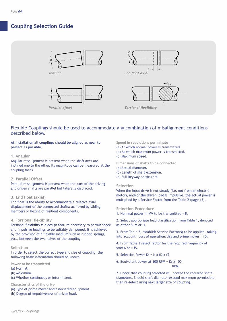
Coupling Selection Guide
Page 04
Tyreflex Couplings
At installation all couplings should be aligned as near to perfect as possible.
1. Angular Angular misalignment is present when the shaft axes are inclined one to the other. Its magnitude can be measured at the coupling faces.
2. Parallel Offset Parallel misalignment is present when the axes of the driving and driven shafts are parallel but laterally displaced.
3. End float (axial) End float is the ability to accommodate a relative axial displacement of the connected shafts; achieved by sliding members or flexing of resilient components.
4. Torsional flexibility Torsional flexibility is a design feature necessary to permit shock and impulsive loadings to be suitably dampened. It is achieved by the provision of a flexible medium such as rubber, springs, etc., between the two halves of the coupling.
Selection In order to select the correct type and size of coupling, the following basic information should be known:
Power to be transmitted (a) Normal. (b) Maximum. (c) Whether continuous or intermittent.
Characteristics of the drive (a) Type of prime mover and associated equipment. (b) Degree of impulsiveness of driven load.
Speed in revolutions per minute (a) At which normal power is transmitted. (b) At which maximum power is transmitted. (c) Maximum speed.
Dimensions of shafts to be connected (a) Actual diameter. (b) Length of shaft extension. (c) Full keyway particulars.
Selection When the input drive is not steady (i.e. not from an electric motor), and/or the driven load is impulsive, the actual power is multiplied by a Service Factor from the Table 2 (page 13).
Selection Procedure 1. Nominal power in kW to be transmitted = K.
2. Select appropriate load classification from Table 1, denoted as either S, M or H.
3. From Table 2, establish Service Factor(s) to be applied, taking into account hours of operation/day and prime mover = fD.
4. From Table 3 select factor for the required frequency of starts/hr = fS.
5. Selection Power Ks = K x fD x fS
6. Equivalent power at 100 RPM = Ks x 100 RPM
7. Check that coupling selected will accept the required shaft diameters. Should shaft diameter exceed maximum permissible, then re-select using next larger size of coupling.
Flexible Couplings should be used to accommodate any combination of misalignment conditions described below.
Ø
ƒ
Ø
O
Angular
Ø
ƒ
Ø
O
Parallel offset
Ø
ƒ
Ø
O
End float axial
Ø
ƒ
Ø
O
Torsional flexibility
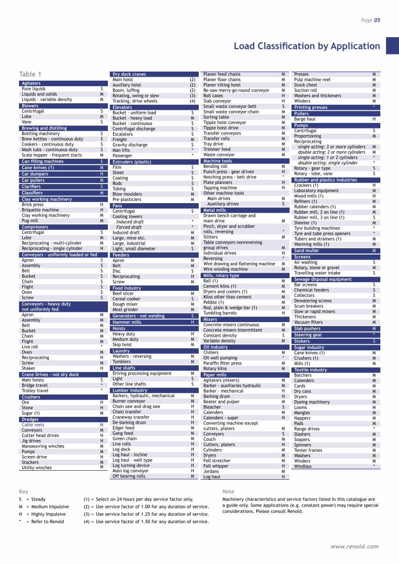
Load Classification by Application
Page 05
www.renold.com
Agitators Pure liquids S Liquids and solids M Liquids - variable density MBlowers Centrifugal S Lobe M Vane SBrewing and distilling Bottling machinery S Brew kettles - continuous duty S Cookers - continuous duty S Mash tubs - continuous duty S Scale hopper - frequent starts MCan filling machines SCane knives (1) MCar dumpers HCar pullers MClarifiers SClassifiers MClay working machinery Brick press H Briquette machine H Clay working machinery M Pug mill MCompressors Centrifugal S Lobe M Reciprocating - multi-cylinder M Reciprocating - single cylinder HConveyors - uniformly loaded or fed Apron S Assembly S Belt S Bucket S Chain S Flight S Oven S Screw SConveyors - heavy duty not uniformly fed Apron M Assembly M Belt M Bucket M Chain M Flight M Live roll * Oven M Reciprocating H Screw M Shaker HCrane Drives - not dry dock Main hoists S Bridge travel * Trolley travel *Crushers Ore H Stone H Sugar (1) MDredges Cable reels M Conveyors M Cutter head drives H Jig drives H Manoeuvring winches M Pumps M Screen drive H Stackers M Utility winches M
Dry dock cranes Main hoist (2) Auxiliary hoist (2) Boom, luffing (2) Rotating, swing or slew (3) Tracking, drive wheels (4)Elevators Bucket - uniform load S Bucket - heavy load M Bucket - continuous S Centrifugal discharge S Escalators S Freight M Gravity discharge S Man lifts * Passenger *Extruders (plastic) Film S Sheet S Coating S Rods S Tubing S Blow moulders M Pre-plasticiers MFans Centrifugal S Cooling towers Induced draft * Forced draft * Induced draft M Large, mine etc. M Large, industrial M Light, small diameter SFeeders Apron M Belt M Disc S Reciprocating H Screw MFood industry Beef slicer M Cereal cooker S Dough mixer M Meat grinder MGenerators - not welding SHammer mills HHoists Heavy duty H Medium duty M Skip hoist MLaundry Washers - reversing M Tumblers MLine shafts Driving processing equipment M Light S Other line shafts SLumber industry Barkers, hydraulic, mechanical M Burner conveyor M Chain saw and drag saw H Chain transfer H Craneway transfer H De-barking drum H Edger feed M Gang feed M Green chain M Live rolls H Log deck H Log haul - incline H Log haul - well type H Log turning device H Main log conveyor H Off bearing rolls M
Planer feed chains M Planer floor chains M Planer tilting hoist M Re-saw merry-go-round conveyor M Roll cases H Slab conveyor H Small waste conveyor-belt S Small waste conveyor-chain M Sorting table M Tipple hoist conveyor M Tipple hoist drive M Transfer conveyors M Transfer rolls M Tray drive M Trimmer feed M Waste conveyor MMachine tools Bending roll M Punch press - gear driven H Notching press - belt drive * Plate planners H Tapping machine H Other machine tools Main drives M Auxiliary drives SMetal mills Drawn bench carriage and main drive M Pinch, dryer and scrubber rolls, reversing * Slitters M Table conveyors nonreversing group drives M Individual drives H Reversing * Wire drawing and flattening machine M Wire winding machine MMills, rotary type Ball (1) M Cement kilns (1) M Dryers and coolers (1) M Kilns other than cement M Pebble (1) M Rod, plain & wedge bar (1) M Tumbling barrels HMixers Concrete mixers continuous M Concrete mixers intermittent M Constant density S Variable density MOil industry Chillers M Oil well pumping * Paraffin filter press M Rotary kilns MPaper mills Agitators (mixers) M Barker - auxiliaries hydraulic M Barker - mechanical H Barking drum H Beater and pulper M Bleacher S Calenders M Calenders - super H Converting machine except cutters, platers M Conveyors S Couch M Cutters, platers H Cylinders M Dryers M Fell stretcher M Fell whipper H Jordans M Log haul H
Presses M Pulp machine reel M Stock chest M Suction roll M Washers and thickeners M Winders MPrinting presses *Pullers Barge haul HPumps Centrifugal S Proportioning M Reciprocating single acting: 3 or more cylinders M double acting: 2 or more cylinders M single acting: 1 or 2 cylinders * double acting: single cylinder * Rotary - gear type S Rotary - lobe, vane SRubber and plastics industries Crackers (1) H Laboratory equipment M Mixed mills (1) H Refiners (1) M Rubber calenders (1) M Rubber mill, 2 on line (1) M Rubber mill, 3 on line (1) S Sheeter (1) M Tyre building machines * Tyre and tube press openers * Tubers and strainers (1) M Warming mills (1) MSand muller MScreens Air washing S Rotary, stone or gravel M Travelling water intake SSewage disposal equipment Bar screens S Chemical feeders S Collectors S Dewatering screws M Scum breakers M Slow or rapid mixers M Thickeners M Vacuum filters MSlab pushers MSteering gear *Stokers SSugar industry Cane knives (1) M Crushers (1) M Mills (1) MTextile industry Batchers M Calenders M Cards M Dry cans M Dryers M Dyeing machinery M Looms M Mangles M Nappers M Pads M Range drives * Slashers M Soapers M Spinners M Tenter frames M Washers M Winders M Windlass *
Table 1
KeyS = Steady
M = Medium Impulsive
H = Highly Impulsive
* = Refer to Renold
(1) = Select on 24 hours per day service factor only.
(2) = Use service factor of 1.00 for any duration of service.
(3) = Use service factor of 1.25 for any duration of service.
(4) = Use service factor of 1.50 for any duration of service.
NoteMachinery characteristics and service factors listed in this catalogue are a guide only. Some applications (e.g. constant power) may require special considerations. Please consult Renold.
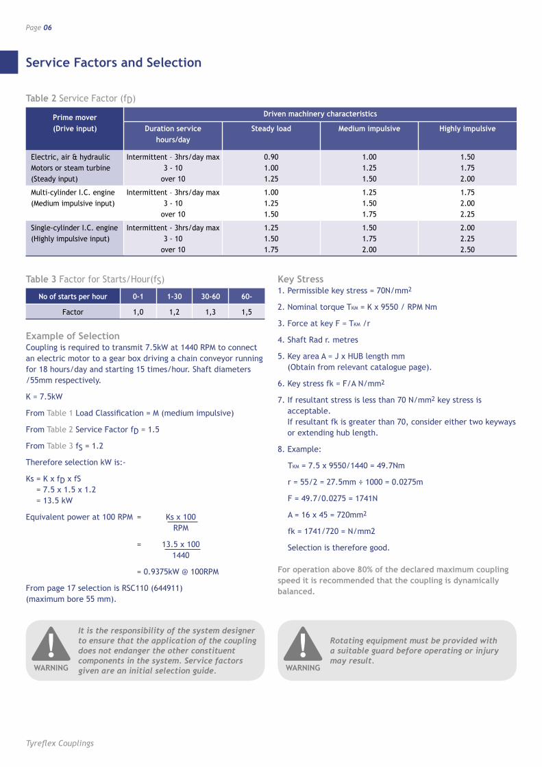
Service Factors and Selection
Page 06
Tyreflex Couplings
Example of Selection Coupling is required to transmit 7.5kW at 1440 RPM to connect an electric motor to a gear box driving a chain conveyor running for 18 hours/day and starting 15 times/hour. Shaft diameters /55mm respectively.
K = 7.5kW
From Table 1 Load Classification = M (medium impulsive)
From Table 2 Service Factor fD = 1.5
From Table 3 fS = 1.2
Therefore selection kW is:-
Ks = K x fD x fS = 7.5 x 1.5 x 1.2 = 13.5 kW
Equivalent power at 100 RPM = Ks x 100 RPM
= 13.5 x 100 1440
= 0.9375kW @ 100RPM
From page 17 selection is RSC110 (644911) (maximum bore 55 mm).
Key Stress 1. Permissible key stress = 70N/mm2
2. Nominal torque TKM = K x 9550 / RPM Nm
3. Force at key F = TKM /r
4. Shaft Rad r. metres
5. Key area A = J x HUB length mm (Obtain from relevant catalogue page).
6. Key stress fk = F/A N/mm2
7. If resultant stress is less than 70 N/mm2 key stress is acceptable. If resultant fk is greater than 70, consider either two keyways or extending hub length.
8. Example:
TKM = 7.5 x 9550/1440 = 49.7Nm
r = 55/2 = 27.5mm ÷ 1000 = 0.0275m
F = 49.7/0.0275 = 1741N
A = 16 x 45 = 720mm2
fk = 1741/720 = N/mm2
Selection is therefore good.
For operation above 80% of the declared maximum coupling speed it is recommended that the coupling is dynamically balanced.
Prime mover Driven machinery characteristics
(Drive input) Duration service Steady load Medium impulsive Highly impulsive hours/day
Electric, air & hydraulic Intermittent – 3hrs/day max 0.90 1.00 1.50 Motors or steam turbine 3 - 10 1.00 1.25 1.75 (Steady input) over 10 1.25 1.50 2.00
Multi-cylinder I.C. engine Intermittent – 3hrs/day max 1.00 1.25 1.75 (Medium impulsive input) 3 - 10 1.25 1.50 2.00 over 10 1.50 1.75 2.25
Single-cylinder I.C. engine Intermittent - 3hrs/day max 1.25 1.50 2.00 (Highly impulsive input) 3 - 10 1.50 1.75 2.25 over 10 1.75 2.00 2.50
Table 2 Service Factor (fD)
No of starts per hour 0-1 1-30 30-60 60-
Factor 1,0 1,2 1,3 1,5
Table 3 Factor for Starts/Hour(fS)
It is the responsibility of the system designer to ensure that the application of the coupling does not endanger the other constituent components in the system. Service factors given are an initial selection guide.
!WARNING
Rotating equipment must be provided with a suitable guard before operating or injury may result.
!WARNING
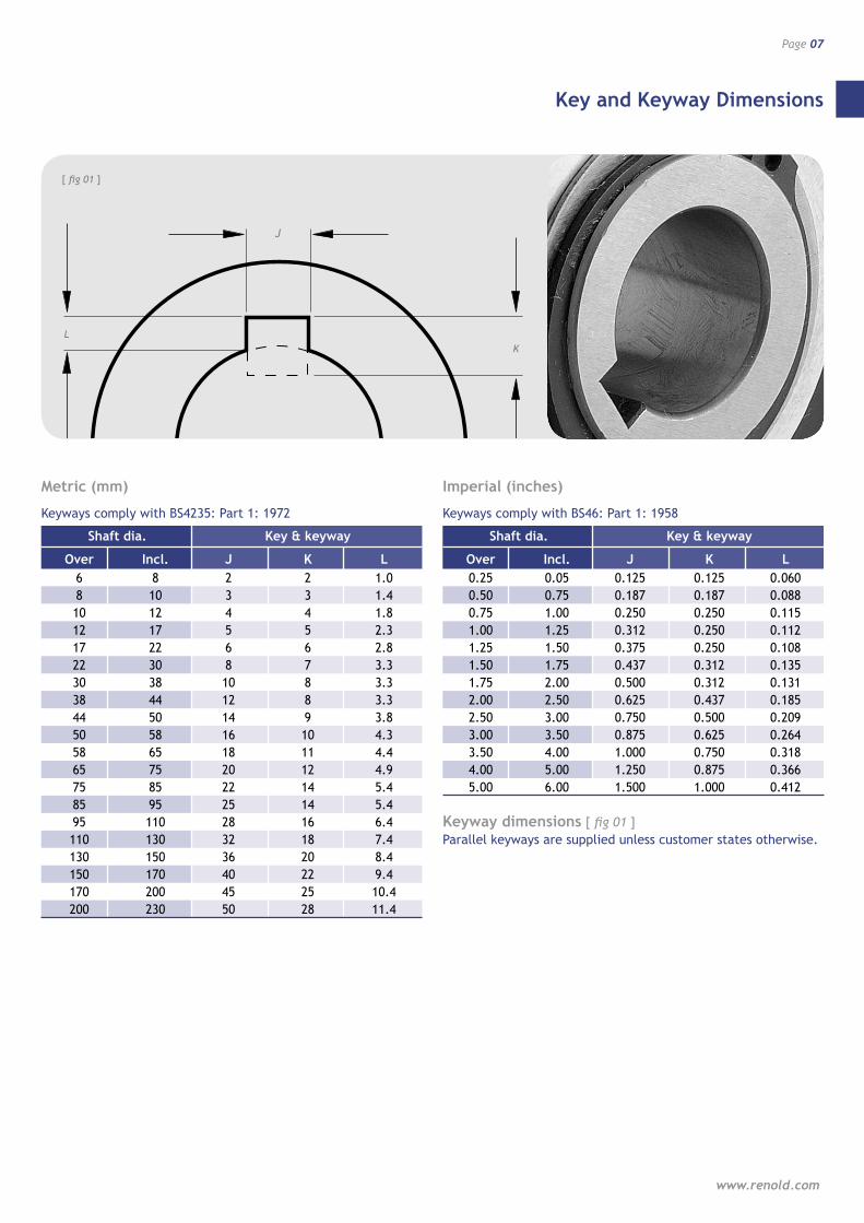
Key and Keyway Dimensions
Page 07
www.renold.com
L
J
[ fig 01 ]
K
L
J
pag
e 8
A/W
’s
K
Metric (mm)
Keyways comply with BS4235: Part 1: 1972
Shaft dia. Key & keyway
Over Incl. J K L 6 8 2 2 1.0 8 10 3 3 1.4 10 12 4 4 1.8 12 17 5 5 2.3 17 22 6 6 2.8 22 30 8 7 3.3 30 38 10 8 3.3 38 44 12 8 3.3 44 50 14 9 3.8 50 58 16 10 4.3 58 65 18 11 4.4 65 75 20 12 4.9 75 85 22 14 5.4 85 95 25 14 5.4 95 110 28 16 6.4 110 130 32 18 7.4 130 150 36 20 8.4 150 170 40 22 9.4 170 200 45 25 10.4 200 230 50 28 11.4
Imperial (inches)
Keyways comply with BS46: Part 1: 1958
Shaft dia. Key & keyway
Over Incl. J K L 0.25 0.05 0.125 0.125 0.060 0.50 0.75 0.187 0.187 0.088 0.75 1.00 0.250 0.250 0.115 1.00 1.25 0.312 0.250 0.112 1.25 1.50 0.375 0.250 0.108 1.50 1.75 0.437 0.312 0.135 1.75 2.00 0.500 0.312 0.131 2.00 2.50 0.625 0.437 0.185 2.50 3.00 0.750 0.500 0.209 3.00 3.50 0.875 0.625 0.264 3.50 4.00 1.000 0.750 0.318 4.00 5.00 1.250 0.875 0.366 5.00 6.00 1.500 1.000 0.412
Keyway dimensions [ fig 01 ] Parallel keyways are supplied unless customer states otherwise.
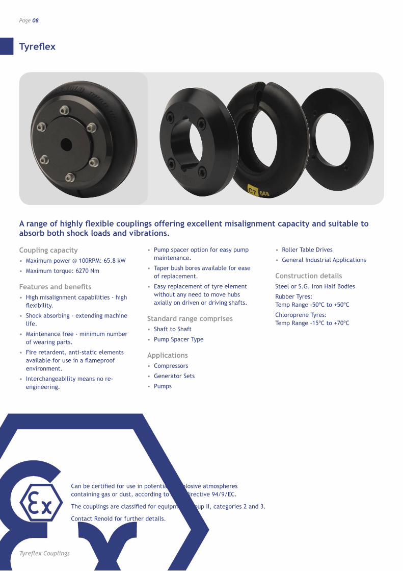
Tyreflex
Page 08
Tyreflex Couplings
A range of highly flexible couplings offering excellent misalignment capacity and suitable to absorb both shock loads and vibrations.
Coupling capacity• Maximum power @ 100RPM: 65.8 kW
• Maximum torque: 6270 Nm
Features and benefits• High misalignment capabilities - high
flexibility.
• Shock absorbing - extending machine life.
• Maintenance free - minimum number of wearing parts.
• Fire retardent, anti-static elements available for use in a flameproof environment.
• Interchangeability means no re-engineering.
• Pump spacer option for easy pump maintenance.
• Taper bush bores available for ease of replacement.
• Easy replacement of tyre element without any need to move hubs axially on driven or driving shafts.
Standard range comprises• Shaft to Shaft
• Pump Spacer Type
Applications• Compressors
• Generator Sets
• Pumps
• Roller Table Drives
• General Industrial Applications
Construction detailsSteel or S.G. Iron Half Bodies
Rubber Tyres: Temp Range -50ºC to +50ºC
Chloroprene Tyres: Temp Range -15ºC to +70ºC
Can be certified for use in potentially explosive atmospheres containing gas or dust, according to ATEX directive 94/9/EC.
The couplings are classified for equipment group II, categories 2 and 3.
Contact Renold for further details.
Tyreflex
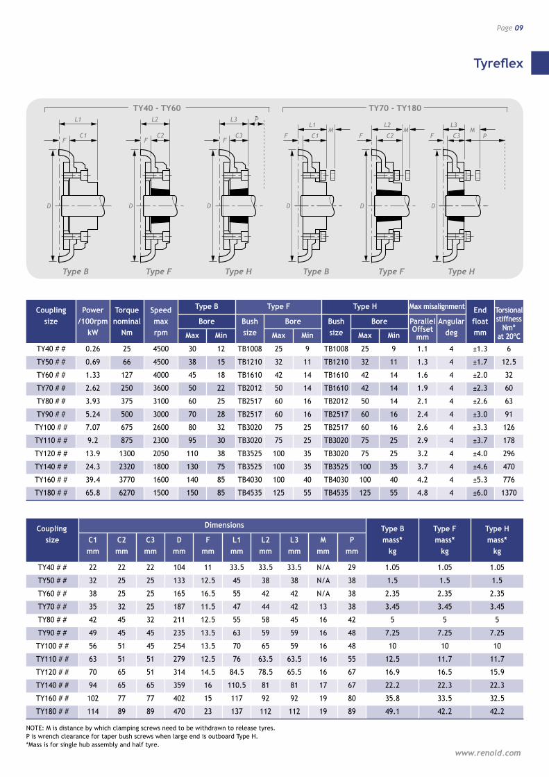
Page 09
www.renold.com
D
L1
FC1
D
L2
FC2
D
L3 P
FC3
D
L1F
MC1
D
L2F
MC2
D
L3 F P
MC3
F
L1
C1
D D D
F
L2
C2F
L3
C3
P
DD
F
L1
C1M
F
L2
C2M
D
F
L3
C3M
P
Coupling Power Torque Speed Type B Type F Type H Max misalignment End size /100rpm nominal max Bore Bush Bore Bush Bore Angular float kW Nm rpm Max Min size Max Min size Max Min deg mm
TY40 # # 0.26 25 4500 30 12 TB1008 25 9 TB1008 25 9 1.1 4 ±1.3 6
TY50 # # 0.69 66 4500 38 15 TB1210 32 11 TB1210 32 11 1.3 4 ±1.7 12.5
TY60 # # 1.33 127 4000 45 18 TB1610 42 14 TB1610 42 14 1.6 4 ±2.0 32
TY70 # # 2.62 250 3600 50 22 TB2012 50 14 TB1610 42 14 1.9 4 ±2.3 60
TY80 # # 3.93 375 3100 60 25 TB2517 60 16 TB2012 50 14 2.1 4 ±2.6 63
TY90 # # 5.24 500 3000 70 28 TB2517 60 16 TB2517 60 16 2.4 4 ±3.0 91
TY100 # # 7.07 675 2600 80 32 TB3020 75 25 TB2517 60 16 2.6 4 ±3.3 126
TY110 # # 9.2 875 2300 95 30 TB3020 75 25 TB3020 75 25 2.9 4 ±3.7 178
TY120 # # 13.9 1300 2050 110 38 TB3525 100 35 TB3020 75 25 3.2 4 ±4.0 296
TY140 # # 24.3 2320 1800 130 75 TB3525 100 35 TB3525 100 35 3.7 4 ±4.6 470
TY160 # # 39.4 3770 1600 140 85 TB4030 100 40 TB4030 100 40 4.2 4 ±5.3 776
TY180 # # 65.8 6270 1500 150 85 TB4535 125 55 TB4535 125 55 4.8 4 ±6.0 1370
Coupling Dimensions Type B Type F Type H size C1 C2 C3 D F L1 L2 L3 M P mass* mass* mass* mm mm mm mm mm mm mm mm mm mm kg kg kg
TY40 # # 22 22 22 104 11 33.5 33.5 33.5 N/A 29 1.05 1.05 1.05
TY50 # # 32 25 25 133 12.5 45 38 38 N/A 38 1.5 1.5 1.5
TY60 # # 38 25 25 165 16.5 55 42 42 N/A 38 2.35 2.35 2.35
TY70 # # 35 32 25 187 11.5 47 44 42 13 38 3.45 3.45 3.45
TY80 # # 42 45 32 211 12.5 55 58 45 16 42 5 5 5
TY90 # # 49 45 45 235 13.5 63 59 59 16 48 7.25 7.25 7.25
TY100 # # 56 51 45 254 13.5 70 65 59 16 48 10 10 10
TY110 # # 63 51 51 279 12.5 76 63.5 63.5 16 55 12.5 11.7 11.7
TY120 # # 70 65 51 314 14.5 84.5 78.5 65.5 16 67 16.9 16.5 15.9
TY140 # # 94 65 65 359 16 110.5 81 81 17 67 22.2 22.3 22.3
TY160 # # 102 77 77 402 15 117 92 92 19 80 35.8 33.5 32.5
TY180 # # 114 89 89 470 23 137 112 112 19 89 49.1 42.2 42.2
NOTE: M is distance by which clamping screws need to be withdrawn to release tyres. P is wrench clearance for taper bush screws when large end is outboard Type H. *Mass is for single hub assembly and half tyre.
Type B Type B Type F Type HType HType F
TY40 - TY60 TY70 - TY180
Torsional stiffness
Nmº at 20ºC
Parallel Offset mm
Tyreflex
Tyreflex Couplings
Page 10
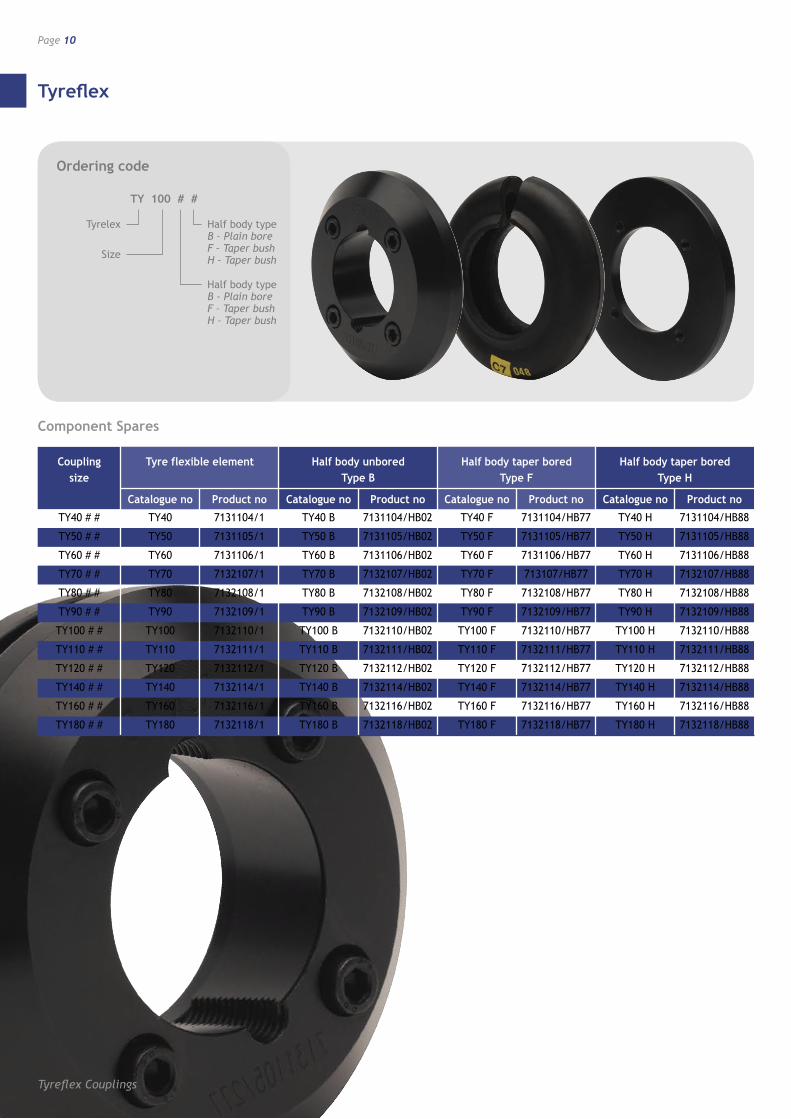
Component Spares
Ordering code
TY 100 # #
Tyrelex
Size
Half body type B – Plain bore F – Taper bush H – Taper bush
Half body type B – Plain bore F – Taper bush H – Taper bush
Coupling Tyre flexible element Half body unbored Half body taper bored Half body taper bored size Type B Type F Type H
Catalogue no Product no Catalogue no Product no Catalogue no Product no Catalogue no Product no
TY40 # # TY40 7131104/1 TY40 B 7131104/HB02 TY40 F 7131104/HB77 TY40 H 7131104/HB88
TY50 # # TY50 7131105/1 TY50 B 7131105/HB02 TY50 F 7131105/HB77 TY50 H 7131105/HB88
TY60 # # TY60 7131106/1 TY60 B 7131106/HB02 TY60 F 7131106/HB77 TY60 H 7131106/HB88
TY70 # # TY70 7132107/1 TY70 B 7132107/HB02 TY70 F 713107/HB77 TY70 H 7132107/HB88
TY80 # # TY80 7132108/1 TY80 B 7132108/HB02 TY80 F 7132108/HB77 TY80 H 7132108/HB88
TY90 # # TY90 7132109/1 TY90 B 7132109/HB02 TY90 F 7132109/HB77 TY90 H 7132109/HB88
TY100 # # TY100 7132110/1 TY100 B 7132110/HB02 TY100 F 7132110/HB77 TY100 H 7132110/HB88
TY110 # # TY110 7132111/1 TY110 B 7132111/HB02 TY110 F 7132111/HB77 TY110 H 7132111/HB88
TY120 # # TY120 7132112/1 TY120 B 7132112/HB02 TY120 F 7132112/HB77 TY120 H 7132112/HB88
TY140 # # TY140 7132114/1 TY140 B 7132114/HB02 TY140 F 7132114/HB77 TY140 H 7132114/HB88
TY160 # # TY160 7132116/1 TY160 B 7132116/HB02 TY160 F 7132116/HB77 TY160 H 7132116/HB88
TY180 # # TY180 7132118/1 TY180 B 7132118/HB02 TY180 F 7132118/HB77 TY180 H 7132118/HB88
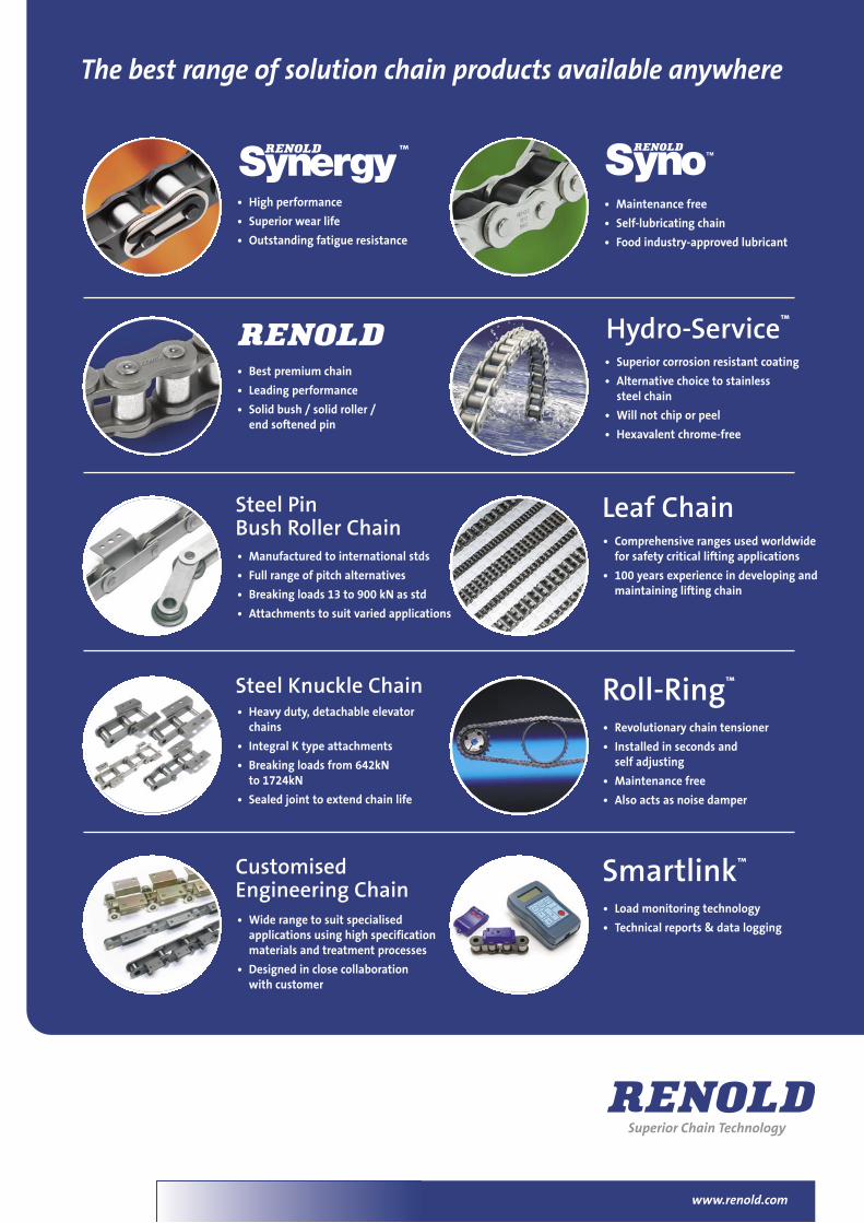
• High performance
• Superior wear life
• Outstanding fatigue resistance
• Best premium chain
• Leading performance
• Solid bush / solid roller /end softened pin
• Manufactured to international stds
• Full range of pitch alternatives
• Breaking loads 13 to 900 kN as std
• Attachments to suit varied applications
• Superior corrosion resistant coating
• Alternative choice to stainlesssteel chain
• Will not chip or peel
• Hexavalent chrome-free
• Comprehensive ranges used worldwidefor safety critical lifting applications
• 100 years experience in developing andmaintaining lifting chain
Hydro-Service™
Leaf Chain
™
www.renold.com
• Heavy duty, detachable elevatorchains
• Integral K type attachments
• Breaking loads from 642kNto 1724kN
• Sealed joint to extend chain life
• Wide range to suit specialisedapplications using high specificationmaterials and treatment processes
• Designed in close collaborationwith customer
• Revolutionary chain tensioner
• Installed in seconds andself adjusting
• Maintenance free
• Also acts as noise damper
Roll-Ring™
• Load monitoring technology
• Technical reports & data logging
Smartlink™
Steel PinBush Roller Chain
Steel Knuckle Chain
CustomisedEngineering Chain
The best range of solution chain products available anywhere
• Maintenance free
• Self-lubricating chain
• Food industry-approved lubricant
36073 A4 1pp chain overview.qxd:A4 30/6/10 13:09 Page 1
www.renold.com
UK Renold Clutches & Couplings Cardiff Tel + 44 (0) 29 20792737 Fax + 44 (0) 29 20791360 [email protected]
Renold Hi-Tec Couplings Halifax Tel + 44 (0) 1422 255000 Fax + 44 (0) 1422 320273 [email protected]
Renold Gears Milnrow Tel + 44 (0) 1706 751000 Fax + 44 (0) 1706 751001 [email protected]
USA Renold Ajax Westfield, New York State Tel +1 716 326 3121 Fax + 1 716 326 8229 [email protected]
WEB www.renold.com
E-MAIL [email protected]
For you nearest Renold dedicated specialist or distributor please visit the Renold website - www.renold.com or contact Renold UK
Whilst all reasonable care in compiling the information contained in this brochure is taken, no responsibility is accepted for printing errors. All information contained in this brochure is subject to change after the date of publication.
RE
V03
04/
13