Embed Size (px)
Citation preview
White Paper
ACPI Based “Platform Communication Channel” (PCC) Mechanism
InSarathy Jayakumar
Intel Corporation
October 2015

2
Executive Summary This paper presents a detailed explanation of the APCI defined Platform Communication Channel (PCC) Mechanism and its usage model. Please refer to the ACPI Specification at http://www.uefi.org/sites/default/files/resources/ACPI_6.0.pdf
Table of Contents
1. OVERVIEW ......................................................................................................................................................... 5
1.1 PCC SHARED MEMORY REGION ................................................................................................................. 5 1.2 PCCT TABLE ............................................................................................................................................... 6
2. PUTTING IT ALL TOGETHER ........................................................................................................................ 7
2.1 ESTABLISHING CORRELATION BETWEEN THE TABLES ................................................................................. 7 2.2 OSPM SEQUENCE FOR INVOKING THE PLATFORM ENTITY ......................................................................... 8
Setting up the Parameters ................................................................................................................... 8
3. EXECUTION AND EVENT INTERFACE ..................................................................................................... 11
3.1 PCC EXECUTION ....................................................................................................................................... 11 3.2 EXECUTION COMPLETE NOTIFICATION ...................................................................................................... 11 3.3 DETERMINING EVENT COMPLETE BY POLLING ......................................................................................... 12 3.4 ASYNCHRONOUS EVENT NOTIFICATION .................................................................................................... 12
4. FLOWCHARTS SUMMARIZING THE PCC MECHANISM ...................................................................... 13
White Paper
4
Figures
Figure 1-1 RASF Table example showing the “PCC Identifier” .................................................... 5
Figure 1-2 PCCT ACPI Table ...................................................................................................... 6
Figure 2-1 Locating the PCC Shared Memory Region ................................................................. 7
Figure 2-2 PCC Subspace Structure ........................................................................................... 8
Figure 2-3 PCC Shared Memory Region slot .............................................................................. 9
Figure 2-4 RASF command code .............................................................................................. 10
Figure 4-1 OSPM Invocation of PCC – Using RASF Example ................................................... 13
Figure 4-2 OSPM Processing of SCI due to a PCC event ......................................................... 14
1. Overview
Platform Communication Channel (PCC) is an ACPI Specification defined mechanism for PC and server platforms, as a standard mechanism for bi-directional communication between a platform entity such as System Firmware or Management controller and the Operating System (OSPM).
PCC is a generic mechanism, a plumbing, which is available for other ACPI based features to employ. Examples of some of the ACPI based features that employ PCC for establishing communication between the platform entity and the OSPM are RASF, MPST etc.
NOTE: In the remainder of this document, the term “ACPI Feature” or “Feature” is used to denote an ACPI based technology that employ PCC Mechanism. The RASF ACPI feature will be used as an example to demonstrate the usage of PCC mechanism and can serve as a template for defining future ACPI features that employ PCC mechanism.
1.1 PCC Shared Memory Region
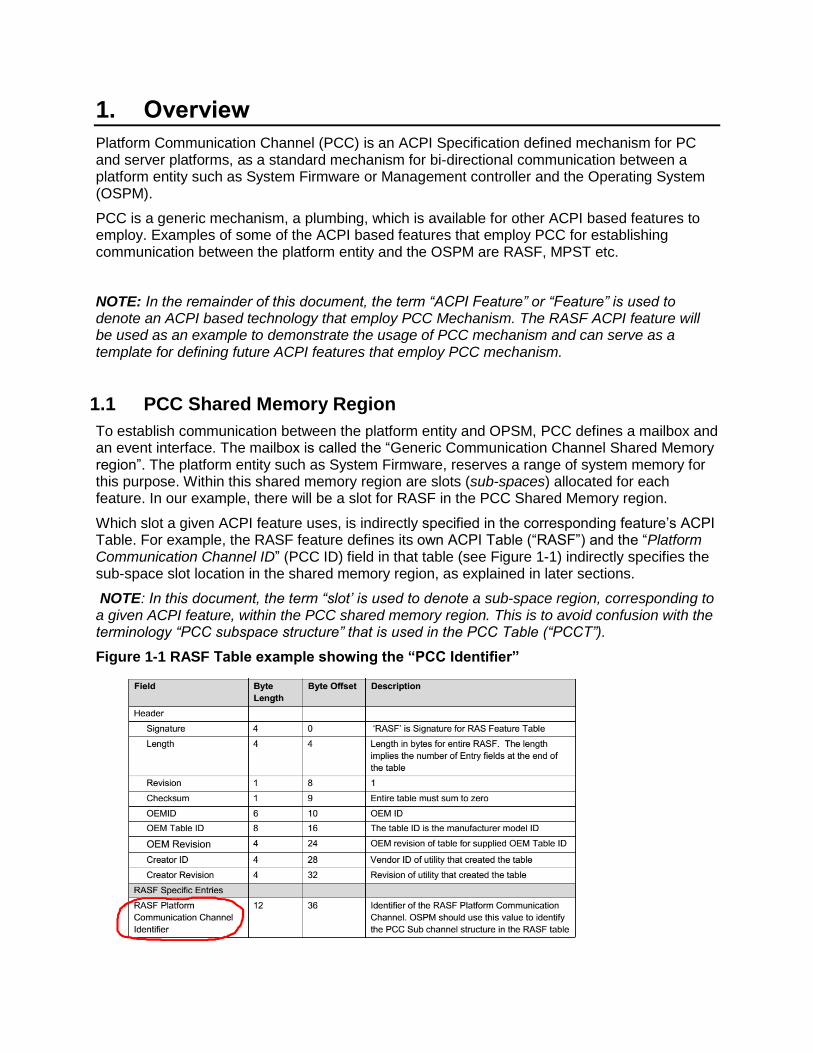
To establish communication between the platform entity and OPSM, PCC defines a mailbox and an event interface. The mailbox is called the “Generic Communication Channel Shared Memory region”. The platform entity such as System Firmware, reserves a range of system memory for this purpose. Within this shared memory region are slots (sub-spaces) allocated for each feature. In our example, there will be a slot for RASF in the PCC Shared Memory region.
Which slot a given ACPI feature uses, is indirectly specified in the corresponding feature’s ACPI Table. For example, the RASF feature defines its own ACPI Table (“RASF”) and the “Platform Communication Channel ID” (PCC ID) field in that table (see Figure 1-1) indirectly specifies the sub-space slot location in the shared memory region, as explained in later sections.
NOTE: In this document, the term “slot’ is used to denote a sub-space region, corresponding to a given ACPI feature, within the PCC shared memory region. This is to avoid confusion with the terminology “PCC subspace structure” that is used in the PCC Table (“PCCT”).
Figure 1-1 RASF Table example showing the “PCC Identifier”
White Paper
6
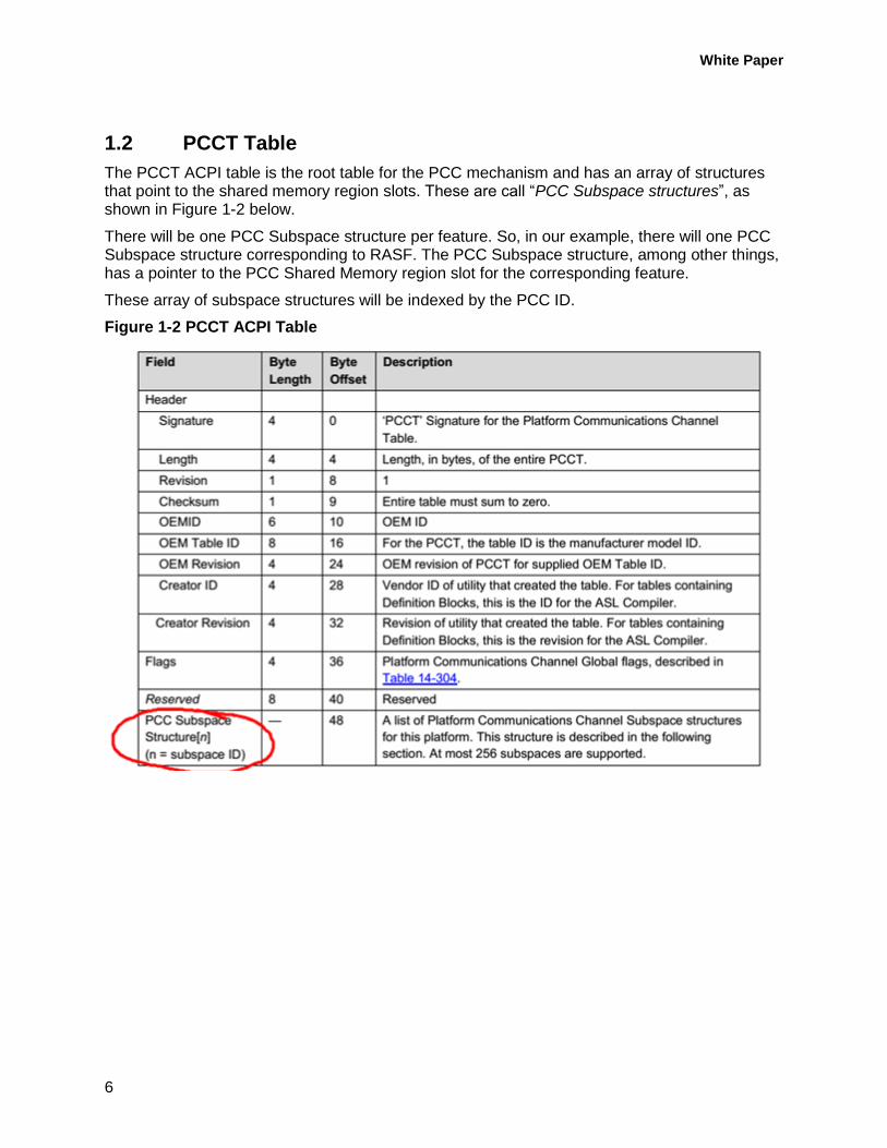
1.2 PCCT Table
The PCCT ACPI table is the root table for the PCC mechanism and has an array of structures that point to the shared memory region slots. These are call “PCC Subspace structures”, as shown in Figure 1-2 below.
There will be one PCC Subspace structure per feature. So, in our example, there will one PCC Subspace structure corresponding to RASF. The PCC Subspace structure, among other things, has a pointer to the PCC Shared Memory region slot for the corresponding feature.
These array of subspace structures will be indexed by the PCC ID.
Figure 1-2 PCCT ACPI Table
2. Putting it all together
As seen in the previous section, each ACPI Feature that uses the PCC Mechanism will have:
1. An ACPI table for that feature (e.g. RASF)
a. The value placed in the “PCC ID” field of this table identifies this feature to PCC
2. A PCC subspace structure corresponding to this feature in the PCCT ACPI table
a. This PCC subspace structure will be indexed by the PCC ID value
b. This PCC subspace structure will point to the corresponding slot in the PCC Shared Memory region.
2.1 Establishing Correlation between the tables
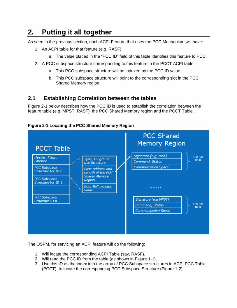
Figure 2-1 below describes how the PCC ID is used to establish the correlation between the feature table (e.g. MPST, RASF), the PCC Shared Memory region and the PCCT Table.
Figure 2-1 Locating the PCC Shared Memory Region
The OSPM, for servicing an ACPI feature will do the following:
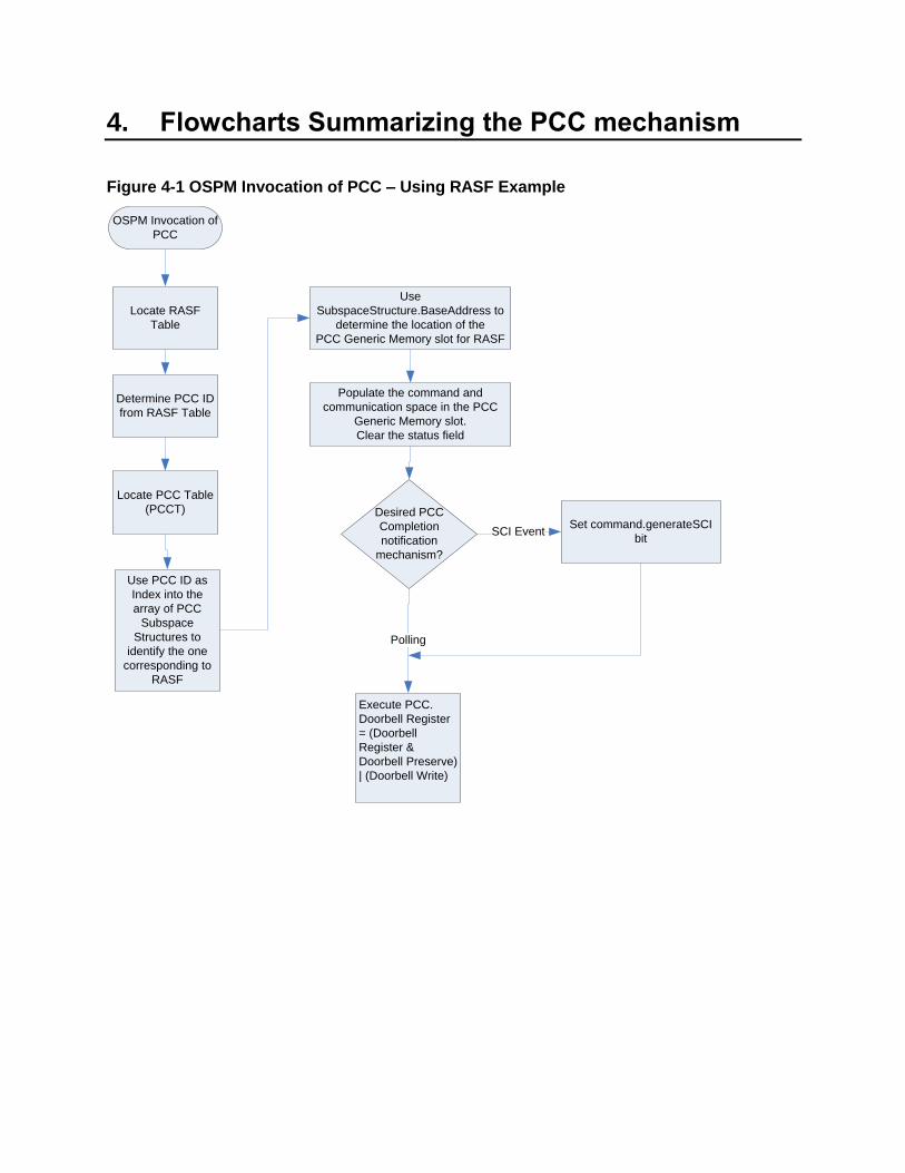
1. Will locate the corresponding ACPI Table (say, RASF). 2. Will read the PCC ID from the table (as shown in Figure 1-1). 3. Use this ID as the index into the array of PCC Subspace structures in ACPI PCC Table.
(PCCT), to locate the corresponding PCC Subspace Structure (Figure 1-2).
White Paper
8
4. Uses the information in the PCC Subspace Structure to locate the corresponding slot in “PCC Shared Memory Region”.
5. Uses the slot in the “PCC Shared Memory Region” as the communication mailbox.
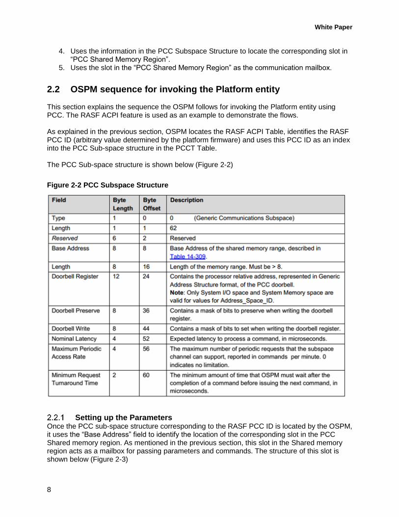
2.2 OSPM sequence for invoking the Platform entity This section explains the sequence the OSPM follows for invoking the Platform entity using PCC. The RASF ACPI feature is used as an example to demonstrate the flows. As explained in the previous section, OSPM locates the RASF ACPI Table, identifies the RASF PCC ID (arbitrary value determined by the platform firmware) and uses this PCC ID as an index into the PCC Sub-space structure in the PCCT Table. The PCC Sub-space structure is shown below (Figure 2-2)
Figure 2-2 PCC Subspace Structure
Setting up the Parameters Once the PCC sub-space structure corresponding to the RASF PCC ID is located by the OSPM, it uses the “Base Address” field to identify the location of the corresponding slot in the PCC Shared memory region. As mentioned in the previous section, this slot in the Shared memory region acts as a mailbox for passing parameters and commands. The structure of this slot is shown below (Figure 2-3)
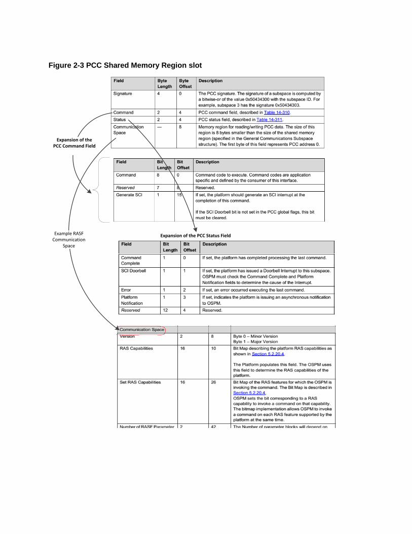
Figure 2-3 PCC Shared Memory Region slot
Expansion of the PCC Command Field
Expansion of the PCC Status FieldExample RASFCommunication
Space
White Paper
10
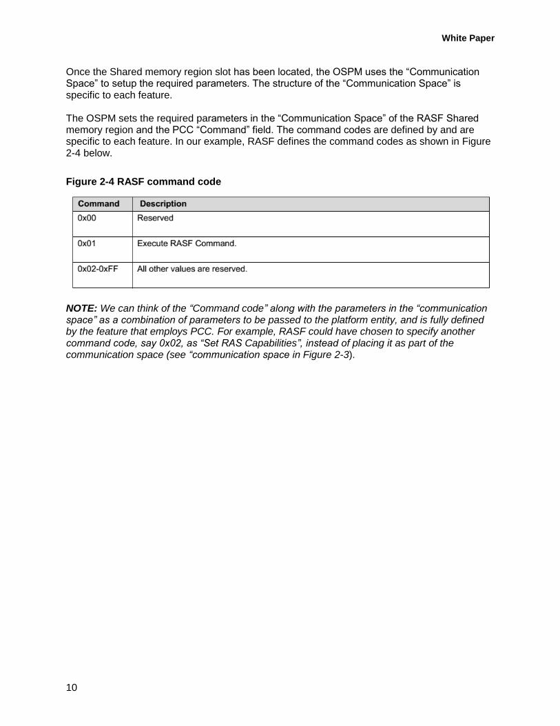
Once the Shared memory region slot has been located, the OSPM uses the “Communication Space” to setup the required parameters. The structure of the “Communication Space” is specific to each feature. The OSPM sets the required parameters in the “Communication Space” of the RASF Shared memory region and the PCC “Command” field. The command codes are defined by and are specific to each feature. In our example, RASF defines the command codes as shown in Figure 2-4 below.
Figure 2-4 RASF command code
NOTE: We can think of the “Command code” along with the parameters in the “communication space” as a combination of parameters to be passed to the platform entity, and is fully defined by the feature that employs PCC. For example, RASF could have chosen to specify another command code, say 0x02, as “Set RAS Capabilities”, instead of placing it as part of the communication space (see “communication space in Figure 2-3).
3. Execution and Event Interface
The previous section explained how the OSPM identifies the slot in the PCC subspace structure that corresponds to a given feature. After setting up the “command” and “communication space” parameters, the OSPM will invoke the platform PCC flow. This section describes how the OPSM invokes the platform PCC flow.
3.1 PCC Execution Please refer back to “Figure 2-2 PCC Subspace Structure”. The “Doorbell Register”, “Doorbell Preserve” and “Doorbell write” fields are used by the OSPM to invoke the platform PCC flow. These fields, populated by the platform entity during boot-up, informs the OSPM as to the mechanism the OSPM should use to invoke the platform entity. The “Doorbell Register” utilizes the ACPI defined standard “Generic Address Structure” (GAS). Please refer to the ACPI specification for the definition of the GAS structure. The GAS structure provides a mechanism to refer to any register (System Memory, IO, PCIe space etc.). The system firmware populates the “Doorbell register” to point to the register that the OSPM has to write to, to invoke the platform PCC flow. It also populates the “Doorbell preserve” and “Doorbell Write” fields to inform the OSPM of the value that it should write to the specified register. The “Doorbell preserve” and “Doorbell Write” fields provide the AND Mask and OR Mask for a read-modify-write semantics. In essence, Doorbell Register = (Doorbell Register & Doorbell Preserve) | (Doorbell Write) Writing to “Doorbell register” executes the platform PCC flow.
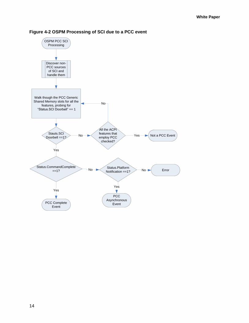
3.2 Execution Complete Notification If the OSPM desires to be notified the completion of the PCC event, it can choose to set the “Generate SCI” bit in the command field of the PCC Generic communication structure (please refer to Figure 2-3 PCC Shared Memory Region slot) before executing PCC. Once the execution of PCC is completed by the platform entity, it will generate a SCI (ACPI Interrupt; please refer to the ACPI Specification) to notify the OSPM. To enable the OSPM to determine the cause of the SCI, the platform entity will set the “SCI Doorbell” bit in the Status field on the PCC Generic communication structure (please refer to Figure 2-3 PCC Shared Memory Region slot) along with the “command complete” bit. On receipt of a SCI event, OSPM should query the “SCI Doorbell” bit in the “Status” field of the PCC Generic communications structure to determine which slot (e.g. RASF) was responsible for triggering the SCI event, then probe the “Command Complete” field in the same structure to determine if the SCI event is due to completion of a previous PCC command (as opposed to a asynchronous SCI, described in section 3.4)
White Paper
12
3.3 Determining Event Complete by Polling If the OSPM chooses to poll for PCC completion instead of a SCI notification, it shouldn’t set the “Generate SCI” bit, but instead utilize the “Nominal Latency” value provided in the “PCC Subspace structure” (refer Figure 2-2 PCC Subspace Structure) to determine the polling interval. By polling the “Command Complete” bit in the “Status” field (Figure 2-3 PCC Shared Memory Region slot), OSPM can determine the completion of the previously issued PCC command.
3.4 Asynchronous Event Notification
So far, we have discussed the mechanism OSPM uses to invoke platform PCC flow and the response from the platform after executing the command.
In certain instances, the platform might desire to independently invoke the attention of the OSPM for certain events. This could be in response to a platform event that the platform entity might desire to report to the OS asynchronously.
In such cases, the platform entity will set the “SCI Doorbell” and the “Platform Notification” bits in the “Status field” (Figure 2-3 PCC Shared Memory Region slot) so that OSPM can disambiguate between the SCI notification in response to PCC completion or an asynchronous platform event.
4. Flowcharts Summarizing the PCC mechanism
Figure 4-1 OSPM Invocation of PCC – Using RASF Example
OSPM Invocation of
PCC
Locate RASF
Table
Determine PCC ID
from RASF Table
Locate PCC Table
(PCCT)
Use PCC ID as
Index into the
array of PCC
Subspace
Structures to
identify the one
corresponding to
RASF
Use
SubspaceStructure.BaseAddress to
determine the location of the
PCC Generic Memory slot for RASF
Populate the command and
communication space in the PCC
Generic Memory slot.
Clear the status field
Desired PCC
Completion
notification
mechanism?
Set command.generateSCI
bitSCI Event
Execute PCC.
Doorbell Register
= (Doorbell
Register &
Doorbell Preserve)
| (Doorbell Write)
Polling
White Paper
14
Figure 4-2 OSPM Processing of SCI due to a PCC event
OSPM PCC SCI
Processing
Discover non-
PCC sources
of SCI and
handle them
Walk though the PCC Generic
Shared Memory slots for all the
features, probing for
“Status.SCI Doorbell” == 1
Stauts.SCI
Doorbell ==1?
All the ACPI
features that
employ PCC
checked?
No
No Not a PCC EventYes
Status.CommandComplete
==1?
Yes
PCC Complete
Event
Yes
Status.Platform
Notification ==1?No
PCC
Asynchronous
Event
Yes
ErrorNo
This paper is for informational purposes only. THIS DOCUMENT IS PROVIDED "AS IS" WITH NO
WARRANTIES WHATSOEVER, INCLUDING ANY WARRANTY OF MERCHANTABILITY,
NONINFRINGEMENT, FITNESS FOR ANY PARTICULAR PURPOSE, OR ANY WARRANTY OTHERWISE
ARISING OUT OF ANY PROPOSAL, SPECIFICATION OR SAMPLE. Intel disclaims all liability, including
liability for infringement of any proprietary rights, relating to use of information in this specification.
No license, express or implied, by estoppel or otherwise, to any intellectual property rights is granted
herein.
Intel, the Intel logo, Intel. leap ahead. and Intel. Leap ahead. logo, and other Intel product name are
trademarks or registered trademarks of Intel Corporation or its subsidiaries in the United States and
other countries.
*Other names and brands may be claimed as the property of others.
Copyright 2015 by Intel Corporation. All rights reserved