Embed Size (px)
Citation preview
Genuine Safety. Outstanding Service.
FORMWORK PRODUCTTECHNICAL GUIDE
Acrow Slim-Lite Soldier SystemGeneral Technical and Application Manual
General Technical and Application Manual
3
ACROW Slim-Lite Soldier SystemD
iscla
imer
2
Product Description Code No. Mass kg (nom.)
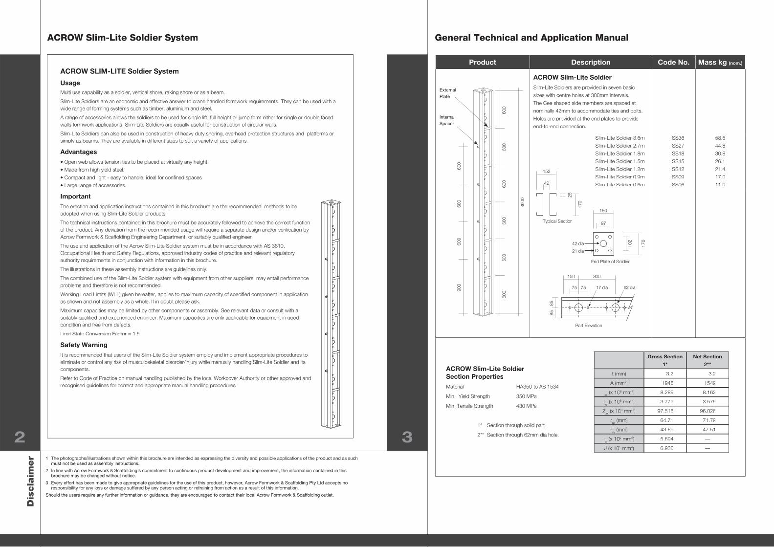
ACROW Slim-Lite SoldierSlim-Lite Soldiers are provided in seven basic
sizes with centre holes at 300mm intervals.
The Cee shaped side members are spaced at
nominally 42mm to accommodate ties and bolts.
Holes are provided at the end plates to provide
end-to-end connection.
Slim-Lite Soldier 3.6m
Slim-Lite Soldier 2.7m
Slim-Lite Soldier 1.8m
Slim-Lite Soldier 1.5m
Slim-Lite Soldier 1.2m
Slim-Lite Soldier 0.9m
Slim-Lite Soldier 0.6m
SS36
SS27
SS18
SS15
SS12
SS09
SS06
58.6
44.8
30.8
26.1
21.4
17.0
11.0
1 The photographs/illustrations shown within this brochure are intended as expressing the diversity and possible applications of the product and as such must not be used as assembly instructions.
2 In line with Acrow Formwork & Scaffolding’s commitment to continuous product development and improvement, the information contained in this brochure may be changed without notice.
3 Every effort has been made to give appropriate guidelines for the use of this product, however, Acrow Formwork & Scaffolding Pty Ltd accepts no responsibility for any loss or damage suffered by any person acting or refraining from action as a result of this information.
Should the users require any further information or guidance, they are encouraged to contact their local Acrow Formwork & Scaffolding outlet.
ACROW SLIM-LITE Soldier System
UsageMulti use capability as a soldier, vertical shore, raking shore or as a beam.
Slim-Lite Soldiers are an economic and effective answer to crane handled formwork requirements. They can be used with a wide range of forming systems such as timber, aluminium and steel.
A range of accessories allows the soldiers to be used for single lift, full height or jump form either for single or double faced walls formwork applications. Slim-Lite Soldiers are equally useful for construction of circular walls.
Slim-Lite Soldiers can also be used in construction of heavy duty shoring, overhead protection structures and platforms or simply as beams. They are available in different sizes to suit a variety of applications.
Advantages• Open web allows tension ties to be placed at virtually any height.
• Made from high yield steel.
• Compact and light - easy to handle, ideal for confi ned spaces.
• Large range of accessories.
ImportantThe erection and application instructions contained in this brochure are the recommended methods to be adopted when using Slim-Lite Soldier products.
The technical instructions contained in this brochure must be accurately followed to achieve the correct function of the product. Any deviation from the recommended usage will require a separate design and/or verifi cation by Acrow Formwork & Scaffolding Engineering Department, or suitably qualifi ed engineer.
The use and application of the Acrow Slim-Lite Soldier system must be in accordance with AS 3610, Occupational Health and Safety Regulations, approved industry codes of practice and relevant regulatory authority requirements in conjunction with information in this brochure.
The illustrations in these assembly instructions are guidelines only.
The combined use of the Slim-Lite Soldier system with equipment from other suppliers may entail performance problems and therefore is not recommended.
Working Load Limits (WLL) given hereafter, applies to maximum capacity of specifi ed component in application as shown and not assembly as a whole. If in doubt please ask.
Maximum capacities may be limited by other components or assembly. See relevant data or consult with a suitably qualifi ed and experienced engineer. Maximum capacities are only applicable for equipment in good condition and free from defects.
Limit State Conversion Factor = 1.5
Safety WarningIt is recommended that users of the Slim-Lite Soldier system employ and implement appropriate procedures to eliminate or control any risk of musculoskeletal disorder/injury while manually handling Slim-Lite Soldier and its components.
Refer to Code of Practice on manual handling published by the local Workcover Authority or other approved and recognised guidelines for correct and appropriate manual handling procedures.
Typical Section
End Plate of Soldier
Part Elevation
Gross Section
1*
Net Section
2**
t (mm) 3.2 3.2
A (mm2) 1946 1549
Ixx (x 106 mm4) 8.289 8.162
Iyyyy (x 106 mm4) 3.779 3.575
Zxx (x 103 mm3) 97.518 96.026
rxx (mm) 64.71 71.79
ryyyy (mm) 43.69 47.51
Iw (x 109 mm6) 5.694 —
J (x 103 mm4) 6.930 —
ACROW Slim-Lite SoldierSection PropertiesMaterial HA350 to AS 1534
Min. Yield Strength 350 MPa
Min. Tensile Strength 430 MPa
1* Section through solid part
2** Section through 62mm dia hole.
102
170
97
42 dia
21 dia
150
300150
75 75
8585
17 dia 62 dia
25
42
152
170
600
600
600
600
600
600
3600
600
600
600
900
External
Plate
Internal
Spacer
ACROW Slim-Lite Soldier System General Technical and Application Manual
4 5
Product Description Code No. Mass kg (nom.)
Slim-Lite Adjustable Plumbing BraceWhen walls are sloping and not vertical, then
the Adjustable Working Platform Bracket can be
fi xed to the Slim-Lite Soldier in conjunction with
the Adjustable Plumbing Brace using Universal
Locating Pins. They may also be used to provide
vertical alignment of small forms (the base must
be secured to the ground using suitable anchors
to resist the imposed loads and extra care must
be taken to resist uplift).
They are available in two types, Type 1 and
Type 2.
THTTDB 17.3
Slim-Lite Adjustable Plumbing Brace Type 1
Slim-Lite Adjustable Plumbing Brace Type 2SSPFA
SSAPB2
4.5
9.0
Universal Locating PinAllows a range of accessories to be secured to the
Slim-Lite Soldier. SSLPU 0.2
Connecting Bolts and NutsListed below are the recommended bolts and nuts
for use with the Slim-Lite Soldier System.
THTPT 90.0
M20 x 50mm long bolt
M20 x 100mm long bolt
M20 nut
M16 x 80mm long Grade 8.8 bolt
M16 nut, grade 8.8
SSHHBM50
SSHHBM20
SSNM20
SSHBM16-2
SSNM16
0.18
0.34
0.06
0.16
0.03
Slim-Lite Lifting LoopUsed for lifting Slim-Lite Soldier formwork
shutters by bolting to the top of the soldiers using
M20 nuts.
SSLL 1.0
Product Description Code No. Mass kg (nom.)
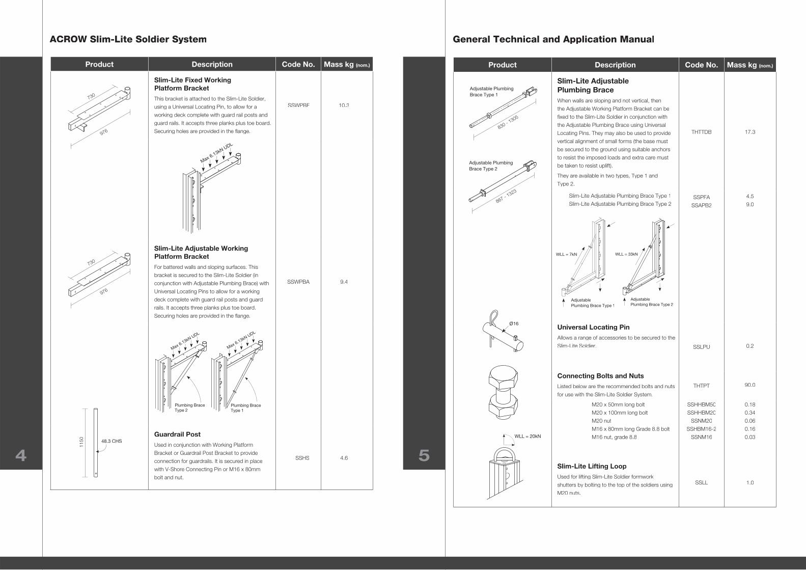
Slim-Lite Fixed Working Platform BracketThis bracket is attached to the Slim-Lite Soldier,
using a Universal Locating Pin, to allow for a
working deck complete with guard rail posts and
guard rails. It accepts three planks plus toe board.
Securing holes are provided in the fl ange.
SSWPBF 10.3
Slim-Lite Adjustable Working Platform BracketFor battered walls and sloping surfaces. This
bracket is secured to the Slim-Lite Soldier (in
conjunction with Adjustable Plumbing Brace) with
Universal Locating Pins to allow for a working
deck complete with guard rail posts and guard
rails. It accepts three planks plus toe board.
Securing holes are provided in the fl ange.
SSWPBA 9.4
Guardrail PostUsed in conjunction with Working Platform
Bracket or Guardrail Post Bracket to provide
connection for guardrails. It is secured in place
with V-Shore Connecting Pin or M16 x 80mm
bolt and nut.
SSHS 4.6
WLL = 7kN
Adjustable
Plumbing Brace Type 1
WLL = 33kN
Adjustable
Plumbing Brace Type 2
Adjustable Plumbing
Brace Type 1
830 - 1305
1150 48.3 CHS
Plumbing Brace
Type 2
Max 6.13kN UDL
867 - 1323
Adjustable Plumbing
Brace Type 2
730
976
730
976
Max 6.13kN UDL
WLL = 20kN
16
Plumbing Brace
Type 1 - @ 460 angle
Max 6.13kN UDL
ACROW Slim-Lite Soldier System General Technical and Application Manual
6 7
Product Description Code No. Mass kg (nom.)
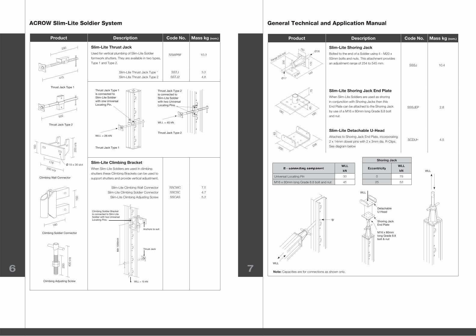
Slim-Lite Shoring JackBolted to the end of a Soldier using 4 - M20 x
50mm bolts and nuts. This attachment provides
an adjustment range of 254 to 545 mm.SSSJ 10.4
Slim-Lite Shoring Jack End PlateWhen Slim-Lite Soldiers are used as shoring
in conjunction with Shoring Jacks then this
End Plate can be attached to the Shoring Jack
by use of a M16 x 80mm long Grade 8.8 bolt
and nut.
SSSJEP 2.8
Slim-Lite Detachable U-HeadAttaches to Shoring Jack End Plate, incorporating
2 x 14mm dowel pins with 2 x 3mm dia. R-Clips.
See diagram below
SCDUH 4.5
Product Description Code No. Mass kg (nom.)
Slim-Lite Thrust JackUsed for vertical plumbing of Slim-Lite Soldier
formwork shutters. They are available in two types,
Type 1 and Type 2.
SSWPBF 10.3
Slim-Lite Thrust Jack Type 1
Slim-Lite Thrust Jack Type 2
SSTJ
SSTJ2
3.2
4.8
Slim-Lite Climbing BracketWhen Slim-Lite Soldiers are used in climbing
shutters these Climbing Brackets can be used to
support shutters and provide vertical adjustment.
Slim-Lite Climbing Wall Connector
Slim-Lite Climbing Soldier Connector
Slim-Lite Climbing Adjusting Screw
SSCWC
SSCSC
SSCAS
7.5
4.7
5.2
WLL
kN
Universal Locating Pin 33
M16 x 80mm long Grade 8.8 bolt and nut 45
Note: Capacities are for connections as shown only.
250
400
o/a
Climbing Adjusting Screw
Climbing Soldier Bracket
is connected to Slim-Lite
Soldier with two Universal
Locating Pins.
Min
1000m
m
Anchors to suit
Thrust Jack
WLL = 15 kN
Climbing Soldier Connector
150
180
178
250 o/a
150
200
o/a
18 x 36 slot
Climbing Wall Connector
Range 254-545
5450-291
150
17020
0
17
36
180180
7545
WLL
'B'
WLL
Detachable
U-Head
Shoring Jack
End Plate
M16 x 80mm
long Grade 8.8
bolt & nut
226200
83
Thrust Jack Type 1
is connected to
Slim-Lite Soldier
with one Universal
Locating Pin.
WLL = 26 kN
Thrust Jack Type 1
Thrust Jack Type 2
is connected to
Slim-Lite Soldier
with two Universal
Locating Pins.
WLL = 45 kN
Thrust Jack Type 2
415
290
Thrust Jack Type 1
502
Thrust Jack Type 2
Shoring Jack
EccentricityWLL
kN
0 79
25 53
WLL = 79kN
ACROW Slim-Lite Soldier System General Technical and Application Manual
8 9
Product Description Code No. Mass kg (nom.)
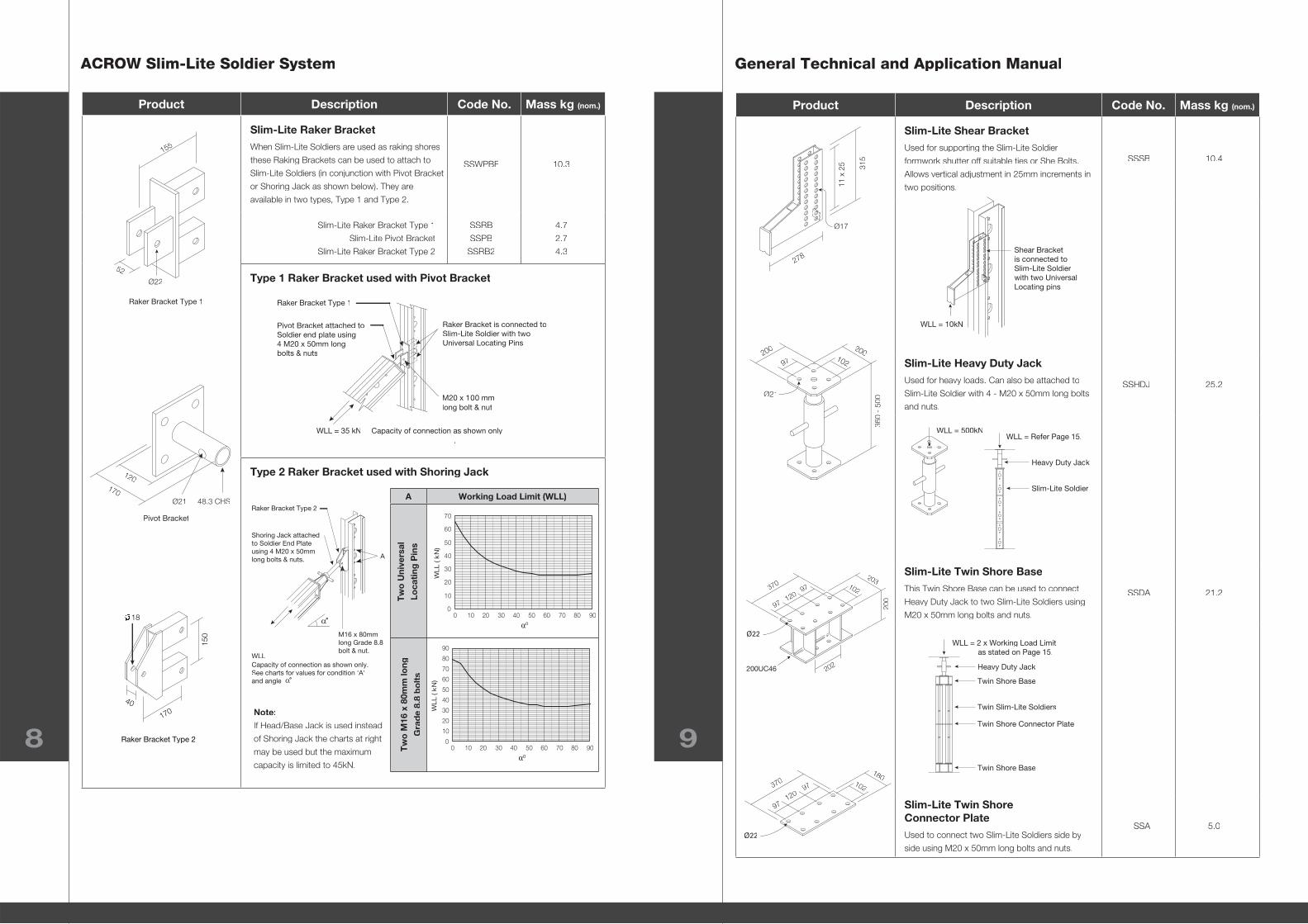
Slim-Lite Raker BracketWhen Slim-Lite Soldiers are used as raking shores
these Raking Brackets can be used to attach to
Slim-Lite Soldiers (in conjunction with Pivot Bracket
or Shoring Jack as shown below). They are
available in two types, Type 1 and Type 2.
SSWPBF 10.3
Slim-Lite Raker Bracket Type 1
Slim-Lite Pivot Bracket
Slim-Lite Raker Bracket Type 2
SSRB
SSPB
SSRB2
4.7
2.7
4.3
Type 1 Raker Bracket used with Pivot Bracket
Type 2 Raker Bracket used with Shoring Jack
Product Description Code No. Mass kg (nom.)
Slim-Lite Shear BracketUsed for supporting the Slim-Lite Soldier
formwork shutter off suitable ties or She Bolts.
Allows vertical adjustment in 25mm increments in
two positions.
SSSB 10.4
Slim-Lite Heavy Duty JackUsed for heavy loads. Can also be attached to
Slim-Lite Soldier with 4 - M20 x 50mm long bolts
and nuts.
SSHDJ 25.2
Slim-Lite Twin Shore BaseThis Twin Shore Base can be used to connect
Heavy Duty Jack to two Slim-Lite Soldiers using
M20 x 50mm long bolts and nuts.
SSDA 21.2
Slim-Lite Twin Shore Connector PlateUsed to connect two Slim-Lite Soldiers side by
side using M20 x 50mm long bolts and nuts.
SSA 5.0
Ø21
20020010297
360
- 50
0
WLL = 500kN
Ø21
120170
Pivot Bracket
48.3 CHS
WLL
Capacity of connection as shown only.
See charts for values for condition 'A'
and angle
Shoring Jack attached
to Soldier End Plate
using 4 M20 x 50mm
long bolts & nuts.
Raker Bracket Type 2
M16 x 80mm
long Grade 8.8
bolt & nut.
A
Note:
If Head/Base Jack is used instead
of Shoring Jack the charts at right
may be used but the maximum
capacity is limited to 45kN.
A Working Load Limit (WLL)
0
10
20
30
40
50
60
70
0 10 20 30 40 50 60 70 80 90
WL
L ( k
N)
0
0 10 20 30 40 50 60 70 80 90
WL
L ( k
N)
0
0
10
20
30
40
50
60
70
80
90
Tw
o M
16 x
80m
m lo
ng
Gra
de
8.8
bo
lts
Tw
o U
nive
rsal
Loca
ting
Pin
s
Raker Bracket Type 1
WLL = 35 kN Capacity of connection as shown only
.
M20 x 100 mm
long bolt & nut
Raker Bracket is connected to
Slim-Lite Soldier with two
Universal Locating Pins
Pivot Bracket attached to
Soldier end plate using
4 M20 x 50mm long
bolts & nuts
Raker Bracket Type 1
Ø22
155
52
Raker Bracket Type 2
150
170
40
18
Ø17
11 x
25 31
5
278
WLL = Refer Page 15.
Heavy Duty Jack
Slim-Lite Soldier
Shear Bracket
is connected to
Slim-Lite Soldier
with two Universal
Locating pins
WLL = 10kN
WLL = 2 x Working Load Limit
as stated on Page 15.
Twin Slim-Lite Soldiers
Twin Shore Base
Twin Shore Connector Plate
Heavy Duty Jack
Twin Shore Base
Ø22
202
370
97
97
120
200UC46
200
203102
Ø22
370
97
97
120
180102
ACROW Slim-Lite Soldier System General Technical and Application Manual
10 11
Product Description Code No. Mass kg (nom.)
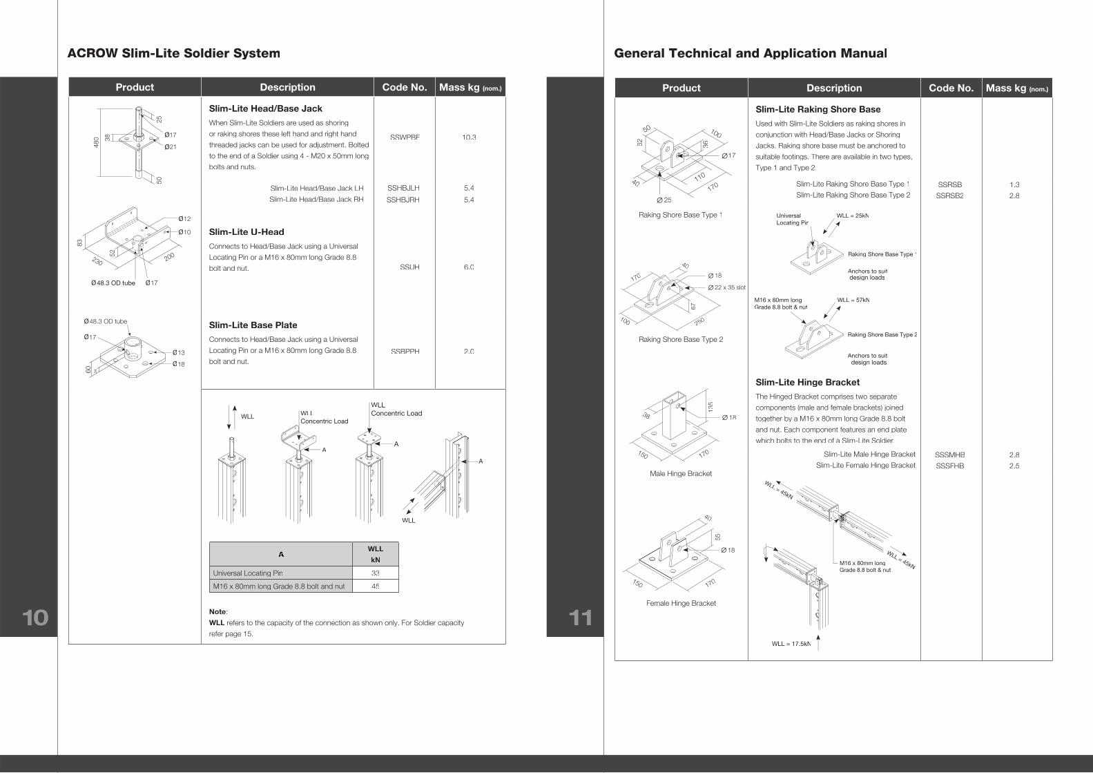
Slim-Lite Raking Shore BaseUsed with Slim-Lite Soldiers as raking shores in
conjunction with Head/Base Jacks or Shoring
Jacks. Raking shore base must be anchored to
suitable footings. There are available in two types,
Type 1 and Type 2.
Slim-Lite Raking Shore Base Type 1
Slim-Lite Raking Shore Base Type 2SSRSB
SSRSB2
1.3
2.8
Slim-Lite Hinge BracketThe Hinged Bracket comprises two separate
components (male and female brackets) joined
together by a M16 x 80mm long Grade 8.8 bolt
and nut. Each component features an end plate
which bolts to the end of a Slim-Lite Soldier.
Slim-Lite Male Hinge Bracket
Slim-Lite Female Hinge BracketSSSMHB
SSSFHB
2.8
2.5
Product Description Code No. Mass kg (nom.)
Slim-Lite Head/Base JackWhen Slim-Lite Soldiers are used as shoring
or raking shores these left hand and right hand
threaded jacks can be used for adjustment. Bolted
to the end of a Soldier using 4 - M20 x 50mm long
bolts and nuts.
SSWPBF 10.3
Slim-Lite Head/Base Jack LH
Slim-Lite Head/Base Jack RH
SSHBJLH
SSHBJRH
5.4
5.4
Slim-Lite U-HeadConnects to Head/Base Jack using a Universal
Locating Pin or a M16 x 80mm long Grade 8.8
bolt and nut. SSUH 6.0
Slim-Lite Base PlateConnects to Head/Base Jack using a Universal
Locating Pin or a M16 x 80mm long Grade 8.8
bolt and nut.SSBPPH 2.0
Note:
WLL refers to the capacity of the connection as shown only. For Soldier capacity
refer page 15.
WLL
kN
Universal Locating Pin 33
M16 x 80mm long Grade 8.8 bolt and nut 45
WLLWLL
Concentric Load
A
WLL
Concentric Load
A
WLL
A
18
40
65
170150
Female Hinge Bracket
Male Hinge Bracket
Raking Shore Base Type 1
Raking Shore Base Type 2
WLL = 45kN
WLL = 45kN
M16 x 80mm long
Grade 8.8 bolt & nut
WLL = 17.5kN
18
170150
38
135
100
40
3662
50
110
170
25
17
40
170
100 250
67
18
22 x 35 slot
Ø13
Ø17
Ø18
Ø48.3 OD tube
60 34
Ø21
Ø17
2550
38
480
Ø
Ø
Ø Ø
10
12
48.3 OD tube 17
200230
52
83
WLL = 25kN
Anchors to suit
Raking Shore Base Type 1
Universal
Locating Pin
design loads
WLL = 57kNM16 x 80mm long
Grade 8.8 bolt & nut
Raking Shore Base Type 2
Anchors to suit
design loads
ACROW Slim-Lite Soldier System General Technical and Application Manual
12 13
Product Description Code No. Mass kg (nom.)
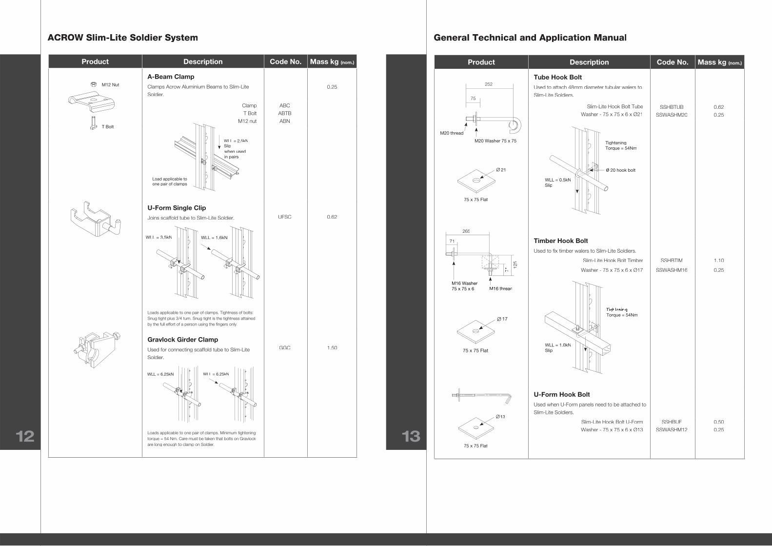
Tube Hook BoltUsed to attach 48mm diameter tubular walers to
Slim-Lite Soldiers.
Slim-Lite Hook Bolt Tube
Washer - 75 x 75 x 6 x Ø21SSHBTUB
SSWASHM20
0.62
0.25
Timber Hook BoltUsed to fi x timber walers to Slim-Lite Soldiers.
Slim-Lite Hook Bolt Timber
Washer - 75 x 75 x 6 x Ø17
SSHBTIM
SSWASHM16
1.10
0.25
U-Form Hook BoltUsed when U-Form panels need to be attached to
Slim-Lite Soldiers.
Slim-Lite Hook Bolt U-Form
Washer - 75 x 75 x 6 x Ø13
SSHBUF
SSWASHM12
0.50
0.25
Product Description Code No. Mass kg (nom.)
A-Beam ClampClamps Acrow Aluminium Beams to Slim-Lite
Soldier.0.25
Clamp
T Bolt
M12 nut
ABC
ABTB
ABN
U-Form Single ClipJoins scaffold tube to Slim-Lite Soldier.
Loads applicable to one pair of clamps. Tightness of bolts: Snug tight plus 3/4 turn. Snug tight is the tightness attained by the full effort of a person using the fi ngers only.
UFSC 0.62
Gravlock Girder ClampUsed for connecting scaffold tube to Slim-Lite
Soldier.
Loads applicable to one pair of clamps. Minimum tightening torque = 54 Nm. Care must be taken that bolts on Gravlock are long enough to clamp on Soldier.
GGC 1.50
WLL = 6.25kNWLL = 6.25kN
125
265
71
M16 threadM16 Washer
75 x 75 x 6
Torque = 54Nm
WLL = 1.0kN
Slip
75
252
M20 thread
M20 Washer 75 x 75 Tightening
Torque = 54Nm
WLL = 0.5kN
Slip
20 hook boltø
M12 Nut
T Bolt
WLL = 3.5kN WLL = 1.6kN
13
75 x 75 Flat
17
75 x 75 Flat
21
75 x 75 Flat
WLL = 2.5kN
Slip
Load applicable to
one pair of clamps
when used
in pairs
ACROW Slim-Lite Soldier System General Technical and Application Manual
14 15
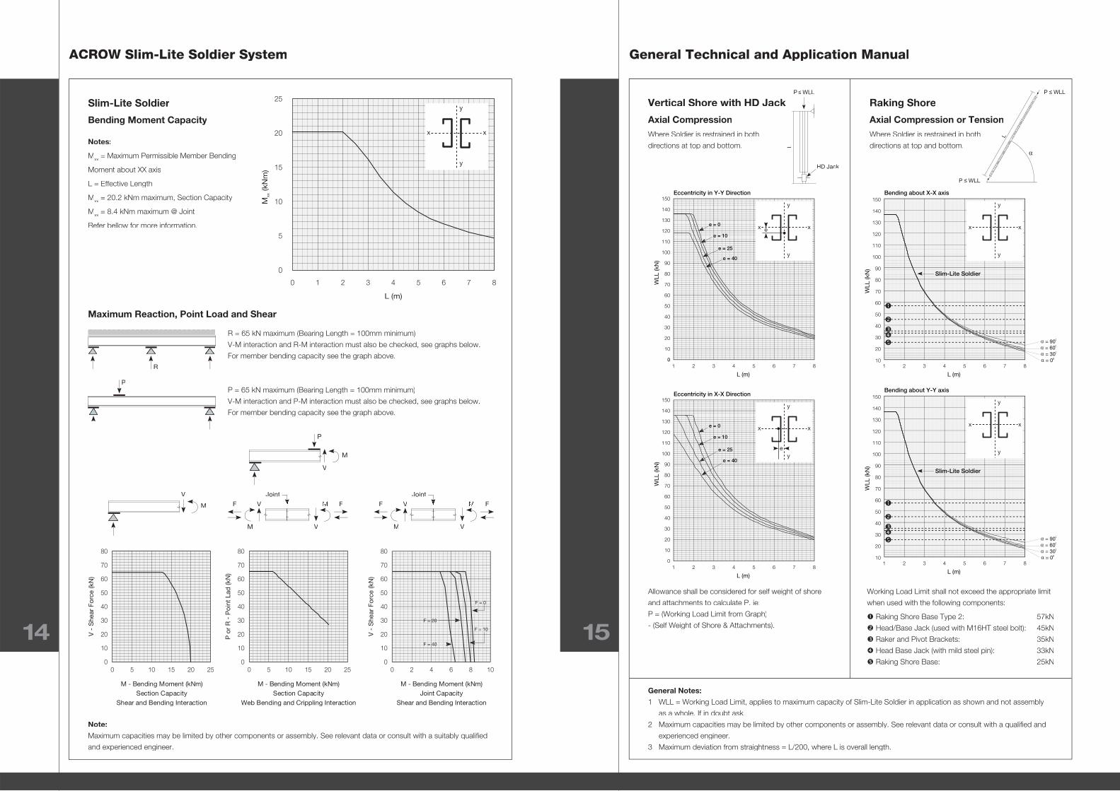
Slim-Lite Soldier
Bending Moment Capacity
Maximum Reaction, Point Load and Shear
Notes:
Mxx = Maximum Permissible Member Bending
Moment about XX axis
L = Effective Length
Mxx = 20.2 kNm maximum, Section Capacity
Mxx = 8.4 kNm maximum @ Joint
Refer bellow for more information.
R = 65 kN maximum (Bearing Length = 100mm minimum)
V-M interaction and R-M interaction must also be checked, see graphs below.
For member bending capacity see the graph above.
P = 65 kN maximum (Bearing Length = 100mm minimum)
V-M interaction and P-M interaction must also be checked, see graphs below.
For member bending capacity see the graph above.
Note:
Maximum capacities may be limited by other components or assembly. See relevant data or consult with a suitably qualifi ed
and experienced engineer.
Vertical Shore with HD Jack
Axial CompressionWhere Soldier is restrained in both
directions at top and bottom.
Allowance shall be considered for self weight of shore
and attachments to calculate P. ie:
P = (Working Load Limit from Graph)
- (Self Weight of Shore & Attachments).
Working Load Limit shall not exceed the appropriate limit
when used with the following components:
Raking Shore Base Type 2: 57kN
Head/Base Jack (used with M16HT steel bolt): 45kN
Raker and Pivot Brackets: 35kN
Head Base Jack (with mild steel pin): 33kN
Raking Shore Base: 25kN
General Notes:
1 WLL = Working Load Limit, applies to maximum capacity of Slim-Lite Soldier in application as shown and not assembly
as a whole. If in doubt ask.
2 Maximum capacities may be limited by other components or assembly. See relevant data or consult with a qualifi ed and
experienced engineer.
3 Maximum deviation from straightness = L/200, where L is overall length.
0 1 2 3 4 5 6 7 8
Mxx (kN
m)
L (m)
0
10
5
15
20
25y
y
x x
Section Capacity
Shear and Bending Interaction
M - Bending Moment (kNm)
V -
Sh
ear
Fo
rce (kN
)
0 5 10 15 20 250
10
20
30
40
50
60
70
80
Section Capacity
Web Bending and Crippling Interaction
M - Bending Moment (kNm)
P o
r R
- P
oin
t L
ad
(kN
)
0 5 10 15 20 250
10
20
30
40
50
60
70
80
Joint Capacity
Shear and Bending Interaction
M - Bending Moment (kNm)
V -
Sh
ear
Fo
rce (kN
)
0 2 4 6 8 100
10
20
30
40
50
60
70
80
F = 40
F = 20
F = 0
F = 10
1 2 3 4 5 6 7 8
10
0
20
30
40
50
60
70
80
90
100
110
120
130
140
150
L (m)
WL
L (kN
)
Eccentricity in Y-Y Direction
y
xx
y
e = 0
e = 10
e = 25
e = 40
e
1 2 3 4 5 6 7 8
10
0
20
30
40
50
60
70
80
90
100
110
120
130
140
150
L (m)
WL
L (kN
)
Eccentricity in X-X Direction
e = 0
e = 10
e = 25
e = 40
y
y
e
xx
1 2 3 4 5 6 7 810
20
30
40
50
60
70
80
90
100
110
120
130
140
150
Slim-Lite Soldier
Bending about X-X axis
L (m)
WL
L (kN
)
= 900
= 600
= 300
= 00
y
y
xx
1 2 3 4 5 6 7 810
20
30
40
50
60
70
80
90
100
110
120
130
140
150
Slim-Lite Soldier
Bending about Y-Y axis
L (m)
WL
L (kN
)
= 900
= 600
= 300
= 00
y
y
xx
R
V
M
V
V
Joint
F FV
M
M
M
P
V
V
V
Joint
F FV
M
M
P
L
P WLL
P WLL
Raking Shore
Axial Compression or TensionWhere Soldier is restrained in both
directions at top and bottom.L
HD Jack
P WLL

Up
dated
Octob
er 2011
Formwork
Scaffolding
Industrial & Mining Scaffolding
Phone: 1300 138 362or contact your business development manager.www.acrow.com.au
Contact