Embed Size (px)
Citation preview
ACTIVE CONTROL OF ACOUSTICALLY COUPLED PRESSURE OSCILLATION IN LEAN PREMIXED COMBUSTOR BY SECONDERY FUEL INJECTION
Hiroyuki Sato, and A. Koichi Hayashi
Aoyama Gakuin University 5-10-1 Fuchinobe, Sagamihara, Kanagawa 229-8558, Japan
and Masaru Ikame, Kazuyoshi Harumi, Takeyuki Kishi, Katsuhide Hiraoka, and Hideyuki Oka
National Maritime research Institute 6-38-1 Shinkawa, Mitaka, Tokyo 181-0004, Japan
Abstract This paper describes results of experiments on combustion control systems for the suppression of combustion oscillation. Two different control approaches are proposed. One is thermo-acoustic approach using a secondary flame, which emit a pressure oscillation like a speaker. The control system for the suppression of pressure oscillations consists of four secondary flames as an actuator, a microphone as a sensor, and a simple time-delay control as an algorithm. The control system applied to the resonance at 64 Hz of a combustor to reduce successfully it more than 10 dB. Another approach is fluid mechanical one using secondary injection and is expected to achieve more effective stabilization than the former. As a basic study for such control system, flow field analysis using PIV technique is carried out together with a proposal of active combustion control for the combustor with secondary injection jet.
1. Introduction
In the field of gas turbines, the premixed combustion is usually adopted as a means of low environmental load combustion. This combustion method, however, often brings combustion instabilities that narrow the operation range of gas turbine. Among the unstable combustion phenomena, the combustion oscillation with intense pressure waves has a practical significance, since the violent oscillations in the flow and mechanical vibrations of the system components cause even structural damage of the combustion system.
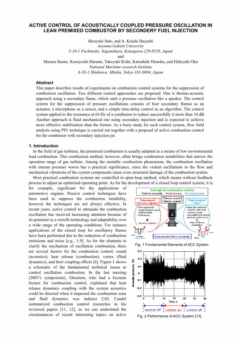
Most practical combustion systems are controlled in open-loop method, which means without feedback process to adjust an optimized operating point. As for the development of a closed loop control system, it is, for example, significant for the applications of automotive engines. Passive control techniques have been used to suppress the combustion instability, however the techniques are not always effective. In recent years, active control to attenuate the combustion oscillation has received increasing attention because of its potential as a retrofit technology and adaptability over a wide range of the operating conditions. For instance applications of the closed loop for oscillatory flames have been performed due to the reduction of combustion emissions and noise [e.g., 1-9]. As for the elements to clarify the mechanism of oscillation combustion, there are several factors for the combustion control; sound (acoustics), heat release (combustion), vortex (fluid dynamics), and their coupling effects [6]. Figure 1 shows a schematic of the fundamental technical issues to control oscillation combustion. In the last meeting (2003’s symposium), Ghoniem, who had a keynote lecture for combustion control, explained that heat release dynamics coupling with the system acoustics could be directed when it impacted the combustion zone and fluid dynamics was indirect [10]. Candel summarized combustion control researches in his reviewed papers [11, 12], so we can understand the circumstances of recent interesting topics on active
Fig. 1 Fundamental Elements of ACC System
Fig. 2 Performance of ACC System [13]
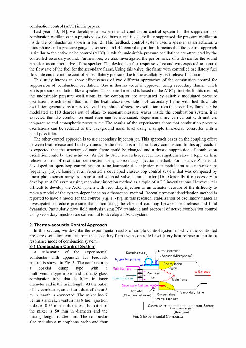
combustion control (ACC) in his papers. Last year [13, 14], we developed an experimental combustion control system for the suppression of
combustion oscillation in a premixed swirled burner and it successfully suppressed the pressure oscillation inside the combustor as shown in Fig. 2. This feedback control system used a speaker as an actuator, a microphone and a pressure gauge as sensors, and H2 control algorithm. It means that the control approach is similar to the active noise control (ANC) in which undesirable pressure oscillations are attenuated by the controlled secondary sound. Furthermore, we also investigated the performance of a device for the sound emission as an alternative of the speaker. The device is a fast response valve and was expected to control the flow rate of the fuel for the secondary flame. Using this valve, the flame with controlled oscillatory fuel flow rate could emit the controlled oscillatory pressure due to the oscillatory heat release fluctuation.
This study intends to show effectiveness of two different approaches of the combustion control for suppression of combustion oscillation. One is thermo-acoustic approach using secondary flame, which emits pressure oscillation like a speaker. This control method is based on the ANC principle. In this method, the undesirable pressure oscillations in the combustor are attenuated by suitably modulated pressure oscillation, which is emitted from the heat release oscillation of secondary flame with fuel flow rate oscillation generated by a piezo-valve. If the phase of pressure oscillation from the secondary flame can be modulated at 180 degrees out of phase to resonant pressure waves inside the combustion system, it is expected that the combustion oscillation can be attenuated. Experiments are carried out with ambient temperature and atmospheric pressure air. The results of the experiments show that combustion pressure oscillations can be reduced to the background noise level using a simple time-delay controller with a band-pass filter.
The other control approach is to use secondary injection jet. This approach bases on the coupling effect between heat release and fluid dynamics for the mechanism of oscillatory combustion. In this approach, it is expected that the structure of main flame could be changed and a drastic suppression of combustion oscillation could be also achieved. As for the ACC researches, recent investigations show a topic on heat release control of oscillation combustion using a secondary injection method. For instance Zinn et al. developed an open-loop control system using harmonic fuel injection rate modulation at a non-resonant frequency [15]. Ghoniem et al. reported a developed closed-loop control system that was composed by linear photo sensor array as a sensor and solenoid valve as an actuator [16]. Generally it is necessary to develop an ACC system using secondary injection method as a topic of ACC investigations. However it is difficult to develop the ACC system with secondary injection as an actuator because of the difficulty to make a model of the system dependence on a theoretical method. Recently system identification method is reported to have a model for the control [e.g. 17-19]. In this research, stabilization of oscillatory flames is investigated to reduce pressure fluctuation using the effect of coupling between heat release and fluid dynamics. Particularly flow field analysis using PIV technique and proposal of active combustion control using secondary injection are carried out to develop an ACC system. 2. Thermo-acoustic Control Approach
In this section, we describe the experimental results of simple control system in which the controlled pressure oscillation emitted from the secondary flame with controlled oscillatory heat release attenuates a resonance mode of combustion system. 2-1 Combustion Control System
A schematic of the experimental combustor with apparatus for feedback control is shown in Fig. 3. The combustor is a coaxial dump type with a multi-venturi-type mixer and a quartz glass combustion tube that is 0.1m in inner diameter and is 0.3 m in length. At the outlet of the combustor, an exhaust duct of about 5 m in length is connected. The mixer has 7 venturis and each venturi has 8 fuel injection holes of 0.75 mm in diameter. The outlet of the mixer is 50 mm in diameter and the mixing length is 266 mm. The combustor also includes a microphone probe and four
Secondary fuel gas
Main fuel gas
Combustion air
Controller
Sensor (Microphone)
Feed back signal(Pressure)
Control signal(Valve opening)
Secondary flame
Main flame
Actuator(Flow control valve)
Premixedgas
Recirculationregion
to Controller
from Sensor
N2 gas for purging
Damping tube
to Exhaust
Fig. 3 Experimental Combustor
fuel control valves for flow rate modulation of the secondary fuel. The secondary fuel is injected into the recirculation region of the combustion chamber through four injection nozzles on the dump plane and four secondary flames are held. Here, the secondary flames are diffusion ones, whereas the main flame is a premixed one.
In this project, the targeted combustor to be controlled is a methane-air premixed swirl-combustor. The combustor used in this system is a coaxial dump type and its fuel is a mixture of hydrogen and air. Usage of the combustor of different type from targeted one is not preferable, in general. However, the purpose of the experiments for this control system is to demonstrate the possibility of the control based on the ANC principle. In the experiments, the main flame is only the sound source and the secondary flames are acoustic devices to suppress pressure oscillations from the main sound source. Therefore, we assume that the demonstration could extend our knowledge under the condition that the fluid mechanical interaction between the main flame and secondary flames is not so significant.
The pressure fluctuations in the combustor are sensed with the microphone probe located on the dump plane, where the amplitudes of axial modes are significant. The probe consists of a microphone (Bruel & Kjaer, Series 4138), a pressure tube, and a damping tube. The microphone is flush-mount on the inner surface of the pressure tube with inner diameter of 4 mm. The damping tube is 20 m in length and 4 mm in inner diameter, which suppresses reflections of pressure waves and resonance in the pressure tube. The probe is continuously purged with nitrogen gas at flow rate of about 0.1 L/min to prevent condensation of the water vapor from the combustion chamber.
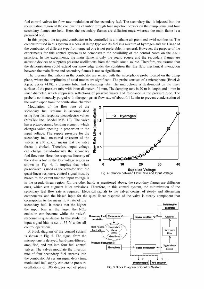
Modulation of the flow rate of the secondary fuel streams is accomplished using four fast response piezoelectric valves (MaxTek Inc., Model MV-112). The valve has a piezo-ceramic bending element, which changes valve opening in proportion to the input voltage. The supply pressure for the secondary fuel, measured upstream of the valves, is 250 kPa. It means that the valve throat is choked. Therefore, input voltage can change pseudo-linearly the secondary fuel flow rate. Here, the response linearity of the valve is lost in the low voltage region as shown in Fig. 4. It implies that when piezo-valve is used as the actuator with the quasi-linear response, control signal must be biased to the extent that the input voltage is in the pseudo-linear region. On the other hand, as mentioned above, the secondary flames are diffusion ones, which can augment NOx emissions. Therefore, in this control system, the minimization of the secondary fuel flow rate is required. Electrical signals to the valves consist of steady and alternating components, and the biased input for the quasi-linear response of the valve is steady component that corresponds to the mean flow rate of the secondary fuel. It means that the higher the input bias is, the larger the NOx emission can become while the valve's response is quasi-linear. In this study, the input signal bias is set at 35 V under all control operations.
l)/m
inl)/
min
0
0.5
1
1.5
2
0 10 20 30 4Supplied Voltage
Flow
Rat
e Li
ter(
norm
a Hydrogen
0
0.5
1
1.5
2
0 10 20 30 4Supplied Voltage
Flow
Rat
e Li
ter(
norm
a Hydrogen
Fig. 4 Relation between Flow Rate and Input Voltage
00
Microphone
Main flame
Piezo valve Bipolar amplifier
Signal conditioner
Band-passfilter
Signal delaydevise
Amplifier
Synchroscope FFT analyser
Multifunctiongenerator
Secondaryflame
Heat releasefluctuation
Secondary Fuelmodulation
Pressure fluctuation
Microphone
Main flameMain flame
Piezo valve Bipolar amplifier
Signal conditioner
Band-passfilter
Signal delaydevise
Amplifier
Synchroscope FFT analyser
Multifunctiongenerator
Secondaryflame
Secondaryflame
Heat releasefluctuation
Secondary Fuelmodulation
Pressure fluctuation
A block diagram of the control system is shown in Fig. 5. The signal from the microphone is delayed, band-pass-filtered, amplified, and put into four fuel control valves. The valves modulate the injection rate of four secondary fuel streams into the combustor. At certain signal delay time, modulated fuel supply can create pressure oscillations of 180 degrees out of phase Fig. 5 Block Diagram of Control System
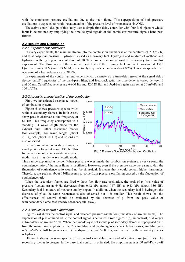
with the combustor pressure oscillations due to the main flame. This superposition of both pressure oscillations is expected to result the attenuation of the pressure level of resonance as in ANC.
The active control design of this study uses a simple time-delay controller with four fuel injectors whose input is determined by amplifying the time-delayed signals of the combustor pressure signals band-pass filtered. 2-2 Results and Discussion 2-2-1 Experimental conditions
In every experiments, the main air stream into the combustion chamber is at temperatures of 293±5 K, and at atmospheric pressure. Hydrogen is used as a primary fuel. Hydrogen and mixture of methane and hydrogen with hydrogen concentration of 20 % in mole fraction is used as secondary fuels in this experiment. The flow rate of the main air and that of the primary fuel are kept constant at 1500 L(normal)/min (NLM) and 158 NLM, respectively (equivalence ratio is about 0.25). This corresponds to an operation of a heat release rate of 28 kW.
In experiments of the control system, experimental parameters are time-delay given at the signal delay device, cutoff frequencies of the band-pass filter, and feed-back gain, the time-delay is varied between 0 and 60 ms. Cutoff frequencies are 6-600 Hz and 32-128 Hz, and feed-back gain was set at 50 mV/Pa and 100 mV/Pa. 2-2-2 Acoustic characteristics of the com
First, we inbustor
vestigated resonance modes of
sure spectra with/ w
of no secondary flames, a sm
combustion system. Figure 6 shows pres
ithout secondary flames. In both cases, sharp peak is observed at the frequency of 64 Hz. This frequency corresponds to a standing 3/4 wave length mode for the exhaust duct. Other resonance modes (for example, 1/4 wave length (about 20Hz), 5/4 (about 110Hz) and so on) are also observed.
In the case all peak is found at about 130Hz. This
frequency cannot be an acoustic resonance mode, since it is 6/4 wave length mode. This can be explained as below. When pressure waves inside the combustion system are very strong, the equivalence ratio of the main flame is oscillated. However, even if the pressure wave were sinusoidal, the fluctuation of equivalence ratio would not be sinusoidal. It means that it could contain higher harmonics. Therefore, the peak at about 130Hz seems to come from pressure oscillation caused by the fluctuation of equivalence ratio.
0.0001
0.0010
0.0100
0.1000
1.0000
0 100 200 300 400 500
Frequency (Hz)
Pre
ssur
e p
'rm
s (kP
a)
Without piloting
With piloting0.42kPa
0.13kPa Secondary fuel 0.8CH4+0.2H2
Fig. 6 Pressure Spectra of Combustion Oscillation
When the secondary flames are fired without fuel flow rate oscillation, the peak of p' (rms value of pressure fluctuation) at 64Hz decreases from 0.42 kPa (about 147 dB) to 0.13 kPa (about 136 dB). Secondary fuel is mixture of methane and hydrogen. In addition, when the secondary fuel is hydrogen, the decrease of p' at the same resonance is also observed but it is smaller. This result shows that the effectiveness of control should be evaluated by the decrease of p' from the peak value of with-secondary-flame case (steady secondary fuel flow). 2-2-3 Results of control experiments
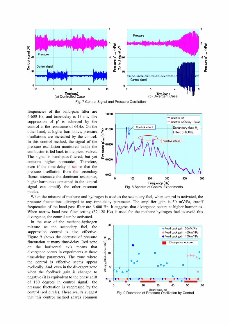
Figure 7 (a) shows the control signal and observed pressure oscillation (time delay of around 14 ms). The suppression of p' is attained while the control signal is activated. From figure 7 (b), in contrast, p’ diverges at time-delay of around 22 ms. When the time-delay is set so that p' of secondary flames is superposed on p' from the main flame in phase, while p' is amplified and the divergence occurs. In both cases, amplifier gain is 50 mV/Pa, cutoff frequencies of the band-pass filter are 6-600 Hz, and the fuel for the secondary flames is hydrogen.
Figure 8 shows pressure spectra of no control case (blue line) and of control case (red line). The secondary fuel is hydrogen. In the case that control is activated, the amplifier gain is 50 mV/Pa, cutoff
0
50
100
150
200
-10 -5 0 5 10
Time (sec.)
Con
trol
sig
nal (
V)
-3
-2
-1
0
1
Pre
ssur
e p'
rms (kP
a)
Control signal
Pressure
0
50
100
150
200
-10 -5 0 5 10
Time (sec.)
Con
trol
sig
nal (
V)
-3
-2
-1
0
1
Pre
ssur
e p'
rms (kP
a)
Control signal
Pressure
0
50
100
150
200
2 3 4 5
Time (sec.)
Con
trol
sig
nal (
V)
-6
-4
-2
0
2
Pre
ssur
e p'
rms (kP
a)
Control signal
Pressure
0
50
100
150
200
2 3 4 5
Time (sec.)
Con
trol
sig
nal (
V)
-6
-4
-2
0
2
Pre
ssur
e p'
rms (kP
a)
Control signal
Pressure
(b) Divergent Case (a) Controlled Case Fig. 7 Control Signal and Pressure Oscillation
frequencies of the band-pass filter are 6-600 Hz, and time-delay is 13 ms. The suppression of p' is achieved by the control at the resonance of 64Hz. On the other hand, at higher harmonics, pressure oscillations are increased by the control. In this control method, the signal of the pressure oscillation monitored inside the combustor is fed back to the piezo-valves. The signal is band-pass-filtered, but yet contains higher harmonics. Therefore, even if the time-delay is set so that the pressure oscillation from the secondary flames attenuate the dominant resonance, higher harmonics contained in the control signal can amplify the other resonant modes.
0.0010
0.0100
0.1000
1.0000
Pre
ssure
p' rm
s(k
Pa)
Control offControl on(delay 13ms)
Secondary fuel: H2
Filter: 6-600Hz
Negative effect
Control effect
0.0010
0.0100
0.1000
1.0000
Pre
ssure
p' rm
s(k
Pa)
Control offControl on(delay 13ms)
Secondary fuel: H2
Filter: 6-600Hz
Negative effect
Control effect
0.0001
0 100 200 300 400 500
Frequency (Hz)
0.0001
0 100 200 300 400 500
Frequency (Hz)Fig. 8 Spectra of Control Experiments
When the mixture of methane and hydrogen is used as the secondary fuel, when control is activated, the pressure fluctuations diverged at any time-delay parameter. The amplifier gain is 50 mV/Pa, cutoff frequencies of the band-pass filter are 6-600 Hz. It suggests that divergence occurs at higher harmonics. When narrow band-pass filter setting (32-128 Hz) is used for the methane-hydrogen fuel to avoid this divergence, the control can be activated.
In the case of the methane-hydrogen mixture as the secondary fuel, the suppression control is also effective. Figure 9 shows the decrease of pressure fluctuation at many time-delay. Red zone on the horizontal axis means that divergence occurs in experiments at these time-delay parameters. The zone where the control is effective seems appear cyclically. And, even in the divergent zone, when the feedback gain is changed to negative (it is equivalent to the phase shift of 180 degrees in control signal), the pressure fluctuation is suppressed by the control (red circle). These results suggest that this control method shares common
0
5
10
15
20
0 10 20 30 40 50 60
Delay time, ms
20Log
10(R
educ
tion
rat
io),
dB
Feed back gain 50mV/PaFeed back gain -50mV/PaFeed back gain 100mV/Pa
Divergence occured
Fig. 9 Decrease of Pressure Oscillation by Control
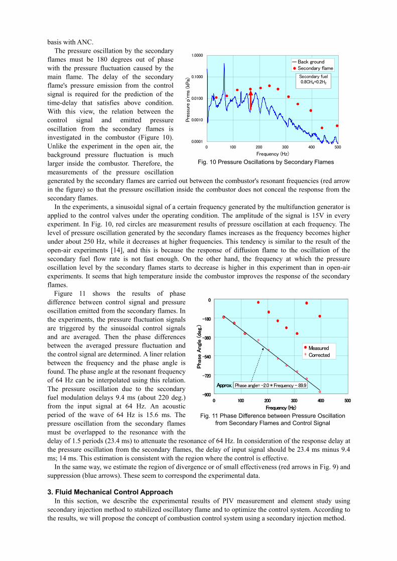
basis with ANC. The pressure oscillation by the secondary flames must be 180 degrees out of phase with the pressure fluctuation caused by the main flame. The delay of the secondary flame's pressure emission from the control signal is required for the prediction of the time-delay that satisfies above condition. With this view, the relation between the control signal and emitted pressure oscillation from the secondary flames is investigated in the combustor (Figure 10). Unlike the experiment in the open air, the background pressure fluctuation is much larger inside the combustor. Therefore, the measurements of the pressure oscillation generated by the secondary flames are carried out between the combustor's resonant frequencies (red arrow in the figure) so that the pressure oscillation inside the combustor does not conceal the response from the secondary flames.
0.0001
0.0010
0.0100
0.1000
1.0000
0 100 200 300 400 500
Frequency (Hz)
Pre
ssur
e p'
rms
(kPa)
Back groundSecondary flame
Secondary fuel0.8CH4+0.2H2
Fig. 10 Pressure Oscillations by Secondary Flames
In the experiments, a sinusoidal signal of a certain frequency generated by the multifunction generator is applied to the control valves under the operating condition. The amplitude of the signal is 15V in every experiment. In Fig. 10, red circles are measurement results of pressure oscillation at each frequency. The level of pressure oscillation generated by the secondary flames increases as the frequency becomes higher under about 250 Hz, while it decreases at higher frequencies. This tendency is similar to the result of the open-air experiments [14], and this is because the response of diffusion flame to the oscillation of the secondary fuel flow rate is not fast enough. On the other hand, the frequency at which the pressure oscillation level by the secondary flames starts to decrease is higher in this experiment than in open-air experiments. It seems that high temperature inside the combustor improves the response of the secondary flames.
Figure 11 shows the results of phase difference between control signal and pressure oscillation emitted from the secondary flames. In the experiments, the pressure fluctuation signals are triggered by the sinusoidal control signals and are averaged. Then the phase differences between the averaged pressure fluctuation and the control signal are determined. A liner relation between the frequency and the phase angle is found. The phase angle at the resonant frequency of 64 Hz can be interpolated using this relation. The pressure oscillation due to the secondary fuel modulation delays 9.4 ms (about 220 deg.) from the input signal at 64 Hz. An acoustic period of the wave of 64 Hz is 15.6 ms. The pressure oscillation from the secondary flames must be overlapped to the resonance with the delay of 1.5 periods (23.4 ms) to attenuate the resonance of 64 Hz. In consideration of the response delay at the pressure oscillation from the secondary flames, the delay of input signal should be 23.4 ms minus 9.4 ms; 14 ms. This estimation is consistent with the region where the control is effective.
-540
-360
-180
0
Phas
e A
ngl
e (de
g.)
MeasuredCorrected-540
-360
-180
0
Phas
e A
ngl
e (de
g.)
MeasuredCorrected
Phase angle= -2.0 * Frequency - 89.9
-900
-720
0 100 200 300 400 500
Frequency (Hz)
Approx. Phase angle= -2.0 * Frequency - 89.9
-900
-720
0 100 200 300 400 500
Frequency (Hz)
Approx.
Fig. 11 Phase Difference between Pressure Oscillation from Secondary Flames and Control Signal
In the same way, we estimate the region of divergence or of small effectiveness (red arrows in Fig. 9) and suppression (blue arrows). These seem to correspond the experimental data. 3. Fluid Mechanical Control Approach
In this section, we describe the experimental results of PIV measurement and element study using secondary injection method to stabilized oscillatory flame and to optimize the control system. According to the results, we will propose the concept of combustion control system using a secondary injection method.
3-1 Experimental setup and measurement system
P.C.P.C.
Dual head
Nd:YAG LASER
532[nm]
CCD CAM ERA
PC with DaVis
Air
CH4
Flow controller
Gas mixture unit
PC Particle
Combustor
100 mm
50 mm
M icrophoneFFT
analyzer
P.C.P.C.
P.C.P.C.
P.C.P.C.
Noise level
FFT Power spectrum
θ : Swirl Angleθ : Swirl Angle
30 mm
Swirler and
secondary injection nozzle
P.C.P.C.
Dual head
Nd:YAG LASER
532[nm]
CCD CAM ERA
PC with DaVis
Air
CH4
Flow controller
Gas mixture unit
PC Particle
Combustor
100 mm
50 mm
M icrophoneM icrophoneFFT
analyzer
P.C.P.C.
P.C.P.C.
P.C.P.C.
Noise level
FFT Power spectrum
θ : Swirl Angleθ : Swirl Angle
30 mm
θ : Swirl Angleθ : Swirl Angle
30 mm
Swirler and
secondary injection nozzle
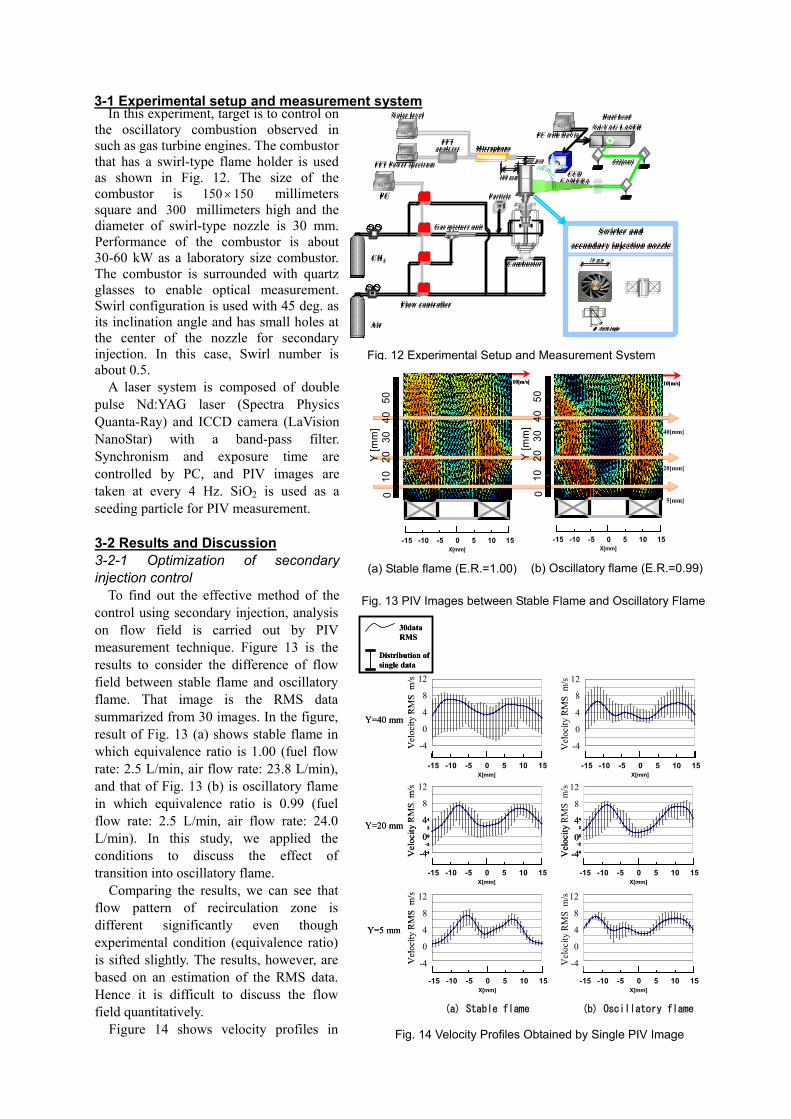
In this experiment, target is to control on the oscillatory combustion observed in such as gas turbine engines. The combustor that has a swirl-type flame holder is used as shown in Fig. 12. The size of the combustor is 150150 × msquare and 300 millimet high and the diameter of swirl-type nozzle is 30 mm. Performance of the combustor is about 30-60 kW as a laboratory size combustor. The combustor is surrounded with quartz glasses to enable optical measurement. Swirl configuration is used with 45 deg. as its inclination angle and has small holes at the center of the nozzle for secondary injection. In this case, Swirl number is about 0.5.
illimeters ers
Fig. 12 Experimental Setup and Measurement System
A laser system is composed of double pulse Nd:YAG laser (Spectra Physics Quanta-Ray) and ICCD camera (LaVision NanoStar) with a band-pass filter. Synchronism and exposure time are controlled by PC, and PIV images are taken at every 4 Hz. SiO2 is used as a seeding particle for PIV measurement. 3-2 Results and Discussion 3-2-1 Optimization of secondary injection control
To find out the effective method of the control using secondary injection, analysis on flow field is carried out by PIV measurement technique. Figure 13 is the results to consider the difference of flow field between stable flame and oscillatory flame. That image is the RMS data summarized from 30 images. In the figure, result of Fig. 13 (a) shows stable flame in which equivalence ratio is 1.00 (fuel flow rate: 2.5 L/min, air flow rate: 23.8 L/min), and that of Fig. 13 (b) is oscillatory flame in which equivalence ratio is 0.99 (fuel flow rate: 2.5 L/min, air flow rate: 24.0 L/min). In this study, we applied the conditions to discuss the effect of transition into oscillatory flame.
Comparing the results, we can see that flow pattern of recirculation zone is different significantly even though experimental condition (equivalence ratio) is sifted slightly. The results, however, are based on an estimation of the RMS data. Hence it is difficult to discuss the flow field quantitatively.
Y [m
m]
0
1030
4020
50
Y [m
m]
0
1030
4020
50
-4
-2
0
2
4
6
8
10
12
-4
-2
0
2
4
6
8
10
12
-15 -10 -5 0 5 10 15X[mm]
-15 -10 -5 0 5 10 15X[mm]
-15 -10 -5 0 5 10 15X[mm]
-15 -10 -5 0 5 10 15X[mm]
Y=40 mm
12
8
4
0
-4
12
8
4
0
-4Vel
ocity
RM
S m
/s
Vel
ocity
RM
S m
/s
-4
-2
0
2
4
6
8
10
12
-4
-2
0
2
4
6
8
10
12
-15 -10 -5 0 5 10 15X[mm]
-15 -10 -5 0 5 10 15X[mm]
-15 -10 -5 0 5 10 15X[mm]
-15 -10 -5 0 5 10 15X[mm]
Y=40 mm
12
8
4
0
-4
12
8
4
0
-4Vel
ocity
RM
S m
/s
Vel
ocity
RM
S m
/s
6
8
10
12
6
8
10
1212
8
12
8
RM
S m
/s
RM
S m
/s
6
8
10
12
6
8
10
1212
8
12
8
RM
S m
/s
RM
S m
/s
Distribution of single data
30data RMS
Distribution of single data
30data RMS
40[mm]
20[mm]
5[mm]
-15 -10 -5 0 5 10 15X[mm]
-15 -10 -5 0 5 10 15X[mm]
-15 -10 -5 0 5 10 15X[mm]
-15 -10 -5 0 5 10 15X[mm]
10[m/s]10[m/s] 10[m/s]10[m/s]
(a) Stable flame (b) Oscillatory flame
-4
-2
0
2
4
-4
-2
0
2
44
0
-4
-15 -10 -5 0 5 10 15X[mm]
-15 -10 -5 0 5 10 15X[mm]
-15 -10 -5 0 5 10 15X[mm]
-15 -10 -5 0 5 10 15X[mm]
Y=20 mm 4
0
-4Vel
ocity
Vel
ocity
-4
-2
0
2
4
-4
-2
0
2
44
0
-4
-15 -10 -5 0 5 10 15X[mm]
-15 -10 -5 0 5 10 15X[mm]
-15 -10 -5 0 5 10 15X[mm]
-15 -10 -5 0 5 10 15X[mm]
Y=20 mm 4
0
-4Vel
ocity
Vel
ocity
-4
-2
0
2
4
6
8
10
12
-4
-2
0
2
4
6
8
10
12
-15 -10 -5 0 5 10 15X[mm]
-15 -10 -5 0 5 10 15X[mm]
-15 -10 -5 0 5 10 15X[mm]
-15 -10 -5 0 5 10 15X[mm]
Y=5 mm
12
8
4
0
-4
12
8
4
0
-4Vel
ocity
RM
S m
/s
Vel
ocity
RM
S m
/s
-4
-2
0
2
4
6
8
10
12
-4
-2
0
2
4
6
8
10
12
-15 -10 -5 0 5 10 15X[mm]
-15 -10 -5 0 5 10 15X[mm]
-15 -10 -5 0 5 10 15X[mm]
-15 -10 -5 0 5 10 15X[mm]
Y=5 mm
12
8
4
0
-4
12
8
4
0
-4Vel
ocity
RM
S m
/s
Vel
ocity
RM
S m
/s
Fig. 13 PIV Images between Stable Flame and Oscillatory Flame
(b) Oscillatory flame (E.R.=0.99)(a) Stable flame (E.R.=1.00)
Figure 14 shows velocity profiles in Fig. 14 Velocity Profiles Obtained by Single PIV Image
various vertical positions (Y=5, 20, 40 mm). In the figure, solid line implies RMS result of 30 images and vertical at each x-axis describes the range of data obtained by single PIV image. Fig. 14 (a) is the series of results obtained in stable flame and Fig. 14 (b) is that of oscillatory flame.
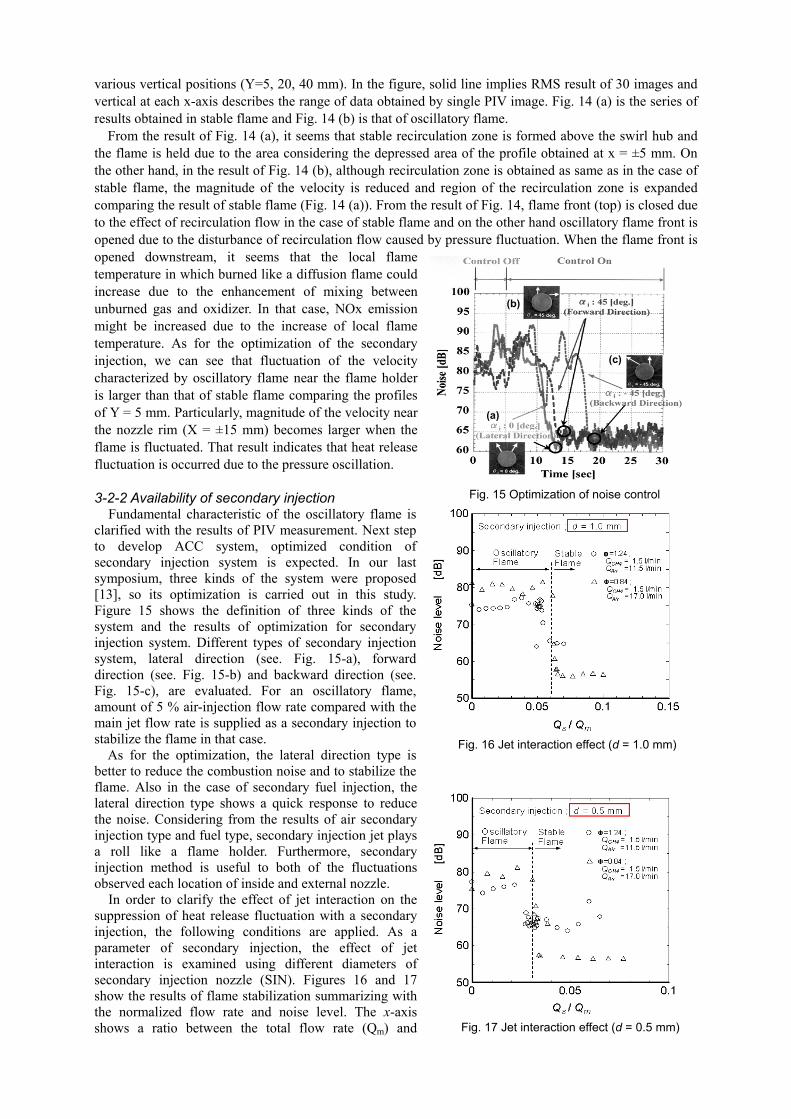
From the result of Fig. 14 (a), it seems that stable recirculation zone is formed above the swirl hub and the flame is held due to the area considering the depressed area of the profile obtained at x = ±5 mm. On the other hand, in the result of Fig. 14 (b), although recirculation zone is obtained as same as in the case of stable flame, the magnitude of the velocity is reduced and region of the recirculation zone is expanded comparing the result of stable flame (Fig. 14 (a)). From the result of Fig. 14, flame front (top) is closed due to the effect of recirculation flow in the case of stable flame and on the other hand oscillatory flame front is opened due to the disturbance of recirculation flow caused by pressure fluctuation. When the flame front is opened downstream, it seems that the local flame temperature in which burned like a diffusion flame could increase due to the enhancement of mixing between unburned gas and oxidizer. In that case, NOx emission might be increased due to the increase of local flame temperature. As for the optimization of the secondary injection, we can see that fluctuation of the velocity characterized by oscillatory flame near the flame holder is larger than that of stable flame comparing the profiles of Y = 5 mm. Particularly, magnitude of the velocity near the nozzle rim (X = ±15 mm) becomes larger when the flame is fluctuated. That result indicates that heat release fluctuation is occurred due to the pressure oscillation.
(c)
(b)
(a)
Fig. 15 Optimization of noise control 3-2-2 Availability of secondary injection
Fundamental characteristic of the oscillatory flame is clarified with the results of PIV measurement. Next step to develop ACC system, optimized condition of secondary injection system is expected. In our last symposium, three kinds of the system were proposed [13], so its optimization is carried out in this study. Figure 15 shows the definition of three kinds of the system and the results of optimization for secondary injection system. Different types of secondary injection system, lateral direction (see. Fig. 15-a), forward direction (see. Fig. 15-b) and backward direction (see. Fig. 15-c), are evaluated. For an oscillatory flame, amount of 5 % air-injection flow rate compared with the main jet flow rate is supplied as a secondary injection to stabilize the flame in that case. Fig. 16 Jet interaction effect (d = 1.0 mm)
As for the optimization, the lateral direction type is better to reduce the combustion noise and to stabilize the flame. Also in the case of secondary fuel injection, the lateral direction type shows a quick response to reduce the noise. Considering from the results of air secondary injection type and fuel type, secondary injection jet plays a roll like a flame holder. Furthermore, secondary injection method is useful to both of the fluctuations observed each location of inside and external nozzle.
Fig. 17 Jet interaction effect (d = 0.5 mm)
In order to clarify the effect of jet interaction on the suppression of heat release fluctuation with a secondary injection, the following conditions are applied. As a parameter of secondary injection, the effect of jet interaction is examined using different diameters of secondary injection nozzle (SIN). Figures 16 and 17 show the results of flame stabilization summarizing with the normalized flow rate and noise level. The x-axis shows a ratio between the total flow rate (Qm) and
secondary flow rate (Qs). In Fig. 16, diameter of the SIN is 1.0 millimeter, and that in Fig. 17 is 0.5 millimeter. According to an increase in the flow ratio, the noise level is decreased and the level achieves into the amount of background noise as shown in Figs. 16 and 17. Comparing the results, it is better choice to use a small-hole nozzle such as 0.5 millimeters diameter because oscillatory flames are stabilized with a bit of secondary fuel flow rate. In the case of Fig. 16, about 6 % secondary flow rate is necessary to reduce the combustion noise. On the other hand, the secondary flow rate is almost half (Qs / Qm = 3%) using a small hole of secondary nozzles (see. Fig. 17). The result indicates jet interaction is an effective way to control the oscillatory flame. Furthermore, the parameter of secondary flow rate per total flow rate is useful to control flow rate of secondary injection against the total flow rate. 3-2-3 Concept to develop ACC system using a secondary injection method
Recently development of ACC system using secondary injection method is extensively studied. However, we have a problem to find fast driving quick valve as an actuator for secondary injection control. In laboratory size investigations, most is carried out with the condition of low-frequency mode because the guarantee of developed control system is improved within a performance of secondary injection actuator (with an order of some hundred frequency). Indeed, oscillatory combustion observed in a gas turbine combustor has many different fluctuation modes over a wide rage of oscillatory frequency. In that case, it is difficult to determine the target to reduce distinguished frequency. Hence there is a necessity to develop a multi-used ACC system to adjust the change of oscillatory mode.
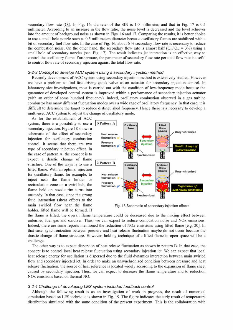
As for the establishment of ACC system, there is a possibility to use a secondary injection. Figure 18 shows a schematic of the effect of secondary injection for oscillatory combustion control. It seems that there are two type of secondary injection effect. In the case of pattern A, the concept is to expect a drastic change of flame structure. One of the ways is to use a lifted flame. With an optimal injection for oscillatory flame, for example, to inject near the flame holder or recirculation zone on a swirl hub, the flame held on nozzle rim turns into unsteady. In that case, since the strong fluid interaction (shear effect) to the main swirled flow near the flame holder, lifted flame will be formed. If the flame is lifted, the overall flame temperature could be decreased due to the mixing effect between unburned fuel gas and oxidizer. Thus, we can expect to reduce combustion noise and NOx emissions. Indeed, there are some reports mentioned the reduction of NOx emissions using lifted flame [e.g. 20]. In that case, synchronization between pressure and heat release fluctuation maybe do not occur because the drastic change of flame structure. However, holding technique of a lifted flame in open space will be a challenge.
Fig. 18 Schematic of secondary injection effects
The other way is to expect dispersion of heat release fluctuation as shown in pattern B. In that case, the concept is to control local heat release fluctuation using secondary injection jet. We can expect that local heat release energy for oscillation is dispersed due to the fluid dynamics interaction between main swirled flow and secondary injected jet. In order to make an unsynchronized condition between pressure and heat release fluctuation, the source of heat reference is located widely according to the expansion of flame sheet caused by secondary injection. Thus, we can expect to decrease the flame temperature and to reduction NOx emissions based on thermal NO. 3-2-4 Challenge of developing LES system included feedback control
Although the following result is as an investigation of work in progress, the result of numerical simulation based on LES technique is shown in Fig. 19. The figure indicates the early result of temperature distribution simulated with the same condition of the present experiment. This is the collaboration with
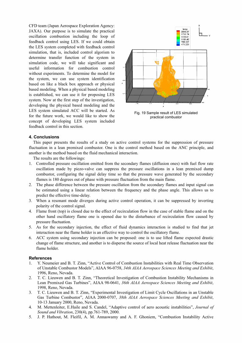
CFD team (Japan Aerospace Exploration Agency: JAXA). Our purpose is to simulate the practical oscillation combustion including the loop of feedback control using LES. If we could obtain the LES system completed with feedback control simulation, that is, included control algorism to determine transfer function of the system in simulation code, we will take significant and useful information for combustion control without experiments. To determine the model for the system, we can use system identification based on like a black box approach or physical based modeling. When a physical based modeling is established, we can use it for proposing LES system. Now at the first step of the investigation, developing the physical based modeling and the LES system simulated ACC will be started. As for the future work, we would like to show the concept of developing LES system included feedback control in this section.
Fig. 19 Sample result of LES simulated practical combustor
4. Conclusions
This paper presents the results of a study on active control systems for the suppression of pressure fluctuation in a lean premixed combustor. One is the control method based on the ANC principle, and another is the method based on the fluid mechanical interaction.
The results are the followings: 1. Controlled pressure oscillation emitted from the secondary flames (diffusion ones) with fuel flow rate
oscillation made by piezo-valve can suppress the pressure oscillations in a lean premixed dump combustor, configuring the signal delay time so that the pressure wave generated by the secondary flames is 180 degrees out of phase with pressure fluctuation from the main flame.
2. The phase difference between the pressure oscillation from the secondary flames and input signal can be estimated using a linear relation between the frequency and the phase angle. This allows us to predict the effective time-delay.
3. When a resonant mode diverges during active control operation, it can be suppressed by inverting polarity of the control signal.
4. Flame front (top) is closed due to the effect of recirculation flow in the case of stable flame and on the other hand oscillatory flame one is opened due to the disturbance of recirculation flow caused by pressure fluctuation.
5. As for the secondary injection, the effect of fluid dynamics interaction is studied to find that jet interaction near the flame holder is an effective way to control the oscillatory flame.
6. ACC system using secondary injection can be proposed: one is to use lifted flame expected drastic change of flame structure, and another is to disperse the source of local heat release fluctuation near the flame holder.
References 1. Y. Neumeier and B. T. Zinn, “Active Control of Combustion Instabilities with Real Time Observation
of Unstable Combustor Models”, AIAA 96-0758, 34th AIAA Aerospace Sciences Meeting and Exhibit, 1996, Reno, Nevada.
2. T. C. Lieuwen and B. T. Zinn, “Theoretical Investigation of Combustion Instability Mechanisms in Lean Premixed Gas Turbines”, AIAA 98-0641, 36th AIAA Aerospace Sciences Meeting and Exhibit, 1998, Reno, Nevada.
3. T. C. Lieuwen and B. T. Zinn, “Experimental Investigation of Limit Cycle Oscillations in an Unstable Gas Turbine Combustor”, AIAA 2000-0707, 38th AIAA Aerospace Sciences Meeting and Exhibit, 10-13 January 2000, Reno, Nevada.
4. M. Mettenleiter, E.Haile and S. Candel, “Adaptive control of aero acoustic instabilities”, Journal of Sound and Vibration, 230(4), pp.761-789, 2000.
5. J. P. Hathout, M. Fleifil, A. M. Annaswamy and A. F. Ghoniem, “Combustion Instability Active
Control Using Periodic Fuel Injection”, Journal of Propulsion and Power, vol. 18, no. 2, pp. 390, 2002.
6. A. M. Annaswamy and A. F. Ghoniem, “Active Control of Combustion Instability: Theory and Practice”, IEEE Control Syst. Mag., Vol.22, No.6, pp.37-54, 2002.
7. S. Park, A. M. Annaswamy and A. F. Ghoniem, “A Model-Based Self-tuning Controller for Kinetically Controlled Combustion Instability”, Proc. Am. Control Conf., Vol.2002, No.Vol.2, pp.1597-1602, 2002.
8. J. P. Hathout, M. Fleifil, A. M. Annaswamy and A. F. Ghoniem, “Combustion Instability Active Control Using Periodic Fuel Injection”, J. Propul. Power, Vol.18, No.2, pp.390-399, 2002.
9. J. P. Hathout, M. Fleifil, A. M. Annaswamy and A. F. Ghoniem, “Role of Actuation in Combustion Control”, Combust. Sci. Technol., Vol.167, pp.57-82, 2001.
10. A. F. Ghoniem, and A. M. Annaswamy, “Model-Based Active Control of Combustion, Recent Developments and Implementations”, Proc. 4th Symp. Smart Control of Turbulence, pp.61-79, 2003.
11. N. Docquier and S. Candel, “Combustion Control and Sensors: A Review”, Prog. Energy Combust. Sci. 28:107-150, 2002.
12. S. Candel, “Combustion Dynamics and Control: Progress and Challenges”, Proc. Combust. Inst.: 29, pp. 1-25, 2002.
13. Hayashi, A. K., Sato, H., Endo, T., Yasunami, Y., Yoshimi, S., Ogawa, S., Ikame, M., Kishi, T., Hiraoka, K., Harumi, K., and Oka, H., “Analysis of Unstable Phenomena in Premixed Flame Burners and their Active Control”, Proc. 4th Symp. Smart Control of Turbulence, pp.173-182, 2003.
14. K. Harumi et al., “Sound Emission from Laminar Diffusion Flame with Controlled Oscillatory Fuel Flow”, Proc. IGTC'03 Tokyo, TS-148, 2003.
15. E. Lubarsky, D. Shcherbik, A. Bibik, and B. T. Zinn, “Open Loop Control of Severe Combustion Instability by Fuel Flow Modulation at Non Resonant Frequencies”, AIAA 2004-0634, 42nd AIAA Aerospace Sciences Meeting and Exhibit, 5-8 January 2004, Reno, Nevada.
16. S. Park, A. Wachsman, A. M. Annaswamy, and A. F. Ghoniem, “Experimantal Study of POD-based Control for Combustion Instability Using a Linear Photodiode Array”, AIAA 2004-0639, 42nd AIAA Aerospace Sciences Meeting and Exhibit, 5-8 January 2004, Reno, Nevada.
17. S. Murugappan, S. Park, A. M. Annaswamy, A. F. Ghoniem, S. Acharya and D. C. Allgood, “Optimal Control of a Swirl Stabilized Spray Combustion Using System Identification Approach”, AIAA 2001-0779, 39th AIAA Aerospace Sciences Meeting and Exhibit, 8-11 January 2001, Reno, Nevada.
18. I. Kajiwara, M. Fukuda, and H. Shimojima, “Modeling and Active Noise Control of One-Dimensional Duct Based on Model Analysis and LMI”, JSME Journal Series C, vol. 64, no. 621, pp. 1668-1675, 1997.
19. H. Shimojima, Y. Matsunaga, S. Koike, and I. Kajiwara, “Feedback Active Noise Control with Multiple Control Sources based on Modal Analysis”, JSME Journal Series C, vol. 65, no.633, pp.1849-1856, 1998.
20. J. Chomiak, and A. Karlsson, “Flame Liftoff in Diesel Sprays”, Proc. Combust. Inst.: 26, pp. 2557-2564, 1996.