Embed Size (px)
Citation preview
1
Abstract— EMI filters for automotive motor drives must achieve stringent EMI specifications while meeting tight cost constraints. This paper explores the use of low-cost active circuitry to suppress motor drive emissions, thus reducing passive filtration requirements. Challenges to the use of active EMI filters in this application are outlined, and means for addressing these challenges are presented. A voltage sense, current drive active filter is developed that greatly enhances the performance of filter capacitors. The proposed approach is applied to an input filter for an automotive electro-hydraulic power steering pump drive. Experimental results are presented that demonstrate the feasibility and high performance of this approach and illustrate its advantages over conventional filter designs. Index Terms—EMI Filter, Active EMI Filter, Active Ripple Filter
I. INTRODUCTION
ulse-width modulated (PWM) motor drives are becoming widely used in automotive applications due to their high performance and efficiency. One drawback of such drives
is that they generate ripple. Stringent EMI specifications limit the maximum amount of ripple allowed. Therefore, PWM converters require input filters that provide substantial attenuation at EMI frequencies (e.g., >150 kHz). These filters can prove to be quite large and costly. Typically, input EMI filters utilize capacitors to provide a low impedance shunt path for high-frequency currents. Such capacitors must be able to shunt current over a wide frequency range. To achieve this, various types of capacitors are placed in parallel. Large-capacitance electrolytic capacitors are used to shunt lower frequencies and provide voltage holdup. For mid-range frequencies, smaller tantalum or ceramic capacitors are employed. Small ceramic capacitors are used for high EMI frequencies. The relative cost per capacitance is typically higher for capacitors that perform better at higher frequencies. Large-valued electrolytics are used because of their low cost,
high energy storage densities, and high ripple current capabilities, but they have poor high-frequency performance. On the other hand, ceramic capacitors have excellent high frequency performance, but are used sparingly due to cost.
An alternative to the conventional passive filtering approach is to use a hybrid passive/active filter [2-13]. In this approach, a reduced passive filter is coupled with an active electronic circuit to attenuate the ripple. The passive filter serves to limit the ripple to a level manageable by the active circuit, and to attenuate ripple components that fall beyond the bandwidth of the active circuit. The active filter circuit cancels or suppresses the low frequency ripple components that are most difficult to attenuate with a passive low-pass filter, thus easing the requirements on the passive filter. Structurally, an active ripple filter comprises a sensor (current or voltage), a linear amplifier, and drive circuit (current or voltage) configured to cancel or suppress ripple components in the passive filter output. This approach can permit a significant reduction in the passive filter cost.
This paper focuses on the application of active filtering techniques to input filters of pulse-width modulated (PWM) motor drives. As a design example, this paper focuses on the design of an input filter for an automotive electro-hydraulic power steering (EHPS) pump drive. Section II presents an analysis of a typical passive EMI filter for this application. This passive filter will serve as a benchmark for the active filter in terms of cost and performance. Section III will illustrate the primary design constraints of applying active filters to PWM motor drives. Section IV gives an overview of active filter techniques for input filters. Section V will explore an active filter design for this application. Section VI will present experimental results, and section VII concludes the paper.
II. PASSIVE FILTER CHARACTERISTICS
To illustrate the tradeoffs in filtering for PWM motor drives, this paper considers an input EMI filter for the PWM inverter in an EHPS pump motor drive. This application uses an inverter to convert the 14V DC voltage into three phase AC to
Active EMI Filters for Automotive Motor Drives Albert C. Chow David J. Perreault
Laboratory for Electromagnetic and Electronic Systems
Massachusetts Institute of Technology
M.I.T. Rm. 10-039 Cambridge, MA 02139
(617) 258-6038 FAX: (617) 258-6774
P
2
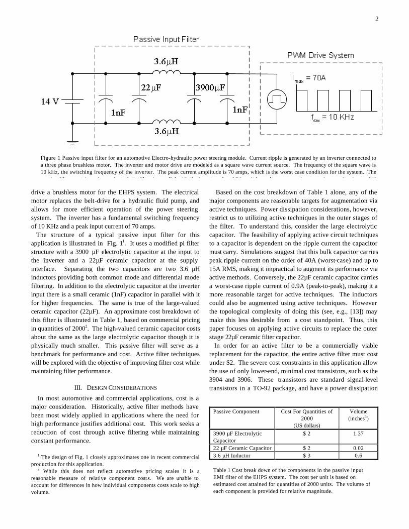
drive a brushless motor for the EHPS system. The electrical motor replaces the belt-drive for a hydraulic fluid pump, and allows for more efficient operation of the power steering system. The inverter has a fundamental switching frequency of 10 KHz and a peak input current of 70 amps.
The structure of a typical passive input filter for this application is illustrated in Fig. 11. It uses a modified pi filter structure with a 3900 µF electrolytic capacitor at the input to the inverter and a 22µF ceramic capacitor at the supply interface. Separating the two capacitors are two 3.6 µH inductors providing both common mode and differential mode filtering. In addition to the electrolytic capacitor at the inverter input there is a small ceramic (1nF) capacitor in parallel with it for higher frequencies. The same is true of the large-valued ceramic capacitor (22µF). An approximate cost breakdown of this filter is illustrated in Table 1, based on commercial pricing in quantities of 20002. The high-valued ceramic capacitor costs about the same as the large electrolytic capacitor though it is physically much smaller. This passive filter will serve as a benchmark for performance and cost. Active filter techniques will be explored with the objective of improving filter cost while maintaining filter performance.
III. DESIGN CONSIDERATIONS
In most automotive and commercial applications, cost is a major consideration. Historically, active filter methods have been most widely applied in applications where the need for high performance justifies additional cost. This work seeks a reduction of cost through active filtering while maintaining constant performance.
1 The design of Fig. 1 closely approximates one in recent commercial production for this application.
2 While this does not reflect automotive pricing scales it is a reasonable measure of relative component cost s. We are unable to account for differences in how individual components costs scale to high volume.
Based on the cost breakdown of Table 1 alone, any of the major components are reasonable targets for augmentation via active techniques. Power dissipation considerations, however, restrict us to utilizing active techniques in the outer stages of the filter. To understand this, consider the large electrolytic capacitor. The feasibility of applying active circuit techniques to a capacitor is dependent on the ripple current the capacitor must carry. Simulations suggest that this bulk capacitor carries peak ripple current on the order of 40A (worst-case) and up to 15A RMS, making it impractical to augment its performance via active methods. Conversely, the 22µF ceramic capacitor carries a worst-case ripple current of 0.9A (peak-to-peak), making it a more reasonable target for active techniques. The inductors could also be augmented using active techniques. However the topological complexity of doing this (see, e.g., [13]) may make this less desirable from a cost standpoint. Thus, this paper focuses on applying active circuits to replace the outer stage 22µF ceramic filter capacitor.
In order for an active filter to be a commercially viable replacement for the capacitor, the entire active filter must cost under $2. The severe cost constraints in this application allow the use of only lower-end, minimal cost transistors, such as the 3904 and 3906. These transistors are standard signal-level transistors in a TO-92 package, and have a power dissipation
Figure 1 Passive input filter for an automotive Electro-hydraulic power steering module. Current ripple is generated by an inverter connected to a three phase brushless motor. The inverter and motor drive are modeled as a square wave current source. The frequency of the square wave is 10 kHz, the switching frequency of the inverter. The peak current amplitude is 70 amps, which is the worst case condition for the system. The passive filter contains a large electrolytic filter in parallel with the inverter. In addition, it has a large, expensive ceramic capacitor in parallel
Passive Component Cost For Quantities of 2000
(US dollars)
Volume (inches3)
3900 µF Electrolytic Capacitor
$ 2 1.37
22 µF Ceramic Capacitor $ 2 0.02 3.6 µH Inductor $ 3 0.6 Table 1 Cost break down of the components in the passive input EMI filter of the EHPS system. The cost per unit is based on estimated cost attained for quantities of 2000 units. The volume of each component is provided for relative magnitude.
3
limit of around a third of a watt. Designing an amplifier to handle the full peak current ripple (0.9A peak) is difficult with such devices, and rapidly becomes cost prohibitive.
The outer-stage filter capacitor sees substantial ripple current in this application. This is characteristic of PWM drive filters. In dc/dc converter applications, the fundamental switching frequency is typically in or near the frequency range covered by EMI specifications (e.g., >150 kHz), and hence is greatly attenuated by the inner filter stages. PWM motor drives, however, typically switch at very low frequencies (10 kHz in the example considered here), which are well below the frequency range covered by EMI specifications. Therefore, a significant amount of the fundamental ripple appears at the filter output. That is, it is not cost effective (or required) to filter the fundamental switching frequency and its low-order harmonics, so these components are not greatly attenuated by the inner filter elements and still appear at the outer part of the filter. This is an important factor in design of active filter circuits for this application.
The large, low-frequency component in the ripple poses a substantial challenge in the active filter design because of the
increased power dissipation required to attenuate this ripple, which directly translates to an increase in cost. A saving factor lies in typical EMI specifications such as SAE J1113/41. While the majority of the ripple is due to the fundamental switching frequency of the inverter and its low-order harmonics, EMI ripple attenuation is only required from 150 kHz onward. If the active components are able to reject the low-frequency components (< 150 kHz) and operate only on the EMI frequencies, the power-driving requirement on the active filter is greatly reduced. Therefore, with appropriate design an active filter approach is viable in this application.
A further constraint is that the active filter circuitry must be powered from the available 14V power supply bus. Other power supply requirements would unacceptably increase the system cost. Given these constraints, design of the active filters for this application is quite interesting and challenging.
IV. ACTIVE TECHNIQUES FOR INPUT FILTERS
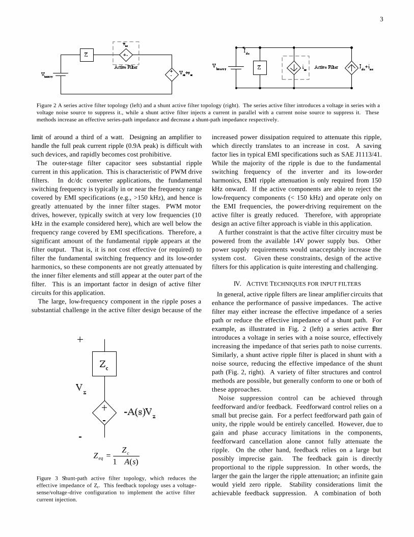
In general, active ripple filters are linear amplifier circuits that enhance the performance of passive impedances. The active filter may either increase the effective impedance of a series path or reduce the effective impedance of a shunt path. For example, as illustrated in Fig. 2 (left) a series active filter introduces a voltage in series with a noise source, effectively increasing the impedance of that series path to noise currents. Similarly, a shunt active ripple filter is placed in shunt with a noise source, reducing the effective impedance of the shunt path (Fig. 2, right). A variety of filter structures and control methods are possible, but generally conform to one or both of these approaches.
Noise suppression control can be achieved through feedforward and/or feedback. Feedforward control relies on a small but precise gain. For a perfect feedforward path gain of unity, the ripple would be entirely cancelled. However, due to gain and phase accuracy limitations in the components, feedforward cancellation alone cannot fully attenuate the ripple. On the other hand, feedback relies on a large but possibly imprecise gain. The feedback gain is directly proportional to the ripple suppression. In other words, the larger the gain the larger the ripple attenuation; an infinite gain would yield zero ripple. Stability considerations limit the achievable feedback suppression. A combination of both
)(1 sAZ
Z ceq +
=
Figure 3 Shunt-path active filter topology, which reduces the effect ive impedance of Zc. This feedback topology uses a voltage-sense/voltage-drive configuration to implement the active filter current injection.
Figure 2 A series active filter topology (left) and a shunt active filter topology (right). The series active filter introduces a voltage in series with a voltage noise source to suppress it., while a shunt active filter injects a current in parallel with a current noise source to suppress it. These methods increase an effective series-path impedance and decrease a shunt-path impedance respectively.
4
feedback and feedforward control is also possible.
V. ACTIVE FILTER DESIGN
A. Active Filter Topology
As previously described, this paper introduces a shunt active filter circuit to replace the output (battery-side) capacitor in the motor drive filter. The active filter reduces the shunt-path impedance at the filter output by enhancing the performance of a small capacitor using a feedback control configuration. A feedback approach was selected because it was found to be less costly to implement a high gain feedback circuit than to implement an amplifier with a precise gain and low phase shift in a feedforward configuration. Capacitor enhancement can be implemented using various means including current-sense/current-drive, voltage-sense/voltage-drive, current-sense/voltage-drive, and current-sense/current-drive [11,12]. A voltage-sense/voltage drive configuration was selected for cost reasons. Although the amplifier design uses a voltage drive, the overall active filter can be thought of as using current injection. The amplifier
drives a voltage across a load capacitor, which converts it into an AC current. This strategy is illustrated in Fig. 3 and provides an effective shunt-path impedance Zeq as shown there. Voltage drive enables low-loss injection to be achieved without an additional supply voltage, and voltage sensing is more economically realized than is current sensing for a given circuit gain. Although the active filter is implemented as one multistage amplifier, it is advantageous to break the design into two pieces: the sensing filter and the amplifier (see Fig. 4). The sensing filter, H(s), measures the voltage, and filters it to select which frequencies to pass onto the amplifier and which frequencies to reject. The amplifier, A, merely takes the voltage signal given by the sensing filter, amplifies it, and drives the resulting voltage across the reduced passive capacitor.
B. Design of Sensing Filter
The design of the sensing filter proves to be a primary challenge of this system. It determines the power dissipation of the drive stage and sets the closed-loop dynamics. The ideal sensing filter would have a sharp cutoff, essentially going
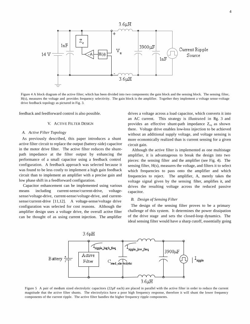
Figure 4 A block diagram of the active filter; which has been divided into two components: the gain block and the sensing block. The sensing filter, H(s), measures the voltage and provides frequency selectivity. The gain block is the amplifier. Together they implement a voltage sense-voltage drive feedback topology as pictured in Fig. 3.
Figure 5 A pair of medium sized electrolytic capacitors (22µF each) are placed in parallel with the active filter in order to reduce the current magnitude that the active filter shunts. The electrolytics have a poor high frequency response, therefore it will shunt the lower frequency components of the current ripple. The active filter handles the higher frequency ripple components.
5
from high attenuation to high gain in less than a decade, rejecting the fundamental (10 kHz) and low-order harmonics, and passing EMI frequencies (>150 kHz). Such a sharp cutoff would require a high order sensing filter, complicating the topology and making it more difficult to attain a stable feedback loop. Loop compensation may be added within the sensing filter to achieve stability, but this again adds complexity and oscillations may occur due to amplifier non-linearities3. Ultimately, amplifier nonidealities make it difficult to use a sensing filter with an order higher than one. Unfortunately, a first-order (high-pass) sensing filter does not provide enough separation between the pass band and stop band. The filter is unable to sufficiently attenuate the 10 KHz signal (to within the power limitations of the amplifier transistors), while still providing adequate gain at 150 KHz and beyond. To overcome these limitations, a low-frequency, low impedance bypass network is placed in parallel with the sensing filter, reducing the low frequency ripple voltage it
3 Nonlinearities can cause the loop gain of the feedback system to
decrease for certain input magnitudes, driving the system unstable.
sees. The network comprises one or more medium-sized electrolytic capacitors. The low cost of electrolytics makes this a viable solution. Electrolytic capacitors have poor performance at higher frequencies, where their ESL and ESR limit their ability to shunt current. By placing an electrolytic capacitor larger than 22 µF in parallel with the active filter, the lower frequency currents, including the 10 KHz fundamental, will be shunted from the active filter (see Fig 5); two 22 µF electrolytic capacitors are used in the prototype system. At higher EMI frequencies, where the electrolytic capacitor ceases to perform well, the active filter takes over and shunts the high-frequency currents. At still higher frequencies, beyond the bandwidth of the active circuit, a small ceramic capacitor serves as the shunt element.
C. Design of the Amplifier
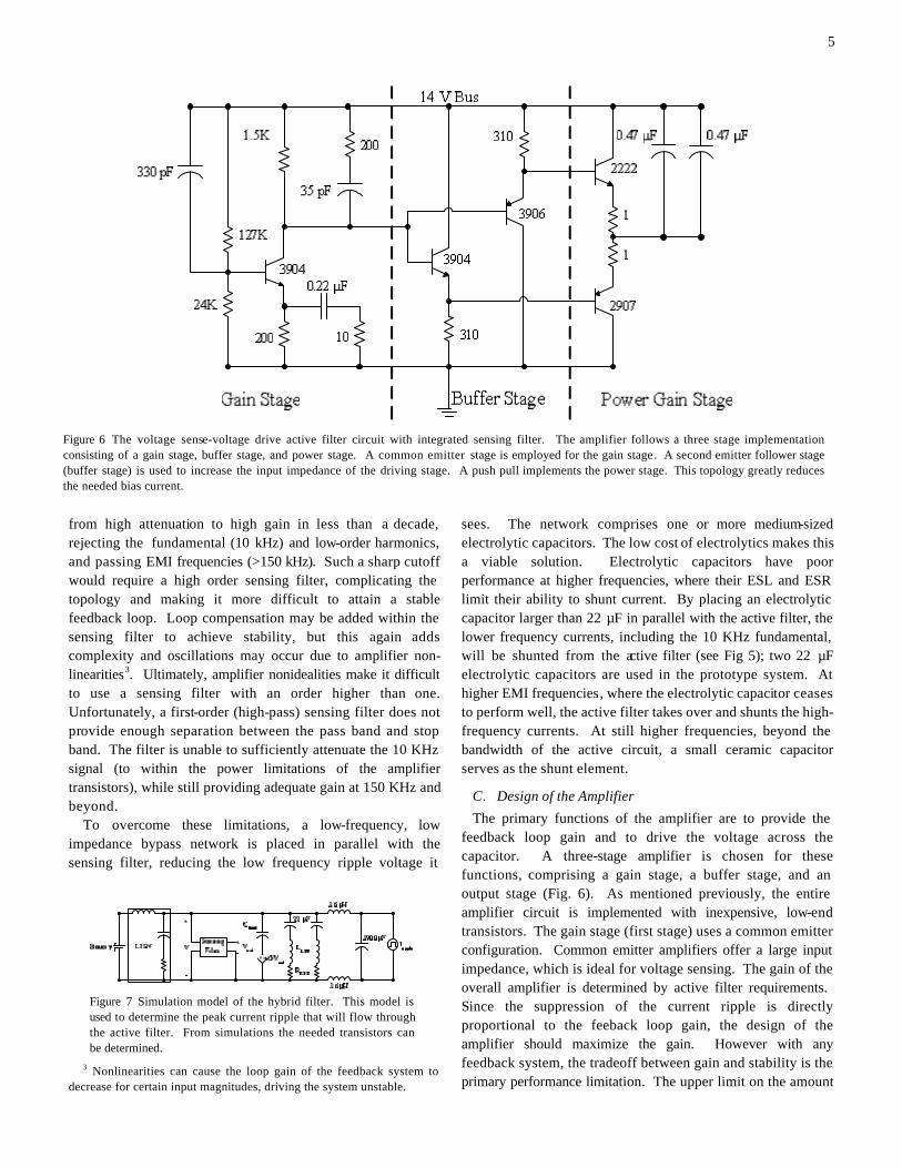
The primary functions of the amplifier are to provide the feedback loop gain and to drive the voltage across the capacitor. A three-stage amplifier is chosen for these functions, comprising a gain stage, a buffer stage, and an output stage (Fig. 6). As mentioned previously, the entire amplifier circuit is implemented with inexpensive, low-end transistors. The gain stage (first stage) uses a common emitter configuration. Common emitter amplifiers offer a large input impedance, which is ideal for voltage sensing. The gain of the overall amplifier is determined by active filter requirements. Since the suppression of the current ripple is directly proportional to the feeback loop gain, the design of the amplifier should maximize the gain. However with any feedback system, the tradeoff between gain and stability is the primary performance limitation. The upper limit on the amount
Figure 6 The voltage sense-voltage drive active filter circuit with integrated sensing filter. The amplifier follows a three stage implementation consisting of a gain stage, buffer stage, and power stage. A common emitter stage is employed for the gain stage. A second emitter follower stage (buffer stage) is used to increase the input impedance of the driving stage. A push pull implements the power stage. This topology greatly reduces the needed bias current.
Figure 7 Simulation model of the hybrid filter. This model is used to determine the peak current ripple that will flow through the active filter. From simulations the needed transistors can be determined.
6
of gain achievable is set by the stability of the system. As mentioned previously, the stability is highly dependent upon the sensing filter. The maximum amount of stable gain can be easily determined by standard feedback loop design techniques (a gain of 150 is used in the prototype). Furthermore, this amplifier configuration is bandwidth limited due to the Miller effect, which multiplies capacitances by the gain of the system. Fortunately, the bandwidth of the circuit (~2MHz) is sufficient for the application. The following two stages, the buffer stage and the output stage, are closely related. The buffer stage is implemented with two emitter followers and the output stage uses a push-pull configuration. The second stage provides large input impedance for the gain stage and biases the output stage. The gain stage has a relatively large output impedance therefore a buffer stage is needed to maintain the gain of the amplifier. The output stage has been designed to minimize DC bias currents and therefore the overall dissipation of the system. A push-pull circuit has no bias current, but it does have a dead zone. In the dead zone the output voltage is zero if the input voltage is within the thermal voltage of the transistor. A small
bias current is passed through both push-pull transistors in order to eliminate the dead zone (class AB). The two transistors are biased with emitter followers, which have the extra benefit of increasing the input impedance to the drive stage. One concern of a push-pull output stage is maintaining bias stability. In this configuration, it is possible for the current to increase with out bound. Placing resistors in the emitters of the push-pull transistors is one solution. The emitter resistors serve provide bias feedback and to limit the amount of current flow. The output stage does not provide any voltage gain. It serves as a voltage buffer and a power gain stage.
The voltage-sense/voltage-drive topology, which injects current, has the drawback of increased peak current, which affects the achievable bandwidth of the system. Simulation can facilitate the prediction of the peak current needed. The hybrid system is modeled as a sensing filter with lead compensation, two 22 µF electrolytic capacitors, and an ideal voltage gain driving a load capacitor (see Fig 7). Simulations show that the peak current needed is 500mA. The 3904 and 3906 transistors are not designed to handle these peak
Active Vs. Passive Ceramic
0
10
20
30
40
50
60
0.15 0.35 0.55 0.75 0.95 1.15 1.35 1.55 1.75 1.95Frequency (MHz)
Rip
ple
Acr
oss
50 O
hm L
ISN
(d
BV
)
ActiveCeramicSAE J1113/41 Class1 - 20dB
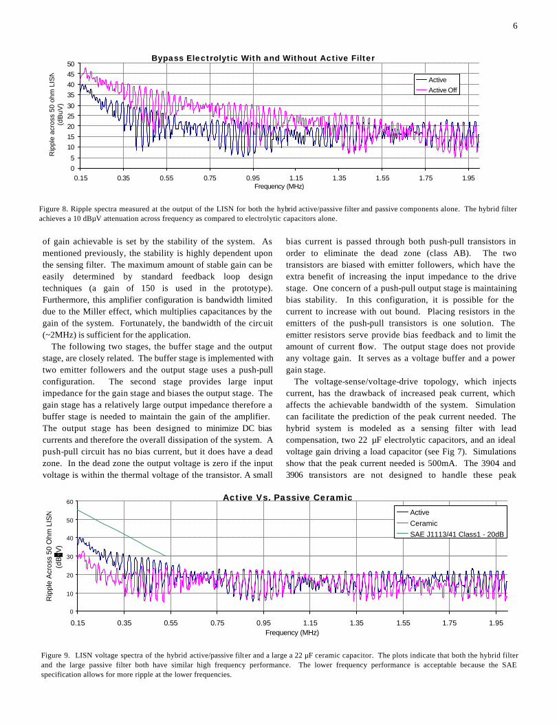
Figure 9. LISN voltage spectra of the hybrid active/passive filter and a large a 22 µF ceramic capacitor. The plots indicate that both the hybrid filter and the large passive filter both have similar high frequency performance. The lower frequency performance is acceptable because the SAE specification allows for more ripple at the lower frequencies.
Bypass Electrolytic With and Without Active Filter
05
1015202530
35404550
0.15 0.35 0.55 0.75 0.95 1.15 1.35 1.55 1.75 1.95Frequency (MHz)
Rip
ple
acro
ss 5
0 oh
m L
ISN
(d
BuV
)
ActiveActive Off
Figure 8. Ripple spectra measured at the output of the LISN for both the hybrid active/passive filter and passive components alone. The hybrid filter achieves a 10 dBµV attenuation across frequency as compared to electrolytic capacitors alone.
7
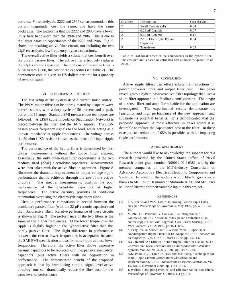
currents. Fortunately, the 2222 and 2906 can accommodate this current magnitude, cost the same, and have the same packaging. The tradeoff is that the 2222 and 2906 have a lower unity beta bandwidth than the 3904 and 3906. This is due to the larger parasitic capacitances of the 2222 and 2906. Fig. 6 shows the resulting active filter circuit, not including the two 22µF electrolytic, low-frequency, bypass capacitors. The overall active filter yields a substantial cost benefit over the purely passive filter. The active filter effectively replaces the 22µF ceramic capacitor. The total cost of the active filter is $0.70 verses $2.00, the cost of the capacitor (see Table 2). The component cost is given as US dollars per unit for a quantity of two thousand.
VI. EXPERIMENTAL RESULTS
The test setup of the system used a current noise source. The PWM motor drive can be approximated by a square wave current source, with a duty cycle of 50 percent and a peak current of 15 amps. Standard EMI measurement techniques are followed. A LISN (Line Impedance Stabilization Network) is placed between the filter and the 14 V supply. The LISN passes power frequency signals to the load, while acting as a known impedance at ripple frequencies. The voltage across the 50 ohm LISN resistor is used as the metric for input ripple performance.
The performance of the hybrid filter is determined by first taking measurements without the active filter element. Essentially, the only outer-stage filter capacitance is the two medium sized (22µF) electrolytic capacitors. Measurements were then taken with the active filter in operation. Figure 8 illustrates the dramatic improvement in output voltage ripple performance that is achieved through the use of the active circuitry. The spectral measurements confirm the poor performance of the electrolytic capacitors at higher frequencies. The active circuitry provides an additional attenuation over using the electrolytic capacitors alone.
Next, a performance comparison is needed between the benchmark passive filter (with the 22 µF ceramic capacitor) and the hybrid/active filter. Relative performance of these circuits is shown in Fig. 9. The performance of the two filters is the same at the higher frequencies. At the lower frequencies the ripple is slightly higher in the hybrid/active filter than the purely passive filter. The slight difference in performance between the two at lower frequencies is acceptable because the SAE EMI specification allows for more ripple at these lower frequencies. Therefore, the active filter allows expensive ceramic capacitors to be replaced with inexpensive electrolytic capacitors (plus active filter) with no degradation in performance. The demonstrated benefit of the proposed approach is that by introducing simple, signal-level active circuitry, one can dramatically reduce the filter cost for the same level of performance
VII. CONCLUSION
Active ripple filters can effect substantial reductions in power converter input and output filter cost. This paper investigates a hybrid passive/active filter topology that uses a shunt filter approach in a feedback configuration. The design of a sense filter and amplifier suitable for the application are investigated. The experimental results demonstrate the feasibility and high performance of the new approach, and illustrate its potential benefits. It is demonstrated that the proposed approach is most effective in cases where it is desirable to reduce the capacitance cost in the filter. In these cases, a cost reduction of 65% is possible, without impacting ripple performance.
ACKNOWLEDGMENT
The authors would like to acknowledge the support for this research provided by the United States Office of Naval Research under grant number N00014-00-1-0381, and by the member companies of the MIT/Industry Consortium on Advanced Automotive Electrical/Electronic Components and Systems. In addition the authors would like to give special thanks to Mr. Philip Desmond of Motorola AIEG and Mr. Peter Miller of Ricardo for their valuable input in this project.
REFERENCES [1] T.K. Phelps and W.S. Tate, “Optimizing Passive Input Filter
Design,” Proceedings of Powercon 6, May 1979, pp. G1-1 - G1-10.
[2] M. Zhu, D.J. Perreault, V. Caliskan, T.C. Neugebauer, S. Guttowski, and J.G. Kassakian, “Design and Evaluation of an Active Ripple Filter with Rogowski-Coil Current Sensing,” IEEE PESC Record , Vol. 2, 1999, pp. 874 -880.
[3] S. Feng , W. A. Sander, and T. Wilson, “Small-Capacitance Nondissipative Ripple Filters for DC Supplies,” IEEE Transactions on Magnetics, Vol. 6, No. 1, March 1970, pp. 137-142.
[4] D.C. Hamill “An Efficient Active Ripple Filter for Use in DC-DC Conversion,” IEEE Transactions on Aerospace and Electronic Systems, Vol. 32, No. 3, July 1996, pp. 1077-1084.
[5] N.K. Poon, J.C.P. Liu, C.K. Tse, and M.H Pong, “Techniques for Input Ripple Current Cancellation: Classification and Implementation,” IEEE Transactions on Power Electronics, Vol. 15, No. 6, November 2000, pp. 1144-1152.
[6] J. Walker, “Designing Practical and Effective Active EMI filters,” Proceedings of Powercon 11, 1984, I-3 pp. 1-8.
Quantity Description Cost ($)/Unit 2 Small Ceramic (pF) 0.04 1 0.22 µF Ceramic 0.07 2 0.47 µF Ceramic 0.11 2 22 µF Electrolytic Bypass
Capacitor 0.04
5 Transistors 0.05 Table 2: Cost break down of the components in the hybrid filter. The cost per unit is based on estimated cost attained for quantities of 2000.
8
[7] L.E. LaWhite and M.F. Schlecht, “Active Filters for 1 MHz Power Circuits With Strict Input/Output Ripple Requirements,” IEEE Transactions on Power Electronics, Vol. PE-2, No.4, October 1987, pp. 282-290.
[8] T. Farkas and M.F. Schlecht, “Viability of Active EMI Filters for Utility Applications,” IEEE Transactions on Power Electronics, Vol. 9, No. 3, May 1994, pp. 328-337.
[9] M.S. Moon and B.H. Cho, “Novel Active Ripple Filter for the Solar Array Shunt Switching Unit ,” Journal of Propulsion and Power, Vol. 12, No. 1, January-February 1996, pp. 78-82.
[10] P. Midya and P.T. Krein, “Feed-forward Active Filter for Output Ripple Cancellation,” International Journal Electronics, Vol. 77, No. 5, pp. 805-818.
[11] L.R. Casey, A. Goldberg, and M.F. Schlecht, “Issues Regarding the Capacitance of 1-10 MHz Transformers,” Proceedings IEEE APEC, 1988, pp. 352 –359.
[12] A. Goldberg, J.G. Kassakian, and M.F. Schlecht, “Issues Related to 1-10-MHZ Transformer Design,” IEEE Transactions on Power Electronics, Vol. 4, No. 1, January 1989, pp. 113-123.
[13] A.C. Chow, D.J. Perreault, “Design and evaluation of an active ripple filter using voltage injection,” IEEE PESC Record, Vol.1, 2001, pp. 390 –397.