Embed Size (px)
Citation preview

ENGLISH
CP9575
Actron AutoScanner®
OBD II Scan Tool
2
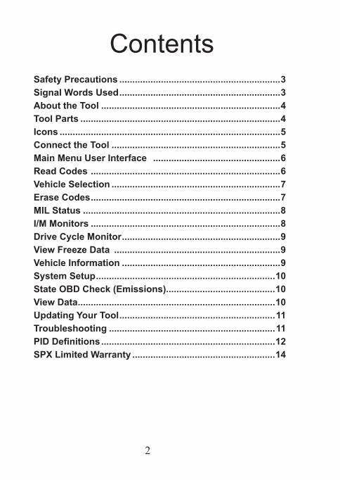
ContentsSafety Precautions ..............................................................3Signal Words Used ..............................................................3About the Tool .....................................................................4Tool Parts .............................................................................4Icons .....................................................................................5Connect the Tool .................................................................5Main Menu User Interface .................................................6Read Codes .........................................................................6Vehicle Selection .................................................................7Erase Codes .........................................................................7MIL Status ............................................................................8I/M Monitors .........................................................................8Drive Cycle Monitor .............................................................9View Freeze Data ................................................................9Vehicle Information .............................................................9System Setup .....................................................................10State OBD Check (Emissions)..........................................10View Data ............................................................................10Updating Your Tool ............................................................11Troubleshooting ................................................................11PID Definitions ...................................................................12SPX Limited Warranty .......................................................14
3
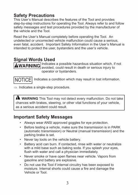
Safety PrecautionsThis User’s Manual describes the features of the Tool and provides step-by-step instructions for operating the Tool. Always refer to and follow safety messages and test procedures provided by the manufacturer of the vehicle and the Tool.
Read the User’s Manual completely before operating the Tool. An undetected or uncorrected vehicle malfunction could cause a serious, even fatal, accident. Important Safety Information in the User’s Manual is intended to protect the user, bystanders and the user’s vehicle.
Signal Words UsedIndicates a possible hazardous situation which, if not avoided, could result in death or serious injury to operator or bystanders.
Indicates a condition which may result in lost information.
⇒ Indicates a single-step procedure.
Important Safety Messages• Always wear ANSI approved goggles for eye protection.• Before testing a vehicle, make sure the transmission is in PARK
(automatic transmission) or Neutral (manual transmission) and the parking brake is set.
• Never lay tools on the vehicle battery.• Battery acid can burn. If contacted, rinse with water or neutralize
with a mild base such as baking soda. If you splash your eyes, flushwithwaterandcallaphysicianimmediately.
• Neversmokeorhaveopenflamesnearvehicle.Vaporsfromgasoline and battery are explosive.
• Do not use the Tool if internal circuitry has been exposed to moisture.InternalshortscouldcauseafireanddamagetheVehicleorTool.
NOTICE
WARNING This Tool may not detect every malfunction. Do not take chances with brakes, steering, or other vital functions of your vehicle, as a serious accident could result.
4
• Always turn the ignition key OFF when connecting or disconnecting electrical components, unless otherwise instructed.
• Most vehicles are equipped with air bags. If you elect to work around air bag components or wiring, follow your vehicle service manual cautions. You could be seriously injured or killed by an unintended deployment.
The air bag can still open several minutes after ignition is turned off.
• Always follow vehicle manufacturer’s warnings, cautions, and service procedures.
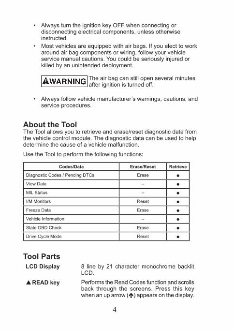
About the ToolThe Tool allows you to retrieve and erase/reset diagnostic data from the vehicle control module. The diagnostic data can be used to help determine the cause of a vehicle malfunction.
Use the Tool to perform the following functions:
Codes/Data Erase/Reset Retrieve
Diagnostic Codes / Pending DTCs Erase
ViewData --
MIL Status --
I/M Monitors Reset
Freeze Data Erase
VehicleInformation --
State OBD Check Erase
Drive Cycle Mode Reset
Tool PartsLCD Display 8 line by 21 character monochrome backlit
LCD. READ key Performs the Read Codes function and scrolls
back through the screens. Press this key when an up arrow () appears on the display.
5
ERASE key Performs the Erase Codes function and scrolls forward through the screens. Press this key when a down arrow () appears on the display.
ENTER key Selects displayed items. BACK key Returns to the Main Menu or previous screen.OBD II Connector Connects the Tool to the vehicle connector.
IconsThe following icons may appear on the display:
Indicates additional information is available on next screen by using the ERASE key.
Indicates additional information is available on pre-vious screen by using the READ key.
IndicatesaPendingDTC.ForadefinitionofPend-ing DTC see page 6.
# of # Appears only when viewing codes. Indicates code sequence and quantity (code # of n). For example, if you see 2 of 9 you are looking at the 2nd of 9 codes reported by the computer module.
Mod $## Appears only when viewing codes. Indicates the computer module that reported the code.Indicates that the READ and ERASE hot keys are active.
Connect the ToolTo connect the Tool to the vehicle:
1. Locate the OBD II connector under the steering column. If the connector is not there, a label should be there indicating the whereabouts of the connector. For more information on OBD II connectors, go to http://www.obdclearinghouse.com/oemdb.
2. If necessary, remove the cover from the vehicle connector.
3. Turn the ignition switch to the ON position. Do not start the engine.
6
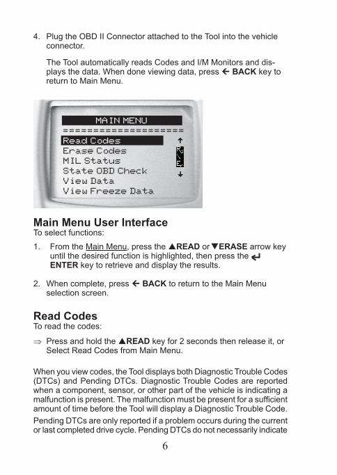
4. Plug the OBD II Connector attached to the Tool into the vehicle connector. The Tool automatically reads Codes and I/M Monitors and dis-plays the data. When done viewing data, press BACK key to return to Main Menu.
MAIN MENU
====================
Read Codes
Erase Codes
MIL Status
State OBD Check
View Data
View Freeze Data
^^
Main Menu User Interface To select functions:
1. From the Main Menu, press the READ or ERASE arrow key until the desired function is highlighted, then press the ENTER key to retrieve and display the results.
2. When complete, press BACK to return to the Main Menu selection screen.
Read Codes To read the codes:
⇒ Press and hold the READ key for 2 seconds then release it, or Select Read Codes from Main Menu.
When you view codes, the Tool displays both Diagnostic Trouble Codes (DTCs) and Pending DTCs. Diagnostic Trouble Codes are reported when a component, sensor, or other part of the vehicle is indicating a malfunctionispresent.Themalfunctionmustbepresentforasufficientamount of time before the Tool will display a Diagnostic Trouble Code.Pending DTCs are only reported if a problem occurs during the current or last completed drive cycle. Pending DTCs do not necessarily indicate
7
a faulty component or system. Pending DTCs convert to Diagnostic Trouble Codes when an emissions problem persists long enough to be considered a real problem, not an anomaly. Pending DTCs are indicated by a icon.
Vehicle SelectionVehicleSelectionwillbedisplayedforReadCodeswhenamanufacturerspecificDTCisretrievedfromthevehicle.
Erase CodesThe Erase function performs the following:
9 Erases Codes (both Diagnostic Trouble Codes and Pending DTCs)
9 May erase Freeze Data results depending on the vehcle.
9 Sets I/M Monitors to not ready.
NOTICE Perform Erase Codes function only after systems have been checked completely and DTCs have been written down.
To erase codes from the vehicle computer: 1. Set the ignition to Key On and Engine Off. Do NOT start the
vehicle. The engine should not be running.
2. Press and hold the ERASE key for 3 seconds then release, or Select Erase Codes from Main Menu and press ENTER.
3. Whentheconfirmationmessageappearsonthedisplay,chooseone of the following options.• To proceed with the operation: Press ENTER for YES.• To cancel the operation and return to the Main Menu: Press BACK for NO.
The Tool will automatically perform the Read Codes function after erasing codes. The Tool will then indicate the number of codes remaining.
NOTICE If after erasing codes a DTC returns, the problem has notbeenfixedorotherfaultsarepresent.
8
MIL StatusMIL (Malfunction Indicator Lamp) status indicates if the vehicle com-puter is telling the MIL to illuminate when the engine is running.
• MIL ON indicates that the check Engine Light should be ON. • MIL OFF indicates that the Malfunction Indicator Lamp
should be OFF.
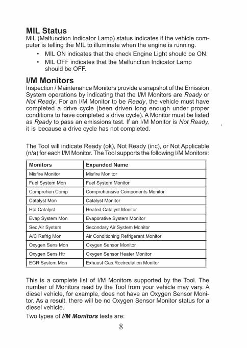
I/M MonitorsInspection / Maintenance Monitors provide a snapshot of the Emission System operations by indicating that the I/M Monitors are Ready or Not Ready. For an I/M Monitor to be Ready, the vehicle must have completed a drive cycle (been driven long enough under proper conditions to have completed a drive cycle). A Monitor must be listed as Ready to pass an emissions test. If an I/M Monitor is Not Ready, it is because a drive cycle has not completed.
The Tool will indicate Ready (ok), Not Ready (inc), or Not Applicable (n/a) for each I/M Monitor. The Tool supports the following I/M Monitors:
Monitors Expanded NameMisfireMonitor MisfireMonitor
Fuel System Mon Fuel System Monitor
Comprehen Comp Comprehensive Components Monitor
Catalyst Mon Catalyst Monitor
Htd Catalyst Heated Catalyst Monitor
Evap System Mon Evaporative System Monitor
Sec Air System Secondary Air System Monitor
A/C Refrig Mon Air Conditioning Refrigerant Monitor
Oxygen Sens Mon Oxygen Sensor Monitor
Oxygen Sens Htr Oxygen Sensor Heater Monitor
EGR System Mon Exhaust Gas Recirculation Monitor
This is a complete list of I/M Monitors supported by the Tool. The number of Monitors read by the Tool from your vehicle may vary. A diesel vehicle, for example, does not have an Oxygen Sensor Moni-tor. As a result, there will be no Oxygen Sensor Monitor status for a diesel vehicle. Two types of I/M Monitors tests are:
9
� Since DTCs Cleared - shows status of the monitors since the DTCs were last erased.
� This Drive Cycle - shows status of monitors since the start of the current drive cycle. Refer to the vehicle service manual for more detailed information on emission-related monitors and their status.
9 Some vehicles do not support This Drive Cycle. If vehicle supports both types of monitors the I/M Monitors Menu displays.
Drive Cycle MonitorThe Drive Cycle Monitor function is very similar to the I/M Monitors though the Drive Cycle Monitor is used to view REAL TIME operations of the Emissions System on OBD II vehicles.
9 Drive Cycle Monitor continuously updates as the vehicle reports operations of the Emission System.
9 Refer to the vehicle service manual for how to perform a drive cycleonyourspecificvehicle.
9 Drive Cycle Monitor will only show the monitors that are inc (incomplete). When all monitors are complete the Tool will display a message.
See I/M Monitors for more information.
View Freeze Data Displays a snapshot of operating conditions at the time the Diagnostic TroubleCodewascreated.SeePIDDefinitionsformoreinformation.
Vehicle InformationTheVehicleInformationfunctionallowstheTooltorequestthevehicle’sVINnumber,calibrationID(s)whichidentifiessoftwareversioninvehiclecontrolmodule(s),calibrationverificationnumbers(CVN(s)),andIn-usePerformance Tracking (IPT). Vehicle Information functionapplies tomodelyear2000andnewerOBD II compliant vehicles.
NOTICE TheVehicleInformationfunctionisnotsupportedbyallvehicles. Also, not every vehicle supports every piece of information(forexample,CVN,IPT,VIN).
10
System SetupSystem Setup allows:
• Display contrast to be changed,• Tool information to be viewed,• Display to be checked,• Operation of the keypad to be checked,• Memory of the Tool to be checked, • Language to be changed, • Units of measure to be changed.
State OBD Check (Emissions)The State OBD Check function is used to display a basic status of the vehicle’s OBD system.
The State OBD Check function has the following areas:
� MIL STATUS ON or OFF � Number of Codes Found � Number of Monitors OK � Number of Monitors Inc � Number of Monitors N/A
9 State OBD Check should be done with the key on engine running (KOER) due to showing MIL status.
9 The number of codes found are only DTCs and not Pending DTCs.
9 The number of Monitors that are either OK, INC or NA are only Since DTCs Cleared and not This Drive Cycle.
9 Refer to Read Codes and I/M Monitors for more detailed information about the results.
View Data TheViewData function allows real time viewing of the vehicle’scomputer module’s PID data. As the computer monitors the vehicle, information is simultaneously transmitted to the Tool.
11
ViewDataallowsthefollowingitemstobeviewedontheTool:
� Sensor data � Operation of switches � Operation of solenoids � Operation of relays
Multiple PIDs may be sent if vehicle is equipped with more than one computer module (for example a powertrain control module [PCM] andatransmissioncontrolmodule[TCM].TheToolidentifiesthembytheiridentificationnames(ID)assignedbymanufacturer(i.e.$10or$1A).SeePIDDefinitionsformoreinformation.
Updating Your Tool
1. Download Scanning Suite from http://www.Actron.com/downloads/.2. Install Scanning Suite.3. Connect USB Cable to Tool and PC.4. Start Scanning Suite. Click on Tool Update Icon and follow in-
structions.
Troubleshooting � If a “LINK ERROR” message appears, cycle the ignition key totheOFFpositionfor10seconds,thenbackON,thenpressthe ENTER key. Make sure the ignition key is in the ON no t the ACCESSORY position.
� If the MIL Status is ON and the MIL is not illuminated with the engine running, then a problem exists in the MIL circuit.
12
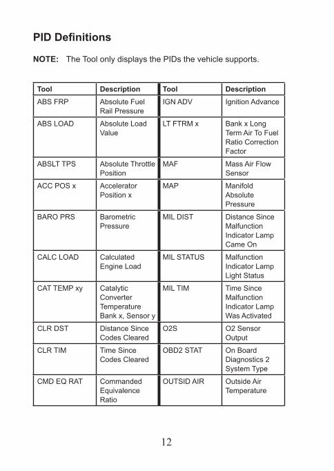
PID Definitions
NOTE: The Tool only displays the PIDs the vehicle supports.
Tool Description Tool DescriptionABS FRP Absolute Fuel
Rail PressureIGNADV Ignition Advance
ABS LOAD Absolute Load Value
LT FTRM x Bank x Long Term Air To Fuel Ratio Correction Factor
ABSLT TPS Absolute Throttle Position
MAF Mass Air Flow Sensor
ACC POS x Accelerator Position x
MAP Manifold Absolute Pressure
BARO PRS Barometric Pressure
MIL DIST Distance Since Malfunction Indicator Lamp Came On
CALC LOAD Calculated Engine Load
MIL STATUS Malfunction Indicator Lamp Light Status
CAT TEMP xy Catalytic Converter Temperature Bank x, Sensor y
MIL TIM Time Since Malfunction Indicator Lamp Was Activated
CLR DST Distance Since Codes Cleared
O2S O2 Sensor Output
CLR TIM Time Since Codes Cleared
OBD2 STAT On Board Diagnostics 2 System Type
CMD EQ RAT Commanded Equivalence Ratio
OUTSID AIR Outside Air Temperature
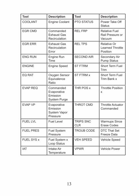
13
Tool Description Tool DescriptionCOOLANT Engine Coolant PTO STATUS Power Take Off
Status
EGR CMD Commanded Exhaust Gas Recirculation
REL FRP Relative Fuel Rail Pressure or Vacuum
EGR ERR Exhaust Gas Recirculation Error
REL TPS Relative Or Learned Throttle Position
ENG RUN Engine Run Time
SECOND AIR Secondary Air Pump Status
ENGINE Engine Speed ST FTRM Short Term Fuel Trim
EQ RAT Oxygen Sensor Equivalence Ratio
ST FTRM x Short Term Fuel Trim Bank x
EVAPREQ Commanded Evaporative Emission System Purge
THR POS x Throttle Position x
EVAPVP Evaporative Emission SystemVaporPressure
THROT CMD Throttle Actuator Commanded
FUELLVL Fuel Level TRIPS SNC CLR
Warmups Since Erase Codes
FUEL PRES Fuel System Pressure
TROUB CODE DTC That Set Freeze Data
FUEL SYS x Fuel System x Loop Status
VEHSPEED VehicleSpeed
IAT Intake Air Temperature
VPWR VehiclePower
14
SPX Limited WarrantyTHIS WARRANTY IS EXPRESSLY LIMITED TO ORIGINAL RETAIL BUYERS OF SPX ELECTRONIC DIAGNOSTIC TOOLS (“UNITS”).
SPX Units are warranted against defects in materials and workmanship for one year (12 months) from date of delivery. This warranty does not cover any Unit that has been abused, altered, used for a purpose other than that for which it was intended, or used in a manner inconsistent with instructions regarding use. The sole and exclusive remedy for any Unit found to be defective is repair or replacement, the option of SPX. In no event shall SPX be liable for any direct, indirect, special, incidental or consequential damages (including lost profit) whether based on warranty, contract, tort or any other legal theory. The existence of a defect shall be determined by SPX in accordance with procedures established by SPX. No one is authorized to make any statement or representation altering the terms of this warranty.
DISCLAIMERTHEABOVEWARRANTYISINLIEUOFANYOTHERWARRANTY,EXPRESS OR IMPLIED, INCLUDING ANY WARRANTY OF MERCHANTABILITY OR FITNESS FOR A PARTICULAR PURPOSE.
SOFTWAREUnitsoftwareisproprietary,confidentialinformationprotectedundercopyrightlaw.Usershave no right in or title to Unit software other than a limited right of use revocable by SPX. Unit software may not be transferred or disclosed without written consent of SPX. Unit software may not be copied except in ordinary backup procedures.
TO USE YOUR WARRANTYIf you need to return the unit, please follow this procedure:1.CallSPXCorporationTechnicalSupportat1-(800)228-7667.OurTechnicalService
Representatives are trained to assist you.2. Proof of purchase is required for all warranty claims. For this reason we ask that
you retain your sales receipt.3. In the event that product needs to be returned, the Technical Service Representative
will provide you with the address where you can send the unit.4. You will need to provide us with a contact name, daytime phone number, and a
description of the problem.5. If possible, return the product in its original package with cables and
accessories.6. Include your return address on the outside of the package and send the unit to the
address provided by your Technical Service Representative.7.Youwillberesponsibleforshippingchargesintheeventthatyourrepairisnot
covered by warranty.
OUT OF WARRANTY REPAIRIf you need product repaired after your warranty has expired, please call Technical Supportat(800)228-7667.

15

©2009SPX.AllRightsReserved.0002-000-3106