Embed Size (px)
Citation preview

INSTRUCTION MANUAL
1WMPD4000506B
AD-4406 OP-03/04/05/07/08/11
WEIGHING INDICATOR
INSTRUCTION MANUAL
This Manual and Warning Definitions The warnings described in this manual have the following meanings:
CAUTION Disregarding the caution could result in loss of important data or damage to the instrument
Note Provides information useful for the user to operate the instrument.
This is a hazard alert mark.
© 2009 A&D Company, Limited. All rights reserved. No part of this publication may be reproduced, transmitted, transcribed, or translated into any language in any form by any means without the written permission of A&D Company, Limited. The contents of this manual and the specifications of the instrument covered by this manual are subject to change for improvement without notice.
AD-4406 Weighing Indicator Page 1
Contents
1. Compliance ....................................................................................................................3 1.1. Compliance with FCC Rules ............................................................................................. 3 1.2. Compliance with European Directive ................................................................................ 3
2. Introduction....................................................................................................................4
3. Installation and Precautions .........................................................................................5 3.1. Installation and Precautions .............................................................................................. 5 3.2. Power Supply .................................................................................................................... 5 3.3. The Load Cell Connections ............................................................................................... 6 3.4. Adjustment of the Load Cell Output .................................................................................. 6 3.5. Verifying Load Cell Output and Input Sensitivity ............................................................... 7 3.6. Installing an Option Board ................................................................................................. 7 3.7. Attaching the Display Stand (OP-11) ................................................................................ 7
4. Description of Panels and Symbols.............................................................................8 4.1. Front Panel Description..................................................................................................... 8 4.2. Rear Panel Description ..................................................................................................... 9 4.3. Other Displays and Symbols ............................................................................................. 9 4.4. Accessories....................................................................................................................... 9
5. Calibration ....................................................................................................................10 5.1. Items of the Calibration Mode ......................................................................................... 10 5.2. Calibration Procedure...................................................................................................... 11
5.2.1. Configuring a Weighing Instrument ............................................................................. 11 5.2.2. Specifying the Range and Unit.................................................................................... 12 5.2.3. Specifying the Resolution, Decimal Point Position and Format .................................. 12 5.2.4. Specifying the Weighing Capacity of the First Range ................................................. 13 5.2.5. Specifying the Second Range Resolution ................................................................... 13 5.2.6. Specifying the Second Range Capacity ...................................................................... 13 5.2.7. To Get Stabilized Data ................................................................................................ 13 5.2.8. Zero Calibration........................................................................................................... 14 5.2.9. Span Calibration.......................................................................................................... 14 5.2.10. Exiting the Calibration Mode ....................................................................................... 15
5.3. Weighing Range Function ............................................................................................... 16 5.3.1. Setting the Division and Range ................................................................................... 17
5.4. Digital Linearization Function .......................................................................................... 17 5.5. Gravity Compensation Function......................................................................................... 18
5.5.1. The Gravity Acceleration Table ................................................................................... 19
5.6. Calibration Error Code List................................................................................................. 20
6. Functions......................................................................................................................21
Page 2 AD-4406 Weighing Indicator
6.1. Changing the Function Settings ......................................................................................... 21 6.2. F-Functions ..................................................................................................................... 22 6.3. CF-Functions.................................................................................................................... 29
7. Function keys F1 and F2 .............................................................................................30
8. Tare ...............................................................................................................................31
9. Accumulation ...............................................................................................................32 9.1. Preparation and Specification ......................................................................................... 32 9.2. Display and Operation..................................................................................................... 33
10. Code Memory .............................................................................................................35
11. Comparison................................................................................................................36 11.1. Weight Check Mode........................................................................................................ 36
11.1.1. Condition Formula for Comparison ............................................................................. 37 11.1.2. Setting the Upper/Lower Limit Values ......................................................................... 37
11.2. Setpoint Comparison....................................................................................................... 39 11.2.1. Description of Input Parameters and Outputs ............................................................. 39 11.2.2. Simple Batch ............................................................................................................... 40 11.2.3. Setting the Parameters of Setpoint Comparison ......................................................... 41
12. Hold Function.............................................................................................................42 12.1. Setting the Hold Functions .............................................................................................. 42
13. RS-232C Interface (OP-04, OP-05, OP-08)................................................................44 13.1. Specifications .................................................................................................................. 44 13.2. Data Format .................................................................................................................... 45 13.3. Command Format ........................................................................................................... 45
13.3.1. Commands to Request Data ....................................................................................... 46 13.3.2. Commands to Control the Indicator............................................................................. 47 13.3.3. Commands to Set Parameters .................................................................................... 49 13.3.4. Commands for Hold Function...................................................................................... 49 13.3.5. Commands to Set Serial Data Output Format (UFC).................................................. 50
13.4. UFC Command ............................................................................................................... 50
14. RS-422/RS-485, Relay Output (OP-03)......................................................................52
15. Relay Output & Control Input (OP-05)......................................................................54
16. 4-20 mA Analog Output (OP-07) ...............................................................................55
17. Current Loop Output (OP-08)....................................................................................56
18. Specifications ............................................................................................................58 18.1. Dimensions...................................................................................................................... 59
AD-4406 Weighing Indicator Page 3
1. Compliance
1.1. Compliance with FCC Rules Please note that this equipment generates, uses and can radiate radio frequency
energy. This equipment has been tested and has been found to comply with the limits of a Class A computing device pursuant to Subpart J of Part 15 of FCC rules. These rules are designed to provide reasonable protection against interference when this equipment is operated in a commercial environment. If this unit is operated in a residential area it may cause some interference and under these circumstances the user would be required to take, at his own expense, whatever measures are necessary to eliminate the interference.
(FCC = Federal Communications Commission in the U.S.A.)
1.2. Compliance with European Directive This appliance complies with the statutory EMC (Electromagnetic Compatibility)
directive 89/336/EEC and the Low Voltage Directive 73/23/EEC for safety of electrical equipment designed for certain voltages.
Note The displayed value may be adversely affected under extreme electromagnetic influences.
1. Compliance
Page 4 AD-4406 Weighing Indicator
2. Introduction
The AD-4406 is a compact weighing indicator that amplifies the signal from a load cell, converts it to digital data and displays it as a mass value.
This indicator has the following performance: Input sensitivity: ......................... 0.2 µV/division Maximum display: ...................... 40000 divisions Display update rate:................... 10 times/second approximately Input voltage range: ................... -1 mV to +15 mV
The following standard functions are available: The HiHi/Hi/OK/Lo/LoLo limit comparison to check a mass value. The setpoint comparison for batching applications. There are four code memories to store the above mentioned data. The accumulation function to totalize these mass values and to count the
number of accumulations. The hold function enables weighing a live animal. UFC (Universal Flexi Coms) function to customize the protocol of outputting data
using the serial interface. The following interfaces are either standard or are available as an option:
The RS-232C serial interface to communicate with a computer, printer or remote display. This interface outputs data and can request weight data, enter parameters and control the state of the indicator. (Options: OP-04, OP-05, OP-08)
RS-422/485, 3-Relay Outputs (Option: OP-03) RS-232C, 3-Relay Outputs and 3-Control Inputs (Option: OP-05) Analog Output (4-20 mA) (Option: OP-07) RS-232C, Current Loop Output, 3-Relay Outputs and 1-Control Input (Option:
OP-08) Only one interface can be installed at a time.
The calibration mode includes the following functions: Setting of the minimum division (weighing interval) and the maximum capacity Zero and span calibration The weighing range function of the multi-interval weighing instrument (scale) Digital linearization function Gravity compensation function
2. Introduction
AD-4406 Weighing Indicator Page 5
3. Installation and Precautions
3.1. Installation and Precautions The AD-4406 weighing indicator is a precision electronic instrument. Handle the
indicator carefully. The operating temperature is -10 to +40 (14 to 104 ). Do not install the indicator in direct sunlight. A malfunction or other problems may be caused by an unstable power source including
momentary power failure or instantaneous noise. Use a stable power source. When an AC Adapter is used, please confirm that the local voltage and receptacle type
are correct for your indicator. Use shielded cables for all connections. Connect the cable shields to the shield
terminal or case as an earth terminal. Earth ground the indicator. Do not join the earth ground line with other electrical
power equipment. Do not install the indicator in a place where it is apt to be charged with static
electricity, or where the relative humidity is less than 45%. Plastic and isolators are apt to be charged with static electricity.
3.2. Power Supply
When an AC adapter is used A stable power source must be used; an unstable power source which includes an instantaneous noise component may result in a malfunction.
When standard batteries are used Use six new size C batteries, preferably alkaline type. Remove the battery cover. Press in and up on the end of the battery box. Slowly release pressure on the battery box while holding it against the top of the battery compartment. The battery box will slide out. Insert the batteries into the battery box, taking care of the polarity of the batteries. Then, insert the battery box, contact end first, into the battery compartment. Push it in and towards the bottom. The battery box will hook onto the edge of the compartment. Attach the cover over the battery box so that it will not fall out.
Rechargeable size C batteries can be used in place of standard batteries. For details on how to use and charge the rechargeable batteries, refer to the battery instruction manual.
3. Installation and Precautions
Page 6 AD-4406 Weighing Indicator
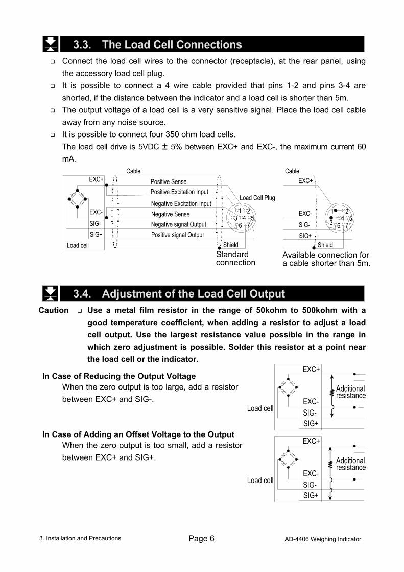
3.3. The Load Cell Connections Connect the load cell wires to the connector (receptacle), at the rear panel, using
the accessory load cell plug. It is possible to connect a 4 wire cable provided that pins 1-2 and pins 3-4 are
shorted, if the distance between the indicator and a load cell is shorter than 5m. The output voltage of a load cell is a very sensitive signal. Place the load cell cable
away from any noise source. It is possible to connect four 350 ohm load cells.
The load cell drive is 5VDC 5% between EXC+ and EXC-, the maximum current 60 mA.
3.4. Adjustment of the Load Cell Output Caution Use a metal film resistor in the range of 50kohm to 500kohm with a
good temperature coefficient, when adding a resistor to adjust a load cell output. Use the largest resistance value possible in the range in which zero adjustment is possible. Solder this resistor at a point near the load cell or the indicator.
In Case of Reducing the Output Voltage
When the zero output is too large, add a resistor between EXC+ and SIG-.
In Case of Adding an Offset Voltage to the Output When the zero output is too small, add a resistor
between EXC+ and SIG+.
3. Installation and Precautions
AD-4406 Weighing Indicator Page 7
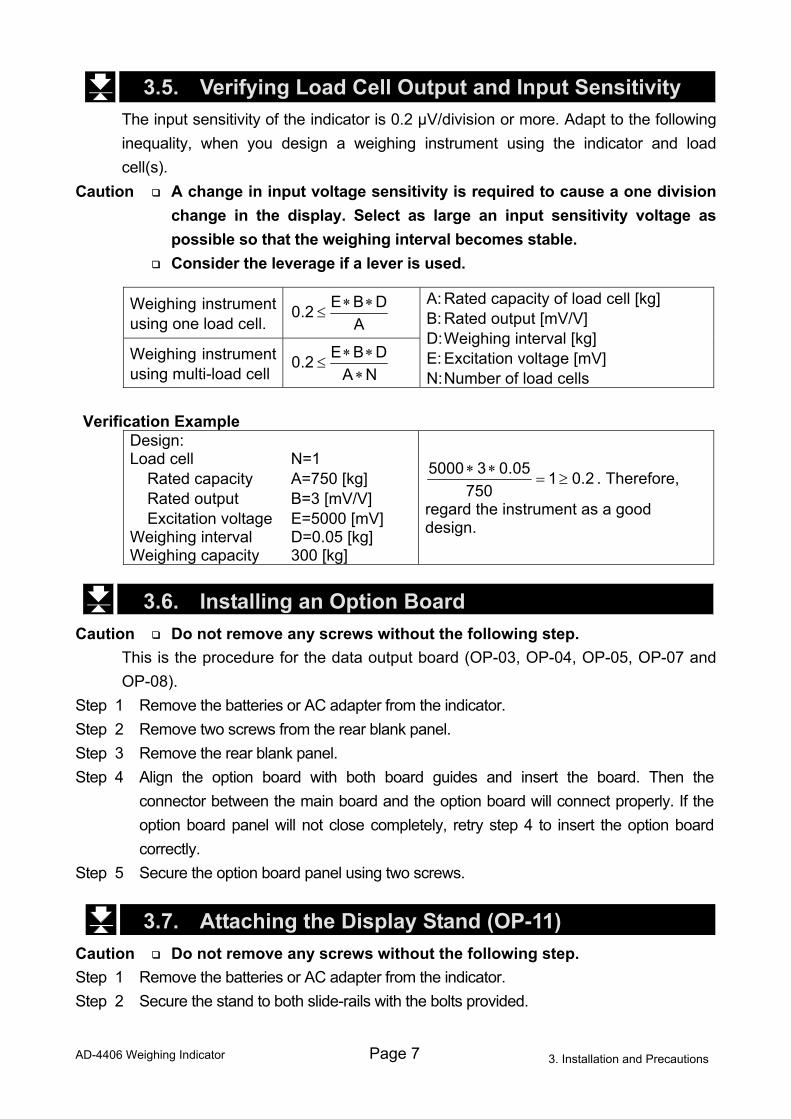
3.5. Verifying Load Cell Output and Input Sensitivity The input sensitivity of the indicator is 0.2 µV/division or more. Adapt to the following
inequality, when you design a weighing instrument using the indicator and load cell(s).
Caution A change in input voltage sensitivity is required to cause a one division change in the display. Select as large an input sensitivity voltage as possible so that the weighing interval becomes stable.
Consider the leverage if a lever is used.
Weighing instrument using one load cell. A
DBE2.0 ∗∗≤
Weighing instrument using multi-load cell NA
DBE2.0∗
∗∗≤
A: Rated capacity of load cell [kg] B: Rated output [mV/V] D: Weighing interval [kg] E: Excitation voltage [mV] N: Number of load cells
Verification Example
Design: Load cell N=1 Rated capacity A=750 [kg] Rated output B=3 [mV/V] Excitation voltage E=5000 [mV] Weighing interval D=0.05 [kg] Weighing capacity 300 [kg]
2.01750
05.035000≥=
∗∗ . Therefore,
regard the instrument as a good design.
3.6. Installing an Option Board
Caution Do not remove any screws without the following step. This is the procedure for the data output board (OP-03, OP-04, OP-05, OP-07 and
OP-08). Step 1 Remove the batteries or AC adapter from the indicator. Step 2 Remove two screws from the rear blank panel. Step 3 Remove the rear blank panel. Step 4 Align the option board with both board guides and insert the board. Then the
connector between the main board and the option board will connect properly. If the option board panel will not close completely, retry step 4 to insert the option board correctly.
Step 5 Secure the option board panel using two screws.
3.7. Attaching the Display Stand (OP-11) Caution Do not remove any screws without the following step. Step 1 Remove the batteries or AC adapter from the indicator. Step 2 Secure the stand to both slide-rails with the bolts provided.
3. Installation and Precautions
Page 8 AD-4406 Weighing Indicator
4. Description of Panels and Symbols
4.1. Front Panel Description
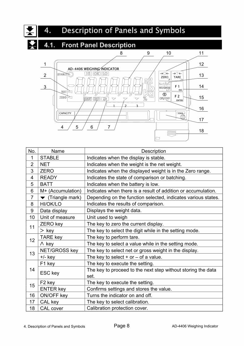
No. Name Description 1 STABLE Indicates when the display is stable. 2 NET Indicates when the weight is the net weight. 3 ZERO Indicates when the displayed weight is in the Zero range. 4 READY Indicates the state of comparison or batching. 5 BATT Indicates when the battery is low. 6 M+ (Accumulation) Indicates when there is a result of addition or accumulation. 7 (Triangle mark) Depending on the function selected, indicates various states.8 HI/OK/LO Indicates the results of comparison. 9 Data display Displays the weight data.
10 Unit of measure Unit used to weigh ZERO key The key to zero the current display. 11
key The key to select the digit while in the setting mode. TARE key The key to perform tare. 12
key The key to select a value while in the setting mode. NET/GROSS key The key to select net or gross weight in the display. 13 +/- key The key to select + or – of a value. F1 key The key to execute the setting.
14 ESC key The key to proceed to the next step without storing the data
set. F2 key The key to execute the setting. 15 ENTER key Confirms settings and stores the value.
16 ON/OFF key Turns the indicator on and off. 17 CAL key The key to select calibration. 18 CAL cover Calibration protection cover.
4. Description of Panels and Symbols
CAPACITY
AD-4406 WEIGHING INDICATOR
F 2 ENTER
+/
1 2 3
F 1 ESC
TARE ZERO
C A L .
1
8
2
3
9 10 11
12
4 5 6 7
13
14
15
16
17
18
AD-4406 Weighing Indicator Page 9
4.2. Rear Panel Description
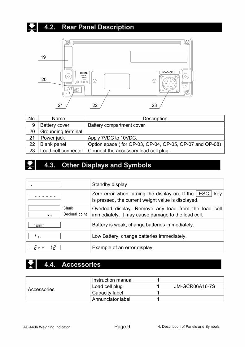
No. Name Description 19 Battery cover Battery compartment cover 20 Grounding terminal 21 Power jack Apply 7VDC to 10VDC. 22 Blank panel Option space ( for OP-03, OP-04, OP-05, OP-07 and OP-08)23 Load cell connector Connect the accessory load cell plug.
4.3. Other Displays and Symbols
Standby display
Zero error when turning the display on. If the ESC key is pressed, the current weight value is displayed.
Overload display. Remove any load from the load cell immediately. It may cause damage to the load cell.
Battery is weak, change batteries immediately.
Low Battery, change batteries immediately.
Example of an error display.
4.4. Accessories
Instruction manual 1 Load cell plug 1 JM-GCR06A16-7S Capacity label 1
Accessories
Annunciator label 1
BATT
LOAD CELL DC IN. 7-10V 100mA
20
21 22 23
19
4. Description of Panels and Symbols
Page 10 AD-4406 Weighing Indicator
5. Calibration The indicator converts an input voltage from a load cell to a "mass" value and
displays it. Calibration is the adjustment function so that the scale (indicator) can weigh correctly.
5.1. Items of the Calibration Mode
There are four items in the calibration mode. How to enter the calibration mode:
In the weighing mode, press the CAL key which is located behind the CAL cover at the lower right of the front panel. After CAL in is displayed for 2 seconds CAL 0 will appear. The required items should be selected and displayed with the ZERO key, then executed by pressing the ENTER key.
* The CAL cover is removed by sliding downward.
Required Items CALSEt Sets capacity, resolution, decimal point position and
display format, weighing range and unit. These items should be set first in order for the indicator to function as a weighing instrument. Set values do not need to be changed again unless the indicator itself is replaced. For details, refer to “5.2.1. Configuring a Weighing Instrument”.
CAL 0 Calibrates zero and span. This is required after installation, to get accurate data. For details, refer to “5.2.8. Zero Calibration” and “5.2.9. Span Calibration”.
Optional Items (Sub-functions)
Lnr 0 Performs digital linearization. Refer to “5.4. Digital Linearization Function”.
G SEt Compensates for acceleration of gravity. Refer to “5.5. Gravity Compensation Function”.
Gravity compensation function Compensates for weighing error between the calibration location and another weighing location using gravity acceleration.
In the calibration mode, the keys have functions as follows: When setting values, moves the cursor that is blinking. When setting values, increments the value or displays another setting. +/- Displays another setting. ESC Proceeds to the next step without changing the set value. ENTER Stores the set value and then proceeds to the next step.
5. Calibration
AD-4406 Weighing Indicator Page 11
CAL Writes all the set data into non-volatile memory and displays CALoFF. Then, press the ON/OFF key to turn the indicator off. Note that the ON/OFF key does not function alone in the calibration mode. When a value is mistakenly set, press the ESC key while holding the ON/OFF key to finish the calibration mode without storing the value. After CAnCEL is displayed, press the ON/OFF key to exit from the calibration mode and turns the indicator off.
Caution The maximum display is less than or equal to 40000 divisions. This number
is calculated from the maximum capacity divided by the minimum division. Check the accuracy of weighing instrument periodically. Recommended mass, use a mass heavier than 2/3 maximum capacity. Calibrate the scale, if it is moved to another location or the environment
has changed. It is not necessary to set the gravity acceleration correction, when calibrating
the scale with a calibration mass at the place where the scale is used. Enter the stable weight data while the STABLE mark is displayed. If
unstable data is used, it may cause a weighing error. Arrange the condition using the F00 filter function.
The span calibration needs the zero calibration data. We recommend that you perform the span calibration immediately after the zero calibration.
If you use the dual range function of the multi-interval scale, perform the "Range Function", "Zero Calibration" and "Span Calibration".
5.2. Calibration Procedure 5.2.1. Configuring a Weighing Instrument
This section explains how to specify the capacity, resolution, decimal point position and display format, weighing range and unit. Perform this procedure when installing the indicator. When CALSEt is displayed, enter this mode by pressing the ENTER key. Specify the range and unit. Single Range Specify the resolution, decimal point position and format. ↓ Specify the weighing capacity.
5. Calibration
Page 12 AD-4406 Weighing Indicator
Dual Range <First range> Specify the resolution, decimal point position and format.
↓ <First range> Specify the weighing range. ↓ <Second range> Specify the resolution. ↓ <Second range> Specify the weighing capacity. For the range function, refer to “5.3. Weighing Range Function”. 5.2.2. Specifying the Range and Unit
Step1 The range and unit of measure are displayed. Range display : SinGL : single range dUAL : dual range To change the range function, use the key Unit display The active unit is displayed. The unit can be changed;
such as kg or lb. Calibration is performed using the unit displayed.
Press the key to select a unit. Press the +/- key to select a unit for calibration. The unit for
calibration (first unit) is displayed and the alternate unit (second unit) is blinking.
ENTER The key to store the data displayed and proceed to the next step. ESC The key to proceed to the next step without changing the data. 5.2.3. Specifying the Resolution, Decimal Point Position and Format
Step 2 The resolution will be displayed as d 0.1 with decimal point. The indicator displays triangle 1 and the first unit selected at the previous step. Specify the position of the decimal point with the key. Specify the display format (point or comma) with the +/- key. Specify the resolution with the 1 key. The decimal point format for serial data output is selected using the F-function settings. Press the ENTER key to store the parameters and proceed to the next step. When pressing the ESC key, regardless of what is displayed, the indicator will proceed to the next step without changing the parameters.
5.2. Calibration Procedure
AD-4406 Weighing Indicator Page 13
5.2.4. Specifying the Weighing Range of the First Range
Step 3 After displaying CAP for 2 seconds, single range or the weighing capacity will be displayed. When dual range is used, CAP1 is displayed for 2 seconds. Triangle 1 will be displayed. Specify the range or the capacity with the and keys.
Press the ENTER key to store the parameter and proceed to the next step. When pressing the ESC key, regardless of what is displayed, the indicator will
proceed to the next step without changing the parameter. The next step is zero calibration in single range or specifying the second range resolution in dual range.
5.2.5. Specifying the Second Range Resolution
Step 4 After displaying rAnGE2 for 2 seconds, the resolution with decimal point and triangle 2 will be displayed. Specify the second range resolution in the same way as the first range. The decimal point cannot be moved. Specify the second range resolution greater than the first range.
Press the ENTER key to store the parameter and proceed to the next step. When pressing the ESC key, regardless of what is displayed, the indicator will
proceed to the next step without changing the parameter. 5.2.6. Specifying the Second Range Capacity
Step 5 After displaying CAP2 for 2 seconds, the capacity with unit and decimal point will be displayed. Specify the capacity in the same way as the first range. The capactity should be greater than the first range.
Press the ENTER key to store the parameter and proceed to zero calibration. When pressing the ESC key, regardless of what is displayed, the indicator will
proceed to zero calibration without changing the parameter. 5.2.7. To Get Stabilized Data
Step 6 Maintain the following conditions to calibrate the scale (indicator) correctly. Maintain a constant temperature, stable power and stable input voltage from the
load cell. Avoid direct sunshine or near the outlet of an air conditioner. Do not install the scale (indicator) where there is a strong magnetic field. Step 7 Turn the display on and leave it for several minutes.
5.2. Calibration Procedure
Page 14 AD-4406 Weighing Indicator
F 2 ENTER
F 2 ENTER
Stored input voltage
New input voltage
mV/V +/-
ZERO TARE
mV/V
Place nothing on the weighing unit
(No load) Turn on STABLE mark
Zero calibration
To Span Calibration
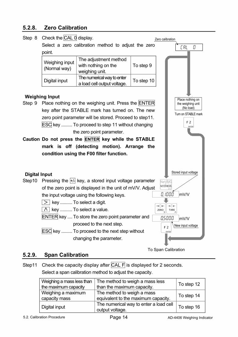
5.2.8. Zero Calibration
Step 8 Check the CAL 0 display. Select a zero calibration method to adjust the zero point.
Weighing input (Normal way)
The adjustment method with nothing on the weighing unit.
To step 9
Digital input The numerical way to enter a load cell output voltage. To step 10
Weighing Input
Step 9 Place nothing on the weighing unit. Press the ENTER key after the STABLE mark has turned on. The new zero point parameter will be stored. Proceed to step11.
ESC key ......... To proceed to step 11 without changing the zero point parameter.
Caution Do not press the ENTER key while the STABLE mark is off (detecting motion). Arrange the condition using the F00 filter function.
Digital Input
Step10 Pressing the +/- key, a stored input voltage parameter of the zero point is displayed in the unit of mV/V. Adjust the input voltage using the following keys.
key .......... To select a digit. key .......... To select a value. ENTER key .... To store the zero point parameter and
proceed to the next step. ESC key ......... To proceed to the next step without
changing the parameter.
5.2.9. Span Calibration
Step11 Check the capacity display after CAL F is displayed for 2 seconds. Select a span calibration method to adjust the capacity.
Weighing a mass less than the maximum capacity
The method to weigh a mass less than the maximum capacity. To step 12
Weighing a maximum capacity mass
The method to weigh a mass equivalent to the maximum capacity. To step 14
Digital input The numerical way to enter a load cell output voltage. To step 16
5.2. Calibration Procedure
AD-4406 Weighing Indicator Page 15
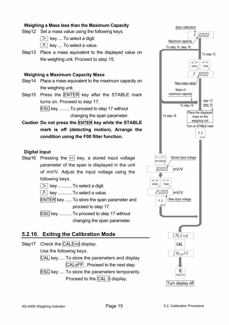
Weighing a Mass less than the Maximum Capacity Step12 Set a mass value using the following keys. key .... To select a digit. key .... To select a value. Step13 Place a mass equivalent to the displayed value on
the weighing unit. Proceed to step 15.
Weighing a Maximum Capacity Mass Step14 Place a mass equivalent to the maximum capacity on
the weighing unit. Step15 Press the ENTER key after the STABLE mark
turns on. Proceed to step 17. ESC key ......... To proceed to step 17 without
changing the span parameter. Caution Do not press the ENTER key while the STABLE
mark is off (detecting motion). Arrange the condition using the F00 filter function.
Digital Input Step16 Pressing the +/- key, a stored input voltage
parameter of the span is displayed in the unit of mV/V. Adjust the input voltage using the following keys.
key ............ To select a digit. key ............ To select a value. ENTER key ...... To store the span parameter and
proceed to step 17. ESC key ........... To proceed to step 17 without
changing the span parameter. 5.2.10. Exiting the Calibration Mode
Step17 Check the CALEnd display. Use the following keys. CAL key..... To store the parameters and display
CALoFF . Proceed to the next step. ESC key .... To store the parameters temporarily.
Proceed to the CAL 0 display. 5.2. Calibration Procedure
Turn on STABLE mark
Span calibration
Maximum capacity To step 14, step 16
To step 12
ZERO TARE
New mass value
Mass of maximum capacity
To step 14
To step 16 Place the displayed
mass on the weighing unit
step 13 step 14
F 2ENTER
Stored input voltage
New input voltage
mV/V +/-
ZERO TARE
F 2 ENTER
mV/V
Turn display off
Page 16 AD-4406 Weighing Indicator
Press and hold the ON/OFF key and press the ESC key. No parameters are changed, CAnCEL is displayed and the calibration mode is finished. Step18 Press the ON/OFF key to turn the display off.
5.3. Weighing Range Function The weighing range function can select "single range" or "dual range". Specify each
weighing interval (division) for the multi-interval instrument. Each weighing interval is displayed according to a net value or gross value.
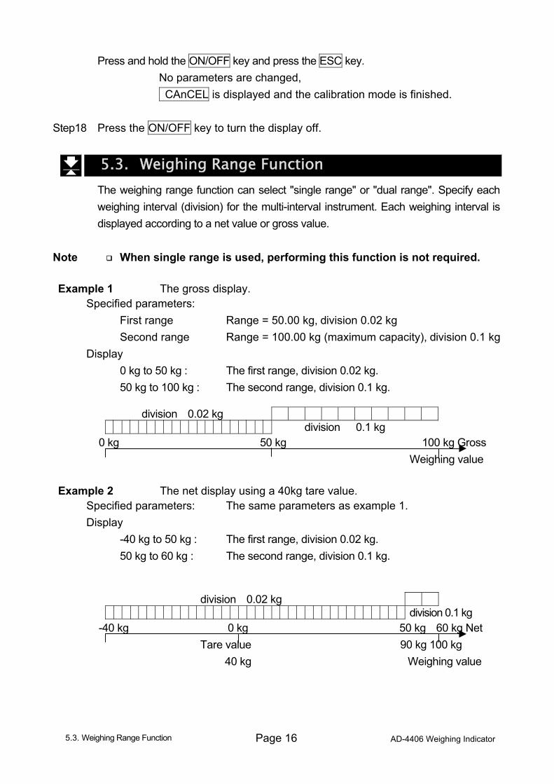
Note When single range is used, performing this function is not required. Example 1 The gross display.
Specified parameters: First range Range = 50.00 kg, division 0.02 kg Second range Range = 100.00 kg (maximum capacity), division 0.1 kg Display 0 kg to 50 kg : The first range, division 0.02 kg. 50 kg to 100 kg : The second range, division 0.1 kg.
division 0.02 kg division 0.1 kg
0 kg 50 kg 100 kg Gross
Weighing value
Example 2 The net display using a 40kg tare value.
Specified parameters: The same parameters as example 1. Display -40 kg to 50 kg : The first range, division 0.02 kg. 50 kg to 60 kg : The second range, division 0.1 kg.
division 0.02 kg division 0.1 kg
-40 kg 0 kg 50 kg 60 kg Net Tare value 90 kg 100 kg 40 kg Weighing value
5.3. Weighing Range Function
AD-4406 Weighing Indicator Page 17
5.3.1. Setting the Division and Range
Consider the following rules to design the weighing range. Rule 1 Select the division and range of each weighing range so as to fit the following inequality. The first range < the second range The division of the next weighing range is automatically set larger than the division
of the lower weighing range. Rule 2 When setting the dual range, the upper limit value of the second range becomes
the maximum capacity. Rule 3 Select a resolution smaller than 40000. The resolution is a value obtained by
dividing the maximum capacity by the minimum division of the first range.
5.4. Digital Linearization Function Even if the zero and span calibration have been completed, there may still remain a
linearity deviation caused by the performance of the weighing unit. The digital linearization function can rectify or reduce the linearity deviation using weighing points during the zero and capacity setting. Up to three weighing points can be specified.
Caution This function does not improve repeatability or hysteresis. Use the mass on the condition that Lnr 1 < Lnr 2 < Lnr 3. Do not press the ENTER key while the STABLE mark is off. Step 1 Check the CAL 0 display. Press the key to display Lnr 0. Step 2 Enter the zero point. Refer to “5.2.8. Zero Calibration”. Step 3 The value of the middle point is displayed after indicating Lnr x. x is 1, 2 or 3. The mark of the same number (x) is displayed along with the value. Step 4 Select a middle point. If you want to cancel the current procedure, press the ESC key to finish this
function. Proceed to step 7. The other points are cleared (canceled). Select a middle point value using the following keys. Proceed to step 5. key...........To select a digit. key ...........To select a value. Step 5 Place a mass equivalent to the displayed value on the weighing unit. Press the
ENTER key after the STABLE mark has turned on. Proceed to step 6. Step 6 If you include a 2nd and 3rd middle point, repeat steps 3, 4, 5 for each.
If you finish this function, proceed to step 7. Step 7 Perform step 11 of "5.2.9. Span Calibration" immediately.
5.4. Digital Linearization Function
Page 18 AD-4406 Weighing Indicator
5.5. Gravity Compensation Function If the scale is used at the calibration location, it is not necessary to perform this function. If there is a difference in the gravity acceleration between the calibration location
and the installed location, it may cause a weighing error. This function specifies these gravity accelerations and corrects the span error.
Note The decimal point is not displayed in the function. Example: 9798 = 9.798 m/s2
When span calibration is executed, the gravity acceleration correction will be cleared and two gravity acceleration values will return to the factory settings.
Step 1 At the CAL 0 display, press the key until G SEt is displayed and press the
ENTER key to enter the gravity compensation function. If you want to cancel the current procedure, press and hold the ON/OFF key and
press the ESC key to display CAnCEL. Then, no parameters are changed and the calibration mode is finished. Press the ON/OFF key to turn the display off.
Step 2 The parameter is displayed with triangle 1. Enter the gravity acceleration of the
calibration location. The parameter xxxx is the gravity acceleration. key....... To select a digit. key ....... To select a value. ENTER key .. To store the new gravity acceleration and proceed to step 3. ESC key....... To return to G SEt without changing the value. Step 3 The parameter is displayed with triangle 2. Enter the gravity acceleration of the
installed location. The parameter xxxx is the gravity acceleration. key ...... To select a digit. key....... To select a value. ENTER key . To store the new gravity acceleration and proceed to step 4. ESC key ...... To return to step 2 without changing the value. Step 4 Now G xxxx is displayed. Press the CAL key to store the parameters. CALoFF is
displayed. Proceed to step 5. Step 5 Press the ON/OFF key to turn the display off.
5.5. Gravity Compensation Function
AD-4406 Weighing Indicator Page 19
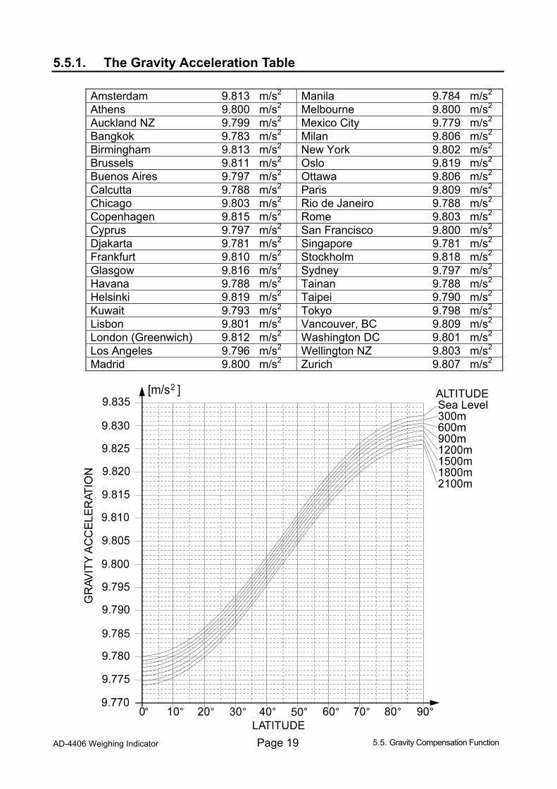
5.5.1. The Gravity Acceleration Table
Amsterdam 9.813 m/s2 Manila 9.784 m/s2 Athens 9.800 m/s2 Melbourne 9.800 m/s2 Auckland NZ 9.799 m/s2 Mexico City 9.779 m/s2 Bangkok 9.783 m/s2 Milan 9.806 m/s2 Birmingham 9.813 m/s2 New York 9.802 m/s2 Brussels 9.811 m/s2 Oslo 9.819 m/s2 Buenos Aires 9.797 m/s2 Ottawa 9.806 m/s2 Calcutta 9.788 m/s2 Paris 9.809 m/s2 Chicago 9.803 m/s2 Rio de Janeiro 9.788 m/s2 Copenhagen 9.815 m/s2 Rome 9.803 m/s2 Cyprus 9.797 m/s2 San Francisco 9.800 m/s2 Djakarta 9.781 m/s2 Singapore 9.781 m/s2 Frankfurt 9.810 m/s2 Stockholm 9.818 m/s2 Glasgow 9.816 m/s2 Sydney 9.797 m/s2 Havana 9.788 m/s2 Tainan 9.788 m/s2 Helsinki 9.819 m/s2 Taipei 9.790 m/s2 Kuwait 9.793 m/s2 Tokyo 9.798 m/s2 Lisbon 9.801 m/s2 Vancouver, BC 9.809 m/s2 London (Greenwich) 9.812 m/s2 Washington DC 9.801 m/s2 Los Angeles 9.796 m/s2 Wellington NZ 9.803 m/s2 Madrid 9.800 m/s2 Zurich 9.807 m/s2
5.5. Gravity Compensation Function
Page 20 AD-4406 Weighing Indicator
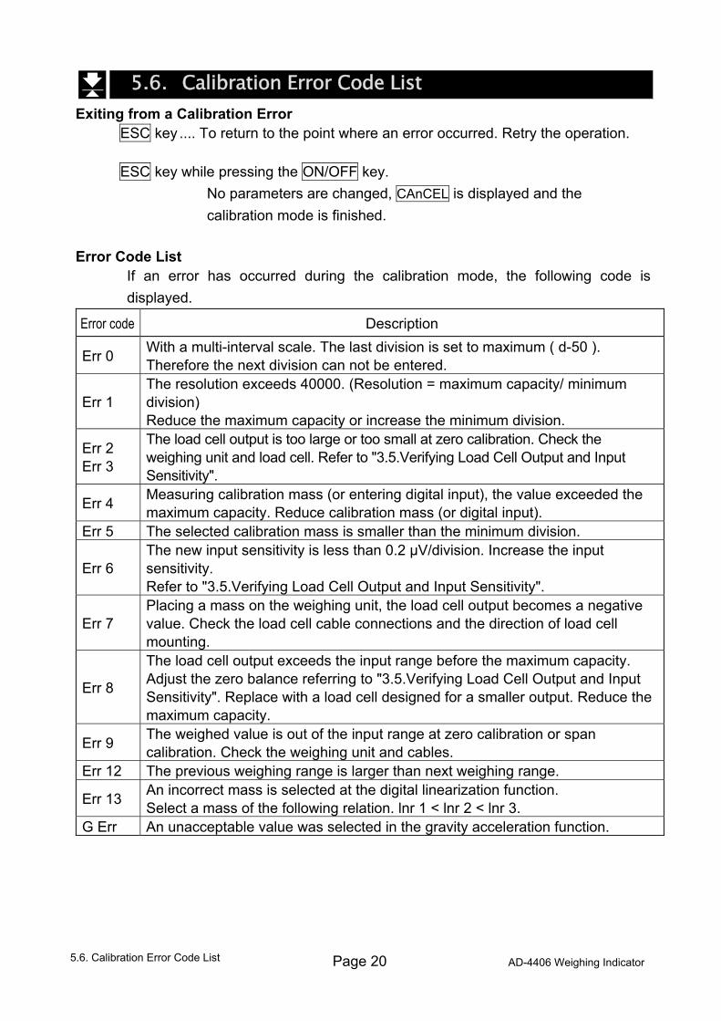
5.6. Calibration Error Code List Exiting from a Calibration Error
ESC key .... To return to the point where an error occurred. Retry the operation. ESC key while pressing the ON/OFF key. No parameters are changed, CAnCEL is displayed and the
calibration mode is finished. Error Code List
If an error has occurred during the calibration mode, the following code is displayed.
Error code Description
Err 0 With a multi-interval scale. The last division is set to maximum ( d-50 ). Therefore the next division can not be entered.
Err 1 The resolution exceeds 40000. (Resolution = maximum capacity/ minimum division) Reduce the maximum capacity or increase the minimum division.
Err 2 Err 3
The load cell output is too large or too small at zero calibration. Check the weighing unit and load cell. Refer to "3.5.Verifying Load Cell Output and Input Sensitivity".
Err 4 Measuring calibration mass (or entering digital input), the value exceeded the maximum capacity. Reduce calibration mass (or digital input).
Err 5 The selected calibration mass is smaller than the minimum division.
Err 6 The new input sensitivity is less than 0.2 µV/division. Increase the input sensitivity. Refer to "3.5.Verifying Load Cell Output and Input Sensitivity".
Err 7 Placing a mass on the weighing unit, the load cell output becomes a negative value. Check the load cell cable connections and the direction of load cell mounting.
Err 8
The load cell output exceeds the input range before the maximum capacity. Adjust the zero balance referring to "3.5.Verifying Load Cell Output and Input Sensitivity". Replace with a load cell designed for a smaller output. Reduce the maximum capacity.
Err 9 The weighed value is out of the input range at zero calibration or span calibration. Check the weighing unit and cables.
Err 12 The previous weighing range is larger than next weighing range.
Err 13 An incorrect mass is selected at the digital linearization function. Select a mass of the following relation. lnr 1 < lnr 2 < lnr 3.
G Err An unacceptable value was selected in the gravity acceleration function.
5.6. Calibration Error Code List
AD-4406 Weighing Indicator Page 21
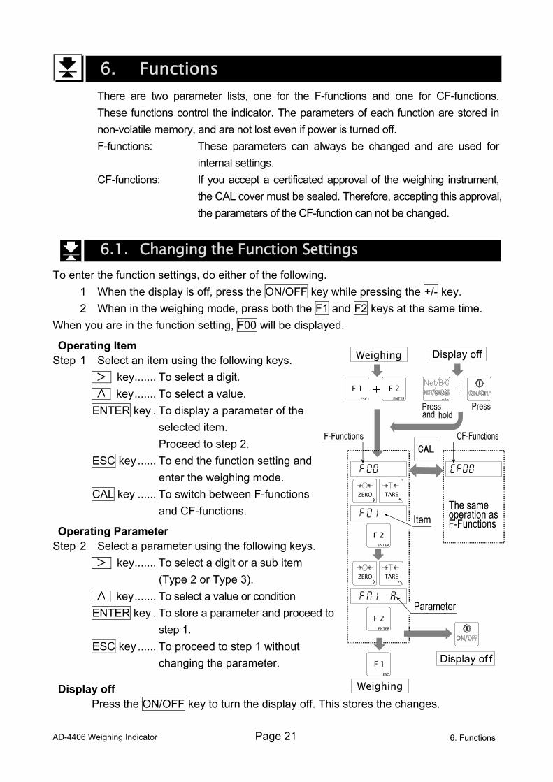
6. Functions There are two parameter lists, one for the F-functions and one for CF-functions.
These functions control the indicator. The parameters of each function are stored in non-volatile memory, and are not lost even if power is turned off.
F-functions: These parameters can always be changed and are used for internal settings.
CF-functions: If you accept a certificated approval of the weighing instrument, the CAL cover must be sealed. Therefore, accepting this approval, the parameters of the CF-function can not be changed.
6.1. Changing the Function Settings To enter the function settings, do either of the following. 1 When the display is off, press the ON/OFF key while pressing the +/- key. 2 When in the weighing mode, press both the F1 and F2 keys at the same time. When you are in the function setting, F00 will be displayed.
Operating Item Step 1 Select an item using the following keys. key....... To select a digit. key....... To select a value. ENTER key . To display a parameter of the
selected item. Proceed to step 2.
ESC key ...... To end the function setting and enter the weighing mode.
CAL key ...... To switch between F-functions and CF-functions.
Operating Parameter Step 2 Select a parameter using the following keys. key....... To select a digit or a sub item
(Type 2 or Type 3). key....... To select a value or condition ENTER key . To store a parameter and proceed to
step 1. ESC key ...... To proceed to step 1 without
changing the parameter.
Display off Press the ON/OFF key to turn the display off. This stores the changes.
6. Functions
+/-
F 2 ENTER
F 1ESC
Weighing
Weighing
ZERO TARE
ZERO TARE
F 2ENTER
F 2ENTER
F 1ESC
Page 22 AD-4406 Weighing Indicator
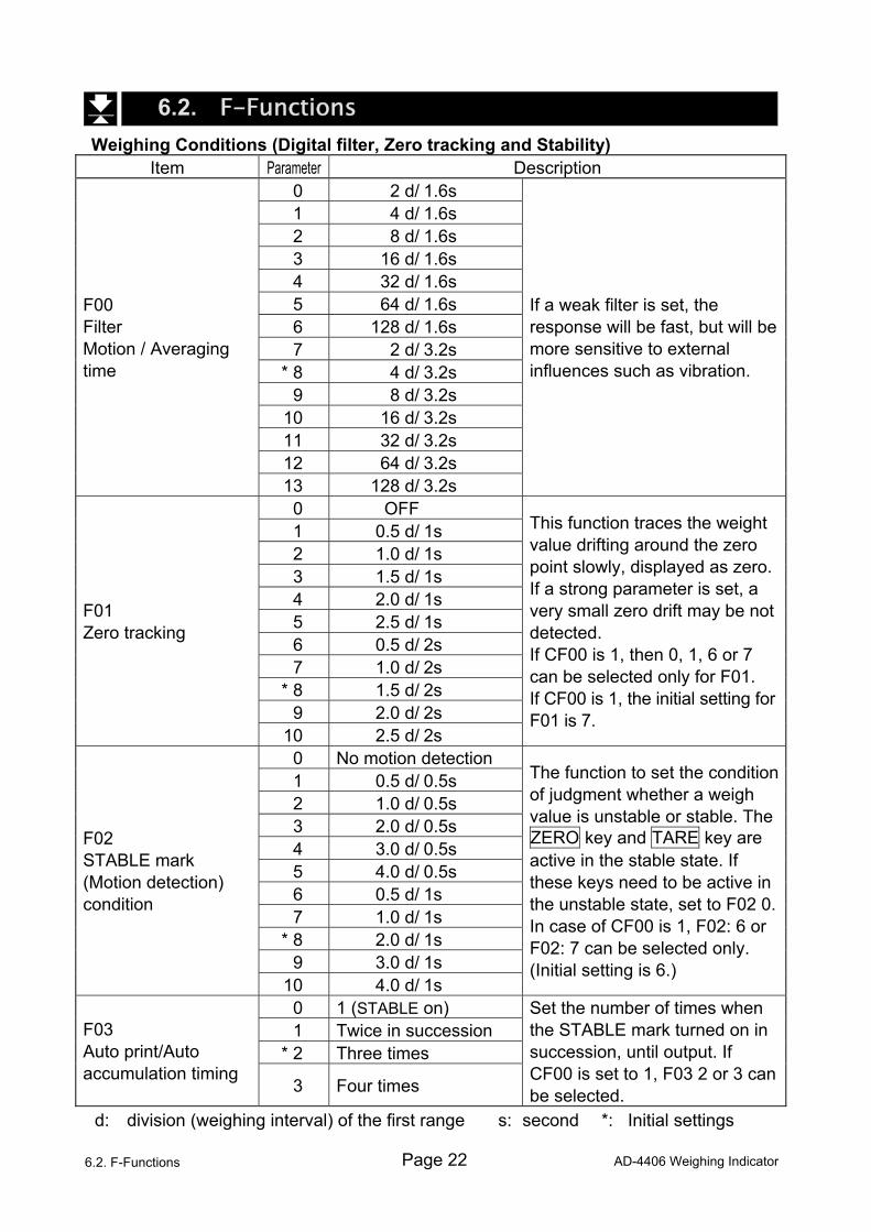
6.2. F-Functions Weighing Conditions (Digital filter, Zero tracking and Stability)
Item Parameter Description 0 2 d/ 1.6s 1 4 d/ 1.6s 2 8 d/ 1.6s 3 16 d/ 1.6s 4 32 d/ 1.6s 5 64 d/ 1.6s 6 128 d/ 1.6s 7 2 d/ 3.2s
* 8 4 d/ 3.2s 9 8 d/ 3.2s
10 16 d/ 3.2s 11 32 d/ 3.2s 12 64 d/ 3.2s
F00 Filter Motion / Averaging time
13 128 d/ 3.2s
If a weak filter is set, the response will be fast, but will be more sensitive to external influences such as vibration.
0 OFF 1 0.5 d/ 1s 2 1.0 d/ 1s 3 1.5 d/ 1s 4 2.0 d/ 1s 5 2.5 d/ 1s 6 0.5 d/ 2s 7 1.0 d/ 2s
* 8 1.5 d/ 2s 9 2.0 d/ 2s
F01 Zero tracking
10 2.5 d/ 2s
This function traces the weight value drifting around the zero point slowly, displayed as zero. If a strong parameter is set, a very small zero drift may be not detected. If CF00 is 1, then 0, 1, 6 or 7 can be selected only for F01. If CF00 is 1, the initial setting for F01 is 7.
0 No motion detection 1 0.5 d/ 0.5s 2 1.0 d/ 0.5s 3 2.0 d/ 0.5s 4 3.0 d/ 0.5s 5 4.0 d/ 0.5s 6 0.5 d/ 1s 7 1.0 d/ 1s
* 8 2.0 d/ 1s 9 3.0 d/ 1s
F02 STABLE mark (Motion detection) condition
10 4.0 d/ 1s
The function to set the condition of judgment whether a weigh value is unstable or stable. The ZERO key and TARE key are active in the stable state. If these keys need to be active in the unstable state, set to F02 0. In case of CF00 is 1, F02: 6 or F02: 7 can be selected only. (Initial setting is 6.)
0 1 (STABLE on) 1 Twice in succession
* 2 Three times F03 Auto print/Auto accumulation timing
3 Four times
Set the number of times when the STABLE mark turned on in succession, until output. If CF00 is set to 1, F03 2 or 3 can be selected.
d: division (weighing interval) of the first range s: second *: Initial settings
6.2. F-Functions
AD-4406 Weighing Indicator Page 23
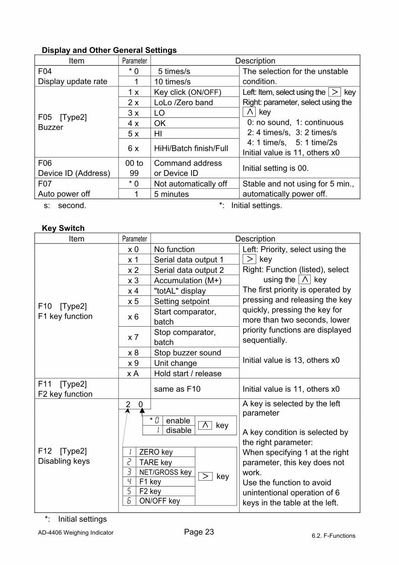
Display and Other General Settings
Item Parameter Description * 0 5 times/s F04
Display update rate 1 10 times/s The selection for the unstable condition.
1 x Key click (ON/OFF) 2 x LoLo /Zero band
3 x LO 4 x OK 5 x HI
F05 [Type2] Buzzer
6 x HiHi/Batch finish/Full
Left: Item, select using the keyRight: parameter, select using the 1 key 0: no sound, 1: continuous 2: 4 times/s, 3: 2 times/s 4: 1 time/s, 5: 1 time/2s
Initial value is 11, others x0 F06 Device ID (Address)
00 to 99
Command address or Device ID Initial setting is 00.
* 0 Not automatically off F07 Auto power off 1 5 minutes
Stable and not using for 5 min., automatically power off.
s: second. *: Initial settings. Key Switch
Item Parameter Description x 0 No function x 1 Serial data output 1 x 2 Serial data output 2 x 3 Accumulation (M+) x 4 "totAL" display x 5 Setting setpoint
x 6 Start comparator, batch
x 7 Stop comparator, batch
x 8 Stop buzzer sound x 9 Unit change
F10 [Type2] F1 key function
x A Hold start / release
Left: Priority, select using the 1 key Right: Function (listed), select
using the key The first priority is operated by pressing and releasing the key quickly, pressing the key for more than two seconds, lower priority functions are displayed sequentially. Initial value is 13, others x0
F11 [Type2] F2 key function same as F10 Initial value is 11, others x0
2 0
F12 [Type2] Disabling keys
A key is selected by the left parameter A key condition is selected by the right parameter: When specifying 1 at the right parameter, this key does not work. Use the function to avoid unintentional operation of 6 keys in the table at the left.
*: Initial settings
* 0 enable1 disable key
1 ZERO key 2 TARE key 3 NET/GROSS key4 F1 key 5 F2 key 6 ON/OFF key
key
6.2. F-Functions
Page 24 AD-4406 Weighing Indicator
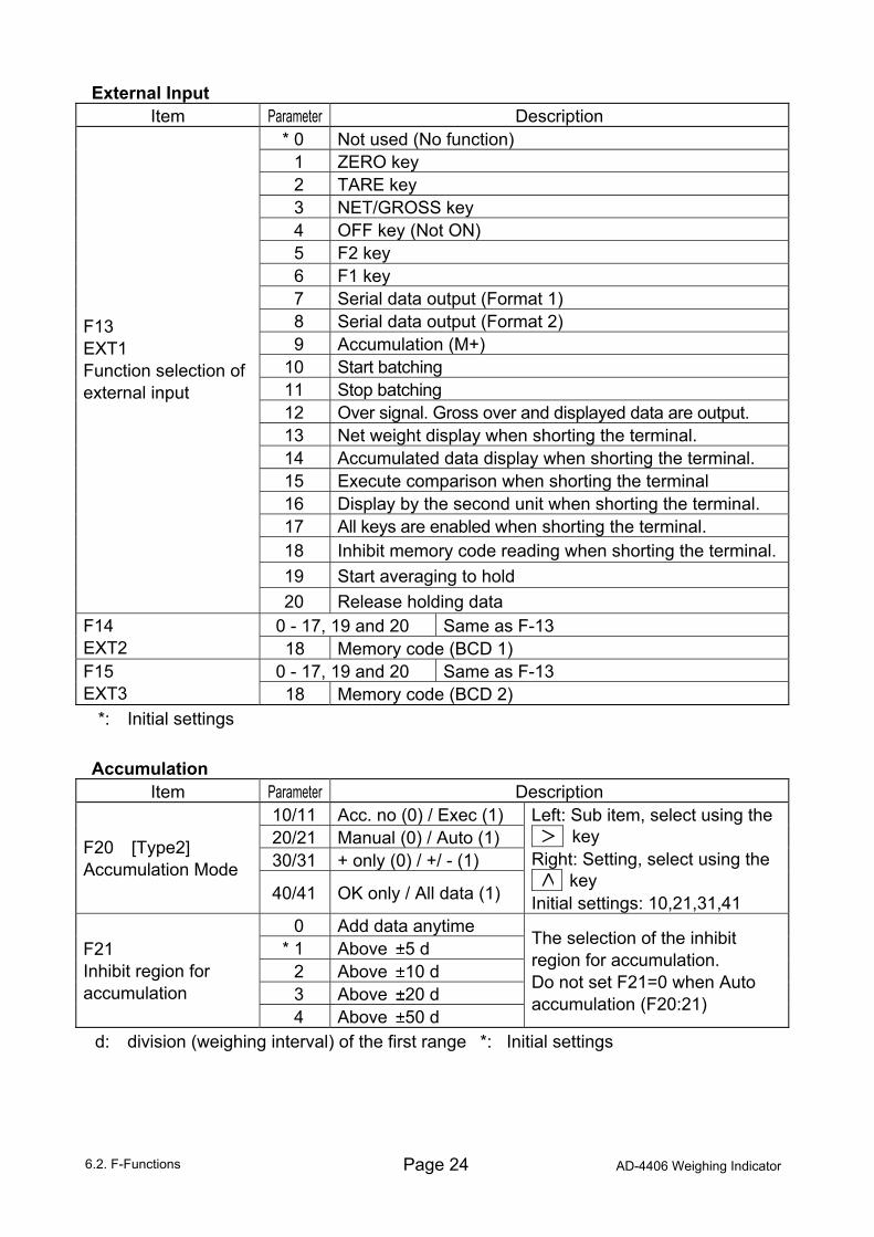
External Input Item Parameter Description
* 0 Not used (No function) 1 ZERO key 2 TARE key 3 NET/GROSS key 4 OFF key (Not ON) 5 F2 key 6 F1 key 7 Serial data output (Format 1) 8 Serial data output (Format 2) 9 Accumulation (M+)
10 Start batching 11 Stop batching 12 Over signal. Gross over and displayed data are output. 13 Net weight display when shorting the terminal. 14 Accumulated data display when shorting the terminal. 15 Execute comparison when shorting the terminal 16 Display by the second unit when shorting the terminal. 17 All keys are enabled when shorting the terminal. 18 Inhibit memory code reading when shorting the terminal.19 Start averaging to hold
F13 EXT1 Function selection of external input
20 Release holding data 0 - 17, 19 and 20 Same as F-13 F14
EXT2 18 Memory code (BCD 1) 0 - 17, 19 and 20 Same as F-13 F15
EXT3 18 Memory code (BCD 2) *: Initial settings Accumulation
Item Parameter Description 10/11 Acc. no (0) / Exec (1) 20/21 Manual (0) / Auto (1) 30/31 + only (0) / +/ - (1)
F20 [Type2] Accumulation Mode
40/41 OK only / All data (1)
Left: Sub item, select using the 1 key Right: Setting, select using the 1 key Initial settings: 10,21,31,41
0 Add data anytime * 1 Above 5 d
2 Above 10 d 3 Above 20 d
F21 Inhibit region for accumulation
4 Above 50 d
The selection of the inhibit region for accumulation. Do not set F21=0 when Auto accumulation (F20:21)
d: division (weighing interval) of the first range *: Initial settings
6.2. F-Functions
AD-4406 Weighing Indicator Page 25
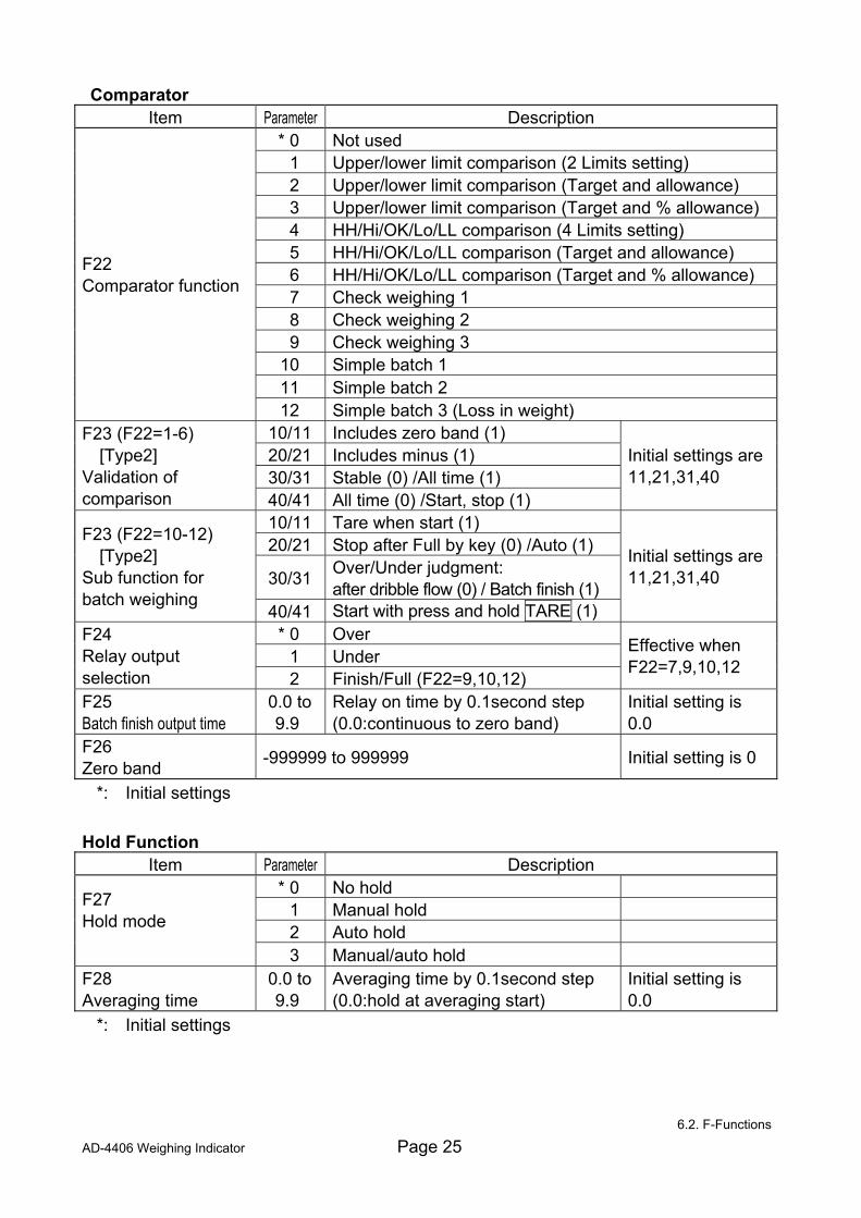
Comparator Item Parameter Description
* 0 Not used 1 Upper/lower limit comparison (2 Limits setting) 2 Upper/lower limit comparison (Target and allowance) 3 Upper/lower limit comparison (Target and % allowance) 4 HH/Hi/OK/Lo/LL comparison (4 Limits setting) 5 HH/Hi/OK/Lo/LL comparison (Target and allowance) 6 HH/Hi/OK/Lo/LL comparison (Target and % allowance) 7 Check weighing 1 8 Check weighing 2 9 Check weighing 3
10 Simple batch 1 11 Simple batch 2
F22 Comparator function
12 Simple batch 3 (Loss in weight) 10/11 Includes zero band (1) 20/21 Includes minus (1) 30/31 Stable (0) /All time (1)
F23 (F22=1-6) [Type2] Validation of comparison 40/41 All time (0) /Start, stop (1)
Initial settings are 11,21,31,40
10/11 Tare when start (1) 20/21 Stop after Full by key (0) /Auto (1)
30/31 Over/Under judgment: after dribble flow (0) / Batch finish (1)
F23 (F22=10-12) [Type2] Sub function for batch weighing
40/41 Start with press and hold TARE (1)
Initial settings are 11,21,31,40
* 0 Over 1 Under
F24 Relay output selection 2 Finish/Full (F22=9,10,12)
Effective when F22=7,9,10,12
F25 Batch finish output time
0.0 to 9.9
Relay on time by 0.1second step (0.0:continuous to zero band)
Initial setting is 0.0
F26 Zero band -999999 to 999999 Initial setting is 0
*: Initial settings Hold Function
Item Parameter Description * 0 No hold
1 Manual hold 2 Auto hold
F27 Hold mode
3 Manual/auto hold F28 Averaging time
0.0 to 9.9
Averaging time by 0.1second step (0.0:hold at averaging start)
Initial setting is 0.0
*: Initial settings
6.2. F-Functions
Page 26 AD-4406 Weighing Indicator
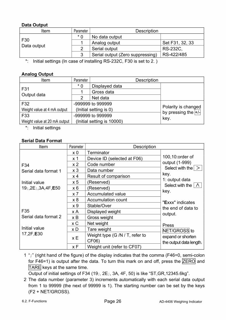
Data Output Item Parameter Description
* 0 No data output 1 Analog output Set F31, 32, 33 2 Serial output
F30 Data output
3 Serial output (Zero suppressing) RS-232C, RS-422/485
*: Initial settings (In case of installing RS-232C, F30 is set to 2. ) Analog Output
Item Parameter Description * 0 Displayed data
1 Gross data F31 Output data
2 Net data
F32 Weight value at 4 mA output
-999999 to 999999 (Initial setting is 0)
F33 Weight value at 20 mA output
-999999 to 999999 (Initial setting is 10000)
Polarity is changed by pressing the +/- key.
*: Initial settings Serial Data Format
Item Parameter Description x 0 Terminator x 1 Device ID (selected at F06) x 2 Code number x 3 Data number x 4 Result of comparison x 5 (Reserved) x 6 (Reserved) x 7 Accumulated value x 8 Accumulation count x 9 Stable/Over x A Displayed weight x B Gross weight x C Net weight x D Tare weight
x E Weight type (G /N / T, refer to CF06)
F34 Serial data format 1 Initial value 19」,2E」,3A,4F,E50 F35 Serial data format 2 Initial value 17,2F,E30
x F Weight unit (refer to CF07)
100,10:order of output (1-999) Select with the 1 1 key. 1: output data Select with the key. "Exxx" indicates the end of data to output. Press NET/GROSS to expand or shorten the output data length.
1 “」” (right hand of the figure) of the display indicates that the comma (F46=0, semi-colon for F46=1) is output after the data. To turn this mark on and off, press the ZERO and TARE keys at the same time.
Output of initial settings of F34 (19」, 2E」, 3A, 4F, 50) is like “ST,GR,12345.6kg”. 2 The data number (parameter 3) increments automatically with each serial data output
from 1 to 99999 (the next of 99999 is 1). The starting number can be set by the keys (F2 + NET/GROSS).
6.2. F-Functions
AD-4406 Weighing Indicator Page 27
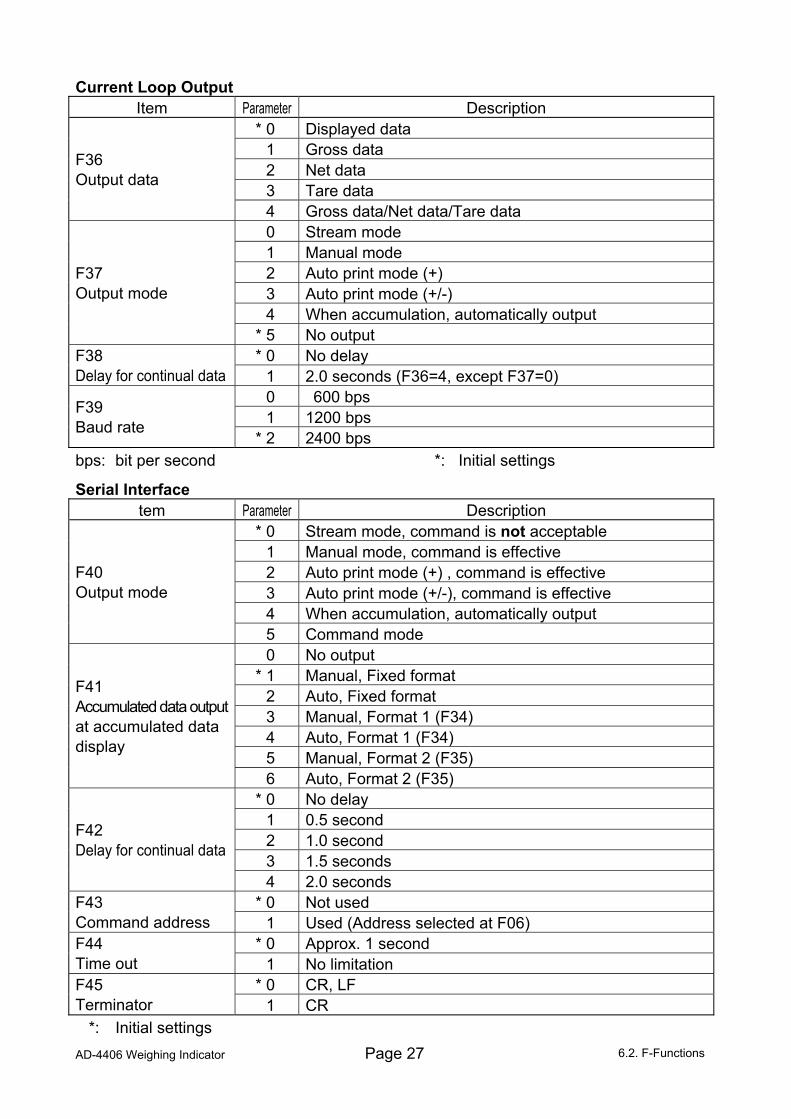
Current Loop Output Item Parameter Description
* 0 Displayed data 1 Gross data 2 Net data 3 Tare data
F36 Output data
4 Gross data/Net data/Tare data 0 Stream mode 1 Manual mode 2 Auto print mode (+) 3 Auto print mode (+/-) 4 When accumulation, automatically output
F37 Output mode
* 5 No output * 0 No delay F38
Delay for continual data 1 2.0 seconds (F36=4, except F37=0) 0 600 bps 1 1200 bps F39
Baud rate * 2 2400 bps
bps: bit per second *: Initial settings
Serial Interface tem Parameter Description
* 0 Stream mode, command is not acceptable 1 Manual mode, command is effective 2 Auto print mode (+) , command is effective 3 Auto print mode (+/-), command is effective 4 When accumulation, automatically output
F40 Output mode
5 Command mode 0 No output
* 1 Manual, Fixed format 2 Auto, Fixed format 3 Manual, Format 1 (F34) 4 Auto, Format 1 (F34) 5 Manual, Format 2 (F35)
F41 Accumulated data output at accumulated data display
6 Auto, Format 2 (F35) * 0 No delay
1 0.5 second 2 1.0 second 3 1.5 seconds
F42 Delay for continual data
4 2.0 seconds * 0 Not used F43
Command address 1 Used (Address selected at F06) * 0 Approx. 1 second F44
Time out 1 No limitation * 0 CR, LF F45
Terminator 1 CR
*: Initial settings 6.2. F-Functions
Page 28 AD-4406 Weighing Indicator
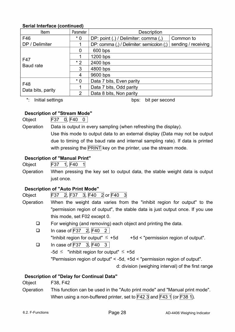
Serial Interface (continued) Item Parameter Description
* 0 DP: point (.) / Delimiter: comma (,) F46 DP / Delimiter 1 DP: comma (,) / Delimiter: semicolon (;)
Common to sending / receiving
0 600 bps 1 1200 bps
* 2 2400 bps 3 4800 bps
F47 Baud rate
4 9600 bps * 0 Data 7 bits, Even parity
1 Data 7 bits, Odd parity F48 Data bits, parity
2 Data 8 bits, Non parity *: Initial settings bps: bit per second Description of "Stream Mode"
Object F37 0, F40 0 Operation Data is output in every sampling (when refreshing the display). Use this mode to output data to an external display (Data may not be output
due to timing of the baud rate and internal sampling rate). If data is printed with pressing the PRINT key on the printer, use the stream mode.
Description of "Manual Print" Object F37 1, F40 1 Operation When pressing the key set to output data, the stable weight data is output
just once.
Description of "Auto Print Mode" Object F37 2, F37 3, F40 2 or F40 3 Operation When the weight data varies from the "inhibit region for output" to the
"permission region of output", the stable data is just output once. If you use this mode, set F02 except 0.
For weighing (and removing) each object and printing the data. In case of F37 2, F40 2 "Inhibit region for output" +5d +5d < "permission region of output". In case of F37 3, F40 3 -5d "inhibit region for output" +5d "Permission region of output" < -5d, +5d < "permission region of output".
d: division (weighing interval) of the first range
Description of "Delay for Continual Data" Object F38, F42 Operation This function can be used in the "Auto print mode" and "Manual print mode". When using a non-buffered printer, set to F42 3 and F43 1 (or F38 1).
6.2. F-Functions
AD-4406 Weighing Indicator Page 29
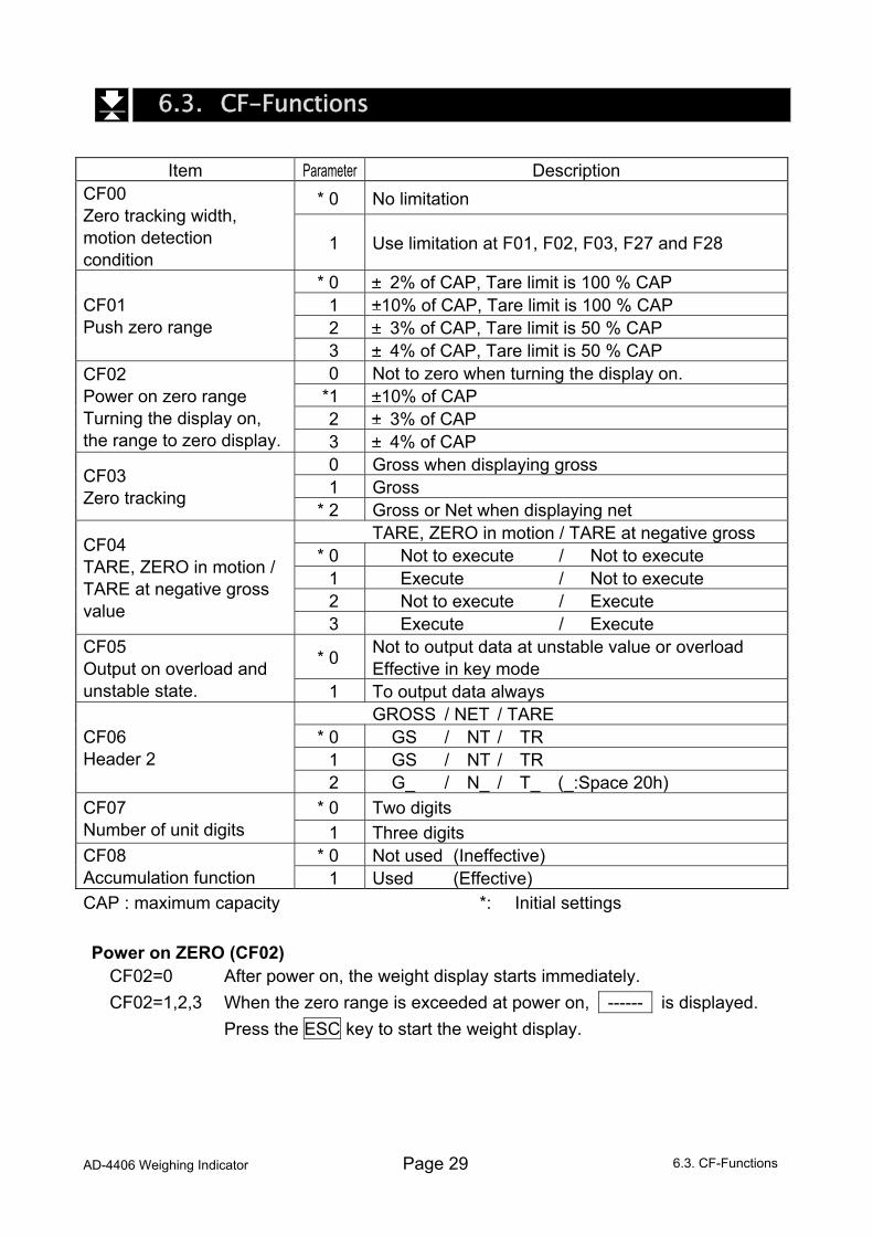
6.3. CF-Functions
Item Parameter Description * 0 No limitation CF00
Zero tracking width, motion detection condition
1 Use limitation at F01, F02, F03, F27 and F28
* 0 2% of CAP, Tare limit is 100 % CAP 1 10% of CAP, Tare limit is 100 % CAP 2 3% of CAP, Tare limit is 50 % CAP
CF01 Push zero range
3 4% of CAP, Tare limit is 50 % CAP 0 Not to zero when turning the display on.
*1 10% of CAP 2 3% of CAP
CF02 Power on zero range Turning the display on, the range to zero display. 3 4% of CAP
0 Gross when displaying gross 1 Gross CF03
Zero tracking * 2 Gross or Net when displaying net
TARE, ZERO in motion / TARE at negative gross * 0 Not to execute / Not to execute
1 Execute / Not to execute 2 Not to execute / Execute
CF04 TARE, ZERO in motion / TARE at negative gross value
3 Execute / Execute
* 0 Not to output data at unstable value or overload Effective in key mode
CF05 Output on overload and unstable state. 1 To output data always
GROSS / NET / TARE * 0 GS / NT / TR
1 GS / NT / TR CF06 Header 2
2 G_ / N_ / T_ (_:Space 20h) * 0 Two digits CF07
Number of unit digits 1 Three digits * 0 Not used (Ineffective) CF08
Accumulation function 1 Used (Effective) CAP : maximum capacity *: Initial settings Power on ZERO (CF02)
CF02=0 After power on, the weight display starts immediately. CF02=1,2,3 When the zero range is exceeded at power on, ------ is displayed. Press the ESC key to start the weight display.
6.3. CF-Functions
Page 30 AD-4406 Weighing Indicator
7. Function keys F1 and F2 For easier use, select functions of the F1 key and/or the F2 key and prioritize them in function settings. Functions that can be set are as follows:
“Print 1” or “Print 2” for serial data output in either format 1 or 2 “Add” for addition “totAL” for display of accumulated data "SEt Pt" for setting the code memory number and compared data “StArt” for starting comparison or batch weighing “StoP” for stopping comparison or forced termination of batch weighing "bU oFF" for stopping the sound of the comparison buzzer “Unit” for changing the unit “HoLd” for starting the average or releasing the hold data
The function set as first priority will operated when the F1 or F2 key is released and the functions of other priority, by pressing either the F1 or F2 key for more than 2 seconds. For further details, refer to each item’s description. Also, regardless of the function settings above, by pressing both the F1 and F2 keys or pressing one key while holding the other key, the following functions can be done. F1 + F2 Entering function settings F1 + NET/GROSS Displaying the accumulated data F2 + NET/GROSS Displaying and setting data number F2 + TARE Starting batch-weighing F2 + ON/OFF Changing the unit
7. Function keys F1 and F2
AD-4406 Weighing Indicator Page 31
8. Tare The function is used to display a net value with the container weight subtracted from
the total weight, if you place an object into a container to weigh it. Using the serial interface such as RS-232C, you can do this from the external equipment.
Caution When turning the power off, the tare data is cleared. (CF04=0,1) Weighing Tare
Operation Place the tare on the weighing unit. Press the TARE key to store the tare weight after the STABLE mark turns on. The display changes to net.
Caution When displaying a negative gross value, tare can not be used
(normally). To enable tare with a negative gross value, select a CF04 parameter.
Clearing Tare
When pressing the TARE key while gross is zero, tare is cleared and gross is displayed.
When zeroing with the ZERO key, tare is cleared.
8. Tare
Page 32 AD-4406 Weighing Indicator
9. Accumulation The function accumulates weight data and stores the total data and the
accumulation count. Data is stored in non-volatile memory, and is not lost even if power is turned off.
9.1. Preparation and Specification Set the following parameters to use the accumulation function. Select CF08 1 for the CF-function so that the accumulation function becomes effective. Specify the method of accumulation and data at F20 of the F-function. Specify the inhibit region for accumulation at F21 of the F-function. Selection of Accumulation Mode, F20 of the F-function
There are two methods of accumulation; manual accumulation using the key assigned to operate the M+ function and automatic accumulation.
The accumulated data can select "positive data only" or "both polarity data". The accumulated data can select "result of comparison is OK only" or "all result". Accumulation Condition, F21 of the F-function
In case of manual accumulation mode, press the key to accumulate weight data when the STABLE mark is displayed.
Data can be accumulated after the weight data enters the "inhibit region for output". When connecting the power cord and turning the display on, the accumulation mode takes the same action. Inhibit region for accumulation F21 Description
Add data anytime F21 0 Stable data can be used anytime.
Above 5 d F21 1 Initial setting Above 10 d F21 2 Above 20 d F21 3 Above 50 d F21 4
Caution Do not set F21=0 for the automatic accumulation mode. If setting F21=0, it may add the same data two times or more. Limitation of Accumulation Count and Total
The limitation of accumulation count is 999999. The limitation of total is 999999, ignoring the decimal point.
If exceeding these limitations, the data is not accumulated. Example: Setting the decimal point to "0.0", the limitation is "99999.9".
9. Accumulation
AD-4406 Weighing Indicator Page 33
9.2. Display and Operation Action of Accumulating Data
When accumulating data, the display blinks once. If the accumulated data is stored, the M+ mark is displayed. Caution This function can not accumulate data with a different unit. Specify a
unit before use. Display of Accumulated Data
When setting to CF08 1 (Effective accumulation function) and pressing the key that allows accumulation display, totAL is displayed and the total data is displayed with the M+ mark blinking. Pressing the TARE key alternatively displays the accumulated data and the accumulation count.
Pressing the ESC key, the weight data is displayed. The total data can be output. Refer to "Output of Accumulated Data".
Undoing the Accumulated Data
The last weight data can be deleted from the accumulated data unless new data has been accumulated.
Step 1 Press the key assigned to operate the function to display totAL and the accumulated data.
Step 2 Press and hold the +/- key for more than 3 seconds. The display blinks once and the data accumulated before accumulating the last weight data is displayed.
Caution External input can not be used. Clearing the Accumulated Data
Step 1 Press the key assigned to operate the function to display totAL and the accumulated data.
Step 2 Press and hold the ZERO key for more than 3 seconds. The display blinks once and the accumulated data is cleared.
Caution External input can not be used. Initializing the Data Number with Clearing the Accumulated Data
When the data number is included with the data of the serial data output, initializing the data number and clearing the accumulated data can be done at the same time.
Step 1 Press the key assigned to operate the function to display totAL and the accumulated data.
Step 2 Press and hold the ZERO and +/- keys at the same time for more than 3 seconds. The display blinks once and the accumulated data is cleared. And the data number is initialized (1).
Caution External input can not be used.
9. Accumulation
Page 34 AD-4406 Weighing Indicator
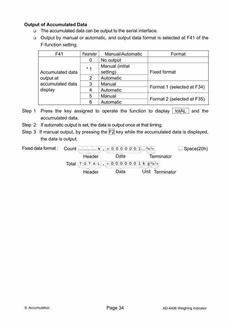
Output of Accumulated Data The accumulated data can be output to the serial interface. Output by manual or automatic, and output data format is selected at F41 of the
F-function setting.
F41 Parameter Manual/Automatic Format 0 No output
* 1 Manual (initial setting)
2 Automatic Fixed format
3 Manual 4 Automatic Format 1 (selected at F34)
5 Manual
Accumulated data output at accumulated data display
6 Automatic Format 2 (selected at F35)
Step 1 Press the key assigned to operate the function to display totAL and the accumulated data.
Step 2 If automatic output is set, the data is output once at that timing. Step 3 If manual output, by pressing the F2 key while the accumulated data is displayed,
the data is output.
Fixed data format :
9. Accumulation
AD-4406 Weighing Indicator Page 35
10. Code Memory The AD-4406 has four Code memories (1 through 4). Each Code memory stores a
set of setpoints. The data is stored in non-volatile memory, and is not lost even if power is turned off. Memory number 0 is a temporary memory and the data is lost when power is
turned off. The active code memory number can be changed by key switch, external control
input, or a command via the serial interface.
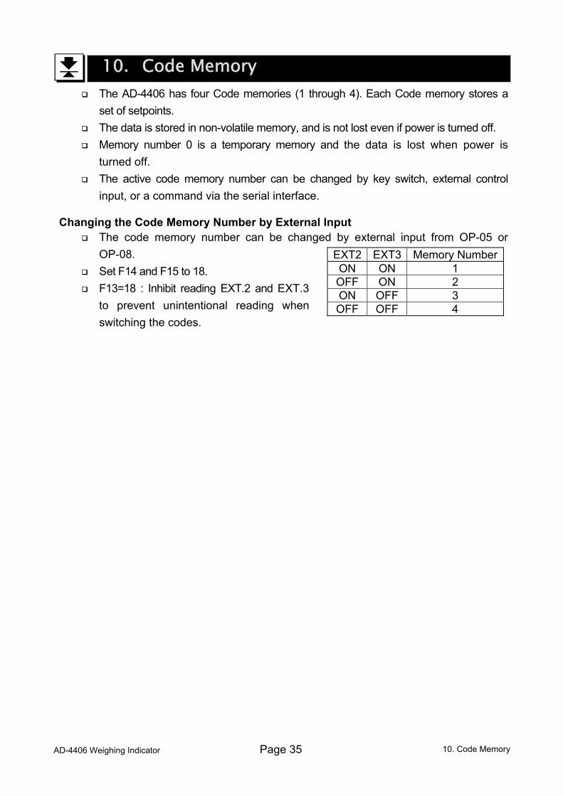
Changing the Code Memory Number by External Input The code memory number can be changed by external input from OP-05 or
OP-08. Set F14 and F15 to 18. F13=18 : Inhibit reading EXT.2 and EXT.3
to prevent unintentional reading when switching the codes.
EXT2 EXT3 Memory NumberON ON 1 OFF ON 2 ON OFF 3 OFF OFF 4
10. Code Memory
Page 36 AD-4406 Weighing Indicator
11. Comparison This function has the "upper / lower limit comparison", the "5-stage (HiHi/Hi/OK/Lo/LoLo)
comparison", the "setpoint comparison" and the "simple batch". They compare the weight data with preset parameters and can output the result of the comparison to the display and buzzer, also to the relay-outputs of OP-03, OP-05 and OP-08.
Set the F-function F22 and F23 to use the "upper / lower comparison", the "5-stage (HiHi/Hi/OK/Lo/LoLo) comparison" (these two comparison methods will be combined and hereafter be called the "Weight check mode"), and F22 through F26 to use the "setpoint comparison" and the "simple batch".
There are four code memories for the setpoints. Data is stored in non-volatile memory and is not lost even if power is turned off or the batteries are depleted.
Code memory can be selected by key switch, external control input, or a command via the serial interface.
11.1. Weight Check Mode This function compares the weight data with the upper and lower limit values
(upper/lower limit comparison) or with four limit values of HiHi, Hi, Lo and LoLo (5-stage comparison), and displays, sounds the buzzer and/or outputs the result to the three relays of HI, OK and LO. Use this comparison when judging whether a weight is proper.
Set the F-function F22 to 1, 2 or 3 to use the upper/ lower limit comparison and F22 to 4, 5 or 6 to use the 5-stage comparison.
Select a parameter of the F-function F23 for the comparison condition. Set the F-function F26 (zero band) if setting F23:10 (not compared in the zero band). Specify the upper and lower limit / HiHi, Hi, Lo, LoLo limit values. When entering the limit value(s), it is not necessary to enter the F-function F22 and
F23 again unless comparison conditions are changed. There are 3 type of setting values for each comparison.
(1) Set the limit value (upper and lower limit / HiHI, Hi, Lo, LoLo limit). (2) Set the Target value and an acceptable tolerance (upper and lower) in weight. The limit value is calculated automatically. (3) Set the Target value and an acceptable tolerance (upper and lower) in
percentage of the target weight. The limit value is calculated automatically. Example. Target = 50 kg, Upper limit = 51 kg, Lower limit = 48 kg
(1) Hi (Upper limit) : 51 (kg), Lo (Lower limit) : 48 (kg) (2) TG (Target) : 50 (kg), Hi (Upper acceptable tolerance) : 1 (kg), Lo (Lower acceptable tolerance) : 2 (kg) not a negative value (3) TG (Target) : 50 (kg), Hi (Upper acceptable tolerance) : 2 (% of Target),
Lo (Lower acceptable tolerance) : 4 (% of Target) not a negative value
11.1. Weight Check Mode
AD-4406 Weighing Indicator Page 37
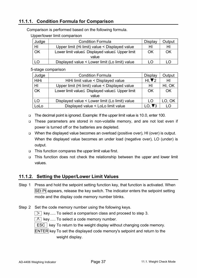
11.1.1. Condition Formula for Comparison
Comparison is performed based on the following formula. Upper/lower limit comparison
Judge Condition Formula Display Output HI Upper limit (Hi limit) value < Displayed value HI HI OK Lower limit value Displayed value Upper limit
value OK OK
LO Displayed value < Lower limit (Lo limit) value LO LO
5-stage comparison Judge Condition Formula Display Output HiHi HiHi limit value < Displayed value HI, 2 HI HI Upper limit (Hi limit) value < Displayed value HI HI, OK OK Lower limit value Displayed value Upper limit
value OK OK
LO Displayed value < Lower limit (Lo limit) value LO LO, OKLoLo Displayed value < LoLo limit value LO, 3 LO
The decimal point is ignored. Example: If the upper limit value is 10.0, enter 100. These parameters are stored in non-volatile memory, and are not lost even if
power is turned off or the batteries are depleted. When the displayed value becomes an overload (positive over), HI (over) is output.
When the displayed value becomes an under load (negative over), LO (under) is output.
This function compares the upper limit value first. This function does not check the relationship between the upper and lower limit
values.
11.1.2. Setting the Upper/Lower Limit Values
Step 1 Press and hold the setpoint setting function key, that function is activated. When SEt Pt appears, release the key switch. The indicator enters the setpoint setting mode and the display code memory number blinks.
Step 2 Set the code memory number using the following keys. key..... To select a comparison class and proceed to step 3. key ..... To select a code memory number. ESC key To return to the weight display without changing code memory. ENTER key To set the displayed code memory's setpoint and return to the
weight display. 11.1. Weight Check Mode
Page 38 AD-4406 Weighing Indicator
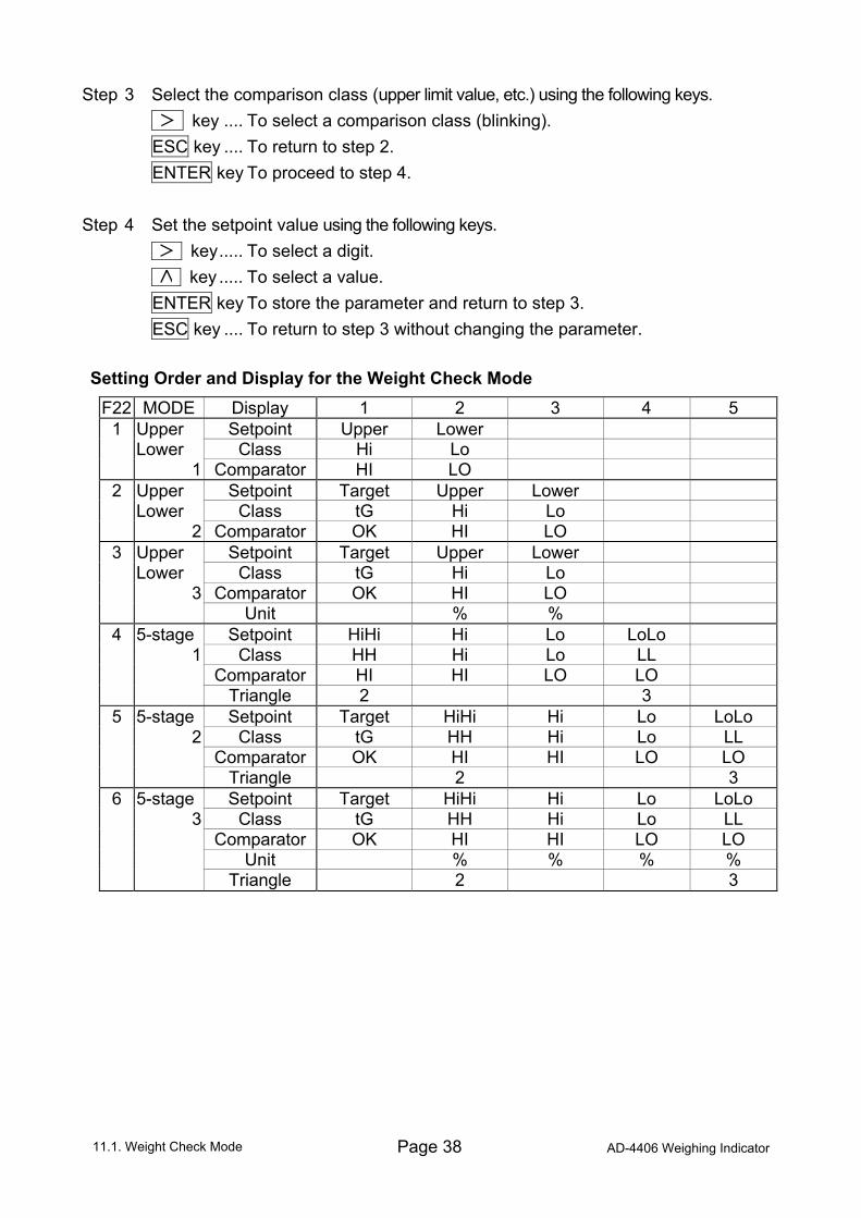
Step 3 Select the comparison class (upper limit value, etc.) using the following keys. key .... To select a comparison class (blinking). ESC key .... To return to step 2. ENTER key To proceed to step 4. Step 4 Set the setpoint value using the following keys. key..... To select a digit. key ..... To select a value. ENTER key To store the parameter and return to step 3. ESC key .... To return to step 3 without changing the parameter. Setting Order and Display for the Weight Check Mode
F22 MODE Display 1 2 3 4 5 1 Upper Setpoint Upper Lower Lower Class Hi Lo 1 Comparator HI LO
2 Upper Setpoint Target Upper Lower Lower Class tG Hi Lo 2 Comparator OK HI LO
3 Upper Setpoint Target Upper Lower Lower Class tG Hi Lo 3 Comparator OK HI LO Unit % %
4 5-stage Setpoint HiHi Hi Lo LoLo 1 Class HH Hi Lo LL Comparator HI HI LO LO Triangle 2 3
5 5-stage Setpoint Target HiHi Hi Lo LoLo 2 Class tG HH Hi Lo LL Comparator OK HI HI LO LO Triangle 2 3
6 5-stage Setpoint Target HiHi Hi Lo LoLo 3 Class tG HH Hi Lo LL Comparator OK HI HI LO LO Unit % % % % Triangle 2 3
11.1. Weight Check Mode
AD-4406 Weighing Indicator Page 39
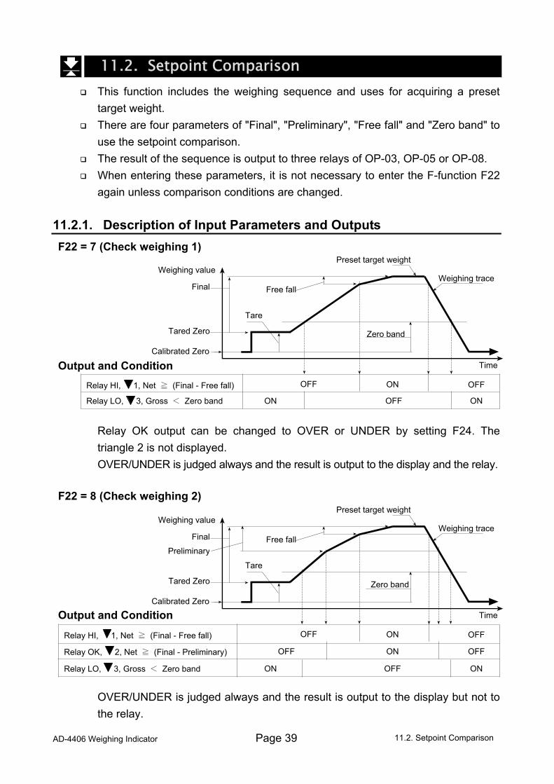
11.2. Setpoint Comparison This function includes the weighing sequence and uses for acquiring a preset
target weight. There are four parameters of "Final", "Preliminary", "Free fall" and "Zero band" to
use the setpoint comparison. The result of the sequence is output to three relays of OP-03, OP-05 or OP-08. When entering these parameters, it is not necessary to enter the F-function F22
again unless comparison conditions are changed. 11.2.1. Description of Input Parameters and Outputs F22 = 7 (Check weighing 1)
Output and Condition Relay OK output can be changed to OVER or UNDER by setting F24. The
triangle 2 is not displayed. OVER/UNDER is judged always and the result is output to the display and the relay. F22 = 8 (Check weighing 2)
Output and Condition OVER/UNDER is judged always and the result is output to the display but not to
the relay.
11.2. Setpoint Comparison
Final
Weighing value
Calibrated Zero
Tare
Tared Zero Zero band
Free fall
Preset target weight
Time
Weighing trace
Relay HI, 1, Net ≧ (Final - Free fall)
Relay LO, 3, Gross < Zero band ON
ON
ON
OFF
OFF
OFF
Final
Preliminary
Weighing value
Calibrated Zero
Tare
Tared Zero Zero band
Free fall
Preset target weight
Time
Weighing trace
Relay HI, 1, Net ≧ (Final - Free fall)
Relay OK, 2, Net ≧ (Final - Preliminary)
Relay LO, 3, Gross < Zero band ON
ON
ON
ON
OFF
OFF
OFF
OFF
OFF
Page 40 AD-4406 Weighing Indicator
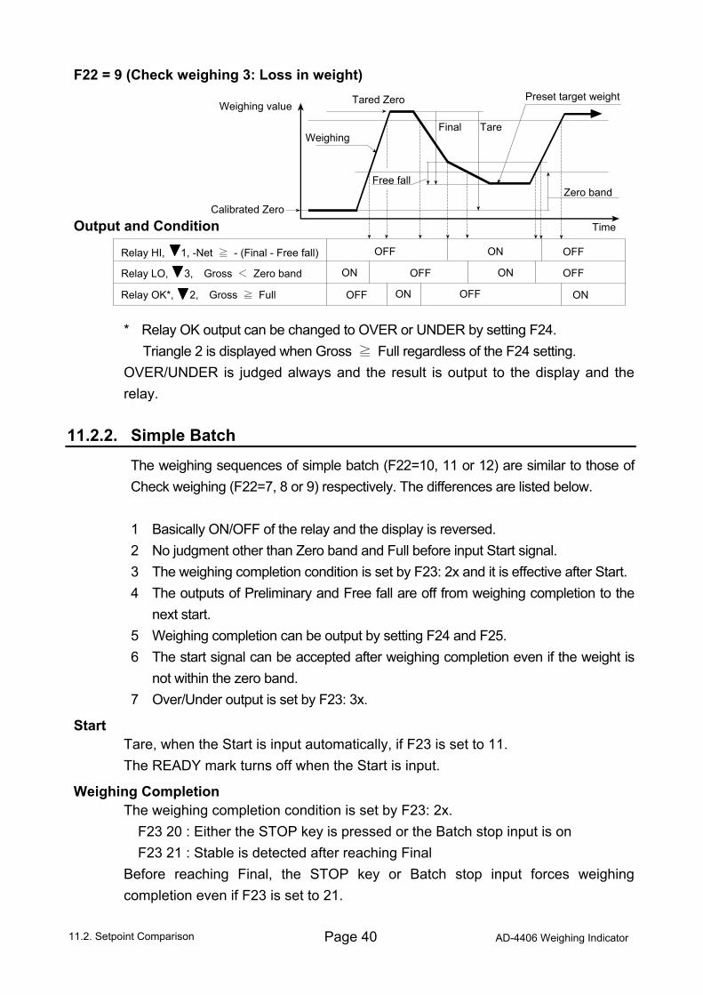
F22 = 9 (Check weighing 3: Loss in weight)
Output and Condition * Relay OK output can be changed to OVER or UNDER by setting F24. Triangle 2 is displayed when Gross ≧ Full regardless of the F24 setting. OVER/UNDER is judged always and the result is output to the display and the
relay. 11.2.2. Simple Batch
The weighing sequences of simple batch (F22=10, 11 or 12) are similar to those of Check weighing (F22=7, 8 or 9) respectively. The differences are listed below. 1 Basically ON/OFF of the relay and the display is reversed. 2 No judgment other than Zero band and Full before input Start signal. 3 The weighing completion condition is set by F23: 2x and it is effective after Start. 4 The outputs of Preliminary and Free fall are off from weighing completion to the
next start. 5 Weighing completion can be output by setting F24 and F25. 6 The start signal can be accepted after weighing completion even if the weight is
not within the zero band. 7 Over/Under output is set by F23: 3x.
Start Tare, when the Start is input automatically, if F23 is set to 11. The READY mark turns off when the Start is input.
Weighing Completion The weighing completion condition is set by F23: 2x. F23 20 : Either the STOP key is pressed or the Batch stop input is on F23 21 : Stable is detected after reaching Final Before reaching Final, the STOP key or Batch stop input forces weighing
completion even if F23 is set to 21.
11.2. Setpoint Comparison
Final
Weighing value
Calibrated Zero
Tare
Tared Zero
Zero bandFree fall
Preset target weight
Time
Weighing
Relay HI, 1, -Net ≧ - (Final - Free fall)
Relay OK*, 2, Gross ≧ Full
Relay LO, 3, Gross < Zero band ON
ON
ON ON
OFF
OFF
OFF
OFF
OFF
OFF
ON
AD-4406 Weighing Indicator Page 41
Toward the Zero band Preliminary and Free fall output are holding the off state. Over/Under comparison starts. If F23 is set to 30, judgment starts when Free fall turns
on. The judgment is not latched and the output is according to the state at the time. The Weighing completion relay is turned on if F24 is set to 2. The on time is set by F25. The READY mark is blinking regardless of the settings of F24 and F25. Start is may be accepted at this state.
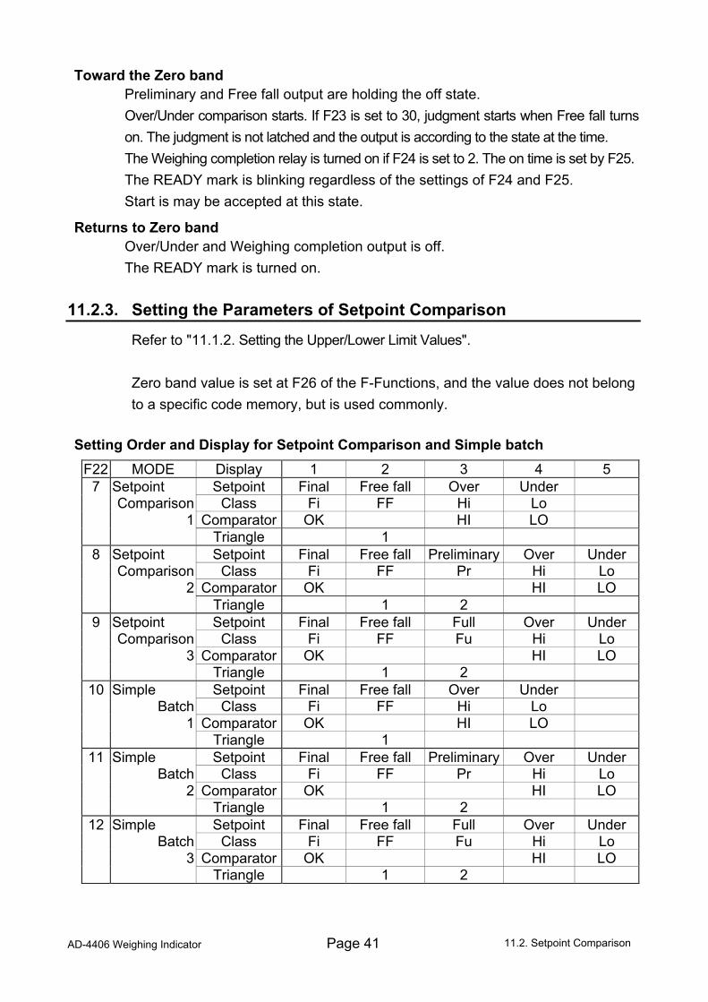
Returns to Zero band Over/Under and Weighing completion output is off. The READY mark is turned on. 11.2.3. Setting the Parameters of Setpoint Comparison
Refer to "11.1.2. Setting the Upper/Lower Limit Values". Zero band value is set at F26 of the F-Functions, and the value does not belong to a specific code memory, but is used commonly.
Setting Order and Display for Setpoint Comparison and Simple batch
F22 MODE Display 1 2 3 4 5 7 Setpoint Setpoint Final Free fall Over Under Comparison Class Fi FF Hi Lo 1 Comparator OK HI LO Triangle 1
8 Setpoint Setpoint Final Free fall Preliminary Over Under Comparison Class Fi FF Pr Hi Lo 2 Comparator OK HI LO Triangle 1 2
9 Setpoint Setpoint Final Free fall Full Over Under Comparison Class Fi FF Fu Hi Lo 3 Comparator OK HI LO Triangle 1 2
10 Simple Setpoint Final Free fall Over Under Batch Class Fi FF Hi Lo 1 Comparator OK HI LO Triangle 1
11 Simple Setpoint Final Free fall Preliminary Over Under Batch Class Fi FF Pr Hi Lo 2 Comparator OK HI LO Triangle 1 2
12 Simple Setpoint Final Free fall Full Over Under Batch Class Fi FF Fu Hi Lo 3 Comparator OK HI LO
Triangle 1 2
11.2. Setpoint Comparison
Page 42 AD-4406 Weighing Indicator
12. Hold Function This function displays the hold weight data after averaging the weight data for a
specific period. Useful to determine a live animal's weight. Averaging time is selectable up to 9.9 seconds by 0.1 second step. 3 methods are available to start averaging; manual start, automatic start after
stable, and manual / automatic start. Manual start is available with key switch or external input. Serial interface commands are also available; averaging start, releasing the hold
data and outputting the hold state. Refer to “13.3.4. Commands for Hold Function”. Caution This function can not be used under the setting CF00=1 Averaging can not start at a displayed value smaller than 0 +/- 5 digits. Data when the display is over is not included for averaging. When powered off, the hold is released automatically. There is no peak hold function. The display and the Data Output of Hold and Average
The weight display is blinking during the averaging period. The output data in the averaging period is the actual weight at the time. The weighing unit is blinking when the weight display is in the hold state. The output data format of the hold weight data is the same as that of the normal
weight data except the header of stable state is “HD” in the response to the “RW” or “RW,n” (n=1 or 2) command.
Relations to the Other Functions
If automatic accumulation (F20:21) and/or auto print (F37=2,3 F40=2,3) is set, accumulation and/or data output is performed after determining the hold data.
12.1. Setting the Hold Functions F27 determines the method of starting the average.
F27=1 Manual start: Starts the average and release with key switch operation. F27=2 Automatic start: After passing the inhibit region * and detect stable **,
starts the average automatically, releasing the data when the weight returns to inhibit region.
F27=3 Both Manual start and Automatic start. *inhibit region 0 +/- 5digits **stable detection Satisfied both F02 and F03
F28 determines the averaging time by 0.1second step. F28=0 holds the data at averaging start.
12. Hold Function
AD-4406 Weighing Indicator Page 43
The key switch will function as the HOLD key if F10 or F11 parameter is set to A. The external input function of averaging start is 19 and hold release is 20 of F13,
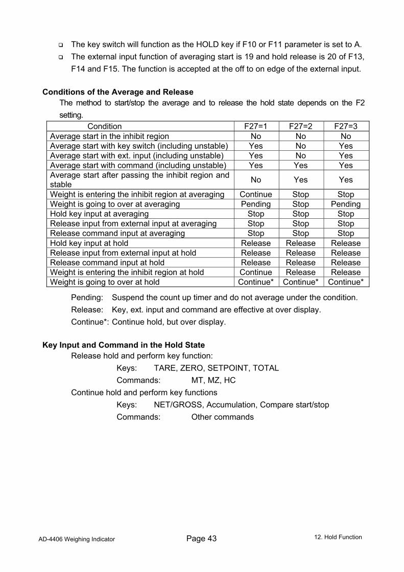
F14 and F15. The function is accepted at the off to on edge of the external input. Conditions of the Average and Release
The method to start/stop the average and to release the hold state depends on the F2 setting.
Condition F27=1 F27=2 F27=3 Average start in the inhibit region No No No Average start with key switch (including unstable) Yes No Yes Average start with ext. input (including unstable) Yes No Yes Average start with command (including unstable) Yes Yes Yes Average start after passing the inhibit region and stable No Yes Yes
Weight is entering the inhibit region at averaging Continue Stop Stop Weight is going to over at averaging Pending Stop Pending Hold key input at averaging Stop Stop Stop Release input from external input at averaging Stop Stop Stop Release command input at averaging Stop Stop Stop Hold key input at hold Release Release Release Release input from external input at hold Release Release Release Release command input at hold Release Release Release Weight is entering the inhibit region at hold Continue Release Release Weight is going to over at hold Continue* Continue* Continue*
Pending: Suspend the count up timer and do not average under the condition. Release: Key, ext. input and command are effective at over display. Continue*: Continue hold, but over display.
Key Input and Command in the Hold State
Release hold and perform key function: Keys: TARE, ZERO, SETPOINT, TOTAL Commands: MT, MZ, HC Continue hold and perform key functions Keys: NET/GROSS, Accumulation, Compare start/stop Commands: Other commands
12. Hold Function
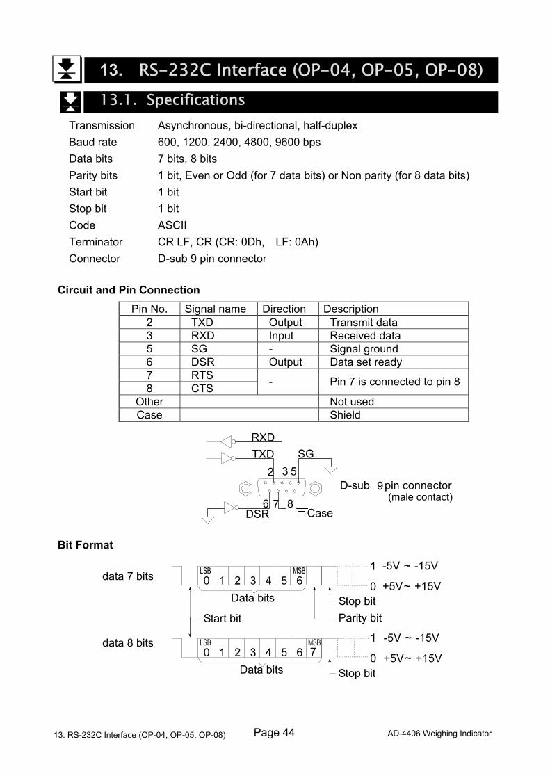
Page 44 AD-4406 Weighing Indicator
13. RS-232C Interface (OP-04, OP-05, OP-08) 13.1. Specifications
Transmission Asynchronous, bi-directional, half-duplex Baud rate 600, 1200, 2400, 4800, 9600 bps Data bits 7 bits, 8 bits Parity bits 1 bit, Even or Odd (for 7 data bits) or Non parity (for 8 data bits) Start bit 1 bit Stop bit 1 bit Code ASCII Terminator CR LF, CR (CR: 0Dh, LF: 0Ah) Connector D-sub 9 pin connector
Circuit and Pin Connection Pin No. Signal name Direction Description
2 TXD Output Transmit data 3 RXD Input Received data 5 SG - Signal ground 6 DSR Output Data set ready 7 RTS 8 CTS - Pin 7 is connected to pin 8
Other Not used Case Shield
Bit Format data 7 bits data 8 bits
13. RS-232C Interface (OP-04, OP-05, OP-08)
89
(male contact)
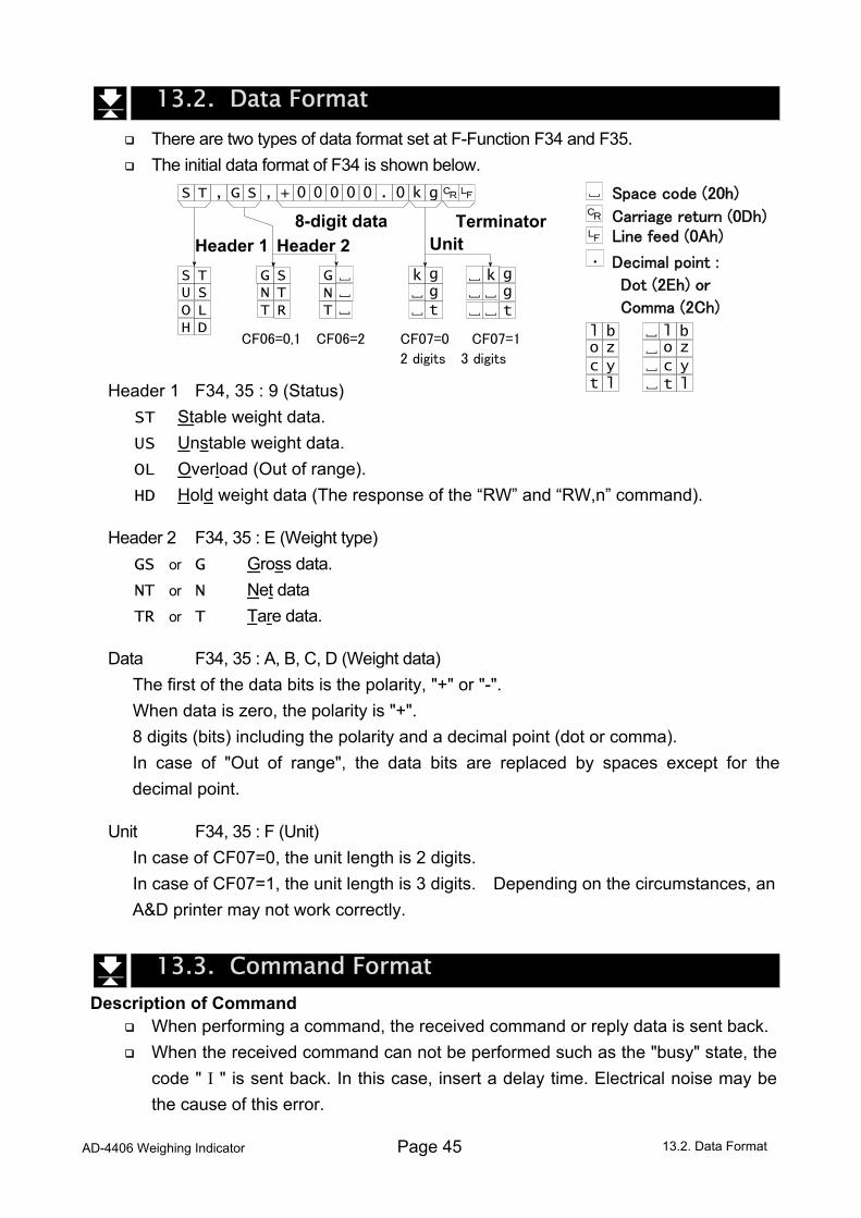
AD-4406 Weighing Indicator Page 45
13.2. Data Format There are two types of data format set at F-Function F34 and F35. The initial data format of F34 is shown below.
Header 1 F34, 35 : 9 (Status) ST Stable weight data. US Unstable weight data. OL Overload (Out of range). HD Hold weight data (The response of the “RW” and “RW,n” command).
Header 2 F34, 35 : E (Weight type) GS or G Gross data. NT or N Net data TR or T Tare data.
Data F34, 35 : A, B, C, D (Weight data) The first of the data bits is the polarity, "+" or "-". When data is zero, the polarity is "+". 8 digits (bits) including the polarity and a decimal point (dot or comma). In case of "Out of range", the data bits are replaced by spaces except for the
decimal point.
Unit F34, 35 : F (Unit) In case of CF07=0, the unit length is 2 digits. In case of CF07=1, the unit length is 3 digits. Depending on the circumstances, an
A&D printer may not work correctly.
13.3. Command Format Description of Command
When performing a command, the received command or reply data is sent back. When the received command can not be performed such as the "busy" state, the
code " I " is sent back. In this case, insert a delay time. Electrical noise may be the cause of this error.
13.2. Data Format
Carriage return (0Dh)
CF06=0,1 CF06=2 CF07=0 CF07=1
2 digits 3 digits
Header 1 Header 2 Unit8-digit data Terminator
T S , S G + , 0 0 0 0 0 0 . g k
T S S U L O D H
G N T
S G T N R T
g t
g k g
t
g k
l t
b l
l t
b l z o y c
z o y c
Space code (20h)
Line feed (0Ah)
Decimal point :
Dot (2Eh) or
Comma (2Ch)
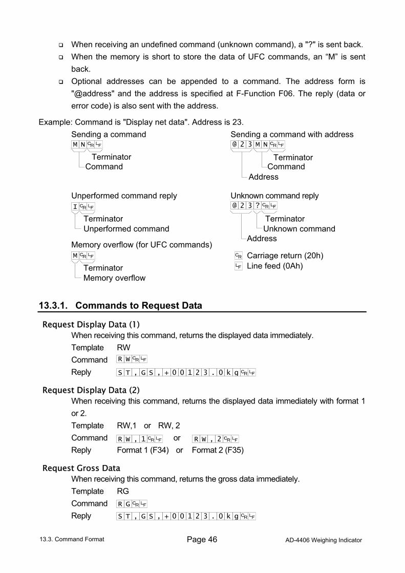
Page 46 AD-4406 Weighing Indicator
When receiving an undefined command (unknown command), a "?" is sent back. When the memory is short to store the data of UFC commands, an “M” is sent
back. Optional addresses can be appended to a command. The address form is
"@address" and the address is specified at F-Function F06. The reply (data or error code) is also sent with the address.
Example: Command is "Display net data". Address is 23. Sending a command Sending a command with address Unperformed command reply Unknown command reply Memory overflow (for UFC commands) 13.3.1. Commands to Request Data
Request Display Data (1) When receiving this command, returns the displayed data immediately. Template RW Command Reply
Request Display Data (2) When receiving this command, returns the displayed data immediately with format 1
or 2. Template RW,1 or RW, 2 Command or Reply Format 1 (F34) or Format 2 (F35)
Request Gross Data When receiving this command, returns the gross data immediately. Template RG Command Reply
13.3. Command Format
T S , S G + , 0 0 2 1 3 0 . g k
W R
W R 2 , W R 1 ,
T S , S G + , 0 0 2 1 3 0 . g k
G R
Carriage return (20h) Line feed (0Ah)
Address
Terminator Terminator
Terminator Terminator
Command Command
Unperformed command Unknown command
Address
TerminatorMemory overflow
M
I
M N M N @ 2 3
? @ 2 3
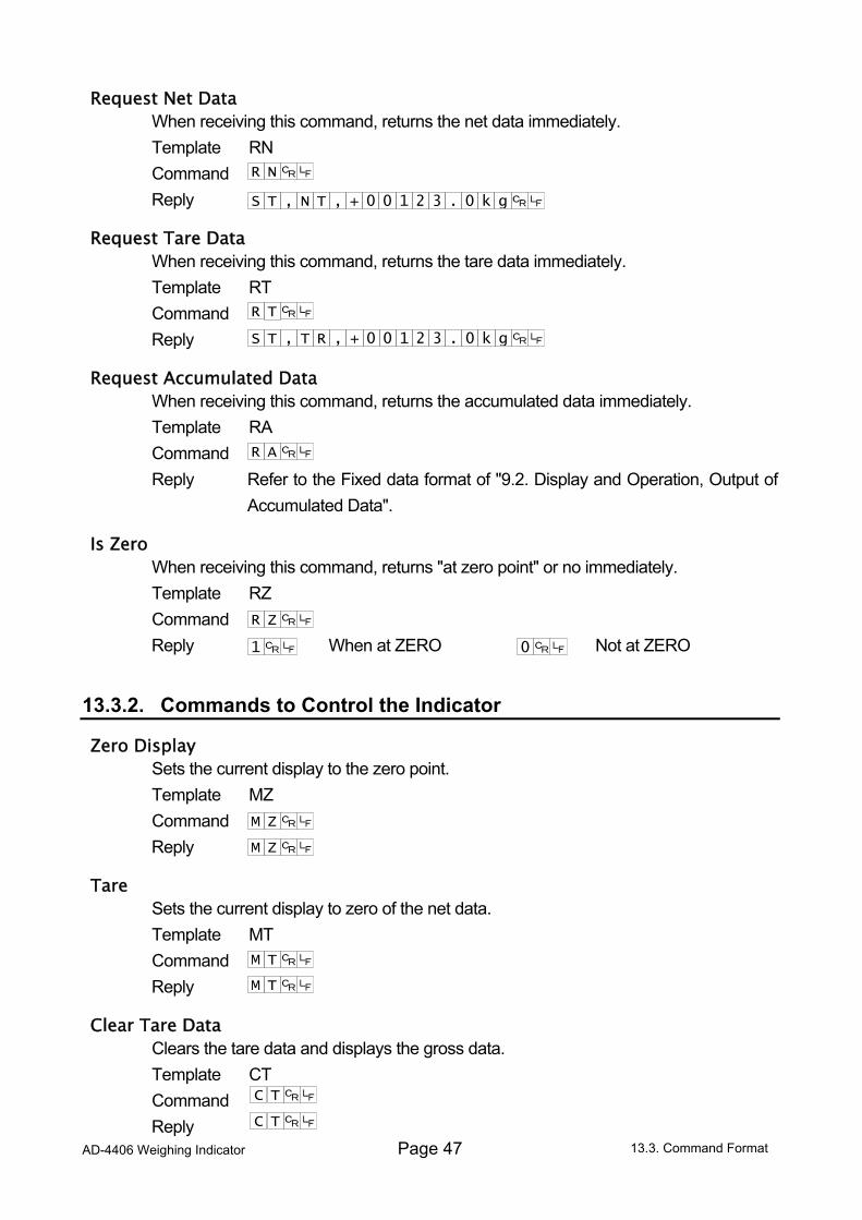
AD-4406 Weighing Indicator Page 47
Request Net Data When receiving this command, returns the net data immediately. Template RN Command Reply
Request Tare Data When receiving this command, returns the tare data immediately. Template RT Command Reply
Request Accumulated Data When receiving this command, returns the accumulated data immediately. Template RA Command Reply Refer to the Fixed data format of "9.2. Display and Operation, Output of
Accumulated Data".
Is Zero When receiving this command, returns "at zero point" or no immediately. Template RZ Command Reply When at ZERO Not at ZERO
13.3.2. Commands to Control the Indicator
Zero Display Sets the current display to the zero point. Template MZ Command Reply
Tare Sets the current display to zero of the net data. Template MT Command Reply
Clear Tare Data Clears the tare data and displays the gross data. Template CT Command Reply 13.3. Command Format
T S , T N + , 0 0 2 1 3 0 . g k
N R
A R
T R
T S , R T + , 0 0 2 1 3 0 . g k
1
Z R
0
Z M
Z M
T M
T M
T C
T C
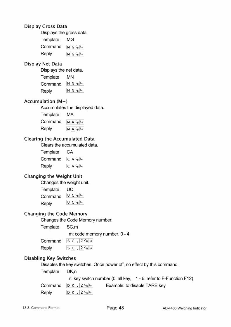
Page 48 AD-4406 Weighing Indicator
Display Gross Data Displays the gross data. Template MG Command Reply
Display Net Data Displays the net data. Template MN Command Reply
Accumulation (M+) Accumulates the displayed data. Template MA Command Reply
Clearing the Accumulated Data Clears the accumulated data. Template CA Command Reply
Changing the Weight Unit Changes the weight unit. Template UC Command Reply
Changing the Code Memory Changes the Code Memory number. Template SC,m m: code memory number, 0 - 4 Command Reply
Disabling Key Switches Disables the key switches. Once power off, no effect by this command. Template DK,n n: key switch number (0: all key, 1 - 6: refer to F-Function F12) Command Example: to disable TARE key Reply
13.3. Command Format
K D 2 ,
K D 2 ,
G M
G M
C S 2 ,
N M
N M
A M
A M
A C
A C
C U
C U
C S 2 ,
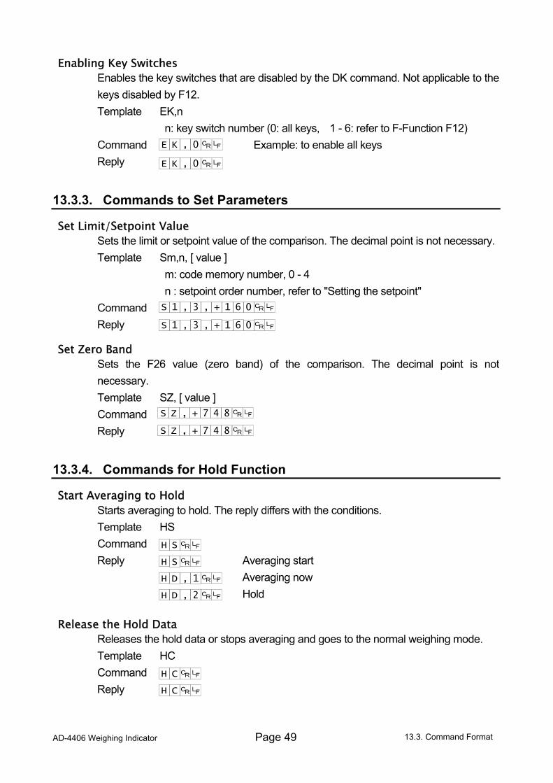
AD-4406 Weighing Indicator Page 49
Enabling Key Switches Enables the key switches that are disabled by the DK command. Not applicable to the
keys disabled by F12. Template EK,n n: key switch number (0: all keys, 1 - 6: refer to F-Function F12) Command Example: to enable all keys Reply
13.3.3. Commands to Set Parameters
Set Limit/Setpoint Value Sets the limit or setpoint value of the comparison. The decimal point is not necessary. Template Sm,n, [ value ] m: code memory number, 0 - 4 n : setpoint order number, refer to "Setting the setpoint" Command Reply
Set Zero Band Sets the F26 value (zero band) of the comparison. The decimal point is not
necessary. Template SZ, [ value ] Command Reply
13.3.4. Commands for Hold Function
Start Averaging to Hold Starts averaging to hold. The reply differs with the conditions. Template HS Command Reply Averaging start Averaging now Hold
Release the Hold Data Releases the hold data or stops averaging and goes to the normal weighing mode. Template HC Command Reply
13.3. Command Format
K E 0 ,
K E 0 ,
D H 1 ,
D H 2 ,
S H
S H
C H
C H
1 S , , 3 1 + 0 6
1 S , , 3 1 + 0 6
Z S , 7 + 8 4
Z S , 7 + 8 4
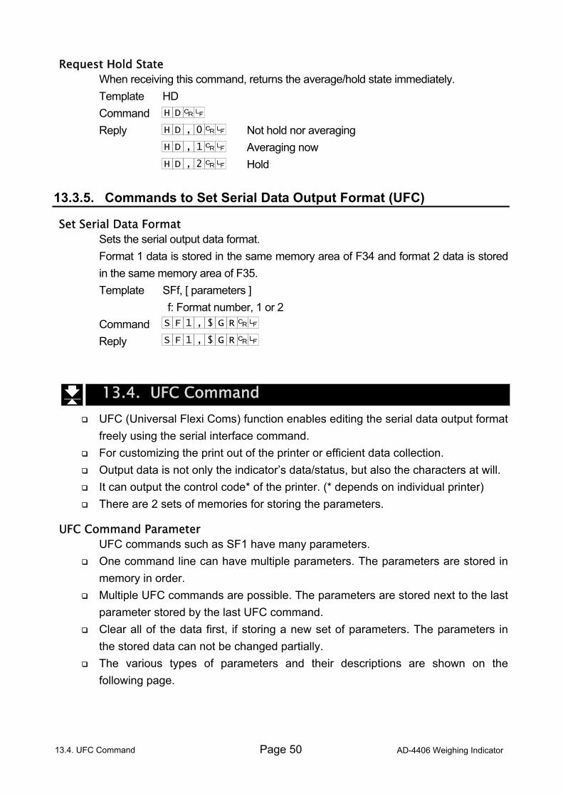
Page 50 AD-4406 Weighing Indicator
Request Hold State When receiving this command, returns the average/hold state immediately. Template HD Command Reply Not hold nor averaging Averaging now Hold 13.3.5. Commands to Set Serial Data Output Format (UFC)
Set Serial Data Format Sets the serial output data format. Format 1 data is stored in the same memory area of F34 and format 2 data is stored
in the same memory area of F35. Template SFf, [ parameters ] f: Format number, 1 or 2 Command Reply
13.4. UFC Command UFC (Universal Flexi Coms) function enables editing the serial data output format
freely using the serial interface command. For customizing the print out of the printer or efficient data collection. Output data is not only the indicator’s data/status, but also the characters at will. It can output the control code* of the printer. (* depends on individual printer) There are 2 sets of memories for storing the parameters.
UFC Command Parameter UFC commands such as SF1 have many parameters. One command line can have multiple parameters. The parameters are stored in
memory in order. Multiple UFC commands are possible. The parameters are stored next to the last
parameter stored by the last UFC command. Clear all of the data first, if storing a new set of parameters. The parameters in
the stored data can not be changed partially. The various types of parameters and their descriptions are shown on the
following page.
13.4. UFC Command
D H 0 ,
D H 1 ,
D H 2 ,
D H
F S 1 $ , R G
F S 1 $ , R G
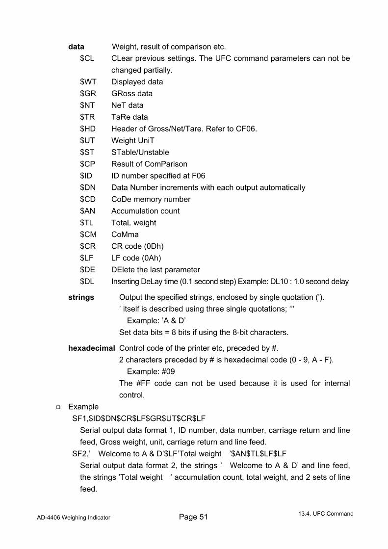
AD-4406 Weighing Indicator Page 51
data Weight, result of comparison etc. $CL CLear previous settings. The UFC command parameters can not be
changed partially. $WT Displayed data $GR GRoss data $NT NeT data $TR TaRe data $HD Header of Gross/Net/Tare. Refer to CF06. $UT Weight UniT $ST STable/Unstable $CP Result of ComParison $ID ID number specified at F06 $DN Data Number increments with each output automatically $CD CoDe memory number $AN Accumulation count $TL TotaL weight $CM CoMma $CR CR code (0Dh) $LF LF code (0Ah) $DE DElete the last parameter $DL Inserting DeLay time (0.1 second step) Example: DL10 : 1.0 second delay
strings Output the specified strings, enclosed by single quotation (’). ’ itself is described using three single quotations; ’’’ Example: ’A & D’ Set data bits = 8 bits if using the 8-bit characters.
hexadecimal Control code of the printer etc, preceded by #. 2 characters preceded by # is hexadecimal code (0 - 9, A - F). Example: #09
The #FF code can not be used because it is used for internal control.
Example SF1,$ID$DN$CR$LF$GR$UT$CR$LF
Serial output data format 1, ID number, data number, carriage return and line feed, Gross weight, unit, carriage return and line feed.
SF2,’ Welcome to A & D’$LF’Total weight ’$AN$TL$LF$LF Serial output data format 2, the strings ’ Welcome to A & D’ and line feed, the strings ’Total weight ’ accumulation count, total weight, and 2 sets of line feed.
13.4. UFC Command
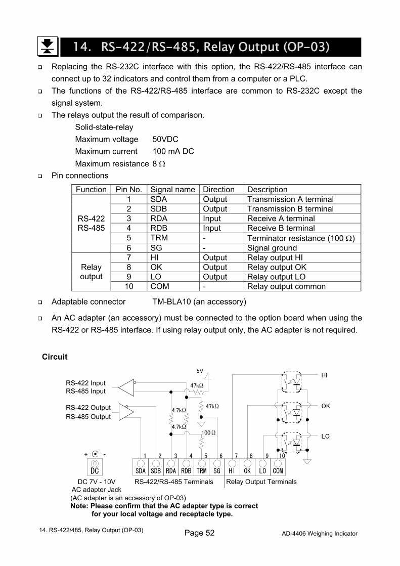
Page 52 AD-4406 Weighing Indicator
14. RS-422/RS-485, Relay Output (OP-03) Replacing the RS-232C interface with this option, the RS-422/RS-485 interface can
connect up to 32 indicators and control them from a computer or a PLC. The functions of the RS-422/RS-485 interface are common to RS-232C except the
signal system. The relays output the result of comparison.
Solid-state-relay Maximum voltage 50VDC Maximum current 100 mA DC Maximum resistance 8 Ω
Pin connections
Function Pin No. Signal name Direction Description 1 SDA Output Transmission A terminal 2 SDB Output Transmission B terminal 3 RDA Input Receive A terminal 4 RDB Input Receive B terminal 5 TRM - Terminator resistance (100 Ω)
RS-422 RS-485
6 SG - Signal ground 7 HI Output Relay output HI 8 OK Output Relay output OK 9 LO Output Relay output LO
Relay output
10 COM - Relay output common
Adaptable connector TM-BLA10 (an accessory)
An AC adapter (an accessory) must be connected to the option board when using the RS-422 or RS-485 interface. If using relay output only, the AC adapter is not required.
Circuit
14. RS-422/485, Relay Output (OP-03)
HI OK LO COM
HI
OK
LO
Relay Output Terminals
RS-422 Output RS-485 Output
RS-422 Input RS-485 Input
7 8 9
SDA SDB RDA RDB TRM
5V
47kΩ
4.7kΩ
47kΩ
4.7kΩ
100Ω
RS-422/RS-485 Terminals
1 2 3 4 5 6
SG
10
DC
DC 7V - 10V AC adapter Jack(AC adapter is an accessory of OP-03) Note: Please confirm that the AC adapter type is correct
for your local voltage and receptacle type.
+ -
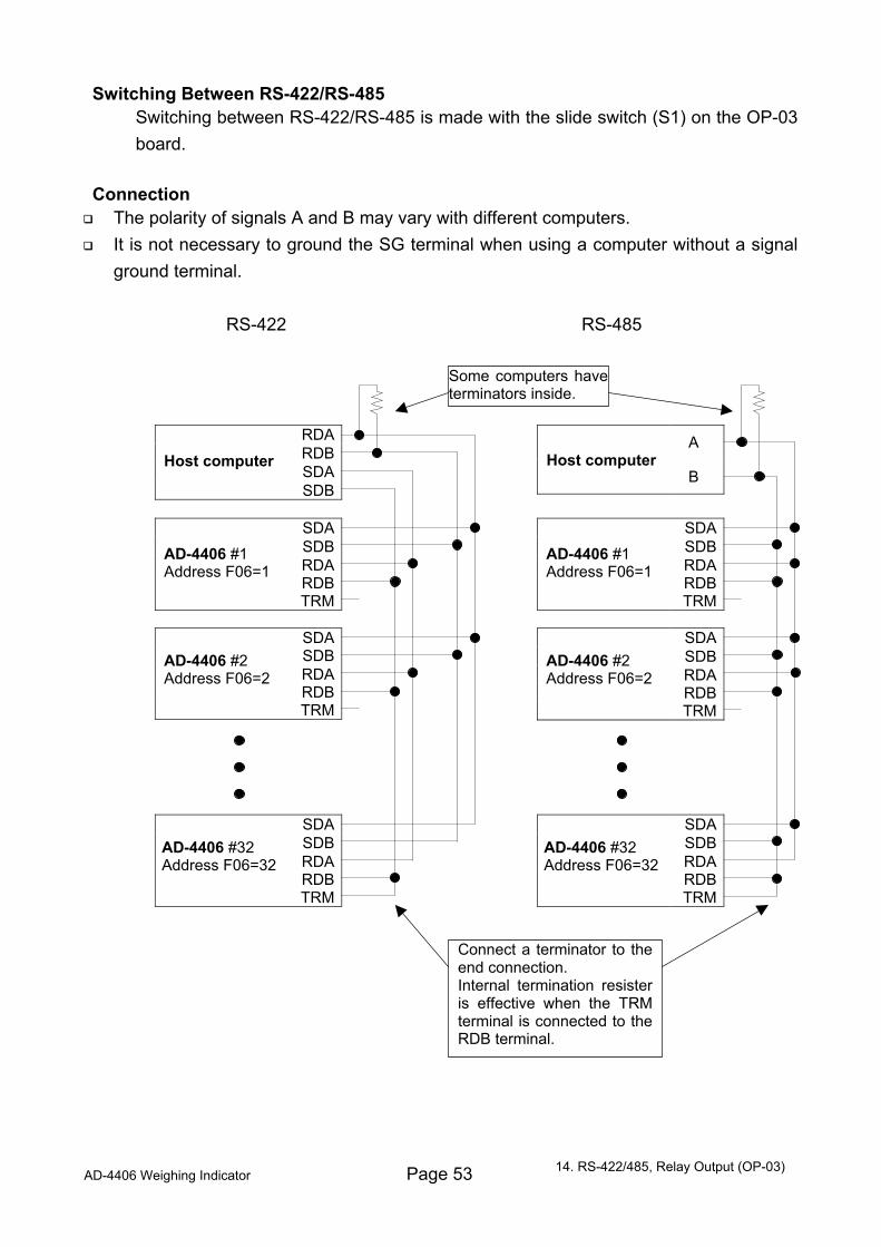
AD-4406 Weighing Indicator Page 53
Switching Between RS-422/RS-485 Switching between RS-422/RS-485 is made with the slide switch (S1) on the OP-03
board.
Connection The polarity of signals A and B may vary with different computers. It is not necessary to ground the SG terminal when using a computer without a signal
ground terminal.
RS-422 RS-485
14. RS-422/485, Relay Output (OP-03)
RDA RDB SDA
SDB
SDA SDB RDA RDB
TRM
SDA SDB RDA RDB
TRM
SDA SDB RDA RDB
TRM
SDA SDB RDA RDB
TRM
SDA SDB RDA RDB
TRM
A
B
Some computers haveterminators inside.
SDA SDB RDA RDB
TRM
AD-4406 #32 Address F06=32
AD-4406 #32 Address F06=32
AD-4406 #2 Address F06=2
AD-4406 #2 Address F06=2
AD-4406 #1 Address F06=1
AD-4406 #1 Address F06=1
Host computer Host computer
Connect a terminator to the end connection. Internal termination resister is effective when the TRM terminal is connected to the RDB terminal.
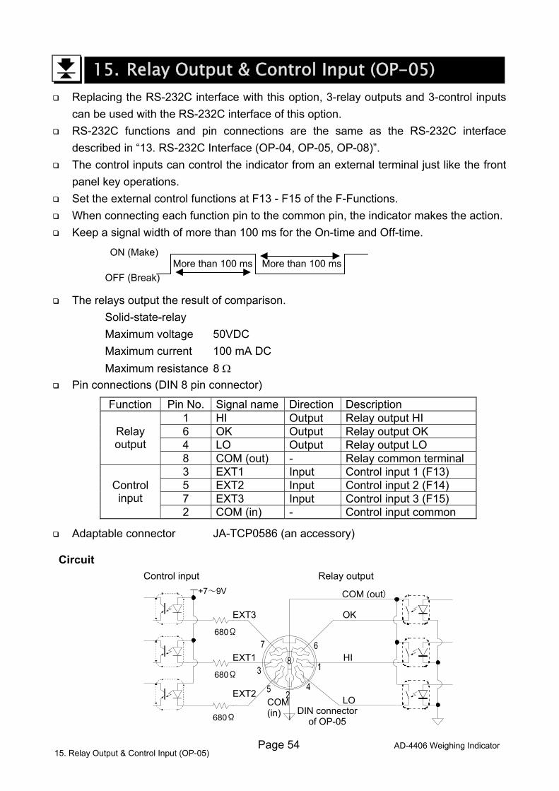
Page 54 AD-4406 Weighing Indicator
15. Relay Output & Control Input (OP-05) Replacing the RS-232C interface with this option, 3-relay outputs and 3-control inputs
can be used with the RS-232C interface of this option. RS-232C functions and pin connections are the same as the RS-232C interface
described in “13. RS-232C Interface (OP-04, OP-05, OP-08)”. The control inputs can control the indicator from an external terminal just like the front
panel key operations. Set the external control functions at F13 - F15 of the F-Functions. When connecting each function pin to the common pin, the indicator makes the action. Keep a signal width of more than 100 ms for the On-time and Off-time.
ON (Make) More than 100 ms More than 100 ms
OFF (Break)
The relays output the result of comparison. Solid-state-relay Maximum voltage 50VDC Maximum current 100 mA DC Maximum resistance 8 Ω
Pin connections (DIN 8 pin connector)
Function Pin No. Signal name Direction Description 1 HI Output Relay output HI 6 OK Output Relay output OK 4 LO Output Relay output LO
Relay output
8 COM (out) - Relay common terminal 3 EXT1 Input Control input 1 (F13) 5 EXT2 Input Control input 2 (F14) 7 EXT3 Input Control input 3 (F15)
Control input
2 COM (in) - Control input common
Adaptable connector JA-TCP0586 (an accessory)
Circuit
HI
OK
LO
COM (out)
i
EXT3
EXT2
EXT1
+7~9V
680Ω
680Ω
680Ω
COM(in) DIN connector
of OP-05
Control input Relay output
15. Relay Output & Control Input (OP-05)
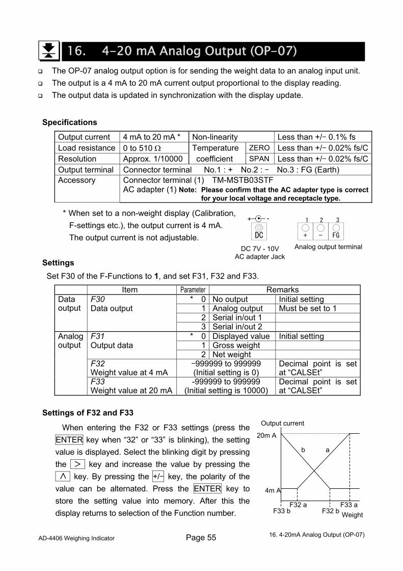
AD-4406 Weighing Indicator Page 55
16. 4-20 mA Analog Output (OP-07) The OP-07 analog output option is for sending the weight data to an analog input unit. The output is a 4 mA to 20 mA current output proportional to the display reading. The output data is updated in synchronization with the display update.
Specifications
Output current 4 mA to 20 mA * Non-linearity Less than +/- 0.1% fs Load resistance 0 to 510 Ω Temperature ZERO Less than +/- 0.02% fs/CResolution Approx. 1/10000 coefficient SPAN Less than +/- 0.02% fs/COutput terminal Connector terminal No.1 : + No.2 : - No.3 : FG (Earth) Accessory Connector terminal (1) TM-MSTB03STF
AC adapter (1) Note: Please confirm that the AC adapter type is correct for your local voltage and receptacle type.
* When set to a non-weight display (Calibration, F-settings etc.), the output current is 4 mA.
The output current is not adjustable.
Settings Set F30 of the F-Functions to 1, and set F31, F32 and F33.
Item Parameter Remarks F30 * 0 No output Initial setting Data output 1 Analog output Must be set to 1 2 Serial in/out 1
Data output
3 Serial in/out 2 F31 * 0 Displayed value Initial setting Output data 1 Gross weight 2 Net weight F32 Weight value at 4 mA
-999999 to 999999 (Initial setting is 0)
Decimal point is set at “CALSEt”
Analog output
F33 Weight value at 20 mA
-999999 to 999999 (Initial setting is 10000)
Decimal point is set at “CALSEt”
Settings of F32 and F33
When entering the F32 or F33 settings (press the ENTER key when “32” or “33” is blinking), the setting value is displayed. Select the blinking digit by pressing the key and increase the value by pressing the 1 key. By pressing the +/- key, the polarity of the value can be alternated. Press the ENTER key to store the setting value into memory. After this the display returns to selection of the Function number.
Analog output terminal+ - FG
1 2 3
DC
DC 7V - 10V AC adapter Jack
+ -
16. 4-20mA Analog Output (OP-07)
Output current
Weight
20m A
4m A
F32 a F33 aF32 bF33 b
a b
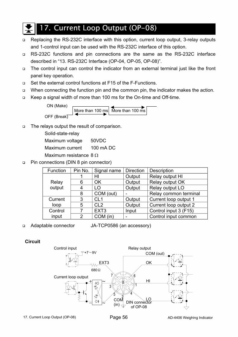
Page 56 AD-4406 Weighing Indicator
17. Current Loop Output (OP-08) Replacing the RS-232C interface with this option, current loop output, 3-relay outputs
and 1-control input can be used with the RS-232C interface of this option. RS-232C functions and pin connections are the same as the RS-232C interface
described in “13. RS-232C Interface (OP-04, OP-05, OP-08)”. The control input can control the indicator from an external terminal just like the front
panel key operation. Set the external control functions at F15 of the F-Functions. When connecting the function pin and the common pin, the indicator makes the action. Keep a signal width of more than 100 ms for the On-time and Off-time.
ON (Make) More than 100 ms More than 100 ms
OFF (Break)
The relays output the result of comparison. Solid-state-relay Maximum voltage 50VDC Maximum current 100 mA DC Maximum resistance 8 Ω
Pin connections (DIN 8 pin connector)
Function Pin No. Signal name Direction Description 1 HI Output Relay output HI 6 OK Output Relay output OK 4 LO Output Relay output LO
Relay output
8 COM (out) - Relay common terminal 3 CL1 Output Current loop output 1 Current
loop 5 CL2 Output Current loop output 2 7 EXT3 Input Control input 3 (F15) Control
input 2 COM (in) - Control input common
Adaptable connector JA-TCP0586 (an accessory)
Circuit
Current loop output HI
OK
LO
COM (out)
i
EXT3
~
+7~9V
680Ω
+
COM(in)
~
- DIN connector of OP-08
Control input Relay output
17. Current Loop Output (OP-08)
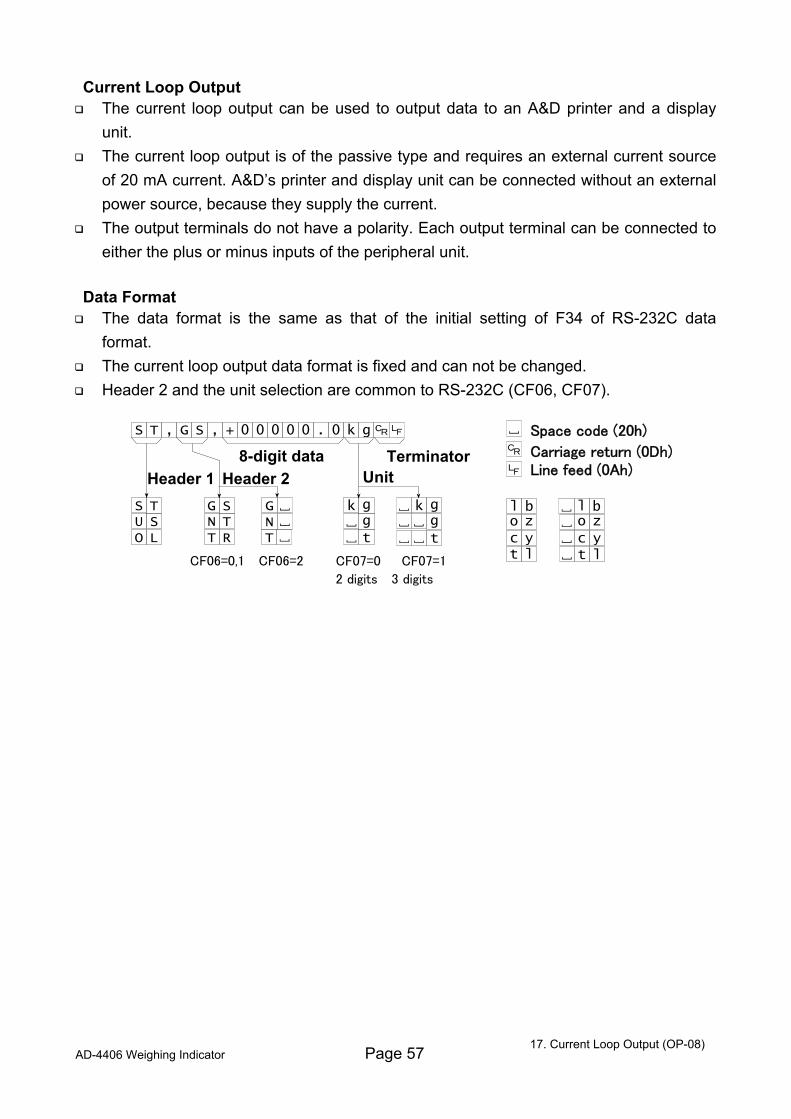
AD-4406 Weighing Indicator Page 57
Current Loop Output The current loop output can be used to output data to an A&D printer and a display
unit. The current loop output is of the passive type and requires an external current source
of 20 mA current. A&D’s printer and display unit can be connected without an external power source, because they supply the current.
The output terminals do not have a polarity. Each output terminal can be connected to either the plus or minus inputs of the peripheral unit.
Data Format The data format is the same as that of the initial setting of F34 of RS-232C data
format. The current loop output data format is fixed and can not be changed. Header 2 and the unit selection are common to RS-232C (CF06, CF07).
17. Current Loop Output (OP-08)
Carriage return (0Dh)
CF06=0,1 CF06=2 CF07=0 CF07=1
2 digits 3 digits
Header 1 Header 2 Unit8-digit data Terminator
T S , S G + , 0 0 0 0 0 0 . g k
T S S U L O
G N T
S G T N R T
g t
g k g
t
g k
l t
b l
l t
b l z o y c
z o y c
Space code (20h)
Line feed (0Ah)
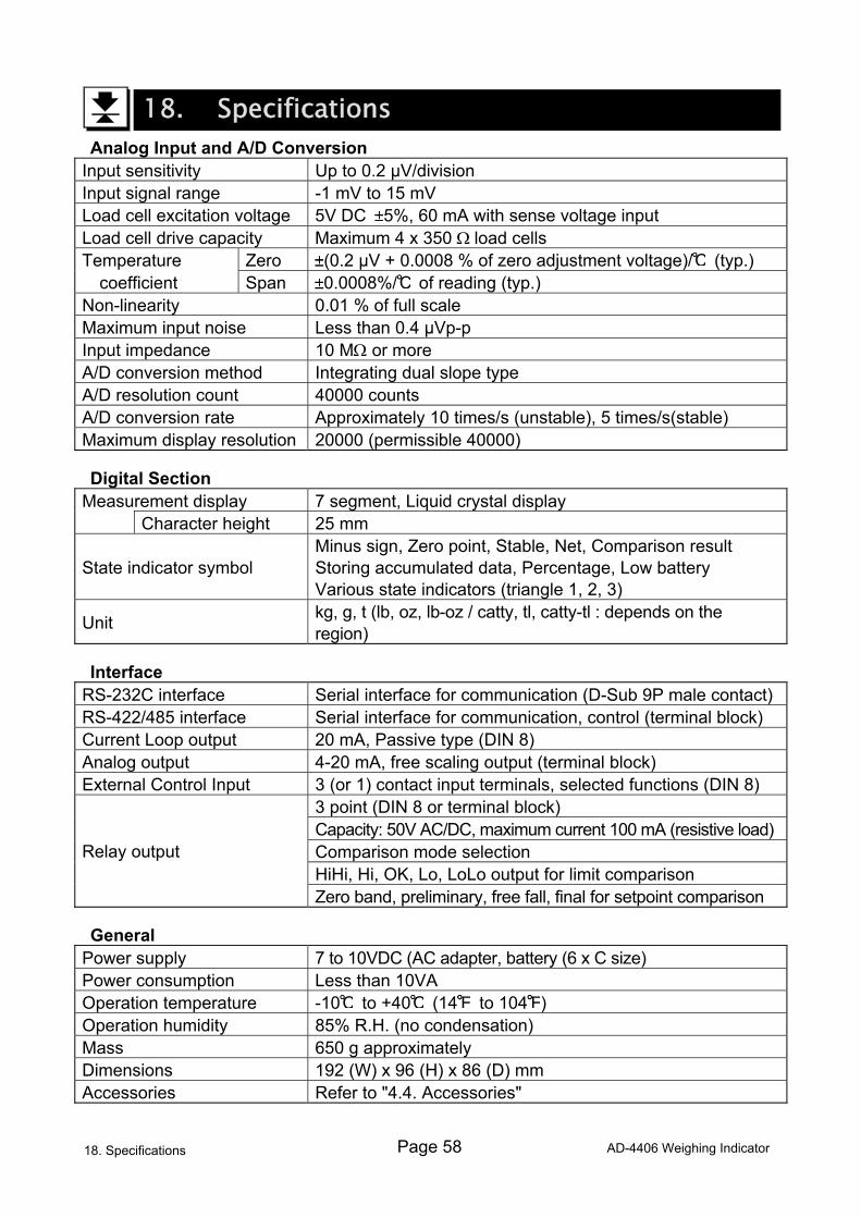
Page 58 AD-4406 Weighing Indicator
18. Specifications Analog Input and A/D Conversion
Input sensitivity Up to 0.2 µV/division Input signal range -1 mV to 15 mV Load cell excitation voltage 5V DC 5%, 60 mA with sense voltage input Load cell drive capacity Maximum 4 x 350 Ω load cells Temperature Zero (0.2 µV + 0.0008 % of zero adjustment voltage)/ (typ.) coefficient Span 0.0008%/ of reading (typ.) Non-linearity 0.01 % of full scale Maximum input noise Less than 0.4 µVp-p Input impedance 10 MΩ or more A/D conversion method Integrating dual slope type A/D resolution count 40000 counts A/D conversion rate Approximately 10 times/s (unstable), 5 times/s(stable) Maximum display resolution 20000 (permissible 40000)
Digital Section Measurement display 7 segment, Liquid crystal display Character height 25 mm
State indicator symbol Minus sign, Zero point, Stable, Net, Comparison result Storing accumulated data, Percentage, Low battery Various state indicators (triangle 1, 2, 3)
Unit kg, g, t (lb, oz, lb-oz / catty, tl, catty-tl : depends on the region)
Interface RS-232C interface Serial interface for communication (D-Sub 9P male contact) RS-422/485 interface Serial interface for communication, control (terminal block) Current Loop output 20 mA, Passive type (DIN 8) Analog output 4-20 mA, free scaling output (terminal block) External Control Input 3 (or 1) contact input terminals, selected functions (DIN 8)
3 point (DIN 8 or terminal block) Capacity: 50V AC/DC, maximum current 100 mA (resistive load)Comparison mode selection HiHi, Hi, OK, Lo, LoLo output for limit comparison
Relay output
Zero band, preliminary, free fall, final for setpoint comparison
General Power supply 7 to 10VDC (AC adapter, battery (6 x C size) Power consumption Less than 10VA Operation temperature -10 to +40 (14 to 104 ) Operation humidity 85% R.H. (no condensation) Mass 650 g approximately Dimensions 192 (W) x 96 (H) x 86 (D) mm Accessories Refer to "4.4. Accessories"
18. Specifications
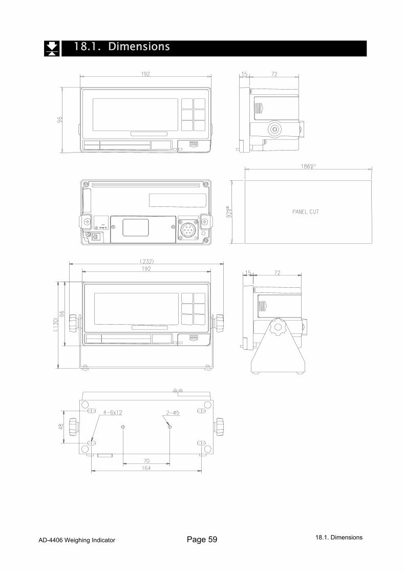
AD-4406 Weighing Indicator Page 59
18.1. Dimensions
18.1. Dimensions