Embed Size (px)
Citation preview
ADAM-4022T Serial Base Dual Loops
PID Controller User’s Manual

- 1 -
Warning Message : The ADAM-4022T is recommended to be used in general purposed air conditioning application. When using this product in applications that required particular safety or when using this product in important facility, pay attention to the safety of the overall system and equipment. For example, install fail-safe mechanism, carry out redundancy checks and periodic inspections, and adopt other appropriate safety measures as required.
- 2 -
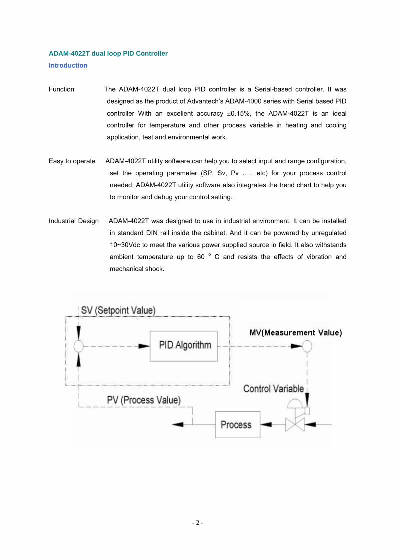
ADAM-4022T dual loop PID Controller
Introduction
Function The ADAM-4022T dual loop PID controller is a Serial-based controller. It was
designed as the product of Advantech’s ADAM-4000 series with Serial based PID
controller With an excellent accuracy ±0.15%, the ADAM-4022T is an ideal
controller for temperature and other process variable in heating and cooling
application, test and environmental work.
Easy to operate ADAM-4022T utility software can help you to select input and range configuration,
set the operating parameter (SP, Sv, Pv ….. etc) for your process control
needed. ADAM-4022T utility software also integrates the trend chart to help you
to monitor and debug your control setting.
Industrial Design ADAM-4022T was designed to use in industrial environment. It can be installed
in standard DIN rail inside the cabinet. And it can be powered by unregulated
10~30Vdc to meet the various power supplied source in field. It also withstands
ambient temperature up to 60 o C and resists the effects of vibration and
mechanical shock.
- 3 -
Specification of IO channels
Analog Input: 4 Channel Differential Input
Effective resolution: 16-bit
Individual wire burn-out detect
Input type: 0~10V, 0~20mA, 4~20mA, Thermistor, RTD
Isolation Voltage: 2000 VDC
Sampling rate: 10 samples/second
Thermistor Type and Temperature Ranges
Thermistor 3K 0oC to 100oC
Thermistor 10K 0oC to 100oC
RTD Type and Temperature Ranges
Pt 100 RTD
Pt -100oC to 100 oC
Pt 0 oC to 100 oC
Pt 0 oC to 200 oC
Pt 0 oC to 600 oC
IEC RTD 100 ohms (α = 0.00385)
JIS RTD 100 ohms (α = 0.00392)
Pt 1000 RTD
Pt -40oC to 160 oC
Accuracy: ± 0.15% or better
Zero drift: ± 6 µV/ oC
Span drift: ± 25 ppm/ oC
CMR @ 50/60 Hz: 92 dB
Analog Output: 2 Channels
Effective resolution: 12-bit
Output range: 0~10V, 0~20mA, 4~20mA
Accuracy: ± 0.05% of FSR
Isolation Voltage: 2000 VDC
Digital Input: 2 Channels
Logic level of Dry Contact: 0 close to GND
1 open Digital Output: 2 Channels
Open Collector to 30VDC, 100mA/max. load
- 4 -
Surge Protection (Power): 3000 VDC
Built-in Watchdog Timer
Power requirements: Unregulated +10 ~ +30 VDC
Power consumption: 4W @24 VDC
Environment:
Operating temperature: -10o ~ 70 o C
EMI: Meets CE and FCC Class A
Storage temperature: -25o ~ 85 o C
Humidity: 5% ~ 95% non-condensing
- 5 -
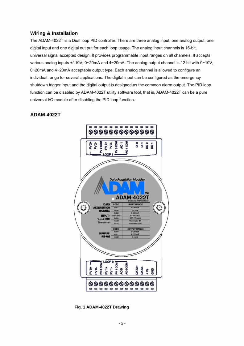
Wiring & Installation The ADAM-4022T is a Dual loop PID controller. There are three analog input, one analog output, one
digital input and one digital out put for each loop usage. The analog input channels is 16-bit,
universal signal accepted design. It provides programmable input ranges on all channels. It accepts
various analog inputs +/-10V, 0~20mA and 4~20mA. The analog output channel is 12 bit with 0~10V,
0~20mA and 4~20mA acceptable output type. Each analog channel is allowed to configure an
individual range for several applications. The digital input can be configured as the emergency
shutdown trigger input and the digital output is designed as the common alarm output. The PID loop
function can be disabled by ADAM-4022T utility software tool, that is, ADAM-4022T can be a pure
universal I/O module after disabling the PID loop function.
ADAM-4022T
Fig. 1 ADAM-4022T Drawing
- 6 -
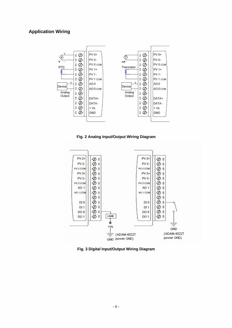
Application Wiring
Fig. 2 Analog Input/Output Wiring Diagram
Fig. 3 Digital Input/Output Wiring Diagram
- 7 -
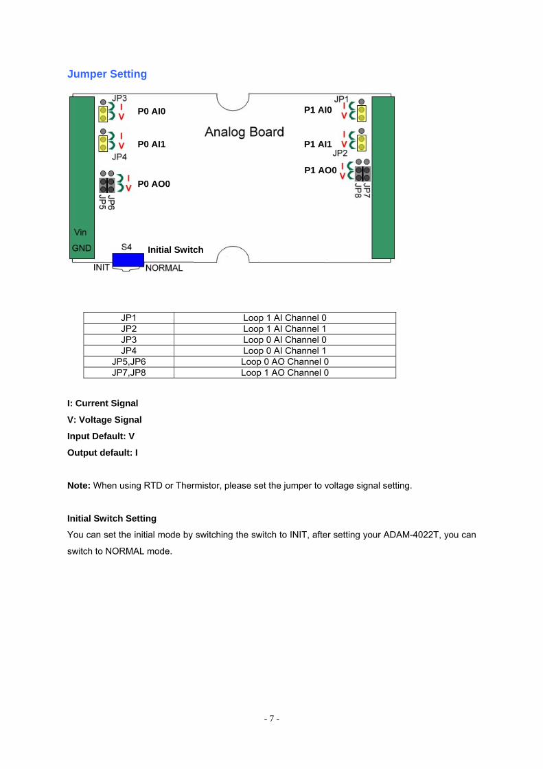
Jumper Setting
JP1 Loop 1 AI Channel 0 JP2 Loop 1 AI Channel 1 JP3 Loop 0 AI Channel 0 JP4 Loop 0 AI Channel 1
JP5,JP6 Loop 0 AO Channel 0 JP7,JP8 Loop 1 AO Channel 0
I: Current Signal
V: Voltage Signal
Input Default: V
Output default: I
Note: When using RTD or Thermistor, please set the jumper to voltage signal setting.
Initial Switch Setting
You can set the initial mode by switching the switch to INIT, after setting your ADAM-4022T, you can
switch to NORMAL mode.
P0 AI0
P0 AI1
P0 AO0
P1 AI0
P1 AI1
P1 AO0
Initial Switch
- 8 -
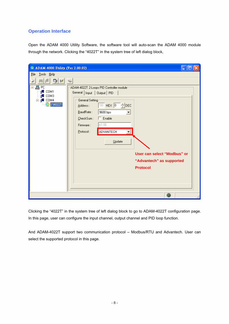
Operation Interface
Open the ADAM 4000 Utility Software, the software tool will auto-scan the ADAM 4000 module
through the network. Clicking the “4022T” in the system tree of left dialog block,
Clicking the “4022T” in the system tree of left dialog block to go to ADAM-4022T configuration page.
In this page, user can configure the input channel, output channel and PID loop function.
And ADAM-4022T support two communication protocol – Modbus/RTU and Advantech. User can
select the supported protocol in this page.
User can select “Modbus” or
“Advantech” as supported
Protocol
- 9 -
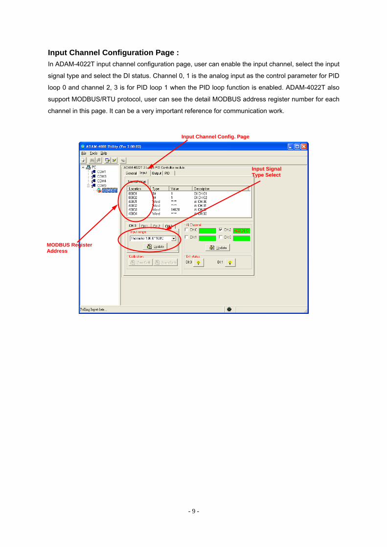
Input Channel Configuration Page : In ADAM-4022T input channel configuration page, user can enable the input channel, select the input
signal type and select the DI status. Channel 0, 1 is the analog input as the control parameter for PID
loop 0 and channel 2, 3 is for PID loop 1 when the PID loop function is enabled. ADAM-4022T also
support MODBUS/RTU protocol, user can see the detail MODBUS address register number for each
channel in this page. It can be a very important reference for communication work.
Input Channel Config. Page
MODBUS Register Address
Input Signal Type Select
- 10 -
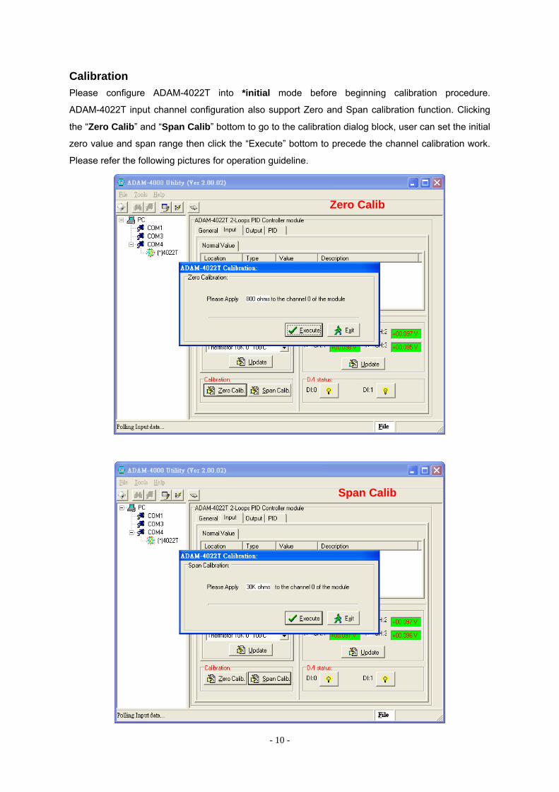
Calibration Please configure ADAM-4022T into *initial mode before beginning calibration procedure.
ADAM-4022T input channel configuration also support Zero and Span calibration function. Clicking
the “Zero Calib” and “Span Calib” bottom to go to the calibration dialog block, user can set the initial
zero value and span range then click the “Execute” bottom to precede the channel calibration work.
Please refer the following pictures for operation guideline.
Zero Calib
Span Calib
- 11 -
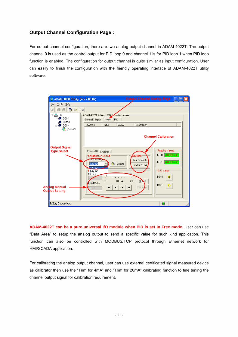
Output Channel Configuration Page :
For output channel configuration, there are two analog output channel in ADAM-4022T. The output
channel 0 is used as the control output for PID loop 0 and channel 1 is for PID loop 1 when PID loop
function is enabled. The configuration for output channel is quite similar as input configuration. User
can easily to finish the configuration with the friendly operating interface of ADAM-4022T utility
software.
ADAM-4022T can be a pure universal I/O module when PID is set in Free mode. User can use
“Data Area” to setup the analog output to send a specific value for such kind application. This
function can also be controlled with MODBUS/TCP protocol through Ethernet network for
HMI/SCADA application.
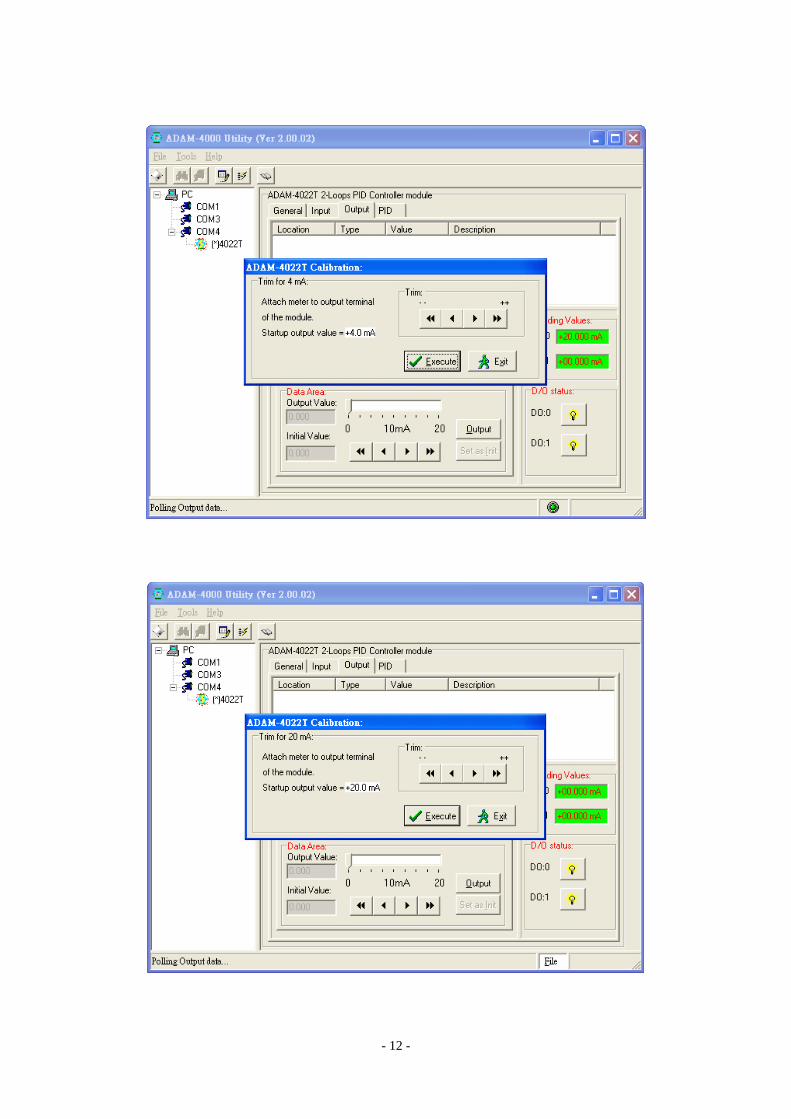
For calibrating the analog output channel, user can use external certificated signal measured device
as calibrator then use the “Trim for 4mA” and “Trim for 20mA” calibrating function to fine tuning the
channel output signal for calibration requirement.
Output Signal Type Select
Channel Calibration
Analog Manual Output Setting
Output Channel Config. Page
- 12 -
- 13 -
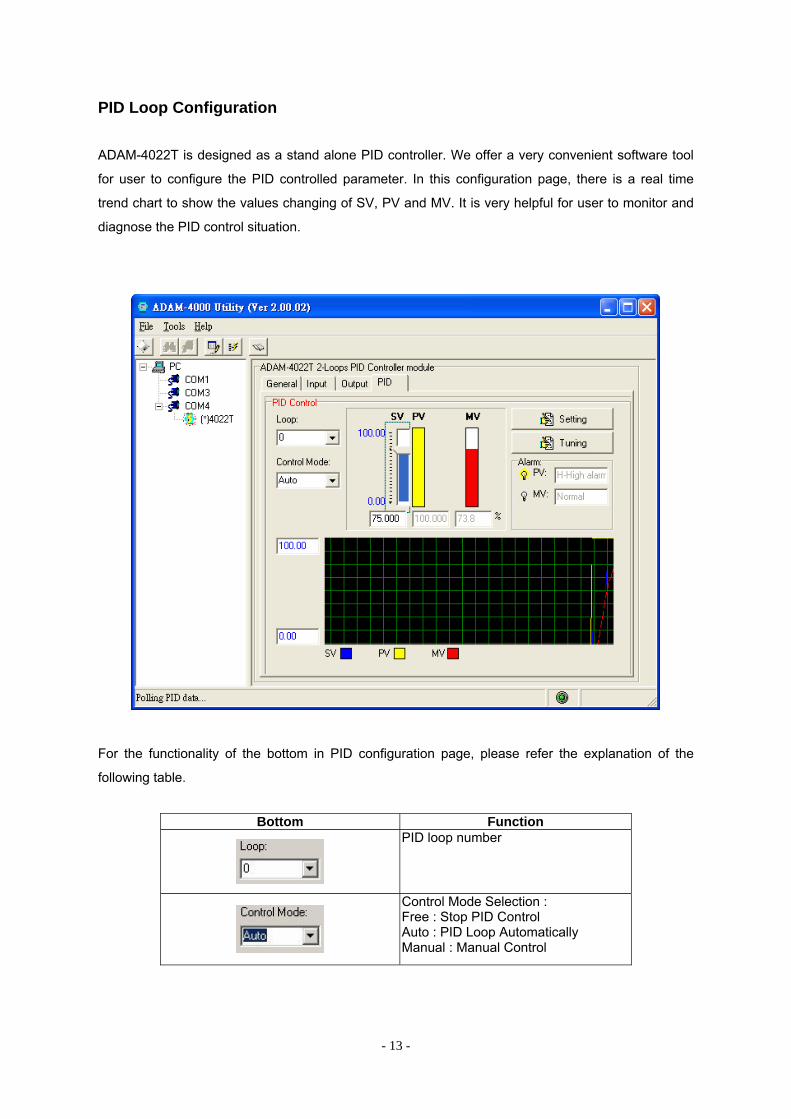
PID Loop Configuration
ADAM-4022T is designed as a stand alone PID controller. We offer a very convenient software tool
for user to configure the PID controlled parameter. In this configuration page, there is a real time
trend chart to show the values changing of SV, PV and MV. It is very helpful for user to monitor and
diagnose the PID control situation.
For the functionality of the bottom in PID configuration page, please refer the explanation of the
following table.
Bottom Function
PID loop number
Control Mode Selection : Free : Stop PID Control Auto : PID Loop Automatically Manual : Manual Control
- 14 -
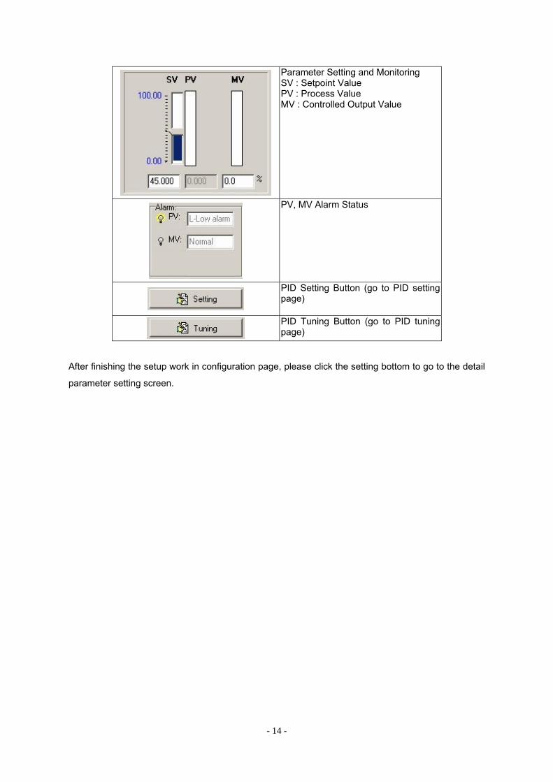
Parameter Setting and Monitoring SV : Setpoint Value PV : Process Value MV : Controlled Output Value
PV, MV Alarm Status
PID Setting Button (go to PID setting page)
PID Tuning Button (go to PID tuning page)
After finishing the setup work in configuration page, please click the setting bottom to go to the detail
parameter setting screen.
- 15 -
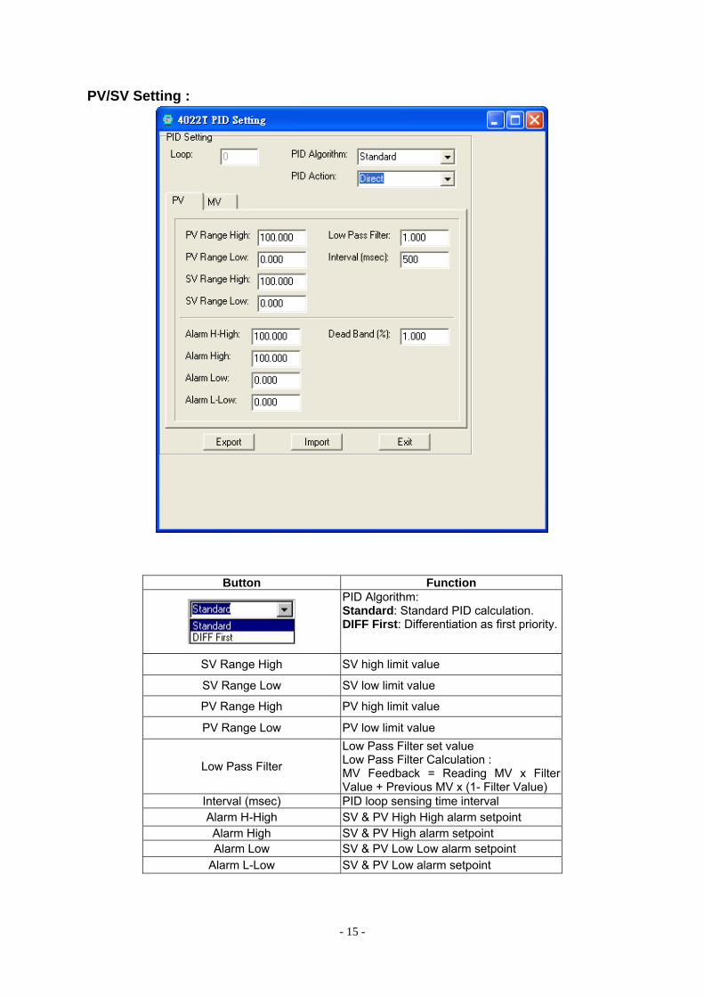
PV/SV Setting :
Button Function
PID Algorithm: Standard: Standard PID calculation. DIFF First: Differentiation as first priority.
SV Range High SV high limit value
SV Range Low SV low limit value
PV Range High PV high limit value
PV Range Low PV low limit value
Low Pass Filter
Low Pass Filter set value Low Pass Filter Calculation : MV Feedback = Reading MV x Filter Value + Previous MV x (1- Filter Value)
Interval (msec) PID loop sensing time interval Alarm H-High SV & PV High High alarm setpoint Alarm High SV & PV High alarm setpoint Alarm Low SV & PV Low Low alarm setpoint
Alarm L-Low SV & PV Low alarm setpoint
- 16 -
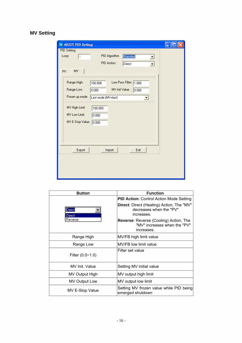
MV Setting
Button Function
PID Action: Control Action Mode Setting Direct: Direct (Heating) Action, The "MV"
decreases when the "PV" increases.
Reverse: Reverse (Cooling) Action, The "MV" increases when the "PV" increases.
Range High MV/FB high limit value
Range Low MV/FB low limit value
Filter (0.0~1.0) Filter set value
MV Init. Value Setting MV initial value
MV Output High MV output high limit
MV Output Low MV output low limit
MV E-Stop Value Setting MV frozen value while PID being emerged shutdown
- 17 -
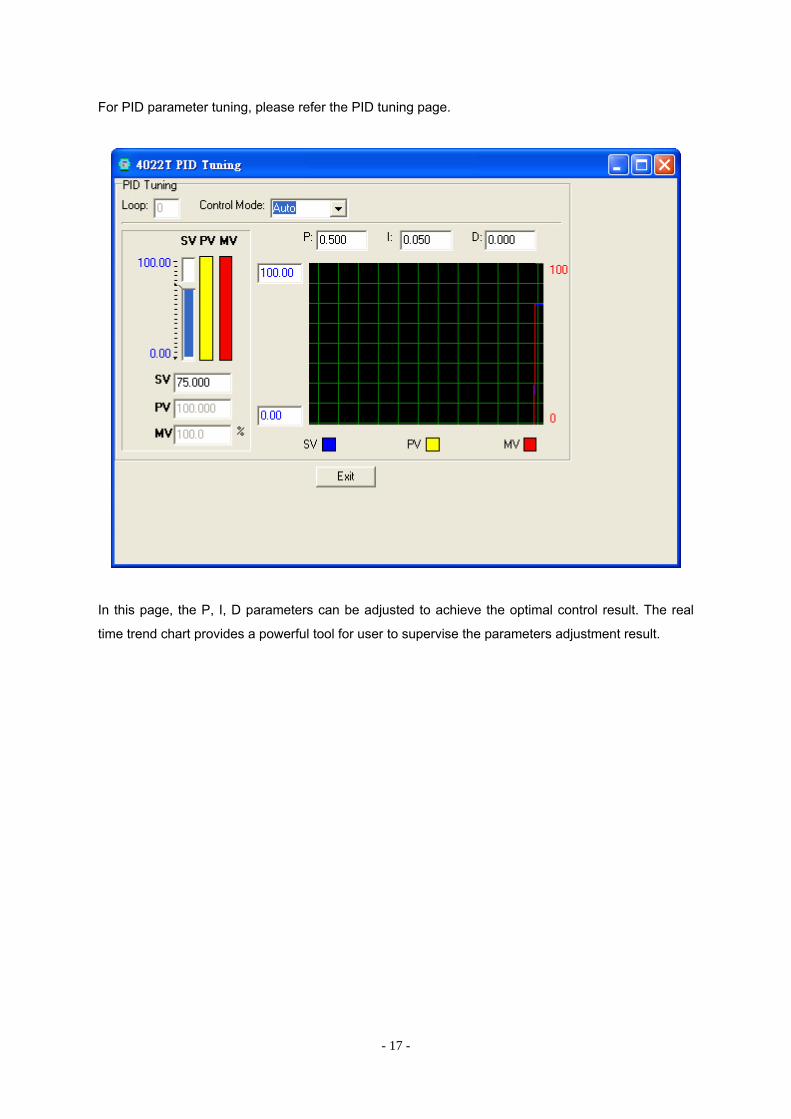
For PID parameter tuning, please refer the PID tuning page.
In this page, the P, I, D parameters can be adjusted to achieve the optimal control result. The real
time trend chart provides a powerful tool for user to supervise the parameters adjustment result.
- 18 -
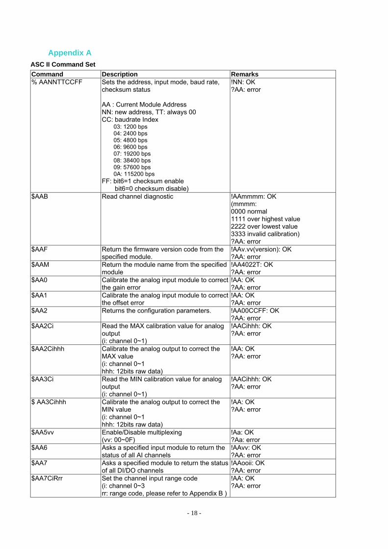
Appendix A ASC II Command Set Command Description Remarks % AANNTTCCFF Sets the address, input mode, baud rate,
checksum status AA : Current Module Address NN: new address, TT: always 00 CC: baudrate Index
03: 1200 bps 04: 2400 bps 05: 4800 bps 06: 9600 bps 07: 19200 bps 08: 38400 bps 09: 57600 bps 0A: 115200 bps
FF: bit6=1 checksum enable bit6=0 checksum disable)
!NN: OK ?AA: error
$AAB Read channel diagnostic
!AAmmmm: OK (mmmm: 0000 normal 1111 over highest value 2222 over lowest value 3333 invalid calibration) ?AA: error
$AAF
Return the firmware version code from the specified module.
!AAv.vv(version): OK ?AA: error
$AAM
Return the module name from the specified module
!AA4022T: OK ?AA: error
$AA0 Calibrate the analog input module to correct the gain error
!AA: OK ?AA: error
$AA1 Calibrate the analog input module to correct the offset error
!AA: OK ?AA: error
$AA2 Returns the configuration parameters. !AA00CCFF: OK ?AA: error
$AA2Ci Read the MAX calibration value for analog output (i: channel 0~1)
!AACihhh: OK ?AA: error
$AA2Cihhh Calibrate the analog output to correct the MAX value (i: channel 0~1 hhh: 12bits raw data)
!AA: OK ?AA: error
$AA3Ci Read the MIN calibration value for analog output (i: channel 0~1)
!AACihhh: OK ?AA: error
$ AA3Cihhh Calibrate the analog output to correct the MIN value (i: channel 0~1 hhh: 12bits raw data)
!AA: OK ?AA: error
$AA5vv Enable/Disable multiplexing (vv: 00~0F)
!Aa: OK ?Aa: error
$AA6 Asks a specified input module to return the status of all AI channels
!AAvv: OK ?AA: error
$AA7 Asks a specified module to return the status of all DI/DO channels
!AAooii: OK ?AA: error
$AA7CiRrr Set the channel input range code (i: channel 0~3 rr: range code, please refer to Appendix B )
!AA: OK ?AA: error
- 19 -
$AA8Ci Read the channel input range code (i: channel 0~3)
!AACiRrr: OK ?AA: error
$AA9Ci Read the channel output range code (i: channel 0~1)
!AACiRrr: OK ?AA: error
$AA9CiRrr Set the channel output range code. After setting, the output will be set to minimum value. (i: channel 0~1 rr: range code)
!AA: OK ?AA: error
#AA Return the input values from all channels of the specified analog input module
>+xx.xxx+xx.xxx+xx.xxx+xx.xxx: OK (format: V, mA is xx.xxx; RTD, Thermistor is xxx.xx) ?AA: error
#AAi Return the input value from the specified channel in the analog input module (i: channel 0~3)
>+xx.xxx: OK ?AA: error
#AAccdd Set a single or all digital output channels. (cc: 00 all channel, dd: 00~03 10 channel 0, dd:00~01 11 channel 1, dd:00~01)
>: OK ?AA: error
#AACidd.ddd Analog output to the specified channel (i: channel 0~1 dd.ddd: engineering units)
>: OK ?AA: error
#AAO Read all AO channel value >+xx.xxx+xx.xxx: OK ?AA: error
#AAOi Read AO value from an output channel (i: channel 0~1)
>: OK ?AA: error
#AAPRsscc Read PID value (ss: starting index, Loop 0 : 00h~4Fh,
Loop 1 : 80h~CFh cc: total to read data - MAX. 64 data can be read in once) * Please refer the below “PID Value Index Table.
>aaaaaaaabbbbbbbb…: OK each value use 8 HEX to indicate a long value ?AA: error
#AAPWssvvvvvvvv Set PID value (ss: index, 00h~FFh vvvvvvvv: the long value) * Please refer the below “PID Value Index Table.
>: OK ?AA: error
- 20 -
#AAPRsscc Name Read PID value Description The command requests and read the PID value like as Process value at address AA. Syntax #AAPRsscc (cr)
# is a delimiter character. AA (range 00-FF) represents the 2-character hexadecimal address that you want to interrogate. PR is the Read PID value command. ss: starting index, Loop 0 : 00h~4Fh
Loop 1 : 80h~CFh
cc: total to read the number of index data - MAX. 64 data can be read in once (cr) is the terminating character, carriage return (0Dh).
Response >aaaaaaaabbbbbbbb….. if the command is valid. ?AA(cr)if an invalid operation was entered. There is no response if the module detects a syntax error or communication error or if the specified address does not exist. > delimiter character indicates a valid command was received. ? delimiter character indicates the command was invalid. aaaaaaaabbbbbbbb is the two HEX long value due to each value use 8 HEX to indicate a long value
Example command: #01PR0402(cr) response: >00001FFF000002FF The command reads the data of Process value_1 bare data and Process value_2 bare at address 01h due to 0402 means starting index is Process value_1 and total data is 2. User can refer PID Value Index Table for ASCII Mode The Process value_1 bare data and Process value_2 bare at address 01h respond with 00001FFF000002FF(HEX). It means Process value_1 bare data is 8.191(Decimal) and Process value_2 bare data is 0.767(Decimal) due to their Decimal place is 3
- 21 -
#AAPWssvvvvvvvv Name Set PID value Description The command sets the PID value like as setting of Manual/Free/PID mode at
address AA. Syntax #AAPWssvvvvvvvv (cr)
# is a delimiter character. AA (range 00-FF) represents the 2-character hexadecimal address that you want to interrogate. PW is the Set PID value command. ss: index, Loop 0 : 00h~4Fh
Loop 1 : 80h~CFh
vvvvvvvv: the long value, please refer the below “PID Value Index Table (cr) is the terminating character, carriage return (0Dh).
Response > if the command is valid. ?AA(cr)if an invalid operation was entered. There is no response if the module detects a syntax error or communication error or if the specified address does not exist. > delimiter character indicates a valid command was received. ? delimiter character indicates the command was invalid.
Example command: #01PW0000000002(cr) response: > The command sets Loop 1 as “manual mode”due to 00 is the index no and 00000002 is to select the Manual mode. User can refer PID Value Index Table for ASCII Mode
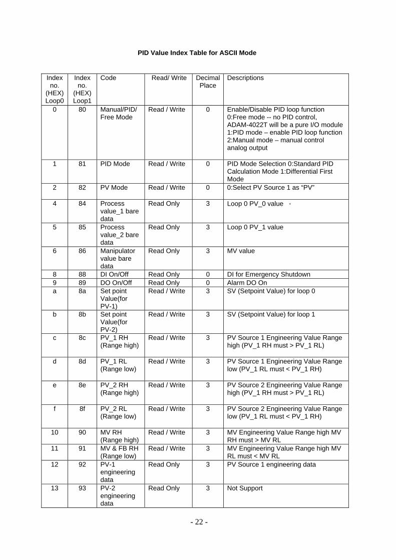
PID Value Index Table for ASCII Mode
Index no.
(HEX) Loop0
Index no.
(HEX) Loop1
Code Read/ Write Decimal Place
Descriptions
0 80 Manual/PID/ Free Mode
Read / Write 0 Enable/Disable PID loop function 0:Free mode -- no PID control, ADAM-4022T will be a pure I/O module 1:PID mode – enable PID loop function 2:Manual mode – manual control analog output
1 81 PID Mode Read / Write 0 PID Mode Selection 0:Standard PID Calculation Mode 1:Differential First Mode
2 82 PV Mode Read / Write 0 0:Select PV Source 1 as “PV”
4 84 Process value_1 bare data
Read Only 3 Loop 0 PV_0 value 。
5 85 Process value_2 bare data
Read Only 3 Loop 0 PV_1 value
6 86 Manipulator value bare data
Read Only 3 MV value
8 88 DI On/Off Read Only 0 DI for Emergency Shutdown 9 89 DO On/Off Read Only 0 Alarm DO On a 8a Set point
Value(for PV-1)
Read / Write 3 SV (Setpoint Value) for loop 0
b 8b Set point Value(for PV-2)
Read / Write 3 SV (Setpoint Value) for loop 1
c 8c PV_1 RH (Range high)
Read / Write 3 PV Source 1 Engineering Value Range high (PV_1 RH must > PV_1 RL)
d 8d PV_1 RL (Range low)
Read / Write 3 PV Source 1 Engineering Value Range low (PV_1 RL must < PV_1 RH)
e 8e PV_2 RH (Range high)
Read / Write 3 PV Source 2 Engineering Value Range high (PV_1 RH must > PV_1 RL)
f 8f PV_2 RL (Range low)
Read / Write 3 PV Source 2 Engineering Value Range low (PV_1 RL must < PV_1 RH)
10 90 MV RH (Range high)
Read / Write 3 MV Engineering Value Range high MV RH must > MV RL
11 91 MV & FB RH (Range low)
Read / Write 3 MV Engineering Value Range high MV RL must < MV RL
12 92 PV-1 engineering data
Read Only 3 PV Source 1 engineering data
13 93 PV-2 engineering data
Read Only 3 Not Support
- 22 -
- 23 -
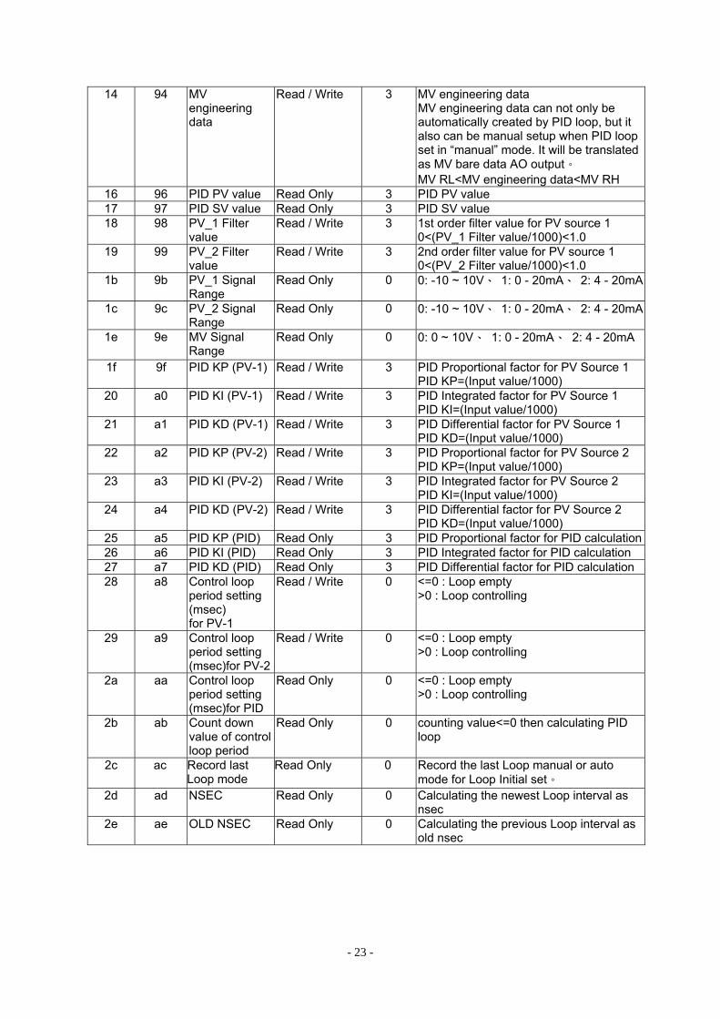
14 94 MV engineering data
Read / Write 3 MV engineering data MV engineering data can not only be automatically created by PID loop, but it also can be manual setup when PID loop set in “manual” mode. It will be translated as MV bare data AO output。 MV RL<MV engineering data<MV RH
16 96 PID PV value Read Only 3 PID PV value 17 97 PID SV value Read Only 3 PID SV value 18 98 PV_1 Filter
value Read / Write 3 1st order filter value for PV source 1
0<(PV_1 Filter value/1000)<1.0 19 99 PV_2 Filter
value Read / Write 3 2nd order filter value for PV source 1
0<(PV_2 Filter value/1000)<1.0 1b 9b PV_1 Signal
Range Read Only 0 0: -10 ~ 10V、 1: 0 - 20mA、 2: 4 - 20mA
1c 9c PV_2 Signal Range
Read Only 0 0: -10 ~ 10V、 1: 0 - 20mA、 2: 4 - 20mA
1e 9e MV Signal Range
Read Only 0 0: 0 ~ 10V、 1: 0 - 20mA、 2: 4 - 20mA
1f 9f PID KP (PV-1) Read / Write 3 PID Proportional factor for PV Source 1 PID KP=(Input value/1000)
20 a0 PID KI (PV-1) Read / Write 3 PID Integrated factor for PV Source 1 PID KI=(Input value/1000)
21 a1 PID KD (PV-1) Read / Write 3 PID Differential factor for PV Source 1 PID KD=(Input value/1000)
22 a2 PID KP (PV-2) Read / Write 3 PID Proportional factor for PV Source 2 PID KP=(Input value/1000)
23 a3 PID KI (PV-2) Read / Write 3 PID Integrated factor for PV Source 2 PID KI=(Input value/1000)
24 a4 PID KD (PV-2) Read / Write 3 PID Differential factor for PV Source 2 PID KD=(Input value/1000)
25 a5 PID KP (PID) Read Only 3 PID Proportional factor for PID calculation26 a6 PID KI (PID) Read Only 3 PID Integrated factor for PID calculation 27 a7 PID KD (PID) Read Only 3 PID Differential factor for PID calculation28 a8 Control loop
period setting (msec) for PV-1
Read / Write 0 <=0 : Loop empty >0 : Loop controlling
29 a9 Control loop period setting (msec)for PV-2
Read / Write 0 <=0 : Loop empty >0 : Loop controlling
2a aa Control loop period setting (msec)for PID
Read Only 0 <=0 : Loop empty >0 : Loop controlling
2b ab Count down value of control loop period
Read Only 0 counting value<=0 then calculating PID loop
2c ac Record last Loop mode
Read Only 0 Record the last Loop manual or auto mode for Loop Initial set。
2d ad NSEC Read Only 0 Calculating the newest Loop interval as nsec
2e ae OLD NSEC Read Only 0 Calculating the previous Loop interval as old nsec
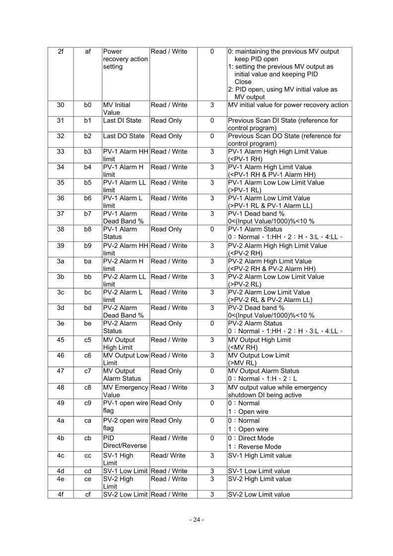
- 24 -
2f af Power recovery action setting
Read / Write 0 0: maintaining the previous MV output keep PID open
1: setting the previous MV output as initial value and keeping PID Close
2: PID open, using MV initial value as MV output
30 b0 MV Initial Value
Read / Write 3 MV initial value for power recovery action
31 b1 Last DI State Read Only 0 Previous Scan DI State (reference for control program)
32 b2 Last DO State Read Only 0 Previous Scan DO State (reference for control program)
33 b3 PV-1 Alarm HH limit
Read / Write 3 PV-1 Alarm High High Limit Value (<PV-1 RH)
34 b4 PV-1 Alarm H limit
Read / Write 3 PV-1 Alarm High Limit Value (<PV-1 RH & PV-1 Alarm HH)
35 b5 PV-1 Alarm LL limit
Read / Write 3 PV-1 Alarm Low Low Limit Value (>PV-1 RL)
36 b6 PV-1 Alarm L limit
Read / Write 3 PV-1 Alarm Low Limit Value (>PV-1 RL & PV-1 Alarm LL)
37 b7 PV-1 Alarm Dead Band %
Read / Write 3 PV-1 Dead band % 0<(Input Value/1000)%<10 %
38 b8 PV-1 Alarm Status
Read Only 0 PV-1 Alarm Status 0:Normal、1:HH、2:H、3:L、4:LL。
39 b9 PV-2 Alarm HH limit
Read / Write 3 PV-2 Alarm High High Limit Value (<PV-2 RH)
3a ba PV-2 Alarm H limit
Read / Write 3 PV-2 Alarm High Limit Value (<PV-2 RH & PV-2 Alarm HH)
3b bb PV-2 Alarm LL limit
Read / Write 3 PV-2 Alarm Low Low Limit Value (>PV-2 RL)
3c bc PV-2 Alarm L limit
Read / Write 3 PV-2 Alarm Low Limit Value (>PV-2 RL & PV-2 Alarm LL)
3d bd PV-2 Alarm Dead Band %
Read / Write 3 PV-2 Dead band % 0<(Input Value/1000)%<10 %
3e be PV-2 Alarm Status
Read Only 0 PV-2 Alarm Status 0:Normal、1:HH、2:H、3:L、4:LL。
45 c5 MV Output High Limit
Read / Write 3 MV Output High Limit (<MV RH)
46 c6 MV Output Low Limit
Read / Write 3 MV Output Low Limit (>MV RL)
47 c7 MV Output Alarm Status
Read Only 0 MV Output Alarm Status 0:Normal、1:H、2:L
48 c8 MV Emergency Value
Read / Write 3 MV output value while emergency shutdown DI being active
49 c9 PV-1 open wire flag
Read Only 0 0:Normal 1:Open wire
4a ca PV-2 open wire flag
Read Only 0 0:Normal 1:Open wire
4b cb PID Direct/Reverse
Read / Write 0 0:Direct Mode 1:Reverse Mode
4c cc SV-1 High Limit
Read/ Write 3 SV-1 High Limit value
4d cd SV-1 Low Limit Read / Write 3 SV-1 Low Limit value 4e ce SV-2 High
Limit Read / Write 3 SV-2 High Limit value
4f cf SV-2 Low Limit Read / Write 3 SV-2 Low Limit value
- 25 -
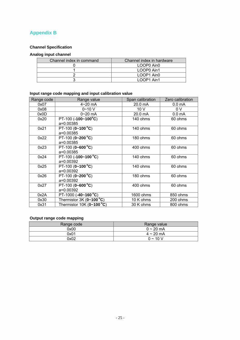
Appendix B
Channel Specification
Analog input channel Channel index in command Channel index in hardware
0 LOOP0 Ain0 1 LOOP0 Ain1 2 LOOP1 Ain0 3 LOOP1 Ain1
Input range code mapping and input calibration value Range code Range value Span calibration Zero calibration
0x07 4~20 mA 20.0 mA 0.0 mA 0x08 0~10 V 10 V 0 V 0x0D 0~20 mA 20.0 mA 0.0 mA 0x20 PT-100 (-100~100oC)
a=0.00385 140 ohms 60 ohms
0x21 PT-100 (0~100 oC) a=0.00385
140 ohms 60 ohms
0x22 PT-100 (0~200 oC) a=0.00385
180 ohms 60 ohms
0x23 PT-100 (0~600 oC) a=0.00385
400 ohms 60 ohms
0x24 PT-100 (-100~100 oC) a=0.00392
140 ohms 60 ohms
0x25 PT-100 (0~100 oC) a=0.00392
140 ohms 60 ohms
0x26 PT-100 (0~200 oC) a=0.00392
180 ohms 60 ohms
0x27 PT-100 (0~600 oC) a=0.00392
400 ohms 60 ohms
0x2A PT-1000 (-40~160 oC) 1600 ohms 850 ohms 0x30 Thermistor 3K (0~100 oC) 10 K ohms 200 ohms 0x31 Thermistor 10K (0~100 oC) 30 K ohms 800 ohms
Output range code mapping Range code Range value
0x00 0 ~ 20 mA 0x01 4 ~ 20 mA 0x02 0 ~ 10 V
- 26 -
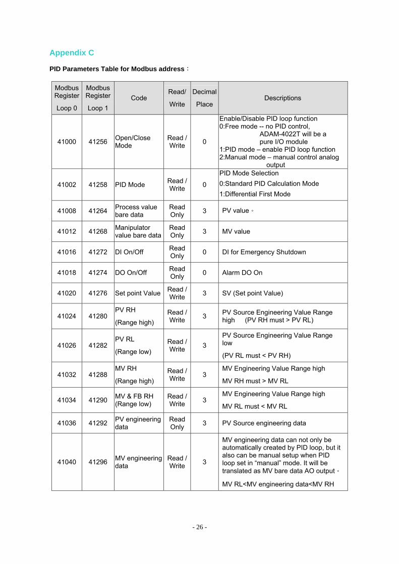
Appendix C
PID Parameters Table for Modbus address:
Modbus Register
Loop 0
Modbus Register
Loop 1 Code
Read/
Write
Decimal
PlaceDescriptions
41000 41256 Open/Close Mode
Read / Write 0
Enable/Disable PID loop function 0:Free mode -- no PID control,
ADAM-4022T will be a pure I/O module
1:PID mode – enable PID loop function 2:Manual mode – manual control analog
output
41002 41258 PID Mode Read / Write 0
PID Mode Selection 0:Standard PID Calculation Mode 1:Differential First Mode
41008 41264 Process value bare data
Read Only 3 PV value。
41012 41268 Manipulator value bare data
Read Only 3 MV value
41016 41272 DI On/Off Read Only 0 DI for Emergency Shutdown
41018 41274 DO On/Off Read Only 0 Alarm DO On
41020 41276 Set point Value Read / Write 3 SV (Set point Value)
41024 41280 PV RH
(Range high) Read / Write 3 PV Source Engineering Value Range
high (PV RH must > PV RL)
41026 41282 PV RL
(Range low) Read / Write 3
PV Source Engineering Value Range low
(PV RL must < PV RH)
41032 41288 MV RH
(Range high) Read / Write 3
MV Engineering Value Range high
MV RH must > MV RL
41034 41290 MV & FB RH (Range low)
Read / Write 3
MV Engineering Value Range high
MV RL must < MV RL
41036 41292 PV engineering data
Read Only 3 PV Source engineering data
41040 41296 MV engineering data
Read / Write 3
MV engineering data can not only be automatically created by PID loop, but it also can be manual setup when PID loop set in “manual” mode. It will be translated as MV bare data AO output。
MV RL<MV engineering data<MV RH
- 27 -
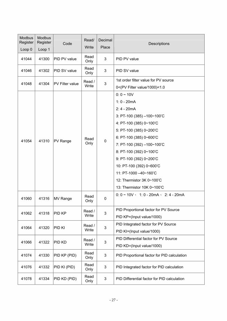
Modbus Register
Loop 0
Modbus Register
Loop 1 Code
Read/
Write
Decimal
Place Descriptions
41044 41300 PID PV value Read Only 3 PID PV value
41046 41302 PID SV value Read Only 3 PID SV value
41048 41304 PV Filter value Read / Write 3
1st order filter value for PV source
0<(PV Filter value/1000)<1.0
41054 41310 PV Range Read Only 0
0: 0 ~ 10V
1: 0 - 20mA
2: 4 - 20mA
3: PT-100 (385) –100~100’C
4: PT-100 (385) 0~100’C
5: PT-100 (385) 0~200’C
6: PT-100 (385) 0~600’C
7: PT-100 (392) –100~100’C
8: PT-100 (392) 0~100’C
9: PT-100 (392) 0~200’C
10: PT-100 (392) 0~600’C
11: PT-1000 –40~160’C
12: Thermistor 3K 0~100’C
13: Thermistor 10K 0~100’C
41060 41316 MV Range Read Only 0
0: 0 ~ 10V、 1: 0 - 20mA、 2: 4 - 20mA
41062 41318 PID KP Read / Write 3
PID Proportional factor for PV Source
PID KP=(Input value/1000)
41064 41320 PID KI Read / Write 3
PID Integrated factor for PV Source
PID KI=(Input value/1000)
41066 41322 PID KD Read / Write 3
PID Differential factor for PV Source
PID KD=(Input value/1000)
41074 41330 PID KP (PID) Read Only 3 PID Proportional factor for PID calculation
41076 41332 PID KI (PID) Read Only 3 PID Integrated factor for PID calculation
41078 41334 PID KD (PID) Read Only 3 PID Differential factor for PID calculation
- 28 -
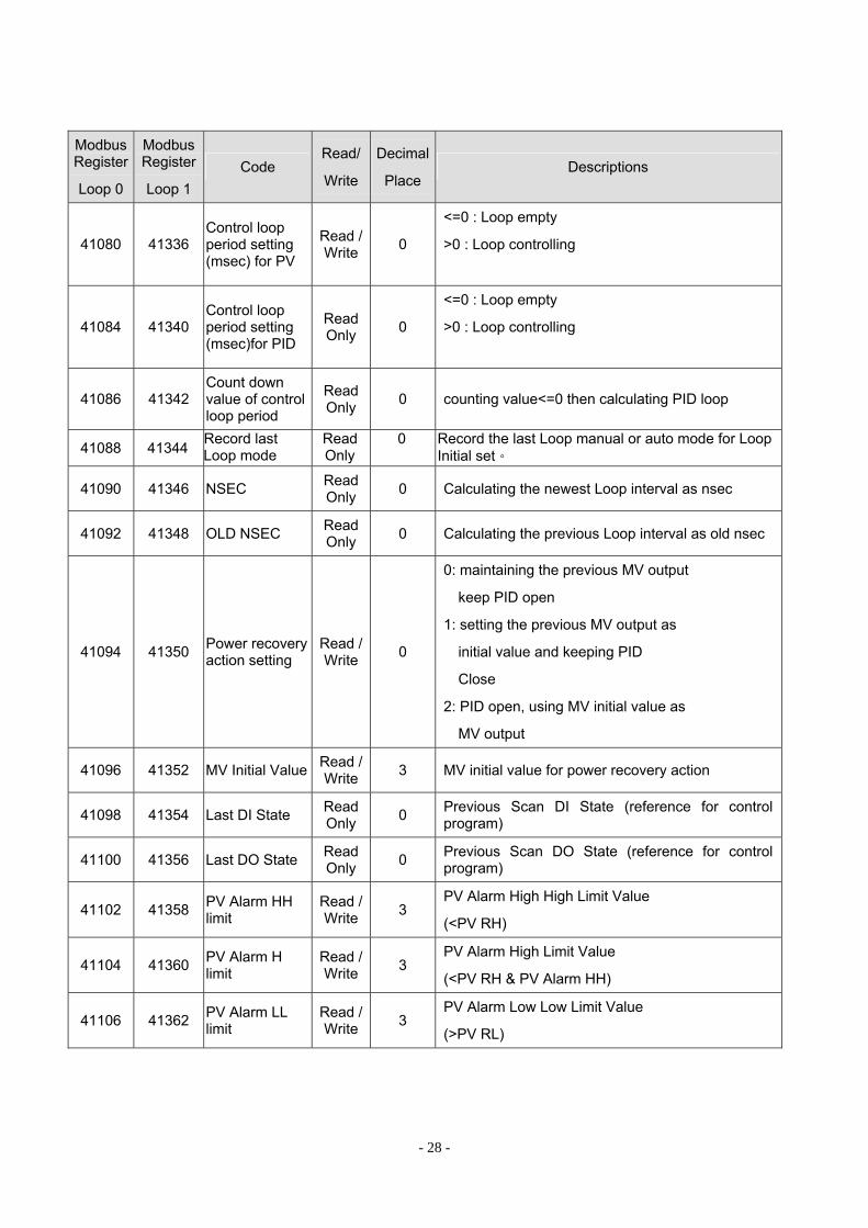
Modbus Register
Loop 0
Modbus Register
Loop 1 Code
Read/
Write
Decimal
Place Descriptions
41080 41336 Control loop period setting (msec) for PV
Read / Write 0
<=0 : Loop empty
>0 : Loop controlling
41084 41340 Control loop period setting (msec)for PID
Read Only 0
<=0 : Loop empty
>0 : Loop controlling
41086 41342 Count down value of control loop period
Read Only 0 counting value<=0 then calculating PID loop
41088 41344 Record last Loop mode
Read Only
0 Record the last Loop manual or auto mode for Loop Initial set。
41090 41346 NSEC Read Only 0 Calculating the newest Loop interval as nsec
41092 41348 OLD NSEC Read Only 0 Calculating the previous Loop interval as old nsec
41094 41350 Power recovery action setting
Read / Write 0
0: maintaining the previous MV output
keep PID open
1: setting the previous MV output as
initial value and keeping PID
Close
2: PID open, using MV initial value as
MV output
41096 41352 MV Initial Value Read / Write 3 MV initial value for power recovery action
41098 41354 Last DI State Read Only 0 Previous Scan DI State (reference for control
program)
41100 41356 Last DO State Read Only 0 Previous Scan DO State (reference for control
program)
41102 41358 PV Alarm HH limit
Read / Write 3
PV Alarm High High Limit Value
(<PV RH)
41104 41360 PV Alarm H limit
Read / Write 3
PV Alarm High Limit Value
(<PV RH & PV Alarm HH)
41106 41362 PV Alarm LL limit
Read / Write 3
PV Alarm Low Low Limit Value
(>PV RL)
- 29 -
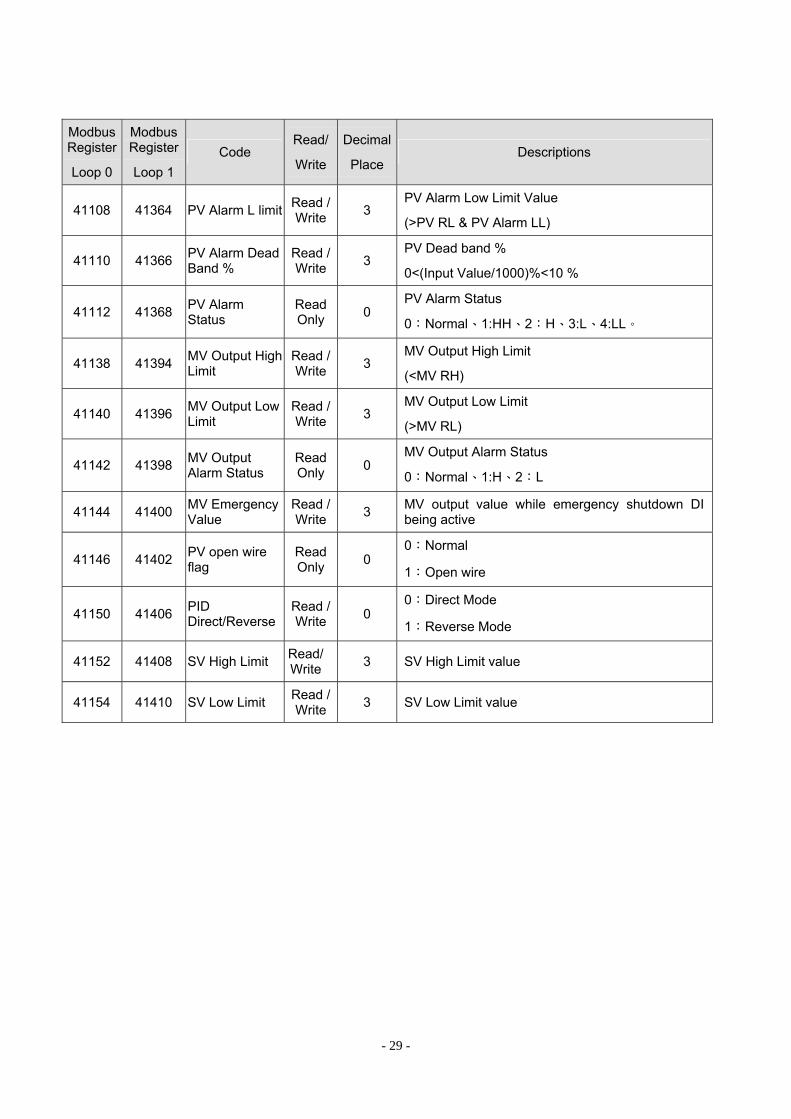
Modbus Register
Loop 0
Modbus Register
Loop 1 Code
Read/
Write
Decimal
Place Descriptions
41108 41364 PV Alarm L limit Read / Write 3
PV Alarm Low Limit Value
(>PV RL & PV Alarm LL)
41110 41366 PV Alarm Dead Band %
Read / Write 3
PV Dead band %
0<(Input Value/1000)%<10 %
41112 41368 PV Alarm Status
Read Only 0
PV Alarm Status
0:Normal、1:HH、2:H、3:L、4:LL。
41138 41394 MV Output High Limit
Read / Write 3
MV Output High Limit
(<MV RH)
41140 41396 MV Output Low Limit
Read / Write 3
MV Output Low Limit
(>MV RL)
41142 41398 MV Output Alarm Status
Read Only 0
MV Output Alarm Status
0:Normal、1:H、2:L
41144 41400 MV Emergency Value
Read / Write 3 MV output value while emergency shutdown DI
being active
41146 41402 PV open wire flag
Read Only 0
0:Normal
1:Open wire
41150 41406 PID Direct/Reverse
Read / Write 0
0:Direct Mode
1:Reverse Mode
41152 41408 SV High Limit Read/ Write 3 SV High Limit value
41154 41410 SV Low Limit Read / Write 3 SV Low Limit value
- 30 -
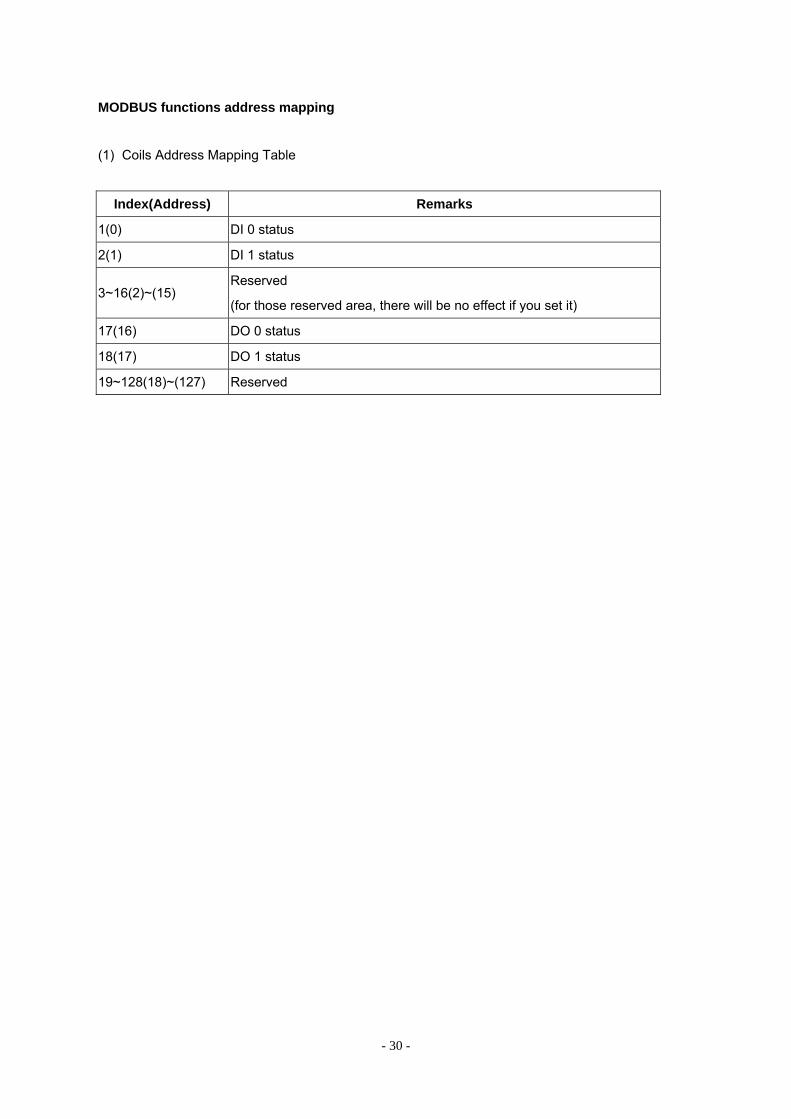
MODBUS functions address mapping
(1) Coils Address Mapping Table
Index(Address) Remarks
1(0) DI 0 status
2(1) DI 1 status
3~16(2)~(15) Reserved
(for those reserved area, there will be no effect if you set it)
17(16) DO 0 status
18(17) DO 1 status
19~128(18)~(127) Reserved
- 31 -
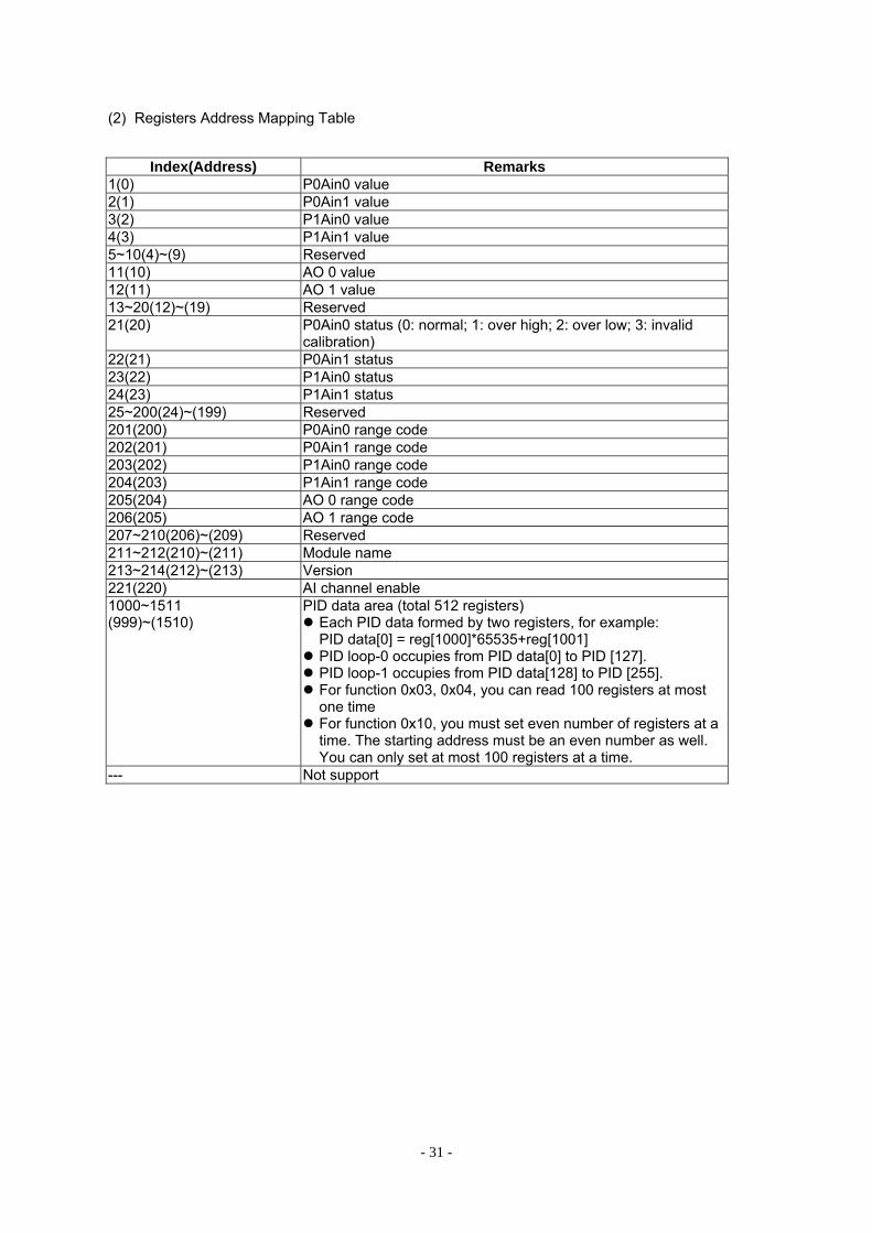
(2) Registers Address Mapping Table
Index(Address) Remarks
1(0) P0Ain0 value 2(1) P0Ain1 value 3(2) P1Ain0 value 4(3) P1Ain1 value 5~10(4)~(9) Reserved 11(10) AO 0 value 12(11) AO 1 value 13~20(12)~(19) Reserved 21(20) P0Ain0 status (0: normal; 1: over high; 2: over low; 3: invalid
calibration) 22(21) P0Ain1 status 23(22) P1Ain0 status 24(23) P1Ain1 status 25~200(24)~(199) Reserved 201(200) P0Ain0 range code 202(201) P0Ain1 range code 203(202) P1Ain0 range code 204(203) P1Ain1 range code 205(204) AO 0 range code 206(205) AO 1 range code 207~210(206)~(209) Reserved 211~212(210)~(211) Module name 213~214(212)~(213) Version 221(220) AI channel enable 1000~1511 (999)~(1510)
PID data area (total 512 registers) Each PID data formed by two registers, for example: PID data[0] = reg[1000]*65535+reg[1001]
PID loop-0 occupies from PID data[0] to PID [127]. PID loop-1 occupies from PID data[128] to PID [255]. For function 0x03, 0x04, you can read 100 registers at most one time
For function 0x10, you must set even number of registers at a time. The starting address must be an even number as well. You can only set at most 100 registers at a time.
--- Not support