Embed Size (px)
Citation preview
ADCA
VALSTEAM ADCA We reserve the right to change the design and material of this product without notice.
IS PRV47-2.20 E 08.15
PILOT OPERATED PRESSURE REDUCING VALVES
PRV47/2 DN65 – DN100
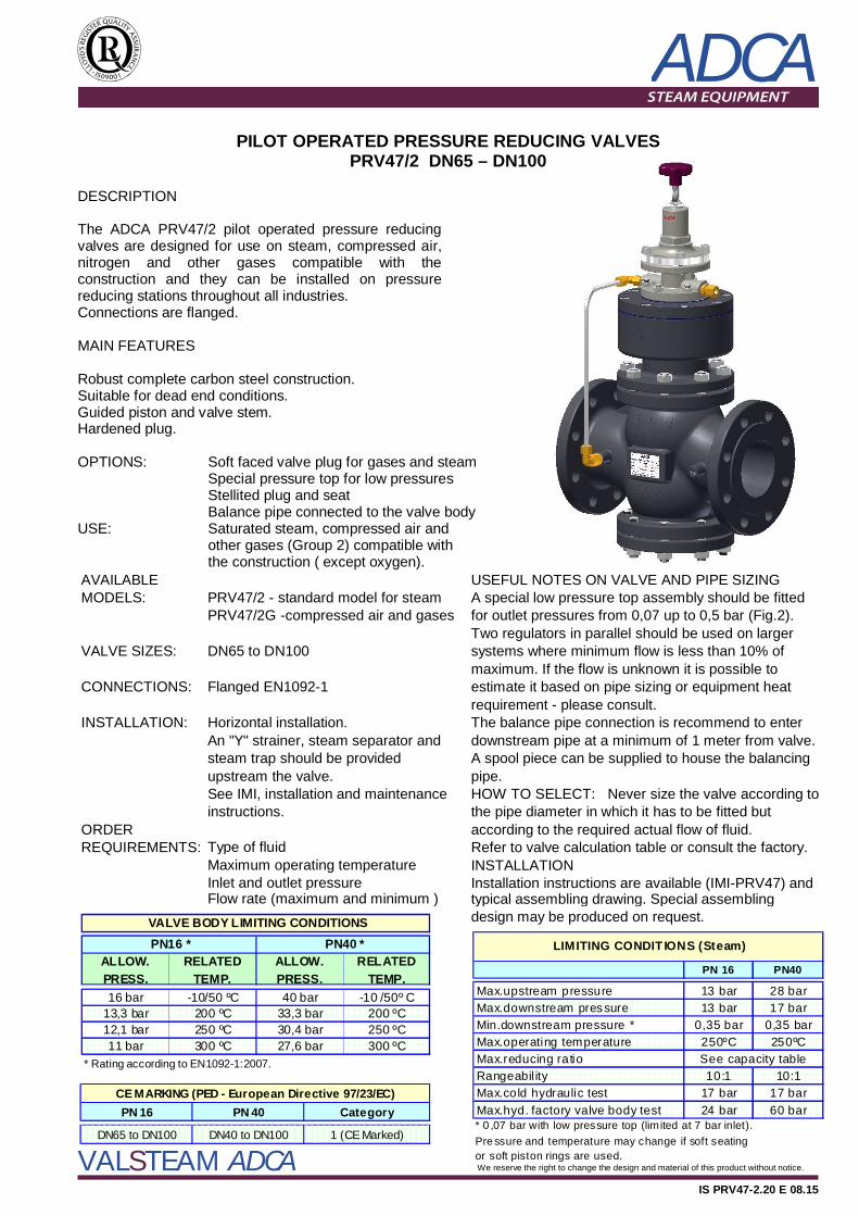
DESCRIPTION The ADCA PRV47/2 pilot operated pressure reducing valves are designed for use on steam, compressed air, nitrogen and other gases compatible with the construction and they can be installed on pressure reducing stations throughout all industries. Connections are flanged. MAIN FEATURES Robust complete carbon steel construction. Suitable for dead end conditions. Guided piston and valve stem. Hardened plug. OPTIONS: USE:
Soft faced valve plug for gases and steam Special pressure top for low pressures Stellited plug and seat Balance pipe connected to the valve body Saturated steam, compressed air and other gases (Group 2) compatible with the construction ( except oxygen).
AVAILABLE USEFUL NOTES ON VALVE AND PIPE SIZINGMODELS: PRV47/2 - standard model for steam A special low pressure top assembly should be fitted
PRV47/2G -compressed air and gases for outlet pressures from 0,07 up to 0,5 bar (Fig.2).Two regulators in parallel should be used on larger
VALVE SIZES: DN65 to DN100 systems where minimum flow is less than 10% ofmaximum. If the flow is unknown it is possible to
CONNECTIONS: Flanged EN1092-1 estimate it based on pipe sizing or equipment heatrequirement - please consult.
INSTALLATION: Horizontal installation. The balance pipe connection is recommend to enterAn "Y" strainer, steam separator and downstream pipe at a minimum of 1 meter from valve.steam trap should be provided A spool piece can be supplied to house the balancingupstream the valve. pipe. See IMI, installation and maintenance HOW TO SELECT:instructions. the pipe diameter in which it has to be fitted but
ORDER according to the required actual flow of fluid.REQUIREMENTS: Type of fluid Refer to valve calculation table or consult the factory.
Maximum operating temperature INSTALLATIONInlet and outlet pressure Installation instructions are available (IMI-PRV47) andFlow rate (maximum and minimum ) typical assembling drawing. Special assembling
design may be produced on request.
Never size the valve according to
VALVE BODY LIMITING CONDITIONS
30,4 bar 250 ºC27,6 bar 300 ºC
PN40 * ALLOW. PRESS.
RELATED TEMP.
16 bar -10/50 ºC 40 bar -10 /50º C33,3 bar 200 ºC
* Rating according to EN1092-1:2007.
12,1 bar 250 ºC13,3 bar 200 ºC
PN16 * ALLOW. PRESS.
RELATED TEMP.
11 bar 300 ºC
PN 16 PN 40 Category
DN65 to DN100 DN40 to DN100 1 (CE Marked)
CE MARKING (PED - European Directive 97/23/EC)
PN 16 PN40
13 bar 28 bar13 bar 17 bar
Min.downstream pressure * 0,35 bar 0,35 bar250ºC 250ºC
10:1 10:1Max.cold hydraulic test 17 bar 17 bar
24 bar 60 bar* 0 ,07 bar with low pressure top (lim ited at 7 bar inlet).Pre ssure and temperature may change if soft seating or soft piston rings are used.
LIMITING CONDIT IONS (Steam)
Max.upstream pressure Max.downstream pressure
Max.operating temperature
Max.hyd. factory valve body test
Rangeabil ityMax.reducing ratio See capacity table
ADCA
VALSTEAM ADCA We reserve the right to change the design and material of this product without notice.
IS PRV47-2.20 E 08.15
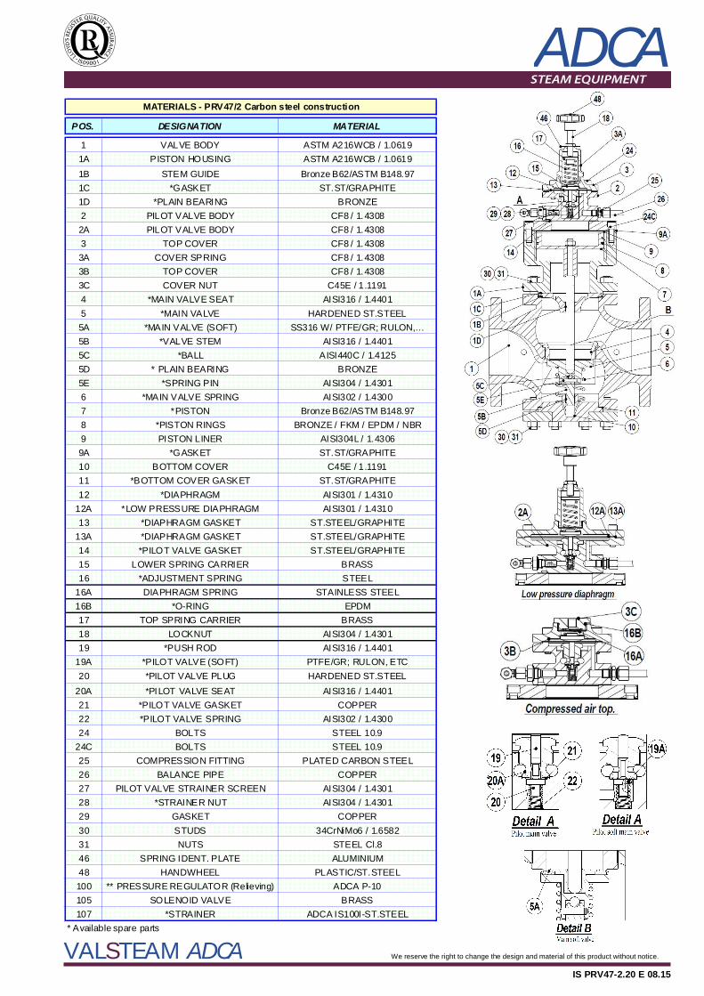
POS. DESIGNATION MATERIAL
1 VALVE BODY ASTM A216WCB / 1.06191A PISTON HOUSING ASTM A216WCB / 1.06191B STEM GUIDE Bronze B62/ASTM B148.971C *GASKET ST.ST/GRAPHITE1D *PLAIN BEARING BRONZE2 PILOT VALVE BODY CF8 / 1.43082A PILOT VALVE BODY CF8 / 1.43083 TOP COVER CF8 / 1.43083A COVER SPRING CF8 / 1.43083B TOP COVER CF8 / 1.43083C COVER NUT C45E / 1.11914 *MAIN VALVE SEAT AISI316 / 1.44015 *MAIN VALVE HARDENED ST.STEEL5A *MAIN VALVE (SOFT) SS316 W/ PTFE/GR; RULON,…5B *VALVE STEM AISI316 / 1.44015C *BALL AISI440C / 1.41255D * PLAIN BEARING BRONZE5E *SPRING PIN AISI304 / 1.43016 *MAIN VALVE SPRING AISI302 / 1.43007 *PISTON Bronze B62/ASTM B148.978 *PISTON RINGS BRONZE / FKM / EPDM / NBR9 PISTON LINER AISI304L / 1.43069A *GASKET ST.ST/GRAPHITE10 BOTTOM COVER C45E / 1.119111 *BOTTOM COVER GASKET ST.ST/GRAPHITE12 *DIAPHRAGM AISI301 / 1.4310
12A *LOW PRESSURE DIAPHRAGM AISI301 / 1.431013 *DIAPHRAGM GASKET ST.STEEL/GRAPHITE
13A *DIAPHRAGM GASKET ST.STEEL/GRAPHITE14 *PILOT VALVE GASKET ST.STEEL/GRAPHITE15 LOWER SPRING CARRIER BRASS16 *ADJUSTMENT SPRING STEEL
16A DIAPHRAGM SPRING STAINLESS STEEL16B *O-RING EPDM17 TOP SPRING CARRIER BRASS18 LOCKNUT AISI304 / 1.430119 *PUSH ROD AISI316 / 1.4401
19A *PILOT VALVE (SOFT) PTFE/GR; RULON, ETC20 *PILOT VALVE PLUG HARDENED ST.STEEL
20A *PILOT VALVE SEAT AISI316 / 1.440121 *PILOT VALVE GASKET COPPER22 *PILOT VALVE SPRING AISI302 / 1.430024 BOLTS STEEL 10.9
24C BOLTS STEEL 10.925 COMPRESSION FITTING PLATED CARBON STEEL26 BALANCE PIPE COPPER27 PILOT VALVE STRAINER SCREEN AISI304 / 1.430128 *STRAINER NUT AISI304 / 1.430129 GASKET COPPER30 STUDS 34CrNiMo6 / 1.658231 NUTS STEEL Cl.846 SPRING IDENT. PLATE ALUMINIUM48 HANDWHEEL PLASTIC/ST.STEEL100 ** PRESSURE REGULATOR (Relieving) ADCA P-10105 SOLENOID VALVE BRASS107 *STRAINER ADCA IS100I-ST.STEEL
MATERIALS - PRV47/2 Carbon steel construction
* Available spare parts
ADCA
VALSTEAM ADCA We reserve the right to change the design and material of this product without notice.
IS PRV47-2.20 E 08.15
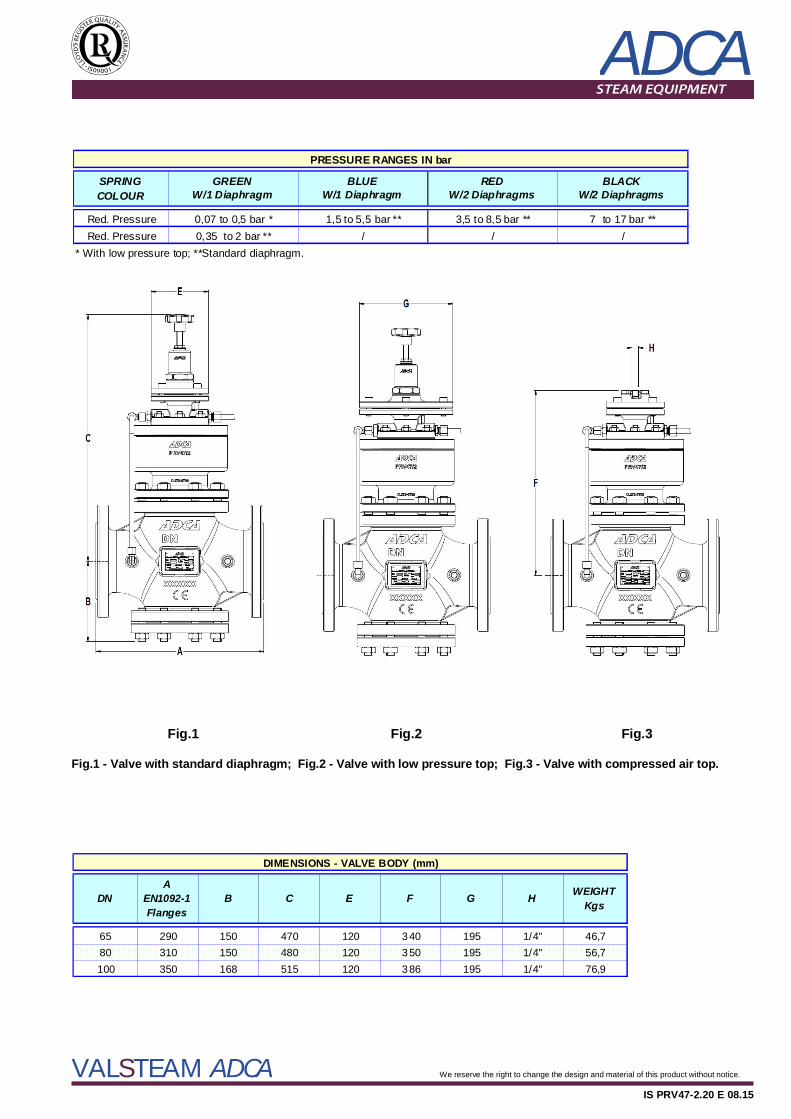
Fig.1 Fig.2 Fig.3 Fig.1 - Valve with standard diaphragm; Fig.2 - Valve with low pressure top; Fig.3 - Valve with compressed air top.
65 290 150 470 120 340 195 1/4" 46,780 310 150 480 120 350 195 1/4" 56,7100 350 168 515 120 386 195 1/4" 76,9
DIMENSIONS - VALVE BODY (mm)
H WEIGHT KgsEDN
A EN1092-1 Flanges
B C F G
SPRING COLOUR
Red. PressureRed. Pressure / /
* With low pressure top; **Standard diaphragm.
PRESSURE RANGES IN bar
BLACK W/2 Diaphragms
RED W/2 Diaphragms
3,5 to 8,5 bar ** 7 to 17 bar **
BLUE W/1 Diaphragm
1,5 to 5,5 bar **/
GREEN W/1 Diaphragm
0,07 to 0,5 bar *0,35 to 2 bar **
ADCA
VALSTEAM ADCA We reserve the right to change the design and material of this product without notice.
IS PRV47-2.20 E 08.15
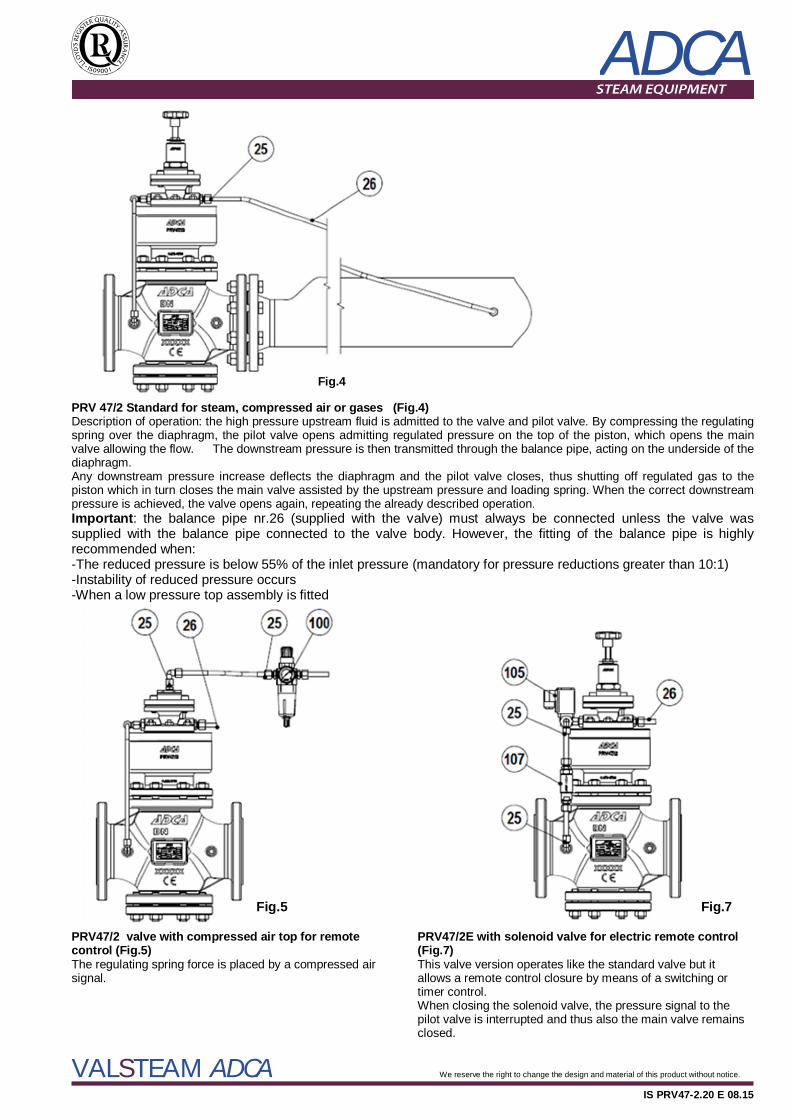
Fig.4 PRV 47/2 Standard for steam, compressed air or gases (Fig.4) Description of operation: the high pressure upstream fluid is admitted to the valve and pilot valve. By compressing the regulating spring over the diaphragm, the pilot valve opens admitting regulated pressure on the top of the piston, which opens the main valve allowing the flow. The downstream pressure is then transmitted through the balance pipe, acting on the underside of the diaphragm. Any downstream pressure increase deflects the diaphragm and the pilot valve closes, thus shutting off regulated gas to the piston which in turn closes the main valve assisted by the upstream pressure and loading spring. When the correct downstream pressure is achieved, the valve opens again, repeating the already described operation. Important: the balance pipe nr.26 (supplied with the valve) must always be connected unless the valve was supplied with the balance pipe connected to the valve body. However, the fitting of the balance pipe is highly recommended when: -The reduced pressure is below 55% of the inlet pressure (mandatory for pressure reductions greater than 10:1) -Instability of reduced pressure occurs -When a low pressure top assembly is fitted Fig.5 Fig.7 PRV47/2 valve with compressed air top for remote control (Fig.5) The regulating spring force is placed by a compressed air signal.
PRV47/2E with solenoid valve for electric remote control (Fig.7) This valve version operates like the standard valve but it allows a remote control closure by means of a switching or timer control. When closing the solenoid valve, the pressure signal to the pilot valve is interrupted and thus also the main valve remains closed.
ADCA
VALSTEAM ADCA We reserve the right to change the design and material of this product without notice.
IS PRV47-2.20 E 08.15
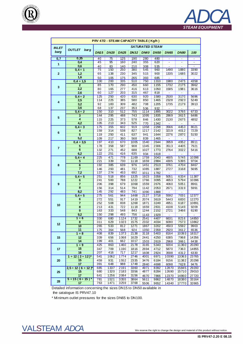
DN15 DN20 DN25 DN32 DN40 DN50 DN65 DN80 100
0,7 0,35 40 75 125 190 280 480 - - -0,4 45 95 160 240 355 620 - - -0,6 40 83 140 210 308 535 - - -
0,4 ÷ 1 75 150 250 380 545 960 1490 1880 33901,2 65 138 230 345 515 900 1335 1685 30221,6 50 105 175 265 393 685 - - -
0,4 ÷ 1,5 100 200 335 510 750 1310 1980 2475 43582 85 170 290 450 660 1155 1732 2175 3962
2,2 80 165 277 416 613 1050 1585 1981 36162,6 60 127 203 315 467 818 - - -
0,4 ÷ 2 125 250 420 630 920 1580 2530 3170 56962,5 114 225 385 580 850 1465 2328 2923 52493,2 92 183 309 482 708 1205 1735 2179 39133,6 68 137 237 353 536 932 - - -
0,4 ÷ 2 150 310 512 755 1114 1895 3022 3765 67333 144 295 488 743 1095 1835 2869 3615 64864 115 225 373 578 846 1430 2130 2675 4852
4,2 105 213 343 525 770 1342 - - -0,4 ÷ 3 175 355 602 919 1358 2298 3566 4453 8021
4 159 314 538 827 1217 2142 3219 4012 72295 119 250 411 637 941 1644 2276 2870 5150
5,2 109 217 360 568 839 1465 - - -0,4 ÷ 3,5 197 410 670 1005 1540 2644 3959 4952 8911
5 178 358 587 908 1345 2306 3513 4405 79216 132 271 452 688 1027 1773 2764 3022 5416
6,2 122 251 416 635 934 1618 - - -0,4 ÷ 4 225 471 778 1169 1759 3043 4605 5745 10398
5 221 339 730 1118 1659 2884 4305 5395 97046 192 385 639 976 1451 2513 3761 4704 84677 146 293 481 732 1085 1887 2727 3168 5695
7,2 137 274 453 692 1011 1782 - - -0,4 ÷ 5 251 518 856 1325 1923 3358 5051 6334 11387
6 241 500 788 1222 1766 3095 4653 5794 103967 206 398 679 1068 1559 2676 4060 5051 89618 156 314 514 794 1142 2053 2671 3319 5991
8,2 145 292 483 741 1090 1888 - -0,4 ÷ 5 275 561 944 1468 2127 3718 5592 7031 12377
6 272 551 917 1419 2074 3619 5443 6830 122707 252 508 838 1268 1871 3249 4951 6187 108918 213 431 722 1118 1659 2831 4108 5149 92099 163 333 548 843 1244 2152 2721 3466 6190
9,2 150 298 493 756 1143 1929 - - -1 ÷ 6 330 680 1124 1732 2541 4407 6631 8216 14850
8 311 629 1023 1575 2332 4034 6090 7573 1386210 265 533 812 1271 1867 3202 4503 5592 990311 175 364 568 924 1350 2359 2920 3612 6536
1 ÷ 8 408 839 1373 2138 3118 5403 8164 10393 1831712 339 656 1068 1629 2441 4250 6385 7968 1435614 199 401 662 1017 1503 2619 2968 3661 6438
1 ÷ 9 425 863 1460 2178 3165 5343 9204 11360 2029015 347 709 1190 1816 2694 4712 5870 7363 1485516 207 416 717 1217 1608 2824 3598 4312 6330
1 ÷ 12 ( 2 ÷ 12 )* 541 1062 1774 2746 4001 6971 10390 13363 2376515 459 931 1552 2335 3476 6184 9156 11382 2029817 391 648 988 1748 2840 4698 6098 7628 9476
2,5 ÷ 12 ( 6 ÷ 12 )* 685 1337 2191 3360 4971 8392 12870 15845 2920015 680 1320 2183 3356 4877 8284 12690 15710 2901017 641 1256 2084 3156 4670 7866 12370 14860 27720
5 ÷ 15 ( 6 ÷ 15 ) * 781 1521 3355 3864 5611 9862 14870 18380 3316417 763 1471 3259 3768 5506 9652 14340 17770 32665
Detailed information concerning the sizes DN15 to DN50 available in the catalogue IS PRV47.10 * Minimum outlet pressures for the sizes DN65 to DN100.
9
10
1
2
3
4
5
6
7
8
SATURATED STEAM INLET barg OUTLET barg
PRV 47/2 - STEAM CAPACITY TABLE ( Kg/h )
25
28
12
15
17
20
ADCA
VALSTEAM ADCA We reserve the right to change the design and material of this product without notice.
IS PRV47-2.20 E 08.15
V47 S. 1 1. A 65V47
V47G
(1)I
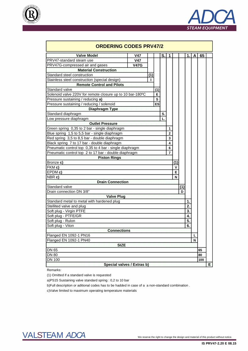
(1)ES
ES
S.L.
123467
(1)VEN
(1)D
1.2.3.4.5.6.
LN
6580100
ERemarks:(1) Omitted if a standard valve is requesteda)PS15 Sustaining valve standard spring : 0,2 to 10 barb)Full description or aditional codes has to be hadded in case of a a non-standard combination .c)Valve limited to maximum operating temperature materials
Blue spring 1,5 to 5,5 bar - single diaphragm
Valve PlugStandard metal to metal with hardened plug
Standard valve
Soft plug - Rulon
Drain Connection
EPDM c)
Stellited valve and plug
DN 65
ConnectionsFlanged EN 1092-1 PN16
Outlet Pressure
PRV47G-compressed air and gases
SIZE
Soft plug - Virgin PTFESoft plug - PTFE/GR
Standard steel construction
Soft plug - Viton
Stainless steel construction (special design)Remote Control and Pilots
Green spring 0,35 to 2 bar - single diaphragm
ORDERING CODES PRV47/2
Black spring 7 to 17 bar - double diaphragm
Diaphragm TypeStandard diaphragmLow pressure diaphragm
Red spring 3,5 to 8,5 bar - double diaphragm
Standard valve
DN 80
Pressure sustaining / reducing / solenoid
Valve Model
NBR c)
PRV47-standard steam use
Solenoid valve 220V for remote closure up to 10 bar-180ºCPressure sustaining / reducing a)
Pneumatic control top 0,35 to 4 bar - single diaphragm
Material Construction
Pneumatic control top 2 to 17 bar - double diaphragm
Drain connection DN 3/8"
Piston RingsBronze c)FKM c)
DN 100Special valves / Extras b)
Flanged EN 1092-1 PN40