Embed Size (px)
DESCRIPTION
ADP
Citation preview
» » » P a g e | 1
««« Aircraft Design Project – II »»»
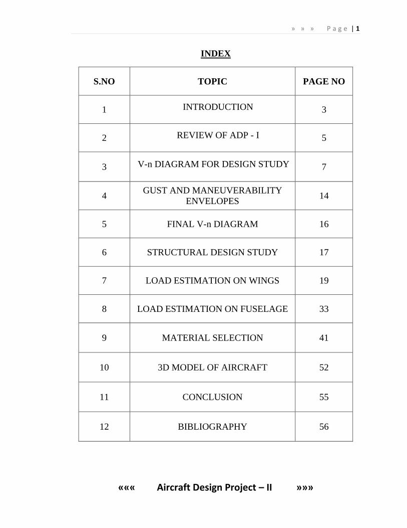
INDEX
S.NO TOPIC PAGE NO
1 INTRODUCTION 3
2 REVIEW OF ADP - I 5
3 V-n DIAGRAM FOR DESIGN STUDY 7
4 GUST AND MANEUVERABILITY
ENVELOPES 14
5 FINAL V-n DIAGRAM 16
6 STRUCTURAL DESIGN STUDY 17
7 LOAD ESTIMATION ON WINGS 19
8 LOAD ESTIMATION ON FUSELAGE 33
9 MATERIAL SELECTION 41
10 3D MODEL OF AIRCRAFT 52
11 CONCLUSION 55
12 BIBLIOGRAPHY 56
» » » P a g e | 2
««« Aircraft Design Project – II »»»
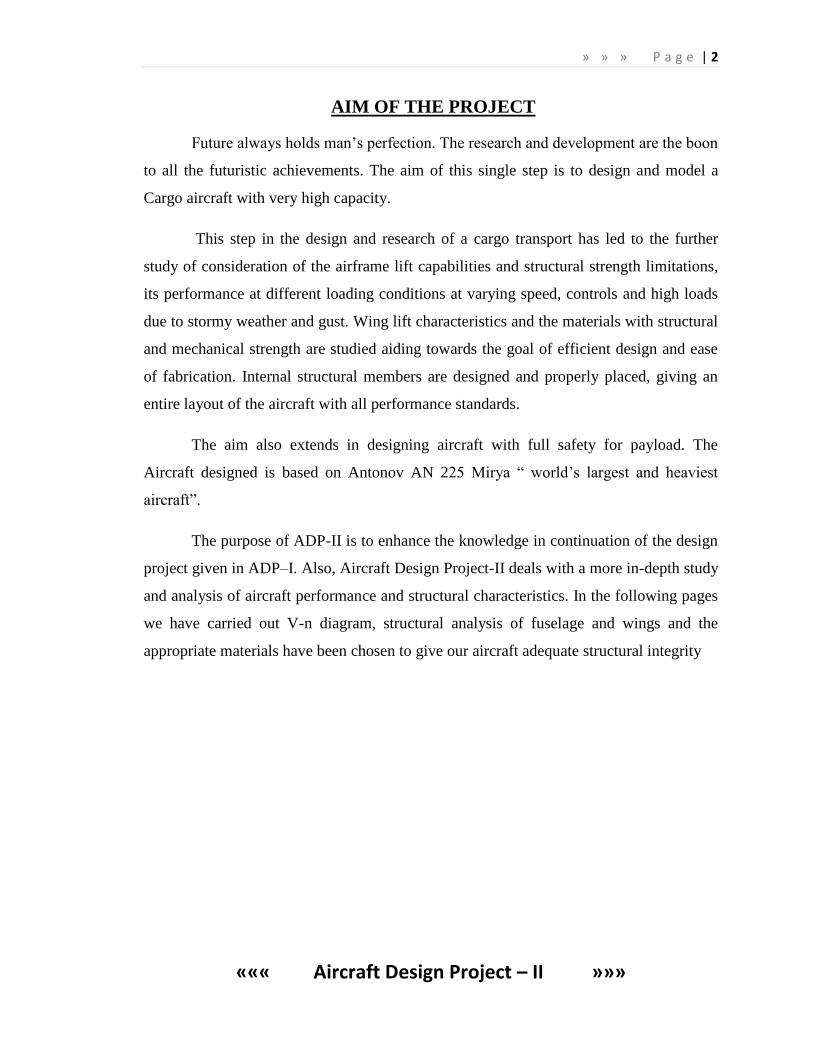
AIM OF THE PROJECT
Future always holds man’s perfection. The research and development are the boon
to all the futuristic achievements. The aim of this single step is to design and model a
Cargo aircraft with very high capacity.
This step in the design and research of a cargo transport has led to the further
study of consideration of the airframe lift capabilities and structural strength limitations,
its performance at different loading conditions at varying speed, controls and high loads
due to stormy weather and gust. Wing lift characteristics and the materials with structural
and mechanical strength are studied aiding towards the goal of efficient design and ease
of fabrication. Internal structural members are designed and properly placed, giving an
entire layout of the aircraft with all performance standards.
The aim also extends in designing aircraft with full safety for payload. The
Aircraft designed is based on Antonov AN 225 Mirya ― world’s largest and heaviest
aircraft‖.
The purpose of ADP-II is to enhance the knowledge in continuation of the design
project given in ADP–I. Also, Aircraft Design Project-II deals with a more in-depth study
and analysis of aircraft performance and structural characteristics. In the following pages
we have carried out V-n diagram, structural analysis of fuselage and wings and the
appropriate materials have been chosen to give our aircraft adequate structural integrity
» » » P a g e | 3
««« Aircraft Design Project – II »»»
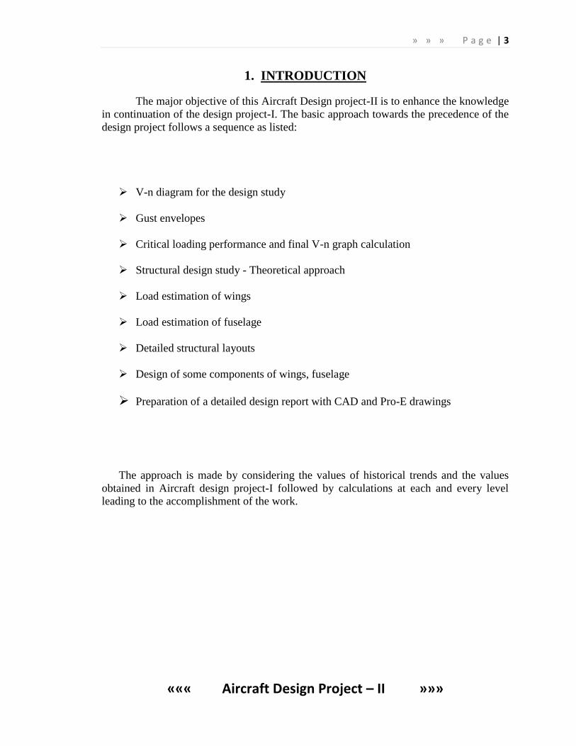
1. INTRODUCTION
The major objective of this Aircraft Design project-II is to enhance the knowledge
in continuation of the design project-I. The basic approach towards the precedence of the
design project follows a sequence as listed:
V-n diagram for the design study
Gust envelopes
Critical loading performance and final V-n graph calculation
Structural design study - Theoretical approach
Load estimation of wings
Load estimation of fuselage
Detailed structural layouts
Design of some components of wings, fuselage
Preparation of a detailed design report with CAD and Pro-E drawings
The approach is made by considering the values of historical trends and the values
obtained in Aircraft design project-I followed by calculations at each and every level
leading to the accomplishment of the work.
» » » P a g e | 4
««« Aircraft Design Project – II »»»
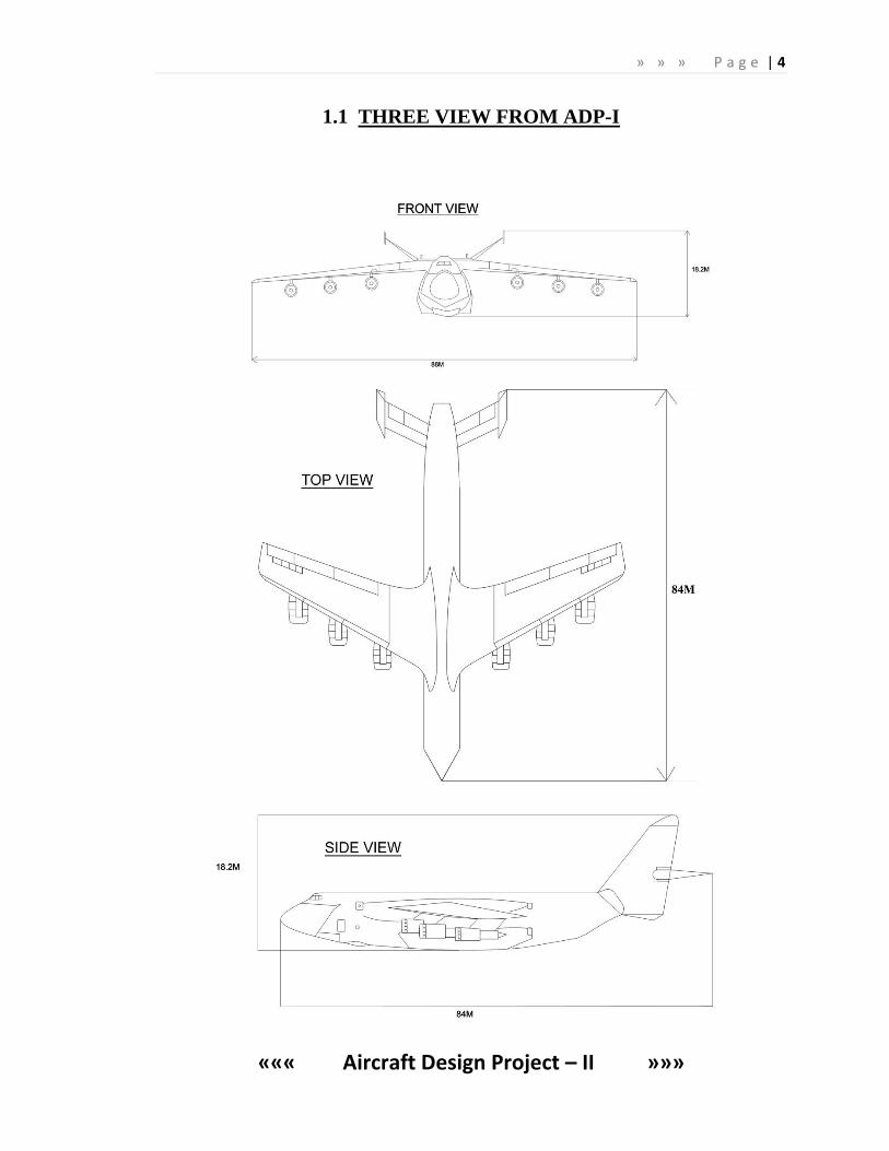
1.1 THREE VIEW FROM ADP-I
» » » P a g e | 5
««« Aircraft Design Project – II »»»
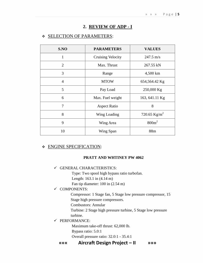
2. REVIEW OF ADP - I
SELECTION OF PARAMETERS:
S.NO PARAMETERS VALUES
1 Cruising Velocity 247.5 m/s
2 Max. Thrust 267.55 kN
3 Range 4,500 km
4 MTOW 654,564.42 Kg
5 Pay Load 250,000 Kg
6 Max. Fuel weight 163, 641.11 Kg
7 Aspect Ratio 8
8 Wing Loading 720.65 Kg/m2
9 Wing Area 800m2
10 Wing Span 88m
ENGINE SPECIFICATION:
PRATT AND WHTINEY PW 4062
GENERAL CHARACTERISTICS:
Type: Two spool high bypass ratio turbofan.
Length: 163.1 in (4.14 m)
Fan tip diameter: 100 in (2.54 m)
COMPONENTS:
Compressor: 1 Stage fan, 5 Stage low pressure compressor, 15
Stage high pressure compressors.
Combustors: Annular
Turbine: 2 Stage high pressure turbine, 5 Stage low pressure
turbine.
PERFORMANCE:
Maximum take-off thrust: 62,000 lb.
Bypass ratio: 5.0:1
Overall pressure ratio: 32.0:1 - 35.4:1
» » » P a g e | 6
««« Aircraft Design Project – II »»»
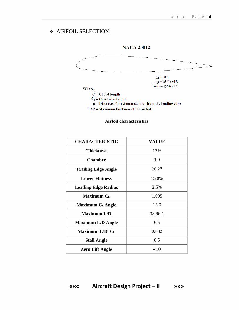
AIRFOIL SELECTION:
Airfoil characteristics
CHARACTERISTIC VALUE
Thickness 12%
Chamber 1.9
Trailing Edge Angle 28.2°
Lower Flatness 55.0%
Leading Edge Radius 2.5%
Maximum CL 1.095
Maximum CL Angle 15.0
Maximum L/D 38.96:1
Maximum L/D Angle 6.5
Maximum L/D CL 0.882
Stall Angle 8.5
Zero Lift Angle -1.0
» » » P a g e | 7
««« Aircraft Design Project – II »»»
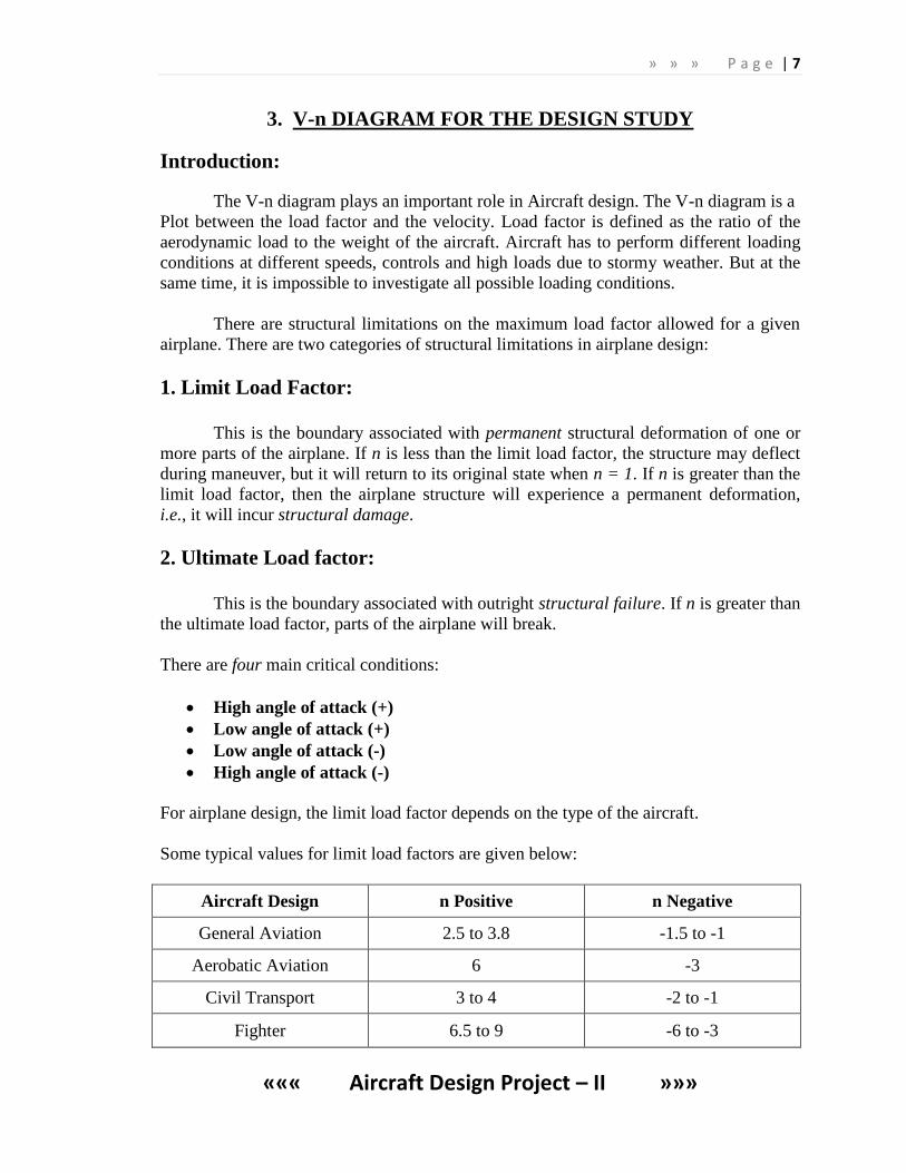
3. V-n DIAGRAM FOR THE DESIGN STUDY
Introduction:
The V-n diagram plays an important role in Aircraft design. The V-n diagram is a
Plot between the load factor and the velocity. Load factor is defined as the ratio of the
aerodynamic load to the weight of the aircraft. Aircraft has to perform different loading
conditions at different speeds, controls and high loads due to stormy weather. But at the
same time, it is impossible to investigate all possible loading conditions.
There are structural limitations on the maximum load factor allowed for a given
airplane. There are two categories of structural limitations in airplane design:
1. Limit Load Factor:
This is the boundary associated with permanent structural deformation of one or
more parts of the airplane. If n is less than the limit load factor, the structure may deflect
during maneuver, but it will return to its original state when n = 1. If n is greater than the
limit load factor, then the airplane structure will experience a permanent deformation,
i.e., it will incur structural damage.
2. Ultimate Load factor:
This is the boundary associated with outright structural failure. If n is greater than
the ultimate load factor, parts of the airplane will break.
There are four main critical conditions:
High angle of attack (+)
Low angle of attack (+)
Low angle of attack (-)
High angle of attack (-)
For airplane design, the limit load factor depends on the type of the aircraft.
Some typical values for limit load factors are given below:
Aircraft Design n Positive n Negative
General Aviation 2.5 to 3.8 -1.5 to -1
Aerobatic Aviation 6 -3
Civil Transport 3 to 4 -2 to -1
Fighter 6.5 to 9 -6 to -3
» » » P a g e | 8
««« Aircraft Design Project – II »»»
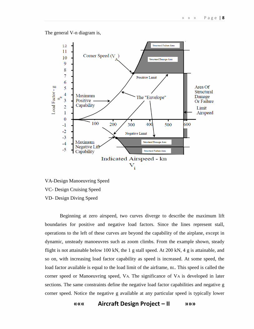
The general V-n diagram is,
VA-Design Manoeuvring Speed
VC- Design Cruising Speed
VD- Design Diving Speed
Beginning at zero airspeed, two curves diverge to describe the maximum lift
boundaries for positive and negative load factors. Since the lines represent stall,
operations to the left of these curves are beyond the capability of the airplane, except in
dynamic, unsteady manoeuvres such as zoom climbs. From the example shown, steady
flight is not attainable below 100 kN, the 1 g stall speed. At 200 kN, 4 g is attainable, and
so on, with increasing load factor capability as speed is increased. At some speed, the
load factor available is equal to the load limit of the airframe, nL. This speed is called the
corner speed or Manoeuvring speed, VA. The significance of VA is developed in later
sections. The same constraints define the negative load factor capabilities and negative g
corner speed. Notice the negative g available at any particular speed is typically lower
» » » P a g e | 9
««« Aircraft Design Project – II »»»
than the positive g available, due to the wing camber and control power effects. The
envelope is bounded on the right for all load factors by the limit airspeed, VL.
The lift boundary of the V-n diagram is the primary focus of flight test
documentation. The airplane is able to develop n limit at all speeds above VA, though it
may be difficult to verify near VL due to the deceleration experienced while pulling to n
limit. For airspeeds above VA, calculations of instantaneous turn performance parameters
can be made without documentation, based on the constant n limit out to VL. Flight tests
are required, however, to document the boundary imposed by the lift limit, where the
maximum load factor is diminished. The measure of instantaneous maneuverability is not
only a high n limit, but also a low VA.
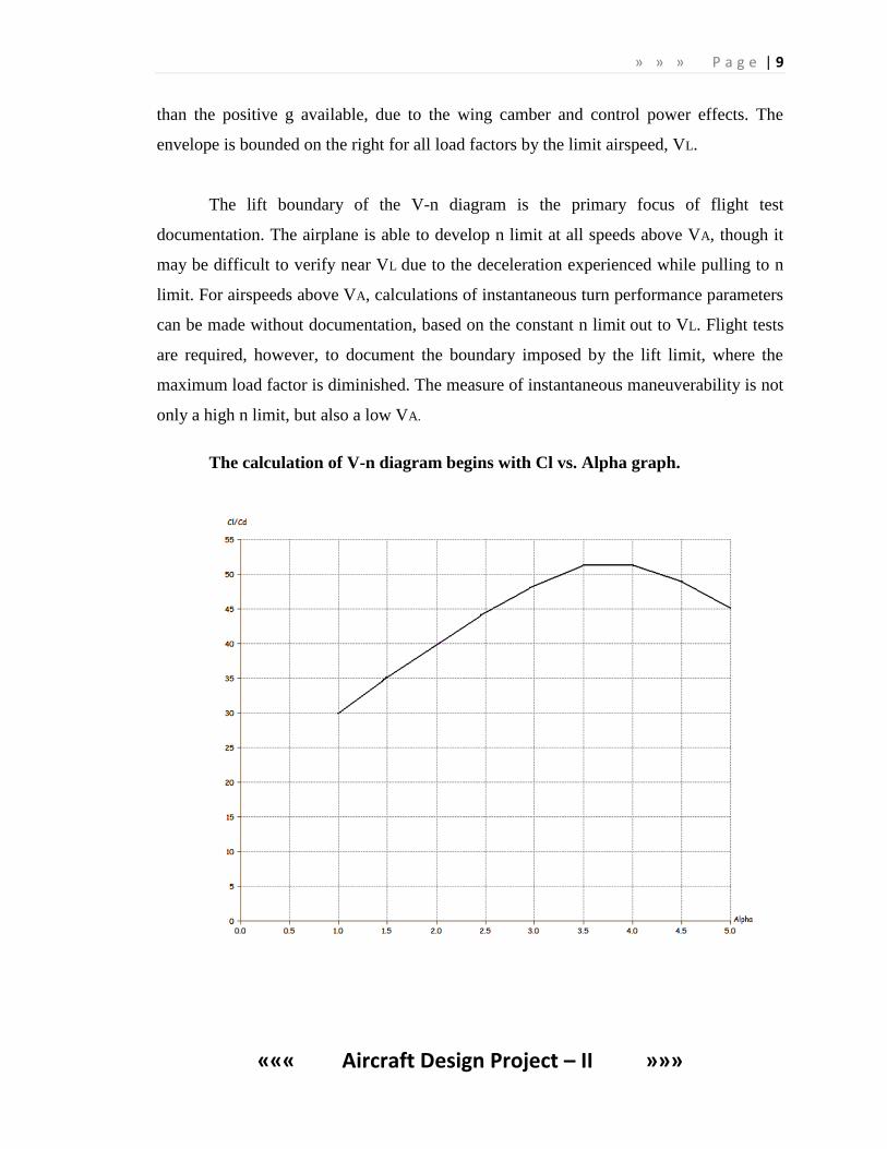
The calculation of V-n diagram begins with Cl vs. Alpha graph.
» » » P a g e | 10
««« Aircraft Design Project – II »»»
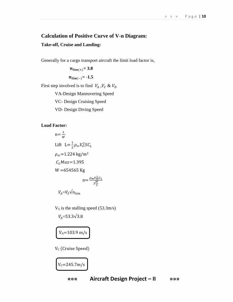
Calculation of Positive Curve of V-n Diagram:
Take-off, Cruise and Landing:
Generally for a cargo transport aircraft the limit load factor is,
= 3.8
= -1.5
First step involved is to find , &
VA-Design Maneuvering Speed
VC- Design Cruising Speed
VD- Design Diving Speed
Load Factor:
n=
Lift L=
=1.224 kg/m3
=1.395
W =654565 Kg
n=
=
VS is the stalling speed (53.3m/s)
=53.3
VA=103.9 m/s
VC (Cruise Speed)
VC=245.7m/s
» » » P a g e | 11
««« Aircraft Design Project – II »»»
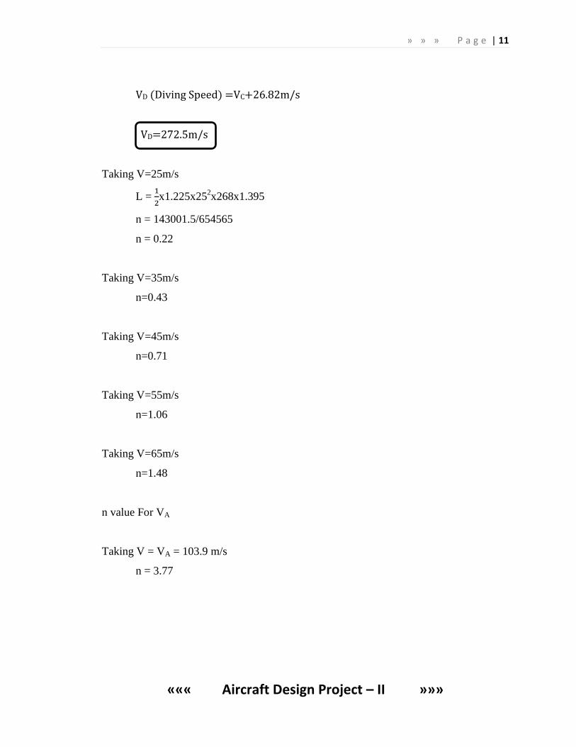
VD (Diving Speed) =VC+26.82m/s
VD=272.5m/s
Taking V=25m/s
L =
x1.225x25
2x268x1.395
n = 143001.5/654565
n = 0.22
Taking V=35m/s
n=0.43
Taking V=45m/s
n=0.71
Taking V=55m/s
n=1.06
Taking V=65m/s
n=1.48
n value For VA
Taking V = VA = 103.9 m/s
n = 3.77
» » » P a g e | 12
««« Aircraft Design Project – II »»»
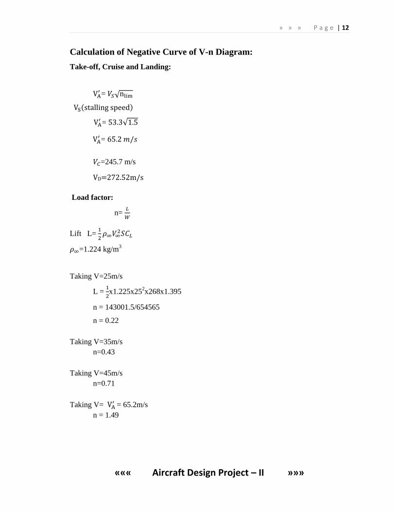
Calculation of Negative Curve of V-n Diagram:
Take-off, Cruise and Landing:
=
=
=
=245.7 m/s
VD=272.52m/s
Load factor:
n=
Lift L=
=1.224 kg/m3
Taking V=25m/s
L =
x1.225x25
2x268x1.395
n = 143001.5/654565
n = 0.22
Taking V=35m/s
n=0.43
Taking V=45m/s
n=0.71
Taking V=
= 65.2m/s
n = 1.49
» » » P a g e | 13
««« Aircraft Design Project – II »»»
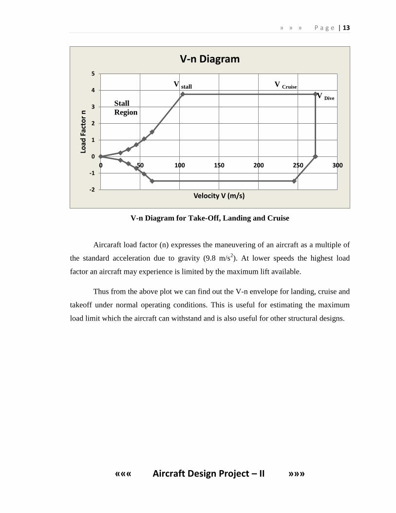
V-n Diagram for Take-Off, Landing and Cruise
Aircaraft load factor (n) expresses the maneuvering of an aircraft as a multiple of
the standard acceleration due to gravity (9.8 m/s2). At lower speeds the highest load
factor an aircraft may experience is limited by the maximum lift available.
Thus from the above plot we can find out the V-n envelope for landing, cruise and
takeoff under normal operating conditions. This is useful for estimating the maximum
load limit which the aircraft can withstand and is also useful for other structural designs.
-2
-1
0
1
2
3
4
5
0 50 100 150 200 250 300
Load
Fac
tor
n
Velocity V (m/s)
V-n Diagram
V stall V Cruise
V Dive
Stall
Region
» » » P a g e | 14
««« Aircraft Design Project – II »»»
4. GUST ENVELOPE:
Vcruise = 245.7m/s
Vdive = 272.5m/s
Vg=Maximum speed in turbulence
⁄
Gust Velocity, V=KVde
Where,
K=Gust Elevation Factor
K (Subsonic) =
=0.79
MAC=3m
⁄
= 47.76
Vg =160m/s
Vd =272.5.55m/s
Vc =245.7m/s
Calculation of Positive Curve of Gust V-n Diagram:
For Stall:
=0.58
For Cruise:
=1.03
For Dive:
=0.76
Calculation of Negative Curve of Gust V-n Diagram:
For Stall:
=0.37
For Cruise:
=0.66
» » » P a g e | 15
««« Aircraft Design Project – II »»»
For Dive:
=0.48
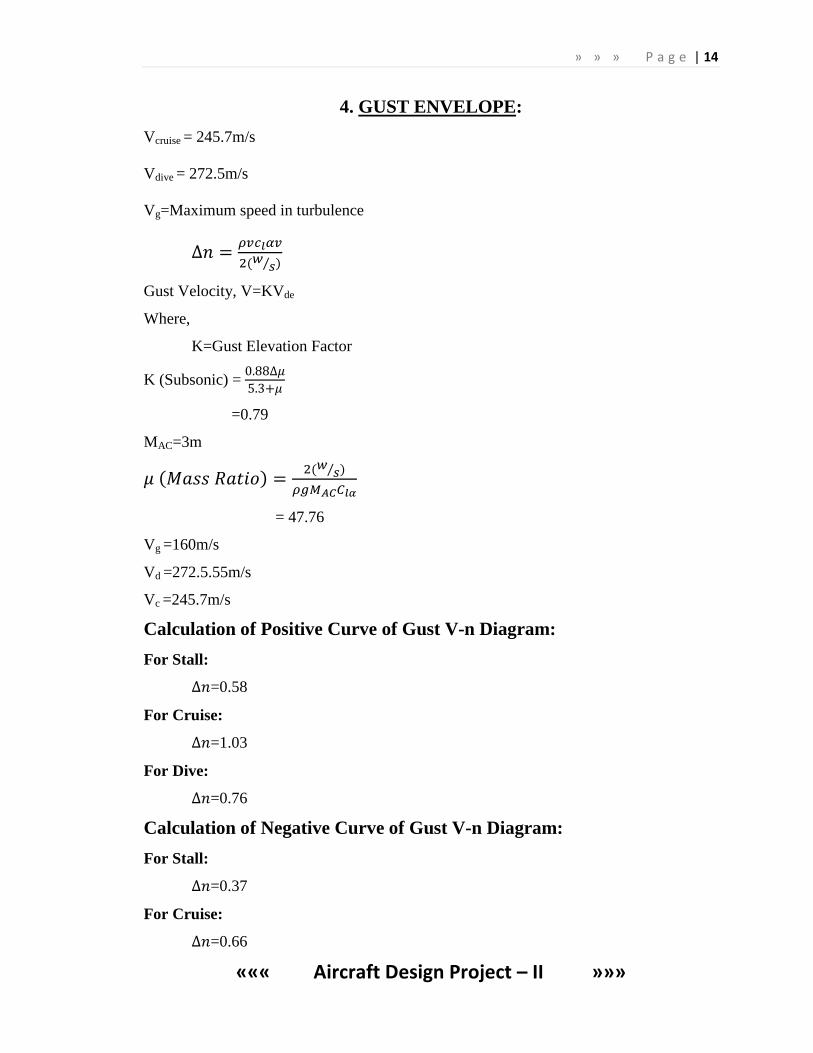
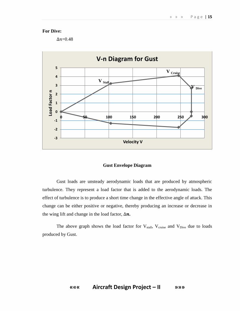
Gust Envelope Diagram
Gust loads are unsteady aerodynamic loads that are produced by atmospheric
turbulence. They represent a load factor that is added to the aerodynamic loads. The
effect of turbulence is to produce a short time change in the effective angle of attack. This
change can be either positive or negative, thereby producing an increase or decrease in
the wing lift and change in the load factor, .
The above graph shows the load factor for Vstall, Vcruise and VDive due to loads
produced by Gust.
-3
-2
-1
0
1
2
3
4
5
0 50 100 150 200 250 300
Load
Fac
tor
n
Velocity V
V-n Diagram for Gust
V Stall
V Cruise
V Dive
» » » P a g e | 16
««« Aircraft Design Project – II »»»
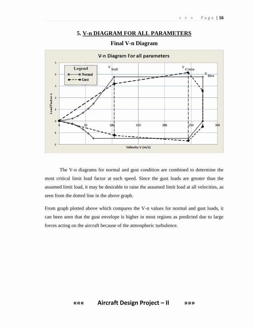
5. V-n DIAGRAM FOR ALL PARAMETERS
Final V-n Diagram
The V-n diagrams for normal and gust condition are combined to determine the
most critical limit load factor at each speed. Since the gust loads are greater than the
assumed limit load, it may be desirable to raise the assumed limit load at all velocities, as
seen from the dotted line in the above graph.
From graph plotted above which compares the V-n values for normal and gust loads, it
can been seen that the gust envelope is higher in most regions as predicted due to large
forces acting on the aircraft because of the atmospheric turbulence.
» » » P a g e | 17
««« Aircraft Design Project – II »»»
6. STRUCTURAL DESIGN STUDY
6.1 Introduction
Aircraft loads are those forces and loadings applied to the airplanes structural
components to establish the strength level of the complete airplane. These loadings may
be caused by air pressure, inertia forces, or ground reactions during landing. In more
specialized cases, design loadings may be imposed during other operations such as
catapulted take-offs, arrested landings, or landings in water.
The determination of design loads involves a study of the air pressures and inertia
forces during certain prescribed maneuvers, either in the air or on the ground. Since the
primary objective is an airplane with a satisfactory strength level, the means by which
this result is obtained is sometimes unimportant. Some of the prescribed maneuvers are
therefore arbitrary and empirical which is indicated by a careful examination of some of
the criteria.
Important consideration in determining the extent of the load analysis is the
amount of structural weight involved. A fairly detailed analysis may be necessary when
computing operating loads on such items as movable surfaces, doors, landing gears, etc.
proper operation of the system requires an accurate prediction of the loads.
Aircraft loads is the science of determining the loads that an aircraft structure
must be designed to withstand. A large part of the forces that make up design loads are
the forces resulting from the flow of air about the airplane’s surfaces- the same forces
that enable flight and control of the aircraft.
6.2 Load factors
In normal straight and level flight the wing lift supports the weight of the airplane.
During maneuvers or flight through turbulent (gusty) air, however, additional loads are
imposed which will increase or decrease the net loads on the airplane structure. The
amount of additional loads depends on the severity of the maneuvers or the turbulence,
and its magnitude is measured in terms of load factor.
The maximum maneuvering load factor to which an airplane is designed depends
on its intended usage. Fighters, which are expected to execute violent maneuvers, are
designed to withstand loads commensurate with the accelerations a pilot can physically
withstand. Long range, heavily loaded bombers, on the other hand, are designed to low
load factors and must be handled accordingly.
For a typical two spar layout, the ribs are usually formed in three parts from sheet
metal by the use of presses and dies. Flanges are incorporated around the edges so that
» » » P a g e | 18
««« Aircraft Design Project – II »»»
they can be riveted to the skin and the spar webs Cut-outs are necessary around the edges
to allow for the stringers to pass through Lightening holes are usually cut into the rib
bodies to reduce the rib weight and also allow for passage of control runs fuel electrics
etc.
6.3 Structural design criteria
The structural criteria define the types of maneuvers, speed, useful loads, and
gross weights which are to be considered for structural design analysis. These are items
which are under the control of the airplane operator. In addition, the structural criteria
must consider such items as inadvertent maneuvers, effects of turbulent air, and severity
of ground contact during landing. The basic structural design criteria, from which the
loadings are determined, are based largely on the type of the airplane and its intended
use.
» » » P a g e | 19
««« Aircraft Design Project – II »»»
7. LOAD ESTIMATION OF WINGS
7.1 Wing Geometry & Lift Distribution:
An elliptic lift distribution causes the downwash across the span to be a constant.
As a result the induced drag is a minimum when compared to a planar wing of equal
span, total lift and velocity. The elliptic loading can be achieved by use of an elliptic plan
form with no wing twist. The same distribution can also be achieved by adding the
appropriate twist to the wing, altering the local angle of attack for a given chord of the
wing. For the elliptic plan form wing with no twist, since the absolute angle of attack and
downwash angle are span wise constant, the effective angle of attack is also constant.
The defining characteristics of an elliptical loading are:
For a planar wing, the induced drag is at a minimum, for a fixed span, total lift,
and equivalent velocity.
The downwash across the span is constant.
The elliptic lift distribution occurs naturally on a planar wing with an elliptical
plan form. The angle of attack for all aerofoil sections of the wing are the same
for the untwisted (planar) wing.
The effective angle of attack, , and the local lift coefficient, , are constant
along the span as a result of the absolute angle of attack, , and the downwash
angle, , are constant along the span.
Elliptic Distribution Restoration
Elliptically loaded wing has the lowest possible induced drag for a given wing
aspect ratio, and lift coefficient. Aerodynamic designers strive to achieve an elliptic lift
distribution to achieve this desired effect. They can do this by adjusting the chord
distribution, the twist distribution, and/or the angle of zero lift distribution.
» » » P a g e | 20
««« Aircraft Design Project – II »»»
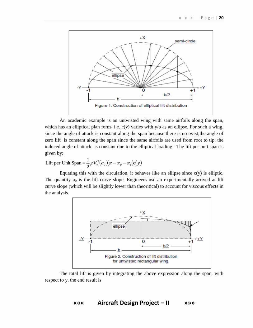
An academic example is an untwisted wing with same airfoils along the span,
which has an elliptical plan form- i.e. c(y) varies with y/b as an ellipse. For such a wing,
since the angle of attack is constant along the span because there is no twist;the angle of
zero lift is constant along the span since the same airfoils are used from root to tip; the
induced angle of attack is constant due to the elliptical loading. The lift per unit span is
given by:
ycaV i 00
2
2
1 Span per Unit Lift
Equating this with the circulation, it behaves like an ellipse since c(y) is elliptic.
The quantity a0 is the lift curve slope. Engineers use an experimentally arrived at lift
curve slope (which will be slightly lower than theoritical) to account for viscous effects in
the analysis.
The total lift is given by integrating the above expression along the span, with
respect to y. the end result is
» » » P a g e | 21
««« Aircraft Design Project – II »»»
SaVdyycaV i
b
b
i
00
2
00
2
2
1)(
2
1 LLift
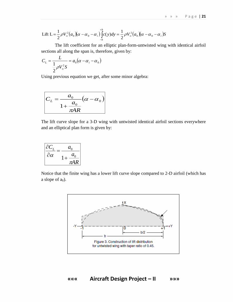
The lift coefficient for an elliptic plan-form-untwisted wing with identical airfoil
sections all along the span is, therefore, given by:
002
2
1
iL a
SV
LC
Using previous equation we get, after some minor algebra:
00
0
1
AR
a
aCL
The lift curve slope for a 3-D wing with untwisted identical airfoil sections everywhere
and an elliptical plan form is given by:
AR
a
aCL
0
0
1
Notice that the finite wing has a lower lift curve slope compared to 2-D airfoil (which has
a slope of a0).
» » » P a g e | 22
««« Aircraft Design Project – II »»»
The smaller the aspect ratio, the lower the lift curve slope. For more general wings, the
drag coefficient will be higher than that given by, and the lift curve slope will be lower
than that given by equation.
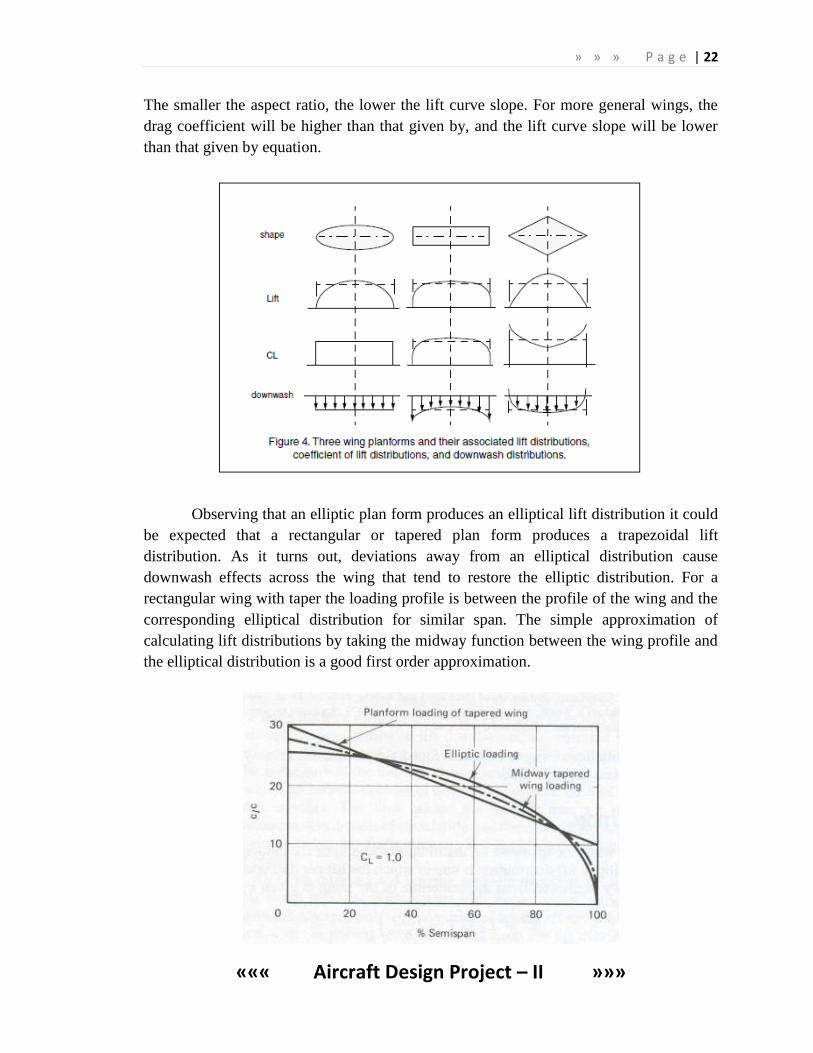
Observing that an elliptic plan form produces an elliptical lift distribution it could
be expected that a rectangular or tapered plan form produces a trapezoidal lift
distribution. As it turns out, deviations away from an elliptical distribution cause
downwash effects across the wing that tend to restore the elliptic distribution. For a
rectangular wing with taper the loading profile is between the profile of the wing and the
corresponding elliptical distribution for similar span. The simple approximation of
calculating lift distributions by taking the midway function between the wing profile and
the elliptical distribution is a good first order approximation.
» » » P a g e | 23
««« Aircraft Design Project – II »»»
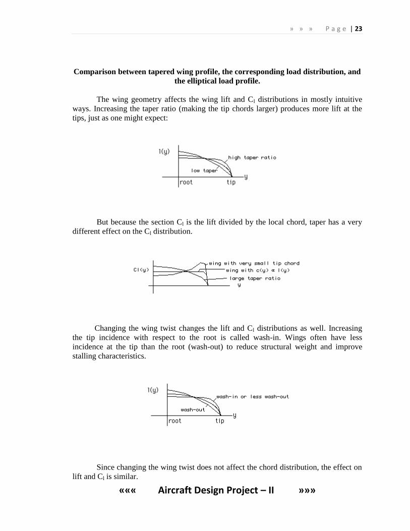
Comparison between tapered wing profile, the corresponding load distribution, and
the elliptical load profile.
The wing geometry affects the wing lift and Cl distributions in mostly intuitive
ways. Increasing the taper ratio (making the tip chords larger) produces more lift at the
tips, just as one might expect:
But because the section Cl is the lift divided by the local chord, taper has a very
different effect on the Cl distribution.
Changing the wing twist changes the lift and Cl distributions as well. Increasing
the tip incidence with respect to the root is called wash-in. Wings often have less
incidence at the tip than the root (wash-out) to reduce structural weight and improve
stalling characteristics.
Since changing the wing twist does not affect the chord distribution, the effect on
lift and Cl is similar.
» » » P a g e | 24
««« Aircraft Design Project – II »»»
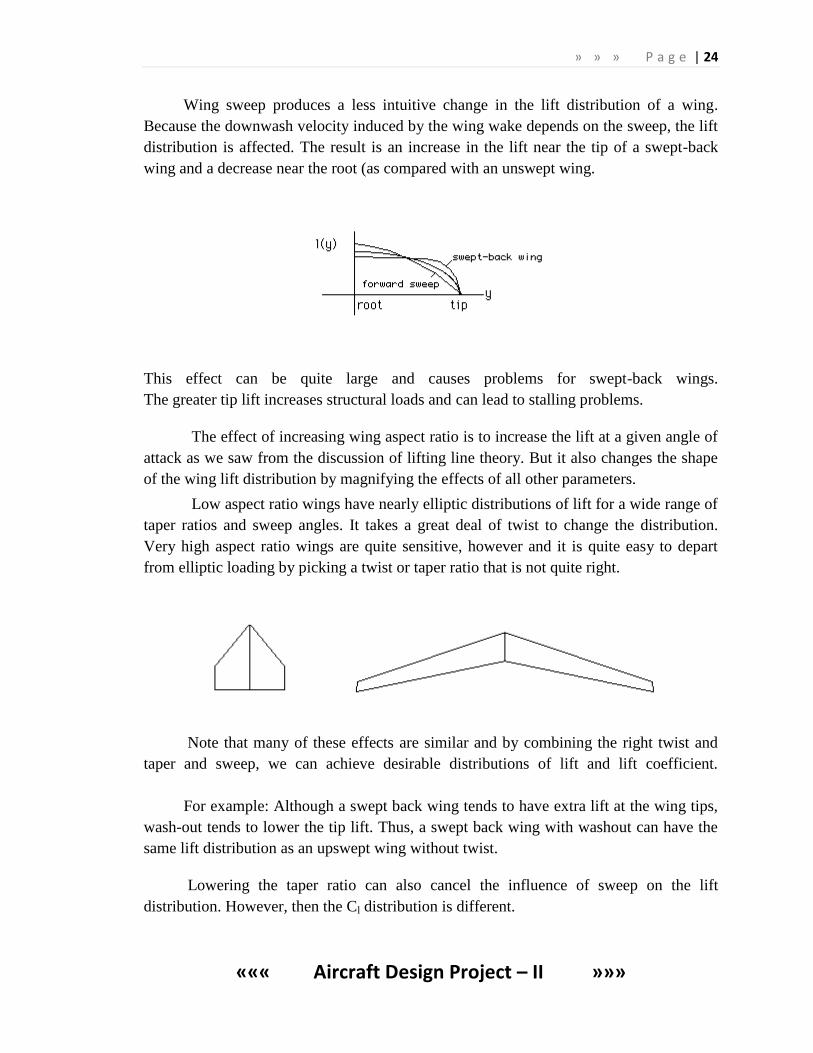
Wing sweep produces a less intuitive change in the lift distribution of a wing.
Because the downwash velocity induced by the wing wake depends on the sweep, the lift
distribution is affected. The result is an increase in the lift near the tip of a swept-back
wing and a decrease near the root (as compared with an unswept wing.
This effect can be quite large and causes problems for swept-back wings.
The greater tip lift increases structural loads and can lead to stalling problems.
The effect of increasing wing aspect ratio is to increase the lift at a given angle of
attack as we saw from the discussion of lifting line theory. But it also changes the shape
of the wing lift distribution by magnifying the effects of all other parameters.
Low aspect ratio wings have nearly elliptic distributions of lift for a wide range of
taper ratios and sweep angles. It takes a great deal of twist to change the distribution.
Very high aspect ratio wings are quite sensitive, however and it is quite easy to depart
from elliptic loading by picking a twist or taper ratio that is not quite right.
Note that many of these effects are similar and by combining the right twist and
taper and sweep, we can achieve desirable distributions of lift and lift coefficient.
For example: Although a swept back wing tends to have extra lift at the wing tips,
wash-out tends to lower the tip lift. Thus, a swept back wing with washout can have the
same lift distribution as an upswept wing without twist.
Lowering the taper ratio can also cancel the influence of sweep on the lift
distribution. However, then the Cl distribution is different.
» » » P a g e | 25
««« Aircraft Design Project – II »»»
Today, we can relate the wing geometry to the lift and Cl distributions very
quickly by means of rapid computational methods. Yet, this more intuitive understanding
of the impact of wing parameters on the distributions remains an important skill.
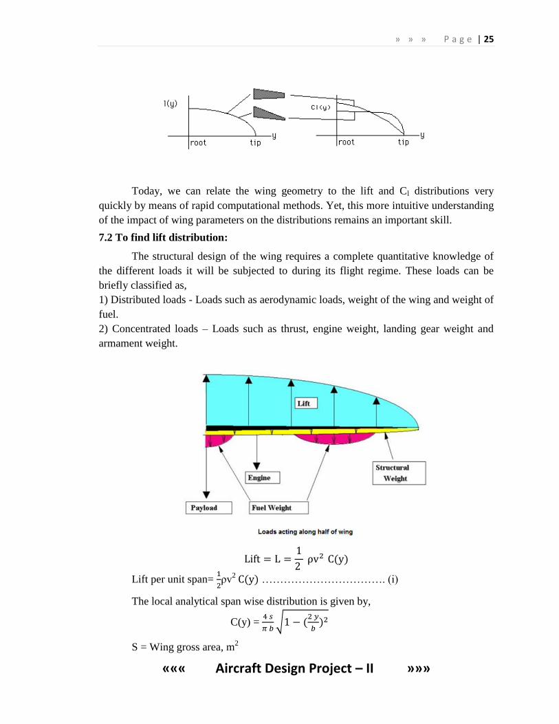
7.2 To find lift distribution:
The structural design of the wing requires a complete quantitative knowledge of
the different loads it will be subjected to during its flight regime. These loads can be
briefly classified as,
1) Distributed loads - Loads such as aerodynamic loads, weight of the wing and weight of
fuel.
2) Concentrated loads – Loads such as thrust, engine weight, landing gear weight and
armament weight.
Lift per unit span=
ρv
2 ……………………………. (i)
The local analytical span wise distribution is given by,
C(y) =
√
S = Wing gross area, m2
» » » P a g e | 26
««« Aircraft Design Project – II »»»
b = Span, m
y = span wise coordinate of the wing, m
Cl = Local lift coefficient
= Mean lift coefficient
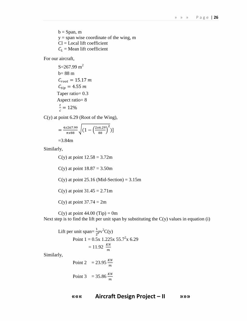
For our aircraft,
S=267.99 m2
b= 88 m
Taper ratio= 0.3
Aspect ratio= 8
C(y) at point 6.29 (Root of the Wing),
√ (
)
=3.84m
Similarly,
C(y) at point 12.58 = 3.72m
C(y) at point 18.87 = 3.50m
C(y) at point 25.16 (Mid-Section) = 3.15m
C(y) at point 31.45 = 2.71m
C(y) at point 37.74 = 2m
C(y) at point 44.00 (Tip) = 0m
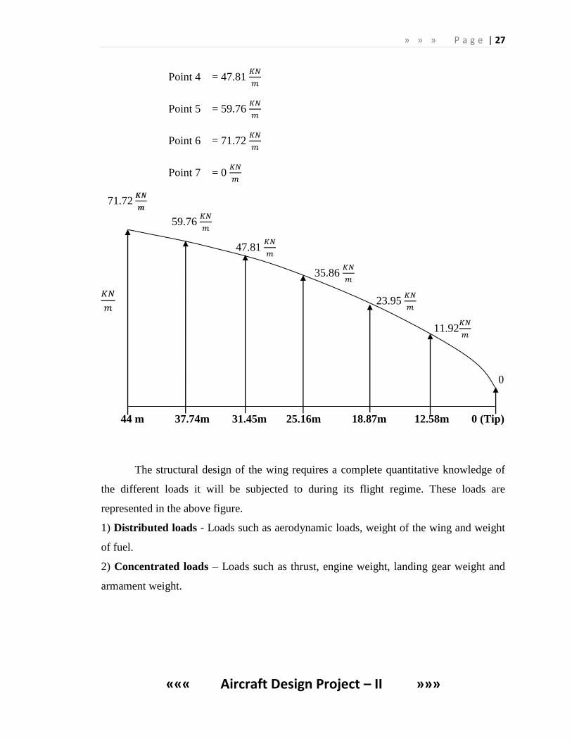
Next step is to find the lift per unit span by substituting the C(y) values in equation (i)
Lift per unit span=
ρv
2C(y)
Point 1 = 0.5x 1.225x 55.72x 6.29
= 11.92
Similarly,
Point 2 = 23.95
Point 3 = 35.86
» » » P a g e | 27
««« Aircraft Design Project – II »»»
Point 4 = 47.81
Point 5 = 59.76
Point 6 = 71.72
Point 7 = 0
71.72
59.76
47.81
35.86
23.95
11.92
0
44 m 37.74m 31.45m 25.16m 18.87m 12.58m 0 (Tip)
The structural design of the wing requires a complete quantitative knowledge of
the different loads it will be subjected to during its flight regime. These loads are
represented in the above figure.
1) Distributed loads - Loads such as aerodynamic loads, weight of the wing and weight
of fuel.
2) Concentrated loads – Loads such as thrust, engine weight, landing gear weight and
armament weight.
» » » P a g e | 28
««« Aircraft Design Project – II »»»
7.3. SHEAR FORCE AND BENDING MOMENT ANALYSIS ON THE WING:
The wing structure can be considered to be a cantilever beam, which is rigidly
supported at the wing root. The critical loads that need to be determined are the shear
forces and bending moments along the span of the wing. These take into account the
loads on the wing produced by the aerodynamic forces and component weights.
To determine the shear force and bending moments along the span, it is useful to
divide the wing into span wise segments of width ∆y. The elements will be subjected to
distributed load W(y). The resultant load acting on the element is then W(y) ∆y. In the
limit, as ∆y goes to zero, ∆y approaches the differential length, dy and the resultant load
is W(y) dy.
The elements shear force, V, is related to the resultant load as
W=
V1 = 0
V2 =
V3 = V2 ……….
VN = VN-1
Note that the shear on element N must equal the sum of the resultant loads on the
wing.
In reality, there might be a small discrepancy due to the finite number of
elements in which the wing span is sub divided. However with the large difference of
elements the difference should be small.
The bending moment, M, acting on the element is related to the shear force by
V=
» » » P a g e | 29
««« Aircraft Design Project – II »»»
For the moments along the wing span, one should also start at the wing tip where
the moment on the element is zero.
M1 = 0
M2 =
M3 = M2 ……….
MN = MN-1
These formulas provide a good approximation of the distribution of the shear and
moment along the span of the wing.
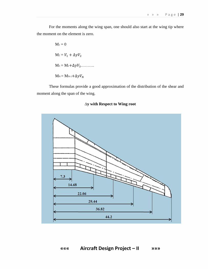
∆y with Respect to Wing root
» » » P a g e | 30
««« Aircraft Design Project – II »»»
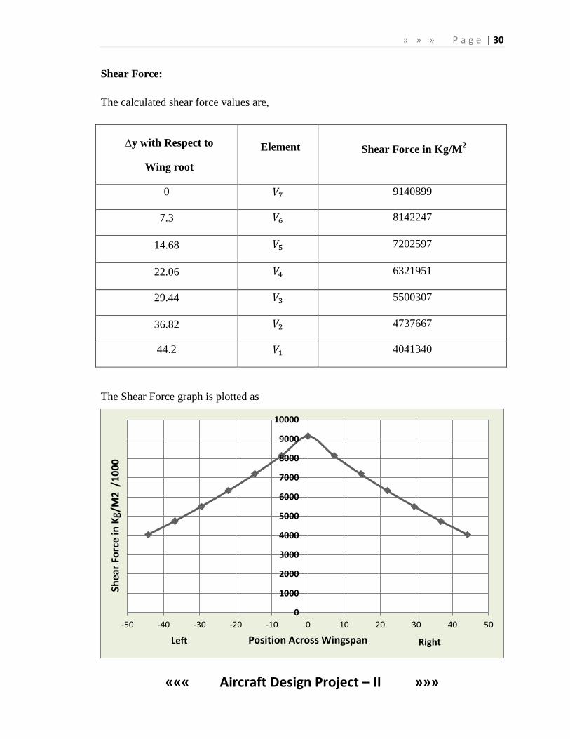
Shear Force:
The calculated shear force values are,
∆y with Respect to
Wing root
Element Shear Force in Kg/M2
0 9140899
7.3 8142247
14.68 7202597
22.06 6321951
29.44 5500307
36.82 4737667
44.2 4041340
The Shear Force graph is plotted as
0
1000
2000
3000
4000
5000
6000
7000
8000
9000
10000
-50 -40 -30 -20 -10 0 10 20 30 40 50
Shea
r Fo
rce
in K
g/M
2 /
10
00
Position Across Wingspan Left Right
» » » P a g e | 31
««« Aircraft Design Project – II »»»
The shear force along the span is found by dividing the wing into span wise segments
of width ∆y. The elements will be subjected to distributed load W(y). The resultant load acting
on the element is then W(y) ∆y. In the limit, as ∆y goes to zero, ∆y approaches the differential
length, dy, and the resultant load is W(y)dy. Thus the shear force graph plotted above shows
that the shear force is maximum at the root tip since the wing behaves like a cantilever beam
and the load at the end point produces more shear than at the root.
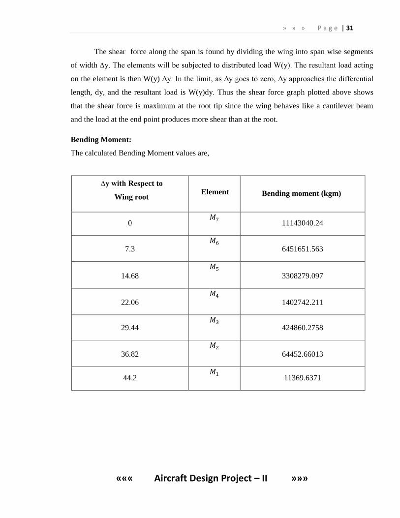
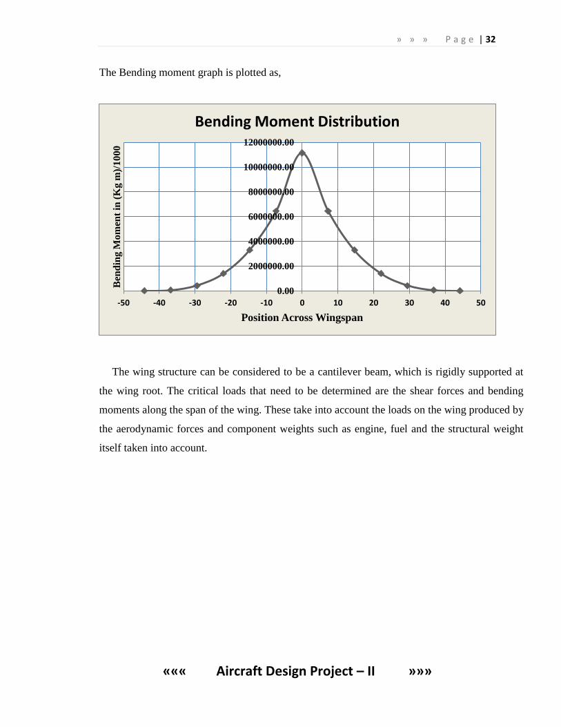
Bending Moment:
The calculated Bending Moment values are,
∆y with Respect to
Wing root Element Bending moment (kgm)
0
11143040.24
7.3
6451651.563
14.68
3308279.097
22.06
1402742.211
29.44
424860.2758
36.82
64452.66013
44.2
11369.6371
» » » P a g e | 32
««« Aircraft Design Project – II »»»
The Bending moment graph is plotted as,
The wing structure can be considered to be a cantilever beam, which is rigidly supported at
the wing root. The critical loads that need to be determined are the shear forces and bending
moments along the span of the wing. These take into account the loads on the wing produced by
the aerodynamic forces and component weights such as engine, fuel and the structural weight
itself taken into account.
0.00
2000000.00
4000000.00
6000000.00
8000000.00
10000000.00
12000000.00
-50 -40 -30 -20 -10 0 10 20 30 40 50
Ben
din
g M
om
ent
in (
Kg
m)/
10
00
Position Across Wingspan
Bending Moment Distribution
» » » P a g e | 33
««« Aircraft Design Project – II »»»
8. FUSELAGE DESIGN:
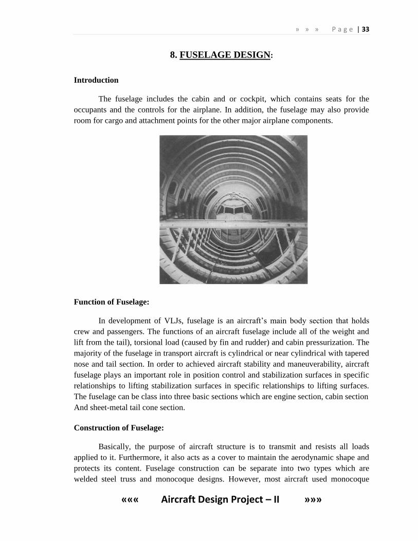
Introduction
The fuselage includes the cabin and or cockpit, which contains seats for the
occupants and the controls for the airplane. In addition, the fuselage may also provide
room for cargo and attachment points for the other major airplane components.
Function of Fuselage:
In development of VLJs, fuselage is an aircraft’s main body section that holds
crew and passengers. The functions of an aircraft fuselage include all of the weight and
lift from the tail), torsional load (caused by fin and rudder) and cabin pressurization. The
majority of the fuselage in transport aircraft is cylindrical or near cylindrical with tapered
nose and tail section. In order to achieved aircraft stability and maneuverability, aircraft
fuselage plays an important role in position control and stabilization surfaces in specific
relationships to lifting stabilization surfaces in specific relationships to lifting surfaces.
The fuselage can be class into three basic sections which are engine section, cabin section
And sheet-metal tail cone section.
Construction of Fuselage:
Basically, the purpose of aircraft structure is to transmit and resists all loads
applied to it. Furthermore, it also acts as a cover to maintain the aerodynamic shape and
protects its content. Fuselage construction can be separate into two types which are
welded steel truss and monocoque designs. However, most aircraft used monocoque
» » » P a g e | 34
««« Aircraft Design Project – II »»»
design in their structure in order to carry various loads. The monocoque design can be
categorized into three classes which are monocoque, semi monocoque and reinforced
shell.
Standard aluminum fuselage of a big passenger airplane is a semi monocoque
Construction with shell, stringers and frames. The fuselage contains a cockpit and
passenger compartment, both sections experiencing surplus internal pressure i.e.
hermetic.
There are three commonly used fuselage designs, they are,
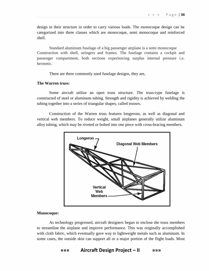
The Warren truss:
Some aircraft utilize an open truss structure. The truss-type fuselage is
constructed of steel or aluminum tubing. Strength and rigidity is achieved by welding the
tubing together into a series of triangular shapes, called trusses.
Construction of the Warren truss features longerons, as well as diagonal and
vertical web members. To reduce weight, small airplanes generally utilize aluminum
alloy tubing, which may be riveted or bolted into one piece with cross-bracing members.
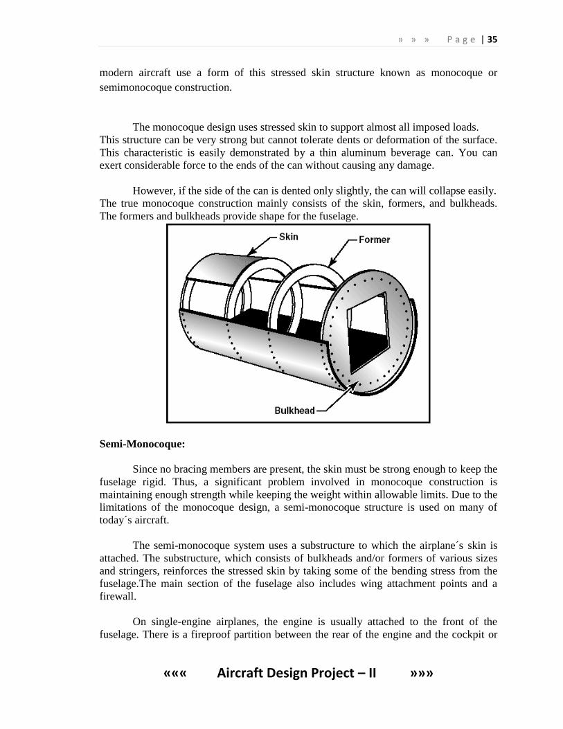
Monocoque:
As technology progressed, aircraft designers began to enclose the truss members
to streamline the airplane and improve performance. This was originally accomplished
with cloth fabric, which eventually gave way to lightweight metals such as aluminum. In
some cases, the outside skin can support all or a major portion of the flight loads. Most
» » » P a g e | 35
««« Aircraft Design Project – II »»»
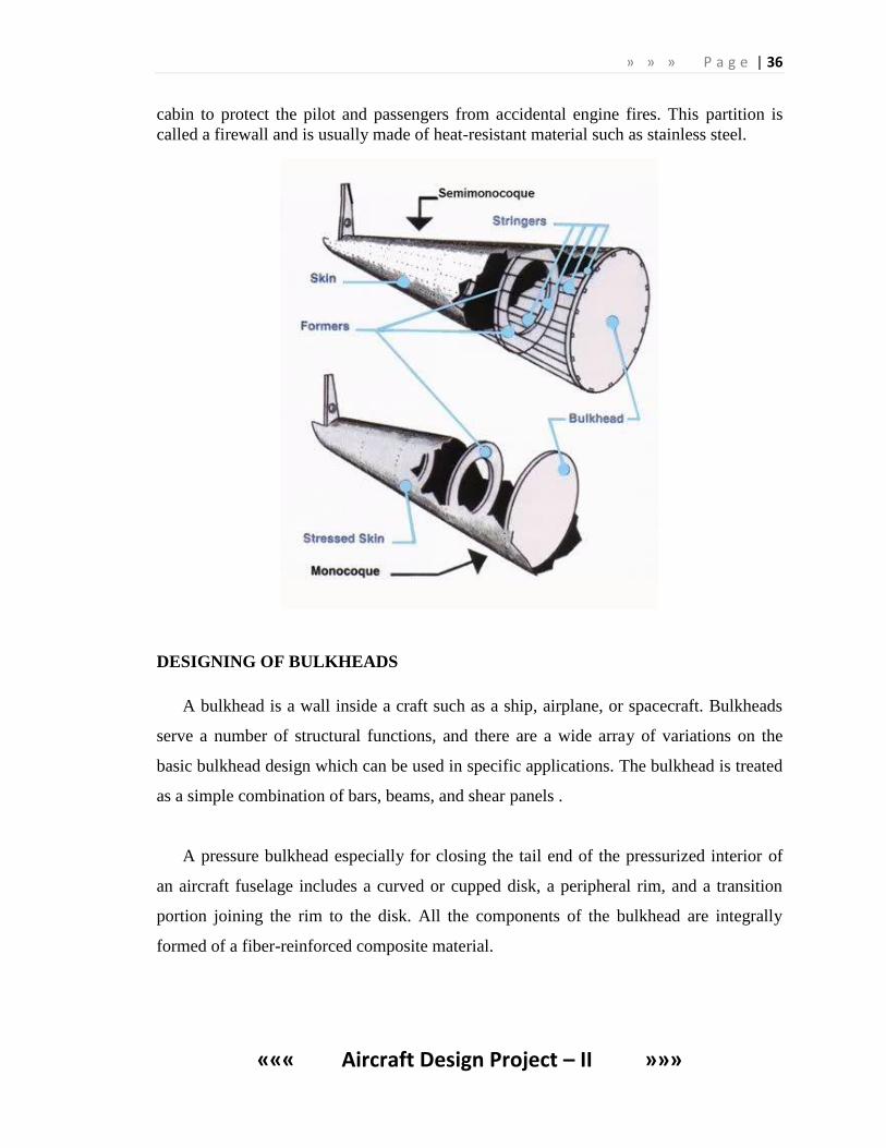
modern aircraft use a form of this stressed skin structure known as monocoque or
semimonocoque construction.
The monocoque design uses stressed skin to support almost all imposed loads.
This structure can be very strong but cannot tolerate dents or deformation of the surface.
This characteristic is easily demonstrated by a thin aluminum beverage can. You can
exert considerable force to the ends of the can without causing any damage.
However, if the side of the can is dented only slightly, the can will collapse easily.
The true monocoque construction mainly consists of the skin, formers, and bulkheads.
The formers and bulkheads provide shape for the fuselage.
Semi-Monocoque:
Since no bracing members are present, the skin must be strong enough to keep the
fuselage rigid. Thus, a significant problem involved in monocoque construction is
maintaining enough strength while keeping the weight within allowable limits. Due to the
limitations of the monocoque design, a semi-monocoque structure is used on many of
today´s aircraft.
The semi-monocoque system uses a substructure to which the airplane´s skin is
attached. The substructure, which consists of bulkheads and/or formers of various sizes
and stringers, reinforces the stressed skin by taking some of the bending stress from the
fuselage.The main section of the fuselage also includes wing attachment points and a
firewall.
On single-engine airplanes, the engine is usually attached to the front of the
fuselage. There is a fireproof partition between the rear of the engine and the cockpit or
» » » P a g e | 36
««« Aircraft Design Project – II »»»
cabin to protect the pilot and passengers from accidental engine fires. This partition is
called a firewall and is usually made of heat-resistant material such as stainless steel.
DESIGNING OF BULKHEADS
A bulkhead is a wall inside a craft such as a ship, airplane, or spacecraft. Bulkheads
serve a number of structural functions, and there are a wide array of variations on the
basic bulkhead design which can be used in specific applications. The bulkhead is treated
as a simple combination of bars, beams, and shear panels .
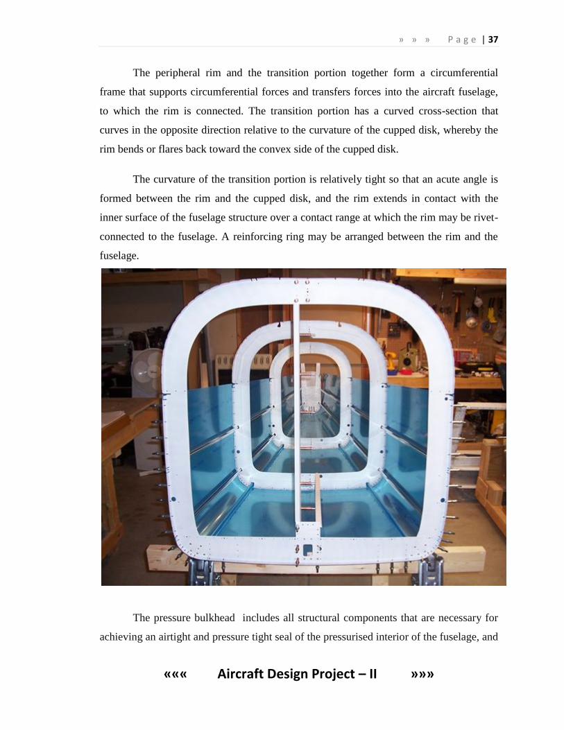
A pressure bulkhead especially for closing the tail end of the pressurized interior of
an aircraft fuselage includes a curved or cupped disk, a peripheral rim, and a transition
portion joining the rim to the disk. All the components of the bulkhead are integrally
formed of a fiber-reinforced composite material.
» » » P a g e | 37
««« Aircraft Design Project – II »»»
The peripheral rim and the transition portion together form a circumferential
frame that supports circumferential forces and transfers forces into the aircraft fuselage,
to which the rim is connected. The transition portion has a curved cross-section that
curves in the opposite direction relative to the curvature of the cupped disk, whereby the
rim bends or flares back toward the convex side of the cupped disk.
The curvature of the transition portion is relatively tight so that an acute angle is
formed between the rim and the cupped disk, and the rim extends in contact with the
inner surface of the fuselage structure over a contact range at which the rim may be rivet-
connected to the fuselage. A reinforcing ring may be arranged between the rim and the
fuselage.
The pressure bulkhead includes all structural components that are necessary for
achieving an airtight and pressure tight seal of the pressurised interior of the fuselage, and
» » » P a g e | 38
««« Aircraft Design Project – II »»»
for taking up and further transmitting into the fuselage structure all of the forces that
result from the pressure difference on the two opposite sides of the bulkhead.
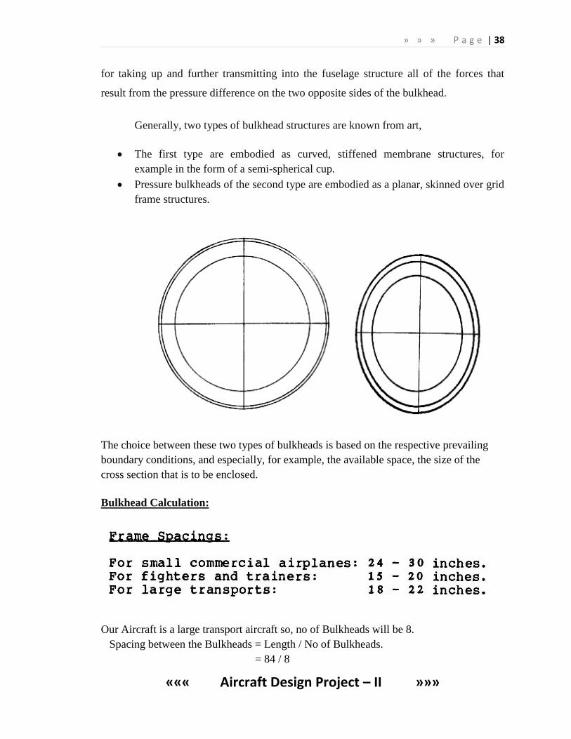
Generally, two types of bulkhead structures are known from art,
The first type are embodied as curved, stiffened membrane structures, for
example in the form of a semi-spherical cup.
Pressure bulkheads of the second type are embodied as a planar, skinned over grid
frame structures.
The choice between these two types of bulkheads is based on the respective prevailing
boundary conditions, and especially, for example, the available space, the size of the
cross section that is to be enclosed.
Bulkhead Calculation:
Our Aircraft is a large transport aircraft so, no of Bulkheads will be 8.
Spacing between the Bulkheads = Length / No of Bulkheads.
= 84 / 8
» » » P a g e | 39
««« Aircraft Design Project – II »»»
= 10.5 m
No of Frames = (Length / Spacing for Frames) – (Length / No of Bulkheads).
= (84 / 0.5588) – 10.5
= 139.8
No of Frames = 140
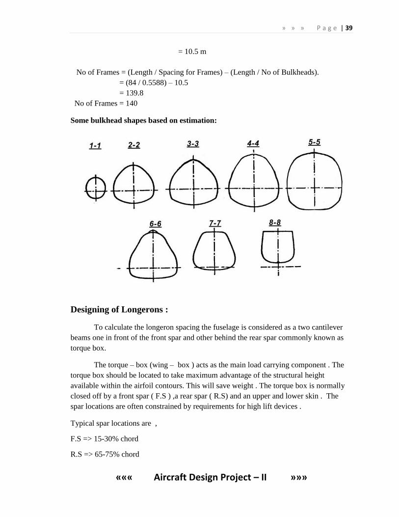
Some bulkhead shapes based on estimation:
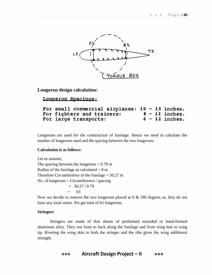
Designing of Longerons :
To calculate the longeron spacing the fuselage is considered as a two cantilever
beams one in front of the front spar and other behind the rear spar commonly known as
torque box.
The torque – box (wing – box ) acts as the main load carrying component . The
torque box should be located to take maximum advantage of the structural height
available within the airfoil contours. This will save weight . The torque box is normally
closed off by a front spar ( F.S ) ,a rear spar ( R.S) and an upper and lower skin . The
spar locations are often constrained by requirements for high lift devices .
Typical spar locations are ,
F.S => 15-30% chord
R.S => 65-75% chord
» » » P a g e | 40
««« Aircraft Design Project – II »»»
Longeron design calculation:
Longerons are used for the construction of fuselage. Hence we need to calculate the
number of longerons used and the spacing between the two longerons.
Calculation is as follows:
Let us assume,
The spacing between the longerons = 0.79 m
Radius of the fuselage as calculated = 8 m
Therefore Circumference of the fuselage = 50.27 m
No. of longerons = Circumference / spacing
= 50.27 / 0.79
= 63
Now we decide to remove the two longerons placed at 0 & 180 degrees as, they do not
have any axial stress. We get total of 61 longerons.
Stringers
Stringers are made of thin sheets of preformed extruded or hand-formed
aluminum alloy. They run front to back along the fuselage and from wing butt to wing
tip. Riveting the wing skin to both the stringer and the ribs gives the wing additional
strength.
» » » P a g e | 41
««« Aircraft Design Project – II »»»
9. MATERIAL SELECTION:
For many years, aircraft designers could propose theoretical designs that they
could not build because the materials needed to construct them did not exist. (The term
"unobtainium" is sometimes used to identify materials that are desired but not yet
available.)
In the early days of flight, before World War I, aircraft were constructed entirely
of wood and canvas. They were shaped and joined by skilled craftsmen, many of whom
were drawn from other woodworking trades. Every aircraft was unique, reflecting many
different thoughts and constant design changes. The beginning of World War I brought a
sudden demand for thousands of aircraft. This meant that factories had to accommodate
large-scale manufacture and assembly of aircraft components by unskilled workers.
Small companies grew into major manufacturers capable of producing many different
types of aircraft in large numbers.
The techniques for building aircraft evolved gradually during the years between
the wars. Wood and canvas changed to aluminium as the principal structural material
while designs improved and records were set and broken. Monoplanes (single wing
aircraft) were becoming more popular than biplanes (two wing aircraft). More power-ful
and reliable aircraft engines were continually being developed to increase pay-loads and
ranges. Because of the increased reliability and improved comfort, aircraft became a
more acceptable form of freight and passenger transport.
Material requirements for aircraft building:
1.small weight
2.high specific strength
3.heat resistance
4.fatigue load resistance
5.crack resistance
6.corrosion resistance
» » » P a g e | 42
««« Aircraft Design Project – II »»»
Raw Materials:
Materials used in aircraft are roughly the same regardless of the type of aircraft
involved (normal and transport category airplanes and/or rotorcraft). Aircraft are
obviously made up of different types of materials. Everything from plastics to metal
alloys to composites. Most commercial aircraft nowadays are excellent examples of the
advancements and developments in standard materials. All of these materials have seen
incredible improvements and refinements over the past 100 years. These recent
advancements have been unheard of in any time in human history.
The principal material used in modern fighter air-craft manufacturing is
Steel, Aluminium and Titanium alloys but the use of composite materials is rapidly
increasing. Composite materials are structural materials made up of two or more
contrasting components, normally fine fibers or whiskers in a bonding resin.
Composites such as carbon epoxies, graphite, fiberglass, carbon fiber reinforced
plastics (CFRP), boron fiber reinforced plastics (BFRP), and glass reinforced
plastics (GRP) enable manufacturers to build aircraft that are lighter and
stronger than aluminium models. Steel alloys, titanium, stainless steel, and
magnesium castings are also used, but in much smaller quantities.
COMPOSITES:
For many years, aircraft designers could propose theoretical designs that they
could not build because the materials needed to construct them did not exist. (The term
"unobtainium" is sometimes used to identify materials that are desired but not yet
available.) For instance, large space planes like the Space Shuttle would have proven
extremely difficult, if not impossible, to build without heat-resistant ceramic tiles to
protect them during reentry. And high-speed forward-swept-wing airplanes like
Grumman's experimental X-29 or the Russian Sukhoi S-27 Berkut would not have been
possible without the development of composite materials to keep their wings from
bending out of shape.
Composites are the most important materials to be adapted for aviation since the
use of aluminum in the 1920s. Composites are materials that are combinations of two or
» » » P a g e | 43
««« Aircraft Design Project – II »»»
more organic or inorganic components. One material serves as a "matrix," which is the
material that holds everything together, while the other material serves as reinforcement,
in the form of fibers embedded in the matrix. Until recently, the most common matrix
materials were "thermosetting" materials such as epoxy, bismaleimide, or polyimide. The
reinforcing materials can be glass fiber, boron fiber, carbon fiber, or other more exotic
mixtures.
Fiberglass is the most common composite material, and consists of glass fibers
embedded in a resin matrix. Fiberglass was first used widely in the 1950s for boats and
automobiles, and today most cars have fiberglass bumpers covering a steel frame.
Fiberglass was first used in the Boeing 707 passenger jet in the 1950s, where it comprised
about two percent of the structure. By the 1960s, other composite materials became
available, in particular boron fiber and graphite, embedded in epoxy resins. The U.S. Air
Force and U.S. Navy began research into using these materials for aircraft control
surfaces like ailerons and rudders. The first major military production use of boron fiber
was for the horizontal stabilizers on the Navy's F-14 Tomcat interceptor. By 1981, the
British Aerospace-McDonnell Douglas AV-8B Harrier flew with over 25 percent of its
structure made of composite materials.
Making composite structures is more complex than manufacturing most metal
structures. To make a composite structure, the composite material, in tape or fabric form,
is laid out and put in a mold under heat and pressure. The resin matrix material flows and
when the heat is removed, it solidifies. It can be formed into various shapes. In some
cases, the fibers are wound tightly to increase strength. One useful feature of composites
is that they can be layered, with the fibers in each layer running in a different direction.
This allows materials engineers to design structures that behave in certain ways. For
instance, they can design a structure that will bend in one direction, but not another. The
designers of the Grumman X-29 experimental plane used this attribute of composite
materials to design forward-swept wings that did not bend up at the tips like metal wings
of the same shape would have bent in flight.
» » » P a g e | 44
««« Aircraft Design Project – II »»»
The greatest value of composite materials is that they can be both lightweight and
strong. The heavier an aircraft weighs, the more fuel it burns, so reducing weight is
important to aeronautical engineers.
Despite their strength and low weight, composites have not been a miracle
solution for aircraft structures. Composites are hard to inspect for flaws. Some of them
absorb moisture. Most importantly, they can be expensive, primarily because they are
labor intensive and often require complex and expensive fabrication machines.
Aluminum, by contrast, is easy to manufacture and repair. Anyone who has ever gotten
into a minor car accident has learned that dented metal can be hammered back into shape,
but a crunched fiberglass bumper has to be completely replaced. The same is true for
many composite materials used in aviation.
Modern airliners use significant amounts of composites to achieve lighter weight.
About ten percent of the structural weight of the Boeing 777, for instance, is composite
material. Modern military aircraft, such as the F-22, use composites for at least a third of
their structures, and some experts have predicted that future military aircraft will be more
than two-thirds composite materials. But for now, military aircraft use substantially
greater percentages of composite materials than commercial passenger aircraft primarily
because of the different ways that commercial and military aircraft are maintained.
Aluminum is a very tolerant material and can take a great deal of punishment
before it fails. It can be dented or punctured and still hold together. Composites are not
like this. If they are damaged, they require immediate repair, which is difficult and
expensive. An airplane made entirely from aluminum can be repaired almost anywhere.
This is not the case for composite materials, particularly as they use different and more
exotic materials. Because of this, composites will probably always be used more in
military aircraft, which are constantly being maintained, than in commercial aircraft,
which have to require less maintenance.
Thermoplastics are a relatively new material that is replacing thermosets as the
matrix material for composites. They hold much promise for aviation applications. One
» » » P a g e | 45
««« Aircraft Design Project – II »»»
of their big advantages is that they are easy to produce. They are also more durable and
tougher than thermosets, particularly for light impacts, such as when a wrench dropped
on a wing accidentally. The wrench could easily crack a thermoset material but would
bounce off a thermoplastic composite material.
In addition to composites, other advanced materials are under development for
aviation. During the 1980s, many aircraft designers became enthusiastic about ceramics,
which seemed particularly promising for lightweight jet engines, because they could
tolerate hotter temperatures than conventional metals. But their brittleness and difficulty
to manufacture were major drawbacks, and research on ceramics for many aviation
applications decreased by the 1990s.
SHEET METAL CONSTRUCTION:
Sheet metal aircraft construction is the most prevalent aircraft construction
material by all measures, used extensively from jetliners to light, single engine airplanes
and kits over the past five decades. Common sheet-metal construction is most accurately
described as "aluminium-alloy, semi-monocoque, and stressed skin construction." This
means that the metal used is some form of aluminium-based alloy, and that the airframe
sections are designed and built so that the outer skin itself is part of the structure, with
internal ribs, longerons, and bulkheads to distribute the loads. The metal parts are
permanently joined with rivets or other fasteners.
Sheet-metal aircraft construction became a popular replacement to steel-tube (or
wood) airframes covered by fabric because of its numerous advantages: Metal
construction is more efficient because it does not need both a framework for structural
strength (often accompanied by exterior braces) and a separate covering skin to provide
the aerodynamic shape of the aircraft. Furthermore, sheet-metal is not as delicate as
fabric, and not subject to on-going damage by moisture and sunlight (UV rays).
Aluminium-alloy construction is stronger yet lighter, while being very durable. By
designing structural members to carry the required loads and to resist stress in relation to
the physical characteristics of the metal parts and fasteners, a metal aircraft provides
superior strength and durability while lowering weight (thus increasing performance).
» » » P a g e | 46
««« Aircraft Design Project – II »»»
New and modern metal alloys and materials have allowed aviation technology to
advance, and is the reason it continues to dominate over other aircraft building methods.
Aluminium’s unique combination of properties makes it one of the most versatile
engineering and building materials in existence:
Low weight / high strength relationship;
Corrosion resistance, especially with newer alloys and modern primers;
Low cost and widespread availability;
Proven durability and resistance to sun and moisture
Existence of vast amounts of empirical data on its properties
Easy to work with: requires simple tools and processes, and does not
require a temperature-controlled or dust-free environment, as with
composites. Modern blind rivet fasteners have greatly simplified all-metal
kit aircraft construction;
Malleability: easy to form into many shapes, with almost no limit to the
shapes it can be formed into;
Environmentally friendly: no health hazards to worry about when working
with sheet metal; recyclable;
Easy to inspect: construction or materials flaws are easily detected, as are
defective parts and damage.
Simple to repair: rivets and fasteners can be easily removed to replace
damaged parts or sections, and individual parts can be replaced without
having to replace or rework an entire airframe section.
Additionally, a well-designed sheet-metal aircraft provides superior
crashworthiness over other types, as an impact’s energy is absorbed by progressively
collapsing the metal structure, as opposed to splintering or shattering upon impact.
Another important advantage often overlooked is the inherent lightning protection that a
metal airframe offers.
2024-T4 and 6061-T6 are two of the most common alloys used in kit aircraft
today, and are readily available in many forms at affordable prices. The more modern
» » » P a g e | 47
««« Aircraft Design Project – II »»»
6061-T6 alloy is a very versatile alloy for aircraft construction, providing superior
corrosion resistance, good formability (easy to work with), and flexibility and strength.
The following list indicates the approximate specific strength for some materials:
Aluminium - 30 Mpa
Mild Steel - 51 MPa
Duralumin (heat treated) - 150 MPa
Al-Zn (heat treated) - 220 Mpa
Titanium alloy (heat treated) - 270 Mpa
TITANIUM ALLOYS FOR AIRCRAFT APPLICATIONS:
Aluminium was widely used in subsonic aircraft. Aerotechnics of supersonic
speeds faced with elevated temperatures of the aircraft skin for which aluminium cannot
be applied due to low heat resistance. Structural materials reliably operating in
complicated combination of force and temperature fields under the influence of corrosive
media, radiation and high pressures were required. Titanium and its alloys meet this
requirement.
Currently a greater amount of titanium is incorporated in to aircraft. This is
connected with the fact that the share of the composite materials with which aluminium
intensively interacts and corrodes in the new airplanes is being increased. Titanium is not
subjected to these processes and results in increasing the life of components.
Three major trends of titanium application for aircraft building:
1.fabrication of items of complex space configuration:
- hatch and door edging where moisture is likely to be accumulated (high
corrosion resistance of titanium is used)
- skins which are affected by engine combustion product flow, flame preventing
fire safety-proof membranes (high temperature of melting and chemical inactivity of
titanium is used)
- thin-walled lead pipes of air system (minimum thermal titanium extension ratio
» » » P a g e | 48
««« Aircraft Design Project – II »»»
compared to all other metals is used)
- floor decking of the cargo cabin (high strength and hardness is used)
2.fabrication of designated high-loaded assemblies and units
- landing gear
- fastening elements (brackets) of the wing
- hydro cylinders
3.engine part manufacture.
The following is manufactured from titanium alloys for aircraft applications:
Ailerons, panel and swivel wing assemblies, spar walls, panels, brackets, steering
wheels, wedge meshes, air intake ducts, lead pipes, frames, leading edge flaps and flaps,
hydraulic systems, fasteners and a number of other parts.
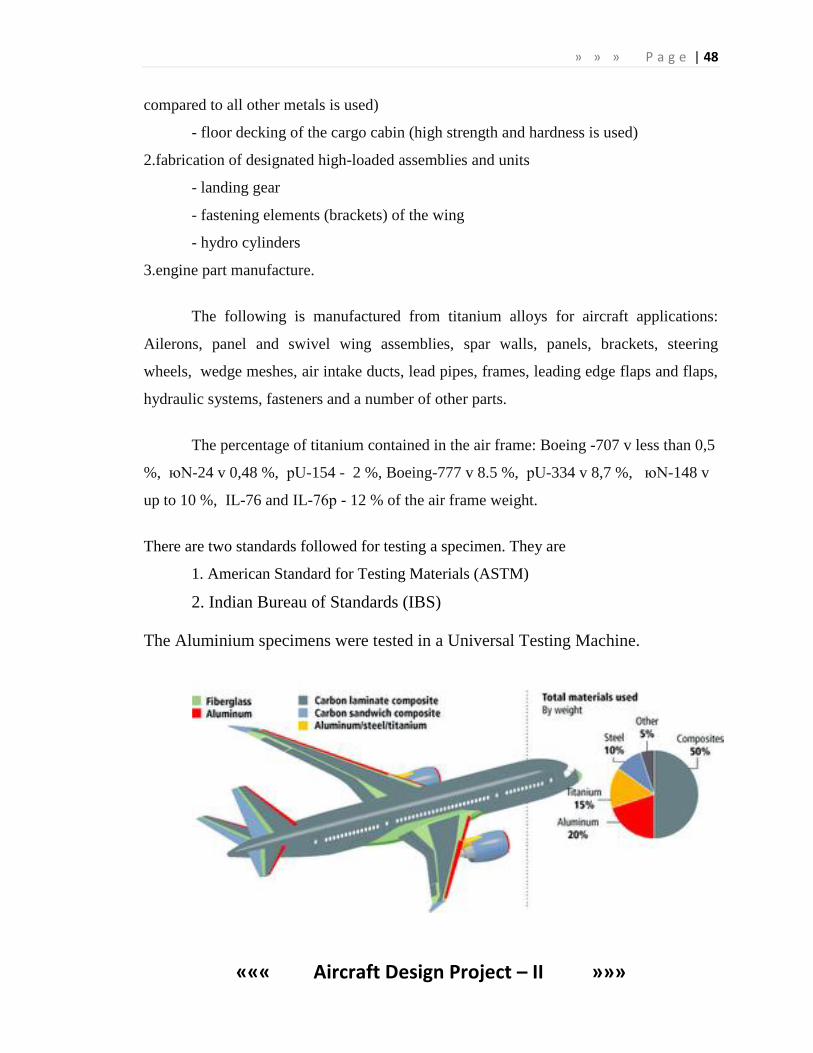
The percentage of titanium contained in the air frame: Boeing -707 v less than 0,5
%, юN-24 v 0,48 %, рU-154 - 2 %, Boeing-777 v 8.5 %, рU-334 v 8,7 %, юN-148 v
up to 10 %, IL-76 and IL-76р - 12 % of the air frame weight.
There are two standards followed for testing a specimen. They are
1. American Standard for Testing Materials (ASTM)
2. Indian Bureau of Standards (IBS)
The Aluminium specimens were tested in a Universal Testing Machine.
» » » P a g e | 49
««« Aircraft Design Project – II »»»
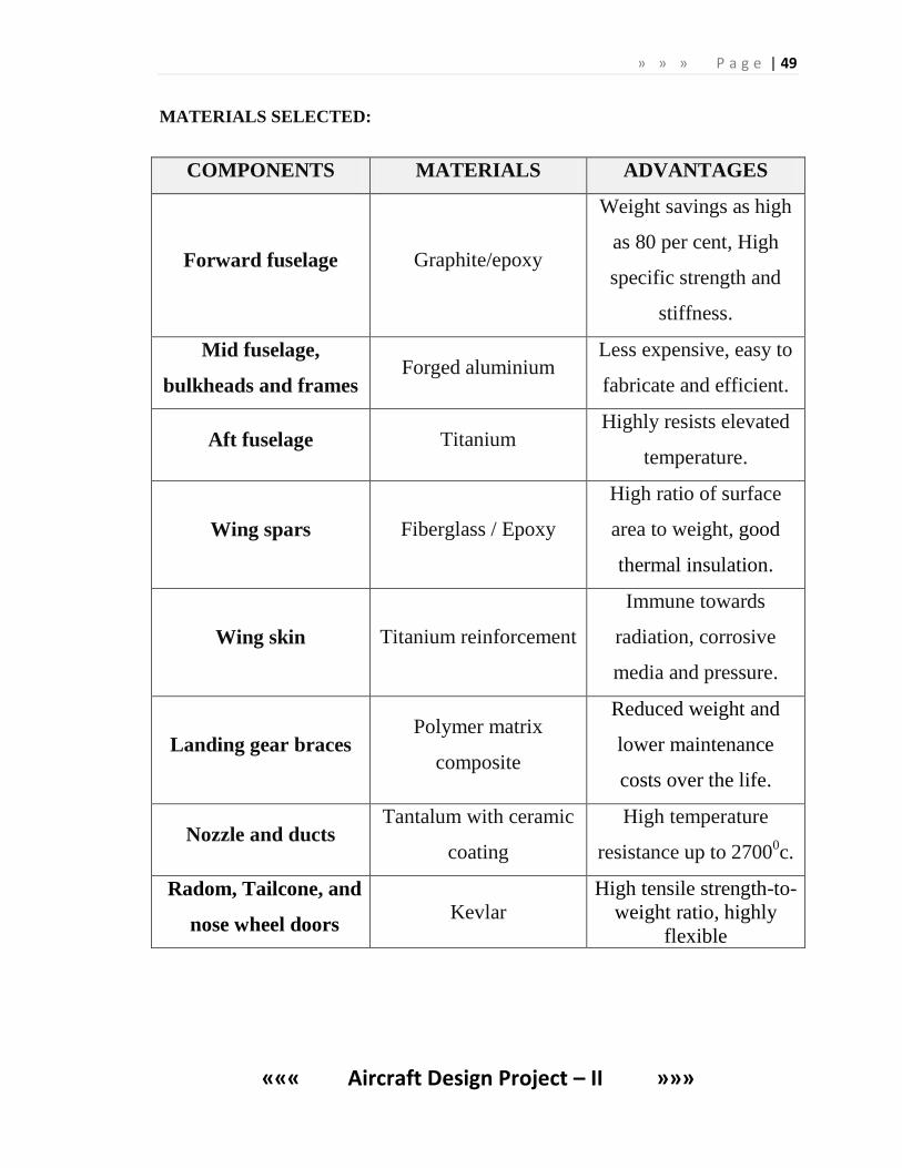
MATERIALS SELECTED:
COMPONENTS MATERIALS ADVANTAGES
Forward fuselage Graphite/epoxy
Weight savings as high
as 80 per cent, High
specific strength and
stiffness.
Mid fuselage,
bulkheads and frames Forged aluminium
Less expensive, easy to
fabricate and efficient.
Aft fuselage Titanium Highly resists elevated
temperature.
Wing spars Fiberglass / Epoxy
High ratio of surface
area to weight, good
thermal insulation.
Wing skin Titanium reinforcement
Immune towards
radiation, corrosive
media and pressure.
Landing gear braces Polymer matrix
composite
Reduced weight and
lower maintenance
costs over the life.
Nozzle and ducts Tantalum with ceramic
coating
High temperature
resistance up to 27000c.
Radom, Tailcone, and
nose wheel doors Kevlar
High tensile strength-to-
weight ratio, highly
flexible
» » » P a g e | 50
««« Aircraft Design Project – II »»»
GRAPHITE/EPOXY:
Polymer matrix composites are being used increasingly in a variety of important
applications because of their excellent mechanical properties and low weight, combined
with advancements in manufacturing technology. In particular, graphite fiber reinforced
epoxy composites are playing an important role in the production of high performance
vehicles as well as critical aerospace structures and primary structures of commercial and
military aircraft. For these applications, the safety and reliability of these materials must
be assured.
Weight savings as high as 80 per cent could be achieved if graphite polymer
composites could replace aluminium in structures such as electromagnetic interference
shielding covers and grounding planes. This could result in significant cost savings,
especially for the mobile electronics found in spacecraft, aircraft, automobiles, and hand-
held consumer electronics. However, such composites had not yet been fabricated with
conductivity sufficient to enable these applications.
The specific strength and stiffness of graphite epoxy composites are significantly
greater than monolithic materials such as steel and aluminium, which make them
attractive for numerous weight critical applications.
FIBER GLASS AND POLYMER MATRIX COMPOSITE:
Composites are broadly known as reinforced plastics. Specifically, composites are
a reinforcing fiber in a polymer matrix, most commonly; the reinforcing fiber is
fiberglass, although high strength fibers such as aramid and carbon are used in advanced
applications, the polymer matrix is a thermoset resin, with polyester, vinyl ester, and
epoxy resins most often the matrix of choice. Specialized resins such as, phenolic,
polyurethane can also be used.
The unique properties of Fiberglass make it suitable for a wide range of product
applications, and also offer advantages that are not found in more conventional
constructional materials.
» » » P a g e | 51
««« Aircraft Design Project – II »»»
KEVLAR:
Kevlar is the registered trademark for a para-aramid synthetic fiber, related to
other aramids such as Nomex and Technora. Developed at DuPont in 1965, this high
strength material was first commercially used in the early 1970s as a replacement for
steel in racing tires. Typically it is spun into ropes or fabric sheets that can be used as
such or as an ingredient in composite material components.
Currently, Kevlar has many applications, ranging from bicycle tires and racing
sails to body armor because of its high tensile strength-to-weight ratio—famously: "...5
times stronger than steel on an equal weight basis..." When used as a woven material, it
is suitable for mooring lines and other underwater applications.
BORON FIBER:
Specialty Materials’ boron fiber is particularly desirable for use in aerospace
industry applications where high compression loads are present. Some examples of these
applications include the following aircraft: F-15 Fighter, F-14 Fighter, B1 Bomber,
Blackhawk Helicopter, Predator B UAV, and the Space Shuttle. Additionally, Specialty
Materials’ boron fiber has been used to repair aircraft structures in both military and
commercial aircraft including the B-52, C-130, F-4, F-5, F-111 and Boeing 727, 747, 757
and MD-11.
» » » P a g e | 52
««« Aircraft Design Project – II »»»
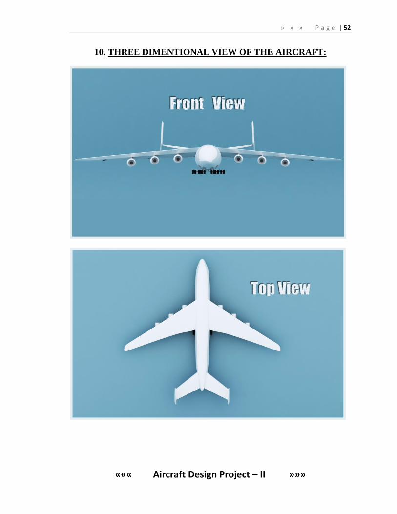
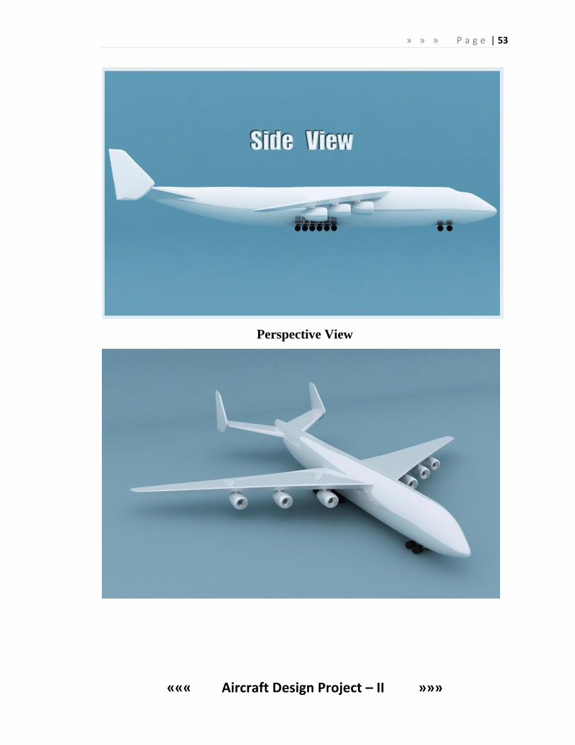
10. THREE DIMENTIONAL VIEW OF THE AIRCRAFT:
» » » P a g e | 53
««« Aircraft Design Project – II »»»
Perspective View
» » » P a g e | 54
««« Aircraft Design Project – II »»»
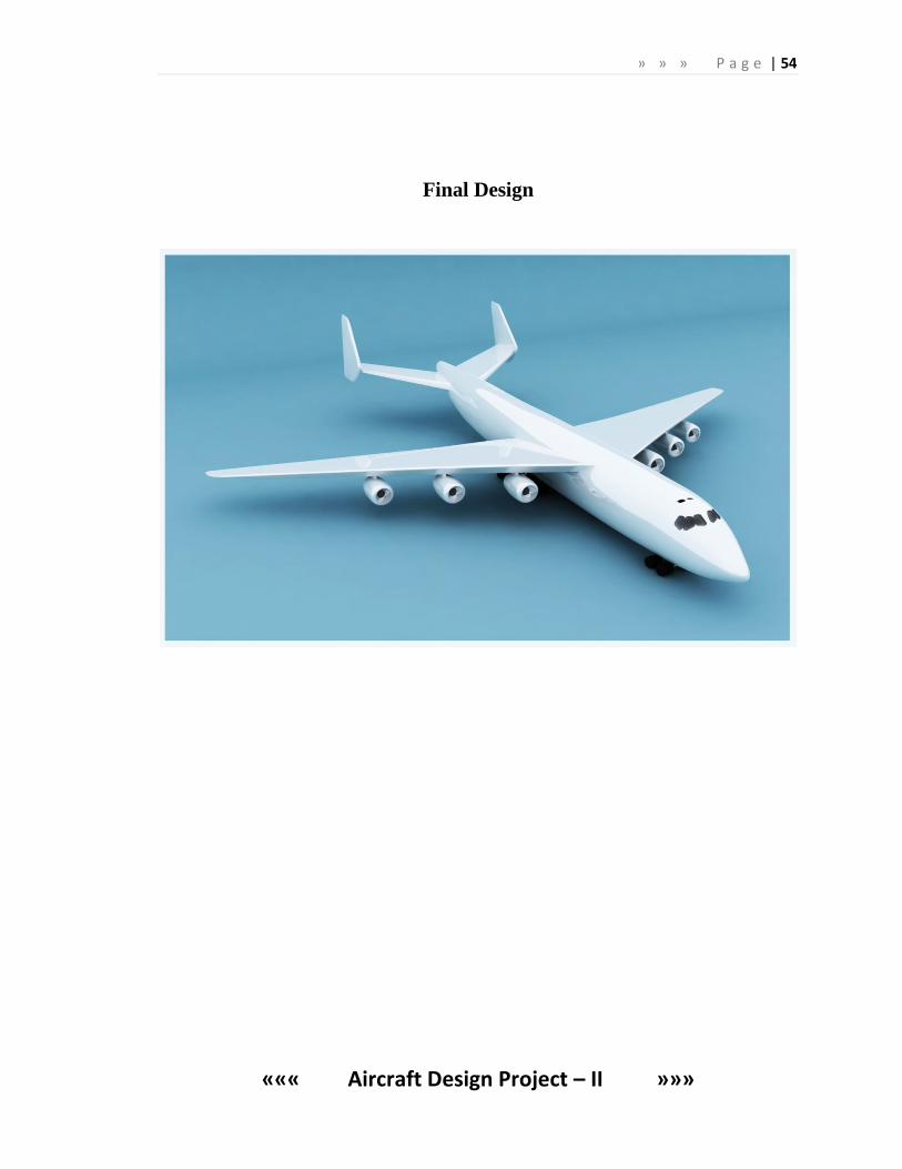
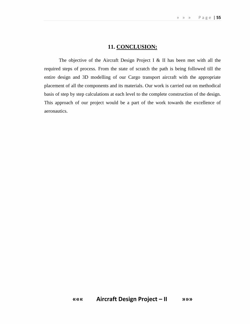
Final Design
» » » P a g e | 55
««« Aircraft Design Project – II »»»
11. CONCLUSION:
The objective of the Aircraft Design Project I & II has been met with all the
required steps of process. From the state of scratch the path is being followed till the
entire design and 3D modelling of our Cargo transport aircraft with the appropriate
placement of all the components and its materials. Our work is carried out on methodical
basis of step by step calculations at each level to the complete construction of the design.
This approach of our project would be a part of the work towards the excellence of
aeronautics.
» » » P a g e | 56
««« Aircraft Design Project – II »»»
12. BIBLIOGRAPHY
• Raymer DP, 2008, aircraft design: A Conceptual Approach, 4th
Ed.
• Jane’s the world’s aircraft flying manual, 2004-2005.
• JD. Anderson: Aircraft performance.
• Jan Roskam: Elements of aircraft preliminary design.
• JD.Anderson: Introduction to flight.
• Lloyd R.Jenkinson : Aircraft Design Projects
• Terrell E. Greene: Fighter aircraft performance modelling, simulation.
WEBSITE REFERENCES
1. www.wikipedia.org
2. www.naca/airfoil.htm
3. www.worldaircraftdirectory.com
4. www.boieng.com
5. www.airbus.com
6. www.airliners.com
7. www.airfoilinvestigation/database.htm
8. www.worldofkrauss.com