Embed Size (px)
DESCRIPTION
adsl
Citation preview
Broadband-Wireline Technologies
Faculty of Network PlanningALTTC, Ghaziabad.
2
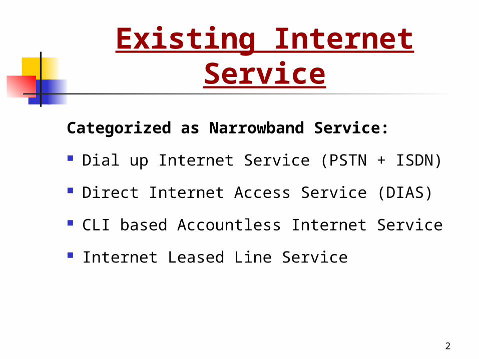
Existing Internet Service
Categorized as Narrowband Service:
Dial up Internet Service (PSTN + ISDN)
Direct Internet Access Service (DIAS)
CLI based Accountless Internet Service
Internet Leased Line Service
3
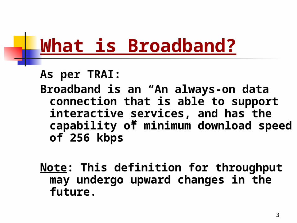
As per TRAI:Broadband is an “An always-on data
connection that is able to support interactive services, and has the capability of minimum download speed of 256 kbps”
Note: This definition for throughput may undergo upward changes in the future.
What is Broadband?
4
Advantages of Broadband
Always on ( Not on shared media)
Fast (speed ranging from 256 kbps to 2 Mbps)
No disconnection
No additional access charge
Telephone and Data simultaneously
Fat pipe has to be continuously supplemented with value
added applications to enjoy the advantage.
Digital Subscriber Line (DSL)
6
xDSL Family Tree xDSL
Symmetric DSL Provide identical data rates upstream & downstream
Asymmetric DSL Provide relatively lower rates upstream but higher
rates downstream Four main variations of xDSL exist:
ADSL-Asymmetrical Digital Sub’s Line HDSL-High bit/data rate Digital Sub’s Line SDSL-- Symmetric Digital Sub’s Line VDSL-Very-high-data-rate Digital Sub’s Line
7
DSL Technology DSL may offer more than 100 times the
network performance of a traditional analog modem
Precise speed of a connection depends upon the type of DSL employed
DSL uses the same telephone line as traditional modem
Provides simultaneous access to Web & Telephone removing the need for a second telephone line.
8
DSL Technology DSL remains always-on all the time
Customer no longer need to physically dial up to the ISP to “log in to the internet”
On power failure, telephone line is still available like a standard telephone line.
DSL can also be implemented with PPoE (Point to Point Protocol over Ethernet) that does not support always-on. This is required when authentication is necessary. PPPoE can be configured in PC or it can be configured in ADSL modem itself.
9
ADSL Asymmetric Digital Subscriber Line G.DMT / G.992.1 standard Used for applications which require greater
download bandwidth but require relatively little in opposite direction like Web browsing; File downloads etc.
An ADSL circuit connects an ADSL modem on each end of a twisted pair telephone line creating three information channels A high speed downstream channel A medium speed duplex channel for both upstream &
downstream applications A basic telephone service channel
10
ADSL The basic telephone service channel is split off
from the digital modem by splitter at client site Allows simultaneous access of the line by the
telephone and the computer In case of power/ADSL failure, data
transmission is lost but basic telephone service will be operational
Provides 16-640 kbps upstream 1.5-9 mbps downstream
Can work up to a distance of 3.7 to 5.5 kms.
11
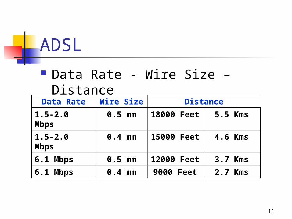
Data Rate - Wire Size – Distance
ADSL
Data Rate Wire Size Distance
1.5-2.0 Mbps
0.5 mm 18000 Feet
5.5 Kms
1.5-2.0 Mbps
0.4 mm 15000 Feet
4.6 Kms
6.1 Mbps 0.5 mm 12000 Feet
3.7 Kms
6.1 Mbps 0.4 mm 9000 Feet 2.7 Kms
12
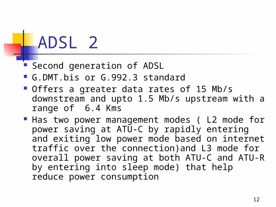
ADSL 2 Second generation of ADSL G.DMT.bis or G.992.3 standard Offers a greater data rates of 15 Mb/s downstream
and upto 1.5 Mb/s upstream with a range of 6.4 Kms
Has two power management modes ( L2 mode for power saving at ATU-C by rapidly entering and exiting low power mode based on internet traffic over the connection)and L3 mode for overall power saving at both ATU-C and ATU-R by entering into sleep mode) that help reduce power consumption
13
ADSL 2…contd. Supports seamless adaptation of
data rate in real time to meet the changing line conditions
Fast start up i.e.Reduced initialization time from 10 secs to 3 secs.
Data rates can be increased by bonding multiple phone lines ( 2 or more copper pairs) together.
14
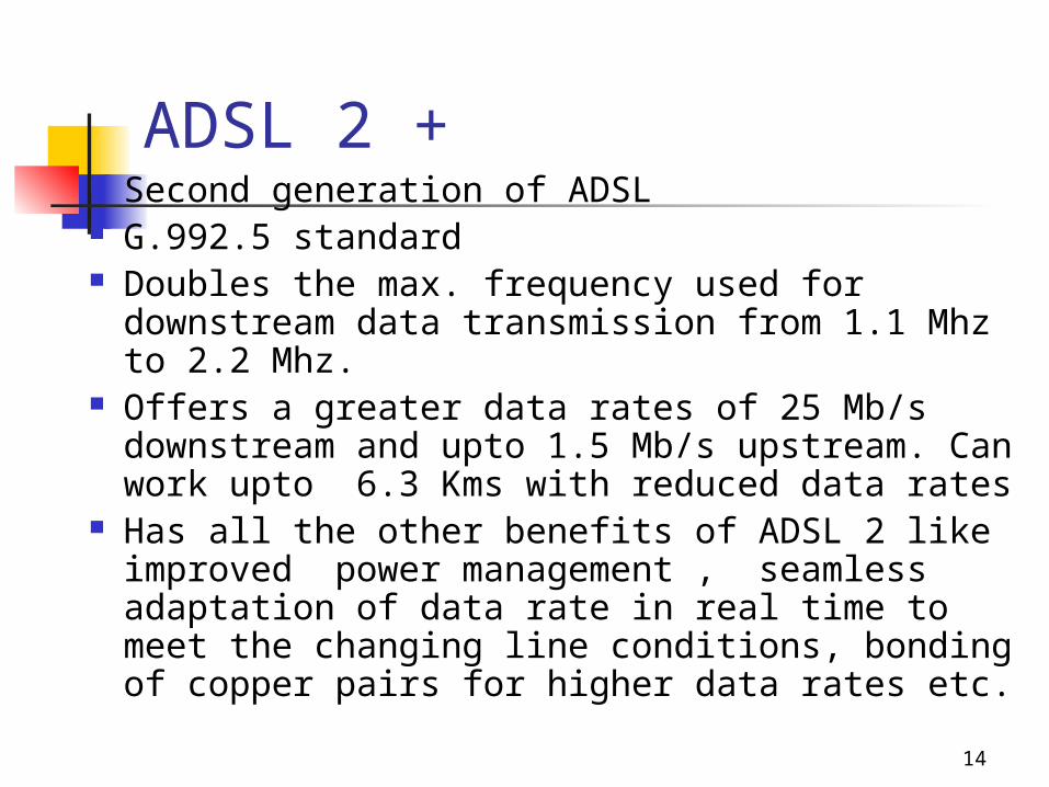
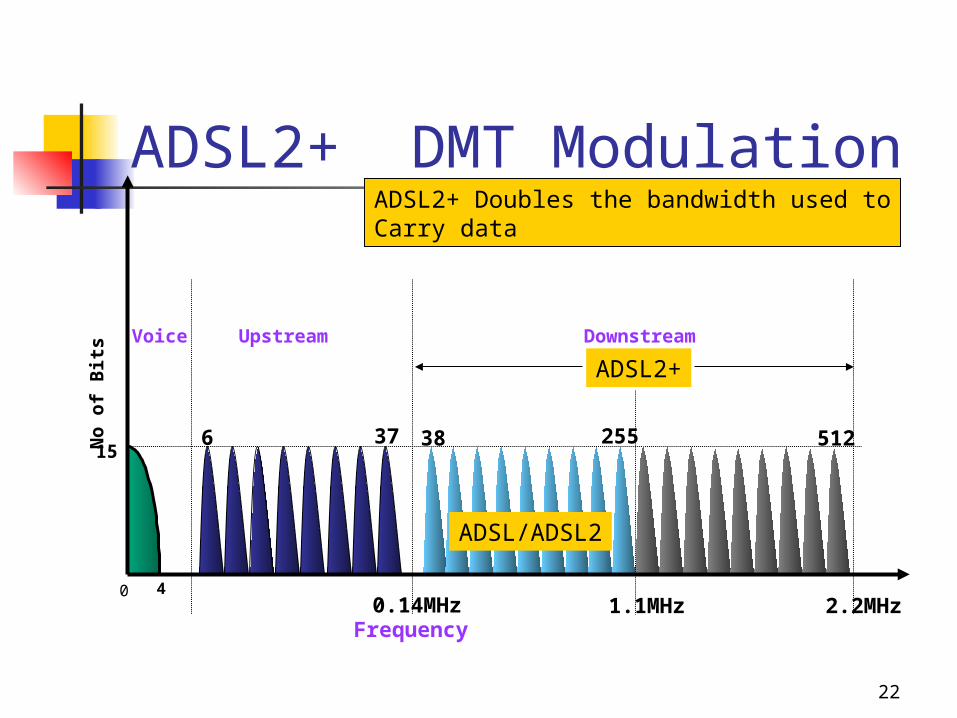
ADSL 2 + Second generation of ADSL G.992.5 standard Doubles the max. frequency used for
downstream data transmission from 1.1 Mhz to 2.2 Mhz.
Offers a greater data rates of 25 Mb/s downstream and upto 1.5 Mb/s upstream. Can work upto 6.3 Kms with reduced data rates
Has all the other benefits of ADSL 2 like improved power management , seamless adaptation of data rate in real time to meet the changing line conditions, bonding of copper pairs for higher data rates etc.
15
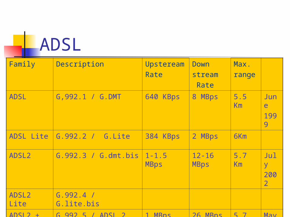
ADSLFamily Description Upsteream
RateDownstream Rate
Max.range
ADSL G,992.1 / G.DMT 640 KBps 8 MBps 5.5 Km
June1999
ADSL Lite G.992.2 / G.Lite 384 KBps 2 MBps 6Km
ADSL2 G.992.3 / G.dmt.bis 1-1.5 MBps 12-16 MBps
5.7 Km
July2002
ADSL2 Lite G.992.4 / G.lite.bis
ADSL2 + G.992.5 / ADSL 2 plus 1 MBps 26 MBps 5.7 Km
May 2003
ADSL2 RE G.992.3 Reach Extended
1MBps 12 MBps 7Km
16
ADSL APPLICATIONS Internet access ( SOHO) LAN Access ( Telecommuting) Distance Learning Tele-medicine Broadcast TV Home shopping Interactive Games Movies
17
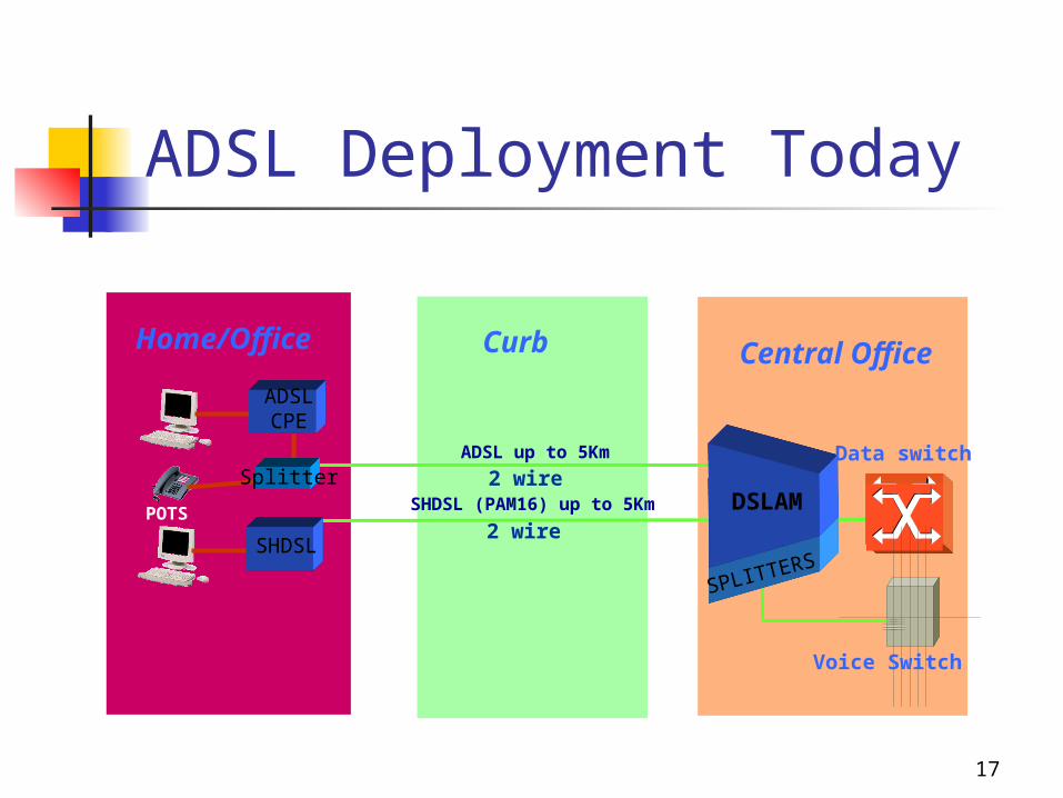
ADSL Deployment Today
SPLITTERS
Central OfficeHome/Office
ADSLCPE
Curb
ADSL up to 5Km
SHDSL (PAM16) up to 5Km
SHDSL
SplitterDSLAM
Data switch
Voice Switch
POTS2 wire
2 wire
18
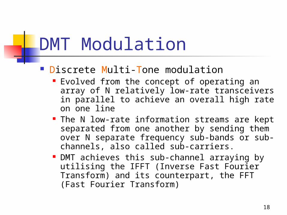
DMT Modulation Discrete Multi-Tone modulation
Evolved from the concept of operating an array of N relatively low-rate transceivers in parallel to achieve an overall high rate on one line
The N low-rate information streams are kept separated from one another by sending them over N separate frequency sub-bands or sub-channels, also called sub-carriers.
DMT achieves this sub-channel arraying by utilising the IFFT (Inverse Fast Fourier Transform) and its counterpart, the FFT (Fast Fourier Transform)
19
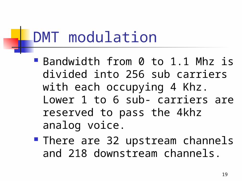
DMT modulation Bandwidth from 0 to 1.1 Mhz is
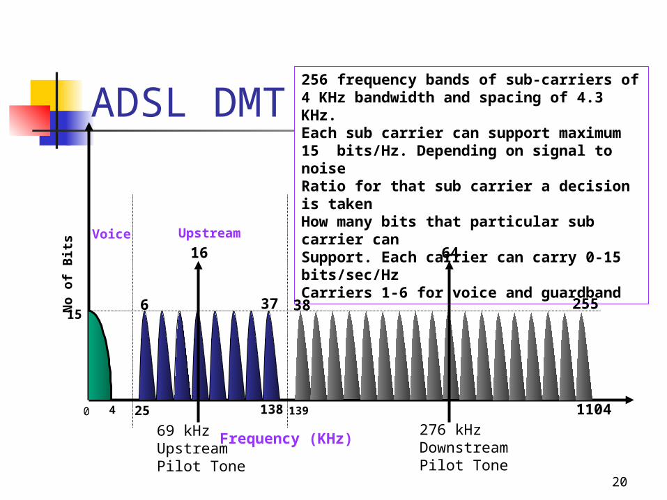
divided into 256 sub carriers with each occupying 4 Khz. Lower 1 to 6 sub- carriers are reserved to pass the 4khz analog voice.
There are 32 upstream channels and 218 downstream channels.
20
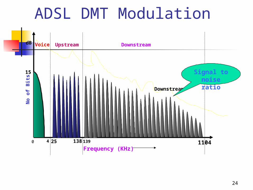
ADSL DMT Modulation
Upstream
Frequency (KHz)
DownstreamVoice
0 4
256 frequency bands of sub-carriers of4 KHz bandwidth and spacing of 4.3 KHz.Each sub carrier can support maximum15 bits/Hz. Depending on signal to noiseRatio for that sub carrier a decision is takenHow many bits that particular sub carrier canSupport. Each carrier can carry 0-15 bits/sec/HzCarriers 1-6 for voice and guardband
25 138 139
No
of
Bit
s
15
1104
6 37
16
69 kHzUpstreamPilot Tone
64
276 kHzDownstreamPilot Tone
38 255
21
Frequency Spectrum of ADSL
The ADSL transmit signal consist of a large number ( up to 256) of sub-carrier located at spacing of 4.3125 Khz.
The channel 0 is for POTS , Channel 1-5 are not used to avoid interference between voice and data.
POTS Channel - Separated by a POTS splitter
Upstream/Downstream channels separated by either FDM using LPF/HPF or a combination of FDM and echo cancellation . Echo cancellation improves the BW through put in the downstream direction
22
ADSL2+ DMT Modulation
Frequency
DownstreamVoice
0 4
No
of
Bit
s
156 37 38 255
ADSL/ADSL2
0.14MHz 1.1MHz 2.2MHz
ADSL2+
ADSL2+ Doubles the bandwidth used toCarry data
512
Upstream
23
ADSL 2/2+ ADSL 2/2+ are further improvement over ADSL
and provide greater download speed and better range.
Due to better modulation efficiency, more download speed is possible.
ADSL 2/2+ can re-synchronize on line at different speed without interrupting the communication if SNR changes due to external interference. This is not possible with ADSL.
When no communication is taking place ADSL2/2+ can go in sleep/power saving mode and come back to live mode automatically when data transmission starts.
24
ADSL DMT Modulation
Upstream DownstreamVoice
0 4 25
Frequency (KHz)138 139
No
of
Bit
s
15
dB
1104
Downstream
Signal to noise ratio
25
Broadband Target
1 Million by December 2005
Another 2 millions by December 2006
Another 3 millions by December 2007
Thus a Total of Six Millions by December 2007
To be Achieved Through NIB-II, Broadband Loop
Carrier, Wi-Fi & Wi-Max, New Tender for five million
Broadband Lines titled “Broadband – Multi Play”
26
Requirement at Customer End
BSNL’s BFone
Computer of minimum configuration, with
10/100 Mbps Ethernet Card
DSL Modem + Splitter
PPPoE software to be loaded in the Client
Broadband Account (Username and Password)
27
Broadband Drivers in BSNL1. Prevent Churn of 35 million Wireline base
• To Competitors, who are churning creamy customers• To Mobile Technologies
2. Additional Source of Revenues• High Speed Internet Access• Triple Play services
ITU Report 2003: For telecommunication companies, broadband offers a route to offset the current slowdown in the industry. In the Republic of Korea, the average revenue per user (ARPU) for a broadband user is up to seven times higher than for a narrowband user.
28
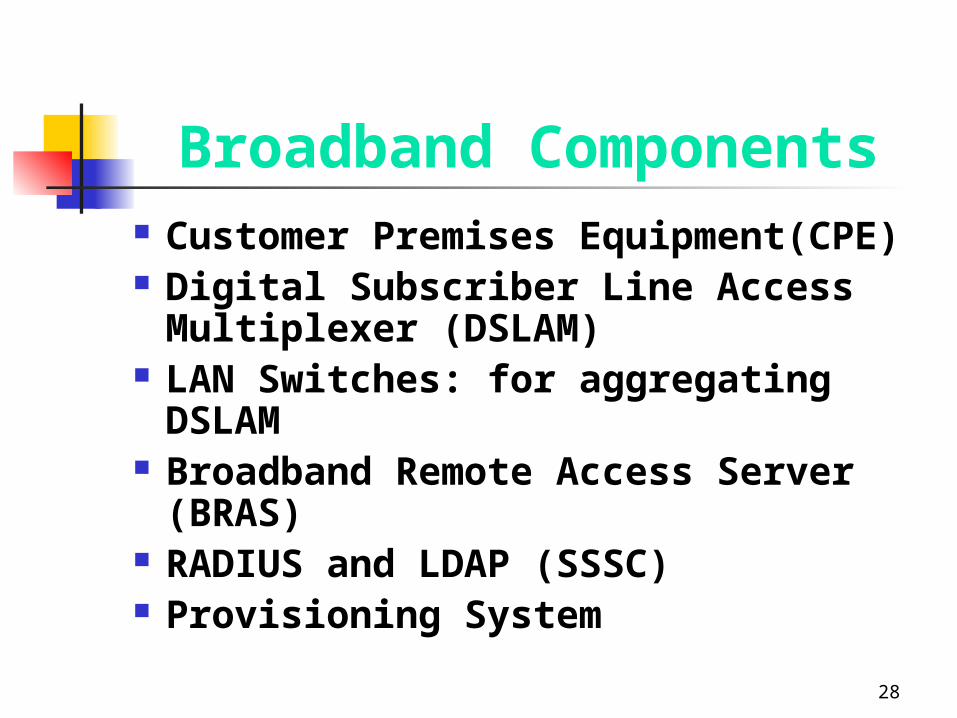
Broadband Components Customer Premises Equipment(CPE) Digital Subscriber Line Access
Multiplexer (DSLAM) LAN Switches: for aggregating DSLAM Broadband Remote Access Server
(BRAS) RADIUS and LDAP (SSSC) Provisioning System
29
Brief Functions of DSL Components
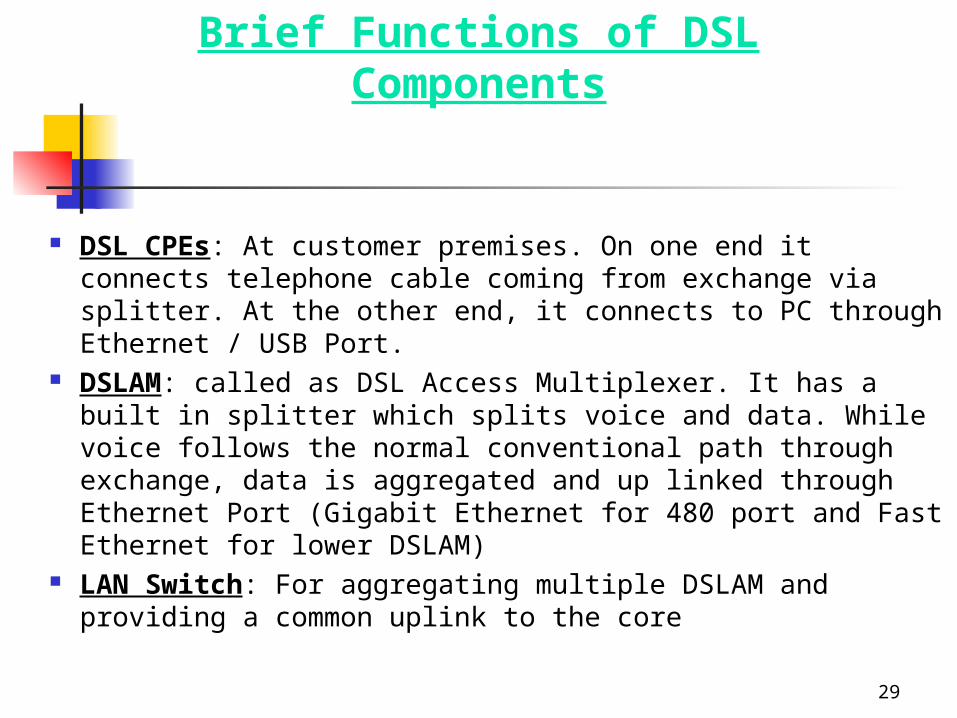
DSL CPEs: At customer premises. On one end it connects telephone cable coming from exchange via splitter. At the other end, it connects to PC through Ethernet / USB Port.
DSLAM: called as DSL Access Multiplexer. It has a built in splitter which splits voice and data. While voice follows the normal conventional path through exchange, data is aggregated and up linked through Ethernet Port (Gigabit Ethernet for 480 port and Fast Ethernet for lower DSLAM)
LAN Switch: For aggregating multiple DSLAM and providing a common uplink to the core
30
Brief Functions of DSL Components….contd.
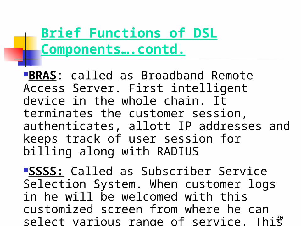
BRAS: called as Broadband Remote Access Server. First intelligent device in the whole chain. It terminates the customer session, authenticates, allott IP addresses and keeps track of user session for billing along with RADIUS
SSSS: Called as Subscriber Service Selection System. When customer logs in he will be welcomed with this customized screen from where he can select various range of service. This provides on demand service without manual intervention
31
Brief Functions of DSL Components…contd.
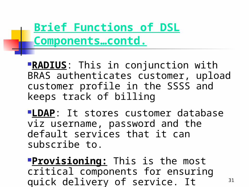
RADIUS: This in conjunction with BRAS authenticates customer, upload customer profile in the SSSS and keeps track of billing
LDAP: It stores customer database viz username, password and the default services that it can subscribe to.
Provisioning: This is the most critical components for ensuring quick delivery of service. It ensures end-to-end provisioning of service right from DSL CPEs to DSLAM to Switch to BRAS to LDAP
32
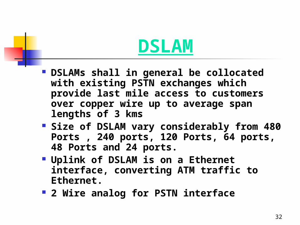
DSLAM DSLAMs shall in general be collocated with
existing PSTN exchanges which provide last mile access to customers over copper wire up to average span lengths of 3 kms
Size of DSLAM vary considerably from 480 Ports , 240 ports, 120 Ports, 64 ports, 48 Ports and 24 ports.
Uplink of DSLAM is on a Ethernet interface, converting ATM traffic to Ethernet.
2 Wire analog for PSTN interface
33
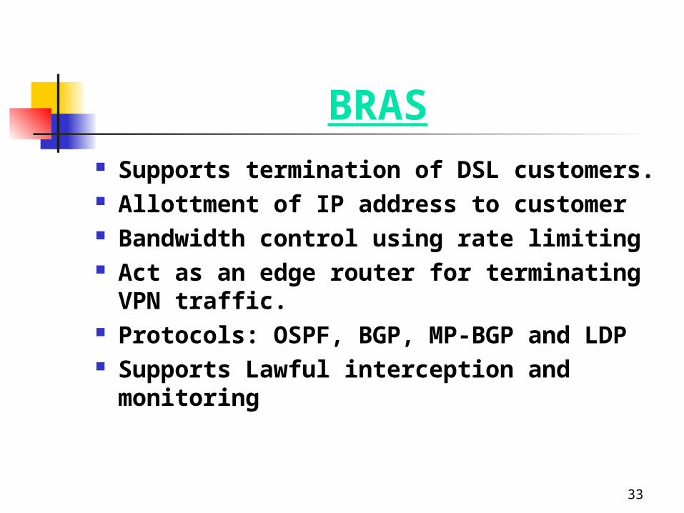
BRAS Supports termination of DSL customers. Allottment of IP address to customer Bandwidth control using rate limiting Act as an edge router for terminating VPN
traffic. Protocols: OSPF, BGP, MP-BGP and LDP Supports Lawful interception and monitoring
34
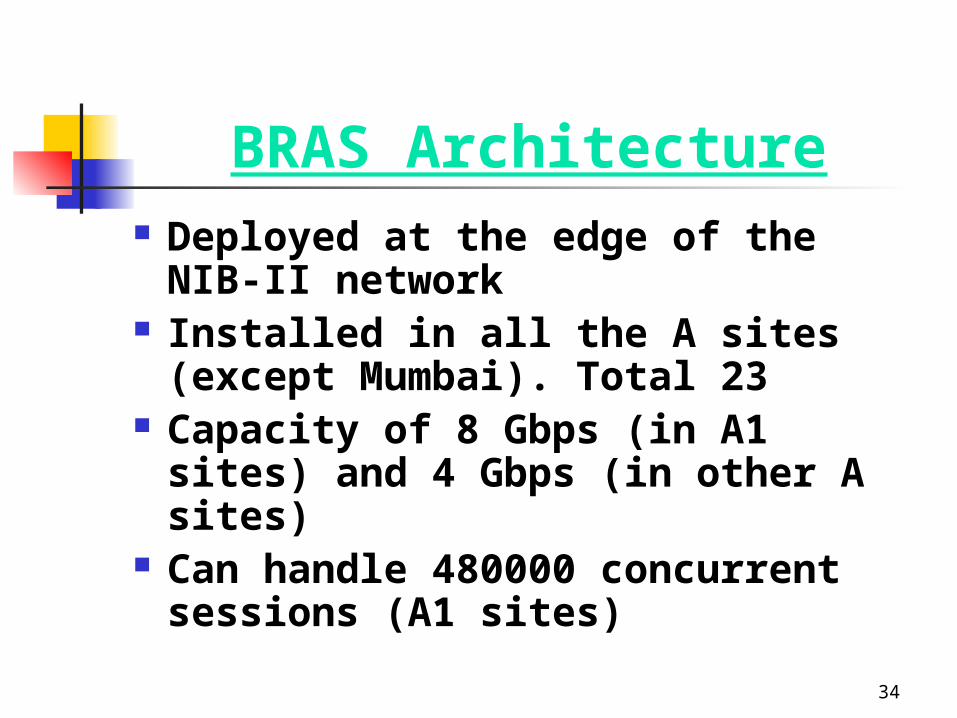
BRAS Architecture Deployed at the edge of the NIB-II
network Installed in all the A sites (except
Mumbai). Total 23 Capacity of 8 Gbps (in A1 sites) and 4
Gbps (in other A sites) Can handle 480000 concurrent sessions
(A1 sites)

CPE
36
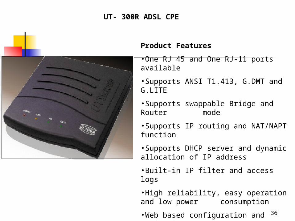
UT- 300R ADSL CPE
Product Features
•One RJ 45 and One RJ-11 ports available
•Supports ANSI T1.413, G.DMT and G.LITE
•Supports swappable Bridge and Router mode
•Supports IP routing and NAT/NAPT function
•Supports DHCP server and dynamic allocation of IP address
•Built-in IP filter and access logs
•High reliability, easy operation and low power consumption
•Web based configuration and monitoring
•Interoperable with other DSLAM
37
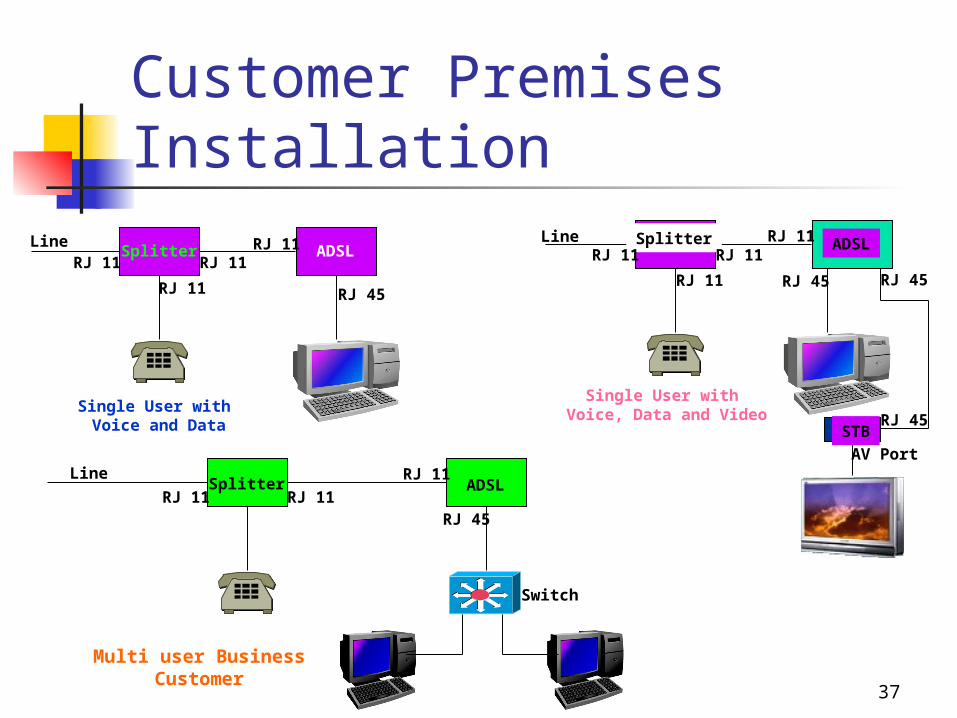
Customer Premises Installation
Splitter ADSLRJ 11 RJ 11
RJ 11
RJ 11
RJ 45
Line
Single User with Voice and Data
Splitter ADSL
STB
RJ 11 RJ 11
RJ 11 RJ 45 RJ 45
RJ 45
AV Port
Single User with Voice, Data and Video
Line RJ 11
Splitter ADSL
Switch
Multi user BusinessCustomer
Line
RJ 11 RJ 11
RJ 11
RJ 45
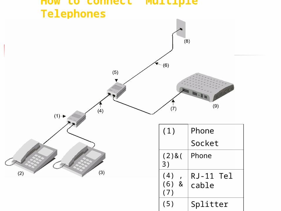
How to connect Multiple Telephones
(1) Phone
Socket (2)&(3)
Phone
(4) ,(6) & (7)
RJ-11 Tel cable
(5) Splitter
(8) Phone Jack
39
highpassfilter
LINEDSL
lowpassfilter
TELE
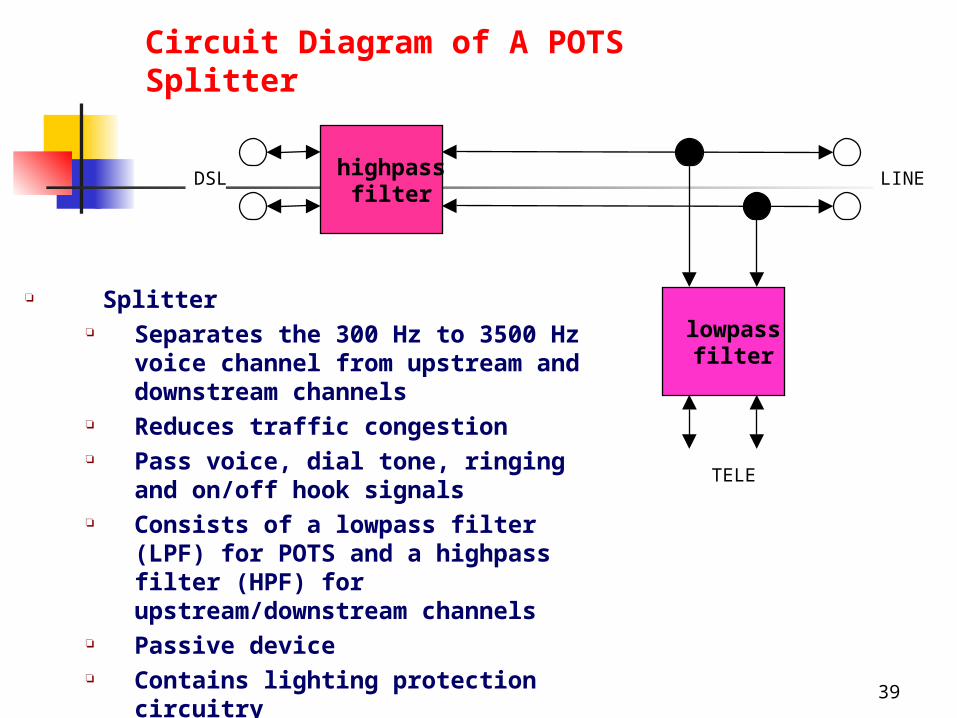
Circuit Diagram of A POTS Splitter
Splitter Separates the 300 Hz to 3500 Hz
voice channel from upstream and downstream channels
Reduces traffic congestion Pass voice, dial tone, ringing and
on/off hook signals Consists of a lowpass filter (LPF)
for POTS and a highpass filter (HPF) for upstream/downstream channels
Passive device Contains lighting protection
circuitry
40
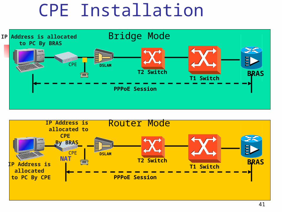
CPE Installation CPE(ADSL MODEM) can be utilized in two
different ways 1. Transparent Bridge – In this mode we need to
configure PPPoE in the customer’s PC and modem simply passes ethernet frames from one side to other side in transparent fashion. Customer’s PC authenticates itself with BRAS
2. Router Mode- In this mode PPPoE is configured in modem. Modem authenticates itself to BRAS and gets IP address. Modem provides different address from its DHCP server to PC. Modem also performs the NAT function in this mode.
41
CPE Installation
BRASCPE
PPPoE Session
T2 SwitchT1 Switch
BRASCPE
PPPoE Session
T2 SwitchT1 Switch
Bridge Mode
DSLAM
IP Address is allocated to PC By BRAS
Router ModeIP Address is allocated to CPE
By BRAS
IP Address is allocated
to PC By CPE
NATDSLA
M
42
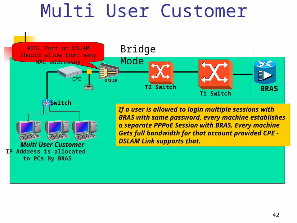
Multi User Customer
BRASCPE
T2 SwitchT1 Switch
Bridge Mode
DSLAM
IP Address is allocated to PCs By BRAS
Multi User Customer
If a user is allowed to login multiple sessions withBRAS with same password, every machine establishes a separate PPPoE Session with BRAS. Every machineGets full bandwidth for that account provided CPE -DSLAM Link supports that.
Switch
ADSL Port on DSLAM Should allow that many MAC addresses
43
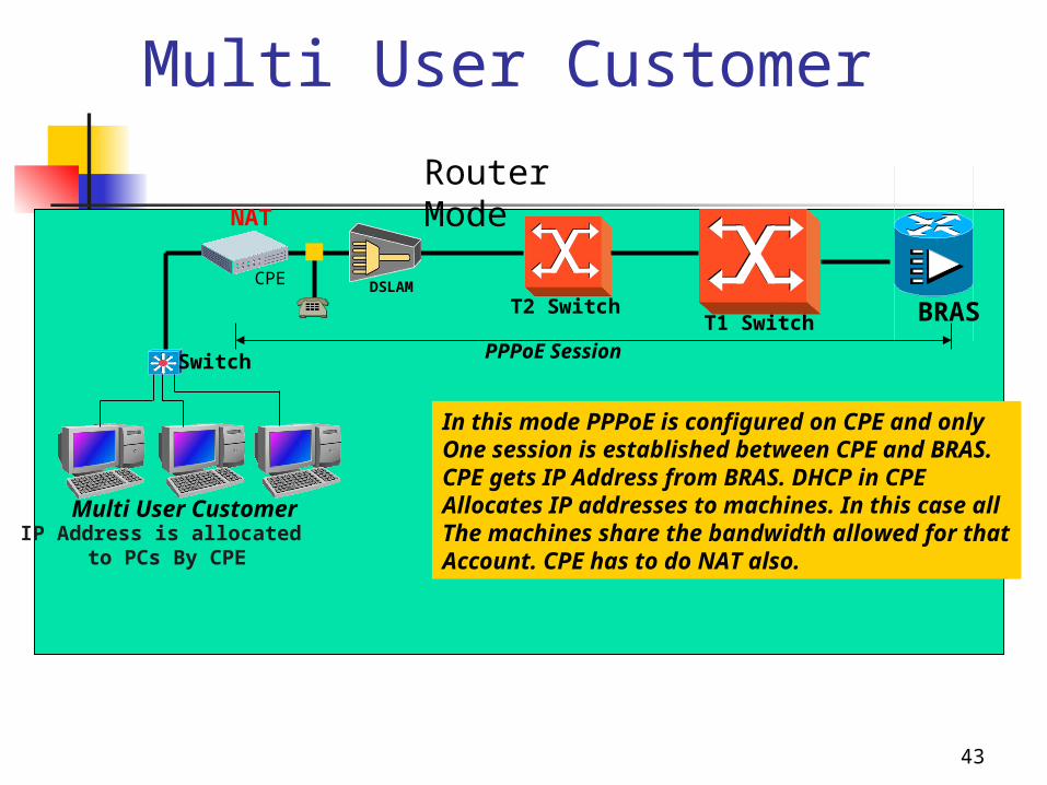
Multi User Customer
BRASCPE
T2 SwitchT1 Switch
Router Mode
DSLAM
IP Address is allocated to PCs By CPE
Multi User Customer
In this mode PPPoE is configured on CPE and onlyOne session is established between CPE and BRAS.CPE gets IP Address from BRAS. DHCP in CPE Allocates IP addresses to machines. In this case allThe machines share the bandwidth allowed for thatAccount. CPE has to do NAT also.
Switch PPPoE Session
NAT

DSLAM
45
46
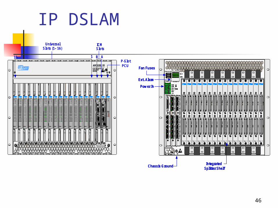
IP DSLAM
P-SlotPCU
ICMSlots
UniversalSlots (1 – 16)
116 B A
Fan Fuses
Power In
Chassis Ground
Ext. Alarm
Integrated Splitter Shelf
Fan Fuses
Power In
Chassis Ground
Ext. Alarm
Integrated Splitter Shelf
47
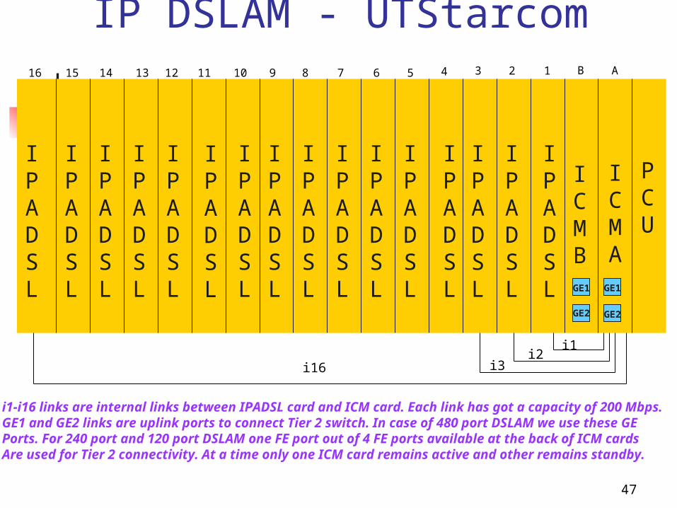
IP DSLAM - UTStarcomAB12345678910111213141516
PCU
ICMA
ICMB
IPADSL
IPADSL
IPADSL
IPADSL
IPADSL
IPADSL
IPADSL
IPADSL
IPADSL
IPADSL
IPADSL
IPADSL
IPADSL
IPADSL
IPADSL
IPADSL
i1i2
i3i16
GE1GE1
GE2 GE2
i1-i16 links are internal links between IPADSL card and ICM card. Each link has got a capacity of 200 Mbps.GE1 and GE2 links are uplink ports to connect Tier 2 switch. In case of 480 port DSLAM we use these GE Ports. For 240 port and 120 port DSLAM one FE port out of 4 FE ports available at the back of ICM cardsAre used for Tier 2 connectivity. At a time only one ICM card remains active and other remains standby.
48
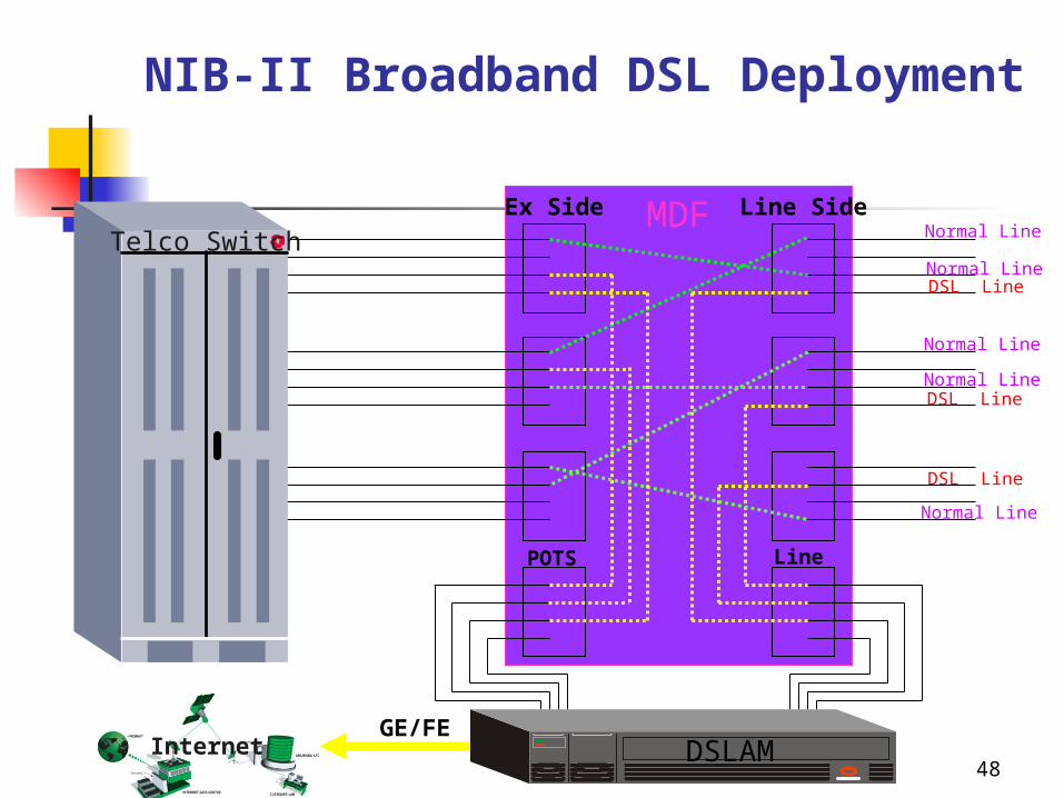
NIB-II Broadband DSL Deployment
Normal Line
Ex Side Line SideMDF
InternetGE/FE
Normal Line
DSL Line
Normal Line
Normal Line
Normal Line
DSL Line
DSL Line
Telco Switch
DSLAM
POTS Line
49
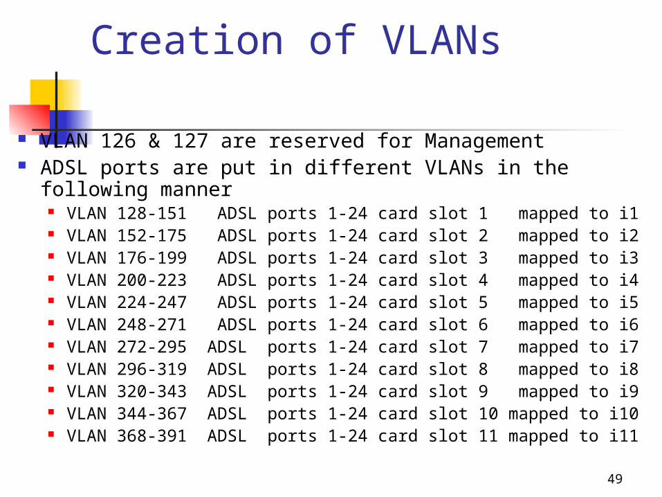
Creation of VLANs
VLAN 126 & 127 are reserved for Management ADSL ports are put in different VLANs in the following
manner VLAN 128-151 ADSL ports 1-24 card slot 1 mapped to i1 VLAN 152-175 ADSL ports 1-24 card slot 2 mapped to i2 VLAN 176-199 ADSL ports 1-24 card slot 3 mapped to i3 VLAN 200-223 ADSL ports 1-24 card slot 4 mapped to i4 VLAN 224-247 ADSL ports 1-24 card slot 5 mapped to i5 VLAN 248-271 ADSL ports 1-24 card slot 6 mapped to i6 VLAN 272-295 ADSL ports 1-24 card slot 7 mapped to i7 VLAN 296-319 ADSL ports 1-24 card slot 8 mapped to i8 VLAN 320-343 ADSL ports 1-24 card slot 9 mapped to i9 VLAN 344-367 ADSL ports 1-24 card slot 10 mapped to i10 VLAN 368-391 ADSL ports 1-24 card slot 11 mapped to i11
50
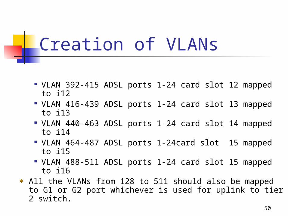
Creation of VLANs
VLAN 392-415 ADSL ports 1-24 card slot 12 mapped to i12 VLAN 416-439 ADSL ports 1-24 card slot 13 mapped to i13 VLAN 440-463 ADSL ports 1-24 card slot 14 mapped to i14 VLAN 464-487 ADSL ports 1-24card slot 15 mapped to i15 VLAN 488-511 ADSL ports 1-24 card slot 15 mapped to i16
All the VLANs from 128 to 511 should also be mapped to G1 or G2 port whichever is used for uplink to tier 2 switch.
51
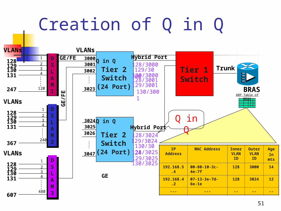
Creation of Q in Q
128129130131
VLANs
128129130131
VLANs
128129130131
VLANs
300030013002
BRAS
Tier 2Switch
(24 Port)
Q in Q
VLANsHybrid Port
Tier 1Switch
128/3000129/3000130/3000128/3001129/3001
302430253026
Q in Q
128/3024129/3024130/3024128/3025129/3025130/3025
3023
3047
Tier 2Switch
(24 Port)
Trunk
Hybrid Port
DSLAM1
DSLAM2
DSLAM3
1
234
120
1
234
240
1
234
480
GE/FEG
E/F
E
GE
367
607
247 130/3001ARP Table of BRAS
IP Address
MAC Address Inner VLAN
ID
Outer VLAN
ID
AgeIn
mts
192.168.5.4
00-80-10-3c-4e-7f
128 3000 14
192.168.4.2
07-13-3e-7d-6e-1e
128 3024 12
--- --- -- -- --
Q in Q
52
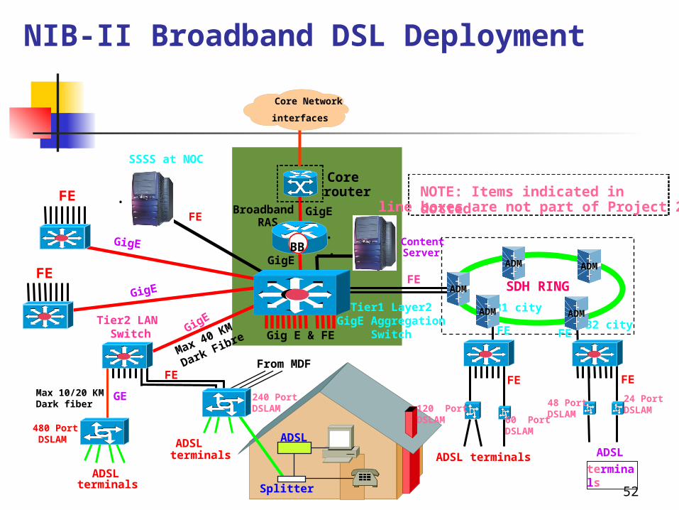
NIB-II Broadband DSL Deployment
Broadband RAS
480 PortDSLAM
SDH RINGGigE
GigE
GigE
Tier2 LAN Switch
NOTE: Items indicated in dottedline boxes are not part of Project 2.2
Corerouter
Gig E & FE
FE FE
FE
B1 city
ADSL terminals
ADSL terminals ADSL
terminals
FE
GE
ADSL terminals
GigE
FE
GigE
24 PortDSLAM
FE
BB•
•ContentServer
•
SSSS at NOC
FE
B2 city
Core Network
interfaces
Splitter
ADSL
From MDFMax 40 KM
Dark Fibre
Max 10/20 KMDark fiber
Tier1 Layer2GigE Aggregation
Switch
ADMADM
ADM
ADM ADM
48 PortDSLAM
60 PortDSLAM
120 PortDSLAM
FE FE
240 PortDSLAM
53
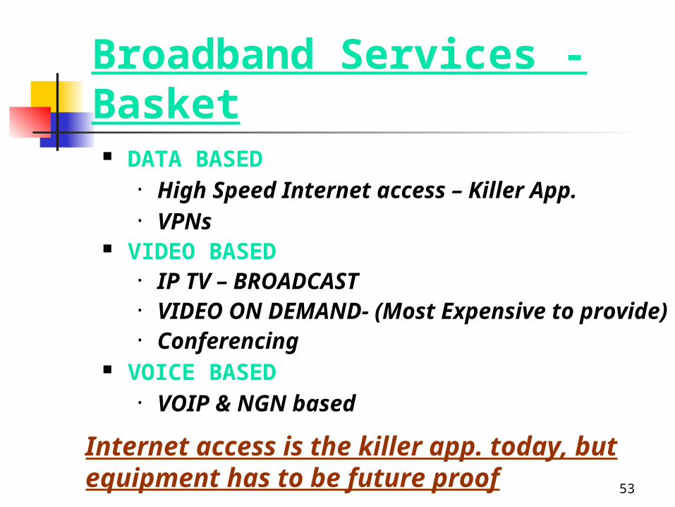
Broadband Services - Basket DATA BASED
• High Speed Internet access – Killer App.• VPNs
VIDEO BASED• IP TV – BROADCAST• VIDEO ON DEMAND- (Most Expensive to provide)• Conferencing
VOICE BASED• VOIP & NGN based
Internet access is the killer app. today, but equipment has to be future proof

54
Thanks !