Embed Size (px)
Citation preview
ESI (Estech Systems, Inc.) • 3701 E. Plano Parkway • Plano, TX 75074 • 800 374-0422 • fax: 972 422-9705 0450-1076 e-mail: [email protected] • Web: www.esi-estech.com Rev. C
Contents
Advantage summary ........................................ 2
Hardware description ....................................... 3
Features at a glance ......................................... 4
IP telecommunications capabilities ................ 8
Migration capability ........................................ 12
System programming .................................... 12
Specifications and requirements .................. 13
Glossary ........................................................... 16
Color collaterals available
Family brochure: ESI # 0450-1052. System spec sheets: ESI #s 0450-1055 (ESI-1000); 0450-1056 (ESI-600); 0450-1054 (ESI-200); 0450-1053 (ESI-100); 0450-1148 (ESI-50); and 0450-1149 (ESI-50L). All downloadable from www.esi-estech.com/brochures. All ESI documents mentioned herein are available from www.esiresellers.com (password required).
Advanced digital and IP communications servers
ESI Communications Servers represent an innovative approach to digital and IP communications. The science behind the switch is sophisticated in its simplicity: Design a platform with the flexibility to support digital functionality with the ability to be configured as a purely IP-based communications system. It’s ideal for any business that wants the familiarity
of digital telephony, the benefits of full IP-to-the-desktop, or anything in-between.
Introduction
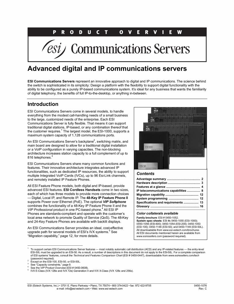
ESI Communications Servers come in several models, to handle everything from the modest call-handling needs of a small business
to the large, customized needs of the enterprise. Each ESI Communications Server is fully flexible. That means it can support traditional digital stations, IP-based, or any combination thereof that the customer requires.
1 The largest model, the ESI-1000, supports a
maximum system capacity of 1,128 communications ports.
An ESI Communications Server’s backplane2, switching matrix, and
main board are designed to allow for a traditional digital installation or a VoIP configuration in varying capacities. The non-blocking architecture increases station capacity to a full complement of up to
816 telephones.3
ESI Communications Servers share many common functions and features. Their innovative architecture integrates advanced IP functionalities, such as dedicated IP resources, the ability to support multiple Integrated VoIP Cards (IVCs), up to 96 Esi-Link channels, and remotely installed IP Feature Phones.
All ESI Feature Phone models, both digital and IP-based, provide advanced ESI features. ESI Cordless Handsets come in two sizes,
each of which has three models to provide more connection choices — Digital, Local IP, and Remote IP. The 48-Key IP Feature Phone II supports Power over Ethernet (PoE). The optional VIP Softphone combines the functionality of a 48-Key IP Feature Phone II and the VIP Professional product in one PC-based phone.
4 All ESI IP
Phones are standards-compliant and operate with the customer’s local area network to promote Quality of Service (QoS). The 48-Key and 24-Key Feature Phones are available with backlit displays.
An ESI Communications Server provides an ideal, cost-effective upgrade path for several models of ESI’s IVX systems.
5 See
“Migration capability,” page 12, for more details.
1 To support certain ESI Communications Server features — most notably automatic call distribution (ACD) and any IP-related features — the entry-level
ESI-50L must be upgraded to an ESI-50. As a result, a number of descriptions in this document do not apply to the ESI-50L. For a complete comparison of ESI systems’ features, consult the Technical and Features Comparison Chart (ESI # 0450-0447), downloadable from www.esiresellers.com/tech (password required).
2 Except on the ESI-100, ESI-50, or ESI-50L.
3 See “Capacity constraints,” page 9.
4 See the VIP Product Overview (ESI # 0450-0608).
5 IVX E-Class (IVX 128e and IVX 72e) Generation II and IVX X-Class (IVX 128x and 256x).
ESI Communications Servers Product Overview
2
Advantage summary
Note: Maximum capacities shown.
Capacities
System
ESI-1000
ESI-600
ESI-200
ESI-100
ESI- 50
ESI- 50L
System ports 1,128 624 300 108 87 48
Trunk ports 240 168 84 42 35 16
DLCs (for T1/PRI) 10 6 3 1 11 0
IVCs 34 17 8 3 12 0
Station ports3 816 408 192 84 52 40
IP stations 816 408 192 72 12 0
Digital stations 504 336 168 48 32 32
Analog stations 384 188 56 28 8 8
Esi-Link cards (up to 24 Esi-Link chs./card)
4
4 2 1 1 12 0
Conference ports
5
64 64 24 16 16 16
Voice mail
ESI-1000
ESI-600
ESI-200
ESI-100
ESI- 50
ESI- 50L
On-board integrated auto-attendant/ voice mail chs.
128 32 16 or 24
8 6 6
Total voice mailboxes
1,941 1,481 1,229 1,121 258 246
User 816 408 192 84 52 40
Info./guest 1,000 1,000 1,000 1,000 190 190
Group/ Max. members
64/200 32/64 16/48 16/32 16/32 16/32
“Special- purpose”
61 41 21 21 21 21
Voice storage (hrs.)
6
1,200 1,200 140
or 600 140
15 or 60
15
1 The ESI-50 doesn’t support T1.
2 The ESI-50 has a built-in IVC; it accepts no additional IVCs. The
built-in IVC supports 12 local IP channels, eight remote IP channels, or a combination thereof whose total can’t exceed 12 IP channels.
3 See “Capacity constraints,” page 9.
4 Esi-Link channels are allocated to “reserved” ports; i.e.,
Esi-Link channels don’t reduce CO or station capacity. 5 Dynamic assignment allows for unlimited combinations up to the
maximum of 16 parties per conference — e.g., 21 three-member conferences, or four four-member conferences in combination with two eight-member conferences. Achieves best audio performance when using digital trunks.
6 The differing quantities for the ESI-200 and ESI-50 reflect those
models’ Memory Module choices.
Standard features
• Account codes
• Automatic call distribution7
• Built-in Network Services Processor (NSP)
• Caller ID key
• Distinctive ring for trunks
• Enhanced Caller ID
• Esi-Dex integrated directories
• Fax tone detection
• Flexible numbering plans
• Recording of calls
• Shared-office tenanting7 (maximum of eight tenants)
• Station redial and callback
Optional applications • ESI Presence Management
• ESI Bluetooth Voice Integration
• Mirrored Memory Module (M3)8
• Esi-Link IP private networking7
• Power over Ethernet support for IP Feature Phone II7
• Dual-configuration 48-key IP Feature Phone II7
(supports local and remote installations)
• Digital, Local IP7, and Remote IP
7 Cordless Handsets
• Third-party SIP9 stations
7
• VIP (Visually Integrated Phone) and VIP Professional
• VIP ACD Supervisor7 and VIP ACD Agent
7
• VIP PC Attendant Console
• VIP Softphone7
• ESI Personal Programmer
7 Not applicable to the ESI-50L.
8 Standard on the ESI-1000; not available on the ESI-100, ESI-50,
or ESI-50L. 9 See “IP telecommunications capabilities,” page 8.
ESI Communications Servers Product Overview
3
Hardware description
System configurations
ESI-1000, ESI-600, ESI-200
The largest-capacity ESI Communications Servers — the ESI-1000, ESI-600, and ESI-200 — are compact, rack-mounted systems. The maximum configuration of each consists of one Base Cabinet and the following number of Expansion Cabinets (maximums shown):
ESI-1000 ESI-600 ESI-200
Expansion Cabinets 5 3 1
The ESI-200’s Expansion Cabinet is unique to that model, while the ESI-1000 and ESI-600 share the same Expansion Cabinet. If desired, the cabinets may be wall-mounted, but rack-mounting is the preferred
method of installation.
ESI-100, ESI-50, ESI-50L
The ESI-100, ESI-50, and ESI-50L each consists of a compact Base Cabinet with the same form factor of ESI’s long-popular IVX products. Each accepts one Expansion Cabinet through a “piggyback” method. Typically, these systems’ cabinets are wall-mounted.
Processing
Processing power is provided by a Motorola® ColdFire®
commercial-grade microprocessor, designed specifically for 24/7 operation. This device houses SDRAM for stored program control. It also interfaces with 3 on-board DSPs that manage the HDD controller, inter-card communications, and telephony services, ensuring rapid, dependable communications among all system resources: trunks, digital stations, and IP Phones. The ColdFire processor’s model, speed, and
SDRAM capacity vary by ESI Communications Server model:
ESI-1000
ESI- 600
ESI- 200
ESI- 100
ESI- 50
ESI- 50L
Processor model
MCF-5407
MCF-5407
MCF-5407
MCF-5272
MCF-5272
MCF-5272
Speed (MHz) 54 54 54 66 66 66
SDRAM (MB) 128 128 64 32 32 32
Power provisions
Each cabinet is powered by its own power supply. In rack-mounted installations, a power shelf is available that provides AC connection for each of the cabinet power supplies. This reduces the number of AC power outlets needed to one, instead of one per power supply. When a UPS system is installed, only one connection
to the UPS must be made from the system, rather than one from each of the cabinets. The power shelf is separately fused to protect system components against erratic power fluctuations.
Each cabinet has a grounding lug and solder terminal for the connection of a ground wire. It is highly recommended that all cabinets be grounded to a common grounding point by “pig-tailing” the ground wire from one cabinet to the one below it.
Cabinet connection
ESI-1000, ESI-600, ESI-200
Connection between cabinets on these models is made through a SCSI (Small Computer System Interface)
cable, which is shipped with each Expansion Cabinet. This SCSI cable extends the motherboard from cabinet to cabinet, creating a common backplane.
ESI-100, ESI-50, ESI-50L
Connection between cabinets on these models is made through a ribbon cable that connects between port cards in adjoining “piggybacked” cabinets.
Main board
The Main Board houses a built-in Network Services
Processor (NSP) for all applications requiring direct connection of the ESI Communications Server to the customer’s local area network. These applications include SMDR, system programming via TCP/IP, and ESI options such as the VIP family of software applications
1 and ESI Presence Management’s ESI
TimeLine payroll data collection option.
The M3 (Mirrored Memory Module)2 provides a full,
real-time back-up of system programming data and voice messages. The M3 is designed with RAID 1 redundancy technology. If the main hard disk drive controller senses a drive failure, it will automatically switch to the mirrored drive and continue to run. This switch of drives initiates an audible alarm with a visual LED indication on the front panel of the Base Cabinet.
Fully flexible platform
Each ESI Communications Server offers impressive
expansion capabilities. On each model other than the ESI-50 and ESI-50L, each available card slot accepts either digital or IP cards, to allow the customer maximum flexibility in configuration. The ESI-50 comes with one built-in IVC (which is its maximum capacity for IVCs); and the ESI-50 and ESI-50L each have the capabilities of a 482 port card (see “Port cards supported,” page 14) on the main board.
For each ESI Communications Server’s capacities, refer to “Advantage summary,” page 2.
3
1 The ESI-50L doesn’t support VIP ACD Supervisor, VIP ACD Agent,
or VIP Softphone. 2 Standard on the ESI-1000; optional on the ESI-600 and ESI-200; not
available for the ESI-100, ESI-50, or ESI-50L. 3 See also “Capacity constraints,” page 9.
ESI Communications Servers Product Overview
4
Features at a glance
Note: For system-by-system details on quantities for features described in this section, see the “Advantage summary” on page 2.
An ESI Communications Server combines the power of a PBX with the ease of use for which every ESI phone system is renowned. Its feature set, capacities and scalability ensure:
• Availability of all features1, functionalities and tools
ESI offers to increase the productivity of an enterprise.
• Expansion ability to meet shifting demands of business growth.
Integrated voice mail — A full complement of practical, easy-to-use voice mail features is standard
on every ESI Communications Server:
• In addition to its call processing ports, an ESI Communications Server is configured with built-in voice mail channels. There is no need to balance voice mail needs at the expense of a customer’s call-handling requirements.
• Voice mail and other message storage are recorded at the highest grade of voice quality (64-Kbit/ second sampling).
• Substantial voice message storage ensures ample capacity for all mailbox users, including the needs of users enabled with the optional auto-record feature.
• Support for 12 message-on-hold recordings:
– Three pre-recorded tracks.
– Nine customizable recordings.
• New-message notification can be delivered off-premises to a phone or pager.
• Leaving messages for up to 65 mailboxes at once is easy, using ESI’s unique Quick Groups
™ feature.
• ESI’s Quick Move™
function enables conversations to be recorded directly into another user’s mailbox. At the mailbox user’s option, urgent messages can be treated with priority and delivered first, instead of on a “first in-first out” basis.
• Several different mailbox types — including group, broadcast, information, cascade paging, Q & A, and guest mailboxes — support a wide range of customer applications.
• Callers forwarded to user or guest voice mailboxes can reach the called individual at a designated off-premises “reach me” number.
1 See the Technical and Features Comparison Chart (ESI # 0450-0447)
for specific feature availability and capacities for all ESI Communications Servers.
• Each user mailbox is equipped with a Message Recycle Bin that remembers, and can restore, the 10 most recently deleted messages.
• One or more stations may have a programmable Virtual Mailbox Key
™ on their stations to allow
easy monitoring of a second mailbox.
Auto attendant — An ESI Communications Server
provides rich, comprehensive auto attendant features:
• 100 branches (six levels deep) to permit the design of a more natural, caller-friendly answering environment, including a company directory.
• Virtually unlimited call routing, including off-premises transfer.
• Three-character dial-by-name for callers to search through the auto attendant directory and all Esi-Dex directories to find the desired name.
Flexible conference channels — Each ESI Communications Server reserves channels for conferencing. These can be dynamically
2 connected in
multi-party conversations up to 16 channels per conference. Any combination of conference channels
may be joined together, as long as the originating party is an ESI Communications Server user. All channels reserved for conferencing are dynamically balanced for optimum audio performance.
Shared-office tenanting3 — Businesses can share a
common telephone system while maintaining a true
separation of various system resources, facilities, and features:
• Private or dedicated outside lines by line groups.
• Distinctive incoming ring assignments per tenant.
• Separate auto attendant greetings and branches.
• Individual “dial 0” operators, music-on-hold sources, and paging zones.
• Unique day/night modes of operation.
2 Dynamic assignment of the conference channels allows for any
combination of members (up to the maximum of 16) per conference — e.g., on the ESI-1000 or ESI-600, ten four-member conferences and three eight-member conferences can take place simultaneously.
3 Not supported by the ESI-50L.
ESI Communications Servers Product Overview
5
Enhanced automatic call distribution1 — Manage
call overload and increase customer satisfaction with ESI’s standard call center feature.
2 ACD ensures that:
• Calls are prioritized and routed within designated departments for quickest possible call handling.
• Managers and agents receive up-to-the-second information on queues and wait times via any 48-Key or 24-Key Feature Phone display.
• Supervisors have access to agents’ ACD call activity to more effectively evaluate call traffic and agent performance.
• A separate hold recall timer is provided for ACD agents, further ensuring that customer care is enhanced.
• Agents may log into two separate ACD departments simultaneously, with departmental prioritization.
Verbal User Guide™ — Users have instant access to assistance in operating their ESI phones and voice mailboxes.
3 By pressing the HELP key, the user is
presented with extensive spoken and displayed prompts to assist with phone operation, voice mail features, programming instructions, and more. System Administrators and Reseller technicians can also use the Verbal User Guide to prompt them through
infrequently used programming changes.
Esi-Dex™ — Locating and calling hundreds of frequently dialed phone numbers is easy when using ESI’s Esi-Dex speed-dialing feature. Up to four separate lists (“Dexes”) are available:
• Station Dex — All extensions within the system.
• Personal Dex — All speed-dial entries programmed by each individual user.
• System Dex — All speed-dial entries stored system-wide.
• Location Dex (available when Esi-Link is installed) — Lists all dial access codes associated with each location within an Esi-Link private network.
Saving numbers to the Personal Dex is just as easy. When Caller ID is presented with an incoming call or a voice mail message, one touch of the ESI-DEX key
stores the provided number for future use.
1 Not supported by the ESI-50L.
2 The optional VIP ACD application allows even easier and more
substantial management of ACD operations. See the VIP ACD Product Overview (ESI # 0450-0988).
3 Not available from an ESI Cordless Handset.
Intelligent Call Forwarding™ — Users of an ESI Communications Server equipped with one or more PRI
1 digital trunk circuits have access to this unique
feature. Users who forward their calls off-premises are able to view the original Caller ID data of incoming
forwarded calls.4
Personal Caller ID5 — For situations in which the
company’s leading number identification data may not be the appropriate Caller ID for individual station users, an ESI Communications Server makes it possible to define a different Caller ID number to be associated with, and sent for, each individual user. This feature provides E-911 support.
6
Flexible numbering
Flexible numbering provides the means to assign extensions, mailboxes, and department numbers based on specific customer requirements. An ESI Communications Server’s flexible numbering is
separated into three parts:
1. Selecting a numbering plan template;
2. Reassigning ranges of extensions, speed-dial numbers, and guest mailboxes (if needed);
3. Reassigning numbers for individual extensions, speed-dial numbers, guest mailboxes, and departments.
Selectable numbering plans
The selectable numbering plan template is the basis for
flexible numbering assignment. When a numbering template is selected, all extensions, mailboxes, departments, and other system features are automatically assigned with the numbering plan of that template. Choosing the template that is closest to the customer’s existing configuration greatly simplifies, or even eliminates the need for, number reassignment.
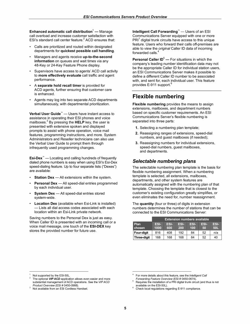
The quantity (four or three) of digits in extension
numbers determines the number of stations that can be connected to the ESI Communications Server:
Extension numbers available
Plan chosen
ESI-1000
ESI-600
ESI-200
ESI-100
ESI- 50
ESI- 50L
Four-digit 816 408 192 84 52 n/a
Three-digit 168 168 168 84 52 40
4 For more details about this feature, see the Intelligent Call
Forwarding Feature Overview (ESI # 0450-0674). 5 Requires the installation of a PRI digital trunk circuit (and thus is not
available on the ESI-50L). 6 Check local regulations regarding E-911 compliance.
ESI Communications Servers Product Overview
6
Range reassignment
Flexible number range assignment is used to change the numbers of a block, or range, of extensions, speed-dial numbers, guest mailboxes, or departments.
The flexible numbering plan is very useful in matching station extension numbers with blocks of DID numbers
assigned by the telephone company. If a customer already has an extension number directory assigned and does not want to change it, the flexible dialing plan will also accommodate this request.
Number reassignment
The number reassignment function will let the Installer assign new — or reassign existing — numbers for individual extensions, speed-dial numbers, departments, and mailboxes.
Station move
Station move is used by the Installer or System Administrator to move, or exchange, extension numbers and other station information between extensions of the same station type.
1 Programmable
feature keys, personal greetings, voice mail messages, and other station information are automatically and instantly exchanged between the two stations when station move is done.
The Installer can use a separate programming function for flexible reassignment of station and department numbers through ESI System Programmer.
Esi-Link and selectable numbering
In an Esi-Link network, certain ESI Communications Server selectable numbering templates can be incompatible with some ESI systems. For additional details about these compatibility issues, refer to the Esi-Link Product Overview (ESI # 0450-0214).
Available numbering plan templates
To view the available numbering plan templates,
refer to the Flexible Numbering Feature Overview (ESI # 0450-0952).
1 Such stations must be like types — e.g., Digital Feature Phone to
Digital Feature Phone, IP Feature Phone to IP Feature Phone, or analog extension to analog extension.
Optional ESI Presence Management
ESI Presence Management — RFID scanning technology combines with an ESI Communications Server to offer an innovation in presence status, call
control, entrance security, and documented tracking of users’ work hours and attendance history. Highlighted benefits of ESI Presence Management include:
Remote entry control with built-in doorphone.
Access control through the use of authorized electronic keys (key fobs or scan cards).
Presence indication to show “in” and “out” status of employees on programmed DSS keys.
Personal Call Routing to modify the behavior of a station when the user is scanned in or out.
Optional ESI TimeLine software to track, sort, and
prepare employees’ attendance data for easy entry into common business payroll software applications.
For more complete details about ESI Presence
Management, consult the ESI Presence Management Product Overview (ESI # 0450-0794).
Optional ESI Bluetooth Voice Integration
Optional ESI Bluetooth Voice Integration products
allow businesses to simplify and enhance communications, using Bluetooth-enabled cell phones and headsets with ESI Communications Servers. Available products include ESI Cellular Management and the ESI Bluetooth Headset Integration.
ESI Cellular Management is a Bluetooth access
device which interfaces directly with an ESI Communications Server and lets busy professionals make and receive cell phone calls on their ESI 48-Key Feature Phone.
2
When a cell phone is connected via Bluetooth in range of the access device, the cell phone’s calls are routed to the destination programmed at installation: any 48-Key Feature Phone extension, department, or mailbox.
The inbound cellular call is then managed by the ESI Communications Server just like any other CO trunk call and may access standard ESI features, such as call forwarding, transferring, conferencing, call recording, department call coverage, and routing to mailboxes.
2 Digital or IP.
ESI Communications Servers Product Overview
7
ESI Cellular Management users can:
• Select whether unanswered calls to their cell phone are routed to their ESI voice mailbox or their cellular voice mail.
• Decide whether to have their cell phone connect to the access device automatically or manually when desired, depending on their needs.
• Choose to share access to their cell phone (and minutes in their cellular calling plan) with others in their office. On any ESI phone, one may program a
DSS key which, when pressed, accesses the connected cell phone for outbound calls.
• Access their cellular provider’s voice dialing feature
(if applicable), using a key on their ESI 48-Key Feature Phone.
• Use the voice transfer feature to disconnect a cell
phone from the access device during the conversation and continue the call using the cell phone.
The ESI Bluetooth Headset Interface is an add-on device which integrates directly with an ESI 48-Key Feature Phone
1, allowing users to “pair” a standard
Bluetooth headset.2 Once connected in this fashion, the
headset user may answer, originate, and terminate calls seamlessly, using the key on the Bluetooth headset.
The ESI Bluetooth Headset Interface maintains all headset capabilities available on ESI Communications Servers, but frees users from traditional and costly wired headsets and handset lifters.
Optional ESI Personal Programmer
Station programming is easy with ESI Personal Programmer. This application can be used by individual users and System Administrators to perform station programming on ESI Communications Servers.
With ESI System Programmer, users can program their station’s greetings, password, DSS keys, presence
3,
off-premises “reach-me,” and cell phone management4
settings directly from the program. Administrators, too, can use it to modify any phone on the system.
Best of all, ESI Personal Programmer requires no license. It is available for download at no charge from the ESI User’s Guide Web site (www.esiusers.com), and the Installation Wizard makes setup a snap.
Note: ESI Personal Programmer is compatible with
Windows XP and Windows Vista. It is mutually exclusive with VIP.
1 Digital or IP.
2 Bluetooth headsets sold separately (not available from ESI).
3 Requires optional ESI Presence Management.
4 Requires optional ESI Cellular Management (an ESI Bluetooth Voice
Integration product).
Optional VIP PC applications
ESI’s optional VIP takes the power of Microsoft® Outlook® and adds a missing critical application: control of phone calls, faxes, and voice mail messages.
VIP is offered in several configurations: the basic VIP,
VIP Professional, VIP PC Attendant Console, VIP ACD Supervisor, VIP ACD Agent, and VIP Softphone.
5
VIP PC Attendant Console, VIP ACD Supervisor, and VIP Softphone are sold in single-seat licenses. VIP Professional and VIP ACD Agent licenses can be combined to add seats in quantities of two, five, 25, 100, and unlimited. The basic VIP is sold separately in seats of two, five, 25, 100, and unlimited.
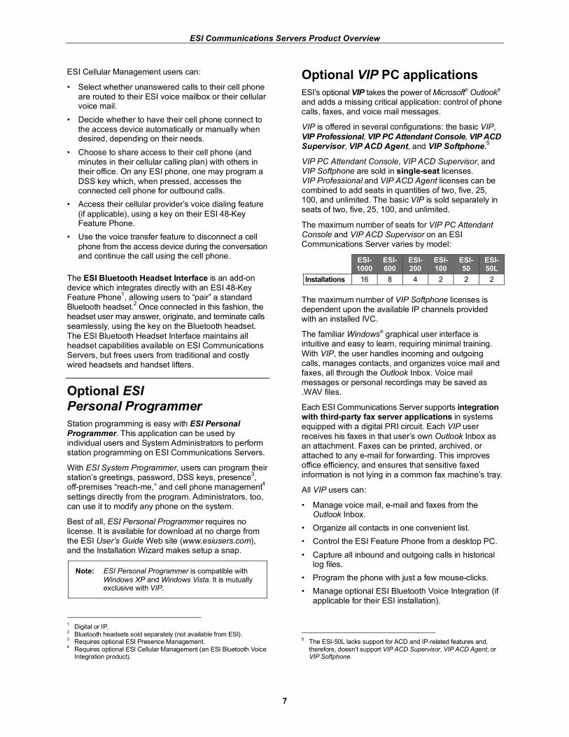
The maximum number of seats for VIP PC Attendant Console and VIP ACD Supervisor on an ESI Communications Server varies by model:
ESI-1000
ESI-600
ESI-200
ESI-100
ESI- 50
ESI- 50L
Installations 16 8 4 2 2 2
The maximum number of VIP Softphone licenses is dependent upon the available IP channels provided with an installed IVC.
The familiar Windows® graphical user interface is intuitive and easy to learn, requiring minimal training.
With VIP, the user handles incoming and outgoing calls, manages contacts, and organizes voice mail and faxes, all through the Outlook Inbox. Voice mail messages or personal recordings may be saved as .WAV files.
Each ESI Communications Server supports integration with third-party fax server applications in systems equipped with a digital PRI circuit. Each VIP user
receives his faxes in that user’s own Outlook Inbox as an attachment. Faxes can be printed, archived, or attached to any e-mail for forwarding. This improves office efficiency, and ensures that sensitive faxed information is not lying in a common fax machine’s tray.
All VIP users can:
• Manage voice mail, e-mail and faxes from the Outlook Inbox.
• Organize all contacts in one convenient list.
• Control the ESI Feature Phone from a desktop PC.
• Capture all inbound and outgoing calls in historical log files.
• Program the phone with just a few mouse-clicks.
• Manage optional ESI Bluetooth Voice Integration (if applicable for their ESI installation).
5 The ESI-50L lacks support for ACD and IP-related features and,
therefore, doesn’t support VIP ACD Supervisor, VIP ACD Agent, or VIP Softphone.
ESI Communications Servers Product Overview
8
Users of VIP Professional, VIP PC Attendant Console, VIP ACD Supervisor, VIP ACD Agent, and VIP Softphone receive additional benefits:
• An enhanced graphical user interface (GUI) to further increase user efficiency.
• Text-messaging to provide a quick method of communication between users of these applications.
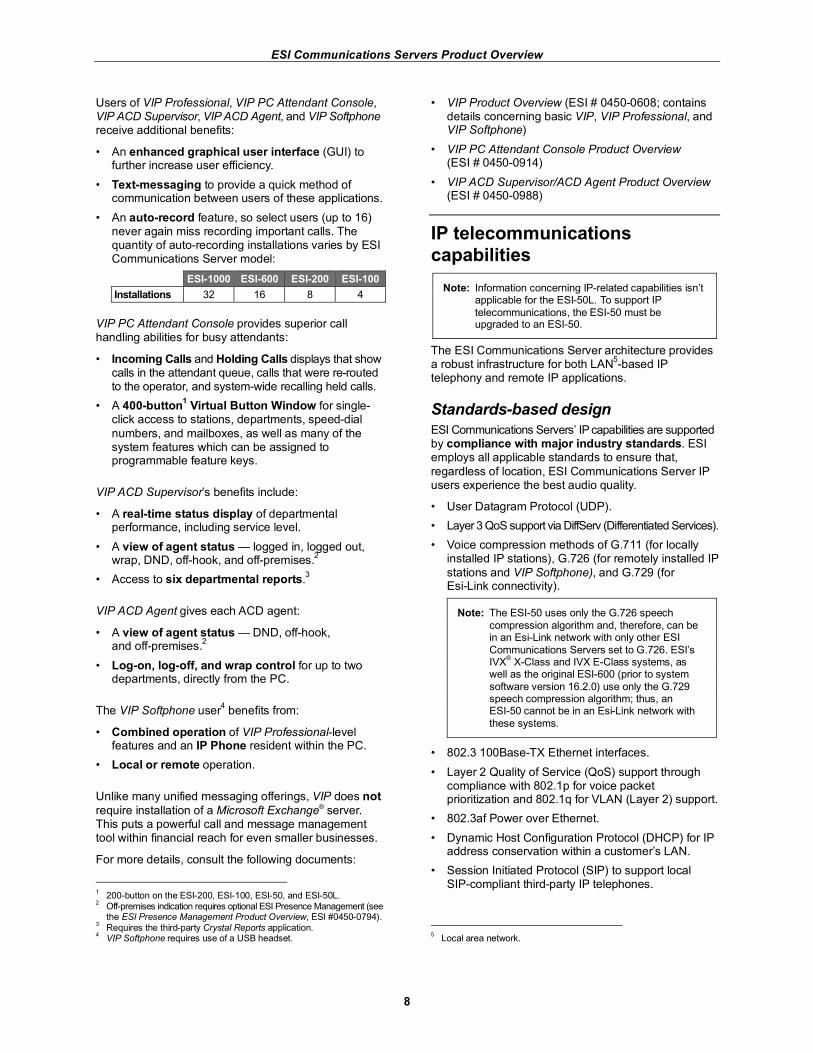
• An auto-record feature, so select users (up to 16) never again miss recording important calls. The quantity of auto-recording installations varies by ESI Communications Server model:
ESI-1000 ESI-600 ESI-200 ESI-100
Installations 32 16 8 4
VIP PC Attendant Console provides superior call handling abilities for busy attendants:
• Incoming Calls and Holding Calls displays that show calls in the attendant queue, calls that were re-routed to the operator, and system-wide recalling held calls.
• A 400-button1 Virtual Button Window for single-
click access to stations, departments, speed-dial
numbers, and mailboxes, as well as many of the system features which can be assigned to programmable feature keys.
VIP ACD Supervisor’s benefits include:
• A real-time status display of departmental performance, including service level.
• A view of agent status — logged in, logged out, wrap, DND, off-hook, and off-premises.
2
• Access to six departmental reports.3
VIP ACD Agent gives each ACD agent:
• A view of agent status — DND, off-hook, and off-premises.
2
• Log-on, log-off, and wrap control for up to two departments, directly from the PC.
The VIP Softphone user4 benefits from:
• Combined operation of VIP Professional-level features and an IP Phone resident within the PC.
• Local or remote operation.
Unlike many unified messaging offerings, VIP does not
require installation of a Microsoft Exchange® server. This puts a powerful call and message management tool within financial reach for even smaller businesses.
For more details, consult the following documents:
1 200-button on the ESI-200, ESI-100, ESI-50, and ESI-50L.
2 Off-premises indication requires optional ESI Presence Management (see
the ESI Presence Management Product Overview, ESI #0450-0794). 3 Requires the third-party Crystal Reports application.
4 VIP Softphone requires use of a USB headset.
• VIP Product Overview (ESI # 0450-0608; contains details concerning basic VIP, VIP Professional, and VIP Softphone)
• VIP PC Attendant Console Product Overview (ESI # 0450-0914)
• VIP ACD Supervisor/ACD Agent Product Overview (ESI # 0450-0988)
IP telecommunications capabilities
Note: Information concerning IP-related capabilities isn’t applicable for the ESI-50L. To support IP
telecommunications, the ESI-50 must be upgraded to an ESI-50.
The ESI Communications Server architecture provides a robust infrastructure for both LAN
5-based IP
telephony and remote IP applications.
Standards-based design
ESI Communications Servers’ IP capabilities are supported by compliance with major industry standards. ESI employs all applicable standards to ensure that,
regardless of location, ESI Communications Server IP users experience the best audio quality.
• User Datagram Protocol (UDP).
• Layer 3 QoS support via DiffServ (Differentiated Services).
• Voice compression methods of G.711 (for locally installed IP stations), G.726 (for remotely installed IP
stations and VIP Softphone), and G.729 (for Esi-Link connectivity).
Note: The ESI-50 uses only the G.726 speech
compression algorithm and, therefore, can be in an Esi-Link network with only other ESI
Communications Servers set to G.726. ESI’s IVX
® X-Class and IVX E-Class systems, as
well as the original ESI-600 (prior to system
software version 16.2.0) use only the G.729 speech compression algorithm; thus, an ESI-50 cannot be in an Esi-Link network with
these systems.
• 802.3 100Base-TX Ethernet interfaces.
• Layer 2 Quality of Service (QoS) support through compliance with 802.1p for voice packet prioritization and 802.1q for VLAN (Layer 2) support.
• 802.3af Power over Ethernet.
• Dynamic Host Configuration Protocol (DHCP) for IP address conservation within a customer’s LAN.
• Session Initiated Protocol (SIP) to support local SIP-compliant third-party IP telephones.
5 Local area network.
ESI Communications Servers Product Overview
9
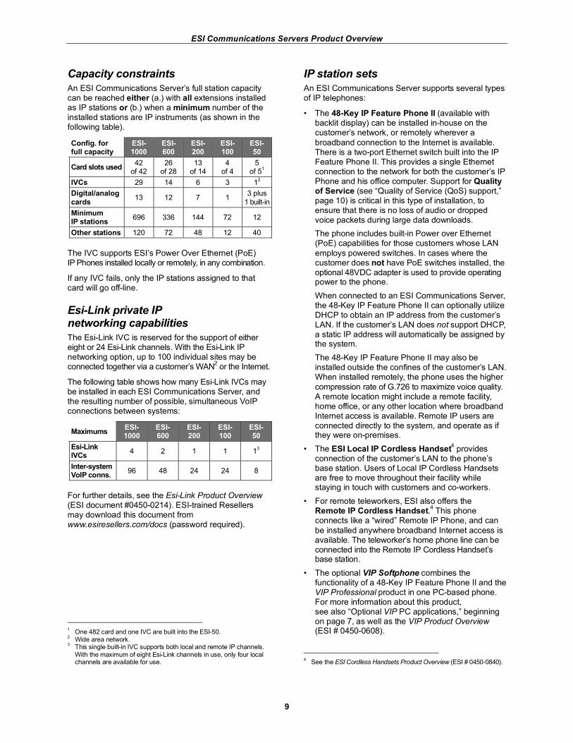
Capacity constraints
An ESI Communications Server’s full station capacity can be reached either (a.) with all extensions installed as IP stations or (b.) when a minimum number of the installed stations are IP instruments (as shown in the following table).
Config. for full capacity
ESI-1000
ESI-600
ESI-200
ESI-100
ESI- 50
Card slots used 42
of 42 26
of 28 13
of 14 4
of 4 5
of 51
IVCs 29 14 6 3 12
Digital/analog
cards 13 12 7 1
3 plus
1 built-in
Minimum IP stations
696 336 144 72 12
Other stations 120 72 48 12 40
The IVC supports ESI’s Power Over Ethernet (PoE) IP Phones installed locally or remotely, in any combination.
If any IVC fails, only the IP stations assigned to that card will go off-line.
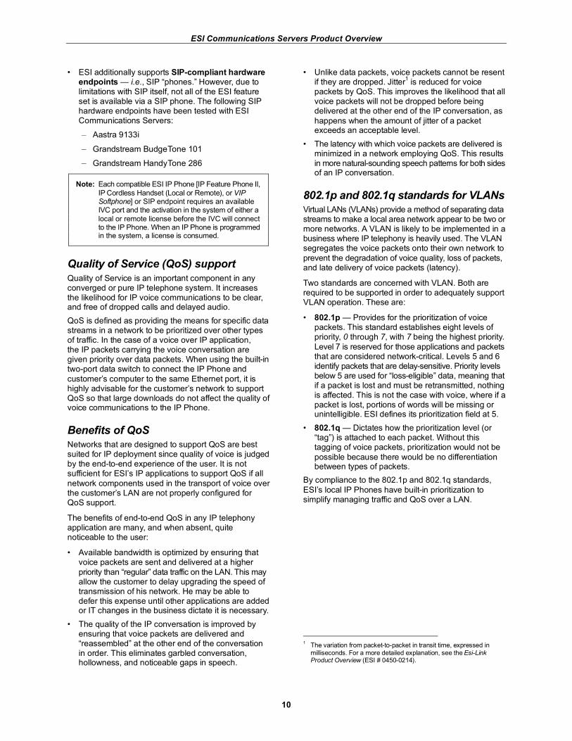
Esi-Link private IP networking capabilities
The Esi-Link IVC is reserved for the support of either eight or 24 Esi-Link channels. With the Esi-Link IP networking option, up to 100 individual sites may be connected together via a customer’s WAN
2 or the Internet.
The following table shows how many Esi-Link IVCs may be installed in each ESI Communications Server, and the resulting number of possible, simultaneous VoIP connections between systems:
Maximums ESI-1000
ESI- 600
ESI- 200
ESI- 100
ESI- 50
Esi-Link IVCs
4 2 1 1 13
Inter-system VoIP conns.
96 48 24 24 8
For further details, see the Esi-Link Product Overview (ESI document #0450-0214). ESI-trained Resellers may download this document from www.esiresellers.com/docs (password required).
1 One 482 card and one IVC are built into the ESI-50.
2 Wide area network.
3 This single built-in IVC supports both local and remote IP channels.
With the maximum of eight Esi-Link channels in use, only four local channels are available for use.
IP station sets
An ESI Communications Server supports several types of IP telephones:
• The 48-Key IP Feature Phone II (available with backlit display) can be installed in-house on the customer’s network, or remotely wherever a
broadband connection to the Internet is available. There is a two-port Ethernet switch built into the IP Feature Phone II. This provides a single Ethernet connection to the network for both the customer’s IP Phone and his office computer. Support for Quality of Service (see “Quality of Service (QoS) support,” page 10) is critical in this type of installation, to ensure that there is no loss of audio or dropped voice packets during large data downloads.
The phone includes built-in Power over Ethernet (PoE) capabilities for those customers whose LAN
employs powered switches. In cases where the customer does not have PoE switches installed, the optional 48VDC adapter is used to provide operating power to the phone.
When connected to an ESI Communications Server, the 48-Key IP Feature Phone II can optionally utilize DHCP to obtain an IP address from the customer’s LAN. If the customer’s LAN does not support DHCP, a static IP address will automatically be assigned by the system.
The 48-Key IP Feature Phone II may also be installed outside the confines of the customer’s LAN. When installed remotely, the phone uses the higher
compression rate of G.726 to maximize voice quality. A remote location might include a remote facility, home office, or any other location where broadband Internet access is available. Remote IP users are connected directly to the system, and operate as if they were on-premises.
• The ESI Local IP Cordless Handset4 provides
connection of the customer’s LAN to the phone’s base station. Users of Local IP Cordless Handsets are free to move throughout their facility while staying in touch with customers and co-workers.
• For remote teleworkers, ESI also offers the Remote IP Cordless Handset.
4 This phone
connects like a “wired” Remote IP Phone, and can
be installed anywhere broadband Internet access is available. The teleworker’s home phone line can be connected into the Remote IP Cordless Handset’s base station.
• The optional VIP Softphone combines the functionality of a 48-Key IP Feature Phone II and the VIP Professional product in one PC-based phone. For more information about this product, see also “Optional VIP PC applications,” beginning on page 7, as well as the VIP Product Overview (ESI # 0450-0608).
4 See the ESI Cordless Handsets Product Overview (ESI # 0450-0840).
ESI Communications Servers Product Overview
10
• ESI additionally supports SIP-compliant hardware endpoints — i.e., SIP “phones.” However, due to limitations with SIP itself, not all of the ESI feature set is available via a SIP phone. The following SIP hardware endpoints have been tested with ESI Communications Servers:
– Aastra 9133i
– Grandstream BudgeTone 101
– Grandstream HandyTone 286
Note: Each compatible ESI IP Phone [IP Feature Phone II,
IP Cordless Handset (Local or Remote), or VIP Softphone] or SIP endpoint requires an available IVC port and the activation in the system of either a
local or remote license before the IVC will connect to the IP Phone. When an IP Phone is programmed in the system, a license is consumed.
Quality of Service (QoS) support
Quality of Service is an important component in any converged or pure IP telephone system. It increases the likelihood for IP voice communications to be clear, and free of dropped calls and delayed audio.
QoS is defined as providing the means for specific data streams in a network to be prioritized over other types of traffic. In the case of a voice over IP application, the IP packets carrying the voice conversation are given priority over data packets. When using the built-in two-port data switch to connect the IP Phone and
customer’s computer to the same Ethernet port, it is highly advisable for the customer’s network to support QoS so that large downloads do not affect the quality of voice communications to the IP Phone.
Benefits of QoS
Networks that are designed to support QoS are best suited for IP deployment since quality of voice is judged by the end-to-end experience of the user. It is not sufficient for ESI’s IP applications to support QoS if all
network components used in the transport of voice over the customer’s LAN are not properly configured for QoS support.
The benefits of end-to-end QoS in any IP telephony application are many, and when absent, quite noticeable to the user:
• Available bandwidth is optimized by ensuring that voice packets are sent and delivered at a higher
priority than “regular” data traffic on the LAN. This may allow the customer to delay upgrading the speed of transmission of his network. He may be able to defer this expense until other applications are added or IT changes in the business dictate it is necessary.
• The quality of the IP conversation is improved by ensuring that voice packets are delivered and “reassembled” at the other end of the conversation in order. This eliminates garbled conversation, hollowness, and noticeable gaps in speech.
• Unlike data packets, voice packets cannot be resent if they are dropped. Jitter
1 is reduced for voice
packets by QoS. This improves the likelihood that all voice packets will not be dropped before being delivered at the other end of the IP conversation, as
happens when the amount of jitter of a packet exceeds an acceptable level.
• The latency with which voice packets are delivered is minimized in a network employing QoS. This results in more natural-sounding speech patterns for both sides of an IP conversation.
802.1p and 802.1q standards for VLANs
Virtual LANs (VLANs) provide a method of separating data streams to make a local area network appear to be two or more networks. A VLAN is likely to be implemented in a business where IP telephony is heavily used. The VLAN segregates the voice packets onto their own network to
prevent the degradation of voice quality, loss of packets, and late delivery of voice packets (latency).
Two standards are concerned with VLAN. Both are required to be supported in order to adequately support VLAN operation. These are:
• 802.1p — Provides for the prioritization of voice packets. This standard establishes eight levels of priority, 0 through 7, with 7 being the highest priority.
Level 7 is reserved for those applications and packets that are considered network-critical. Levels 5 and 6 identify packets that are delay-sensitive. Priority levels below 5 are used for “loss-eligible” data, meaning that if a packet is lost and must be retransmitted, nothing is affected. This is not the case with voice, where if a packet is lost, portions of words will be missing or unintelligible. ESI defines its prioritization field at 5.
• 802.1q — Dictates how the prioritization level (or “tag”) is attached to each packet. Without this tagging of voice packets, prioritization would not be
possible because there would be no differentiation between types of packets.
By compliance to the 802.1p and 802.1q standards,
ESI’s local IP Phones have built-in prioritization to simplify managing traffic and QoS over a LAN.
1 The variation from packet-to-packet in transit time, expressed in
milliseconds. For a more detailed explanation, see the Esi-Link Product Overview (ESI # 0450-0214).
ESI Communications Servers Product Overview
11
Differentiated Services (DiffServ)
This standard is primarily used with remote IP Phones and Esi-Link installations in a WAN environment. This protocol allows IP voice packets to be prioritized over data transmission in LAN/WAN environments whose routers provide prioritization. As with all QoS provisioning
within a LAN or WAN, the network components, such as routers and switches, must be able to support, and be configured for Quality of Service.
Some Internet connections may not support DiffServ. Contact the customer’s ISP to determine whether it supports DiffServ.
Dedicated voice over IP resources
A codec is used to take the analog spoken voice, encode it as an IP packet so it can be compressed and transmitted
as a “data” packet. When received by another IP device (IP Phone or other Esi-Link system), the IP packet is decoded so that it is converted back into analog voice. Communication via IP is not possible without codecs.
Three types of industry-standard codecs are used by ESI’s 48-Key IP Feature Phone II and IVCs: G.711, G.726, and G.729. This refers to the amount of compression that a voice packet will undergo when
being converted into an IP packet.
G.711 is the non-compressed standard from which all other compression standards are established. IP Phones that are locally installed use G.711.
1 Each 48-Key
IP Feature Phone II has built-in G.711 and G.726 codecs. Additionally, each channel of the IVC has dedicated G.711 and G.726 codecs for conversion between unlike compression standards. This conversion ability
of the IVC allows intelligible audio between remotely-installed and locally-installed IP Phones.
Calls to or from a remotely-installed IP Phone use standard compression rates of G.726 (calls to/from the IVC) and G.729 (calls to/from Esi-Link channels). This reduces latency in the IP conversation and minimizes dropped or lost packets. Each of the 24 channels on the IVC has a dedicated G.726 codec to support the connection of remotely installed IP Phones. The Esi-Link IVC is
equipped with 24 dedicated G.729 codecs. By dedicating codecs on each available IVC and Esi-Link IVC channel, an IP Phone or Esi-Link user will never be denied the ability to place or receive a call due to the lack of a codec.
Notes: The ESI-50 uses only the G.726 speech compression algorithm and, therefore, can be in
an Esi-Link network with only other ESI Communications Servers set to G.726. ESI’s IVX
® X-Class and IVX E-Class systems, as well
as the original ESI-600 (prior to system software version 16.2.0) use only the G.729 speech compression algorithm; thus, an ESI-50 cannot be in an Esi-Link network with these systems.
1 Local and remote installations of VIP Softphone use G.726.
Power over Ethernet (PoE)
ESI’s 48-Key IP Feature Phone II complies with the IEEE 802.3af standard for powering devices over a customer’s existing local area network. This enhancement requires the customer to install the appropriate PoE network components, such as switches and routers.
The 48-Key IP Feature Phone II can also be powered by using the optional 48VDC adapter. There are many benefits to designing an IP telephony application with Power over Ethernet capabilities:
• By using the local area network to power the IP Phones, a consistent voltage is provided to all phones without the fluctuations that frequently occur in commercial office buildings.
• Since all power is provided from one location, a single UPS system can be used to protect the IP Phones from power surges, brown-outs, and other electrical anomalies.
• Powering the IP Phones via the customer’s LAN
saves the cost and inconvenience of providing a fused power strip at each IP Phone placement.
ESI has tested several Power over Ethernet devices for
compatibility with its PoE IP Phones:
• Cisco Catalyst 3560 24-port 10/100T PoE
• Adtran Netvanta 1224 PoE
• 3Com Superstack 3 4400 switch power
• 3Com PW130
In addition, the following mid-span Power over Ethernet devices have been tested:
• 3Com 3CNJPSE24 24-port Midspan Solution
• D-link DWL-P1012 12-port PoE Midspan
ESI Communications Servers Product Overview
12
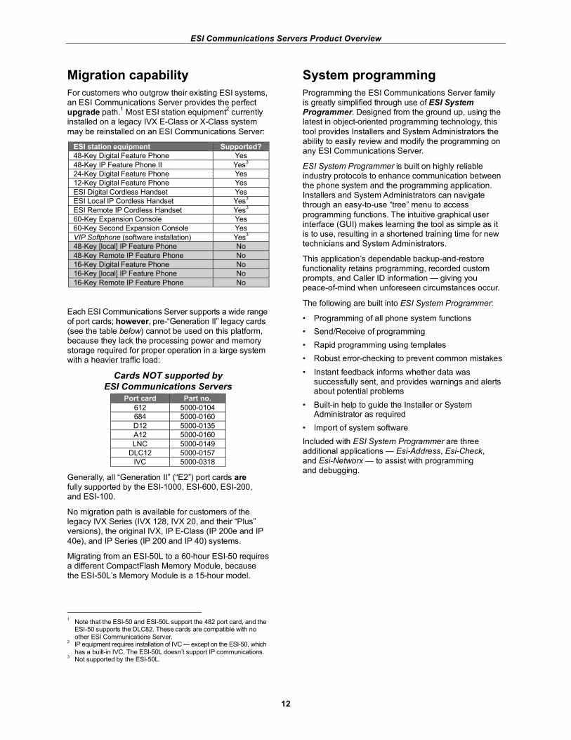
Migration capability
For customers who outgrow their existing ESI systems, an ESI Communications Server provides the perfect upgrade path.
1 Most ESI station equipment
2 currently
installed on a legacy IVX E-Class or X-Class system
may be reinstalled on an ESI Communications Server:
ESI station equipment Supported?
48-Key Digital Feature Phone Yes
48-Key IP Feature Phone II Yes3
24-Key Digital Feature Phone Yes
12-Key Digital Feature Phone Yes
ESI Digital Cordless Handset Yes
ESI Local IP Cordless Handset Yes3
ESI Remote IP Cordless Handset Yes3
60-Key Expansion Console Yes
60-Key Second Expansion Console Yes
VIP Softphone (software installation) Yes3
48-Key [local] IP Feature Phone No
48-Key Remote IP Feature Phone No
16-Key Digital Feature Phone No
16-Key [local] IP Feature Phone No
16-Key Remote IP Feature Phone No
Each ESI Communications Server supports a wide range of port cards; however, pre-“Generation II” legacy cards (see the table below) cannot be used on this platform, because they lack the processing power and memory storage required for proper operation in a large system with a heavier traffic load:
Cards NOT supported by
ESI Communications Servers
Port card Part no.
612 5000-0104
684 5000-0160
D12 5000-0135
A12 5000-0160
LNC 5000-0149
DLC12 5000-0157
IVC 5000-0318
Generally, all “Generation II” (“E2”) port cards are fully supported by the ESI-1000, ESI-600, ESI-200, and ESI-100.
No migration path is available for customers of the legacy IVX Series (IVX 128, IVX 20, and their “Plus” versions), the original IVX, IP E-Class (IP 200e and IP
40e), and IP Series (IP 200 and IP 40) systems.
Migrating from an ESI-50L to a 60-hour ESI-50 requires a different CompactFlash Memory Module, because the ESI-50L’s Memory Module is a 15-hour model.
1 Note that the ESI-50 and ESI-50L support the 482 port card, and the
ESI-50 supports the DLC82. These cards are compatible with no other ESI Communications Server.
2 IP equipment requires installation of IVC — except on the ESI-50, which
has a built-in IVC. The ESI-50L doesn’t support IP communications. 3 Not supported by the ESI-50L.
System programming
Programming the ESI Communications Server family is greatly simplified through use of ESI System Programmer. Designed from the ground up, using the latest in object-oriented programming technology, this
tool provides Installers and System Administrators the ability to easily review and modify the programming on any ESI Communications Server.
ESI System Programmer is built on highly reliable industry protocols to enhance communication between the phone system and the programming application. Installers and System Administrators can navigate through an easy-to-use “tree” menu to access
programming functions. The intuitive graphical user interface (GUI) makes learning the tool as simple as it is to use, resulting in a shortened training time for new technicians and System Administrators.
This application’s dependable backup-and-restore functionality retains programming, recorded custom prompts, and Caller ID information — giving you peace-of-mind when unforeseen circumstances occur.
The following are built into ESI System Programmer:
• Programming of all phone system functions
• Send/Receive of programming
• Rapid programming using templates
• Robust error-checking to prevent common mistakes
• Instant feedback informs whether data was successfully sent, and provides warnings and alerts about potential problems
• Built-in help to guide the Installer or System Administrator as required
• Import of system software
Included with ESI System Programmer are three additional applications — Esi-Address, Esi-Check, and Esi-Networx — to assist with programming and debugging.
ESI Communications Servers Product Overview
13
Specifications and requirements
Capacities
Note: Refer also to “Capacities” in the “Advantage Summary” (page 2).
Because they accept both digital and IP stations, and due to the more flexible configurations this capability allows, ESI Communications Servers possess station capacities far beyond those of most legacy ESI platforms. At the top of the list is the ESI-1000, which supports up
to 816 stations when configured appropriately.1
Each IVC supports 24 channels, to which local IP Phones or remotely installed IP Phones may be connected. This is double the station capacity of any port card that supports digital phones. Therefore, the maximum station capacity can be achieved with maximum use of IVCs and IP stations.
1
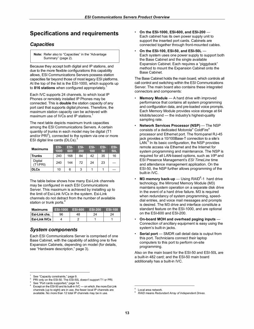
The next table depicts maximum trunk capacities among the ESI Communications Servers. A certain
quantity of trunks in each model may be digital (T1 and/or PRI
2), connected to the system via one or more
ESI digital line cards (DLCs).3
Maximums ESI-1000
ESI-600
ESI-200
ESI-100
ESI- 50
ESI- 50L
Trunks 240 168 84 42 35 16
Digital (T1/PRI)
240 144 72 24 23 —
DLCs 10 6 3 1 1 —
The table below shows how many Esi-Link channels may be configured in each ESI Communications Server. This maximum is achieved by installing up to the limit of Esi-Link IVCs in the system. Esi-Link channels do not detract from the number of available station or trunk ports.
4
Maximums ESI-1000 ESI-600 ESI-200 ESI-100
Esi-Link chs. 96 48 24 24
Esi-Link IVCs 4 2 1 1
System components
Each ESI Communications Server is comprised of one Base Cabinet, with the capability of adding one to five Expansion Cabinets, depending on model (for details, see “Hardware description,” page 3).
1 See “Capacity constraints,” page 9.
2 PRI only on the ESI-50. The ESI-50L doesn’t support T1 or PRI.
3 See “Port cards supported,” page 14.
4 Except on the ESI-50 and its built-in IVC — on which, the more Esi-Link
channels (up to eight) are in use, the fewer local IP channels are available. No more than 12 total IP channels may be in use.
• On the ESI-1000, ESI-600, and ESI-200 — Each cabinet has its own power supply unit to support the inserted port cards. Cabinets are connected together through front-mounted cables.
• On the ESI-100, ESI-50, and ESI-50L — Each system uses one power supply to support both the Base Cabinet and the single available
Expansion Cabinet. Each requires a “piggyback” method to mount the Expansion Cabinet onto the Base Cabinet.
The Base Cabinet holds the main board, which controls all call control and switching within the ESI Communications Server. The main board also contains these integrated connectors and components:
• Memory Module — A hard drive with improved performance that contains all system programming and configuration data, and pre-loaded voice prompts. Each Memory Module provides voice storage at 64
kilobits/second — the industry's highest-quality sampling rate.
• Network Services Processor (NSP) — The NSP
consists of a dedicated Motorola® ColdFire® processor and Ethernet port. The front-panel RJ-45 jack provides a 10/100Base-T connection to a site’s LAN.
5 In its basic configuration, the NSP provides
remote access via Ethernet and the Internet for system programming and maintenance. The NSP is required for all LAN-based options, such as VIP and ESI Presence Management’s ESI TimeLine time
and attendance management application. On the ESI-50, the NSP further allows programming of the built-in IVC.
• M3 memory back-up — Using RAID6-1 hard drive
technology, the Mirrored Memory Module (M3) maintains system operation on a separate disk drive in the event of a hard drive failure. M3 is required when redundancy of system programming, speed-dial entries, and voice mail messages and prompts is desired. The M3 drive and interface constitute a standard feature on the ESI-1000, and are optional on the ESI-600 and ESI-200.
• On-board MOH and overhead paging inputs — Connection of ancillary equipment is easy using the system’s built-in jacks.
• Serial port — SMDR call detail data is output from this port. Technicians connect their laptop
computers to this port to perform on-site programming.
Also on the main board for the ESI-50 and ESI-50L are
a built-in 482 card; and the ESI-50 main board additionally has a built-in IVC.
5 Local area network.
6 RAID means Redundant Array of Independent Drives.
ESI Communications Servers Product Overview
14
Port cards supported
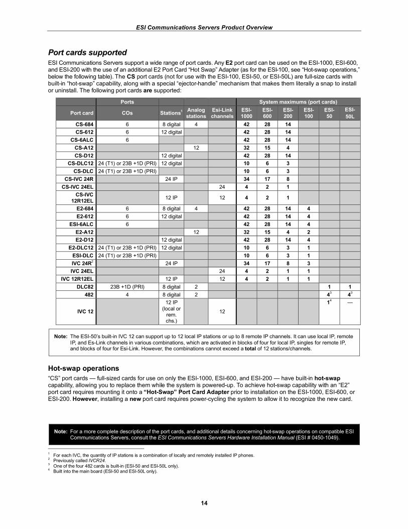
ESI Communications Servers support a wide range of port cards. Any E2 port card can be used on the ESI-1000, ESI-600, and ESI-200 with the use of an additional E2 Port Card “Hot Swap” Adapter (as for the ESI-100, see “Hot-swap operations,” below the following table). The CS port cards (not for use with the ESI-100, ESI-50, or ESI-50L) are full-size cards with built-in “hot-swap” capability, along with a special “ejector-handle” mechanism that makes them literally a snap to install or uninstall. The following port cards are supported:
Ports System maximums (port cards)
Port card COs Stations1
Analog
stations
Esi-Link
channels
ESI-
1000
ESI-
600
ESI-
200
ESI-
100
ESI-
50
ESI-
50L
CS-684 6 8 digital 4 42 28 14
CS-612 6 12 digital 42 28 14
CS-6ALC 6 42 28 14
CS-A12 12 32 15 4
CS-D12 12 digital 42 28 14
CS-DLC12 24 (T1) or 23B +1D (PRI) 12 digital 10 6 3
CS-DLC 24 (T1) or 23B +1D (PRI) 10 6 3
CS-IVC 24R 24 IP 34 17 8
CS-IVC 24EL 24 4 2 1
CS-IVC
12R12EL 12 IP 12 4 2 1
E2-684 6 8 digital 4 42 28 14 4
E2-612 6 12 digital 42 28 14 4
ESI-6ALC 6 42 28 14 4
E2-A12 12 32 15 4 2
E2-D12 12 digital 42 28 14 4
E2-DLC12 24 (T1) or 23B +1D (PRI) 12 digital 10 6 3 1
ESI-DLC 24 (T1) or 23B +1D (PRI) 10 6 3 1
IVC 24R2 24 IP 34 17 8 3
IVC 24EL 24 4 2 1 1
IVC 12R12EL 12 IP 12 4 2 1 1
DLC82 23B +1D (PRI) 8 digital 2 1 1
482 4 8 digital 2 43 4
3
IVC 12
12 IP
(local or rem. chs.)
12
14 —
Note: The ESI-50’s built-in IVC 12 can support up to 12 local IP stations or up to 8 remote IP channels. It can use local IP, remote
IP, and Es-Link channels in various combinations, which are activated in blocks of four for local IP, singles for remote IP, and blocks of four for Esi-Link. However, the combinations cannot exceed a total of 12 stations/channels.
Hot-swap operations
“CS” port cards — full-sized cards for use on only the ESI-1000, ESI-600, and ESI-200 — have built-in hot-swap capability, allowing you to replace them while the system is powered-up. To achieve hot-swap capability with an “E2” port card requires mounting it onto a “Hot-Swap” Port Card Adapter prior to installation on the ESI-1000, ESI-600, or ESI-200. However, installing a new port card requires power-cycling the system to allow it to recognize the new card.
Note: For a more complete description of the port cards, and additional details concerning hot-swap operations on compatible ESI Communications Servers, consult the ESI Communications Servers Hardware Installation Manual (ESI # 0450-1049).
1 For each IVC, the quantity of IP stations is a combination of locally and remotely installed IP phones.
2 Previously called IVCR24.
3 One of the four 482 cards is built-in (ESI-50 and ESI-50L only).
4 Built into the main board (ESI-50 and ESI-50L only).
ESI Communications Servers Product Overview
15
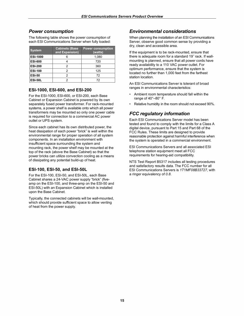
Power consumption
The following table shows the power consumption of each ESI Communications Server when fully loaded:
System Cabinets (Base
and Expansion)
Power consumption
(watts)
ESI-1000 6 1,080
ESI-600 4 720
ESI-200 2 360
ESI-100 2 125
ESI-50 2 72
ESI-50L 2 72
ESI-1000, ESI-600, and ESI-200
For the ESI-1000, ESI-600, or ESI-200, each Base Cabinet or Expansion Cabinet is powered by its own separately fused power transformer. For rack-mounted systems, a power shelf is available onto which all power
transformers may be mounted so only one power cable is required for connection to a commercial AC power outlet or UPS system.
Since each cabinet has its own distributed power, the heat dissipation of each power “brick” is well within the environmental range for proper operation of all system components. In an installation environment with insufficient space surrounding the system and
mounting rack, the power shelf may be mounted at the top of the rack (above the Base Cabinet) so that the power bricks can utilize convection cooling as a means of dissipating any potential build-up of heat.
ESI-100, ESI-50, and ESI-50L
For the ESI-100, ESI-50, and ESI-50L, each Base Cabinet shares a 24-VAC power supply “brick” (five-amp on the ESI-100, and three-amp on the ESI-50 and
ESI-50L) with an Expansion Cabinet which is installed upon the Base Cabinet.
Typically, the connected cabinets will be wall-mounted, which should provide sufficient space to allow venting of heat from the power supply.
Environmental considerations
When planning the installation of an ESI Communications Server, observe good common sense by providing a dry, clean and accessible area.
If the equipment is to be rack-mounted, ensure that there is adequate room for a standard 19˝ rack. If wall-
mounting is planned, ensure that all power cords have ready availability to a 110 VAC power outlet. For optimum performance, ensure that the system is located no further than 1,000 feet from the farthest station location.
An ESI Communications Server is tolerant of broad ranges in environmental characteristics:
• Ambient room temperature should fall within the range of 40°–80° F.
• Relative humidity in the room should not exceed 90%.
FCC regulatory information
Each ESI Communications Server model has been
tested and found to comply with the limits for a Class A digital device, pursuant to Part 15 and Part 68 of the FCC Rules. These limits are designed to provide reasonable protection against harmful interference when the system is operated in a commercial environment.
ESI Communications Servers and all associated ESI telephone station equipment meet all FCC requirements for hearing-aid compatibility.
NTS Test Report B5317 includes all testing procedures and satisfactory results data. The FCC number for all ESI Communications Servers is 1T1MF08B33727, with a ringer equivalency of 0.8.
ESI Communications Servers Product Overview
16
Glossary
Codec — The device required to encode analog spoken voice into IP packets for transmission through a VoIP network. The encoded voice is decoded at the receiving end, converting voice into an analog component.
HDD — Hard Disk Drive; the device on which the system’s operating software program, and voice mail prompts and messages are stored.
IEEE — Institute of Electrical Engineers; the professional organization that establishes standards for, among others, the telecommunications industry.
ICC — Inter-card communication; describes the method by which cards within a cabinet, as well as multiple card cabinets, communicate with each other.
NSP — Network Services Processor; the ESI device, mounted on the Main Board, that provides for an Ethernet connection between the ESI Communications Server and the customer’s local area network (LAN). Multiple applications may run concurrently over the NSP connection: VIP, ESI Presence Management optional ESI TimeLine payroll application, and remote Internet programming.
PoE — Power over Ethernet; this IEEE standard (802.3af) defines the method of injecting power over a customer’s local area network cabling infrastructure to operate TCP/IP devices at the Ethernet port. ESI uses this method, in conjunction with a customer-provided power switch, to operate its PoE local IP Phones.
RF — Radio frequency.
RFID — Radio frequency identification.
RAID1 — Redundant array of independent drives.
VoIP — Voice over Internet Protocol.
About ESI
ESI (Estech Systems, Inc.) is a privately held corporation based in Plano, Texas. Founded in 1987, ESI specializes in business communications systems. ESI pioneered the all-in-one telephone and voice mail system. The original IVX, introduced in 1996, represented a radical breakthrough in system design: the inclusion of a full suite of features within a single integrated system. Since its days as a small start-up, ESI has enjoyed exceptional stability and growth while maintaining its dedication to small-company values — including the need to take care of the most important part of the equation: your business. Copyright © 2008 ESI (Estech Systems, Inc.). IVX is a registered trademark of ESI. Other registered trade names mentioned herein are trademarks of their respective owners. ESI phone systems are protected by various U.S. Patents, granted and pending. Product appearance, and other details and features described herein, are subject to change without notice. Some features may not be available at initial release. More information on ESI and its products is available on the World Wide Web at www.esi-estech.com.