Embed Size (px)
Citation preview
INSTRUCTION MANUAL PROLINK-3
ADVANCED TV & SATLEVEL METER
PROLINK-3
1
1 GENERAL
1.1 Description
The result of uniting PROMAX ELECTRONICA’s long experience in the design ofTV signal analysers with the latest in technological progress, the PROLINK-3 bringstogether the functions installers seek most, all in one small, light-weight, portableinstrument.
Special attention has been given to creating a level meter that has advancedfeatures, but which is also easy to use. Three features in particular are a result of this:a universal keyboard, each function represented by a graphic icon, so that after a briefperiod of introduction to the instrument, access to any function becomes almost intuitive.Secondly, the meter has been entirely designed as an On Screen Display (OSD)instrument so that, when a function is selected, it appears on the monitor listing all thevarious parameters the user has chosen. Finally, there is a rotary selector-button usedfor navigation across the different on-screen menus, to alter parameters and to validatethem at the touch of a button.
The range of frequencies covered, from 45 to 862 MHz and from 920 to 2150 MHz,makes PROLINK-3 an excellent instrument for FM radio, terrestrial TV, cable TV (CATV,'Community Antenna Television', satellite TV, MMDS microwave links, VSAT ('VerySmall Aperture Terminal') systems and digital TV. Furthermore, its high resolutionfrequency, 50 kHz, makes FM measurements much easier.
(1) Trade Mark of the DVB Digital Video Broadcasting Project (1830 to 1832).
October 1999 Page 1
INSTRUCTION MANUAL PROLINK-3
The PROLINK-3 includes the main TV standards: M, N, B, G, I, D, K and L,adopting, apart from the characteristic parameters of the standard, the correctingautomatic system to obtain in all the cases an accurate measuring of the input signallevel. It admits any TV system (PAL, SECAM and NTSC) and allows the user to workdirectly with digital TV signals for which it provides directly the measuring of power andcarrier-to-noise ratio (C/N). Being a multistandard instrument, it can be efficiently usedin any country of the world. Its accuracy and reliability meet the needs of the mostdemanding users.
A powerful microprocessor automatically handles a large part of the operationsnecessary to optimise the process of measurement; for example, continuous frequencysynthesis, measurement correction, the appropriate selection of the attenuators and theautomatic cut-off after the device has been inactive for a certain period of time.
The signal level measured is indicated numerically in absolute values and,optionally, on an analogue bar shown superimposed on the monitor image, thatfacilitates the detection of the maximum level. Moreover, in the LV sound mode, theloudspeaker emits a tone whose frequency depends on the level of the signal received,which is very useful when installing antennas. It is also possible to display on screenthe line synchronism pulse like on an oscilloscope screen.
The Spectrum Analyser mode enables all the signals on a band to be viewed on themonitor at the same time to measure analogue channels level, C/N ratio referenced toa noise frequency defined by the user and digital channels power using an integrationmethod. The bandwidth of the measuring filter can be modified to improve frequencyresolution. This is an indispensable feature, as high channel density is present on alltransmission systems today. Spectrum display can be varied between full span (theentire band) and 8 MHz terrestrial or 32 MHz satellite. In addition, there are two markersin order to locate and list frequencies, to read signal level and frequency difference, andthe level between both.
The selection of sound subcarrier is automatic, depending on the standard, ortunable between 4 and 9 MHz. When decoding TV sound it is possible to choosebetween the NARROW and WIDE filter to obtain the best carrier discrimination. Itincludes a NICAM decoder (with BER measurement); the possibility to commute thechannel that is delivered to the loudspeaker enables the user to check the sound stereoand dual.
To enhance its convenience of use, it has 99 memories to store the differentmeasuring configurations: name of the configuration, frequency, TV system, type ofmeasurement, external units powering, units of measurement and sound. Moreover, theDATALOGGER function permits the acquisition and storage of up to 9801 measures (99configurations x 99 points of measure) that makes it much easier to test systems inwhich a large number of measurements have to be made, and enables furtherprocessing of all the information acquired.
Page 2 October 1999
INSTRUCTION MANUAL PROLINK-3
Also, the level meter permits to supply different voltages to the external unit (13 V/ 15 V / 18 V / 24 V terrestrial TV, and 13 V / 15 V / 18 V / 13 V + 22 kHz / 15 V + 22kHz / 18 V + 22 kHz satellite TV).
A SCART connector has been also included with input/output of audio/video.
The PROLINK-3 is powered by rechargeable batteries or connected to the mainsthrough the supplied external DC power adapter.
It also incorporates a RS-232C interface which enables the user to connect theinstrument to a PC for data recording, remote-control of the instrument and to a printerin order to print out the measurements.
October 1999 Page 3
INSTRUCTION MANUAL PROLINK-3
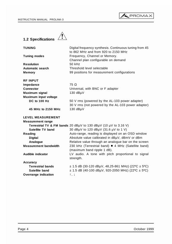
1.2 Specifications
TUNING Digital frequency synthesis. Continuous tuning from 45to 862 MHz and from 920 to 2150 MHz
Tuning modes Frequency, Channel or Memory.Channel plan configurable on demand
Resolution 50 kHzAutomatic search Threshold level selectableMemory 99 positions for measurement configurations
RF INPUTImpedance 75 Ω Connector Universal, with BNC or F adapterMaximum signal 130 dBµVMaximum input voltage
DC to 100 Hz 50 V rms (powered by the AL-103 power adapter)30 V rms (not powered by the AL-103 power adapter)
45 MHz to 2150 MHz 130 dBµV
LEVEL MEASUREMENTMeasurement range
Terrestrial TV & FM bands 20 dBµV to 130 dBµV (10 µV to 3.16 V)Satellite TV band 30 dBµV to 120 dBµV (31.6 µV to 1 V)
Reading Auto-range, reading is displayed on an OSD windowDigital Absolute value calibrated in dBµV, dBmV or dBmAnalogue Relative value through an analogue bar on the screen
Measurement bandwidth 230 kHz (Terrestrial band) 4 MHz (Satellite band)(maximum band ripple 1 dB).
Audible indicator LV audio. A tone with pitch proportional to signalstrength.
AccuracyTerrestrial bands ± 1.5 dB (30-120 dBµV, 48,25-861 MHz) (22ºC ± 5ºC)Satellite band ± 1.5 dB (40-100 dBµV, 920-2050 MHz) (22ºC ± 5ºC)
Overrange indication ↑ , ↓
Page 4 October 1999
INSTRUCTION MANUAL PROLINK-3
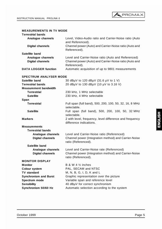
MEASUREMENTS IN TV MODETerrestrial bands
Analogue channels Level, Video-Audio ratio and Carrier-Noise ratio (Autoand Referenced).
Digital channels Channel power (Auto) and Carrier-Noise ratio (Auto andReferenced).
Satellite bandAnalogue channels Level and Carrier-Noise ratio (Auto and Referenced)Digital channels Channel power (Auto) and Carrier-Noise ratio (Auto and
Referenced).DATA LOGGER function Automatic acquisition of up to 9801 measurements
SPECTRUM ANALYSER MODESatellite band 30 dBµV to 120 dBµV (31.6 µV to 1 V)Terrestrial bands 20 dBµV to 130 dBµV (10 µV to 3.16 V)Measurement bandwidth
Terrestrial 230 kHz, 1 MHz selectableSatellite 230 kHz, 4 MHz selectable
SpanTerrestrial Full span (full band), 500, 200, 100, 50, 32, 16, 8 MHz
selectable.Satellite Full span (full band), 500, 200, 100, 50, 32 MHz
selectable.Markers 2 with level, frequency, level difference and frequency
difference indications.Measurements
Terrestrial bandsAnalogue channels Level and Carrier-Noise ratio (Referenced)Digital channels Channel power (Integration method) and Carrier-Noise
ratio (Referenced).Satellite band
Analogue channels Level and Carrier-Noise rate (Referenced)Digital channels Channel power (Integration method) and Carrier-Noise
ratio (Referenced).MONITOR DISPLAYMonitor B & W 4 ½ inchesColour system PAL, SECAM and NTSCTV standard M, N, B, G, I, D, K and LSynchronism and Burst Graphic representation over the pictureSpectrum mode Variable span and reference levelSensibility 40 dBµV for correct synchronismSynchronism 50/60 Hz Automatic selection according to the system
October 1999 Page 5
INSTRUCTION MANUAL PROLINK-3
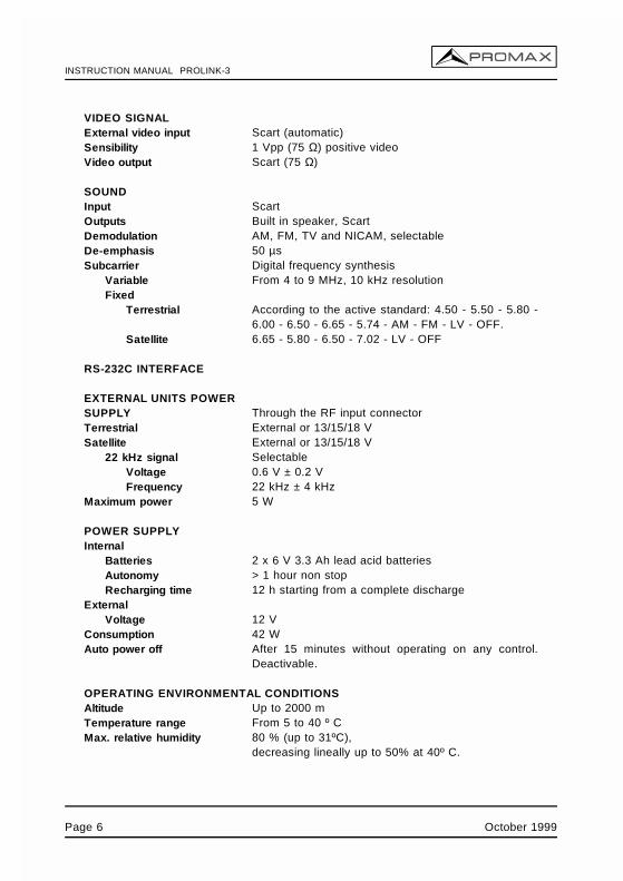
VIDEO SIGNALExternal video input Scart (automatic)Sensibility 1 Vpp (75 Ω) positive videoVideo output Scart (75 Ω)
SOUNDInput ScartOutputs Built in speaker, ScartDemodulation AM, FM, TV and NICAM, selectableDe-emphasis 50 µsSubcarrier Digital frequency synthesis
Variable From 4 to 9 MHz, 10 kHz resolutionFixed
Terrestrial According to the active standard: 4.50 - 5.50 - 5.80 -6.00 - 6.50 - 6.65 - 5.74 - AM - FM - LV - OFF.
Satellite 6.65 - 5.80 - 6.50 - 7.02 - LV - OFF
RS-232C INTERFACE
EXTERNAL UNITS POWER SUPPLY Through the RF input connectorTerrestrial External or 13/15/18 VSatellite External or 13/15/18 V
22 kHz signal SelectableVoltage 0.6 V ± 0.2 VFrequency 22 kHz ± 4 kHz
Maximum power 5 W
POWER SUPPLYInternal
Batteries 2 x 6 V 3.3 Ah lead acid batteriesAutonomy > 1 hour non stopRecharging time 12 h starting from a complete discharge
ExternalVoltage 12 V
Consumption 42 WAuto power off After 15 minutes without operating on any control.
Deactivable.
OPERATING ENVIRONMENTAL CONDITIONSAltitude Up to 2000 mTemperature range From 5 to 40 º CMax. relative humidity 80 % (up to 31ºC),
decreasing lineally up to 50% at 40º C.
Page 6 October 1999
INSTRUCTION MANUAL PROLINK-3
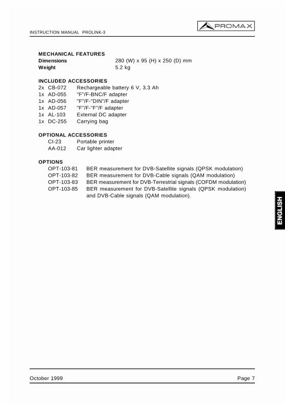
MECHANICAL FEATURESDimensions 280 (W) x 95 (H) x 250 (D) mmWeight 5.2 kg
INCLUDED ACCESSORIES2x CB-072 Rechargeable battery 6 V, 3.3 Ah1x AD-055 "F"/F-BNC/F adapter1x AD-056 "F"/F-"DIN"/F adapter1x AD-057 "F"/F-"F"/F adapter1x AL-103 External DC adapter1x DC-255 Carrying bag
OPTIONAL ACCESSORIESCI-23 Portable printerAA-012 Car lighter adapter
OPTIONSOPT-103-81 BER measurement for DVB-Satellite signals (QPSK modulation)OPT-103-82 BER measurement for DVB-Cable signals (QAM modulation)OPT-103-83 BER measurement for DVB-Terrestrial signals (COFDM modulation)OPT-103-85 BER measurement for DVB-Satellite signals (QPSK modulation)
and DVB-Cable signals (QAM modulation).
October 1999 Page 7

INSTRUCTION MANUAL PROLINK-3
Page 8 October 1999

INSTRUCTION MANUAL PROLINK-3
2 SAFETY RULES
* Use this equipment connected only to systems with their negative of measurementconnected to ground potential.
* The AL-103 external DC adapter is a Class I equipment, for safety reasons plug itto a supply line with the corresponding ground terminal.
* This equipment can be used in Overvoltage Category II installations and PollutionDegree 2 environments.
* When using some of the following accessories use only the specified ones toensure safety.
Rechargeable batteriesExternal DC adapter
* Observe all specified ratings both of supply and measurement.
* Remember that voltages higher than 60 V DC or 30 V AC rms are dangerous.
* Use this instrument under the specified environmental conditions.
* The user is only authorized to carry out the following maintenance operations:
Batteries replacement
On the Maintenance paragraph the proper instructions are given.
Any other change on the equipment should be carried out by qualifiedpersonnel.
* When using the power adaptor, the negative of measurement is at ground potential.
* Do not obstruct the ventilation system of the instrument.
* Use for the signal inputs/outputs, specially when working with high levels,appropriate low radiation cables.
* Follow the cleaning instructions described in the Maintenance paragraph.
October 1999 Page 9
INSTRUCTION MANUAL PROLINK-3
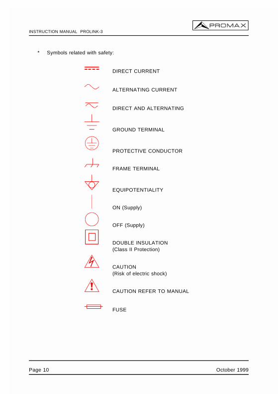
* Symbols related with safety:
DIRECT CURRENT
ALTERNATING CURRENT
DIRECT AND ALTERNATING
GROUND TERMINAL
PROTECTIVE CONDUCTOR
FRAME TERMINAL
EQUIPOTENTIALITY
ON (Supply)
OFF (Supply)
DOUBLE INSULATION(Class II Protection)
CAUTION(Risk of electric shock)
CAUTION REFER TO MANUAL
FUSE
Page 10 October 1999
INSTRUCTION MANUAL PROLINK-3
3 INSTALLATION
3.1 Power Supply
The PROLINK-3 is a portable instrument powered by two 6 V - 3.3 Ah lead acidbatteries. There is also an external DC adapter provided for mains connection andbattery charging.
3.1.1 Operation using the External DC Adapter
Connect the external DC adapter to EXT. SUPPLY [38] on the PROLINK-3 sidepanel. Connect the DC adapter to the mains. Then, press the PROLINK-3 on/off key
[1]. The level meter is now in operation and the batteries are slowly charged.When the instrument is connected to the mains, the CHARGER indicator [7] remainslit.
3.1.2 Operation using Batteries
For the device to operate on the battery, disconnect the power cable and press the
on/off key [1]. The fully charged battery can power the equipment for more than1 hour non-stop.
If batteries are very weak, the battery cut-off circuit will prevent the device fromfunctioning at the same time the beeper will be heard. In such a situation batteries mustbe recharged immediately.
Before taking any measurements, you have to check the charge state of thebatteries by checking the battery charge level indicator BATTERY OK [8] on the frontpanel, or Battery & Lnb function on the TV mode functions menu (see section '4.9.2.3Batteries and External Units Power Supply').
The BATTERY OK [8] led indicates the battery charge state. For battery chargelevels close to 100% and if the unit is powered by the external power adapter, it remainslit. For battery levels between 100% and low battery it starts to flicker, gradually fadingas the charge level decreases. On reaching Low Battery, it ceases to light up at all.When the instrument indicates a Low Battery (the led does not light up) the batteriesmust be charged immediately. When the low battery level is reached, the monitormomentarily displays the message VERY LOW BATTERY and the beeper sounds.
October 1999 Page 11
INSTRUCTION MANUAL PROLINK-3
3.1.2.1 Battery Charging
To fully charge the batteries, connect the instrument to the external DC adapter
without pressing the on/off key [1]. The length of time it takes to recharge itdepends on the condition of the battery. If they are very low the recharging period isabout 12 hours. The CHARGER [7] indicator should remain lit.
IMPORTANT
If batteries are completely discharged, it is advisable to recharge them for a period ofone hour before putting the instrument into operation again. In these circumstances itis not recommended to power external units at the same time batteries are recharged.
IMPORTANT
The lead acid batteries of the instrument must be kept fully charged during periodswhen it is not in use. To ensure the best results, the batteries must always be fullycharged. If the equipment is in storage or is used only occasionally for a long period oftime, it is ABSOLUTELY NECESSARY to check the full-charge functions periodically(every six months, for example), and to compensate for the self-discharging effect of thebatteries. The rate at which a fully charged battery self-discharges depends on thetemperature. For example, at an ambient temperature of 20º C, the battery suffers a50% loss after 16 months, and at 40º C it loses the same charge in only 5 months. Ifthe battery remains very weak for a period of several days, it cannot be recharged sincethe plates are sulphated and must be replaced.
3.2 Installation and Start-up
The PROLINK-3 level meter is designed for use as a portable device.
When the [1] key is pressed, the instrument is in the automatic power-offmode; that is, the device is automatically disconnected fifteen minutes after the last timea key has been pressed. When turning on the unit, automatic power-off mode may be
deactivated by holding down the [1] key until you hear two acoustic indications,later "MANUAL POWER OFF" message will appear on the lower side of the monitor.When the device is operating, it is also possible to select the manual power-off modeby means of the Manual power function of the TV functions menu.
Page 12 October 1999
INSTRUCTION MANUAL PROLINK-3
4 OPERATING INSTRUCTIONS
4.1 Description of the Controls and Elements
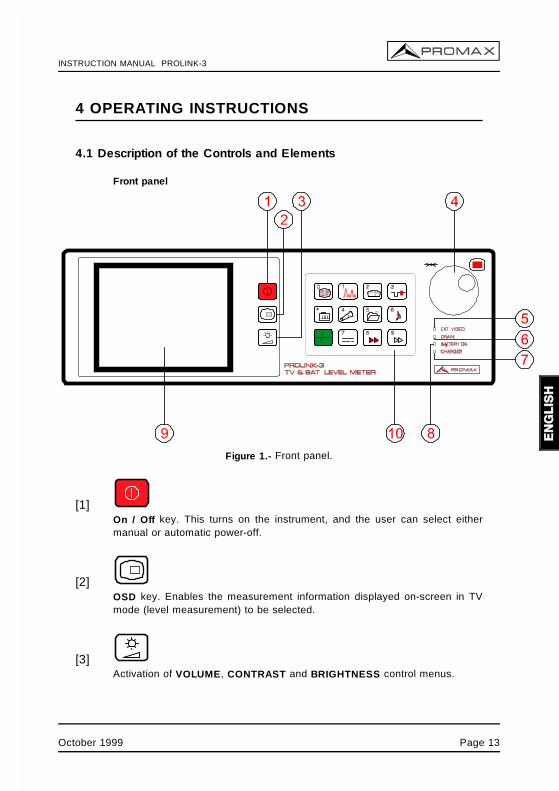
Front panel
Figure 1.- Front panel.
[1]On / Off key. This turns on the instrument, and the user can select eithermanual or automatic power-off.
[2]OSD key. Enables the measurement information displayed on-screen in TVmode (level measurement) to be selected.
[3]Activation of VOLUME, CONTRAST and BRIGHTNESS control menus.
October 1999 Page 13
INSTRUCTION MANUAL PROLINK-3
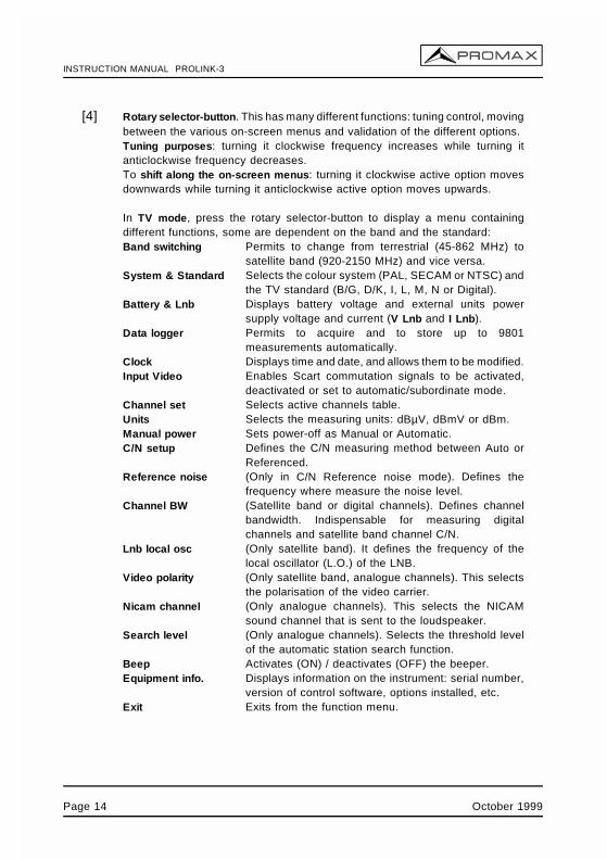
[4] Rotary selector-button. This has many different functions: tuning control, movingbetween the various on-screen menus and validation of the different options. Tuning purposes: turning it clockwise frequency increases while turning itanticlockwise frequency decreases.To shift along the on-screen menus: turning it clockwise active option movesdownwards while turning it anticlockwise active option moves upwards.
In TV mode, press the rotary selector-button to display a menu containingdifferent functions, some are dependent on the band and the standard:Band switching Permits to change from terrestrial (45-862 MHz) to
satellite band (920-2150 MHz) and vice versa.System & Standard Selects the colour system (PAL, SECAM or NTSC) and
the TV standard (B/G, D/K, I, L, M, N or Digital).Battery & Lnb Displays battery voltage and external units power
supply voltage and current (V Lnb and I Lnb).Data logger Permits to acquire and to store up to 9801
measurements automatically.Clock Displays time and date, and allows them to be modified.Input Video Enables Scart commutation signals to be activated,
deactivated or set to automatic/subordinate mode.Channel set Selects active channels table.Units Selects the measuring units: dBµV, dBmV or dBm.Manual power Sets power-off as Manual or Automatic.C/N setup Defines the C/N measuring method between Auto or
Referenced.Reference noise (Only in C/N Reference noise mode). Defines the
frequency where measure the noise level.Channel BW (Satellite band or digital channels). Defines channel
bandwidth. Indispensable for measuring digitalchannels and satellite band channel C/N.
Lnb local osc (Only satellite band). It defines the frequency of thelocal oscillator (L.O.) of the LNB.
Video polarity (Only satellite band, analogue channels). This selectsthe polarisation of the video carrier.
Nicam channel (Only analogue channels). This selects the NICAMsound channel that is sent to the loudspeaker.
Search level (Only analogue channels). Selects the threshold levelof the automatic station search function.
Beep Activates (ON) / deactivates (OFF) the beeper.Equipment info. Displays information on the instrument: serial number,
version of control software, options installed, etc.Exit Exits from the function menu.
Page 14 October 1999
INSTRUCTION MANUAL PROLINK-3
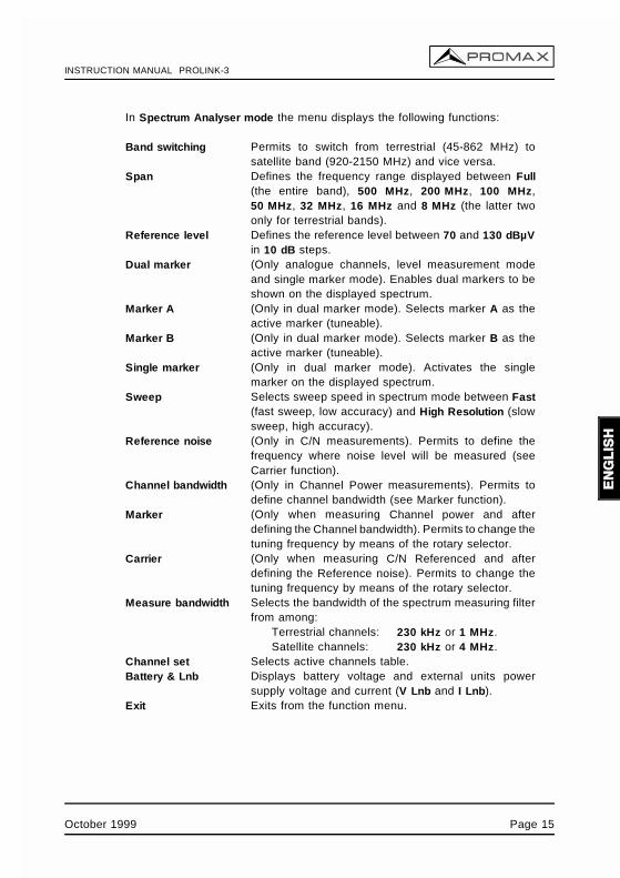
In Spectrum Analyser mode the menu displays the following functions:
Band switching Permits to switch from terrestrial (45-862 MHz) tosatellite band (920-2150 MHz) and vice versa.
Span Defines the frequency range displayed between Full(the entire band), 500 MHz, 200 MHz, 100 MHz,50 MHz, 32 MHz, 16 MHz and 8 MHz (the latter twoonly for terrestrial bands).
Reference level Defines the reference level between 70 and 130 dBµVin 10 dB steps.
Dual marker (Only analogue channels, level measurement modeand single marker mode). Enables dual markers to beshown on the displayed spectrum.
Marker A (Only in dual marker mode). Selects marker A as theactive marker (tuneable).
Marker B (Only in dual marker mode). Selects marker B as theactive marker (tuneable).
Single marker (Only in dual marker mode). Activates the singlemarker on the displayed spectrum.
Sweep Selects sweep speed in spectrum mode between Fast(fast sweep, low accuracy) and High Resolution (slowsweep, high accuracy).
Reference noise (Only in C/N measurements). Permits to define thefrequency where noise level will be measured (seeCarrier function).
Channel bandwidth (Only in Channel Power measurements). Permits todefine channel bandwidth (see Marker function).
Marker (Only when measuring Channel power and afterdefining the Channel bandwidth). Permits to change thetuning frequency by means of the rotary selector.
Carrier (Only when measuring C/N Referenced and afterdefining the Reference noise). Permits to change thetuning frequency by means of the rotary selector.
Measure bandwidth Selects the bandwidth of the spectrum measuring filterfrom among:
Terrestrial channels: 230 kHz or 1 MHz.Satellite channels: 230 kHz or 4 MHz.
Channel set Selects active channels table.Battery & Lnb Displays battery voltage and external units power
supply voltage and current (V Lnb and I Lnb).Exit Exits from the function menu.
October 1999 Page 15
INSTRUCTION MANUAL PROLINK-3
[5] EXT VIDEO. Video signal presence light indicatorIt lights up when an external video signal is present through the SCARTconnector [39].
[6] DRAINExternal units power supply indicator. Lights up when the PROLINK-3 suppliesa current to the external unit.
[7] CHARGERExternal DC adapter operation indicator. When batteries are installed the batterycharger is automatically activated.
[8] BATTERY OKBattery charge level indicator.
[9] MONITOR
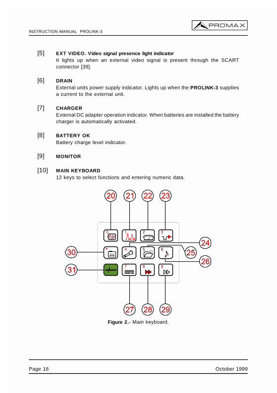
[10] MAIN KEYBOARD12 keys to select functions and entering numeric data.
Figure 2.- Main keyboard.
Page 16 October 1999
INSTRUCTION MANUAL PROLINK-3
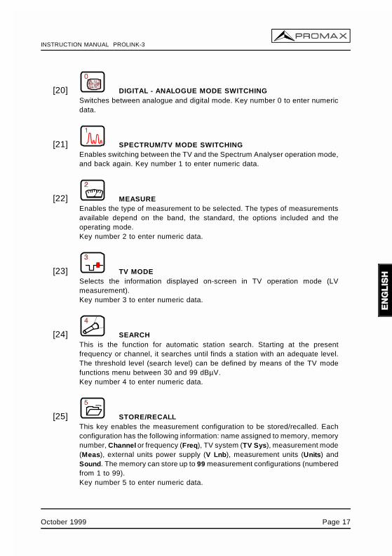
[20] DIGITAL - ANALOGUE MODE SWITCHINGSwitches between analogue and digital mode. Key number 0 to enter numericdata.
[21] SPECTRUM/TV MODE SWITCHINGEnables switching between the TV and the Spectrum Analyser operation mode,and back again. Key number 1 to enter numeric data.
[22] MEASUREEnables the type of measurement to be selected. The types of measurementsavailable depend on the band, the standard, the options included and theoperating mode.Key number 2 to enter numeric data.
[23] TV MODESelects the information displayed on-screen in TV operation mode (LVmeasurement). Key number 3 to enter numeric data.
[24] SEARCHThis is the function for automatic station search. Starting at the presentfrequency or channel, it searches until finds a station with an adequate level.The threshold level (search level) can be defined by means of the TV modefunctions menu between 30 and 99 dBµV.Key number 4 to enter numeric data.
[25] STORE/RECALLThis key enables the measurement configuration to be stored/recalled. Eachconfiguration has the following information: name assigned to memory, memorynumber, Channel or frequency (Freq), TV system (TV Sys), measurement mode(Meas), external units power supply (V Lnb), measurement units (Units) andSound. The memory can store up to 99 measurement configurations (numberedfrom 1 to 99).Key number 5 to enter numeric data.
October 1999 Page 17
INSTRUCTION MANUAL PROLINK-3
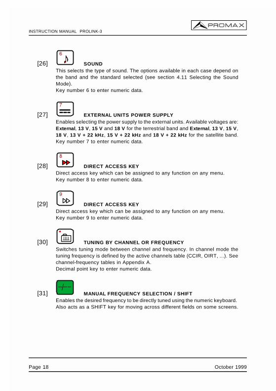
[26] SOUNDThis selects the type of sound. The options available in each case depend onthe band and the standard selected (see section 4.11 Selecting the SoundMode).Key number 6 to enter numeric data.
[27] EXTERNAL UNITS POWER SUPPLYEnables selecting the power supply to the external units. Available voltages are:External, 13 V, 15 V and 18 V for the terrestrial band and External, 13 V, 15 V,18 V, 13 V + 22 kHz, 15 V + 22 kHz and 18 V + 22 kHz for the satellite band.Key number 7 to enter numeric data.
[28] DIRECT ACCESS KEYDirect access key which can be assigned to any function on any menu.Key number 8 to enter numeric data.
[29] DIRECT ACCESS KEYDirect access key which can be assigned to any function on any menu.Key number 9 to enter numeric data.
[30] TUNING BY CHANNEL OR FREQUENCYSwitches tuning mode between channel and frequency. In channel mode thetuning frequency is defined by the active channels table (CCIR, OIRT, ...). Seechannel-frequency tables in Appendix A. Decimal point key to enter numeric data.
[31] MANUAL FREQUENCY SELECTION / SHIFTEnables the desired frequency to be directly tuned using the numeric keyboard. Also acts as a SHIFT key for moving across different fields on some screens.
Page 18 October 1999
INSTRUCTION MANUAL PROLINK-3
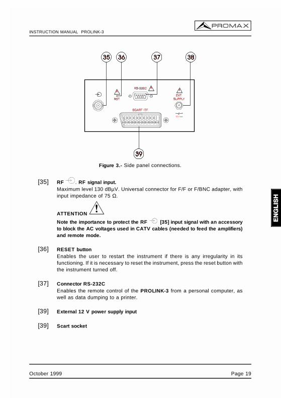
Figure 3.- Side panel connections.
[35] RF . RF signal input.Maximum level 130 dBµV. Universal connector for F/F or F/BNC adapter, withinput impedance of 75 Ω.
ATTENTION
Note the importance to protect the RF [35] input signal with an accessoryto block the AC voltages used in CATV cables (needed to feed the amplifiers)and remote mode.
[36] RESET buttonEnables the user to restart the instrument if there is any irregularity in itsfunctioning. If it is necessary to reset the instrument, press the reset button withthe instrument turned off.
[37] Connector RS-232CEnables the remote control of the PROLINK-3 from a personal computer, aswell as data dumping to a printer.
[39] External 12 V power supply input
[39] Scart socket
October 1999 Page 19
INSTRUCTION MANUAL PROLINK-3
4.2 Adjustment of Volume and Monitor Parameters
Repeatedly pressing key [3] sequentially activates the VOLUME, CONTRAST,and BRIGHTNESS control menus. On activation of a menu for a specific parameter thescreen displays a horizontal bar whose length is proportional to the parameter level, tomodify this value simply turn the rotary selector [4]. To exit the menu and validate thenew value press the rotary selector [4].
4.3 Selecting the Operation Mode: TV / Spectrum Analyser
The PROLINK-3 has two basic operation modes: TV and Spectrum Analyser. To
switch from one operation mode to the other press key [21].
In the TV operation mode the demodulated television signal is shown on-screen; thisis the default operation mode, various functions can be selected, as shown in thefollowing paragraphs.
In the Spectrum Analyser operation mode the screen displays the power spectrumof the active band (terrestrial or satellite). The span, the reference level and themeasuring filter bandwidth are variable as will be shown in paragraph '4.10 SpectrumAnalyser Operation Mode'.
4.4 RF Band Selection: 45-862 MHz / 920-2150 MHz
Tuning is continuous between 45 and 862 MHz (terrestrial band) and between 920and 2150 MHz (satellite band). There are three ways of changing the active band:
1) Press the rotary selector [4] to accede to the functions menu, if necessary turnit to select the Band switching function and then press it again. The RF bandwill be switched automatically.
2) Press key [31] and select a frequency on the new band using the numerickeyboard. The fifth digit and second decimal act as confirmation. For example,if the active band is the 920 to 2150 MHz band and you wish to tune the
49 MHz frequency (belonging to the 45 to 862 MHz band), press key [31]
and then enter 49.00 or 0049.0 using the numeric keyboard.
3) Recall a memory with a tuning frequency belonging to the band you wish toaccess. (See section '4.12 Measurement Configuration Memories').
Page 20 October 1999
INSTRUCTION MANUAL PROLINK-3
4.5 Channel Tuning / Frequency Tuning
Pressing key [30] the PROLINK-3 switches from frequency tuning to channeltuning and back again.
In channel tuning mode turning the rotary selector [4] sequentially tunes thechannels defined in the active channels table (see the Channel set function in the TVmode functions menu, section '4.9.2.7 Selecting the Channels Table'). When turning itclockwise frequency increases while turning it anticlockwise frequency decreases.
In frequency tuning mode there are two ways of tuning:
1. Turning the rotary selector [4].Turning the rotary selector [4] selects the desired frequency (tuning iscontinuous from 45 to 862 MHz and from 920 to 2150 MHz). When turning itclockwise frequency increases while turning it anticlockwise frequencydecreases.
2. Using the keyboard.
Press key [31] (the frequency listing will disappear), next enter thefrequency value in MHz using the numeric keyboard, the fifth digit and thesecond decimal act as confirmation. The PROLINK-3 will calculate the tuneablefrequency closest to the entered value and then display it on-screen.
4.6 Automatic Transmission Search
In the TV mode, by pressing the [24] key search starts at the presentfrequency or channel until it finds a transmission with a level higher than the searchlevel. The threshold level is defined by means of the Search level function of the TVmode functions menu (see paragraph '4.9.2.15 Search Level'.).
The Search function halts the search process when the end of the present band isreached, if it is in frequency mode, or when a key is pressed. In channel mode, thesearch process is halted when the last channel of the group selected is reached (seeAppendix A). The sound is deactivated during the search process.
October 1999 Page 21
INSTRUCTION MANUAL PROLINK-3
4.7 Selecting Analogue / Digital Mode
Measuring the characteristics of a channel depends, in the first place, on the typeof modulation: analogue or digital.
Use key [20] to switch between analogue and digital channels. Whenswitching to a new modulation, the PROLINK-3 activates the last measurementconfiguration used for that modulation.
4.8 External Units Power Supply (EXT. SUPPLY)
The PROLINK-3 can supply the voltage needed to power the external units (antennapreamplifiers, in the case of terrestrial TV, or LNB, in the case of satellite TV).
Maximum input levels
DC to 100 Hz 50 V rms (powered by the AL-103 power adapter)30 V rms (not powered by the AL-103 power adapter)
45 MHz to 2150 MHz 130 dBµV
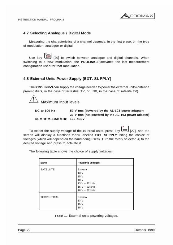
To select the supply voltage of the external units, press key [27], and thescreen will display a functions menu labelled EXT. SUPPLY listing the choice ofvoltages (which will depend on the band being used). Turn the rotary selector [4] to thedesired voltage and press to activate it.
The following table shows the choice of supply voltages:
Band Powering voltages
SATELLITE External13 V15 V18 V 13 V + 22 kHz15 V + 22 kHz18 V + 22 kHz
TERRESTRIAL External13 V15 V18 V
Table 1.- External units powering voltages.
Page 22 October 1999
INSTRUCTION MANUAL PROLINK-3
In the External power supply mode the unit powering the amplifiers before theantenna (terrestrial television) or the satellite TV receiver (house-hold or community)also powers the external units.
The DRAIN [6] indicator lights when current is flowing to the external unit. If anykind of problem occurs (e.g., a short circuit), an error message appears on the monitor('SUPPLY SHORT'), the acoustic indicator will be heard and the instrument will ceaseto supply power. The PROLINK-3 does not return to its normal operating state until theproblem has been solved.
WARNING
When the external unit is powered with one of these voltages, particulary 18 V, it is notadvisable for the instrument to function for more than three minutes non-stop. Since thetotal consumption is very high, the duration of the battery charge is shortenedconsiderably. It is advisable to disconnect the instrument when it is not takingmeasurements.
October 1999 Page 23
INSTRUCTION MANUAL PROLINK-3
4.9 TV Operating Mode
4.9.1 Selecting the Measurement Mode (MEASURE)
The types of measurements available depend on the band, the standard, theoperating mode and the options included in the appliance.
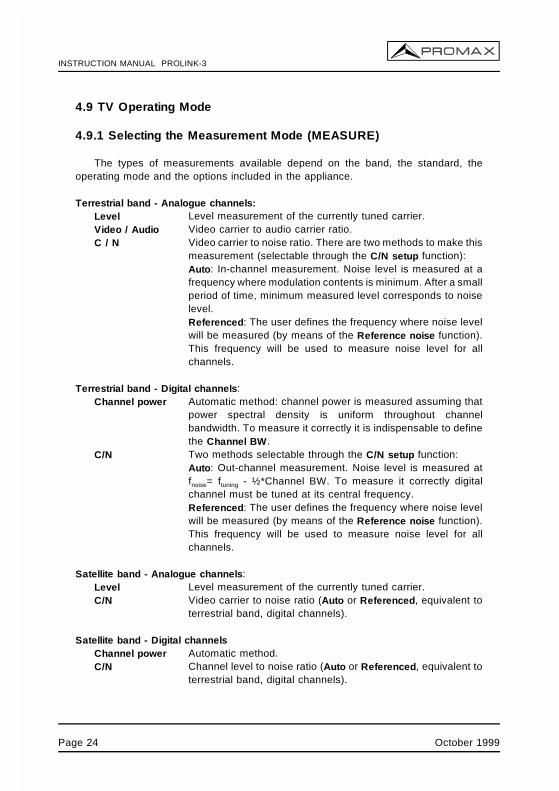
Terrestrial band - Analogue channels:Level Level measurement of the currently tuned carrier.Video / Audio Video carrier to audio carrier ratio.C / N Video carrier to noise ratio. There are two methods to make this
measurement (selectable through the C/N setup function): Auto: In-channel measurement. Noise level is measured at afrequency where modulation contents is minimum. After a smallperiod of time, minimum measured level corresponds to noiselevel.Referenced: The user defines the frequency where noise levelwill be measured (by means of the Reference noise function).This frequency will be used to measure noise level for allchannels.
Terrestrial band - Digital channels:Channel power Automatic method: channel power is measured assuming that
power spectral density is uniform throughout channelbandwidth. To measure it correctly it is indispensable to definethe Channel BW.
C/N Two methods selectable through the C/N setup function:Auto: Out-channel measurement. Noise level is measured atfnoise= ftuning - ½*Channel BW. To measure it correctly digitalchannel must be tuned at its central frequency.Referenced: The user defines the frequency where noise levelwill be measured (by means of the Reference noise function).This frequency will be used to measure noise level for allchannels.
Satellite band - Analogue channels:Level Level measurement of the currently tuned carrier.C/N Video carrier to noise ratio (Auto or Referenced, equivalent to
terrestrial band, digital channels).
Satellite band - Digital channelsChannel power Automatic method.C/N Channel level to noise ratio (Auto or Referenced, equivalent to
terrestrial band, digital channels).
Page 24 October 1999
INSTRUCTION MANUAL PROLINK-3
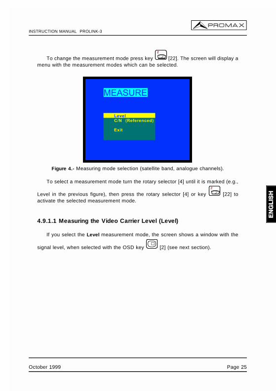
To change the measurement mode press key [22]. The screen will display amenu with the measurement modes which can be selected.
Figure 4.- Measuring mode selection (satellite band, analogue channels).
To select a measurement mode turn the rotary selector [4] until it is marked (e.g.,
Level in the previous figure), then press the rotary selector [4] or key [22] toactivate the selected measurement mode.
4.9.1.1 Measuring the Video Carrier Level (Level)
If you select the Level measurement mode, the screen shows a window with the
signal level, when selected with the OSD key [2] (see next section).
October 1999 Page 25
INSTRUCTION MANUAL PROLINK-3
WARNING
If a sudden signal level increase is produced at the RF input, and it is beyond the totalsignal levels of:
Terrestrial band: 95 dBµVSatellite band: 105 dBµV
the tuning circuit may become out of control, giving as a result wrong level readings.
If this situation occurs, disconnect the input signal, change to Spectrum Analyser modeand select a Reference Level of 130 dBµV. Then connect the signal again and modifythe Reference Level according to present signals.
Similar effects can be observed when at the RF input appears an important number ofcarriers with a high level. To be able to determinate the equivalent level of a carriergroup (with similar levels) at the RF input, it is possible to use the expression:
Lt=L + 10 log N
Lt: equivalent total levelL: average level of the carriers groupN: number of carriers
So, if there are ten carriers with a level around 90 dBµV, their equivalent level will be:
90 dBµV + 10 log 10 = 100 dBµV
Observe that in this case, loss of tuning by overload of the RF input may occur besidesother effects such as tuner saturation and generation of intermodulation products thatmay mask the spectrum visualization.
Page 26 October 1999
INSTRUCTION MANUAL PROLINK-3
4.9.1.1.1 On-screen Measurement Information
In TV operation mode, the measurement information to be displayed on-screen is
selected by pressing key [2]. Three possibilities are offered, selected cyclically:
- TV image with a window in the lower part of the screen displaying the signallevel and frequency/channel.
- TV image with a window displaying information on the name assigned tomemory, power supply to external units, sound, colour system, TV standard,level and frequency/channel.
- TV image only.
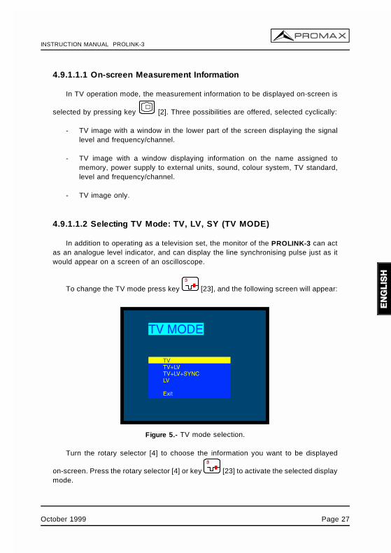
4.9.1.1.2 Selecting TV Mode: TV, LV, SY (TV MODE)
In addition to operating as a television set, the monitor of the PROLINK-3 can actas an analogue level indicator, and can display the line synchronising pulse just as itwould appear on a screen of an oscilloscope.
To change the TV mode press key [23], and the following screen will appear:
Figure 5.- TV mode selection.
Turn the rotary selector [4] to choose the information you want to be displayed
on-screen. Press the rotary selector [4] or key [23] to activate the selected displaymode.
October 1999 Page 27
INSTRUCTION MANUAL PROLINK-3
The operation modes available are:
TV: Monitor operating as a conventional television set.TV+LV: Monitor operating as a conventional television set, with a level
indicator on the upper part of the screen (the analogue bar).TV+LV+SY: Monitor operating as a conventional television set, with a level
indicator and the line synchronizing pulse displayed on thescreen.
LV: Signal level indication on the upper part of the screen(analogue bar).
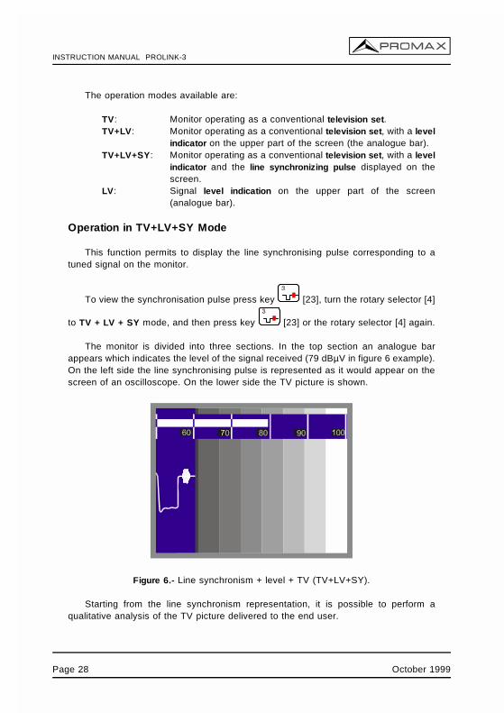
Operation in TV+LV+SY Mode
This function permits to display the line synchronising pulse corresponding to atuned signal on the monitor.
To view the synchronisation pulse press key [23], turn the rotary selector [4]
to TV + LV + SY mode, and then press key [23] or the rotary selector [4] again.
The monitor is divided into three sections. In the top section an analogue barappears which indicates the level of the signal received (79 dBµV in figure 6 example).On the left side the line synchronising pulse is represented as it would appear on thescreen of an oscilloscope. On the lower side the TV picture is shown.
Figure 6.- Line synchronism + level + TV (TV+LV+SY).
Starting from the line synchronism representation, it is possible to perform aqualitative analysis of the TV picture delivered to the end user.
Page 28 October 1999
INSTRUCTION MANUAL PROLINK-3
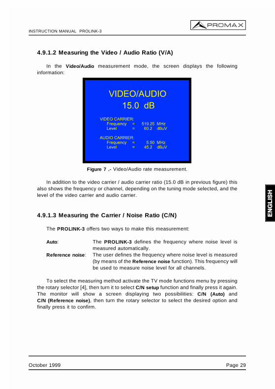
4.9.1.2 Measuring the Video / Audio Ratio (V/A)
In the Video/Audio measurement mode, the screen displays the followinginformation:
Figure 7 .- Video/Audio rate measurement.
In addition to the video carrier / audio carrier ratio (15.0 dB in previous figure) thisalso shows the frequency or channel, depending on the tuning mode selected, and thelevel of the video carrier and audio carrier.
4.9.1.3 Measuring the Carrier / Noise Ratio (C/N)
The PROLINK-3 offers two ways to make this measurement:
Auto: The PROLINK-3 defines the frequency where noise level ismeasured automatically.
Reference noise: The user defines the frequency where noise level is measured(by means of the Reference noise function). This frequency willbe used to measure noise level for all channels.
To select the measuring method activate the TV mode functions menu by pressingthe rotary selector [4], then turn it to select C/N setup function and finally press it again.The monitor will show a screen displaying two possibilities: C/N (Auto) andC/N (Reference noise), then turn the rotary selector to select the desired option andfinally press it to confirm.
October 1999 Page 29
INSTRUCTION MANUAL PROLINK-3
When selecting the C/N (Reference noise) mode it is necessary to define the noisefrequency: access the functions menu and now turn the rotary selector to selectReference noise function and finally press it again. A screen titled REFERENCE NOISE
will be displayed showing the noise frequency in use. To change it press key [31],the current frequency value will disappear and, using the keyboard, you will be able toenter the new reference noise frequency in MHz and with two decimals figures. Thisfrequency also can be modified in the Spectrum operation mode (see 4.10.2.2. C/N(Referenced) Measurement).
The PROLINK-3 carries out C/N ratio measurement in four different ways, accordingto the carrier type and the band in use:
A) Terrestrial band, analogue carrierCarrier level is measured using a quasi-peak detector (230 kHz BW). Noise levelis measured with an average detector and corrected to refer it to channel bandwidth(according to the standard in use).
B) Terrestrial band, digital carrierBoth measurements are done with an average detector (230 kHz) and the samecorrections are introduced on them (bandwidth corrections).
C) Satellite band, analogue carrierCarrier level is measured using a quasi-peak detector (4 MHz BW). Noise level ismeasured with an average detector (4 MHz) and corrected to refer it to channelbandwidth.
D) Satellite band, digital carrierEquivalent to case B but now using the 4 MHz BW filter.
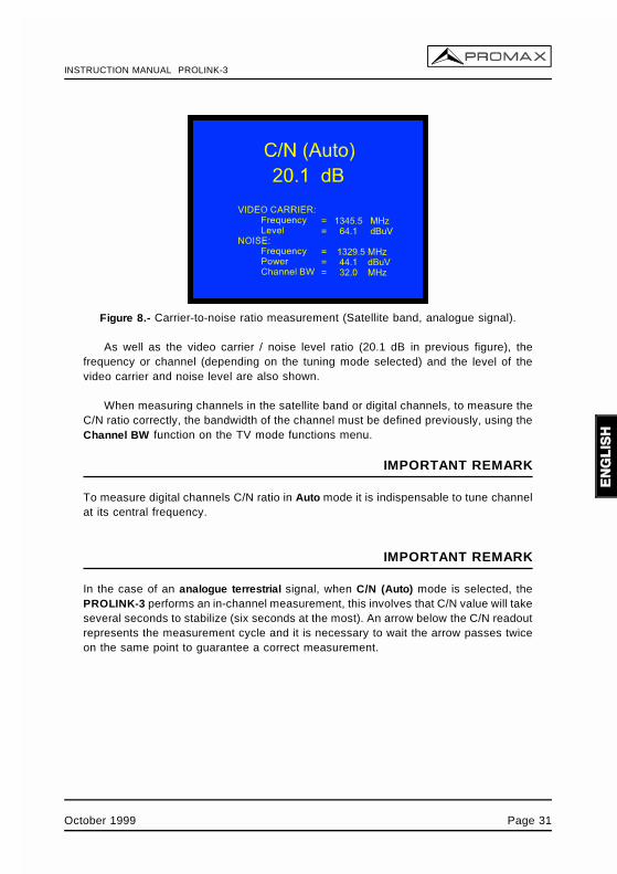
On selecting the Carrier / Noise measurement mode the screen displays thefollowing information:
Page 30 October 1999
INSTRUCTION MANUAL PROLINK-3
Figure 8.- Carrier-to-noise ratio measurement (Satellite band, analogue signal).
As well as the video carrier / noise level ratio (20.1 dB in previous figure), thefrequency or channel (depending on the tuning mode selected) and the level of thevideo carrier and noise level are also shown.
When measuring channels in the satellite band or digital channels, to measure theC/N ratio correctly, the bandwidth of the channel must be defined previously, using theChannel BW function on the TV mode functions menu.
IMPORTANT REMARK
To measure digital channels C/N ratio in Auto mode it is indispensable to tune channelat its central frequency.
IMPORTANT REMARK
In the case of an analogue terrestrial signal, when C/N (Auto) mode is selected, thePROLINK-3 performs an in-channel measurement, this involves that C/N value will takeseveral seconds to stabilize (six seconds at the most). An arrow below the C/N readoutrepresents the measurement cycle and it is necessary to wait the arrow passes twiceon the same point to guarantee a correct measurement.
October 1999 Page 31
INSTRUCTION MANUAL PROLINK-3
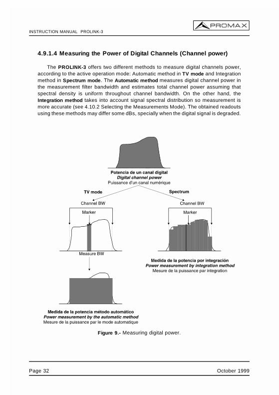
4.9.1.4 Measuring the Power of Digital Channels (Channel power)
The PROLINK-3 offers two different methods to measure digital channels power,according to the active operation mode: Automatic method in TV mode and Integrationmethod in Spectrum mode. The Automatic method measures digital channel power inthe measurement filter bandwidth and estimates total channel power assuming thatspectral density is uniform throughout channel bandwidth. On the other hand, theIntegration method takes into account signal spectral distribution so measurement ismore accurate (see 4.10.2 Selecting the Measurements Mode). The obtained readoutsusing these methods may differ some dBs, specially when the digital signal is degraded.
Figure 9.- Measuring digital power.
Page 32 October 1999
INSTRUCTION MANUAL PROLINK-3
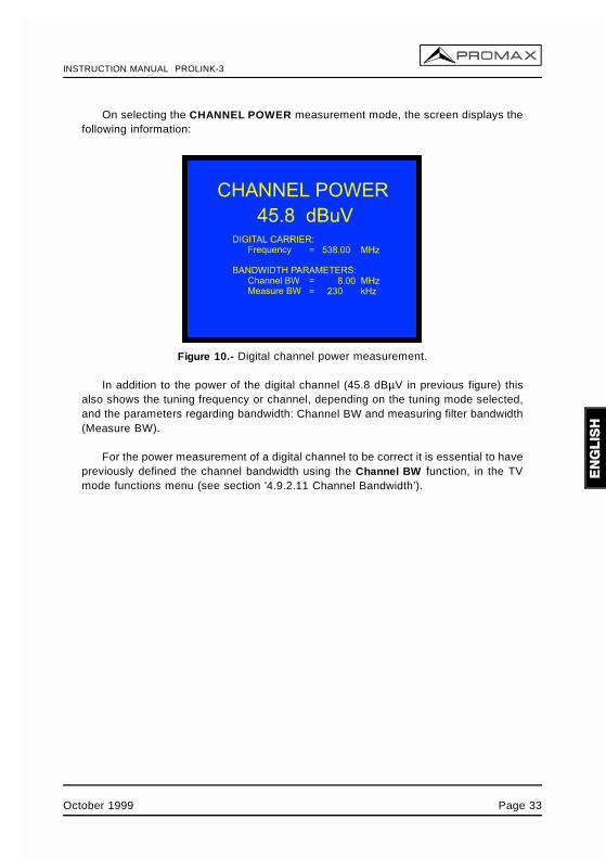
On selecting the CHANNEL POWER measurement mode, the screen displays thefollowing information:
Figure 10.- Digital channel power measurement.
In addition to the power of the digital channel (45.8 dBµV in previous figure) thisalso shows the tuning frequency or channel, depending on the tuning mode selected,and the parameters regarding bandwidth: Channel BW and measuring filter bandwidth(Measure BW).
For the power measurement of a digital channel to be correct it is essential to havepreviously defined the channel bandwidth using the Channel BW function, in the TVmode functions menu (see section '4.9.2.11 Channel Bandwidth’).
October 1999 Page 33
INSTRUCTION MANUAL PROLINK-3
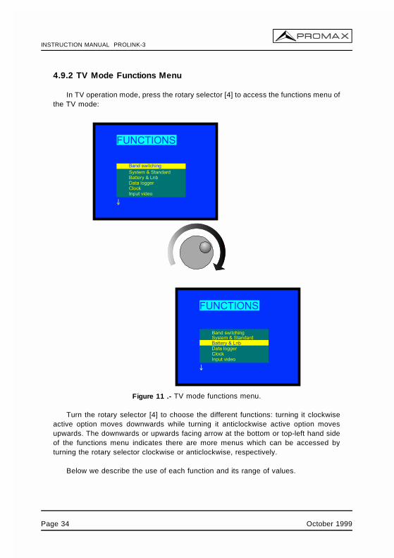
4.9.2 TV Mode Functions Menu
In TV operation mode, press the rotary selector [4] to access the functions menu ofthe TV mode:
Figure 11 .- TV mode functions menu.
Turn the rotary selector [4] to choose the different functions: turning it clockwiseactive option moves downwards while turning it anticlockwise active option movesupwards. The downwards or upwards facing arrow at the bottom or top-left hand sideof the functions menu indicates there are more menus which can be accessed byturning the rotary selector clockwise or anticlockwise, respectively.
Below we describe the use of each function and its range of values.
Page 34 October 1999
INSTRUCTION MANUAL PROLINK-3
4.9.2.1 Selection of the RF Band: (Band switching)
Permits to switch from terrestrial (45-862 MHz) to satellite band (920-2150 MHz) andvice versa.
4.9.2.2 Selection of the TV System and Standard (System & Standard)
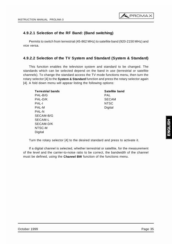
This function enables the television system and standard to be changed. Thestandards which can be selected depend on the band in use (terrestrial or satellitechannels). To change the standard access the TV mode functions menu, then turn therotary selector [4] to the System & Standard function and press the rotary selector again[4]. A fold down menu will appear listing the following options:
Terrestrial bandsPAL-B/GPAL-D/KPAL-IPAL-MPAL-NSECAM-B/GSECAM-LSECAM-D/KNTSC-MDigital
Satellite bandPALSECAMNTSCDigital
Turn the rotary selector [4] to the desired standard and press to activate it.
If a digital channel is selected, whether terrestrial or satellite, for the measurementof the level and the carrier-to-noise ratio to be correct, the bandwidth of the channelmust be defined, using the Channel BW function of the functions menu.
October 1999 Page 35
INSTRUCTION MANUAL PROLINK-3
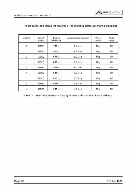
The following table shows the features of the analogue terrestrial channel standards.
System Lines/frame
ChannelBandwidth
Video/sound separation Videomode
Audiomode
B 625/50 7 MHz 5.5 MHz Neg FM
D 625/50 8 MHz 6.5 MHz Neg FM
G 625/50 8 MHz 5.5 MHz Neg FM
H 625/50 8 MHz 5.5 MHz Neg FM
I 625/50 8 MHz 6.0 MHz Neg FM
K 625/50 8 MHz 6.5 MHz Neg FM
L 625/50 8 MHz 6.5 MHz Pos AM
M 525/60 6 MHz 4.5 MHz Neg FM
N 625/50 6 MHz 4.5 MHz Neg FM
Table 2.- Selectable terrestrial analogue standards and their characteristics.
Page 36 October 1999
INSTRUCTION MANUAL PROLINK-3
4.9.2.3 Batteries and External Units Power Supply (Battery & Lnb)
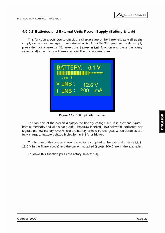
This function allows you to check the charge state of the batteries, as well as thesupply current and voltage of the external units. From the TV operation mode, simplypress the rotary selector [4], select the Battery & Lnb function and press the rotaryselector [4] again. You will see a screen like the following one:
Figure 12.- Battery&Lnb function.
The top part of the screen displays the battery voltage (6,1 V in previous figure),both numerically and with a bar graph. The arrow labelled L Bat below the horizontal barsignals the low battery level where the battery should be charged. When batteries arefully charged, battery voltage indication is 6.1 V or higher.
The bottom of the screen shows the voltage supplied to the external units (V LNB,12.6 V in the figure above) and the current supplied (I LNB, 200.0 mA in the example).
To leave this function press the rotary selector [4].
October 1999 Page 37
INSTRUCTION MANUAL PROLINK-3
4.9.2.4 Data Logger Function
The Data logger function allows the user to carry out, store and/or print out up to9801 measurements in a fully automatic way. It may be understood as a measurementmatrix whose columns address the 99 measuring configurations (defined in the 99memories of the equipment) and whose lines permit to store 99 measurements for everymeasuring configuration (conducted in different points of the system or in the same pointon different times).
Before to proceed to take measurements by means of the Data logger function it isnecessary to store the measuring configuration/s in the memory by using the Storefunction (see paragraph 4.12.1).
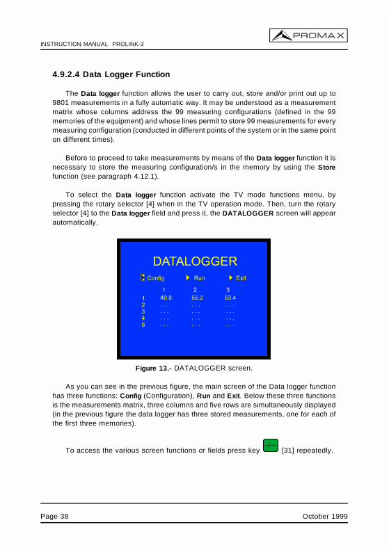
To select the Data logger function activate the TV mode functions menu, bypressing the rotary selector [4] when in the TV operation mode. Then, turn the rotaryselector [4] to the Data logger field and press it, the DATALOGGER screen will appearautomatically.
Figure 13.- DATALOGGER screen.
As you can see in the previous figure, the main screen of the Data logger functionhas three functions: Config (Configuration), Run and Exit. Below these three functionsis the measurements matrix, three columns and five rows are simultaneously displayed(in the previous figure the data logger has three stored measurements, one for each ofthe first three memories).
To access the various screen functions or fields press key [31] repeatedly.
Page 38 October 1999
INSTRUCTION MANUAL PROLINK-3
4.9.2.4.1 Configuring the Data Logger Function
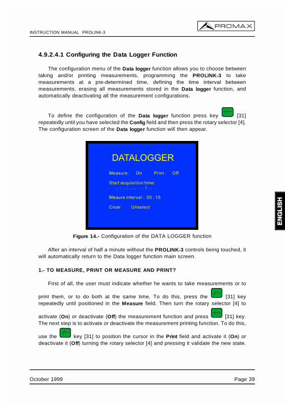
The configuration menu of the Data logger function allows you to choose betweentaking and/or printing measurements, programming the PROLINK-3 to takemeasurements at a pre-determined time, defining the time interval betweenmeasurements, erasing all measurements stored in the Data logger function, andautomatically deactivating all the measurement configurations.
To define the configuration of the Data logger function press key [31]repeatedly until you have selected the Config field and then press the rotary selector [4].The configuration screen of the Data logger function will then appear.
Figure 14.- Configuration of the DATA LOGGER function
After an interval of half a minute without the PROLINK-3 controls being touched, itwill automatically return to the Data logger function main screen.
1.- TO MEASURE, PRINT OR MEASURE AND PRINT?
First of all, the user must indicate whether he wants to take measurements or to
print them, or to do both at the same time. To do this, press the [31] keyrepeatedly until positioned in the Measure field. Then turn the rotary selector [4] to
activate (On) or deactivate (Off) the measurement function and press [31] key.The next step is to activate or deactivate the measurement printing function. To do this,
use the key [31] to position the cursor in the Print field and activate it (On) ordeactivate it (Off) turning the rotary selector [4] and pressing it validate the new state.
October 1999 Page 39
INSTRUCTION MANUAL PROLINK-3
2.- PROGRAMMING THE ALARM
To program the instrument to take measurements and/or print-outs at a specifictime, you must define the time and date the measurements are to be taken (Startacquisition time). If this field is not defined the acquisition of measurements will haveto be activated manually (see section '4.9.2.4.3 Taking Measurements'). Whenprogramming the alarm be sure to have checked that the date and time have beencorrectly defined beforehand (Clock function, paragraph 4.9.2.5) and to have selectedpreviously one measurement to be taken at minimum (see section '4.9.2.4.2 Selectingthe Measurements to be Taken').
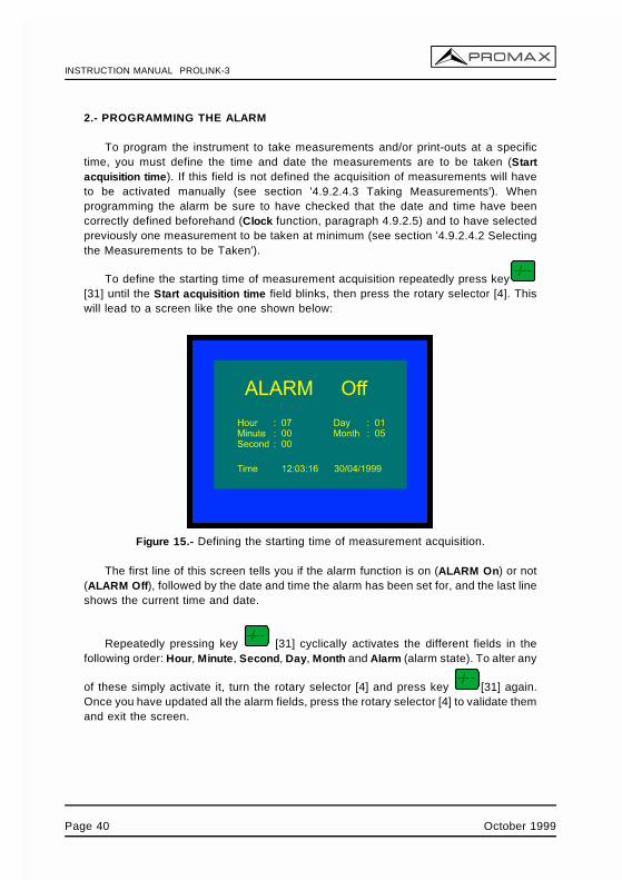
To define the starting time of measurement acquisition repeatedly press key[31] until the Start acquisition time field blinks, then press the rotary selector [4]. Thiswill lead to a screen like the one shown below:
Figure 15.- Defining the starting time of measurement acquisition.
The first line of this screen tells you if the alarm function is on (ALARM On) or not(ALARM Off), followed by the date and time the alarm has been set for, and the last lineshows the current time and date.
Repeatedly pressing key [31] cyclically activates the different fields in thefollowing order: Hour, Minute, Second, Day, Month and Alarm (alarm state). To alter any
of these simply activate it, turn the rotary selector [4] and press key [31] again.Once you have updated all the alarm fields, press the rotary selector [4] to validate themand exit the screen.
Page 40 October 1999
INSTRUCTION MANUAL PROLINK-3
If before activating the alarm (ALARM On) no measurement matrix cell has yet beenactivated (see section '4.9.2.4.2 Selecting the Measurements to be Taken'), the bottomof the screen will show the error message "NOT CELLS SEL." (No cells have beenselected) followed by "DL STOPPED" (Data Logger deactivated).
On reaching the time defined in the Start acquisition time field, the instrument willswitch itself on (if it was switched off) or go to the Data logger mode (if switched on) toautomatically take the measurements and/or produce the print-out.
3.- MULTIPLE MEASUREMENTS: INTERVAL BETWEEN MEASUREMENTS
In the case of having to take multiple measurements at different times the Measureinterval will have to be defined. This field specifies the time interval betweenmeasurements/print-outs. To define it, from the Data logger configuration screen,
repeatedly press key [31] until the section dealing with time in the Measureinterval field has been activated, define the hours by turning the rotary selector [4], then
press key [31] again to go to the minutes field and define these in the same way.
Finally press key [31] again to validate the defined time interval.
You can make as many acquisitions as there are activated rows in themeasurement matrix (if only one row has been activated, then only one measurementwill be taken).
In the case where the Data logger function has been programmed to take more thanone measurement in the time domain, i.e. more than one row has been activated andthe acquisition interval is greater than four minutes, then every time an acquisition ismade the instrument will reprogram the alarm for the next measurement. Then it willswitch itself on three minutes before the time defined in the Measure Interval field inorder to warm up and ensure the highest accuracy.
4.- ERASING MEASUREMENTS STORED IN THE DATA LOGGER AND AUTOMATICDEACTIVATION OF ALL THE CELLS.
The configuration screen also allows you to erase all the measurements stored inthe Data Logger function, as well as automatically deactivating all the activatedmeasurement configurations. To erase the stored measurements select the Clear fieldand press the rotary selector [4]. To deactivate the measurement configurations selectthe Unselect field and press the rotary selector [4].
5.- EXITING THE CONFIGURATION SCREEN
To exit the Data logger function configuration screen press the rotary selector [4].
October 1999 Page 41
INSTRUCTION MANUAL PROLINK-3
4.9.2.4.2 Selecting the Measurements to be Taken
Once the Data logger function has been configured, activate the measurementconfiguration(s) (columns) which you would like to use. The headings of themeasurement matrix columns of the Data logger function coincide with the number ofmemorised measurement configurations, simply place the cursor over each column andyou will see the more important parameters displayed at the bottom of the screen (nameassigned to the memory position, frequency/channel, measurement mode and units ofmeasurement).
To activate the measurement configurations repeatedly press key [31] until thecursor is placed on the columns field, next turn the rotary selector [4] until it ispositioned in the column (memory) that you wish to activate and press the rotaryselector [4].The activated columns are more brilliant than the non activated ones. Todeactivate a column follow the same steps as in activating it.
To activate rows where you wish to store measurements use key [31] to placethe cursor on the rows field, then turn the rotary selector [4] until it is over the row youwant to activate and press the rotary selector [4]. The activated rows are more brilliantthan the non activated ones. To deactivate a row follow the same steps as in activatingit. In the case of activating more than one row, the time interval between themeasurement of each row is determined by the Measure interval parameter defined inthe configuration screen (1 minute by default).
4.9.2.4.3 Taking Measurements
In addition to execution by alarm (see section '4.9.2.4.1 Configuring the Data LoggerFunction') there are three more ways to take measurements:
a) Acquisition over a time period.The measurement defined in a memory (column) will be taken as many timesas there are activated rows, as specified by the time interval betweenmeasurements defined in the configuration menu (Measure interval).
Process: place the cursor on the column you want and press the rotary selector[4] until the first active cell blinks. If no measurement matrix row has beenpreviously activated, the bottom of the screen will show the error message"NOT CELLS SEL." (No cells selected).
Page 42 October 1999
INSTRUCTION MANUAL PROLINK-3
b) Acquisition of different measurements at the same moment.Multiple measurements in a row will be taken, as specified by the measurementconfigurations defined in all the activated columns.
Process: place the cursor on the row you want and press the rotary selector [4]until the active cells blink. If no measurement matrix column has beenpreviously activated, the bottom of the screen will show the error message"NOT CELLS SEL.".
c) Multiple acquisitions.All the measurements defined by all the activated rows and columns will betaken, in the case where more than one row has been activated the timeinterval between measurements will be that defined in the Measure interval fieldof the configuration menu.
Process: select the Run function and press the rotary selector [4]. If nomeasurement matrix element has been previously activated, the bottom of thescreen will show the message "NOT CELLS SEL.".
If any key or the rotary selector is pressed during the acquisition process, theacquisition process will abort and the screen will display the message "DL STOPPED"(Data Logger deactivated).
4.9.2.4.4 Exiting the Data Logger Function
To exit the Data logger function select the Exit field using key [31] then pressthe rotary selector [4].
4.9.2.4.5 Examples of Data Logger Function Applications
The Data logger function has many applications such as channel equalisation andmeasuring signal attenuation at each pickup.
Band Equalisation (frequency acquisition)
For this application you will need to use a noise generator as the signal sourcein the place of a receiver antenna. If, lets say, you wish to verify equalisationon the VHF band, then:
October 1999 Page 43
INSTRUCTION MANUAL PROLINK-3
1. Define the following tuning frequencies at 8 memory positions: from 50 to450 MHz in 50 MHz steps. The measurement to be taken will be the levelmeasurement.
2. In the Data logger function, activate the columns related to the memoriesdefined in the previous step.
3. Next place the cursor on the row where you want to store themeasurements and press the rotary selector [4] until the first of the cellsblinks.
The measurements obtained will allow you to verify if the signal level is uniformacross the entire band.
Measuring signal level fluctuation at a pickup (acquisition over a time period)
1. Define the acquisition time interval Measure interval (1 h for example).
2. Activate a column (a measurement configuration you consider significant).
3. Activate the necessary number of rows to be able to perform the study overthe decided upon period of time, taking into account the previously definedacquisition interval (e.g. for a 24 hour study with an acquisition interval of1 h you will need to activate 24 rows).
4. Finally place the cursor on the activated column and press the rotaryselector [4] until the first active cell blinks.
The report obtained will allow you to guarantee the correct operation of theinstallation.
4.9.2.5 Clock
An internal clock permits to record date and hour of data acquisitions.
To modify the time/date access the TV mode functions menu, turn the rotaryselector [4] to the Clock function and press to activate it. The monitor will show a screenlabelled CLOCK displaying the hour, minute, second, day, month and year.
To alter any parameter repeatedly press key [31] until the parameter you wantto modify appears shadowed, then turn the rotary selector [4]. If you want to alter more
parameters repeatedly press key [31] again. To validate the changes made andexit press the rotary selector [4].
Page 44 October 1999
INSTRUCTION MANUAL PROLINK-3
4.9.2.6 Input Video
The Input video function enables Scart connector signals to be controlled. There arethree possibilities:
Scart Auto Normal Scart operationScart On External video operation modeScart Off Scart deactivated
To select the Scart operation mode, access the TV mode functions menu, turn therotary selector [4] to the Input video function and press to activate it. The monitor willshow a screen labelled INPUT VIDEO displaying the three available options (as well asthe Exit option). Turn the rotary selector [4] to the mode you require, then press toactivate it.
4.9.2.7 Selecting the Channels Table (Channel set)
The PROLINK-3 comes with twelve stored channel tables as standard (four forterrestrial television and eight for satellite), for greater adaptability to the selectionrequirements of different countries or zones. See the channel-frequency table inappendix A of the manual.
To modify one channel table, access the TV mode functions menu, turn the rotaryselector [4] to the Channel set function and press to activate it. The monitor will thenshow the CHANNEL SET screen. Turn the rotary selector [4] to the desired table andthen press the rotary selector [4] again to activate.
4.9.2.8 Measurement Units
The PROLINK-3 offers three measurement units to measure level and channelpower: dBµV, dBmV and dBm.
To select the units of measurement, access the TV mode functions menu, turn therotary selector [4] to select the Units function and press to activate it. The monitor willshow a screen labelled UNITS displaying the three available options (as well as the Exitoption). Turn the rotary selector [4] to the units you require, then press to activate it.
October 1999 Page 45
INSTRUCTION MANUAL PROLINK-3
4.9.2.9 Power Off Mode (Manual power)
The PROLINK-3 offers two power-off modes: Manual and Automatic (unitdisconnects automatically after 15 minutes without operating on any control).
To select the power-off mode, access the TV mode functions menu, turn the rotaryselector [4] to select the Manual power function and press to activate it. The monitor willshow a screen labelled POWER OFF displaying the two available options (as well asthe Exit option). Turn the rotary selector [4] to select the power-off mode you require,then press to activate it.
4.9.2.10 C/N setup
To measure C/N the PROLINK-3 offers two different modes in TV mode:
C/N (Auto) The PROLINK-3 defines automatically the frequencywhere noise level is measured, according with: fnoise = ftuning - ½ Channel BW.
C/N (Reference noise) The user defines the frequency where noise level ismeasured (by means of the Reference noise function).This frequency will be used to measure noise level forall channels.
To select C/N mode, access the TV mode functions menu, turn the rotary selector[4] to the C/N setup function and press to activate it. The monitor will show a screenlabelled C/N SETUP displaying the two available options (as well as the Exit option).Turn the rotary selector [4] to the mode you require, then press to activate it.
4.9.2.11 Channel Bandwidth (Channel BW)
To measure the power and C/N ratio of digital channels, as well as the C/N ratio ofsatellite band channels, you first need to define the channel bandwidth.
To modify the bandwidth access the TV mode functions menu and select theChannel BW function, press the rotary selector [4] to activate it. The CHANNEL
BANDWIDTH screen will be displayed. To alter the bandwidth value press key[31], the bandwidth will disappear and, using the keyboard, you will be able to enter thenew digital channel bandwidth in MHz and with two decimals.
Page 46 October 1999
INSTRUCTION MANUAL PROLINK-3
4.9.2.12 LNB Local Oscillator Frequency (Lnb local osc)
This option only affects reception of satellite band signals when using the channeltuning mode. This function defines the LNB local oscillator frequency used in theinstallation where the PROLINK-3 has been connected. Given that the PROLINK-3satellite channel tables have been defined in the Ku band and the PROLINK-3 tunes inIF (like all satellite receivers) the LNB local oscillator frequency has to be defined tocorrectly tune the channel mode.
To modify this parameter access the TV mode functions menu (satellite band), turnthe rotary selector [4] to the Lnb local osc function and press to activate it. The monitorwill show a screen labelled LNB LOCAL OSCILLATOR displaying the current value of
the LNB local oscillator frequency. To alter this value press key [31], the currentvalue will disappear and the new value can now be entered using the keyboard.
The frequency of the LNB local oscillator is expressed in MHz, with 5 figures for thewhole part, a decimal point and a decimal figure (which acts as confirmation). For
example, to select 9 GHz the number 9000.0 has to be entered. Values must bedefined between 8000.0 and 12000.0.
4.9.2.13 Video Polarity
This option affects reception of SAT (satellite) band signals. It allows selection ofeither negative and positive video polarity.
To modify the polarity access the TV mode functions menu (satellite band), selectthe Video Polarity function, and press the rotary selector [4] to activate it. The monitorwill show a screen labelled POLARITY displaying two possibilities: Positive Video andNegative Video. Turn the rotary selector [4], mark the option you require and finallypress to activate.
4.9.2.14 NICAM Channel
Use this function to verify NICAM sound modulations in stereo and dual, you canalso select the sound channel coming over the speaker.
To change the decoded channel access the TV mode functions menu, select theNicam channel function, and press the rotary selector to activate it. The monitor willshow a screen labelled NICAM offering two possibilities: Channel A and Channel B.Turn the rotary selector [4] to the desired option and finally press to activate.
October 1999 Page 47
INSTRUCTION MANUAL PROLINK-3
4.9.2.15 Search Level
Use this function to modify the threshold level of the automatic station search. Tochange the level place the cursor on the Search level field and press the rotary selector[4]. The monitor will display a window showing the current value of the search level, to
alter it press key [31] and enter the new value on the keyboard. Confirmation isautomatic on entering the second digit.
4.9.2.16 Beep
This function allows the user to switch the audible indicator ON and OFF. To dothis, first select the TV mode functions menu, then choose the Beep function using therotary selector [4] and press. The monitor will show the BEEP screen and by turning therotary selector it will be possible to select between Beep ON or Beep OFF. To validatepress it again.
4.9.2.17 Equipment Information
This function displays information on the instrument. To activate it, press the rotaryselector [4] while in the TV operation mode. Turn the rotary selector [4] to theEquipment Info. function and press. The monitor will show the EQUIPMENT INFO.screen listing several informations such as the instrument serial number (SerialNumber), the version of the control program (Version), etc.
To exit the function press the rotary selector [4].
4.9.2.18 Exit
Exits from the TV functions menu.
Page 48 October 1999
INSTRUCTION MANUAL PROLINK-3
4.10 Spectrum Analyser Operating Mode
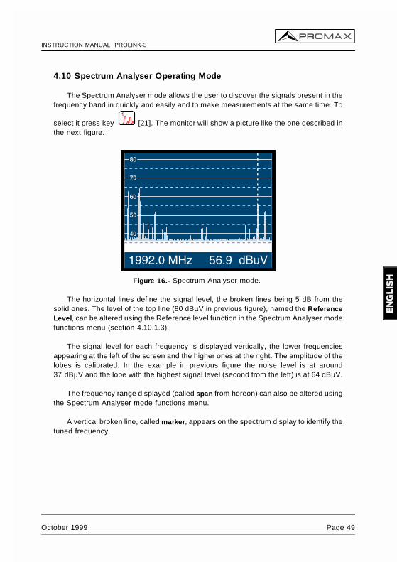
The Spectrum Analyser mode allows the user to discover the signals present in thefrequency band in quickly and easily and to make measurements at the same time. To
select it press key [21]. The monitor will show a picture like the one described inthe next figure.
Figure 16.- Spectrum Analyser mode.
The horizontal lines define the signal level, the broken lines being 5 dB from thesolid ones. The level of the top line (80 dBµV in previous figure), named the ReferenceLevel, can be altered using the Reference level function in the Spectrum Analyser modefunctions menu (section 4.10.1.3).
The signal level for each frequency is displayed vertically, the lower frequenciesappearing at the left of the screen and the higher ones at the right. The amplitude of thelobes is calibrated. In the example in previous figure the noise level is at around37 dBµV and the lobe with the highest signal level (second from the left) is at 64 dBµV.
The frequency range displayed (called span from hereon) can also be altered usingthe Spectrum Analyser mode functions menu.
A vertical broken line, called marker, appears on the spectrum display to identify thetuned frequency.
October 1999 Page 49
INSTRUCTION MANUAL PROLINK-3
One of the applications of the PROLINK-3 operating as Spectrum Analyser is in thesearch for the best orientation and position of the receiving antenna. This is particularlyimportant in UHF. Because such frequencies are involved, with wavelengths rangingfrom 35 cm to 65 cm, if the antenna is shifted only a few centimetres, the relationshipbetween the picture, chrominance and sound carrier frequencies change, affecting thequality of the picture in the receiver.
If there is an excess of sound carrier, tearing or 'moiré' may appear on the screendue to the frequency beats between the sound, chrominance and the picturefrequencies.
If there is a chrominance carrier defect, then the television colour amplifier mustfunction at maximum gain, which could result in noise appearing all over the televisionscreen with points of colour that disappear when the saturation control is reduced; in anextreme case, loss of colour may occur.
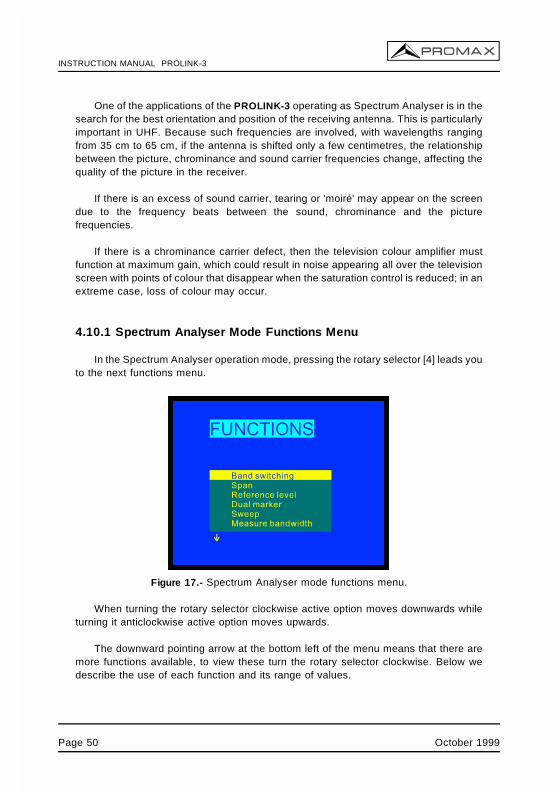
4.10.1 Spectrum Analyser Mode Functions Menu
In the Spectrum Analyser operation mode, pressing the rotary selector [4] leads youto the next functions menu.
Figure 17.- Spectrum Analyser mode functions menu.
When turning the rotary selector clockwise active option moves downwards whileturning it anticlockwise active option moves upwards.
The downward pointing arrow at the bottom left of the menu means that there aremore functions available, to view these turn the rotary selector clockwise. Below wedescribe the use of each function and its range of values.
Page 50 October 1999
INSTRUCTION MANUAL PROLINK-3
4.10.1.1 Band Switching
Permits to swicth from terrestrial (45-862 MHz) to satellite band (920-2150 MHz) andvice versa.
4.10.1.2 Span
This function enables selecting the displayed frequency range in Spectrum Analysermode between Full (the entire band), 500 MHz, 200 MHz, 100 MHz, 50 MHz, 32 MHz,16 MHz and 8 MHz (the latter two only in terrestrial bands).
To alter the span, select the functions menu, then turn the rotary selector [4] to theSpan function and press it. The screen will show a window with the spans which canbe selected. Turn the rotary selector [4] to the required span and activate it by pressingthe selector again.
In Full mode the measuring filter bandwidth used to display the spectrum is always1 MHz for terrestrial bands, and 4 MHz for satellite band. For the other spans you canselect the bandwidth using the Measure Bandwidth function on the same functionsmenu. (See section '4.10.1.10 Bandwidth of the Spectrum Measuring Filter').
4.10.1.3 Reference Level
The reference level corresponds to the level marked by the top horizontal lineappearing on the Spectrum Analyser mode screen. This function enables the referencelevel to be defined between 70 and 130 dBµV in 10 dB steps. The default referencelevel is 70 dBµV.
To alter the value of the reference level select the Spectrum Analyser modefunctions menu, turn the rotary selector [4] to select the Reference level function andpress it. The screen will show a window with the values which can be selected. Turn therotary selector [4] to the desired reference level and activate it by pressing the selectoragain.
October 1999 Page 51
INSTRUCTION MANUAL PROLINK-3
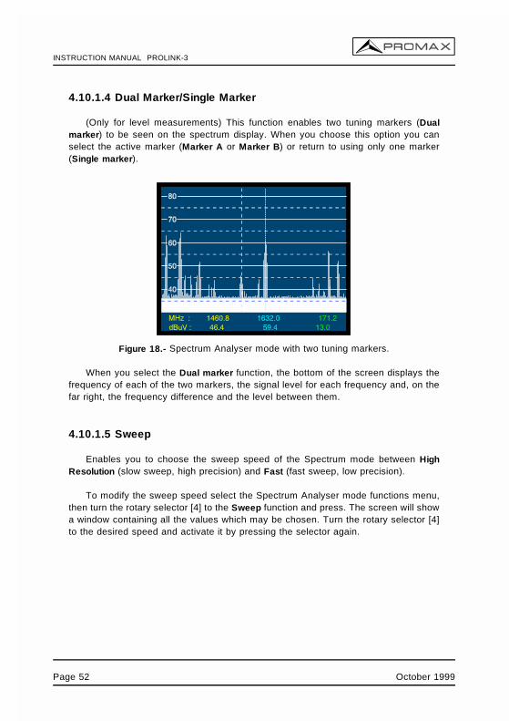
4.10.1.4 Dual Marker/Single Marker
(Only for level measurements) This function enables two tuning markers (Dualmarker) to be seen on the spectrum display. When you choose this option you canselect the active marker (Marker A or Marker B) or return to using only one marker(Single marker).
Figure 18.- Spectrum Analyser mode with two tuning markers.
When you select the Dual marker function, the bottom of the screen displays thefrequency of each of the two markers, the signal level for each frequency and, on thefar right, the frequency difference and the level between them.
4.10.1.5 Sweep
Enables you to choose the sweep speed of the Spectrum mode between HighResolution (slow sweep, high precision) and Fast (fast sweep, low precision).
To modify the sweep speed select the Spectrum Analyser mode functions menu,then turn the rotary selector [4] to the Sweep function and press. The screen will showa window containing all the values which may be chosen. Turn the rotary selector [4]to the desired speed and activate it by pressing the selector again.
Page 52 October 1999
INSTRUCTION MANUAL PROLINK-3
4.10.1.6 Reference Noise
(Only in C/N measurements). Permits to define the frequency where noise level willbe measured.
To modify the frequency where you want to measure noise level, accede to themenu functions and select the Reference noise function then, again in the Spectrummode, turn the rotary selector to place the marker on the frequency where you want to
measure the noise level or well, press key [31], current reference noise frequencywill be erased and using the keyboard introduce the new value. Finally accede to thefunctions menu again and execute the Carrier function so that you can tune new carrierfrequencies by turning the rotary selector.
4.10.1.7 Channel Bandwidth
(Only in Channel Power measurements). Permits to define channel bandwidth.
To modify the channel bandwidth, that is to say the power integration limits, accedeto the menu functions and select the Channel bandwidth function then, again in the
Spectrum mode, turn the rotary selector to modify it or well press key [31], currentchannel bandwidth will be erased and using the keyboard introduce the new value.Finally accede to the functions menu again and execute the Marker function so that youcan tune new carrier frequencies by turning the rotary selector.
4.10.1.8 Marker
(Only when measuring Channel power and after defining the Channel bandwidth).Permits to change the tuning frequency by means of the rotary selector.
4.10.1.9 Carrier
(Only when measuring C/N Referenced and after defining the Reference noise).Permits to change the tuning frequency by means of the rotary selector.
October 1999 Page 53
INSTRUCTION MANUAL PROLINK-3
4.10.1.10 Bandwidth of the Spectrum Measuring Filter (Measurebandwidth)
The frequency resolution of the Spectrum Analyser mode is determined by thebandwidth of the measuring filter when displaying the spectrum. This parameter isfundamental given the increasing density of channels present in all TV transmissionsystems.
To alter the bandwidth of measurement select the Spectrum Analyser functionsmenu, then turn the rotary selector [4] to the Measure bandwidth function and press.The screen will show a window displaying the values which can be selected. Turn therotary selector [4] to the chosen bandwidth and activate it by pressing the selectoragain.
The choice of bandwidth is:
Terrestrial channels: 230 kHz or 1 MHzSatellite channels: 230 kHz or 4 MHz
Filters with the greatest bandwidth (4 MHz y 1 MHz) allow you to take more stablemeasurements, as well as being able to distinguish between analogue and digitalcarriers. The 4 MHz filter is ideal for level measurements on the satellite band. The230 kHz filter is recommended for measuring terrestrial television, cable television andMMDS signals. It also allows you to identify smaller bandwidth signals such as NICAMsound carriers (terrestrial analogue channels), to detect the beacon signal on VSAT, theseparation between the audio FM carrier, and between the stereo sub-carriers intelevision.
4.10.1.11 Selecting the Channels Table (Channel set)
See 4.9.2.7 section.
4.10.1.12 Batteries and External Units Power Supply (Battery & Lnb)
See 4.9.2.3 section.
4.10.1.13 Exit
Exits from the Spectrum Analyser function menu.
Page 54 October 1999
INSTRUCTION MANUAL PROLINK-3
4.10.2 Selecting the Measurement Mode
The Spectrum Analyser mode permits to make different measurements at the sametime you see the signals present in the band. The types of measurements available are:
Terrestrial band - Analogue channels:Level Level measurement of the currently tuned carrier.C/N Video carrier to noise ratio referenced to a noise frequency
defined by the user through the Reference Noise function.
Terrestrial band - Digital channels:Channel power Integration method. It consists of scanning the entire channel,
calculating the contribution of each portion of the spectrum tothe whole.
C/N Referenced: Channel level to noise ratio referenced to a noisefrequency defined by the user through the Reference Noisefunction.
Satellite band - Analogue channels:Level Level measurement of the currently tuned carrier.C/N Video carrier to noise ratio referenced to a noise frequency
defined by the user through the Reference Noise function.
Satellite band - Digital channelsChannel power Integration method. C/N Referenced: Channel level to noise ratio referenced to a noise
frequency defined by the user through the Reference Noisefunction.
Like in the TV mode, to select the type of measure, press key [22] then turnthe rotary selector [4] until desired mode is marked and finally press the rotary selector
[4] or key [22] to activate the new measurement mode.
4.10.2.1 Measuring Carrier Levels (Level)
(Only for analogue channels). When selecting this mode on the lower part of theimage appears the tuned frequency (or channel) and the signal level at this frequency.If dual marker function is selected, tuned frequency and signal level are showed foreach one of the markers and, on the far right, the frequency difference and the levelbetween them.
October 1999 Page 55
INSTRUCTION MANUAL PROLINK-3
4.10.2.2 Measuring the Carrier / Noise ratio (C/N Referenced)
The Carrier/Noise ratio in Spectrum mode is always referenced to a noise frequencydefined by the user.
Imagine a situation like the one shown in the next figure: a digital channel (8 MHzBW) adjacent to an analogue channel. When measuring C/N for the digital channel inTV mode using the Auto setup, the analogue channel may interfere in the noisemeasurement (given that the noise level is measured at fnoise=ftuning - ½* Channel BW= 650 MHz - 4MHz = 646 MHz), so under this situation it is recommended to make themeasurement in Spectrum Analyser mode and to define manually the frequency wherewe want to measure noise (obviously a frequency where no signal is present); i.e. in thenext figure noise is defined to be measured at 655 MHz.
Figure 19.-Carrier to Noise measurement in Spectrum mode (digital channel).
To define the frequency to measure the noise, select the Reference noise functionin the Spectrum functions menu and press the rotary selector. Next, again in theSpectrum mode, turn the rotary selector to place the marker on the frequency where you
want to measure noise level or press key [31], current reference noise value willbe erased and using the keyboard introduce the new value. Finally accede to thefunctions menu again and execute the Carrier function so that you can tune new carrierfrequencies by turning the rotary selector.
When C/N measuring mode is selected, on the lower part of the image appears thetuned frequency/channel (Carr.), the noise frequency (Noise), the carrier Level (ifanalogue mode is selected) or the channel Power (if digital mode is selected) and thecarrier to noise ratio (C/N).
Page 56 October 1999
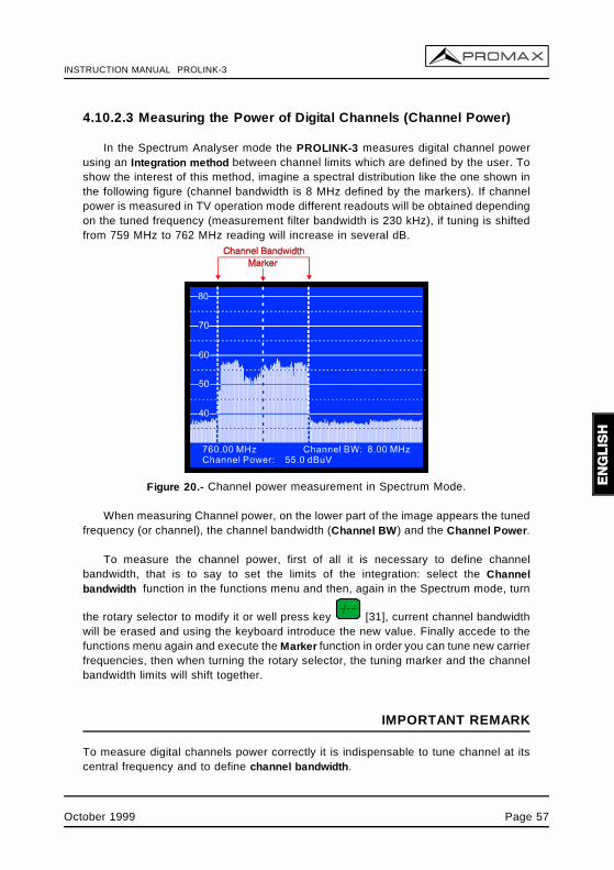
INSTRUCTION MANUAL PROLINK-3
4.10.2.3 Measuring the Power of Digital Channels (Channel Power)
In the Spectrum Analyser mode the PROLINK-3 measures digital channel powerusing an Integration method between channel limits which are defined by the user. Toshow the interest of this method, imagine a spectral distribution like the one shown inthe following figure (channel bandwidth is 8 MHz defined by the markers). If channelpower is measured in TV operation mode different readouts will be obtained dependingon the tuned frequency (measurement filter bandwidth is 230 kHz), if tuning is shiftedfrom 759 MHz to 762 MHz reading will increase in several dB.
Figure 20.- Channel power measurement in Spectrum Mode.
When measuring Channel power, on the lower part of the image appears the tunedfrequency (or channel), the channel bandwidth (Channel BW) and the Channel Power.
To measure the channel power, first of all it is necessary to define channelbandwidth, that is to say to set the limits of the integration: select the Channelbandwidth function in the functions menu and then, again in the Spectrum mode, turn
the rotary selector to modify it or well press key [31], current channel bandwidthwill be erased and using the keyboard introduce the new value. Finally accede to thefunctions menu again and execute the Marker function in order you can tune new carrierfrequencies, then when turning the rotary selector, the tuning marker and the channelbandwidth limits will shift together.
IMPORTANT REMARK
To measure digital channels power correctly it is indispensable to tune channel at itscentral frequency and to define channel bandwidth.
October 1999 Page 57
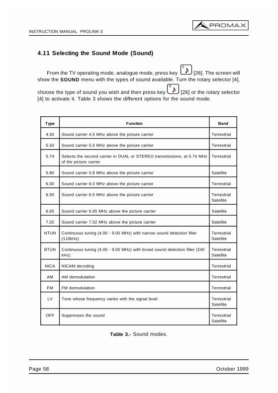
INSTRUCTION MANUAL PROLINK-3
4.11 Selecting the Sound Mode (Sound)
From the TV operating mode, analogue mode, press key [26]. The screen willshow the SOUND menu with the types of sound available. Turn the rotary selector [4],
choose the type of sound you wish and then press key [26] or the rotary selector[4] to activate it. Table 3 shows the different options for the sound mode.
Type Function Band
4.50 Sound carrier 4.5 MHz above the picture carrier Terrestrial
5.50 Sound carrier 5.5 MHz above the picture carrier Terrestrial
5.74 Selects the second carrier in DUAL or STEREO transmissions, at 5.74 MHzof the picture carrier
Terrestrial
5.80 Sound carrier 5.8 MHz above the picture carrier Satellite
6.00 Sound carrier 6.0 MHz above the picture carrier Terrestrial
6.50 Sound carrier 6.5 MHz above the picture carrier TerrestrialSatellite
6.65 Sound carrier 6.65 MHz above the picture carrier Satellite
7.02 Sound carrier 7.02 MHz above the picture carrier Satellite
NTUN Continuous tuning (4.00 - 9.00 MHz) with narrow sound detection filter(110kHz)
TerrestrialSatellite
BTUN Continuous tuning (4.00 - 9.00 MHz) with broad sound detection filter (240kHz)
TerrestrialSatellite
NICA NICAM decoding Terrestrial
AM AM demodulation Terrestrial
FM FM demodulation Terrestrial
LV Tone whose frequency varies with the signal level TerrestrialSatellite
OFF Suppresses the sound TerrestrialSatellite
Table 3.- Sound modes.
Page 58 October 1999
INSTRUCTION MANUAL PROLINK-3
When you select the NTUN (continuous tuning using a narrow detection filter) andBTUN (continuous tuning using a broad detection filter) options the screen displays awindow showing the frequency deviation of the sound carrier, this is variable between4.00 MHz and 9.00 MHz. To define it turn the rotary selector [4] to the desired frequencydeviation and press to validate.
When the LV function is selected, the speaker of the PROLINK-3 permits a tonewhose frequency depends on the level of the signal received. This is very useful wheninstalling antennas, since the user can locate the peak signal without having to lookcontinually at the monitor of the level meter.
When the NICAM option is selected, it is possible to measure the Bit Error Rate ofthe modulation. To obtain this measurement, from the TV operating mode, level
measurement, press key [2] in order to activate the mode of maximummeasurement information displayed on the screen (name assigned to memory, powersupply to external units, sound, colour system, TV standard, level andfrequency/channel). In the position relative to the type of Sound will appear theinformation about the type of NICAM according to:
Sound: Type + Error
Type = NICAM type:
"--": no NICAM is detected"du": dual NICAM"st": stereo NICAM"mo" mono NICAM
Error = indication of the bit error rate:
"E↓": error rate < 1e-5"E5": 1e-5 < error rate < 1e-4"E4": 1e-4 < error rate < 1e-3"E3": 1e-3 < error rate < 2.7 e-3"E↑": error rate > 2.7 e-3
Therefore, for example, the indication Sound: duE↓ has to be interpreted asNICAM sound is selected, the detected NICAM is dual and the error rate is below1 e-5.
October 1999 Page 59
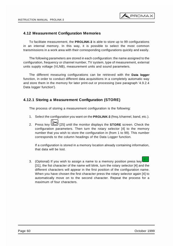
INSTRUCTION MANUAL PROLINK-3
4.12 Measurement Configuration Memories
To facilitate measurement, the PROLINK-3 is able to store up to 99 configurationsin an internal memory. In this way, it is possible to select the most commontransmissions in a work area with their corresponding configurations quickly and easily.
The following parameters are stored in each configuration: the name assigned to theconfiguration, frequency or channel number, TV system, type of measurement, externalunits supply voltage (VLNB), measurement units and sound parameters.
The different measuring configurations can be retrieved with the Data loggerfunction, in order to conduct different data acquisitions in a completely automatic wayand store them in the memory for later print-out or processing (see paragraph '4.9.2.4Data logger function').
4.12.1 Storing a Measurement Configuration (STORE)
The process of storing a measurement configuration is the following:
1. Select the configuration you want on the PROLINK-3 (freq./channel, band, etc.).
2. Press key [25] until the monitor displays the STORE screen. Check theconfiguration parameters. Then turn the rotary selector [4] to the memorynumber that you wish to store the configuration in (from 1 to 99). This numbercorresponds to the column headings of the Data Logger function.
If a configuration is stored in a memory location already containing information,that data will be lost.
3. (Optional) If you wish to assign a name to a memory position press key[31], the fist character of the name will blink, turn the rotary selector [4] and thedifferent characters will appear in the first position of the configuration name.When you have chosen the first character press the rotary selector again [4] toautomatically move on to the second character. Repeat the process for amaximum of four characters.
Page 60 October 1999
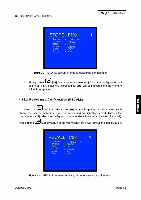
INSTRUCTION MANUAL PROLINK-3
Figure 21 .- STORE screen, storing a measuring configuration.
4. Finally, press [25] key or the rotary selector [4] and the configuration willbe stored. If any other key is pressed, an error will be indicated and the memorywill not be updated.
4.12.2 Retrieving a Configuration (RECALL)
Press the [25] key. The screen RECALL will appear on the monitor whichshows the different parameters of each measuring configuration stored. Turning therotary selector [4] select the configuration to be retrieved (a number between 1 and 99).
Pressing the [25] key again or the rotary selector [4] will retrieve the configuration.
Figure 22 .- RECALL screen, retrieving a measurement configuration.
October 1999 Page 61
INSTRUCTION MANUAL PROLINK-3
4.13 Direct Access to Functions
Keys [28] and [29] give direct access to any of the functions on the TVand Spectrum Analyser mode functions menus. To establish a relationship between thedirect access key and a function, access the functions menu, select the function you
wish to access directly and press key [28] or [29]. From then on when you
press key [28] or [29] the function will be accessed directly.
4.14 Printing Measurements and Memories
By connecting the instrument to a serial printer it is possible to obtain a printedreport of a sequence of measurements just at the moment they are taken, or later, ifthey are recorded with the Data logger function. This enables the user to keep a fileabout the state of the system and provide the documents related to the levelmeasurements for analysis purposes. The CI-23 portable printer is a PROLINK-3optional accessory.
The installation process consists of simply using the data transfer cable to connectthe printer to the RS-232C connector [37] on the PROLINK-3 (see section '4.14.1Handshake and control lines'). Switch off the power to both instruments beforeconnecting.
To print measurements select the Data logger function on the functions menu (seesection '4.9.2.4 Data Logger function'), access the configuration menu, activate the printfield (Print : On) and switch on the printer. From now on the printing process isequivalent to taking measurements. The following figure shows an example of printingtwo activated columns (memories 1 PM01 and 2 PM02) and two activated rows (testpoints 1 and 2).
Page 62 October 1999
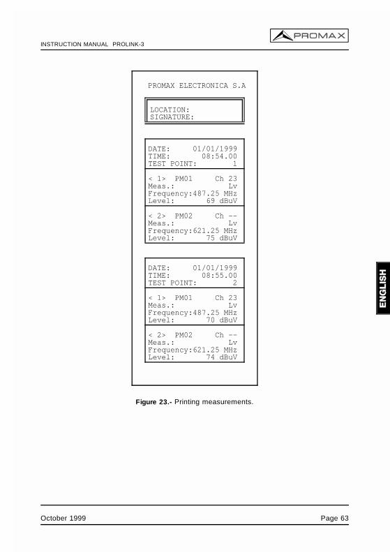
INSTRUCTION MANUAL PROLINK-3
PROMAX ELECTRONICA S.A
LOCATION:SIGNATURE:
DATE: 01/01/1999TIME: 08:54.00TEST POINT: 1
< 1> PM01 Ch 23Meas.: LvFrequency:487.25 MHzLevel: 69 dBuV
< 2> PM02 Ch --Meas.: LvFrequency:621.25 MHzLevel: 75 dBuV
DATE: 01/01/1999TIME: 08:55.00TEST POINT: 2
< 1> PM01 Ch 23Meas.: LvFrequency:487.25 MHzLevel: 70 dBuV
< 2> PM02 Ch --Meas.: LvFrequency:621.25 MHzLevel: 74 dBuV
Figure 23.- Printing measurements.
October 1999 Page 63
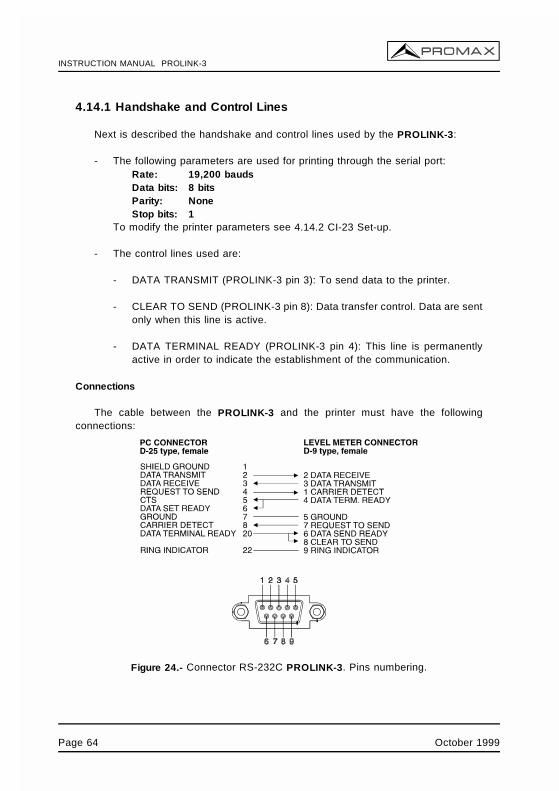
INSTRUCTION MANUAL PROLINK-3
4.14.1 Handshake and Control Lines
Next is described the handshake and control lines used by the PROLINK-3:
- The following parameters are used for printing through the serial port:Rate: 19,200 baudsData bits: 8 bitsParity: NoneStop bits: 1
To modify the printer parameters see 4.14.2 CI-23 Set-up.
- The control lines used are:
- DATA TRANSMIT (PROLINK-3 pin 3): To send data to the printer.
- CLEAR TO SEND (PROLINK-3 pin 8): Data transfer control. Data are sentonly when this line is active.
- DATA TERMINAL READY (PROLINK-3 pin 4): This line is permanentlyactive in order to indicate the establishment of the communication.
Connections
The cable between the PROLINK-3 and the printer must have the followingconnections:
Figure 24.- Connector RS-232C PROLINK-3. Pins numbering.
Page 64 October 1999
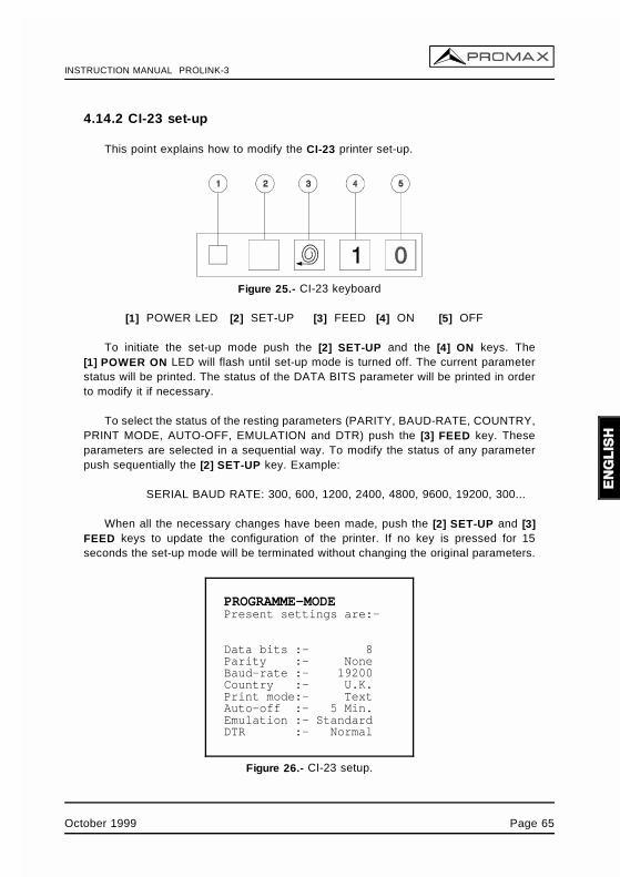
INSTRUCTION MANUAL PROLINK-3
4.14.2 CI-23 set-up
This point explains how to modify the CI-23 printer set-up.
Figure 25.- CI-23 keyboard
[1] POWER LED [2] SET-UP [3] FEED [4] ON [5] OFF
To initiate the set-up mode push the [2] SET-UP and the [4] ON keys. The[1] POWER ON LED will flash until set-up mode is turned off. The current parameterstatus will be printed. The status of the DATA BITS parameter will be printed in orderto modify it if necessary.
To select the status of the resting parameters (PARITY, BAUD-RATE, COUNTRY,PRINT MODE, AUTO-OFF, EMULATION and DTR) push the [3] FEED key. Theseparameters are selected in a sequential way. To modify the status of any parameterpush sequentially the [2] SET-UP key. Example:
SERIAL BAUD RATE: 300, 600, 1200, 2400, 4800, 9600, 19200, 300...
When all the necessary changes have been made, push the [2] SET-UP and [3]FEED keys to update the configuration of the printer. If no key is pressed for 15seconds the set-up mode will be terminated without changing the original parameters.
PROGRAMME-MODEPresent settings are:-
Data bits :- 8Parity :- NoneBaud-rate :- 19200Country :- U.K.Print mode:- TextAuto-off :- 5 Min.Emulation :- StandardDTR :- Normal
Figure 26.- CI-23 setup.
October 1999 Page 65

INSTRUCTION MANUAL PROLINK-3
Page 66 October 1999
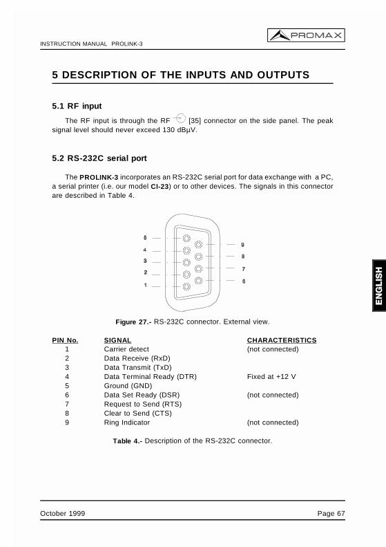
INSTRUCTION MANUAL PROLINK-3
5 DESCRIPTION OF THE INPUTS AND OUTPUTS
5.1 RF input
The RF input is through the RF [35] connector on the side panel. The peaksignal level should never exceed 130 dBµV.
5.2 RS-232C serial port
The PROLINK-3 incorporates an RS-232C serial port for data exchange with a PC,a serial printer (i.e. our model CI-23) or to other devices. The signals in this connectorare described in Table 4.
Figure 27.- RS-232C connector. External view.
PIN No. SIGNAL CHARACTERISTICS1 Carrier detect (not connected)2 Data Receive (RxD)3 Data Transmit (TxD)4 Data Terminal Ready (DTR) Fixed at +12 V5 Ground (GND)6 Data Set Ready (DSR) (not connected)7 Request to Send (RTS)8 Clear to Send (CTS)9 Ring Indicator (not connected)
Table 4.- Description of the RS-232C connector.
October 1999 Page 67
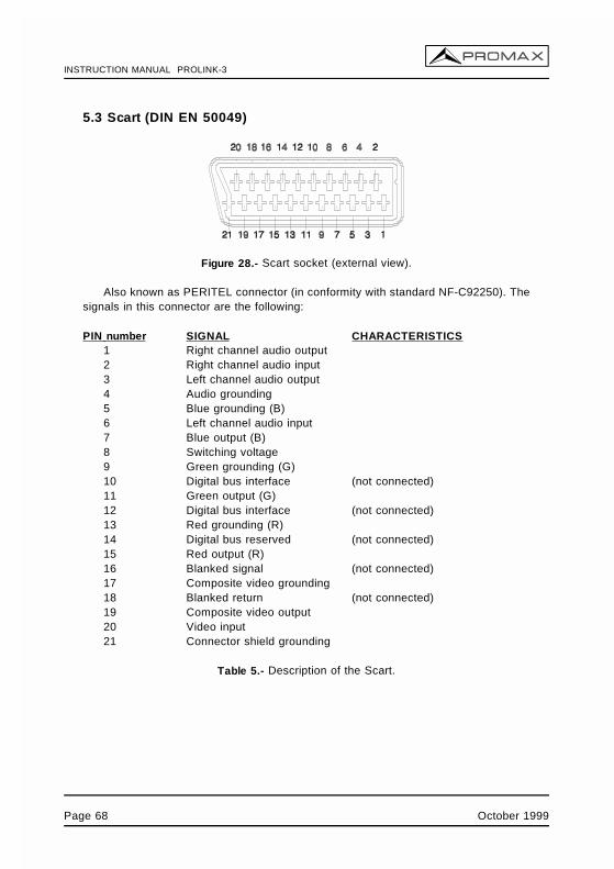
INSTRUCTION MANUAL PROLINK-3
5.3 Scart (DIN EN 50049)
Figure 28.- Scart socket (external view).
Also known as PERITEL connector (in conformity with standard NF-C92250). Thesignals in this connector are the following:
PIN number SIGNAL CHARACTERISTICS1 Right channel audio output2 Right channel audio input3 Left channel audio output4 Audio grounding5 Blue grounding (B)6 Left channel audio input7 Blue output (B)8 Switching voltage9 Green grounding (G)10 Digital bus interface (not connected)11 Green output (G)12 Digital bus interface (not connected)13 Red grounding (R)14 Digital bus reserved (not connected)15 Red output (R)16 Blanked signal (not connected)17 Composite video grounding18 Blanked return (not connected)19 Composite video output20 Video input21 Connector shield grounding
Table 5.- Description of the Scart.
Page 68 October 1999
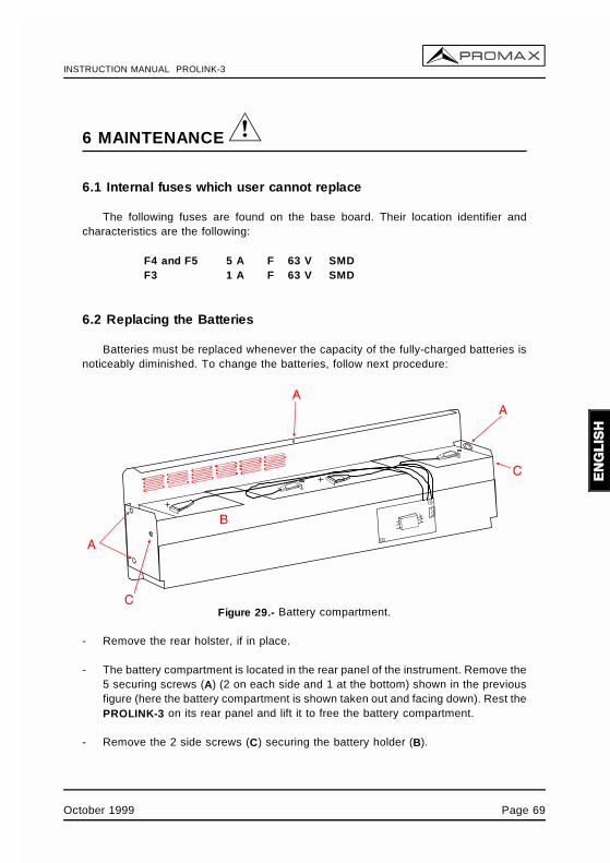
INSTRUCTION MANUAL PROLINK-3
6 MAINTENANCE
6.1 Internal fuses which user cannot replace
The following fuses are found on the base board. Their location identifier andcharacteristics are the following:
F4 and F5 5 A F 63 V SMDF3 1 A F 63 V SMD
6.2 Replacing the Batteries
Batteries must be replaced whenever the capacity of the fully-charged batteries isnoticeably diminished. To change the batteries, follow next procedure:
Figure 29.- Battery compartment.
- Remove the rear holster, if in place.
- The battery compartment is located in the rear panel of the instrument. Remove the5 securing screws (A) (2 on each side and 1 at the bottom) shown in the previousfigure (here the battery compartment is shown taken out and facing down). Rest thePROLINK-3 on its rear panel and lift it to free the battery compartment.
- Remove the 2 side screws (C) securing the battery holder (B).
October 1999 Page 69
INSTRUCTION MANUAL PROLINK-3
- Disconnect the battery terminals, remove the anti-humidity paper and replace thebatteries with two new ones of the same type.
IMPORTANT
The maximum period of time that the instrument can remain disconnected from thebatteries before loosing measurement configurations and stored data is 5 minutes.
- Replace the anti-humidity paper and connect the terminals to the new batteries.Remember to maintain the polarity of the terminals: red-positive, black-negative.
WARNINGAvoid any type of short circuit among the cables connected to the battery, since theresulting high current may cause serious damage to the instrument.
- Place and secure the battery holder (B) with the two screws (C).
- Insert the battery compartment into the back of the PROLINK-3 and secure with thefive screws (A).
- If you wish, replace the holster.
Page 70 October 1999
INSTRUCTION MANUAL PROLINK-3
6.3 Cleaning Recommendations
CAUTION
To clean the cover, take care the instrument is disconnected.
CAUTION
Do not use scented hydrocarbons or chlorized solvents. Such products may attack theplastics used in the construction of the cover.
The cover should be cleaned by means of a light solution of detergent and waterapplied with a soft cloth.
Dry thoroughly before using the system again.
CAUTION
Do not use for the cleaning of the front panel and particularly the viewfinders, alcoholor its derivatives, these products can attack the mechanical properties of the materialsand diminish their useful time of life.
October 1999 Page 71

INSTRUCTION MANUAL PROLINK-3
Page 72 October 1999
INSTRUCTION MANUAL PROLINK-3
TABLE OF CONTENTS
1 GENERAL . . . . . . . . . . . . . . . . . . . . . . . . . . . . . . . . . . . . . . . . . . . . . . . . . . 11.1 Description . . . . . . . . . . . . . . . . . . . . . . . . . . . . . . . . . . . . . . . . . . . . . 11.2 Specifications . . . . . . . . . . . . . . . . . . . . . . . . . . . . . . . . . . . . . . . . . . . 4
2 SAFETY RULES . . . . . . . . . . . . . . . . . . . . . . . . . . . . . . . . . . . . . . . . . . . . . 9
3 INSTALLATION . . . . . . . . . . . . . . . . . . . . . . . . . . . . . . . . . . . . . . . . . . . . . 113.1 Power Supply . . . . . . . . . . . . . . . . . . . . . . . . . . . . . . . . . . . . . . . . . . 11
3.1.1 Operation using the External DC Adapter . . . . . . . . . . . . . . . . . . 113.1.2 Operation using Batteries . . . . . . . . . . . . . . . . . . . . . . . . . . . . . 11
3.1.2.1 Battery Charging . . . . . . . . . . . . . . . . . . . . . . . . . . . . . . . 123.2 Installation and Start-up . . . . . . . . . . . . . . . . . . . . . . . . . . . . . . . . . . . 12
4 OPERATING INSTRUCTIONS . . . . . . . . . . . . . . . . . . . . . . . . . . . . . . . . . . 134.1 Description of the Controls and Elements . . . . . . . . . . . . . . . . . . . . . . 134.2 Adjustment of Volume and Monitor Parameters . . . . . . . . . . . . . . . . . . 204.3 Selecting the Operation Mode: TV / Spectrum Analyser . . . . . . . . . . . . 204.4 RF Band Selection: 45-862 MHz / 920-2150 MHz . . . . . . . . . . . . . . . . 204.5 Channel Tuning / Frequency Tuning . . . . . . . . . . . . . . . . . . . . . . . . . . 214.6 Automatic Transmission Search . . . . . . . . . . . . . . . . . . . . . . . . . . . . . 214.7 Selecting Analogue / Digital Mode . . . . . . . . . . . . . . . . . . . . . . . . . . . 224.8 External Units Power Supply (EXT. SUPPLY) . . . . . . . . . . . . . . . . . . . 224.9 TV Operating Mode . . . . . . . . . . . . . . . . . . . . . . . . . . . . . . . . . . . . . . 24
4.9.1 Selecting the Measurement Mode (MEASURE) . . . . . . . . . . . . . . 244.9.1.1 Measuring the Video Carrier Level (Level) . . . . . . . . . . . . . 25
4.9.1.1.1 On-screen Measurement Information . . . . . . . . . . . . . 274.9.1.1.2 Selecting TV Mode: TV, LV, SY (TV MODE) . . . . . . . 27
4.9.1.2 Measuring the Video / Audio Ratio (V/A) . . . . . . . . . . . . . . 294.9.1.3 Measuring the Carrier / Noise Ratio (C/N) . . . . . . . . . . . . . 294.9.1.4 Measuring the Power of Digital Channels (Channel power) . 32
4.9.2 TV Mode Functions Menu . . . . . . . . . . . . . . . . . . . . . . . . . . . . . 344.9.2.1 Selection of the RF Band: (Band switching) . . . . . . . . . . . . 354.9.2.2 Selection of the TV System and Standard
(System & Standard) . . . . . . . . . . . . . . . . . . . . . . . . . . . . 354.9.2.3 Batteries and External Units Power Supply (Battery & Lnb) . 374.9.2.4 Data Logger Function . . . . . . . . . . . . . . . . . . . . . . . . . . . . 38
4.9.2.4.1 Configuring the Data Logger Function . . . . . . . . . . . . 394.9.2.4.2 Selecting the Measurements to be Taken . . . . . . . . . 424.9.2.4.3 Taking Measurements . . . . . . . . . . . . . . . . . . . . . . . 424.9.2.4.4 Exiting the Data Logger Function . . . . . . . . . . . . . . . 434.9.2.4.5 Examples of Data Logger Function Applications . . . . . 43
.../...
INSTRUCTION MANUAL PROLINK-3
.../...
4.9.2.5 Clock . . . . . . . . . . . . . . . . . . . . . . . . . . . . . . . . . . . . . . . . 444.9.2.6 Input Video . . . . . . . . . . . . . . . . . . . . . . . . . . . . . . . . . . . 454.9.2.7 Selecting the Channels Table (Channel set) . . . . . . . . . . . . 454.9.2.8 Measurement Units . . . . . . . . . . . . . . . . . . . . . . . . . . . . . . 454.9.2.9 Power Off Mode (Manual power) . . . . . . . . . . . . . . . . . . . . 464.9.2.10 C/N setup . . . . . . . . . . . . . . . . . . . . . . . . . . . . . . . . . . . . 464.9.2.11 Channel Bandwidth (Channel BW) . . . . . . . . . . . . . . . . . . 464.9.2.12 LNB Local Oscillator Frequency (Lnb local osc) . . . . . . . . 474.9.2.13 Video Polarity . . . . . . . . . . . . . . . . . . . . . . . . . . . . . . . . . 474.9.2.14 NICAM Channel . . . . . . . . . . . . . . . . . . . . . . . . . . . . . . . 474.9.2.15 Search Level . . . . . . . . . . . . . . . . . . . . . . . . . . . . . . . . . 484.9.2.16 Beep . . . . . . . . . . . . . . . . . . . . . . . . . . . . . . . . . . . . . . . 484.9.2.17 Equipment Information . . . . . . . . . . . . . . . . . . . . . . . . . . 484.9.2.18 Exit . . . . . . . . . . . . . . . . . . . . . . . . . . . . . . . . . . . . . . . . 48
4.10 Spectrum Analyser Operating Mode . . . . . . . . . . . . . . . . . . . . . . . . . 494.10.1 Spectrum Analyser Mode Functions Menu . . . . . . . . . . . . . . . . 50
4.10.1.1 Band Switching . . . . . . . . . . . . . . . . . . . . . . . . . . . . . . . . 514.10.1.2 Span . . . . . . . . . . . . . . . . . . . . . . . . . . . . . . . . . . . . . . . 514.10.1.3 Reference Level . . . . . . . . . . . . . . . . . . . . . . . . . . . . . . . 514.10.1.4 Dual Marker/Single Marker . . . . . . . . . . . . . . . . . . . . . . . 524.10.1.5 Sweep . . . . . . . . . . . . . . . . . . . . . . . . . . . . . . . . . . . . . . 524.10.1.6 Reference Noise . . . . . . . . . . . . . . . . . . . . . . . . . . . . . . . 534.10.1.7 Channel Bandwidth . . . . . . . . . . . . . . . . . . . . . . . . . . . . . 534.10.1.8 Marker . . . . . . . . . . . . . . . . . . . . . . . . . . . . . . . . . . . . . . 534.10.1.9 Carrier . . . . . . . . . . . . . . . . . . . . . . . . . . . . . . . . . . . . . . 534.10.1.10 Bandwidth of the Spectrum Measuring Filter
(Measure bandwidth) . . . . . . . . . . . . . . . . . . . . . . . . . . . . 544.10.1.11 Selecting the Channels Table (Channel set) . . . . . . . . . . 544.10.1.12 Batteries and External Units Power Supply (Battery & Lnb) 544.10.1.13 Exit . . . . . . . . . . . . . . . . . . . . . . . . . . . . . . . . . . . . . . . 54
4.10.2 Selecting the Measurement Mode . . . . . . . . . . . . . . . . . . . . . . 554.10.2.1 Measuring Carrier Levels (Level) . . . . . . . . . . . . . . . . . . . 554.10.2.2 Measuring the Carrier / Noise ratio (C/N Referenced) . . . . 564.10.2.3 Measuring the Power of Digital Channels (Channel Power) 57
4.11 Selecting the Sound Mode (Sound) . . . . . . . . . . . . . . . . . . . . . . . . . . 584.12 Measurement Configuration Memories . . . . . . . . . . . . . . . . . . . . . . . 60
4.12.1 Storing a Measurement Configuration (STORE) . . . . . . . . . . . . . 604.12.2 Retrieving a Configuration (RECALL) . . . . . . . . . . . . . . . . . . . . 61
4.13 Direct Access to Functions . . . . . . . . . . . . . . . . . . . . . . . . . . . . . . . . 624.14 Printing Measurements and Memories . . . . . . . . . . . . . . . . . . . . . . . . 62
4.14.1 Handshake and Control Lines . . . . . . . . . . . . . . . . . . . . . . . . . 644.14.2 CI-23 set-up . . . . . . . . . . . . . . . . . . . . . . . . . . . . . . . . . . . . . . 65
.../...
INSTRUCTION MANUAL PROLINK-3
.../...
5 DESCRIPTION OF THE INPUTS AND OUTPUTS . . . . . . . . . . . . . . . . . . . . 675.1 RF input . . . . . . . . . . . . . . . . . . . . . . . . . . . . . . . . . . . . . . . . . . . . . . 675.2 RS-232C serial port . . . . . . . . . . . . . . . . . . . . . . . . . . . . . . . . . . . . . . 675.3 Scart (DIN EN 50049) . . . . . . . . . . . . . . . . . . . . . . . . . . . . . . . . . . . . 68
6 MAINTENANCE . . . . . . . . . . . . . . . . . . . . . . . . . . . . . . . . . . . . . . . . . . . . . 696.1 Internal fuses which user cannot replace . . . . . . . . . . . . . . . . . . . . . . . 696.2 Replacing the Batteries . . . . . . . . . . . . . . . . . . . . . . . . . . . . . . . . . . . 696.3 Cleaning Recommendations . . . . . . . . . . . . . . . . . . . . . . . . . . . . . . . . 71

INSTRUCTION MANUAL PROLINK-3