Embed Size (px)
Citation preview
I
Advancing the Limits of Dual Fuel Combustion
FREDRIK KÖNIGSSON
Licentiate thesis Department of Machine Design Royal Institute of Technology SE-100 44 Stockholm
TRITA – MMK 2012:14 ISSN 1400-1179
ISRN/KTH/MMK/R-12/14-SE ISBN 978-91-7501-427-2

II
TRITA – MMK 2012:14 ISSN 1400-1179 ISRN/KTH/MMK/R-12/14-SE ISBN 978-91-7501-427-2
Advancing The Limits of Dual Fuel Combustion Fredrik Königsson
Licentiate thesis
Academic thesis, which with the approval of Kungliga Tekniska Högskolan, will be presented for public review in fulfilment of the requirements for a Licentiate of Engineering in Machine Design. The public review is held at Kungliga Tekniska Högskolan, Brinellvägen in 83, room B319 Gladan, 15th of June at 10:00.
III
Abstract There is a growing interest in alternative transport fuels. There are two underlying reasons for this interest; the desire to decrease the environmental impact of transports and the need to compensate for the declining availability of petroleum. In the light of both these factors the Diesel Dual Fuel, DDF, engine is an attractive concept. The primary fuel of the DDF engine is methane, which can be derived both from renewables and from fossil sources. Methane from organic waste; commonly referred to as biomethane, can provide a reduction in greenhouse gases unmatched by any other fuel. The DDF engine is from a combustion point of view a hybrid between the diesel and the otto engine and it shares characteristics with both.
This work identifies the main challenges of DDF operation and suggests methods to overcome them. Injector tip temperature and pre-ignitions have been found to limit performance in addition to the restrictions known from literature such as knock and emissions of NOx and HC. HC emissions are especially challenging at light load where throttling is required to promote flame propagation. For this reason it is desired to increase the lean limit in the light load range in order to reduce pumping losses and increase efficiency. It is shown that the best results in this area are achieved by using early diesel injection to achieve HCCI/RCCI combustion where combustion phasing is controlled by the ratio between diesel and methane. However, even without committing to HCCI/RCCI combustion and the difficult control issues associated with it, substantial gains are accomplished by splitting the diesel injection into two and allocating most of the diesel fuel to the early injection. HCCI/RCCI and PPCI combustion can be used with great effect to reduce the emissions of unburned hydrocarbons at light load.
At high load, the challenges that need to be overcome are mostly related to heat. Injector tip temperatures need to be observed since the cooling effect of diesel flow through the nozzle is largely removed. Through investigation and modeling it is shown that the cooling effect of the diesel fuel occurs as the fuel resides injector between injections and not during the actual injection event. For this reason; fuel residing close to the tip absorbs more heat and as a result the dependence of tip temperature on diesel substitution rate is highly non-linear. The problem can be reduced greatly by improved cooling around the diesel injector. Knock and preignitions are limiting the performance of the engine and the behavior of each and how they are affected by gas quality needs to be determined. Based on experiences from this project where pure methane has been used as fuel; preignitions impose a stricter limit on engine operation than knock.

IV
Preface The material presented in this thesis was generated as part of an AVL-project to develop understanding of diesel dual fuel combustion. Partner in the project is Scania CV. The work was performed at the group of Internal Combustion Engines at the Royal Institute of Technology, Stockholm, Sweden. The project is partly funded by the Swedish Energy Agency. The thesis consists of an overview of dual fuel combustion and the challenges and opportunities associated with it. The overview is based on experimental results generated in the project but also on available literature.
The following people have contributed to the project and are gratefully acknowledged: Per Stålhammar, Hans-Erik Ångström, Andreas Cronhjort, Ernst Winklhofer, Richard Backman, Jonas Holmborn, Eric Olofsson, Stefan Olsson and last but not least PhD students, technical staff and project workers at the Internal Combustion Engine department.
V
Contents Abstract ................................................................................................................................................. III Preface ................................................................................................................................................... IV Outline & Readers guide ......................................................................................................................... 1 Appended papers ..................................................................................................................................... 2 Objectives ................................................................................................................................................ 3 1 Introduction ..................................................................................................................................... 3
1.1 The internal combustion engine .............................................................................................. 3 1.2 Fuels ........................................................................................................................................ 4
2 Emissions from combustion engines ............................................................................................... 7 2.1 Local emissions ....................................................................................................................... 7 2.2 Global emissions ..................................................................................................................... 8
3 Overview of methane engines ......................................................................................................... 9 3.1 Methane monofuel engines...................................................................................................... 9 3.2 Methane dual fuel engines ....................................................................................................... 9
4 The dual fuel engine ...................................................................................................................... 10 4.1 Introduction to DDF combustion ........................................................................................... 10 4.2 Literature on the dual fuel engine .......................................................................................... 12 4.3 Hydrocarbon emissions from the dual fuel engine ................................................................ 15 4.4 Dual fuel challenges .............................................................................................................. 18
5 Experimental setup ........................................................................................................................ 18 5.1 Engine .................................................................................................................................... 18 5.2 Control system ....................................................................................................................... 19 5.3 Instrumented diesel injector .................................................................................................. 20 5.4 Data acquisition ..................................................................................................................... 21
6 Results ........................................................................................................................................... 21 6.1 The DDF engine in relation to the SI and the CI engine ....................................................... 21 6.2 Dual fuel at light load ............................................................................................................ 24 6.3 Dual fuel at high load ............................................................................................................ 36
7 Summary and Outlook ................................................................................................................... 44 8 References ..................................................................................................................................... 46 Definitions/Abbreviations ..................................................................................................................... 51
1
Outline & Readers guide The thesis summarizes the experiences from the dual fuel project and can be read independently of the appended papers. The papers provide additional information about certain topics which are outlined in the Appended papers section. There are also references in the thesis text when additional information is available from the papers. The thesis is organized into the following chapters:
Chapter 1: Introduction The first chapter summarizes the history of the internal combustion engine. The section about fuels does the same for automotive fuels and discusses the driving forces behind the diversification of the fuel market that is currently taking place. Finally methane is put into perspective from an environmental and a supply point of view.
Chapter 2: Emissions from combustion engines Most of the development work performed within combustion engines is driven by emissions legislation. This chapter provides an overview of the legislated emissions and why they occur in combustion engines. Also included is a brief discussion of the two main global emissions which contribute to the greenhouse effect, CO2 and methane.
Chapter 3: Overview of methane engines Chapter 3 presents the main pathways currently available for propulsion when developing a methane road vehicle and introduces the diesel dual fuel engine.
Chapter 4: The Dual fuel engine This chapter provides an overview of the combustion process in the diesel dual fuel engine and outlines the main challenges. Also included is a literature survey and an overview of the effects of the different control parameters available.
Chapter 5: Experimental setup Details of the equipment used to record the data are found in this chapter.
Chapter 6: Results Firstly the dual fuel engine is put into context by comparing it to the SI and the CI engines with regards to emissions and efficiency.
At light load, dual fuel operation is a trade-off between throttling and combustion efficiency. Chapter 6 discusses this challenge and methods that can be used to increase the lean tolerance and reduce the need for throttling. These methods include injection strategies and unconventional combustion modes such as HCCI/RCCI and PPCI.
Heat related problems characterize dual fuel operation at high load. The main challenges are high injector tip temperature, preignitions and knock. Injector tip temperatures are treated thoroughly and a solution is proposed. Knock and preignitions in the DDF engine are introduced and discussed.
Chapter 7: Summary and Outlook A brief summary and suggestions for future work
2
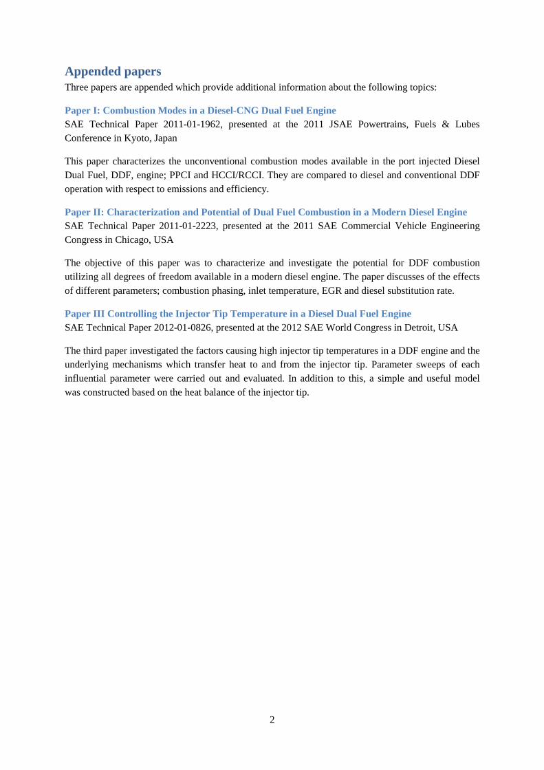
Appended papers Three papers are appended which provide additional information about the following topics:
Paper I: Combustion Modes in a Diesel-CNG Dual Fuel Engine SAE Technical Paper 2011-01-1962, presented at the 2011 JSAE Powertrains, Fuels & Lubes Conference in Kyoto, Japan
This paper characterizes the unconventional combustion modes available in the port injected Diesel Dual Fuel, DDF, engine; PPCI and HCCI/RCCI. They are compared to diesel and conventional DDF operation with respect to emissions and efficiency.
Paper II: Characterization and Potential of Dual Fuel Combustion in a Modern Diesel Engine SAE Technical Paper 2011-01-2223, presented at the 2011 SAE Commercial Vehicle Engineering Congress in Chicago, USA
The objective of this paper was to characterize and investigate the potential for DDF combustion utilizing all degrees of freedom available in a modern diesel engine. The paper discusses of the effects of different parameters; combustion phasing, inlet temperature, EGR and diesel substitution rate.
Paper III Controlling the Injector Tip Temperature in a Diesel Dual Fuel Engine SAE Technical Paper 2012-01-0826, presented at the 2012 SAE World Congress in Detroit, USA
The third paper investigated the factors causing high injector tip temperatures in a DDF engine and the underlying mechanisms which transfer heat to and from the injector tip. Parameter sweeps of each influential parameter were carried out and evaluated. In addition to this, a simple and useful model was constructed based on the heat balance of the injector tip.
3
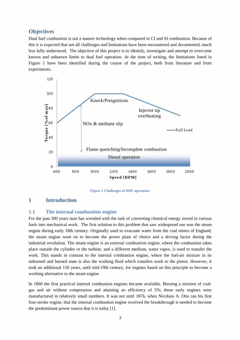
Objectives Dual fuel combustion is not a mature technology when compared to CI and SI combustion. Because of this it is expected that not all challenges and limitations have been encountered and documented, much less fully understood. The objective of this project is to identify, investigate and attempt to overcome known and unknown limits to dual fuel operation. At the time of writing, the limitations listed in Figure 1 have been identified during the course of the project, both from literature and from experiments.
Figure 1 Challenges of DDF operation.
1 Introduction
1.1 The internal combustion engine For the past 300 years man has wrestled with the task of converting chemical energy stored in various fuels into mechanical work. The first solution to this problem that saw widespread use was the steam engine during early 18th century. Originally used to evacuate water from the coal mines of England; the steam engine went on to become the power plant of choice and a driving factor during the industrial revolution. The steam engine is an external combustion engine, where the combustion takes place outside the cylinder or the turbine, and a different medium, water vapor, is used to transfer the work. This stands in contrast to the internal combustion engine, where the fuel-air mixture in its unburned and burned state is also the working fluid which transfers work to the piston. However, it took an additional 150 years, until mid-19th century, for engines based on this principle to become a working alternative to the steam engine.
In 1860 the first practical internal combustion engines became available. Burning a mixture of coal-gas and air without compression and attaining an efficiency of 5%; these early engines were manufactured in relatively small numbers. It was not until 1876, when Nicolaus A. Otto ran his first four-stroke engine, that the internal combustion engine received the breakthrough it needed to become the predominant power source that it is today [1].
0
20
40
60
80
100
120
600 800 1000 1200 1400 1600 1800 2000
Tor
qu
e [%
of
max
]
Speed [RPM]
Full Load
Injector tip overheating
Knock/Preignitions
Flame quenching/Incomplete combustion Diesel operation
NOx & methane slip
4
Recognizing that the greater the expansion of the post combustion gases, the greater the work transferred; attempts were made to increase the expansion ratio. Continuing on the theoretical work of Alphonse Beau de Rochas; James Atkinson constructed an engine where the expansion stroke was longer than the compression stroke. His engine, however, was plagued by mechanical problems and this course of action was more or less abandoned. Since then, for most practical purposes, the expansion and compression ratios have been linked and the desire to increase the expansion ratio translates into the need to increase the compression ratio.
The fuels available at the time did not permit compression ratios larger than 4 before the onset of knock, and while improvements were made to fuels, carburetors and ignition systems to help address this problem; Rudolf Diesel proposed a different approach [1]. In his patent from 1890 Diesel outlined a new type of combustion engine where the fuel was not added until after the compression and the temperature of the hot compressed air was sufficient to ignite the fuel. Rudolf Diesel improved on the concept by further increasing the compression ratio and due to his success in patenting his ideas; he is generally considered the inventor of the engine that bears his name. This new concept, the diesel engine, would permit much greater expansion ratios and thus greater efficiency. For the past hundred years wars, economic interests and lately emissions legislation have driven the development of both the otto and the diesel engine into their current respective forms. Advances has been made in many fields; from the materials used, casting methods, after treatment and engine geometry, to complex injection strategies, complex combustion modes and the software used for engine control.
1.2 Fuels In the early days of internal combustion engines, the fuels used were various; coal gas, coal powder, cleaning agents, lamp oil, kerosene and different petroleum distillates. As the demand from manufacturers of otto and diesel engines for high octane and high cetane fuels respectively coincided with the supply of cheap petroleum from USA and the Middle East; the choice of automotive fuels for most of the 20th century was in all essence reduced to two: gasoline and diesel fuel from petroleum feedstock.
The year of writing is 2012 and a combination of environmental concerns and supply constraints is driving the return to a diversified fuel market. The environmental concerns are can be summarized as the fear that our practice of burning fossil fuels and thus reintroducing the carbon stored in our planets crust during millennia into the atmosphere can cause a change in the climate.
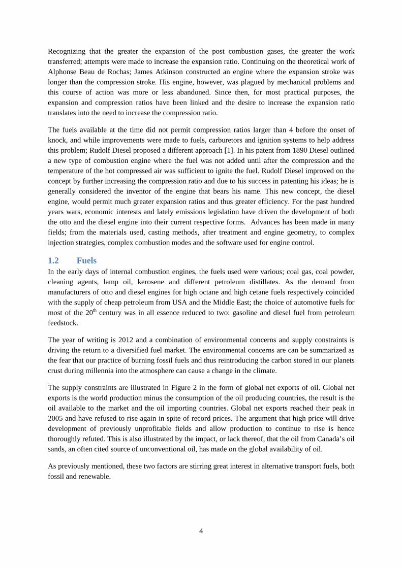
The supply constraints are illustrated in Figure 2 in the form of global net exports of oil. Global net exports is the world production minus the consumption of the oil producing countries, the result is the oil available to the market and the oil importing countries. Global net exports reached their peak in 2005 and have refused to rise again in spite of record prices. The argument that high price will drive development of previously unprofitable fields and allow production to continue to rise is hence thoroughly refuted. This is also illustrated by the impact, or lack thereof, that the oil from Canada’s oil sands, an often cited source of unconventional oil, has made on the global availability of oil.
As previously mentioned, these two factors are stirring great interest in alternative transport fuels, both fossil and renewable.
5
Figure 2 World net oil exports and annual average oil price for the time period 1980-2010 [2].
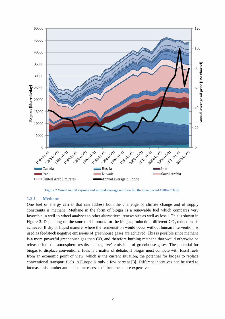
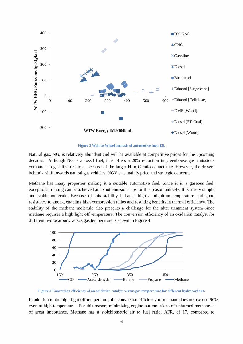
1.2.1 Methane One fuel or energy carrier that can address both the challenge of climate change and of supply constraints is methane. Methane in the form of biogas is a renewable fuel which compares very favorable in well-to-wheel analyses to other alternatives, renewables as well as fossil. This is shown in Figure 3. Depending on the source of biomass for the biogas production, different CO2 reductions is achieved. If dry or liquid manure, where the fermentation would occur without human intervention, is used as feedstock negative emissions of greenhouse gases are achieved. This is possible since methane is a more powerful greenhouse gas than CO2 and therefore burning methane that would otherwise be released into the atmosphere results in ‘negative’ emissions of greenhouse gases. The potential for biogas to displace conventional fuels is a matter of debate. If biogas must compete with fossil fuels from an economic point of view, which is the current situation, the potential for biogas to replace conventional transport fuels in Europe is only a few percent [3]. Different incentives can be used to increase this number and it also increases as oil becomes more expensive.
0
20
40
60
80
100
120
0
5000
10000
15000
20000
25000
30000
35000
40000
45000
50000
Ann
ual a
vera
ge o
il pr
ice
[USD
/bar
rel]
Exp
orts
[kba
rrel
s/da
y]
Canada Russia IranIraq Kuwait Saudi ArabiaUnited Arab Emirates Annual average oil price
6
Figure 3 Well-to-Wheel analysis of automotive fuels [3].
Natural gas, NG, is relatively abundant and will be available at competitive prices for the upcoming decades. Although NG is a fossil fuel, it is offers a 20% reduction in greenhouse gas emissions compared to gasoline or diesel because of the larger H to C ratio of methane. However, the drivers behind a shift towards natural gas vehicles, NGV:s, is mainly price and strategic concerns.
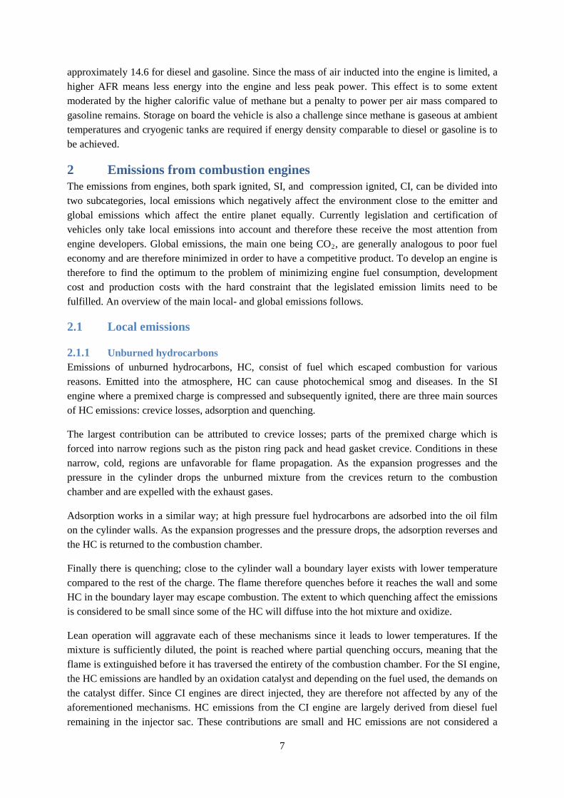
Methane has many properties making it a suitable automotive fuel. Since it is a gaseous fuel, exceptional mixing can be achieved and soot emissions are for this reason unlikely. It is a very simple and stable molecule. Because of this stability it has a high autoignition temperature and good resistance to knock, enabling high compression ratios and resulting benefits in thermal efficiency. The stability of the methane molecule also presents a challenge for the after treatment system since methane requires a high light off temperature. The conversion efficiency of an oxidation catalyst for different hydrocarbons versus gas temperature is shown in Figure 4.
Figure 4 Conversion efficiency of an oxidation catalyst versus gas temperature for different hydrocarbons.
In addition to the high light off temperature, the conversion efficiency of methane does not exceed 90% even at high temperatures. For this reason, minimizing engine out emissions of unburned methane is of great importance. Methane has a stoichiometric air to fuel ratio, AFR, of 17, compared to
-200
-100
0
100
200
300
400
0 100 200 300 400 500 600
WT
W G
HG
Em
issi
ons
[gC
O2/k
m]
WTW Energy [MJ/100km]
BIOGAS
CNG
Gasoline
Diesel
Bio-diesel
Ethanol [Sugar cane]
Ethanol [Cellulose]
DME [Wood]
Diesel [FT-Coal]
Diesel [Wood]
0
20
40
60
80
100
150 250 350 450CO Acetaldehyde Ethane Propane Methane
7
approximately 14.6 for diesel and gasoline. Since the mass of air inducted into the engine is limited, a higher AFR means less energy into the engine and less peak power. This effect is to some extent moderated by the higher calorific value of methane but a penalty to power per air mass compared to gasoline remains. Storage on board the vehicle is also a challenge since methane is gaseous at ambient temperatures and cryogenic tanks are required if energy density comparable to diesel or gasoline is to be achieved.
2 Emissions from combustion engines The emissions from engines, both spark ignited, SI, and compression ignited, CI, can be divided into two subcategories, local emissions which negatively affect the environment close to the emitter and global emissions which affect the entire planet equally. Currently legislation and certification of vehicles only take local emissions into account and therefore these receive the most attention from engine developers. Global emissions, the main one being CO2, are generally analogous to poor fuel economy and are therefore minimized in order to have a competitive product. To develop an engine is therefore to find the optimum to the problem of minimizing engine fuel consumption, development cost and production costs with the hard constraint that the legislated emission limits need to be fulfilled. An overview of the main local- and global emissions follows.
2.1 Local emissions
2.1.1 Unburned hydrocarbons Emissions of unburned hydrocarbons, HC, consist of fuel which escaped combustion for various reasons. Emitted into the atmosphere, HC can cause photochemical smog and diseases. In the SI engine where a premixed charge is compressed and subsequently ignited, there are three main sources of HC emissions: crevice losses, adsorption and quenching.
The largest contribution can be attributed to crevice losses; parts of the premixed charge which is forced into narrow regions such as the piston ring pack and head gasket crevice. Conditions in these narrow, cold, regions are unfavorable for flame propagation. As the expansion progresses and the pressure in the cylinder drops the unburned mixture from the crevices return to the combustion chamber and are expelled with the exhaust gases.
Adsorption works in a similar way; at high pressure fuel hydrocarbons are adsorbed into the oil film on the cylinder walls. As the expansion progresses and the pressure drops, the adsorption reverses and the HC is returned to the combustion chamber.
Finally there is quenching; close to the cylinder wall a boundary layer exists with lower temperature compared to the rest of the charge. The flame therefore quenches before it reaches the wall and some HC in the boundary layer may escape combustion. The extent to which quenching affect the emissions is considered to be small since some of the HC will diffuse into the hot mixture and oxidize.
Lean operation will aggravate each of these mechanisms since it leads to lower temperatures. If the mixture is sufficiently diluted, the point is reached where partial quenching occurs, meaning that the flame is extinguished before it has traversed the entirety of the combustion chamber. For the SI engine, the HC emissions are handled by an oxidation catalyst and depending on the fuel used, the demands on the catalyst differ. Since CI engines are direct injected, they are therefore not affected by any of the aforementioned mechanisms. HC emissions from the CI engine are largely derived from diesel fuel remaining in the injector sac. These contributions are small and HC emissions are not considered a
8
problem for CI engines. Hydrocarbon emissions from the dual fuel engine are treated further in Chapter 4.
2.1.2 Carbon monoxide Carbon monoxide, CO, is formed as an intermediate step in combustion of hydrocarbons. Failure of CO to oxidize into CO2 can depend on either unavailability of oxygen or too low temperatures. CO is toxic to humans, and can cause symptoms ranging from light headaches to death. In a stoichiometric engine, CO emissions will be substantial due to less than perfect mixing and local oxygen deficits. At lean conditions both the CI and the SI engine can suffer from CO emissions because of low temperatures. CO emissions are effectively handled by an oxidation catalyst.
2.1.3 Nitrogen oxides Mono-nitrogen oxides, NO and NO2, commonly referred to as NOx, are formed through various mechanisms where atmospheric nitrogen or nitrogen from the fuel is fused with oxygen with the aid of high temperatures. NOx emissions can cause respiratory diseases. At ground level NOx contributes to the formation of ozone while, paradoxically, it destroys the ozone at high altitudes damaging the ozone layer.
The most influential NOx producing mechanism in combustion engines is believed to be thermal NOx. This route was proposed by Zel’dovich in 1948 and has since been appended to. The extended Zel’dovich mechanism consists of three reversible reactions:
1. O• + N2 ←k1→ NO + N• 2. N• + O2 ←k2→ NO + O• 3. N• + OH ←k3→ NO + H•
The name thermal NOx refers to the high activation energy of the first, rate limiting reaction which makes this mechanism highly temperature dependent. The rate constants in the mechanism have been revised recently and substantially increased. According to current theory, thermal NOx is responsible for 90-95% of the NOx emissions from combustion engines [4].
Prompt NOx or Fenimore NOx is a mechanism where atmospheric N2 reacts with CH radicals. Due to the need for these radicals prompt NOx is dependent on locally fuel rich areas and decreases quickly at lean mixtures. At lean mixtures and high pressures, the first reaction of the Zel’dovich mechanism can be stabilized through collision with a third party so that N2O is formed instead of NO, the N2O is then oxidized to 2 NO molecules. Both Fenimore NOx and the N2O route are characterized by large uncertainties. Finally, there is the possibility of nitrogen bound in the fuel forming NO, however, engine fuels contain very little N2 and hence this contribution is considered irrelevant.
2.2 Global emissions
2.2.1 Carbon dioxide Carbon dioxide, CO2 is the inevitable byproduct of hydrocarbon combustion. It is an inert gas, not harmful to plants or animals. It is however a greenhouse gas. Burning fossil fuels, stored beneath the ground during past millennia increases the concentration of CO2 in the atmosphere. As the concentration of CO2 increases, more of the sun’s heat is retained potentially warming the planet and changing the climate.
9
2.2.2 Methane Methane, CH4, while a hydrocarbon by definition, it is also inert and does not contribute to smog production or respiratory diseases. However, methane is a very potent greenhouse gas and if not carefully addressed, methane slip from engines can nullify any environmental benefits of switching from gasoline or diesel.
3 Overview of methane engines
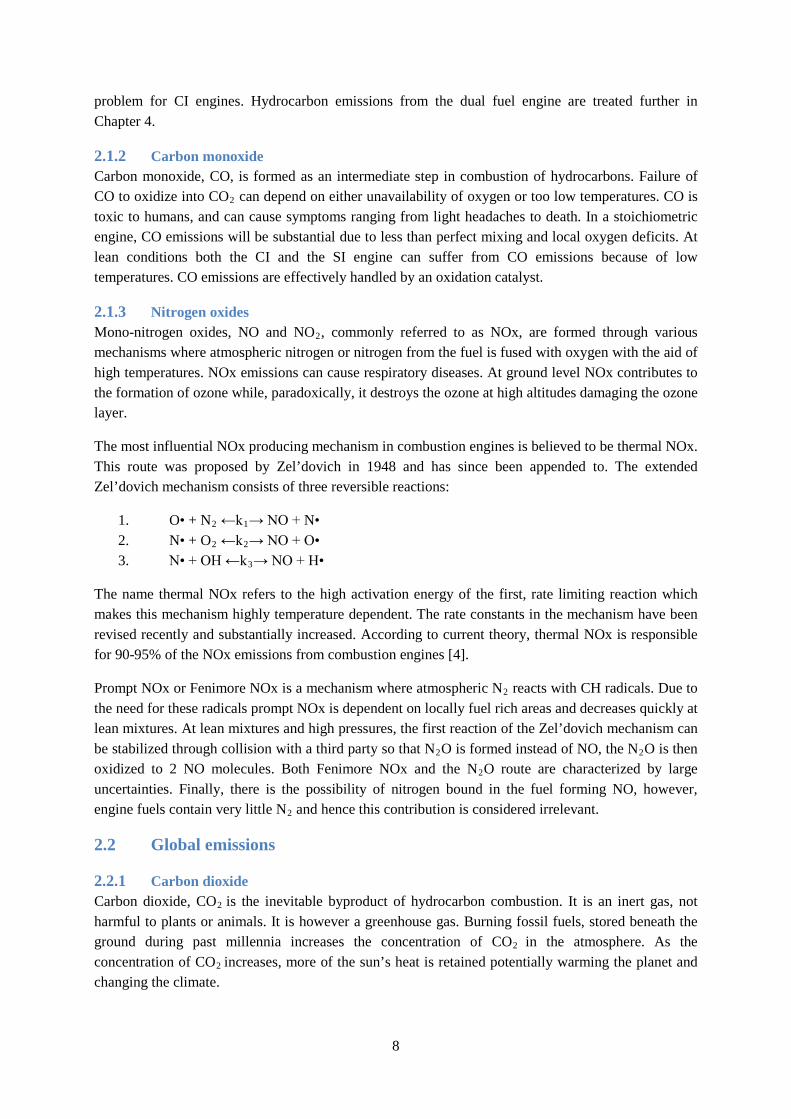
3.1 Methane monofuel engines Methane is mainly used in SI engines. In light duty applications, these engines are usually Bi-fuel engines; they must be able to operate on gasoline fuel as well. This limits the compression ratio and effectively limits the efficiency of the engine as well. For medium and heavy duty applications, SI gas engines are typically mono-fuel, meaning that they can be optimized for methane operation providing better efficiency. These engines still suffer from the known Achilles heel of the Otto engines; pumping losses and poor part load efficiency. The pumping losses can be addressed to some extent by running the engine lean and by adding EGR. This is explained in Figure 5.
Figure 5 Principal drawing explaining reductions in throttling losses by the addition of inert EGR [5].
Lean operation of an SI engine is the source of many complications since the three way catalyst can no longer be used to reduce NOx and a lot of strain is put on the ignition system.
Mono fuel compression ignition, CI, engines operating on methane is currently not feasible due to the high autoignition temperature and corresponding demand for compression ratio.
3.2 Methane dual fuel engines The solution to using methane in a CI engine is to introduce a pilot-fuel with higher cetane number which initiates combustion and ignites the methane, thus giving rise to the Diesel Dual Fuel, DDF, engine. Work is currently carried out both in the field of direct injected DDF, as well as port injected DDF.
Direct injected DDF involves a special DI injector which handles both the diesel and the methane fuel. A small pilot amount of diesel fuel is injected ahead of the main injection to raise the temperature and allow for ignition of the methane [6]. The methane is then injected and burns in a diffusion flame,
10
similar to diesel combustion. This concept enables unthrottled operation with little methane slip but particles and NOx present a problem. The system is also complex and expensive and it is not possible to run the vehicle on diesel only so fuel flexibility is lost.
In port injected DDF, the methane is injected into the intake manifold and is premixed with the air during induction and compression. A small diesel pilot is used to initiate combustion. The work presented in this thesis focuses solely on port injected DDF and henceforth this is what is referred to when the acronym DDF is used. Port injected DDF has the benefit of making conversion of existing vehicles relatively simple while maintaining full diesel capability in case methane is unavailable. Both of these factors are important when bringing the technology to market.
4 The dual fuel engine In this chapter, the port injected DDF engine is described in further detail. An introduction to DDF combustion is given, followed by an overview of the main challenges involved in dual fuel operation.
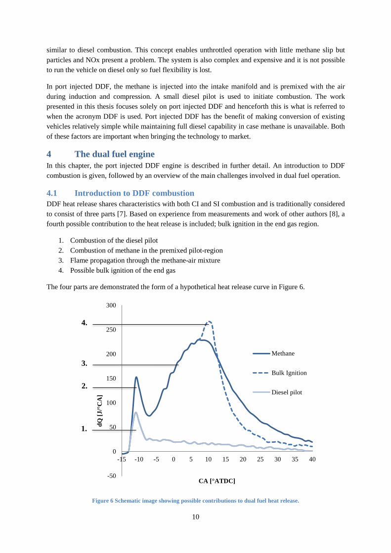
4.1 Introduction to DDF combustion DDF heat release shares characteristics with both CI and SI combustion and is traditionally considered to consist of three parts [7]. Based on experience from measurements and work of other authors [8], a fourth possible contribution to the heat release is included; bulk ignition in the end gas region.
1. Combustion of the diesel pilot 2. Combustion of methane in the premixed pilot-region 3. Flame propagation through the methane-air mixture 4. Possible bulk ignition of the end gas
The four parts are demonstrated the form of a hypothetical heat release curve in Figure 6.
Figure 6 Schematic image showing possible contributions to dual fuel heat release.
-50
0
50
100
150
200
250
300
-15 -10 -5 0 5 10 15 20 25 30 35 40
dQ [J
/°C
A]
CA [°ATDC]
Methane
Bulk Ignition
Diesel pilot
1.
2.
3.
4.
11
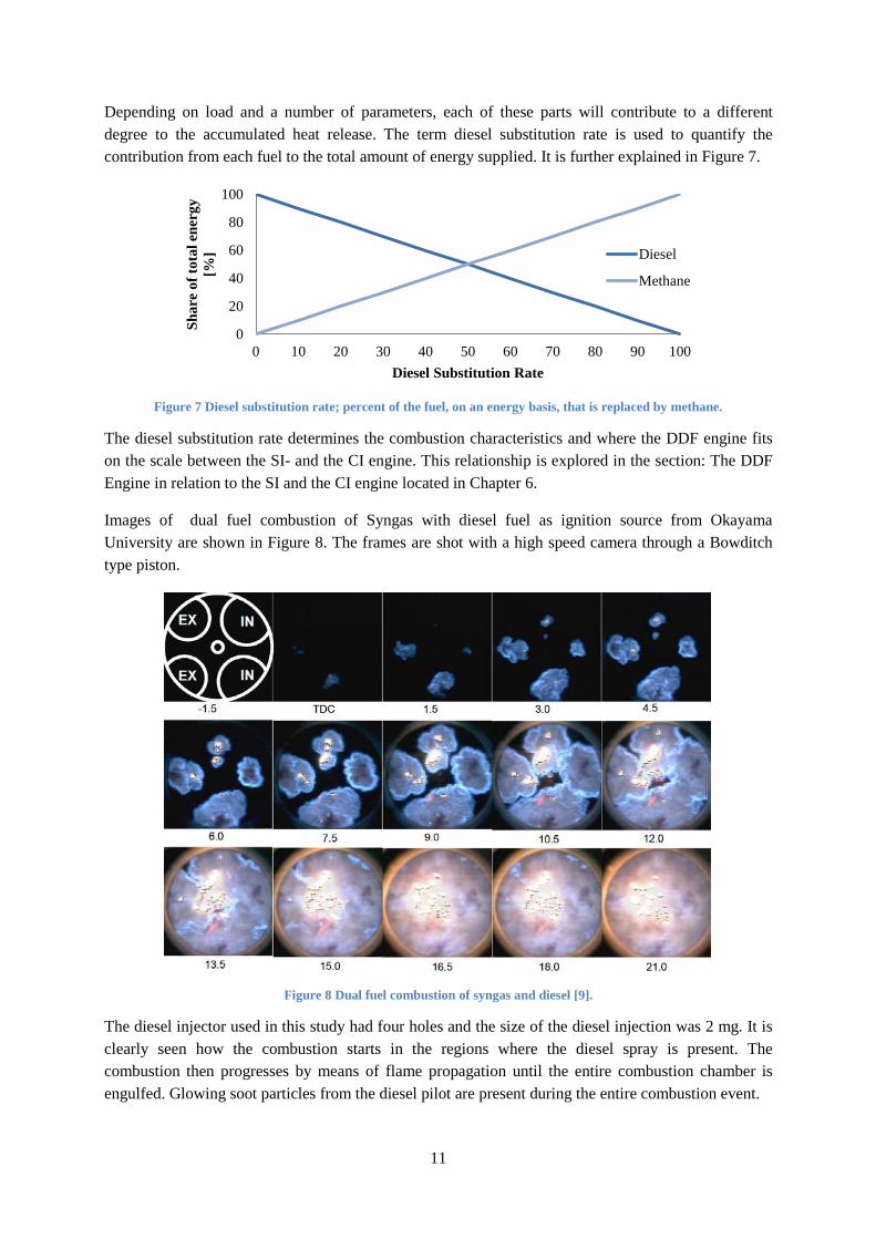
Depending on load and a number of parameters, each of these parts will contribute to a different degree to the accumulated heat release. The term diesel substitution rate is used to quantify the contribution from each fuel to the total amount of energy supplied. It is further explained in Figure 7.
Figure 7 Diesel substitution rate; percent of the fuel, on an energy basis, that is replaced by methane.
The diesel substitution rate determines the combustion characteristics and where the DDF engine fits on the scale between the SI- and the CI engine. This relationship is explored in the section: The DDF Engine in relation to the SI and the CI engine located in Chapter 6.
Images of dual fuel combustion of Syngas with diesel fuel as ignition source from Okayama University are shown in Figure 8. The frames are shot with a high speed camera through a Bowditch type piston.
Figure 8 Dual fuel combustion of syngas and diesel [9].
The diesel injector used in this study had four holes and the size of the diesel injection was 2 mg. It is clearly seen how the combustion starts in the regions where the diesel spray is present. The combustion then progresses by means of flame propagation until the entire combustion chamber is engulfed. Glowing soot particles from the diesel pilot are present during the entire combustion event.
0
20
40
60
80
100
0 10 20 30 40 50 60 70 80 90 100
Shar
e of
tota
l ene
rgy
[%]
Diesel Substitution Rate
Diesel
Methane
12
4.2 Literature on the dual fuel engine A lot of literature can be found pertaining to conversion of existing engines to dual fuel operation. A typical investigation includes a simple conversion of a diesel engine to dual fuel operation with the aid of port injectors or a gas mixer. The engine is operated and the effect of a few, easily controlled parameters, typically pilot amount, pilot timing, intake temperature, load and speed with respect to emissions and efficiency are investigated [10], [11], [12], [13], [14], [15], [16]. While these publications serve to confirm the general trends for DDF operation, they commonly lack depth and do not advance the understanding of the combustion process. The results in these studies are also quite specific to the engine setup used and may for this reason appear contradictory if this fact is not taken into account. The results of more general investigations are presented in [17], [7], [18]. However, most of the data presented is acquired at λ between 2 and 10, which is hardly relevant.
More in-depth investigations into the effect of air motion and gas supply method by means of optical observation through an endoscope are performed in [19], [20]. A high speed camera was used and each frame was converted to gray scale and the average luminosity across the entire frame was computed, resulting in a curve of luminosity versus crank angle. Considering the very strong luminosity of soot particles compared to that of a propagating flame and the limited field of view provided by an endoscope, the results could be seen as an indication of how much glowing soot transported in front of the window by the air motion instead of an indication of combustion quality. The authors also fail to provide information about λ during the tests, making the results impossible to put into context.
Several attempts to model dual fuel combustion have been made [21], [22], [23], [24], [25], [26], [27], [28], [29], [30], [31]. These publications all have in common that the models are validated against small datasets and no conclusions can be made regarding the validity over a wider range of conditions. Some of the models are validated for irrelevant operating conditions, [21], [23] while others show very poor congruence with measurements, [26], [22], [31]. Based on the available literature, it appears that dual fuel combustion is not sufficiently understood to enable predictive modeling.
The effects of the different control parameters available in the DDF engine as reported in the literature are summarized in the following section. Data from the current project is also presented to support the conclusions when necessary. The focus of the discussion will be on HC and NOx emissions.
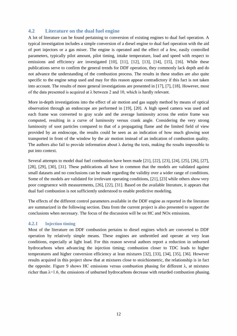
4.2.1 Injection timing Most of the literature on DDF combustion pertains to diesel engines which are converted to DDF operation by relatively simple means. These engines are unthrottled and operate at very lean conditions, especially at light load. For this reason several authors report a reduction in unburned hydrocarbons when advancing the injection timing; combustion closer to TDC leads to higher temperatures and higher conversion efficiency at lean mixtures [32], [33], [34], [35], [36]. However results acquired in this project show that at mixtures close to stoichiometric, the relationship is in fact the opposite. Figure 9 shows HC emissions versus combustion phasing for different λ, at mixtures richer than λ=1.6, the emissions of unburned hydrocarbons decrease with retarded combustion phasing.
13
Figure 9 HC emissions versus combustion phasing for different λ.
A likely explanation for this is that the temperature is higher during the expansion and that oxidation of HC returning from crevices is promoted. NOx emissions initially increase as injection timing is advances [33], [34], [32], [36], [35]. This is readily explained by the increased temperatures. Additional discussion regarding advanced combustion phasing is found in the appended paper no II. If the injection timing is advanced to the point that the combustion mode changes, the emissions trends will behave differently. This is discussed further in the section regarding unconventional combustion modes.
4.2.2 Diesel substitution rate The emissions of HC increase monotonously with increased diesel substitution rate and decreased amount of pilot injection [7], [35], [37]. At low λ the effect of crevices will lead to increased HC emissions when the amount of fuel supplied as a premixed charge increases in spite of efficient flame propagation. The emissions of NOx show a more complex behavior, they decrease for lean mixtures when the substitution rate is increased [7], [37] , [35]. The pilot zone is where the highest temperatures exist and most of the NOx is formed. At lower λ, however, the behavior is entirely the opposite, increased diesel substitution rate instead leads to more NOx. This is shown in Figure 19 and further discussed in connection to the figure and also in the appended paper no II. At high substitution rates soot formation is not considered a problem, but it remains to be demonstrated whether future emissions levels can be reached without a DPF.
4.2.3 Inlet temperature Increased inlet temperature enhances the flame propagation and reduces the emissions of HC and CO [7]. Predictably it also leads to higher emissions of NOx. High inlet temperature increases the likelihood of knock and preignition at high load and it is therefore something which can be utilized primarily at light load to reduce the amount of throttling needed. Results from test runs with raised intake temperature and further discussion is located in the appended paper no II.
4.2.4 EGR EGR lowers the compression temperature and dilutes the mixture; both these factors affect combustion efficiency negatively. For this reason CO and HC emissions increase. It also lowers the combustion temperature which drastically reduces the formation of NOx and reduces the risk of preignitions [32], [38], [39]. The effect of EGR on pre-ignitions has also been noticed during the course of this project
4 6 8 10 12
1000
2000
3000
4000
5000
6000
CA50 [° ATDC]
HC
[ppm
C]
Lambda = 1.2Lambda = 1.4Lambda = 1.6Lambda = 1.8
14
and cooled EGR may be a tool needed to reach the desired power density. Hot EGR combines the NOx reducing effect with the improved flame propagation from high inlet temperature, allowing a simultaneous reduction of HC, CO and NOx [33]. The use of EGR to reach stoichiometric conditions while minimizing throttling loss is also a strong possibility in the DDF engine thus enabling a very cost efficient after treatment system through the use of a three-way-catalyst [38]. The EGR tolerance is very large compared to an SI engine due to the powerful ignition source. EGR as a tool to reach stoichiometry is discussed further in the appended paper no II.
4.2.5 Diesel common rail pressure The diesel common rail pressure has small effect on combustion with the notable exception that reduced common rail pressure helps facilitate reliable pilot injection at operating points with substantial throttling. This is discussed further in the chapter named Dual fuel at light load.
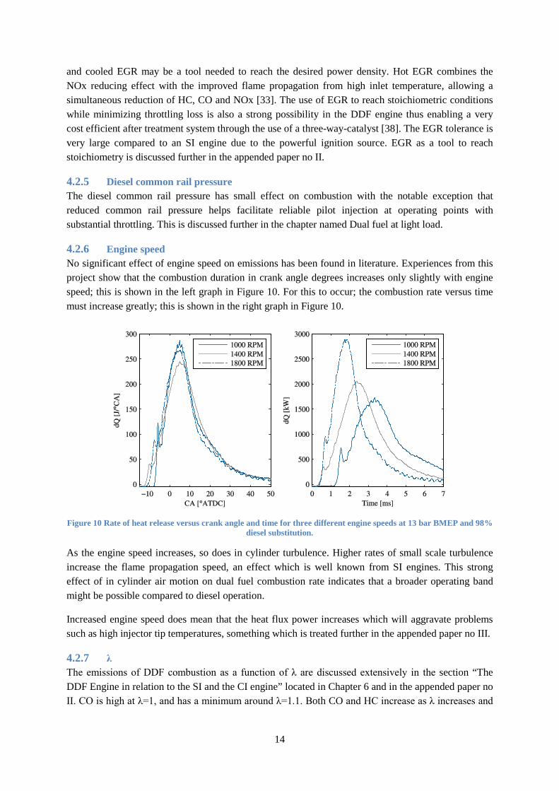
4.2.6 Engine speed No significant effect of engine speed on emissions has been found in literature. Experiences from this project show that the combustion duration in crank angle degrees increases only slightly with engine speed; this is shown in the left graph in Figure 10. For this to occur; the combustion rate versus time must increase greatly; this is shown in the right graph in Figure 10.
Figure 10 Rate of heat release versus crank angle and time for three different engine speeds at 13 bar BMEP and 98% diesel substitution.
As the engine speed increases, so does in cylinder turbulence. Higher rates of small scale turbulence increase the flame propagation speed, an effect which is well known from SI engines. This strong effect of in cylinder air motion on dual fuel combustion rate indicates that a broader operating band might be possible compared to diesel operation.
Increased engine speed does mean that the heat flux power increases which will aggravate problems such as high injector tip temperatures, something which is treated further in the appended paper no III.
4.2.7 λ The emissions of DDF combustion as a function of λ are discussed extensively in the section “The DDF Engine in relation to the SI and the CI engine” located in Chapter 6 and in the appended paper no II. CO is high at λ=1, and has a minimum around λ=1.1. Both CO and HC increase as λ increases and
15
combustion becomes colder. NOx has a maximum around λ= 1.2 for high substitution rates and decrease with higher λ. The same trends are confirmed in literature [7], [40], [34], [17].
4.2.8 Coolant temperature A cold engine causes more heat to be transferred from the gas to the combustion chamber walls; this reduces combustion temperatures and increases CO and HC while emissions of NOx decrease. As the engine heats up, the influence of post oxidation of HC and CO becomes greater. Of minor effect is also the fact that the piston expands and crevice volumes decrease [41].
4.2.9 Valve timing Since the DDF engine is premixed, variable valve timing can be used to reduce the pumping losses from throttling at light load. However variable valve timing has not yet made its way into production diesel engines and is therefore unlikely to be available to the DDF engine. This is reflected in the literature; not a lot of work is presented pertaining to this subject.
Negative exhaust valve overlap has been used successfully to reduce engine out HC emissions [42]. An exhaust valve timing advance of 19°CA resulted in a reduction of HC emissions by approximately 25% at high substitution rates and λ=2, and an advance of 38°CA resulted in a 50% reduction of HC. For the 38°CA advance the in-cylinder temperature increased by 20°C which can be expected to improve combustion efficiency and probably accounts for some of the 50% reduction. However since the 19°CA advance had the same in-cylinder temperature at IVC, the reduction in HC could be from trapping HC emerging from crevices late during the expansion and during the blowdown. Negative valve overlap with fixed cams would likely severely limit maximum load due to knock and is for this reason unlikely to be utilized in production.
4.2.10 Summary of influence of control parameters A rule of thumb is that parameter changes which increase in combustion temperature decrease HC and CO emissions but increase the emissions of NOx. Hot EGR is the exception to the rule since it has the potential to simultaneously reduce HC, CO and NOx.
4.3 Hydrocarbon emissions from the dual fuel engine The emissions of unburned hydrocarbons, HC, are the real Achilles heel of the DDF engine since methane is unreactive and particularly difficult to handle by the after treatment system. With a conversion efficiency of 90% for a methane oxidation catalyst, even at temperatures above 500°C; this imposes very strict limits on engine out HC. This is in contrast to the gasoline engine where HC and CO are problematic only during cold starts before catalyst light off. For SI engines, 6 sources of HC are identified [43].
1. Combustion chamber crevices 2. Absorption and desorption of fuel in oil 3. Absorption and desorption of fuel in deposits 4. Flame quenching, both wall and bulk 5. Liquid fuel in the cylinder, bad preparation 6. Exhaust valve leakage
Of these six mechanisms, only some are applicable to DDF operation. Mechanism two does not contribute to HC emissions since methane is practically insoluble in oil [44]. Absorption in deposits, mechanism three, is considered small but cannot be ruled out. Bulk quenching of the flame cannot be
16
allowed for reasons of emissions, drivability and efficiency. The control strategy must be such that sufficient margin towards misfire exists. The contribution from wall quenching to HC emissions is considered small since most of the fuel diffuses out of the boundary layer and into the burned charge and oxidizes [1]. However, since the dual fuel engine is operated mostly at lean conditions and methane is resistant to oxidation the fuel that diffuses into the burned zone is subject to lower temperatures and might escape oxidation. Hence the contribution from mechanism four is unknown. Mechanisms five and six are ruled out since methane is a gaseous fuel which gives good preparation and exhaust valve leakage should not be a factor in a modern engine in good condition.
HC emissions from diesel engines are discussed in [1] and three sources are identified:
1. Overmixing of fuel and air during ignition delay 2. Overriching of the mixture beyond stoichiometric 3. Fuel escaping from nozzle sac during expansion
Mechanism one is ruled out during dual fuel operation since the diesel is injected into a homogenous mixture of methane and air and no overly lean zones should exist. Mechanism two is also not an issue, since there is little reason to run the DDF engine rich. In the SI engine, rich operation is used to cool the charge from the vaporization energy of the fuel or to increase the power through increased flame speed. Since methane is gaseous cooling from enrichment is not feasible, also the highest flame speed of methane occurs at stoichiometry and thus the motivation for rich operation is removed. The remaining mechanism, number three, occurs in the DDF engine but since the HC from the nozzle sac consists of diesel, which is much easier to oxidize in a catalyst, this is not considered an issue. Hence, mechanisms contributing to HC emissions from DDF operation are, listed in perceived order of importance:
1. Combustion chamber crevices 2. Flame quenching, both wall and bulk 3. Absorption and desorption in deposits 4. Fuel escaping from nozzle sac during expansion
Of these four, category one is considered most influential followed by category two. Category three is likely small and the HC from category four is not methane but diesel and therefore presents a much lesser problem.
4.3.1 Hydrocarbon emissions from crevices Crevices are narrow regions of the combustion chamber where heat transfer to the surrounding material prevents flame propagation. In an SI engine, the most influential crevices and their approximate contribution to the total hydrocarbons from crevices, crevice-HC, are [1]:
• Ring pack crevices, the volume in topland and second land above the first and second compression rings. These account for 80% of crevice-HC.
• Head gasket crevice, 13% of crevice-HC. • Spark plug threads and volume around center electrode, 5% of crevice-HC. • Other, including valve seat crevices, 2%.
In the Scania engine used in this project; the cylinder head seals tightly against the cylinder liner and therefore no head gasket crevice exists. Naturally the engine also lacks a spark plug but the slit around
17
the diesel injector tip likely contributes in a similar manner. For this reason the ring pack crevices, and most importantly the topland volume, are likely the most influential in the dual fuel engine.
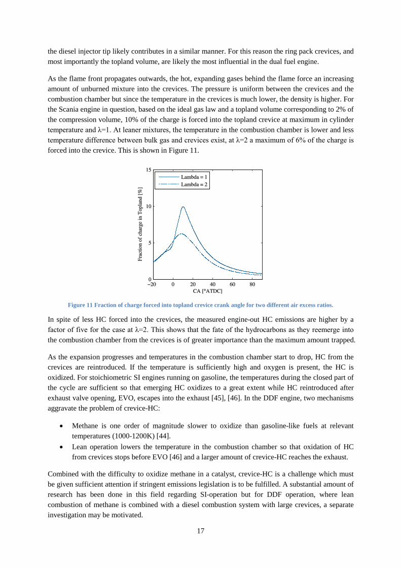
As the flame front propagates outwards, the hot, expanding gases behind the flame force an increasing amount of unburned mixture into the crevices. The pressure is uniform between the crevices and the combustion chamber but since the temperature in the crevices is much lower, the density is higher. For the Scania engine in question, based on the ideal gas law and a topland volume corresponding to 2% of the compression volume, 10% of the charge is forced into the topland crevice at maximum in cylinder temperature and λ=1. At leaner mixtures, the temperature in the combustion chamber is lower and less temperature difference between bulk gas and crevices exist, at λ=2 a maximum of 6% of the charge is forced into the crevice. This is shown in Figure 11.
Figure 11 Fraction of charge forced into topland crevice crank angle for two different air excess ratios.
In spite of less HC forced into the crevices, the measured engine-out HC emissions are higher by a factor of five for the case at λ=2. This shows that the fate of the hydrocarbons as they reemerge into the combustion chamber from the crevices is of greater importance than the maximum amount trapped.
As the expansion progresses and temperatures in the combustion chamber start to drop, HC from the crevices are reintroduced. If the temperature is sufficiently high and oxygen is present, the HC is oxidized. For stoichiometric SI engines running on gasoline, the temperatures during the closed part of the cycle are sufficient so that emerging HC oxidizes to a great extent while HC reintroduced after exhaust valve opening, EVO, escapes into the exhaust [45], [46]. In the DDF engine, two mechanisms aggravate the problem of crevice-HC:
• Methane is one order of magnitude slower to oxidize than gasoline-like fuels at relevant temperatures (1000-1200K) [44].
• Lean operation lowers the temperature in the combustion chamber so that oxidation of HC from crevices stops before EVO [46] and a larger amount of crevice-HC reaches the exhaust.
Combined with the difficulty to oxidize methane in a catalyst, crevice-HC is a challenge which must be given sufficient attention if stringent emissions legislation is to be fulfilled. A substantial amount of research has been done in this field regarding SI-operation but for DDF operation, where lean combustion of methane is combined with a diesel combustion system with large crevices, a separate investigation may be motivated.
18
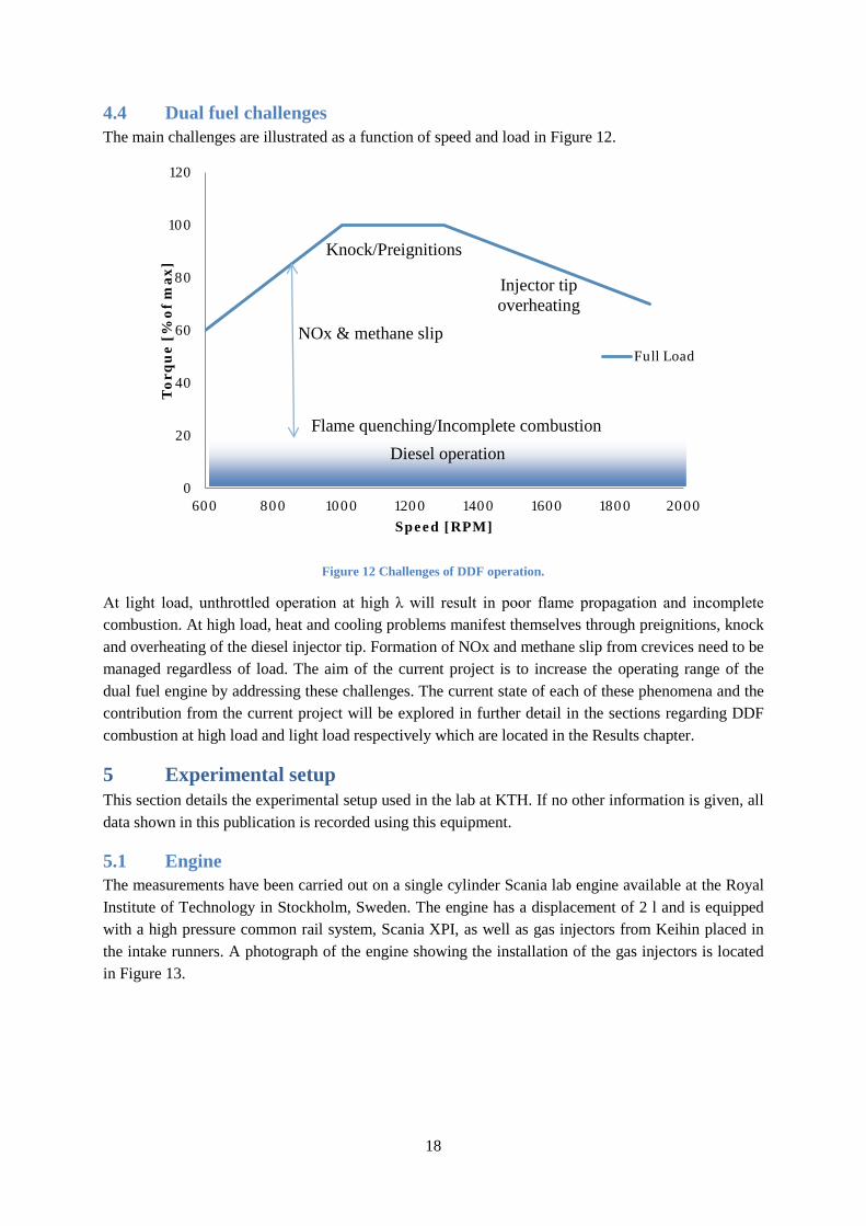
4.4 Dual fuel challenges The main challenges are illustrated as a function of speed and load in Figure 12.
Figure 12 Challenges of DDF operation.
At light load, unthrottled operation at high λ will result in poor flame propagation and incomplete combustion. At high load, heat and cooling problems manifest themselves through preignitions, knock and overheating of the diesel injector tip. Formation of NOx and methane slip from crevices need to be managed regardless of load. The aim of the current project is to increase the operating range of the dual fuel engine by addressing these challenges. The current state of each of these phenomena and the contribution from the current project will be explored in further detail in the sections regarding DDF combustion at high load and light load respectively which are located in the Results chapter.
5 Experimental setup This section details the experimental setup used in the lab at KTH. If no other information is given, all data shown in this publication is recorded using this equipment.
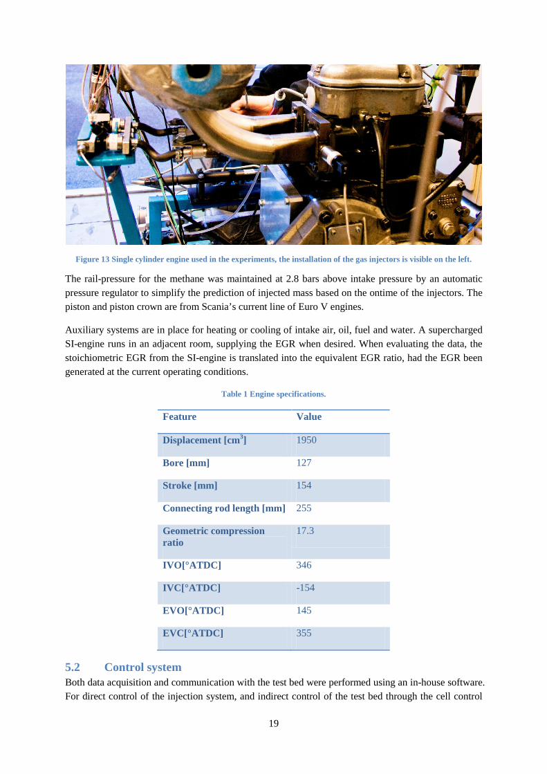
5.1 Engine The measurements have been carried out on a single cylinder Scania lab engine available at the Royal Institute of Technology in Stockholm, Sweden. The engine has a displacement of 2 l and is equipped with a high pressure common rail system, Scania XPI, as well as gas injectors from Keihin placed in the intake runners. A photograph of the engine showing the installation of the gas injectors is located in Figure 13.
0
20
40
60
80
100
120
600 800 1000 1200 1400 1600 1800 2000
Tor
qu
e [%
of
max
]
Speed [RPM]
Full Load
Injector tip overheating
Knock/Preignitions
Flame quenching/Incomplete combustion Diesel operation
NOx & methane slip
19
Figure 13 Single cylinder engine used in the experiments, the installation of the gas injectors is visible on the left.
The rail-pressure for the methane was maintained at 2.8 bars above intake pressure by an automatic pressure regulator to simplify the prediction of injected mass based on the ontime of the injectors. The piston and piston crown are from Scania’s current line of Euro V engines.
Auxiliary systems are in place for heating or cooling of intake air, oil, fuel and water. A supercharged SI-engine runs in an adjacent room, supplying the EGR when desired. When evaluating the data, the stoichiometric EGR from the SI-engine is translated into the equivalent EGR ratio, had the EGR been generated at the current operating conditions.
Table 1 Engine specifications.
Feature Value
Displacement [cm3] 1950
Bore [mm] 127
Stroke [mm] 154
Connecting rod length [mm] 255
Geometric compression ratio
17.3
IVO[°ATDC] 346
IVC[°ATDC] -154
EVO[°ATDC] 145
EVC[°ATDC] 355
5.2 Control system Both data acquisition and communication with the test bed were performed using an in-house software. For direct control of the injection system, and indirect control of the test bed through the cell control
20
software, the AVL Rapid Prototyping Controller was used. The Rapid Prototyping Controller is an open source rapid prototyping system for engine control which is based on Simulink models and executed on dSPACE hardware [47]. The control system can also be simulated offline together with an engine/vehicle model. This enables the developer to easily test, calibrate and verify new concepts and ideas before they are tried on an actual engine.
The complete system consists of:
• ECM controller • Engine/Vehicle model • dSPACE hardware • Auxiliary tools e.g. to help analyze data and calibrate the engine
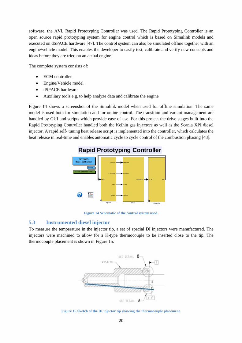
Figure 14 shows a screenshot of the Simulink model when used for offline simulation. The same model is used both for simulation and for online control. The transition and variant management are handled by GUI and scripts which provide ease of use. For this project the drive stages built into the Rapid Prototyping Controller handled both the Keihin gas injectors as well as the Scania XPI diesel injector. A rapid self- tuning heat release script is implemented into the controller, which calculates the heat release in real-time and enables automatic cycle to cycle control of the combustion phasing [48].
Figure 14 Schematic of the control system used.
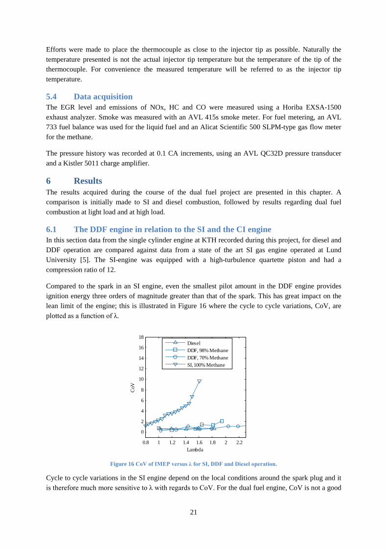
5.3 Instrumented diesel injector To measure the temperature in the injector tip, a set of special DI injectors were manufactured. The injectors were machined to allow for a K-type thermocouple to be inserted close to the tip. The thermocouple placement is shown in Figure 15.
Figure 15 Sketch of the DI injector tip showing the thermocouple placement.
Rapid Prototyping Controller
Check for broken links
Scope
SETTINGS:Base_Calibration
ECM SIG
Outputs
SNS
Sensors
CombTrig
10ms
2p5ms
Inputs
Sensors
LowRes
10ms
2p5ms
Actuators
ECM
21
Efforts were made to place the thermocouple as close to the injector tip as possible. Naturally the temperature presented is not the actual injector tip temperature but the temperature of the tip of the thermocouple. For convenience the measured temperature will be referred to as the injector tip temperature.
5.4 Data acquisition The EGR level and emissions of NOx, HC and CO were measured using a Horiba EXSA-1500 exhaust analyzer. Smoke was measured with an AVL 415s smoke meter. For fuel metering, an AVL 733 fuel balance was used for the liquid fuel and an Alicat Scientific 500 SLPM-type gas flow meter for the methane.
The pressure history was recorded at 0.1 CA increments, using an AVL QC32D pressure transducer and a Kistler 5011 charge amplifier.
6 Results The results acquired during the course of the dual fuel project are presented in this chapter. A comparison is initially made to SI and diesel combustion, followed by results regarding dual fuel combustion at light load and at high load.
6.1 The DDF engine in relation to the SI and the CI engine In this section data from the single cylinder engine at KTH recorded during this project, for diesel and DDF operation are compared against data from a state of the art SI gas engine operated at Lund University [5]. The SI-engine was equipped with a high-turbulence quartette piston and had a compression ratio of 12.
Compared to the spark in an SI engine, even the smallest pilot amount in the DDF engine provides ignition energy three orders of magnitude greater than that of the spark. This has great impact on the lean limit of the engine; this is illustrated in Figure 16 where the cycle to cycle variations, CoV, are plotted as a function of λ.
Figure 16 CoV of IMEP versus λ for SI, DDF and Diesel operation.
Cycle to cycle variations in the SI engine depend on the local conditions around the spark plug and it is therefore much more sensitive to λ with regards to CoV. For the dual fuel engine, CoV is not a good
0.8 1 1.2 1.4 1.6 1.8 2 2.2
0
2
4
6
8
10
12
14
16
18
Lambda
CoV
DieselDDF, 98% MethaneDDF, 70% MethaneSI, 100% Methane
22
indication of combustion quality since emissions of HC and CO will reach intolerable levels before combustion stability becomes an issue.
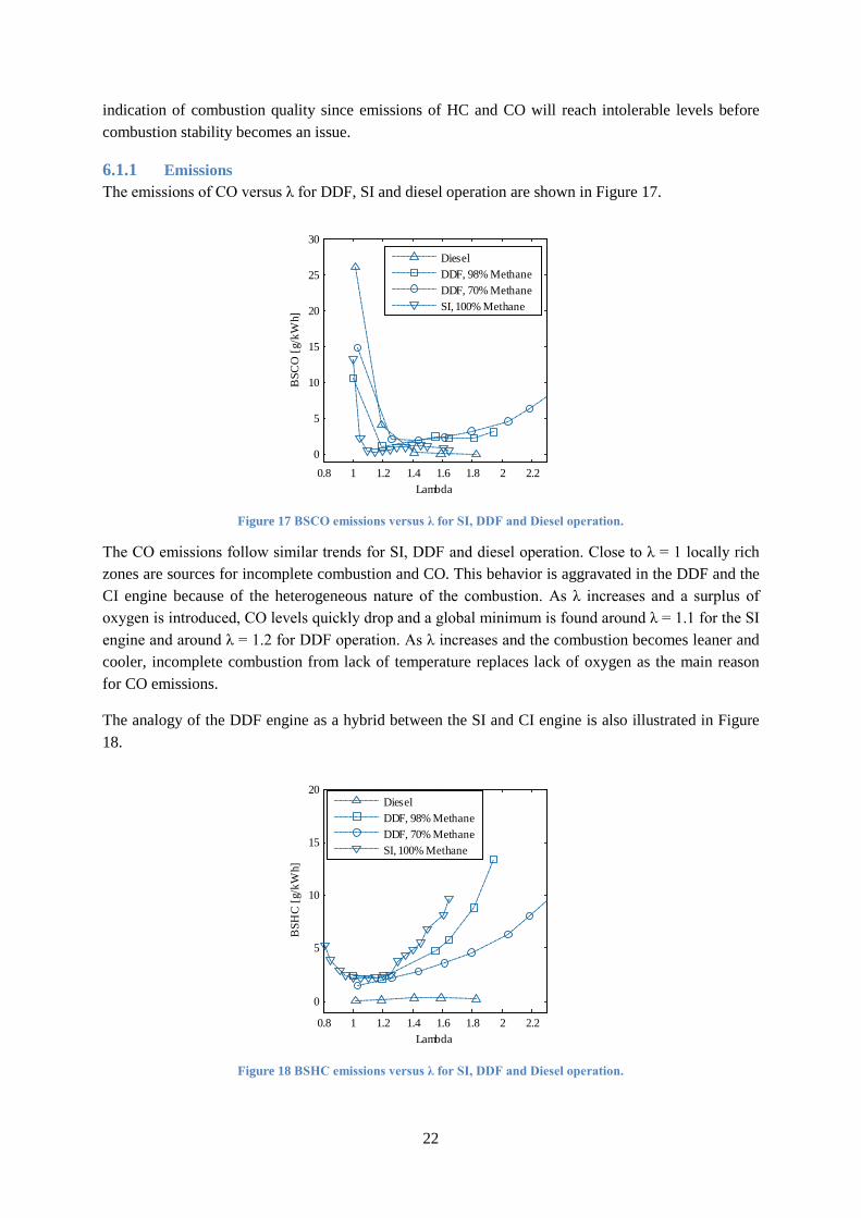
6.1.1 Emissions The emissions of CO versus λ for DDF, SI and diesel operation are shown in Figure 17.
Figure 17 BSCO emissions versus λ for SI, DDF and Diesel operation.
The CO emissions follow similar trends for SI, DDF and diesel operation. Close to λ = 1 locally rich zones are sources for incomplete combustion and CO. This behavior is aggravated in the DDF and the CI engine because of the heterogeneous nature of the combustion. As λ increases and a surplus of oxygen is introduced, CO levels quickly drop and a global minimum is found around λ = 1.1 for the SI engine and around λ = 1.2 for DDF operation. As λ increases and the combustion becomes leaner and cooler, incomplete combustion from lack of temperature replaces lack of oxygen as the main reason for CO emissions.
The analogy of the DDF engine as a hybrid between the SI and CI engine is also illustrated in Figure 18.
Figure 18 BSHC emissions versus λ for SI, DDF and Diesel operation.
0.8 1 1.2 1.4 1.6 1.8 2 2.20
5
10
15
20
25
30
Lambda
BSC
O [g
/kW
h]
DieselDDF, 98% MethaneDDF, 70% MethaneSI, 100% Methane
0.8 1 1.2 1.4 1.6 1.8 2 2.2
0
5
10
15
20
Lambda
BSH
C [g
/kW
h]
DieselDDF, 98% MethaneDDF, 70% MethaneSI, 100% Methane
23
For the SI engine, the HC emissions increase monotonously with λ for λ >1.2. The same trend is observed for the DDF engine but the behavior is substantially improved. If 10 g/kWh is assumed to be an acceptable emission limit for lean operation, at 98% diesel substitution the maximum allowable λ is extended by 0.2 compared to the SI engine. At substitution rates of 98%, the main heat release comes from flame propagation through the methane-air mixture. The flame propagation is aided by the high temperatures in the DDF engine resulting from the high compression ratio. The flame propagation also benefits from the increased combustion speed from the multiple ignition sources provided by the diesel pilot which allows combustion to finish earlier in the expansion stroke. For 70% diesel substitution, by the same definition, maximum allowable λ is extended by 0.7. In this case, the amount of diesel is sufficient for a complex mix of flame propagation and diffusion combustion to take place. The improvement to the lean limit in the DDF engine compared to the SI engine has large implications for brake efficiency at light load since throttling and the resulting pumping losses can be reduced. For diesel operation BSHC emissions remain essentially flat. HC emissions from dual fuel engines are discussed further in Chapter 4.
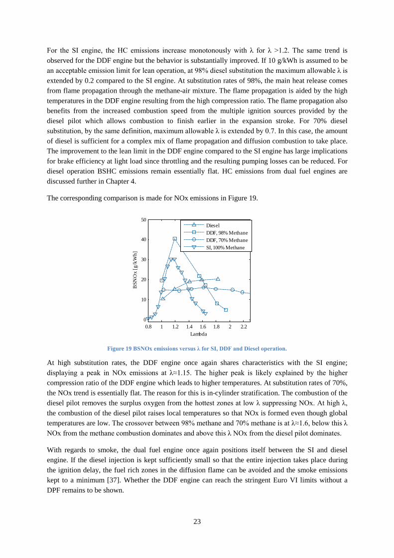
The corresponding comparison is made for NOx emissions in Figure 19.
Figure 19 BSNOx emissions versus λ for SI, DDF and Diesel operation.
At high substitution rates, the DDF engine once again shares characteristics with the SI engine; displaying a peak in NOx emissions at λ≈1.15. The higher peak is likely explained by the higher compression ratio of the DDF engine which leads to higher temperatures. At substitution rates of 70%, the NOx trend is essentially flat. The reason for this is in-cylinder stratification. The combustion of the diesel pilot removes the surplus oxygen from the hottest zones at low λ suppressing NOx. At high λ, the combustion of the diesel pilot raises local temperatures so that NOx is formed even though global temperatures are low. The crossover between 98% methane and 70% methane is at λ≈1.6, below this λ NOx from the methane combustion dominates and above this λ NOx from the diesel pilot dominates.
With regards to smoke, the dual fuel engine once again positions itself between the SI and diesel engine. If the diesel injection is kept sufficiently small so that the entire injection takes place during the ignition delay, the fuel rich zones in the diffusion flame can be avoided and the smoke emissions kept to a minimum [37]. Whether the DDF engine can reach the stringent Euro VI limits without a DPF remains to be shown.
0.8 1 1.2 1.4 1.6 1.8 2 2.20
10
20
30
40
50
Lambda
BSN
Ox
[g/k
Wh]
DieselDDF, 98% MethaneDDF, 70% MethaneSI, 100% Methane
24
6.1.2 Efficiency If high diesel substitution rates are to be reached, the efficiency of DDF combustion will be dependent on good flame propagation. Flame propagation is more sensitive to λ and EGR than diffusion combustion and for this reason throttling is needed at light load, penalizing the efficiency of the engine in comparison to unthrottled CI operation. Compared to the SI engine, it has been showed that the DDF engine can operate substantially leaner, thus providing an efficiency benefit over the SI engine. At medium and high load, the high compression ratio and the high flame speed in the DDF engine resulting from the large ignition source will allow the efficiency of the DDF engine to surpass both diesel and SI operation. Over an entire driving cycle, the DDF engine will most likely position itself between the SI and the CI engine with regards to efficiency.
6.1.3 Summary of the DDF engine in relation to the SI and CI engine The main message in this chapter is that the DDF engine shares characteristics with both the diesel engine and the SI engine, but it is neither. Since diesel engine hardware is used, DDF operation is usually compared to diesel operation with regards to efficiency. While such a comparison might provide an interesting point of reference; it is not especially relevant. For instance; while developing an SI engine it would not be productive to try to match the efficiency of the corresponding diesel engine. Such a practice would most likely lead to no SI engines reaching the market. Instead, it is generally accepted that the SI engine has its place on the market, alongside the diesel engine, in spite of its lower brake efficiency. Based on the environmental concerns and supply constraints discussed in the introduction, the DDF engine likely has a niche alongside the diesel engine for HD applications and therefore does not necessarily have to compete directly in terms of brake efficiency.
6.2 Dual fuel at light load In this section, a summary description of the challenges of dual fuel operation at light load is given. There is also a sub-chapter describing how the unique degree of freedom available in the DDF engine can be utilized to realize unconventional combustion modes which address these problems.
The challenges of dual fuel operation at light load consist largely of managing the conflicting needs to keep HC emissions within the limits of the after treatment system with the desire to operate at high diesel substitution rates and to keep throttling at a minimum to improve brake efficiency.
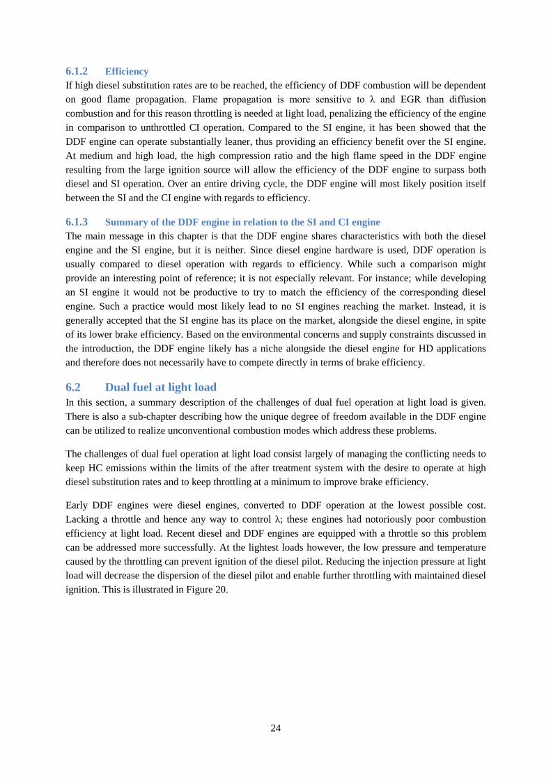
Early DDF engines were diesel engines, converted to DDF operation at the lowest possible cost. Lacking a throttle and hence any way to control λ; these engines had notoriously poor combustion efficiency at light load. Recent diesel and DDF engines are equipped with a throttle so this problem can be addressed more successfully. At the lightest loads however, the low pressure and temperature caused by the throttling can prevent ignition of the diesel pilot. Reducing the injection pressure at light load will decrease the dispersion of the diesel pilot and enable further throttling with maintained diesel ignition. This is illustrated in Figure 20.
25
Figure 20 Lowest possible loads attainable in DDF operation versus common rail pressure for three different diesel substitution rates.
The data shown in Figure 20 is generated by setting a limit for HC emissions, since HC emissions increase with λ this effectively imposes a limit on intake manifold pressure. A larger diesel pilot extends the lean limit, as seen in Figure 18, which means less throttling is needed for a given load. At loads below the ones shown and at idle, the remaining option is to resort to diesel operation.
6.2.1 Unconventional combustion modes, HCCI/RCCI and PPCI Unconventional combustion modes such as HCCI and PPC have received a lot of attention during the past decade. From a combustion point of view the results are encouraging but the enthusiasm has, with a few notable exceptions, not resulted in any production engines. The main obstacles to realizing these combustion modes can be summarized into two categories; the difficulty to obtain information about combustion phasing and the difficulty to control it once information is made available.
Information about combustion phasing can be gained by several methods; ion current measurements, fast torque measurements, engine speed variations and cylinder pressure transducers to name a few. Currently only cylinder pressure measurements are demonstrated to give information of sufficient quality for combustion phasing close to TDC. However, cylinder pressure transducers have not yet made their way into heavy duty engines. At the time of writing, this problem remains to be solved.
Since combustion phasing and combustion speed are governed to a large extent by chemical kinetics, the methods available for control differ from the SI and the CI engine. Several control methods have been proposed; fast control of inlet temperature, fast compression ratio changes, fast EGR adjustments to name a few. In addition to these methods, it is also possible to mix two fuels and in this way create a compound fuel with a cetane number tailored for the current operating conditions, recently referred to as fuel reactivity controlled compression ignition, RCCI. This was suggested for DME and methane in [49]. In the dual fuel engine, a high cetane and a low cetane fuel is readily available on board the vehicle making this approach very suitable.
To approach the subject of unconventional combustion modes a well-known phenomenon for DDF operation is shown in Figure 21. The graph shows rate of heat release versus crank angle for different injection timings of the diesel pilot.
5001000150020002
2.5
3
3.5
4
4.5
5
CommonRail Pressure [bar]
BM
EP [b
ar]
4 mg, 95% Methane8 mg, 85% Methane12 mg, 75% Methane
26
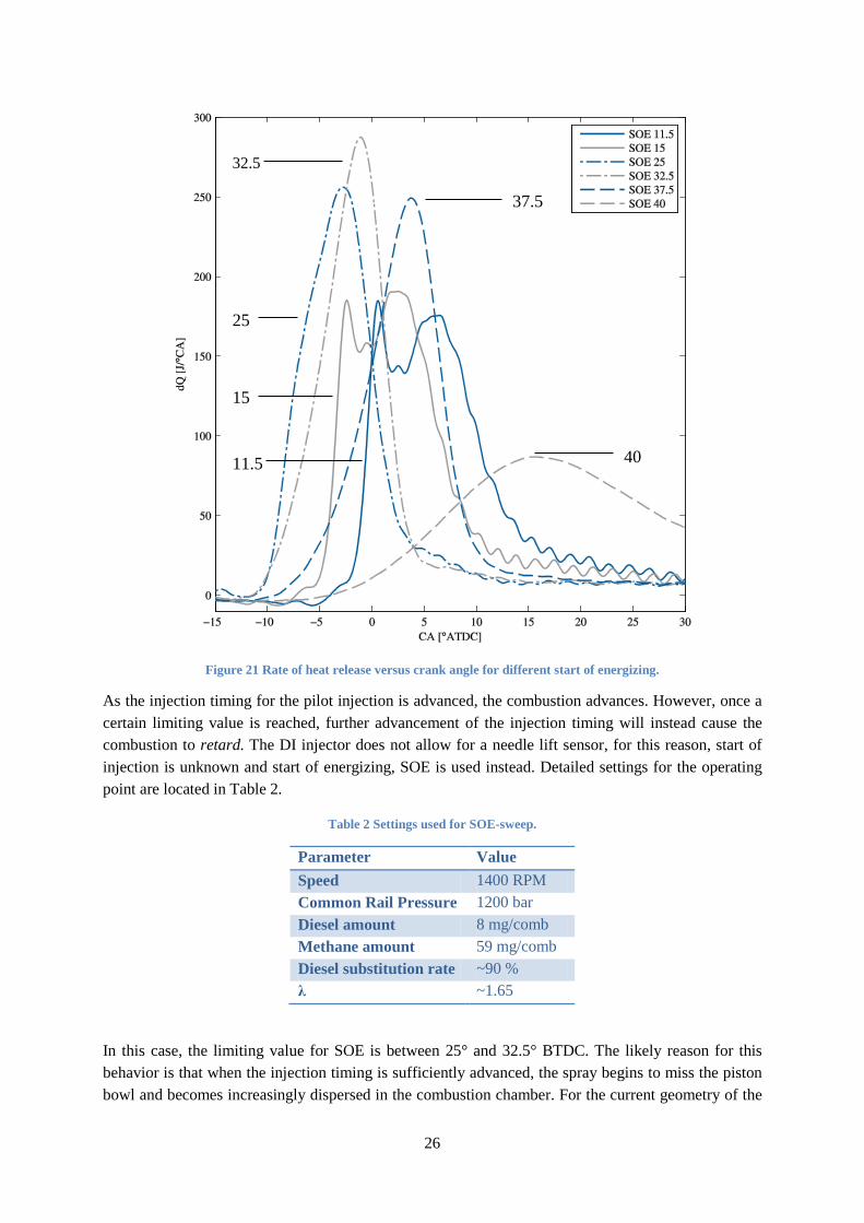
Figure 21 Rate of heat release versus crank angle for different start of energizing.
As the injection timing for the pilot injection is advanced, the combustion advances. However, once a certain limiting value is reached, further advancement of the injection timing will instead cause the combustion to retard. The DI injector does not allow for a needle lift sensor, for this reason, start of injection is unknown and start of energizing, SOE is used instead. Detailed settings for the operating point are located in Table 2.
Table 2 Settings used for SOE-sweep.
Parameter Value Speed 1400 RPM Common Rail Pressure 1200 bar Diesel amount 8 mg/comb Methane amount 59 mg/comb Diesel substitution rate ~90 % λ ~1.65
In this case, the limiting value for SOE is between 25° and 32.5° BTDC. The likely reason for this behavior is that when the injection timing is sufficiently advanced, the spray begins to miss the piston bowl and becomes increasingly dispersed in the combustion chamber. For the current geometry of the
25
32.5
37.5
11.5
15
40
27
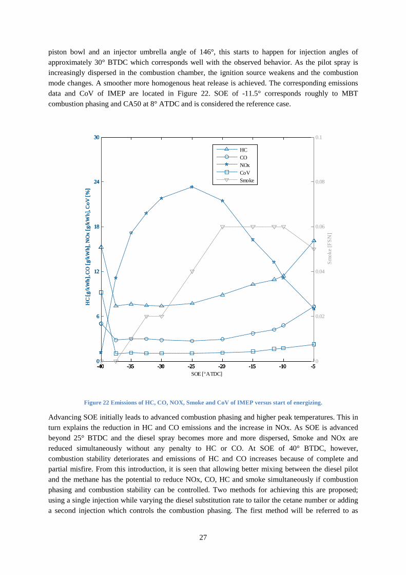
piston bowl and an injector umbrella angle of 146°, this starts to happen for injection angles of approximately 30° BTDC which corresponds well with the observed behavior. As the pilot spray is increasingly dispersed in the combustion chamber, the ignition source weakens and the combustion mode changes. A smoother more homogenous heat release is achieved. The corresponding emissions data and CoV of IMEP are located in Figure 22. SOE of -11.5° corresponds roughly to MBT combustion phasing and CA50 at 8° ATDC and is considered the reference case.
Figure 22 Emissions of HC, CO, NOX, Smoke and CoV of IMEP versus start of energizing.
Advancing SOE initially leads to advanced combustion phasing and higher peak temperatures. This in turn explains the reduction in HC and CO emissions and the increase in NOx. As SOE is advanced beyond 25° BTDC and the diesel spray becomes more and more dispersed, Smoke and NOx are reduced simultaneously without any penalty to HC or CO. At SOE of 40° BTDC, however, combustion stability deteriorates and emissions of HC and CO increases because of complete and partial misfire. From this introduction, it is seen that allowing better mixing between the diesel pilot and the methane has the potential to reduce NOx, CO, HC and smoke simultaneously if combustion phasing and combustion stability can be controlled. Two methods for achieving this are proposed; using a single injection while varying the diesel substitution rate to tailor the cetane number or adding a second injection which controls the combustion phasing. The first method will be referred to as
-40 -35 -30 -25 -20 -15 -10 -50
6
12
18
24
30
HC
[g/k
Wh]
, CO
[g/k
Wh]
, NO
x [g
/kW
h], C
oV [%
]
HCSmokeCONOxCoV
-40 -35 -30 -25 -20 -15 -10 -50
6
12
18
24
30
HC
[g/k
Wh]
, CO
[g/k
Wh]
, NO
x [g
/kW
h], C
oV [%
]
HCCONOxCoVSmoke
-40 -35 -30 -25 -20 -15 -10 -50
6
12
18
24
30
HC
[g/k
Wh]
, CO
[g/k
Wh]
, NO
x [g
/kW
h], C
oV [%
]
-40 -35 -30 -25 -20 -15 -10 -50
0.02
0.04
0.06
0.08
0.1
SOE [°ATDC]
Smok
e [F
SN]
HCCONOxCoVSmoke
28
Homogenous Charge Compression Ignition, HCCI, even though the charge is not expected to be completely homogenous and the second one as Partially Premixed Compression Ignition, PPCI.
6.2.1.1 HCCI/RCCI As the injection timing in Figure 22 is advanced to 40°BTDC near zero emissions of NOx and smoke is achieved but combustion stability, HC and CO emissions deteriorate. This can be addressed by increasing the size of the diesel injection and advancing it even further to allow longer time for mixing. This results in HCCI combustion with low HC and CO emissions, satisfactory combustion stability and near zero emissions of NOx and smoke.
In HCCI combustion, the combustion timing and speed is governed entirely by chemical kinetics. Combustion is therefore very sensitive to the small changes in local temperature which occur stochastically in combustion engines. There is also a strong possibility of positive feedback; if combustion occurs early one cycle, more heat is transferred to the combustion chamber walls, thus heating valves and piston crown. Because of this; the gases during the next cycle are exposed to higher temperatures and the probability increases that combustion will advance even further. This situation can quickly escalate and within fractions of a second lead to intolerable peak firing pressures and rates of pressure rise. This behavior is aggravated as the load increases and it is generally accepted that closed loop control of combustion phasing is needed at higher loads. Whether HCCI combustion can be controlled at light load without closed loop control is a possibility which remains to be proven.
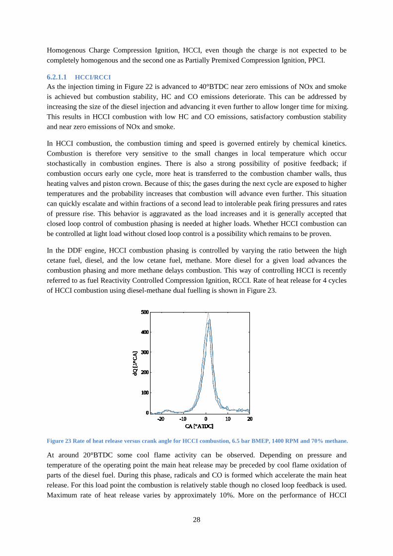
In the DDF engine, HCCI combustion phasing is controlled by varying the ratio between the high cetane fuel, diesel, and the low cetane fuel, methane. More diesel for a given load advances the combustion phasing and more methane delays combustion. This way of controlling HCCI is recently referred to as fuel Reactivity Controlled Compression Ignition, RCCI. Rate of heat release for 4 cycles of HCCI combustion using diesel-methane dual fuelling is shown in Figure 23.
Figure 23 Rate of heat release versus crank angle for HCCI combustion, 6.5 bar BMEP, 1400 RPM and 70% methane.
At around 20°BTDC some cool flame activity can be observed. Depending on pressure and temperature of the operating point the main heat release may be preceded by cool flame oxidation of parts of the diesel fuel. During this phase, radicals and CO is formed which accelerate the main heat release. For this load point the combustion is relatively stable though no closed loop feedback is used. Maximum rate of heat release varies by approximately 10%. More on the performance of HCCI
-20 -10 0 10 200
100
200
300
400
500
CA [°ATDC]
dQ [J
/ °CA
]
HCCI
-20 -10 0 10 200
100
200
300
400
500
CA [°ATDC]
dQ [J
/ °CA
]
HCCI
-20 -10 0 10 200
100
200
300
400
500
CA [°ATDC]
dQ [J
/ °CA
]
HCCI
-20 -10 0 10 200
100
200
300
400
500
CA [°ATDC]
dQ [J
/ °CA
]
HCCI
-20 -10 0 10 200
100
200
300
400
500
CA [°ATDC]
dQ [J
/ °CA
]
HCCI
-20 -10 0 10 200
100
200
300
400
500
CA [°ATDC]
dQ [J
/ °CA
]
HCCI
-20 -10 0 10 200
100
200
300
400
500
CA [°ATDC]
dQ [J
/ °CA
]
HCCI
-20 -10 0 10 200
100
200
300
400
500
CA [°ATDC]
dQ [J
/ °CA
]
HCCI
-20 -10 0 10 200
100
200
300
400
500
CA [°ATDC]
dQ [J
/ °CA
]
-20 -10 0 10 200
100
200
300
400
500
CA [°ATDC]
dQ [J
/ °CA
]
29
combustion in relation to diesel, DDF and PPCI is found in the section named HCCI/RCCI and PPCI at highly diluted conditions.
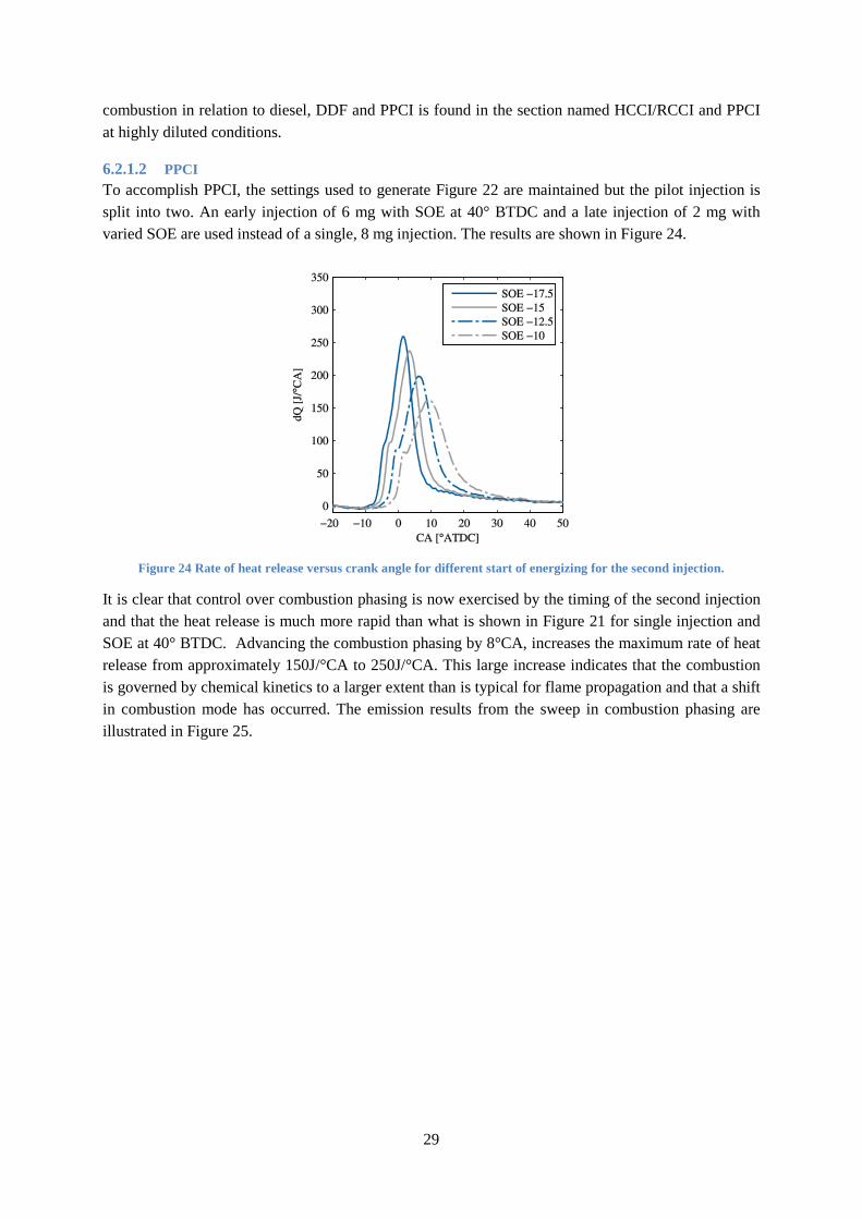
6.2.1.2 PPCI To accomplish PPCI, the settings used to generate Figure 22 are maintained but the pilot injection is split into two. An early injection of 6 mg with SOE at 40° BTDC and a late injection of 2 mg with varied SOE are used instead of a single, 8 mg injection. The results are shown in Figure 24.
Figure 24 Rate of heat release versus crank angle for different start of energizing for the second injection.
It is clear that control over combustion phasing is now exercised by the timing of the second injection and that the heat release is much more rapid than what is shown in Figure 21 for single injection and SOE at 40° BTDC. Advancing the combustion phasing by 8°CA, increases the maximum rate of heat release from approximately 150J/°CA to 250J/°CA. This large increase indicates that the combustion is governed by chemical kinetics to a larger extent than is typical for flame propagation and that a shift in combustion mode has occurred. The emission results from the sweep in combustion phasing are illustrated in Figure 25.
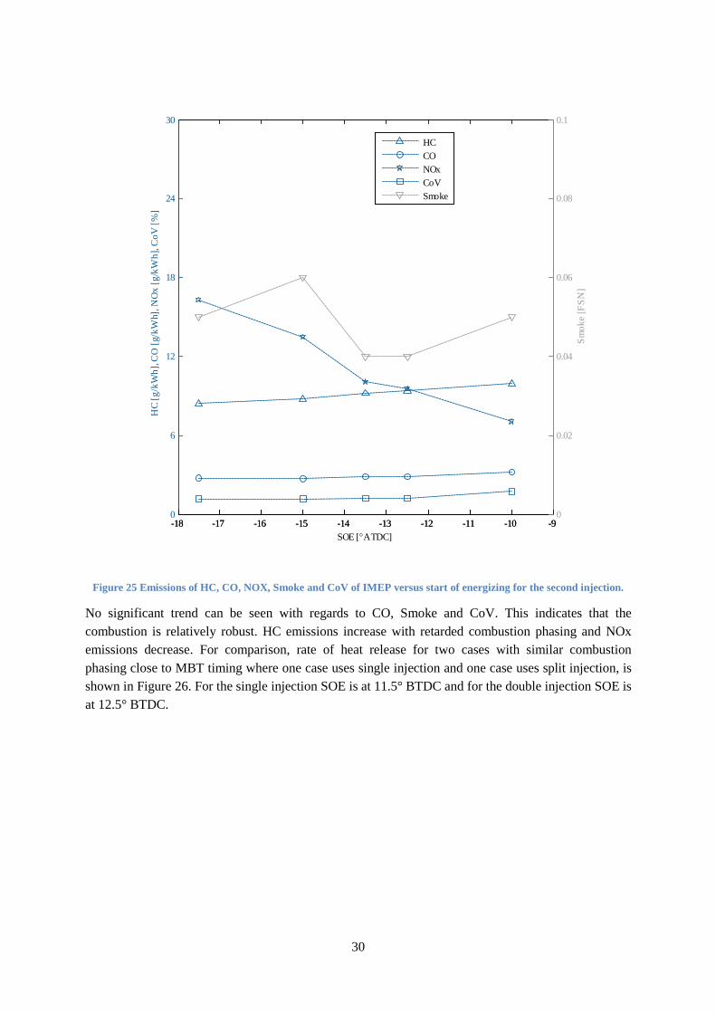
30
Figure 25 Emissions of HC, CO, NOX, Smoke and CoV of IMEP versus start of energizing for the second injection.
No significant trend can be seen with regards to CO, Smoke and CoV. This indicates that the combustion is relatively robust. HC emissions increase with retarded combustion phasing and NOx emissions decrease. For comparison, rate of heat release for two cases with similar combustion phasing close to MBT timing where one case uses single injection and one case uses split injection, is shown in Figure 26. For the single injection SOE is at 11.5° BTDC and for the double injection SOE is at 12.5° BTDC.
-18 -17 -16 -15 -14 -13 -12 -11 -10 -90
6
12
18
24
30
HC
[g/k
Wh]
, CO
[g/k
Wh]
, NO
x [g
/kW
h], C
oV [%
]
-18 -17 -16 -15 -14 -13 -12 -11 -10 -90
0.02
0.04
0.06
0.08
0.1
SOE [°ATDC]
Smok
e [F
SN]
HCCONOxCoVSmoke
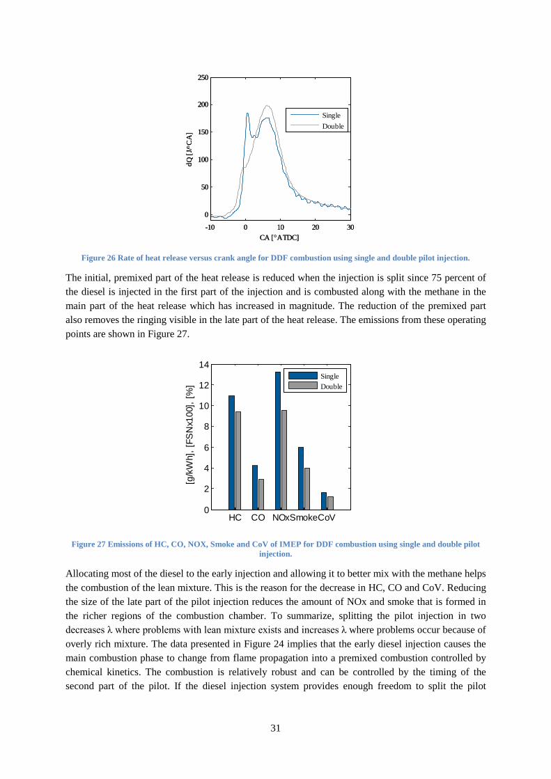
31
Figure 26 Rate of heat release versus crank angle for DDF combustion using single and double pilot injection.
The initial, premixed part of the heat release is reduced when the injection is split since 75 percent of the diesel is injected in the first part of the injection and is combusted along with the methane in the main part of the heat release which has increased in magnitude. The reduction of the premixed part also removes the ringing visible in the late part of the heat release. The emissions from these operating points are shown in Figure 27.
Figure 27 Emissions of HC, CO, NOX, Smoke and CoV of IMEP for DDF combustion using single and double pilot injection.
Allocating most of the diesel to the early injection and allowing it to better mix with the methane helps the combustion of the lean mixture. This is the reason for the decrease in HC, CO and CoV. Reducing the size of the late part of the pilot injection reduces the amount of NOx and smoke that is formed in the richer regions of the combustion chamber. To summarize, splitting the pilot injection in two decreases λ where problems with lean mixture exists and increases λ where problems occur because of overly rich mixture. The data presented in Figure 24 implies that the early diesel injection causes the main combustion phase to change from flame propagation into a premixed combustion controlled by chemical kinetics. The combustion is relatively robust and can be controlled by the timing of the second part of the pilot. If the diesel injection system provides enough freedom to split the pilot
-10 0 10 20 30
0
50
100
150
200
250
CA [°ATDC]
dQ [J
/ °CA
]
-10 0 10 20 30
0
50
100
150
200
250
CA [°ATDC]
dQ [J
/ °CA
]
SingleDouble
HC CO NOxSmokeCoV0
2
4
6
8
10
12
14
[g/k
Wh]
, [FS
Nx1
00],
[%]
SingleDouble
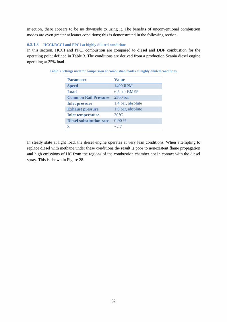
32
injection, there appears to be no downside to using it. The benefits of unconventional combustion modes are even greater at leaner conditions; this is demonstrated in the following section.
6.2.1.3 HCCI/RCCI and PPCI at highly diluted conditions In this section, HCCI and PPCI combustion are compared to diesel and DDF combustion for the operating point defined in Table 3. The conditions are derived from a production Scania diesel engine operating at 25% load.
Table 3 Settings used for comparison of combustion modes at highly diluted conditions.
Parameter Value Speed 1400 RPM Load 6.5 bar BMEP Common Rail Pressure 2500 bar Inlet pressure 1.4 bar, absolute Exhaust pressure 1.6 bar, absolute Inlet temperature 30°C Diesel substitution rate 0-90 % λ ~2.7
In steady state at light load, the diesel engine operates at very lean conditions. When attempting to replace diesel with methane under these conditions the result is poor to nonexistent flame propagation and high emissions of HC from the regions of the combustion chamber not in contact with the diesel spray. This is shown in Figure 28.
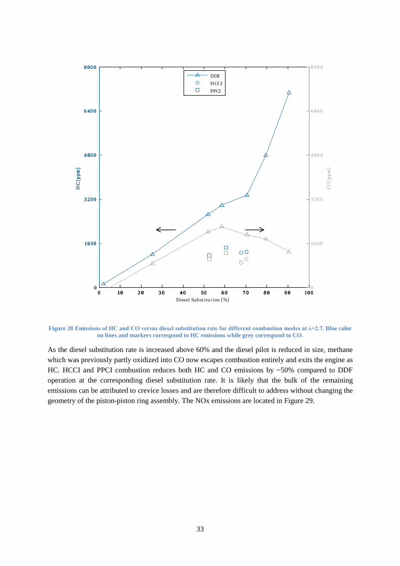
33
Figure 28 Emissions of HC and CO versus diesel substitution rate for different combustion modes at λ=2.7. Blue color on lines and markers correspond to HC emissions while grey correspond to CO.
As the diesel substitution rate is increased above 60% and the diesel pilot is reduced in size, methane which was previously partly oxidized into CO now escapes combustion entirely and exits the engine as HC. HCCI and PPCI combustion reduces both HC and CO emissions by ~50% compared to DDF operation at the corresponding diesel substitution rate. It is likely that the bulk of the remaining emissions can be attributed to crevice losses and are therefore difficult to address without changing the geometry of the piston-piston ring assembly. The NOx emissions are located in Figure 29.
0 1 0 20 30 40 50 60 7 0 80 90 1 000
1 600
3200
4800
6400
8000
HC
[ppm
]
DDFHCCIPPCI
0 1 0 20 30 40 50 60 7 0 80 90 1 000
1 600
3200
4800
6400
8000
HC
[ppm
]
DDFHCCIPPCI
0 1 0 20 30 40 50 60 7 0 80 90 1 000
1 600
3200
4800
6400
8000
HC
[ppm
]
0 1 0 20 30 40 50 60 7 0 80 90 1 000
1 600
3200
4800
6400
8000
Diesel Substitution [%]
CO
[pp
m]
DDFHCCIPPCI
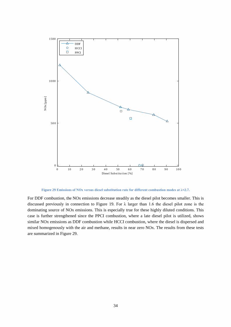
34
Figure 29 Emissions of NOx versus diesel substitution rate for different combustion modes at λ≈2.7.
For DDF combustion, the NOx emissions decrease steadily as the diesel pilot becomes smaller. This is discussed previously in connection to Figure 19. For λ larger than 1.6 the diesel pilot zone is the dominating source of NOx emissions. This is especially true for these highly diluted conditions. This case is further strengthened since the PPCI combustion, where a late diesel pilot is utilized, shows similar NOx emissions as DDF combustion while HCCI combustion, where the diesel is dispersed and mixed homogenously with the air and methane, results in near zero NOx. The results from these tests are summarized in Figure 29.
0 1 0 20 30 40 50 60 7 0 80 90 1 000
500
1 000
1 500
Diesel Substitution [%]
NO
x [p
pm]
DDFHCCIPPCI
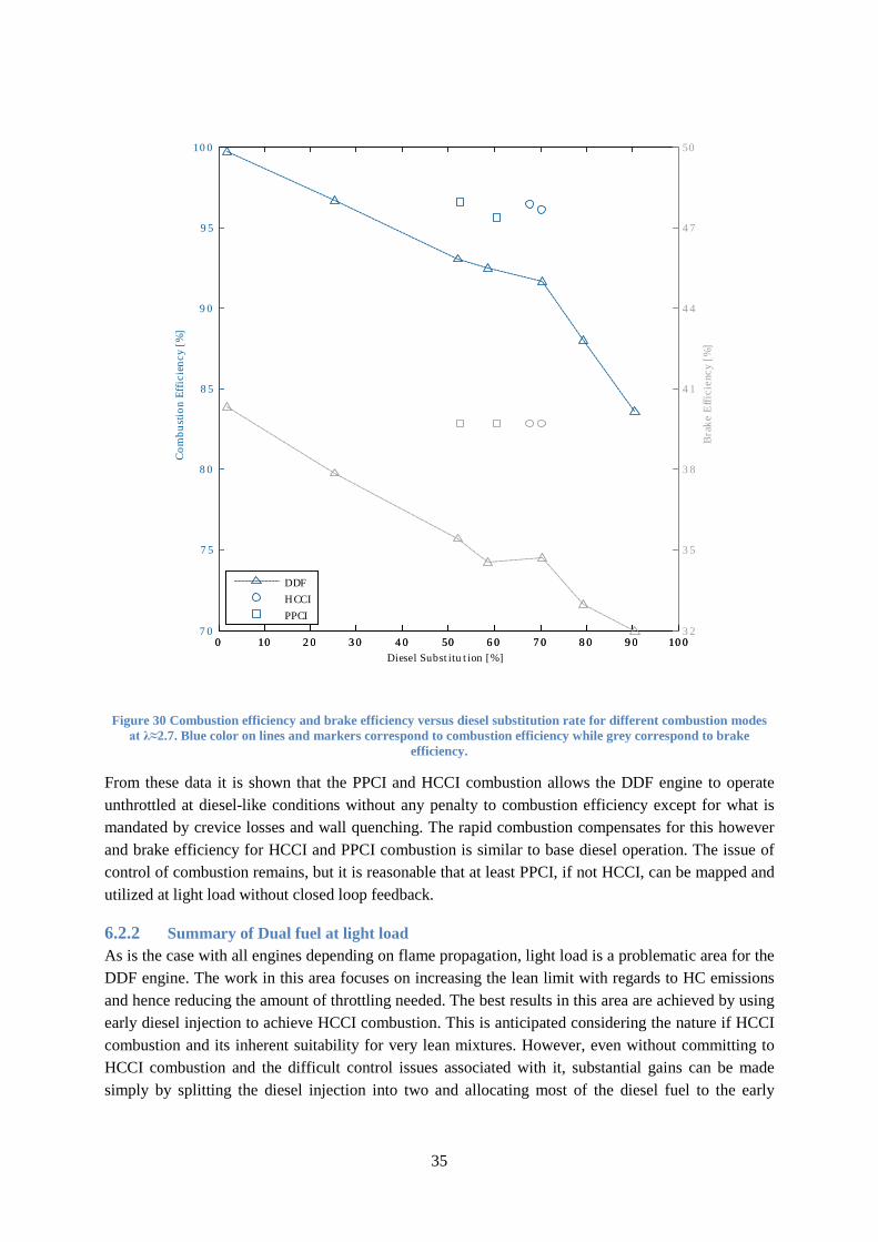
35
Figure 30 Combustion efficiency and brake efficiency versus diesel substitution rate for different combustion modes at λ≈2.7. Blue color on lines and markers correspond to combustion efficiency while grey correspond to brake
efficiency.
From these data it is shown that the PPCI and HCCI combustion allows the DDF engine to operate unthrottled at diesel-like conditions without any penalty to combustion efficiency except for what is mandated by crevice losses and wall quenching. The rapid combustion compensates for this however and brake efficiency for HCCI and PPCI combustion is similar to base diesel operation. The issue of control of combustion remains, but it is reasonable that at least PPCI, if not HCCI, can be mapped and utilized at light load without closed loop feedback.
6.2.2 Summary of Dual fuel at light load As is the case with all engines depending on flame propagation, light load is a problematic area for the DDF engine. The work in this area focuses on increasing the lean limit with regards to HC emissions and hence reducing the amount of throttling needed. The best results in this area are achieved by using early diesel injection to achieve HCCI combustion. This is anticipated considering the nature if HCCI combustion and its inherent suitability for very lean mixtures. However, even without committing to HCCI combustion and the difficult control issues associated with it, substantial gains can be made simply by splitting the diesel injection into two and allocating most of the diesel fuel to the early
0 1 0 20 30 40 50 60 7 0 80 90 1 007 0
7 5
80
85
90
95
1 00
Com
bust
ion
Effi
cien
cy [
%]
0 1 0 20 30 40 50 60 7 0 80 90 1 0032
35
38
41
44
47
50
Diesel Substitution [%]
Bra
ke E
ffici
ency
[%
]
DDFHCCIPPCI
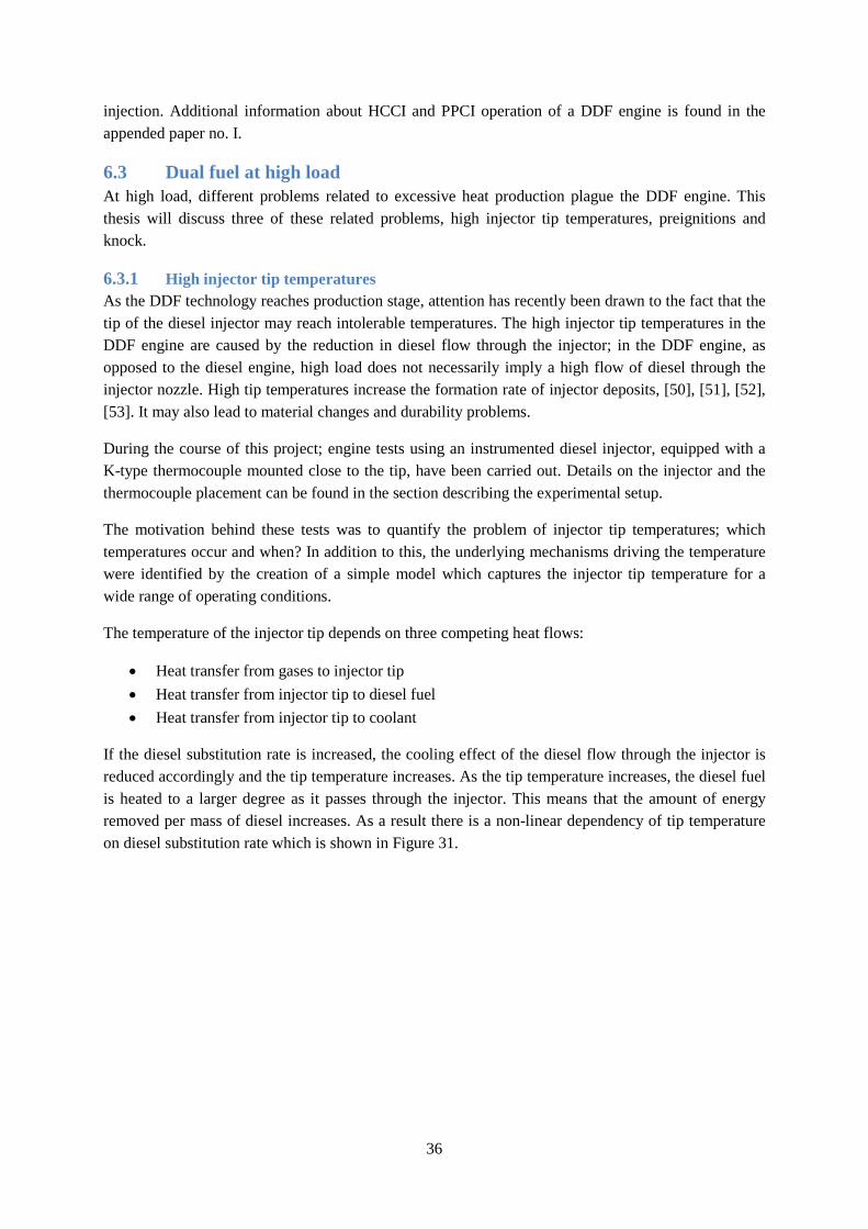
36
injection. Additional information about HCCI and PPCI operation of a DDF engine is found in the appended paper no. I.
6.3 Dual fuel at high load At high load, different problems related to excessive heat production plague the DDF engine. This thesis will discuss three of these related problems, high injector tip temperatures, preignitions and knock.
6.3.1 High injector tip temperatures As the DDF technology reaches production stage, attention has recently been drawn to the fact that the tip of the diesel injector may reach intolerable temperatures. The high injector tip temperatures in the DDF engine are caused by the reduction in diesel flow through the injector; in the DDF engine, as opposed to the diesel engine, high load does not necessarily imply a high flow of diesel through the injector nozzle. High tip temperatures increase the formation rate of injector deposits, [50], [51], [52], [53]. It may also lead to material changes and durability problems.
During the course of this project; engine tests using an instrumented diesel injector, equipped with a K-type thermocouple mounted close to the tip, have been carried out. Details on the injector and the thermocouple placement can be found in the section describing the experimental setup.
The motivation behind these tests was to quantify the problem of injector tip temperatures; which temperatures occur and when? In addition to this, the underlying mechanisms driving the temperature were identified by the creation of a simple model which captures the injector tip temperature for a wide range of operating conditions.
The temperature of the injector tip depends on three competing heat flows:
• Heat transfer from gases to injector tip • Heat transfer from injector tip to diesel fuel • Heat transfer from injector tip to coolant
If the diesel substitution rate is increased, the cooling effect of the diesel flow through the injector is reduced accordingly and the tip temperature increases. As the tip temperature increases, the diesel fuel is heated to a larger degree as it passes through the injector. This means that the amount of energy removed per mass of diesel increases. As a result there is a non-linear dependency of tip temperature on diesel substitution rate which is shown in Figure 31.
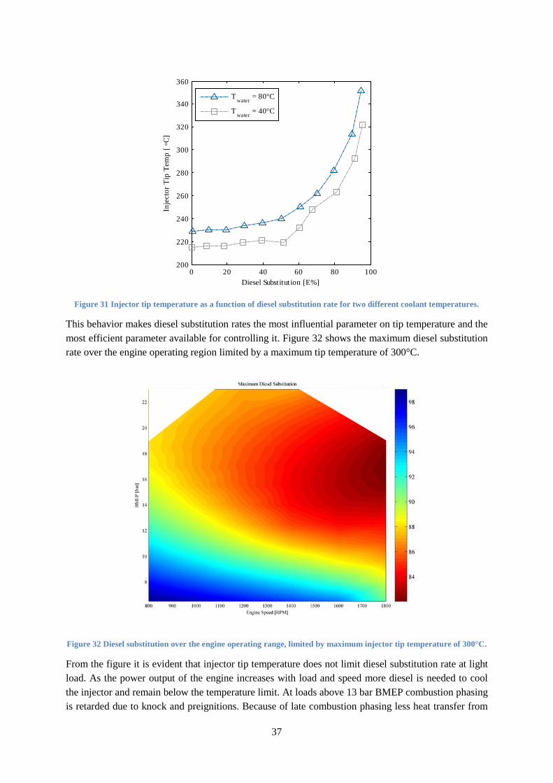
37
Figure 31 Injector tip temperature as a function of diesel substitution rate for two different coolant temperatures.
This behavior makes diesel substitution rates the most influential parameter on tip temperature and the most efficient parameter available for controlling it. Figure 32 shows the maximum diesel substitution rate over the engine operating region limited by a maximum tip temperature of 300°C.
Figure 32 Diesel substitution over the engine operating range, limited by maximum injector tip temperature of 300°C.
From the figure it is evident that injector tip temperature does not limit diesel substitution rate at light load. As the power output of the engine increases with load and speed more diesel is needed to cool the injector and remain below the temperature limit. At loads above 13 bar BMEP combustion phasing is retarded due to knock and preignitions. Because of late combustion phasing less heat transfer from
0 20 40 60 80 100200
220
240
260
280
300
320
340
360
Diesel Substitution [E%]
Inje
ctor
Tip
Tem
p [ °
C]
T water = 80°C
T water = 40°C
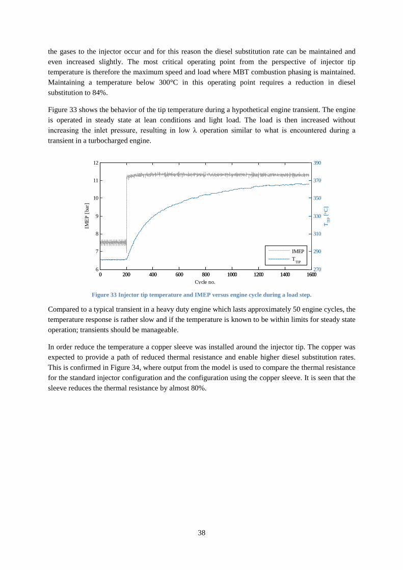
38
the gases to the injector occur and for this reason the diesel substitution rate can be maintained and even increased slightly. The most critical operating point from the perspective of injector tip temperature is therefore the maximum speed and load where MBT combustion phasing is maintained. Maintaining a temperature below 300°C in this operating point requires a reduction in diesel substitution to 84%.
Figure 33 shows the behavior of the tip temperature during a hypothetical engine transient. The engine is operated in steady state at lean conditions and light load. The load is then increased without increasing the inlet pressure, resulting in low λ operation similar to what is encountered during a transient in a turbocharged engine.
Figure 33 Injector tip temperature and IMEP versus engine cycle during a load step.
Compared to a typical transient in a heavy duty engine which lasts approximately 50 engine cycles, the temperature response is rather slow and if the temperature is known to be within limits for steady state operation; transients should be manageable.
In order reduce the temperature a copper sleeve was installed around the injector tip. The copper was expected to provide a path of reduced thermal resistance and enable higher diesel substitution rates. This is confirmed in Figure 34, where output from the model is used to compare the thermal resistance for the standard injector configuration and the configuration using the copper sleeve. It is seen that the sleeve reduces the thermal resistance by almost 80%.
0 200 400 600 800 1000 1200 1400 16006
7
8
9
10
11
12
Cycle no.
IMEP
[bar
]
0 200 400 600 800 1000 1200 1400 1600270
290
310
330
350
370
390
T TIP [ °
C]
IMEPT
TIP
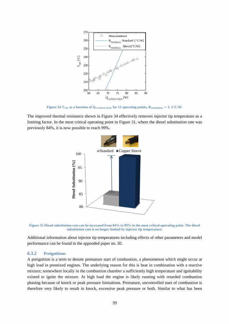
39
Figure 34 TTIP as a function of QCONDUCTION for 11 operating points, 𝑹𝑻𝑯𝑬𝑹𝑴𝑨𝑳 ≈ 𝟏.𝟏°𝑪/𝑾.
The improved thermal resistance shown in Figure 34 effectively removes injector tip temperature as a limiting factor. In the most critical operating point in Figure 31, where the diesel substitution rate was previously 84%, it is now possible to reach 99%.
Figure 35 Diesel substitution rate can be increased from 84% to 99% in the most critical operating point. The diesel substitution rate is no longer limited by injector tip temperature.
Additional information about injector tip temperatures including effects of other parameters and model performance can be found in the appended paper no. III.
6.3.2 Preignitions A preignition is a term to denote premature start of combustion, a phenomenon which might occur at high load in premixed engines. The underlying reason for this is heat in combination with a reactive mixture; somewhere locally in the combustion chamber a sufficiently high temperature and ignitability existed to ignite the mixture. At high load the engine is likely running with retarded combustion phasing because of knock or peak pressure limitations. Premature, uncontrolled start of combustion is therefore very likely to result in knock, excessive peak pressure or both. Similar to what has been
60 65 70 75 80 85 90200
210
220
230
240
250
260
270
QCONDUCTION
[W]
T TIP [ °
C]
MeasurementsR
THERMAL Standard [ °C/W]
RTHERMAL
Sleeve[°C/W]
80
85
90
95
100
Die
sel S
ubst
itutio
n [%
]
Standard Copper Sleeve
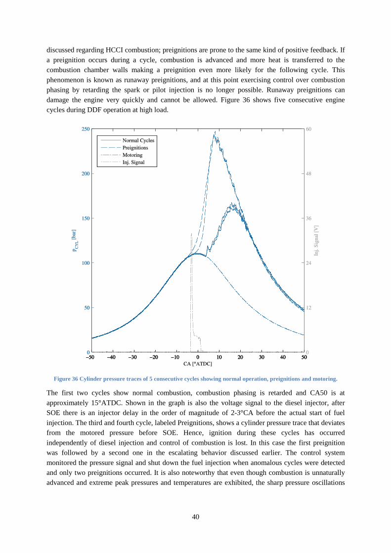
40
discussed regarding HCCI combustion; preignitions are prone to the same kind of positive feedback. If a preignition occurs during a cycle, combustion is advanced and more heat is transferred to the combustion chamber walls making a preignition even more likely for the following cycle. This phenomenon is known as runaway preignitions, and at this point exercising control over combustion phasing by retarding the spark or pilot injection is no longer possible. Runaway preignitions can damage the engine very quickly and cannot be allowed. Figure 36 shows five consecutive engine cycles during DDF operation at high load.
Figure 36 Cylinder pressure traces of 5 consecutive cycles showing normal operation, preignitions and motoring.
The first two cycles show normal combustion, combustion phasing is retarded and CA50 is at approximately 15°ATDC. Shown in the graph is also the voltage signal to the diesel injector, after SOE there is an injector delay in the order of magnitude of 2-3°CA before the actual start of fuel injection. The third and fourth cycle, labeled Preignitions, shows a cylinder pressure trace that deviates from the motored pressure before SOE. Hence, ignition during these cycles has occurred independently of diesel injection and control of combustion is lost. In this case the first preignition was followed by a second one in the escalating behavior discussed earlier. The control system monitored the pressure signal and shut down the fuel injection when anomalous cycles were detected and only two preignitions occurred. It is also noteworthy that even though combustion is unnaturally advanced and extreme peak pressures and temperatures are exhibited, the sharp pressure oscillations
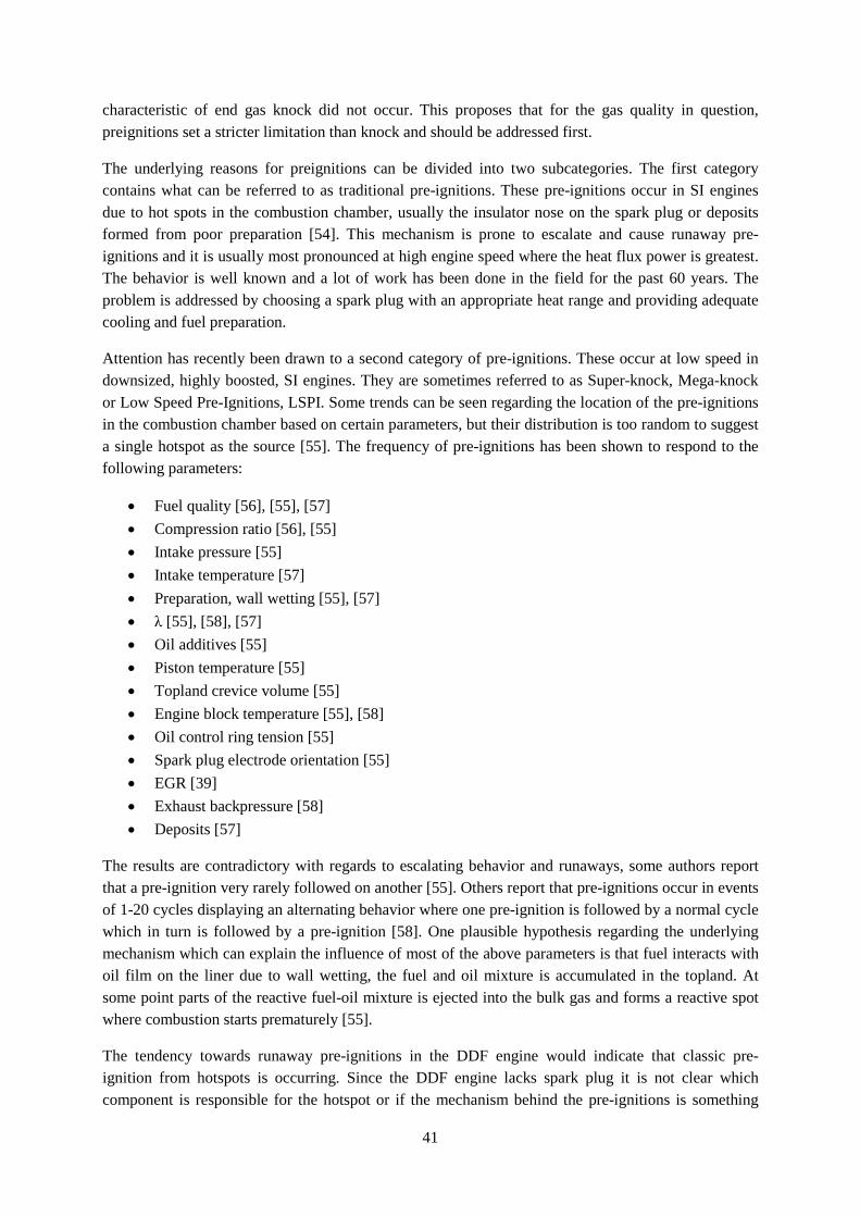
41
characteristic of end gas knock did not occur. This proposes that for the gas quality in question, preignitions set a stricter limitation than knock and should be addressed first.
The underlying reasons for preignitions can be divided into two subcategories. The first category contains what can be referred to as traditional pre-ignitions. These pre-ignitions occur in SI engines due to hot spots in the combustion chamber, usually the insulator nose on the spark plug or deposits formed from poor preparation [54]. This mechanism is prone to escalate and cause runaway pre-ignitions and it is usually most pronounced at high engine speed where the heat flux power is greatest. The behavior is well known and a lot of work has been done in the field for the past 60 years. The problem is addressed by choosing a spark plug with an appropriate heat range and providing adequate cooling and fuel preparation.
Attention has recently been drawn to a second category of pre-ignitions. These occur at low speed in downsized, highly boosted, SI engines. They are sometimes referred to as Super-knock, Mega-knock or Low Speed Pre-Ignitions, LSPI. Some trends can be seen regarding the location of the pre-ignitions in the combustion chamber based on certain parameters, but their distribution is too random to suggest a single hotspot as the source [55]. The frequency of pre-ignitions has been shown to respond to the following parameters:
• Fuel quality [56], [55], [57] • Compression ratio [56], [55] • Intake pressure [55] • Intake temperature [57] • Preparation, wall wetting [55], [57] • λ [55], [58], [57] • Oil additives [55] • Piston temperature [55] • Topland crevice volume [55] • Engine block temperature [55], [58] • Oil control ring tension [55] • Spark plug electrode orientation [55] • EGR [39] • Exhaust backpressure [58] • Deposits [57]
The results are contradictory with regards to escalating behavior and runaways, some authors report that a pre-ignition very rarely followed on another [55]. Others report that pre-ignitions occur in events of 1-20 cycles displaying an alternating behavior where one pre-ignition is followed by a normal cycle which in turn is followed by a pre-ignition [58]. One plausible hypothesis regarding the underlying mechanism which can explain the influence of most of the above parameters is that fuel interacts with oil film on the liner due to wall wetting, the fuel and oil mixture is accumulated in the topland. At some point parts of the reactive fuel-oil mixture is ejected into the bulk gas and forms a reactive spot where combustion starts prematurely [55].
The tendency towards runaway pre-ignitions in the DDF engine would indicate that classic pre-ignition from hotspots is occurring. Since the DDF engine lacks spark plug it is not clear which component is responsible for the hotspot or if the mechanism behind the pre-ignitions is something
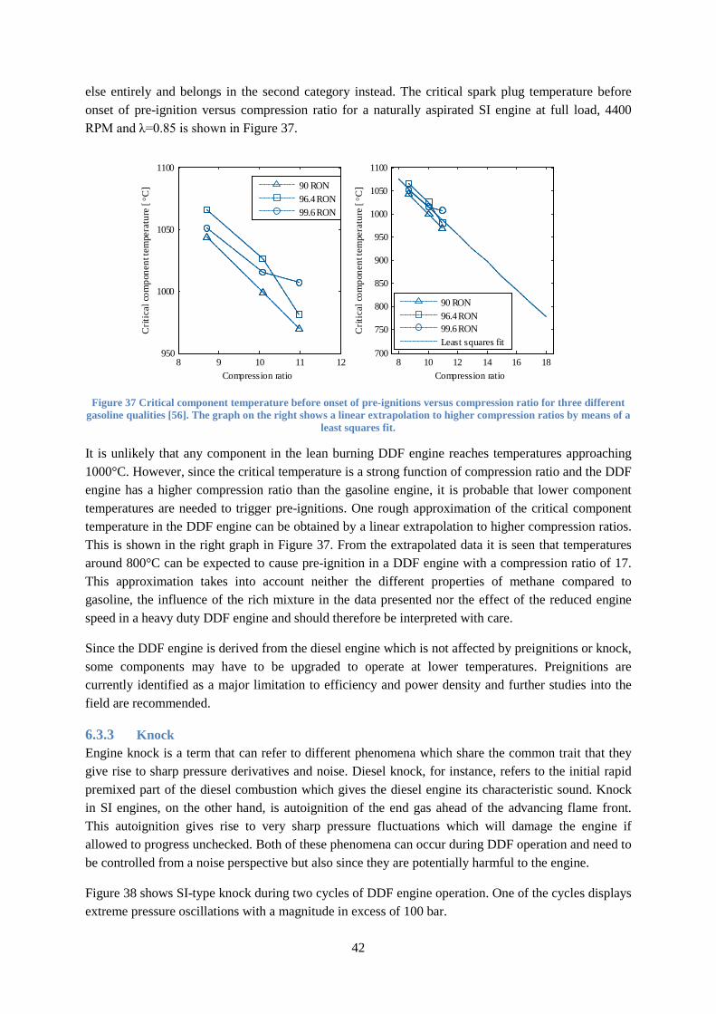
42
else entirely and belongs in the second category instead. The critical spark plug temperature before onset of pre-ignition versus compression ratio for a naturally aspirated SI engine at full load, 4400 RPM and λ=0.85 is shown in Figure 37.
Figure 37 Critical component temperature before onset of pre-ignitions versus compression ratio for three different gasoline qualities [56]. The graph on the right shows a linear extrapolation to higher compression ratios by means of a
least squares fit.
It is unlikely that any component in the lean burning DDF engine reaches temperatures approaching 1000°C. However, since the critical temperature is a strong function of compression ratio and the DDF engine has a higher compression ratio than the gasoline engine, it is probable that lower component temperatures are needed to trigger pre-ignitions. One rough approximation of the critical component temperature in the DDF engine can be obtained by a linear extrapolation to higher compression ratios. This is shown in the right graph in Figure 37. From the extrapolated data it is seen that temperatures around 800°C can be expected to cause pre-ignition in a DDF engine with a compression ratio of 17. This approximation takes into account neither the different properties of methane compared to gasoline, the influence of the rich mixture in the data presented nor the effect of the reduced engine speed in a heavy duty DDF engine and should therefore be interpreted with care.
Since the DDF engine is derived from the diesel engine which is not affected by preignitions or knock, some components may have to be upgraded to operate at lower temperatures. Preignitions are currently identified as a major limitation to efficiency and power density and further studies into the field are recommended.
6.3.3 Knock Engine knock is a term that can refer to different phenomena which share the common trait that they give rise to sharp pressure derivatives and noise. Diesel knock, for instance, refers to the initial rapid premixed part of the diesel combustion which gives the diesel engine its characteristic sound. Knock in SI engines, on the other hand, is autoignition of the end gas ahead of the advancing flame front. This autoignition gives rise to very sharp pressure fluctuations which will damage the engine if allowed to progress unchecked. Both of these phenomena can occur during DDF operation and need to be controlled from a noise perspective but also since they are potentially harmful to the engine.
Figure 38 shows SI-type knock during two cycles of DDF engine operation. One of the cycles displays extreme pressure oscillations with a magnitude in excess of 100 bar.
8 9 10 11 12950
1000
1050
1100
Compression ratio
Crit
ical
com
pone
nt te
mpe
ratu
re [
°C]
8 10 12 14 16 18700
750
800
850
900
950
1000
1050
1100
Compression ratio
Crit
ical
com
pone
nt te
mpe
ratu
re [
°C]
90 RON96.4 RON99.6 RON
90 RON96.4 RON99.6 RONLeast squares fit
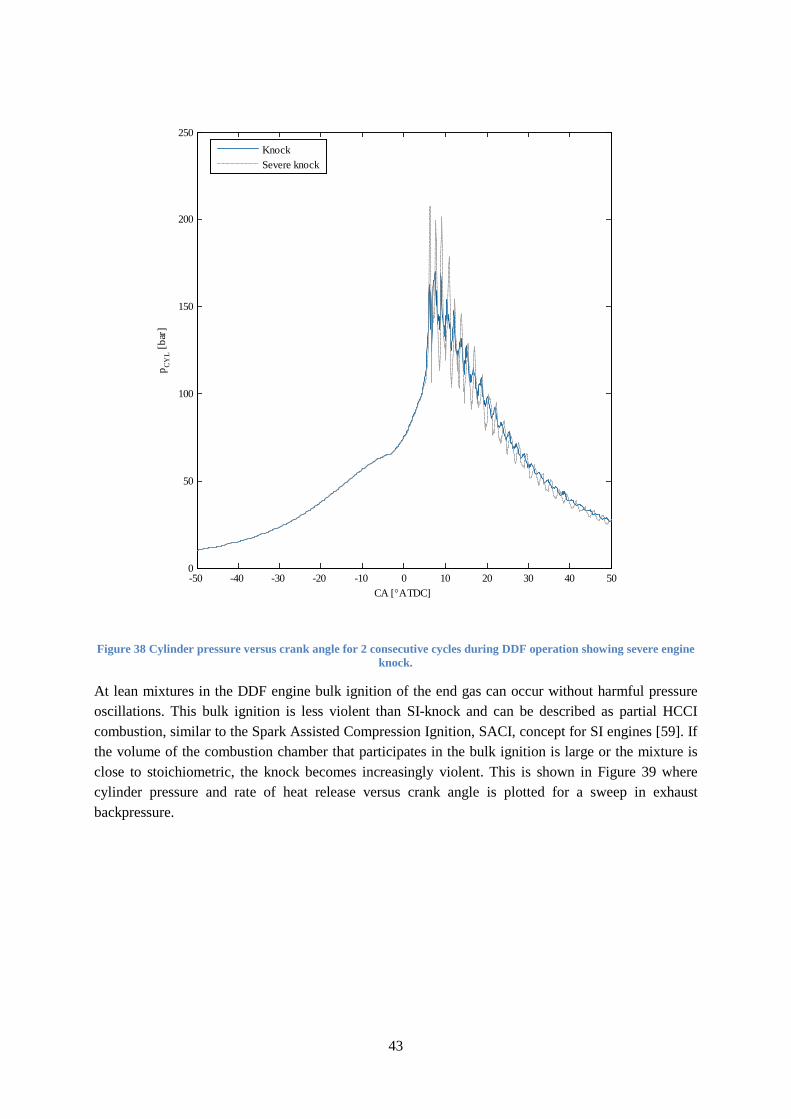
43
Figure 38 Cylinder pressure versus crank angle for 2 consecutive cycles during DDF operation showing severe engine knock.
At lean mixtures in the DDF engine bulk ignition of the end gas can occur without harmful pressure oscillations. This bulk ignition is less violent than SI-knock and can be described as partial HCCI combustion, similar to the Spark Assisted Compression Ignition, SACI, concept for SI engines [59]. If the volume of the combustion chamber that participates in the bulk ignition is large or the mixture is close to stoichiometric, the knock becomes increasingly violent. This is shown in Figure 39 where cylinder pressure and rate of heat release versus crank angle is plotted for a sweep in exhaust backpressure.
-50 -40 -30 -20 -10 0 10 20 30 40 500
50
100
150
200
250
CA [°ATDC]
p CY
L [b
ar]
KnockSevere knock
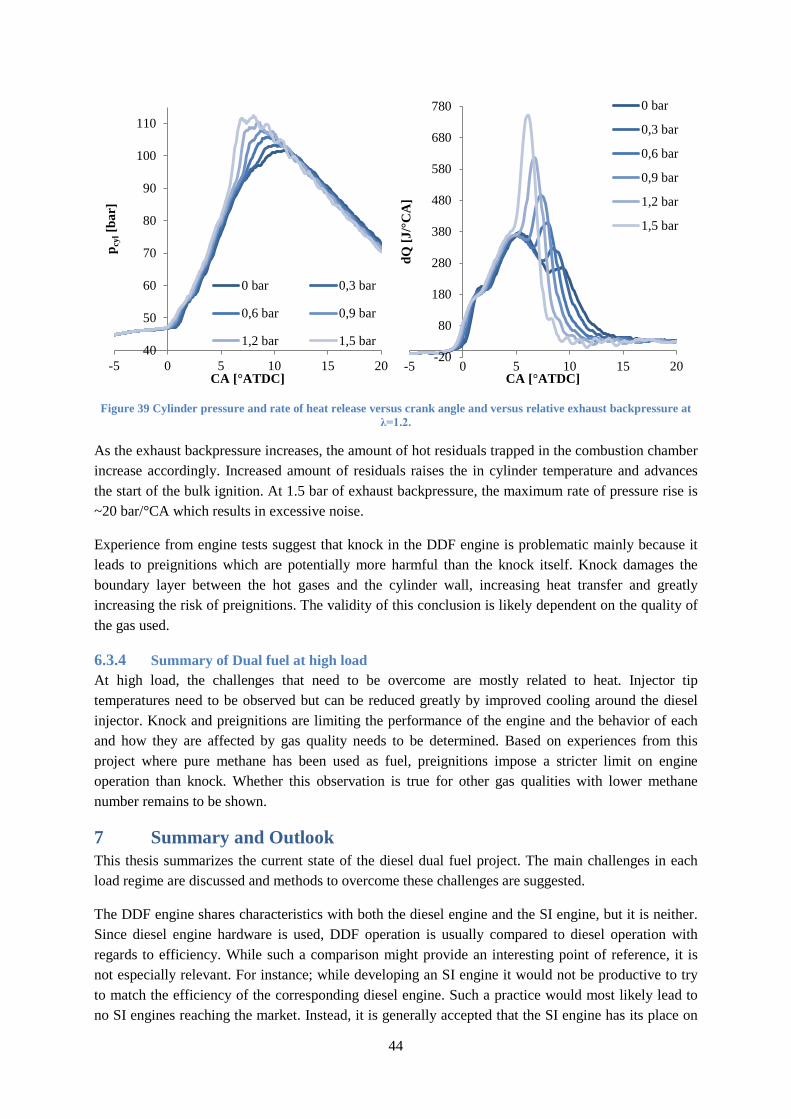
44
Figure 39 Cylinder pressure and rate of heat release versus crank angle and versus relative exhaust backpressure at λ=1.2.
As the exhaust backpressure increases, the amount of hot residuals trapped in the combustion chamber increase accordingly. Increased amount of residuals raises the in cylinder temperature and advances the start of the bulk ignition. At 1.5 bar of exhaust backpressure, the maximum rate of pressure rise is ~20 bar/°CA which results in excessive noise.
Experience from engine tests suggest that knock in the DDF engine is problematic mainly because it leads to preignitions which are potentially more harmful than the knock itself. Knock damages the boundary layer between the hot gases and the cylinder wall, increasing heat transfer and greatly increasing the risk of preignitions. The validity of this conclusion is likely dependent on the quality of the gas used.
6.3.4 Summary of Dual fuel at high load At high load, the challenges that need to be overcome are mostly related to heat. Injector tip temperatures need to be observed but can be reduced greatly by improved cooling around the diesel injector. Knock and preignitions are limiting the performance of the engine and the behavior of each and how they are affected by gas quality needs to be determined. Based on experiences from this project where pure methane has been used as fuel, preignitions impose a stricter limit on engine operation than knock. Whether this observation is true for other gas qualities with lower methane number remains to be shown.
7 Summary and Outlook This thesis summarizes the current state of the diesel dual fuel project. The main challenges in each load regime are discussed and methods to overcome these challenges are suggested.
The DDF engine shares characteristics with both the diesel engine and the SI engine, but it is neither. Since diesel engine hardware is used, DDF operation is usually compared to diesel operation with regards to efficiency. While such a comparison might provide an interesting point of reference, it is not especially relevant. For instance; while developing an SI engine it would not be productive to try to match the efficiency of the corresponding diesel engine. Such a practice would most likely lead to no SI engines reaching the market. Instead, it is generally accepted that the SI engine has its place on
40
50
60
70
80
90
100
110
-5 0 5 10 15 20
p cyl
[bar
]
CA [°ATDC]
0 bar 0,3 bar
0,6 bar 0,9 bar
1,2 bar 1,5 bar-20
80
180
280
380
480
580
680
780
-5 0 5 10 15 20
dQ [J
/°C
A]
CA [°ATDC]
0 bar
0,3 bar
0,6 bar
0,9 bar
1,2 bar
1,5 bar
45
the market, alongside the diesel engine, in spite of its lower brake efficiency. Based on the environmental concerns and supply constraints discussed in the introduction, the DDF engine likely has a niche alongside the diesel engine for HD applications and therefore does not necessarily have to compete directly in terms of brake efficiency.
As is the case with all engines depending on flame propagation, light load is a problematic area for the DDF engine. The work in this area focuses on increasing the lean limit with regards to HC emissions and hence reducing the amount of throttling needed. Increasing the lean limit in the light load range therefore immediately translates into reduced pumping losses and increased efficiency. It is shown that the best results in this area are achieved by using early diesel injection to achieve HCCI combustion. However, even without committing to HCCI combustion and the difficult control issues associated with it, substantial gains can be made simply by splitting the diesel injection into two and allocating most of the diesel fuel to the early injection.
At high load, the challenges that need to be overcome are mostly related to heat. Injector tip temperature need to be observed since the cooling effect of diesel flow through the nozzle is largely removed. This work shows that this problem can be reduced greatly by improved cooling around the diesel injector. Knock and preignitions are limiting the performance of the engine and the behavior of each and how they are affected by gas quality needs to be determined. Based on experiences from this project where pure methane has been used as fuel, preignitions impose a stricter limit on engine operation than knock. Whether this observation is true for other gas qualities with lower methane number remains to be shown.
Preignitions and knock at high load are areas of interest for future work along with an investigation into the sources of hydrocarbon emissions.
46
8 References 1. John B. Heywood, Internal Combustion Engine Fundamentals. New York: McGraw-Hill Book
Company, 1988.
2. Lars Wilderäng. (2011, Nov.) Cornucopia? [Online]. http://cornucopia.cornubot.se/2011/11/peak-oil-exports-fortfarande-2005.html
3. R. Edwards, J-F Larivé, V. Mahieu, and P. Rouveirolles, "Well-to-Wheels analysis of future automotive fuels and powertrains in the European context," 2007.
4. Christian Schwarz and Gunther P. Merker, Combustion Engines Development. Berlin: Springer-Verlag Berlin, Heidelberg GmbH & Co., 2010.
5. Mehrzad Kaiadi, Diluted Operation of a Heavy-duty Natural Gas Engine. Lund, 2011.
6. B. S. Brown, C. A. Laforet, S. N. Rogak, and S. R. Munsch, "Comparison of injectors for compression ignition of natural gas with entrained diesel", International Journal of Engine Research, vol. 12, 2011.
7. G. A. Karim, Z. Liu, and W. Jones, "Exhaust Emissions from Dual Fuel Engines at Light Load", SAE 932822, 1993.
8. U. Azimov, E. Tomita, N. Kawahara, and Y. Harada, "Premixed mixture ignition in the end-gas region (PREMIER) combustion in a natural gas dual-fuel engine: operating range and exhaust emissions", International Journal of Engine Research, vol. 12, no. 5, 2011.
9. E. Tomita, N. Fukatani, N. Kawahara, K. Maruyama, and T. Komoda, "Combustion Characteristics and Performance of Supercharged Pyrolysis Gas Engine with Micro-Pilot Ignition", Vienna, CIMAC 178, 2007.
10. Zdzislaw Stelmasiak, "The Impact of Gas-Air Composition on Combustion Parameters of Dual Fuel Engines Fed CNG", SAE 2001-01-2235, 2002.
11. Nafis Ahmad-I, M. K. Gajendra Babu, and A. Ramesh, "Experimental Investigations of Different Parameters Affecting the Performance of a CNG-Diesel Dual Fuel Engine", SAE 2005-01-3767, 2005.
12. Mohamed Y.E. Selim, "Effect of engine parameters and gaseous fuel type on the cyclic variability of dual fuel engines", Fuel, vol. 84, 2004.
13. Jie Shen, Jun Qin, and Mingfa Yao, "Turbocharged diesel/CNG Dual-Fuel Engines with Intercooler: Combustion, Emissions and Performance", SAE 2003-01-3082, 2003.
14. V. Balasubramanian, K. Sridhara, and V. Ganesan, "Performance Evaluation of a Small Agricultural Engine Operated on Dual Fuel (Diesel + Natural Gas) System", SAE 951777, 1995.
47
15. Phan Minh Duc and Kanit Wattanavichien, "Study on biogas premixed charge diesel dual fuelled engine", Energy Conversion & Management, vol. 48, 2007.
16. Seung Hyun Yoon and Chang Sik Lee, "Experimental investigation on the combustion and exhaust emission characteristics of biogas-diesel dual-fuel combustion in a CI engine", Fuel Processing Technology, vol. 92, 2011.
17. G. A. Karim, "Combustion in Gas Fueled Compression: Ignition Engines of the Dual Fuel Type", ASME, Journal of Engineering for Gas Turbines and Power, vol. 125, 2003.
18. Ghazi A. Karim, "A Review of the Combustion Process in the Dual Fuel Engine - the Gas Diesel Engine", Prog. Energy Combust. Sci., vol. 6, 1980.
19. Antonio Paolo Carlucci, Domenico Laforgia, Roberto Saracino, and Giuseppe Toto, "Study of Combustion Development in Methane-Diesel Dual Fuel Engines, Based on the Analysis of In-Cylinder Luminance", SAE 2010-01-1297, 2010.
20. Antonio P. Carlucci, Domenico Laforgia, Roberto Saracino, and Giuseppe Toto, "Combustion and emissions control ina diesel-methane dual fuel engines: The effects of methane supply method combined with variable in-cylinder bulk motion", Energy Conversion and Management, vol. 52, 2011.
21. Z. Liu and G. A. Karim, "A Predictive Model for the Combustion Process in Dual Fuel Engines", SAE 952435, 1995.
22. Nafis Ahmad-I, M. K. Gajendra Babu, and A. Ramesh, "Investigations on Combustion and Performance Characteristics of a Turbocharged Natural Gas and Pilot Ignition Dual Fuel Engine", SAE 2005-01-3775, 2005.
23. D. T. Hountalas and R. G. Papagiannakis, "Development of a Simulation Model for Direct Injection Dual Fuel Diesel-Natural Gas Engines", SAE 2000-01-0286, 2000.
24. D. T. Hountalas and R. G. Papagiannakis, "Theoretical and Experimental Investigation of a Direct Injection Dual Fuel Diesel-Natural Gas Engine", SAE 2002-01-0868, 2002.
25. R. G. Papagiannakis, D. T. Hountalas, and P. N. Kotsiopoulos, "Experimental and Theoretical Analysis of the Combustion and Pollutants Formation Mechanisms in Dual Fuel DI Diesel Engines", SAE 2005-01-1726, 2005.
26. Jin Kusaka, Norifumi Mizushima, Yasuhiro Daisho, and Takeshi Saito, "A Numerical Study on Combustion and Exhaust Gas Emissions of a Dual Fuel Natural Gas Engine Using a Multi-Dimensional Model Combined with Detailed Kinetics", SAE 2003-01-1939, 2003.
27. Jin Kusaka, Ko-ichiro Tsuzuki, Yasuhiro Daisho, and Takeshi Saito, "A Numerical Study on Combustion and Exhaust Gas Emissions Characteristics of a Dual Fuel Natural Gas Engine Using a Multi-Dimensional Model Combined With Detailed Kinetics", SAE 2002-01-1750, 2002.
48
28. Youtong Zhang, Song-Charng Kong, and Rolf D. Reitz, "Modeling and Simulation of a Dual Fuel (Diesel/Natural Gas) Engine With Multidimensional CFD", SAE 2003-01-0755, 2003.
29. Satbir Singh, Song-Charng Kong, Rolf D. Reitz, Sundar R. Krishnan, and K. Clark Midkiff, "Modeling and Experiments of Dual-Fuel Engine Combustion and Emissions", SAE 2004-01-0092, 2004.
30. Zhentao Liu and Shaomei Fei, "Emissions Prediction of CNG/Diesel Dual Fuel Engine Based on RBF Neural Network", SAE 2004-01-0646, 2004.
31. M. H. Saidi, K. Isazadeh Far, and V. Pirouzpanah, "Analysis of Combustion Process in Dual Fuel Diesel Engines: Knock Phenomenon Approach", SAE 2005-01-1132, 2005.
32. Eiji Tomita, Nobuyuki Kawahara, Zhenyu Piao, and Ryoichi Yamaguchi, "Effects of EGR and Early Injection of Diesel Fuel on Combustion Characteristics and Exhaust Emissions in a Methane Dual Fuel Engine", SAE 2002-01-2723, 2002.
33. Y. Qi, S. R. Krishnan, H. Yang, and H. C. Midkiff, "Effect of hot exhaust gas recirculation on the performance and emissions of an advanced injection low pilot-injected natural gas engine", Int. J. Engine Res., vol. 8, 2006.
34. Masahiro Shioji, Takuji Ishiyama, Makoto Ikegami, Shinichi Mitani, and Hiroaki Shibata, "Performance and Exhaust Emissions in a Natural-Gas Fueled Dual-Fuel Engine", JSME International Journal, vol. 44, no. 4, 2001.
35. B. B. Sahoo, N. Sahoo, and U. K. Saha, "Effect of engine parameters and type of gaseous fuel on the performance of dual-fuel gas diesel engines-A critical review", Renewable and Sustainable Energy Reviews, vol. 13, 2009.
36. G. H. Abd Alla, H. A. Soliman, O. A. Badr, and M. F. Abd Rabbo, "Effect of injection timing on the performance of a dual fuel engine", Energy Conversion and Management, vol. 43, 2002.
37. Z. Lin and W. Su, "A Study On The Determination of the Amount of Pilot Injection and Rich and Lean Boundaries of the Pre-Mixed CNG/Air Mixture For a CNG/Diesel Dual-Fuel Engine", SAE 2003-01-0765, 2003.
38. Inge Saanum, Marie Bysveen, Per Tunestål, and Bengt Johansson, "Lean Burn Versus Stoichiometric Operation with EGR and 3-Way Catalyst of an Engine Fueled with Natural Gas and Hydrogen Enriched Natural Gas", SAE 2007-01-0015, 2007.
39. Manfred Amann, Terrence Alger, and Darius Mehta, "The Effect of EGR on Low-Speed Pre-Ignition in Boosted SI Engines", SAE 2011-01-0339, 2011.
40. R. G. Papagiannakis, C. D. Rakopoulos, D. T. Hountalas, and D. C. Rakoupolos, "Emission characteristics of high speed, dual fuel, compression ignition engine operating in wide range of natural gas/diesel fuel proportions", Fuel, vol. 89, 2010.
49
41. Kyoungdoug Min, Wai K. Cheng, and John B. Heywood, "The Effects of Crevices on the Engine-Out Hydrocarbon Emissions in SI Engines", SAE 940306, 1994.
42. Thananchai Tepimonrat, Kittisak Kamsinla, Ekathai Wirojsakunchai, Tanet Aroonsrisopon, and Krisada Wannatong, "Use of Exhaust Valve Timing Advance for High Natural Gas Utilization in Low-Load Diesel Dual Fuel Operation", SAE 2011-01-1767, 2011.
43. W. K. Cheng et al., "An Overview of Hydrocarbon Emissions Mechanisms in Spark-Ignition Engines", SAE 932708, 1993.
44. Neil D. Thompson and James S. Wallace, "Effect of Engine Operating Variables and Piston and Ring Parameters on Crevice Hydrocarbon Emissions", SAE 940480, 1994.
45. A. C. Alkidas, R. J. Drews, and W. F. Miller, "Effects of Piston Crevice Geometry on the Steady-State Engine-Out Hydrocarbon Emissions of a S.I. Engine", SAE 952537, 1995.
46. Masayuki Tamura, Teruhiro Sakurai, and Hideo Tai, "A Study of Crevice Flow in a Gas Engine using Laser-induced Fluorescence", SAE 2001-01-0913, 2001.
47. R. Backman, "Open Source Rapid Prototyping Environment", SAE 2011-01-0711, 2011.
48. Tunestål, "Self-tuning gross heat release computation for internal combustion engines.", Control Engineering Practice, vol. 17, 2009.
49. Mitsuro Konno and Zhili Chen, "Ignition Mechanisms of HCCI Combustion Process Fueled with Methane/DME Composite Fuel", SAE 2005-01-0182, 2005.
50. N. Ladommatos, P. Aleiferis, S. Zülch, N. Milovanovic, V. Lafon, A. Orlovic, P. Lacey and P. Richards A. Birgel, "Deposit Formation in the Holes of Diesel Injector Nozzles: A Critical Review", SAE 2008-01-2383, 2008.
51. S. Dehoux, P. Gastaldi, L. Grosjean, F. Levy, A. Michel, D. Passerel B. Argueyrolles, "Influence of injector nozzle design and cavitation on coking phenomenon", SAE 2007-01-1896, 2007.
52. O. Kazuhiro, K. Nakai, R. Ueda, N. Kakehashi, K. Sunami M. Ikemoto, "Injection Nozzle Coking Mechanism in Common-rail Diesel Engine", SAE 2011-01-1818, 2011.
53. M. Pfitzner, M. Frobenius R. Leuthel, "Numerical Study of Thermal-Fluid-interaction in a Diesel Fuel Injector", SAE 2008-01-2760, 2008.
54. Kazuhisa Mogi, Katsushi Hashizume, Katsuhiko Arisawa, and Hideo Kobayashi, "Analysis and avoidance of pre-ignitions in S.I. gasoline engines", JSAE, vol. JSAE Review, no. 19, 1998.
55. Akram Zahdeh et al., "Fundamental Approach to Investigate Pre-Ignition in Boosted SI Engines", SAE 2011-01-0340, 2011.
50
56. Nozimi Sasaki et al., "The Effect of Fuel Compounds in Pre-ignition under High Temperature and High Pressure Condition", SAE 2011-01-1984, 2011.
57. Patrick Haenel, Philipp Seyfried, Henning Kleeberg, and Dean Tomazic, "Systematic Approach to Analyze and Characterize Pre-ignition Events in Turbocharged Direct-injected Gasoline Engines", SAE 2011-01-0343, 2011.
58. Manfred Amann, Darius Mehta, and Terrence Alger, "Engine Operating Condition and Gasoline Fuel Composition Effects on Low-Speed Pre-Ignition in High-Performance Spark Ignited Gasoline Engines", SAE 2011-01-0342, 2011.
59. L. Manofsky, J. Vavra, D. Assanis, and A. Babajimopoulos, "Bridging the Gap between HCCI and SI: Spark Assisted Compression Ignition", SAE 2011-01-1179, 2011.
51
Definitions/Abbreviations
AFRdiesel Stoichiometric air to fuel ratio for diesel
AFRmethane Stoichiometric air to fuel ratio for methane
ATDC After Top Dead Center BMEP Brake Mean Effective Pressure BSCO Brake Specific emissions of Carbon monoxide BSHC Brake Specific Hydrocarbon emissions BSNOX Brake Specific emissions of nitrogen oxides BTDC Before Top Dead Center CA Crank Angle CA50 Crank Angle of 50% heat release CI Compression Ignited CNG Compressed Natural Gas CO Carbon monoxide CO2 Carbon dioxide CoV Coefficient of Variation DDF Diesel Dual Fuel DI Direct Injection DME Dimethyl Ether DPF Diesel Particulate Filter ECM Engine Control Module EGR Exhaust Gas Recirculation EVC Exhaust Valve Closing EVO Exhaust Valve Opening FT Fischer-Tropsch GHG Greenhouse Gas GUI Graphical User Interface HC Unburned hydrocarbons HCCI Homogenous Charge Compression Ignition HD Heavy Duty IVC Intake Valve Closing IVO Intake Valve Opening LSPI Low Speed Pre-Ignition MBT Maximum Brake Torque NG Natural Gas NOx Oxides of nitrogen; nitric oxide and nitrogen
PPCI Partially Premixed Compression Ignition RCCI Fuel Reactivity Controlled Compression Ignition RPM Revolutions Per Minute SACI Spark Assisted Compression Ignition SI Spark Ignited SOE Start Of Energizing TDC Top Dead Center WTW Well To Wheel λ Air excess ratio