Embed Size (px)
Citation preview
(7 7 Report No.
WPR (NASC) TR-79-1
AERO-SERVO-ELASTICSTABILITY ANALYSIS
byWilliam P. Rodden, Mildred R. Zeifman
andJohn M. Powers, Jr.
Prepared forDEPARTMENT OF THE NAVY
NAVAL AIR SYSTEMS COMMANDWashington, D.C. 20361
UnderContract N0001 9-76-C-0346
April 1979
DISTRIBUTION UNLIMITED:APPROVED FOR PUBLIC RELEASE

DISCLAIMER NOTICE
THIS DOCUMENT IS BEST QUALITYPRACTICABLE. THE COPY FURNISHEDTO DDC CONTAINED A SIGNIFICANTNUMBER OF PAGES WHICH DO NOT
REPRODUCE LEGIBLY.
I !.

Repo"t NO.
WPR (NASC) TR- 79-1
AERO-SERVO- ELASTICSTABILITY ANALYSIS
byWilliam P. Rodden, Mildred R. Zeifman
andJohn M. Powers, Jr.
Prepared forDEPARTMENT OF THE NAVY
NAVAL AIR SYSTEMS COMMANDWashington. D.C. 20361
UnderContract NOOO1 9-76-C-0346
April 1979
DISTRIBUTION UNLIMITED:IAPPROVED FOR PUBLIC RELEASE
SWCUPAlV CLASSIFICATION OF TWIS 104419 (Who Dae. Entered)
PAGE READ INSTRUCTIONSREPORT DCUMENTATION PAEDEFORE COMPLETING FORM
1106111V NumiaER j. GOVT ACCIESSION NO. 3. RICIPIENTVS CATALOG HUMIIIER
*..*4TLC (41"d 5aubaeatejTp Iraf TaDn
Stabili(?y Anlsi.Final ept, 6 Aprin76 -
I. ~ -1. CON-RACT OR GRANT NUMISERWO)
J" L illim P./Aodden, Mildred R./Zeifman and ,--JNfJ0019-76-C-0346'/ ,L jh JP~rJr. -''7/ I__ *
S. ERORMING ORGANIZATION N4AME AND ADDRE9Sy 0.ROAMLMNTPOJC.AK
(Wllism P )i!Rodden, a*~u ' AES OCUI U5R255 Starlijlt Crest DriveLa Ca1'aa l dss CA 91011
11. CONTROLLING OFFICE NAME AND ADDRESS IZ. REPORT DATE
Department of the Navy 21 July 1977Naval Air Systems Coumand Is. kUMSE OF PA39S
Washington, D.C. 20361______________14. MONITORING AGENCY 4AMEL A AODR3S(il dittoe..t from CofltroZinad 0111 cc) IS. SECURITY CLASS. (of this repori)
t - UNCLASSIFIED
J' IS& /ELSIrCTO!ONR~NSCHEDULE
IS ISTRIOUTION STATEMENT (of is Report)
DISTRIBUTION UNLIMITED: APPROVED FOR PUBLIC RELEASE
17. OISTRIUIUTIO4 STATE[MaNT (at me. abstrct enltered In Stock 20. II diliereflt freom Report)
10. SUPPLEMENTARY NOTES
It. KEY WORDS (Continue onl towers* aide 1 iffl*0*0d& aid Ideifyj~ &V block number)
Aer-servo-laticityAsroelasticityStructural Dynamics
Control System Stability5~STRACT (fihnlnuo en reveriee side of ne~tcssar end Identify or block number)
A georal matrix formulation of the aero-servo-elastic stability problemis presented based on the British method of flutter analysis. The analysisapplies to the closed-loop system, and the digital computer program (HPASES)developed to perform the analysis is described. An application is madeto a typical air-to-air missile with three feedback loops.
DO I JH17 1473 EDITION oil I Nov 6 s as otSOrTE I 1Q *>
SECURITY CLASSIFICATION OF THIS PAGE (Whlen Doe Entered)
SLM44AY
A general matrix formulation of the aero-servo-elastic stability
problem for a closed-loop system is presented. It is based on a classi-
cal method for determining servomechanism stability (using linear
differential equations) and the British method of flutter analysis which
represents the aerodynamic forces as frequency dependent springs and
dampers. The combination of the aerodynamic forces with the mechanical
springs and dampers in the equations of motion and then with their
electro-mechanical equivalents in the servo system leads to a consistent
formulation of the linear equations of motion for the closed-loop aero-
servo-elastic system. An iterative real eigenvalue solution accounts
for the frequency dependence of the aerodynamic forces which is only
secondary.
The digital computer program MPASES Cmodified program for aero-
servo-elastic stability) developed to perform the analysis is described.
Dynamic storage allocation is utilized throughout MPASES to provide the
most efficient use of core storage through the variable dimensioning of
all arrays. Program limitations are minimal allowing stability results
in one computer run to be obtained for up to ten velocities at each of
five altitudes. In addition, as many as twenty-five servo element gain
va~1ation, are peatitted.
41p-,,
. x , ,. L. . .. . . . . ¢ , i, - - , t -- .. .. .. i. ._ .2 . . .. . .. .. .. .. . .... i'lI
II [I II I I III I I"0i
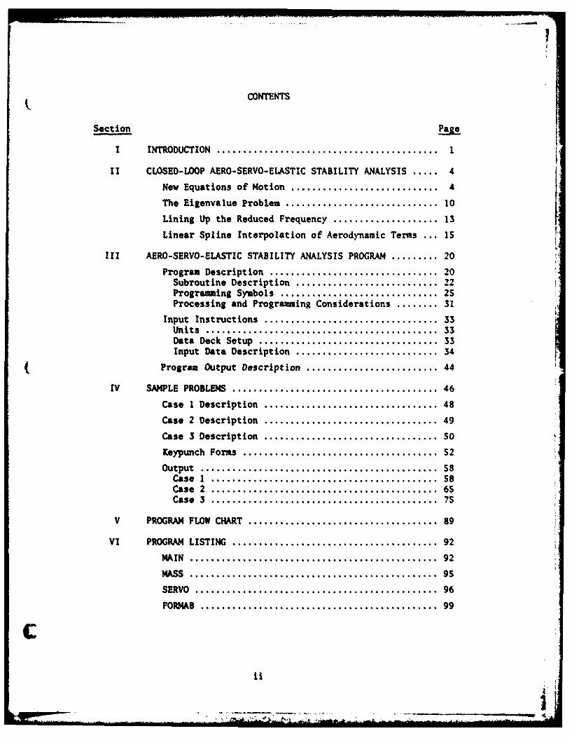
CONTENTS
Sect ion Pg
I INTRODUCTION .. . . . . . . . . . .. . . . . . . . . . 1
II CLOSED-LOOP AERO-SERVO-ELASTIC STABILITY ANALYSIS ....... 4
New Equations of Motion ............................ 4
The Eigenvalue Problem ............................ 10
Lining Up the Reduced Frequency .................... 13
Linear Spline Interpolation of Aerodynamic Terms ... 15
III AERO-SERVO-ELASTIC STABILITY ANALYSIS PROGRAM .......... 20
Program Description ............................... 20Subroutine Description .......................... 22Programming Symbols............................. 25Processing and Programming Considerations .........31
Input Instructions ................................ 33Units ........................................... 33Data Deck Setup ................................. 33Input Data Description ...........................34
Program Output Description .........................44
IV SAMPLE PROBLEMS ...................................... 46
Case I Description ................................ 48
Case 2 Description ................................ 49
Case 3 Description ................................ SO
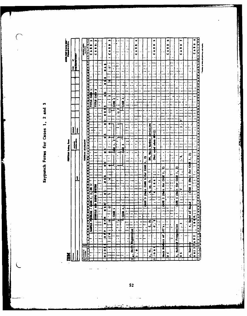
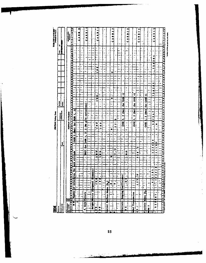
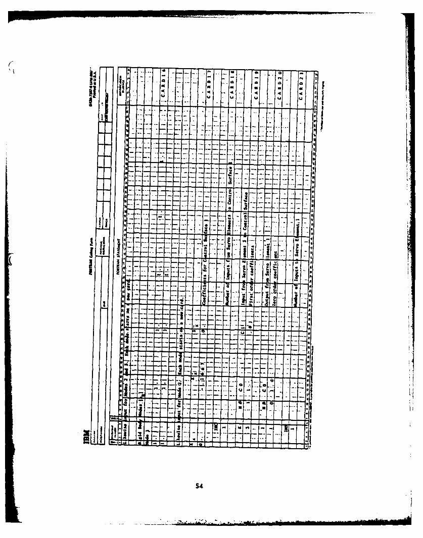
Keypunch Forms .................................... 52
output ............................................ 58Case 1 ..........................................58eCase2 .......................................... 65Case 3 .......................................... 75
V PROGRAM FLOW CHART ................................... 89
VI PROGRAM LISTING ...................................... 92
MIAIN............................................. 92
MIASS............................................. 95
SERVO............................................ 96
FORI4AB ............................................ 99
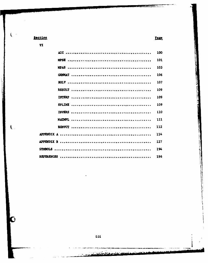
ection baze
W~AS * *.*..*.* * ****......,. 103
SY1~ESUL ****.*****.**e****.*..*ooooo.*.e*a****o...* 19
INTERP 10
SPLINE 10
INVERS 11MAHP Ill-- - --- ~ n - --
ZGN=~~~~~~~ ooo4oooo~oooeoo~ooeo*o 1
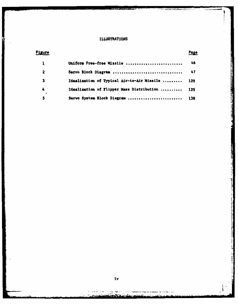
I LLUSTRATIONS
F inurePage
1 IUniform Free-free Missile .............. 46
Servo Block Diagram . . .... *S****........ .... 47
3 Idealization of Typical Air-to-Air Missile .... 129
4 Idealization of Flipper Mass Distribution ...... 129
S Servo System Block Diagram ............ 138
iv
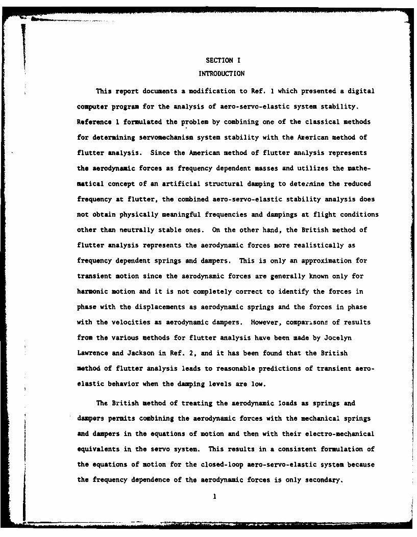
SECTION I
INTRODUCTION
This report documents a modification to Ref. 1 which presented a digital
computer program for the analysis of aero-servo-elastic system stability.
Reference 1 formulated the problem by combining one of the classical methods
for determining servomechanism system stability with the American method of
flutter analysis. Since the American method of flutter analysis represents
the aerodynamic forces as frequency dependent masses and utilizes the mathe-
matical concept of an artificial structural damping to detetmine the reduced
frequency at flutter, the combined aero-servo-elastic stability analysis does
not obtain physically meaningful frequencies and dampings at flight conditions
other than neutrally stable ones. On the other hand, the British method of
flutter analysis represents the aerodynamic forces more realistically as
frequency dependent springs and dampers. This is only an approximation for
transient motion since the aerodynamic forces are generally known only for
harmonic motion and it is not completely correct to identify the forces in
phase with the displacements as aerodynamic springs and the forces in phase
with the velocities as aerodynamic dampers. However, comparlsons of results
from the various methods for flutter analysis have been made by Jocelyn
Lawrence and Jackson in Ref. 2, and it has been found that the British
method of flutter analysis leads to reasonable predictions of transient aero-
elastic behavior when the damping levels are low.
The British method of treating the aerodynamic loads as springs and
dampers permits combining the aerodynamic forces with the mechanical springs
and dampers in the equations of motion and then with their electro-mechanical
equivalents in the servo system. This results in a consistent formulation of
the equations of motion for the closed-loop aero-servo-elastic system because
the frequency dependence of the aerodynamic forces is only secondary.
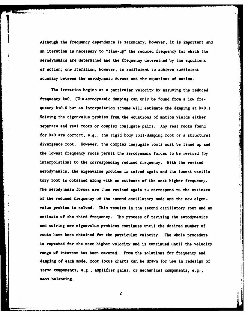
Although the frequency dependence is secondary, however, it is important and
an iteration is necessary to "line-up" the reduced frequency for which the
aerodynamics are determined and the frequency determined by the equtions
of motion; one iteration, however, is sufficient to achieve sufficient
accuracy between the aerodynamic forces and the equations of motion.
The iteration begins at a particular velocity by assuming the reduced
frequency k=O. (The aerodynamic damping can only be found from a low fre-
quency kO.O but an interpolation scheme will estimate the damping at k-O.)
Solving the eigenvalue problem from the equations of motion yields either -
separate and real roots or complex conjugate pairs. Any real roots found
for kuO are correct, e.g., the rigid body roll-damping root or a structural
divergence root. However, the complex conjugate roots must be lined up and
the lowest frequency roots permit the aerodynamic forces to be revised (by
interpolation) to the corresponding reduced frequency. With the revised
aerodynamics, the eigenvalue problem is solved again and the lowest oscilla-
tory root is obtained along with an estimate of the next higher frequency.
The aerodynamic forces are then revised again to correspond to the estimate
of the reduced frequency of the second oscillatory mode and the new eigen-
value problem is solved. This results in the second oscillatory root and an
estimate of the third frequency. The process of revising the aerodynamics
and solving new eigenvalue problems continues until the desired number of
roots have been obtained for the particular velocity. The whole procedure
is repeated for the next higher velocity and is continued until the velocity
range of interest has been covered. From the solutions for frequency and
damping of each mode, root locus charts can be drawn for use in redesign of
servo components, e.g., amplifier gains, or mechanical components, e.g.,
mss balancing.
The modified program for aero-servo-elastic stability (MPASES) requires
four revisions to the program PASES of Ref. 1. The first is the inclusion
of the aerodyna . forces as spring and damping terms in the equations of
motion rather than as complex inertial terms. The second is the iterative
eigenvalue solution required to line up the frequencies between the aero-
dynamic forces and the equations of motion as tiscussed above. The third
problem is the interpolation of the aerodynamic forces necessary in the
iteration to minimize aerodynamic computational expense. The last problem
is the result of the new formulation dealing only with real matrices; a
specialized eigenvalue extraction method that analyzes real matrices which
have either real or complex conjugate roots may be utilized for computational
efficiency. Each of these modifications is discussed in the following sections.
3-
3 '
"7 SECTION II
CLOSED-LOOP AERO-SERVO-ELASTIC STABILITY ANALYSIS
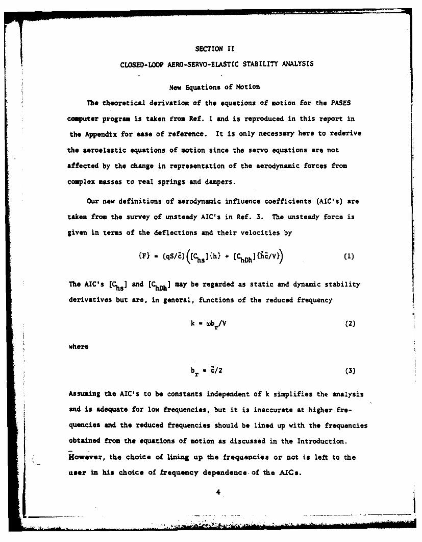
New Equations of Motion
The theoretical derivation of the equations of motion for the PASES
computer program is taken from Ref. 1 and is reproduced in this report in
the Appendix for ease of reference. It is only necessary here to rederive
the aeroelastic equations of notion since the servo equations are not
affected by the change in representation of the aerodynamic forces from
complex masses to real springs and dampers.
Our new definitions of aerodynamic influence coefficients (AIC's) are
taken from the survey of unsteady AIC's in Ref. 3. The unsteady force is
given in terms of the deflections and their velocities by
The AIC's [Chs ] and [ChDh] may be regarded as static and dynamic stability
derivatives but are, in general, fLnctions of the reduced frequency
k wb /V (2)r
where
br /2 (3)
Assuming the AIC's to be constants independent of k simplifies the analysis
and is adequate for low frequencies, but it is inaccurate at higher fre-
quencies and the reduced frequencies should be lined up with the frequencies
obtained from the equations of motion as discussed in the Introduction.
However, the choice of lining up the frequencies or not is left to the
user in his choice of frequency dependence of the AICI.
41Igg "2- j.ai
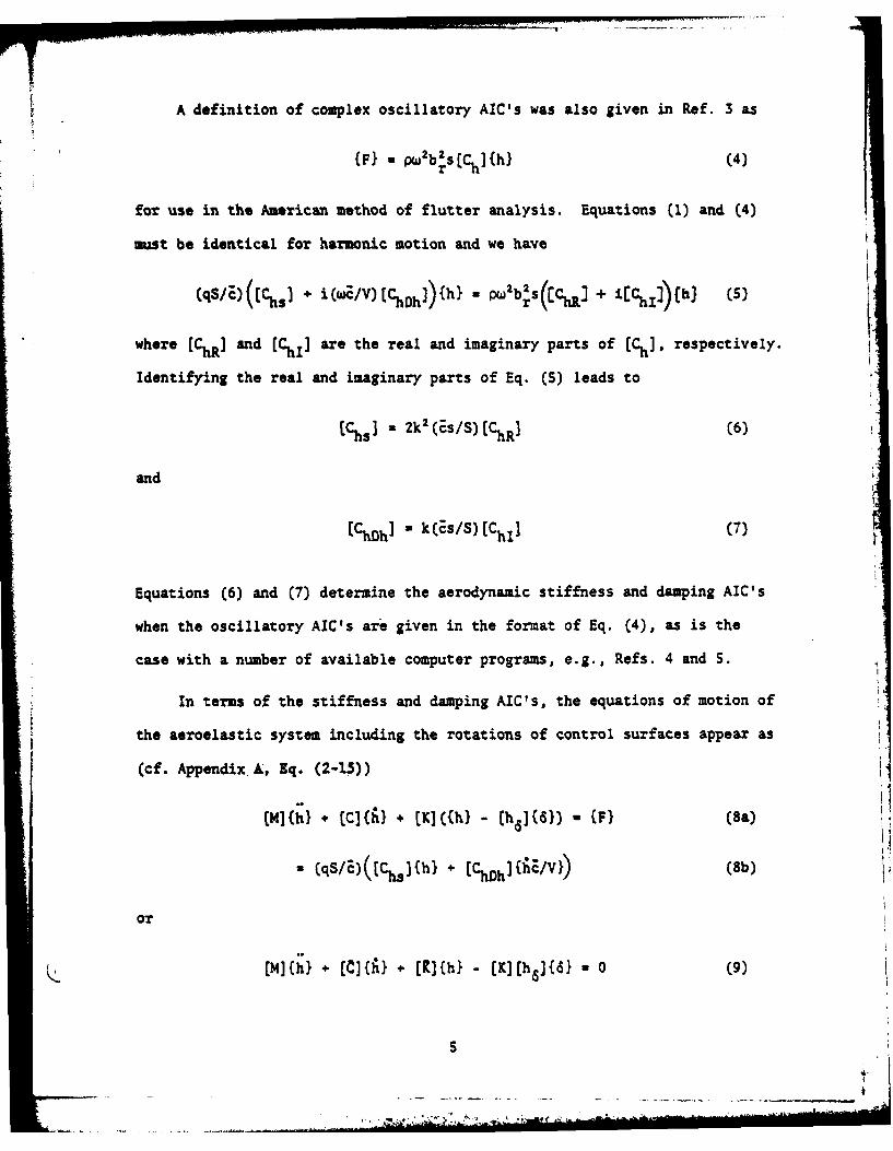
Adefinition ofcmlxoclaoyACswas also given in Ref. 3 as
WF - PW 2b 2SC](h}(4
for use in the American method of flutter analysis. Equations (1) and (4)
must be identical for harmonic motion and we have
(qS/z)([Ch5J + i(wc/V)[CSh]){hl . pW2 b 2S(ECR + .9- ]C (5)
where (ChR] and (CMI] are the real and imaginary parts of (Ch] respectively.
Identifying the real and imaginary parts of Eq. (S) leads to
(Chs] 2k 2 (Es/S) [ChR] (6)
and
[ChDh1 kCEs/S)(C hI] (7)
Equations (6) and (7) determine the aerodynamic stiffness and damping AIC's
when the oscillatory AIC's are given in the format of Eq. (4), as is the
case with a number of available computer programs, e.g., Refs. 4 and S.
In terms of the stiffness and damping AIC's, the equations of motion of
the aeroelastic system including the rotations of control surfaces appear as
(cf. Appendix.A, Eq. (2-15))
(M](h} + (C](fi} + (K]({hl - (ha](6}) u(}(8a)
-(qS/E)([Chsj(h} + 1(SDh){E/V}) (8b)
or
Q (14(h} + (CJ(A} + (K](hl (K](h 6]l - 0 (9)
where
[C C] - PVS(Chh] (0
[R] C K] - CqS/E)(Ch] (1
The modal solution proceeds as before (see Appendix L). The series for
the deflections is
Wh - (hh1f a ) + (hp]{aR} + [h61{61 (12)
Substituting Eq. (12) into Eq. (9) anid pTOMUltiplying by (hF]T leads toF3.
the modal equations for the flexible degrees of freedom.
4- It (13)(F](aFl [tR.R + btFdJ (13
+*J (]ad} IJFR1 N) + 1( a)tS 0
where
IMF] - [hF] T([M]hF] (14)
(MFR] - hF]T(M](hR] (15)
IMF,] - (h,]T(M](hs] (16)
[h (]T C](hR (lea)
UaR 1 R
a hpSh 1T ~~h h I(1b
[FS - [hF]T[C] [ha] (19a)
A -IPVS[hF] TChvh] (h6] (19b)
C1F] [ [hF]T[C]hF] (20)
(jtFRJ [hF]T(R hR] (21a)
- -(qS/E)EhF] T (Chs] ChR] (21b)
(tFa - thF3T JR11h6l (22a)
= -(qS/E) h (F]T[Chs] [hs] (22b)
Equation (13) may be compared to Eq. (2-20) in Appendix A. We have utilized
the fact above that the rigid body displacements cause no internal damping or
structural forces. We have assumed the vibration modes are either free-free
modes for the entire system or restrained modes for individual components,
but may not be arbitrarily chosen modes. The limited orthogonality of the
free-free or restrained modes (i.e., [tMF] is not a diagonal matrix unless
all modes are free-free modes) leads to a diagonal form for the generalized
stiffness matrix rKFj. If we denote the diagonal elements of [V.] by fMFJ,
then the generalized stiffness matrix is
rxF- [hF]T[K](hF] (23a)
a [(23b)
and
( •~ * - (qS/E)[h] [hF] (24)
7
The generalized structural damping matrix does not have a diagonal form, as
does the generalized stiffness, but is assumed so as an approximation that is
Justified by low levels of structural damping. The approximate form of the
equivalent viscous structural damping is
rcFJ - L'F/'WP'XFI (25a)
fCFI rgF/ yF J (2Sb)
so that
Ea,) fC J - VpVS[hF][Ch~h](hp] (26)
Next, substituting Eq. (12) into Eq. (9) and premultiplying by (hR]T
leads to the modal equations for the rigid body degrees of freedom.
(MRF]I(!F} + (MR] {MR + (MR6] {tS
" (IaIFI( +~(~ [ CR]'R IRd(S) (27)
" (.a) + (kit] {N) (R 8](6) 0
where
,J " ,(28)
SR,]. [hR] T t4] [hR1] (29)
(MMRJ - [hRIT[t] [h 6 1 (30)
(;] . ChR]T[] Ch,] (31a)
I IOVS(hR ]TChDh hF] (31b)
8~ *
h- j-Tt [h(j_ (32a)
S- 4pVS~hRJ T [ChDh ]hR (32b)
[;6] ChR]T[C] [h6 ] (33a)
= - 4pVS[hR]TChDh ](h6] (33b)
tNFI - hIT (] [hF] (34a)
C(qS/E)[hR T [ ]hF I (34b)
*kI [hR)T (R] ChR] (35a)
= -(qS/c) [hR] T (Chs (hR] (5b)
[kRu] [ [hR]T(Chs] [h6] (36a)
-(qS/c)hRI Chs ] [h6 ] (36b)
and we have again noted that rigid body displacements produce no internal
damping or structural forces. Equation (27) should be compared to Eq. (2-29)
in Appendix A.
The new matrix partitions in the aero-servo-elastic equations of motion
now become
[MFI~~~~ -NR
IF ) I
a 11 [[ (MR] (MR6] 'RCK3j](Wi - aR (37)
0 0 Ccj CS2]
PLFSAJ LRSAJ (SC] [SS2], i2
9
• -. . . . . . .* .. * . ... .... ........ . .-
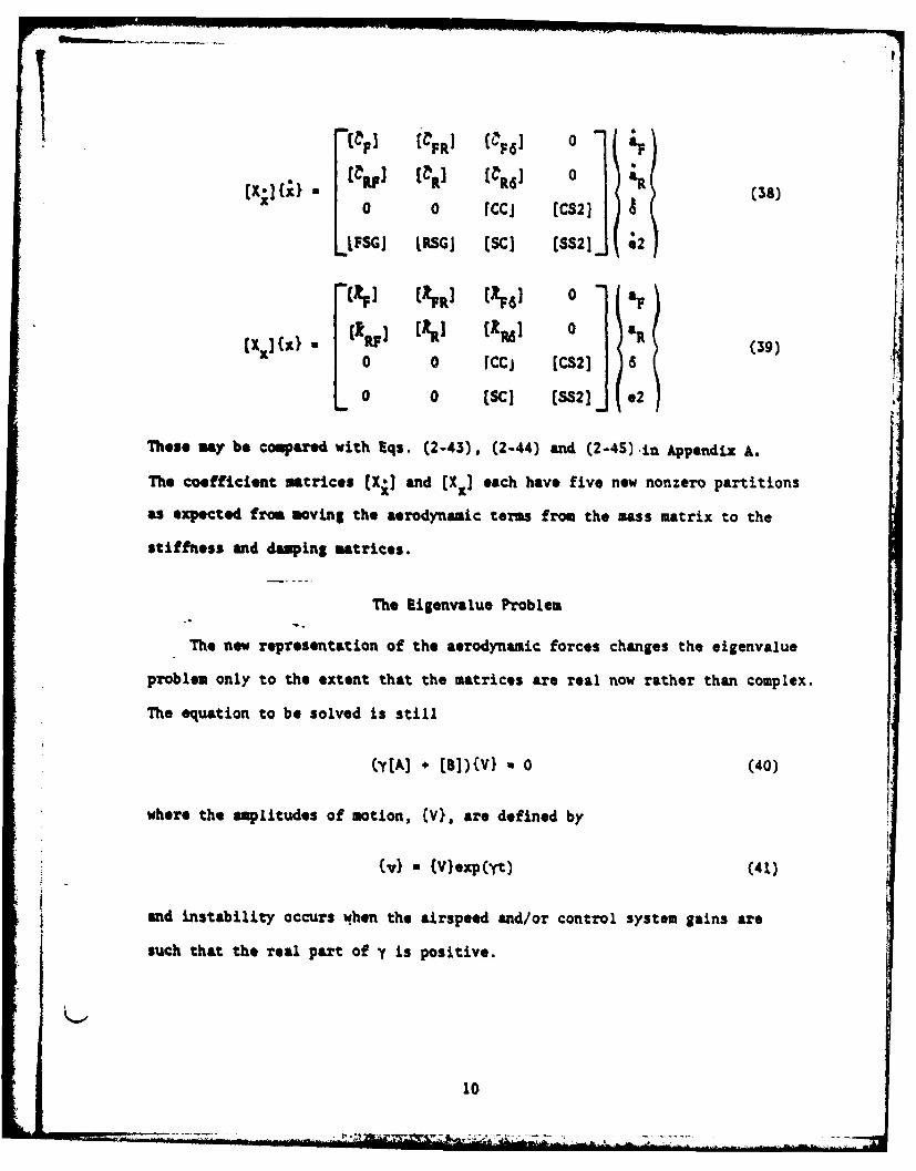
*XlItl (YF p"R (R61 0R (38)0 c 0 (CC [CS2] AI
LFSGI LRSGJ [SCI (SS2. ;2
~FJ (ku c;FO 0 af
(X X)- [I Ril Cl (Z 0 SR (39)0 0 rCCj [CS2] 8
0 0 (SC] [SS2J .2
These may be compared with Eqs. (2-43), (2-44) and (2-45) -in Appendi A.
The coefficient matrices (X;] and (Xx] each have five new nonzero partitions
as expected from moving the aerodynamic terms from the mass matrix to the
stiffness and damping matrices.
The Eigenvalue Problem
The new representation of the aerodynamic forces changes the eigenvalue
problem only to the extent that the matrices are real now rather than complex.
The equation to be solved is still
(y(A] + [B])(V} % 0 (40)
where the amplitudes of motion, (V), are defined by
(vI - (V}eCxpyt) (41)
and instability occurs when the airspeed and/or control system gains are
such that the real part of y is positive.
10
Although (A] and [B] are now real matrices, they still may be singular
and obtaining the canonical form of the eigenvalue problem by a shift in
eigenvalues is still appropriate. We let
Y U YO - l/A (42)
where y is an arbitrarily chosen real number, and then the new eigenvalue is
a 1/Cy o - y) (43)
and the new eigenvalue problem is
-- A N CYo[A] (B])'[A](V} (44)
The shift value yo is arbitrary to the extent that it must be chosen so the
linear combination ya[A] + CB] is nonsingular. A value which scales [A) to
be the sam order of magnitude as [B] and of the same sign is recommended.
The eigenvalues of Eq. (44) are either real or complex conjugates. A V
subroutine ALLMAT (Ref. 6) for complex matrices was used in Ref. 1.
A more recent development for the real case of Eq. (44) is the sub-
routine LIGRP given in the International Mathematical and Statistical Library
(UL, Ref. 7). Subroutine EIGRJ calls I14SL routine EBALAF to balance the
matrix. Then INSL routine EISS reduces the balanced matrix to an upper
Hessenber8 form and routine EQIM3 computes all of the real and/or complex
conjugate pairs of eigervalues of the essenberg matrix.
The IfML Packap is universally used and is usually incorporated into
the scientific libraries of major computer systems. When requested, the
eigeuvectors are found in two iterations by the Inverse Power Method with
Shifts (Ref. 8, pp. 323, 626-628) in subroutine E QVCT (Ref. 9). Subroutine
11
908VC finds the sigeuvector (u) from a complex matrix [u] and its complex
eigevalue A by solving the equation
[U - AIJ(u) - 0 (4S)
The subroutine is used in the present development by setting
A -o (46)
and
[U] y y[A] [B] (47)
in Eq. (45). If eigenvectors are requested, all real eigenvalues are used
in Eq. (47), but only the complex conjugate eigenvalues with positive
imaginary parts (positive frequencies) are used, since the eigenvectors are
also complex conjugate pairs.
Writing the complex eigenvalue as
Y a * + iW (48)
where 0 is the decay rate and w is the damping frequency, we find the cyclic
frequency to be
f a w/2w (49)
and the fraction of critical damping C to be
C - * (" (SO)
For comparison to structural damping levels, twice the damping ratio C is
a preferable output quantity since
C- g/2 (s)
12
for a structurally-damped single degree of freedom oscillator. For a non-
oscillatory root a different definition of damping ratio is necessary and
we chose the time to half amplitude
T (S2)
If the motion is unstable, i.e., V > 0, Eq. (52) gives the (negative) time
to double amplitude. The stability of the oscillatory roots can also be
compared using Eq. (52) and this will be an additional output quantity.
Lining Up the Reduced Frequency
The need for lining up the reduced frequency for a specified mode of
motion with the frequency determined by the eigenvalue problem for that mode
was discussed briefly in the Introduction and at some length in Ref. 2. The
necessary equations for the iteration are given in this section.
It is possible to begin the iteration with any value of k. However, a
finite value of k may be representative of an oscillatory mode but we are
equally interested in static modes. Therefore, we begin with knO and any
real roots will be determined, e.g., the roll-damping root, a static struc-
tural divergence root, and any over-damped roots from control system compon-
ents. The first oscillatory root for a free vehicle may be either the short
period mode or the Dutch roll mode and the choice of k-O provides a good
estimate of that.
Let the complex conjugate pairs of roots be denoted by
Yrs a urs ± iWrs (53)
where r denotes the oscillatory mode number ordered by frequency,
(w15 <2s < "" ) and s denotes the number of the mode under investigation.
13
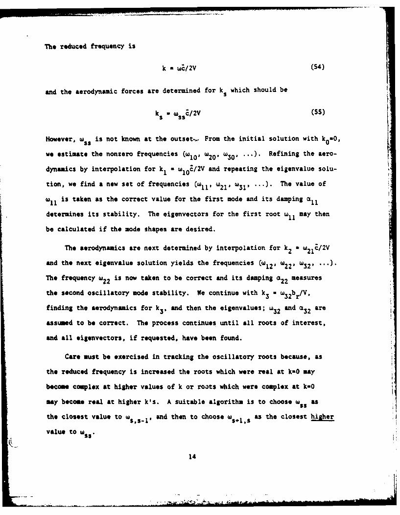
The reduced frequency is
k a wc/SV (54)
and the aerodynamic forces are determined for k s which should be
ks - wssE/2V (s)
However, w is not known at the outset- From the initial solution with k0 no,
we estimate the nonzero frequencies (w10, W20 1 W30 1 -"). Refining the aero-
dynamics by interpolation for k1 - W10E/2V and repeating the eigenvalue solu-
tion, we find a new sat of frequencies (w1 1, W2 1 W311 "") The value of
W 11is taken as the correct value for the first mode and its damping all
determines its stability. The eigenvectors for the first root w may then
be calculated if the mode shapes are desired.
The aerodynamics are next determined by interpolation for k2 a W2 1E/2V
and the next eigenvalue solution yields the frequencies (w12 1 w2 2 ' '32 ' "" )"
The frequency w2 2 is now taken to be correct and its damping a22 measures
the second oscillatory mode stability. We continue with k3 M W3 2 br/V,
finding the aerodynamics for k3 , and then the eigenvalues; w3 2 and a are
assumed to be correct. The process continues until all roots of interest,
and all eigenvectors, if requested, have been found.
Care must be exercised in tracking the oscillatory roots because, as
the reduced frequency is increased the roots which were real at k-O may
become complex at higher values of k or roots which were complex at k-O
may become real at higher k's. A suitable algorithm is to choose wss as
the closest value to w s 1,s- and then to choose w s+ls as the closest hither
value to W
14

Linear Spline Interpolation of Aerodynamic Terms
In the modal matrix equations of motion, twelve of the partitions
depend on the aerodynamic influence coefficients (AIC's) which are functions
of the reduced frequency k. As the reduced frequency changes when the roots
are tracked in the frequency lining up process, the AIC's will change and
interpolation on k is necessary. It is computationally simpler to inter-
polate the partitions rather than the AIC's. Two of the partitions depend
on structural parameters also but these are independent of k and can be
carried along in the interpolation. A linear spline is chosen for the
interpolation because it offers cubic accuracy and continuity throughout
the regions of interpolation and extrapolation.
A linear spline is a mathematical device for interpolating for a
function y(x) for all points x, when y is known for a discrete set of
points, Yi " y(xi). The spline passes through all of the known points.
The "thematical spline takes its name from the plastic spline used by
draftsmen for drawing curves through specified points. If the plastic
spline may be regarded as a uniform beam, the linear spline representing
it mathematically is a solution to the uniform beam differential equation.
The following derivation for the linear spline is taken from Ref. 10, App. E,
by R. L. Harder.
We wish to determine the deflection curve of a continuous beam over
aultiple supports. Consider the fundamental solution to the deflection
equation
El dx4- w (S6a)
a 0 (S6b)
is
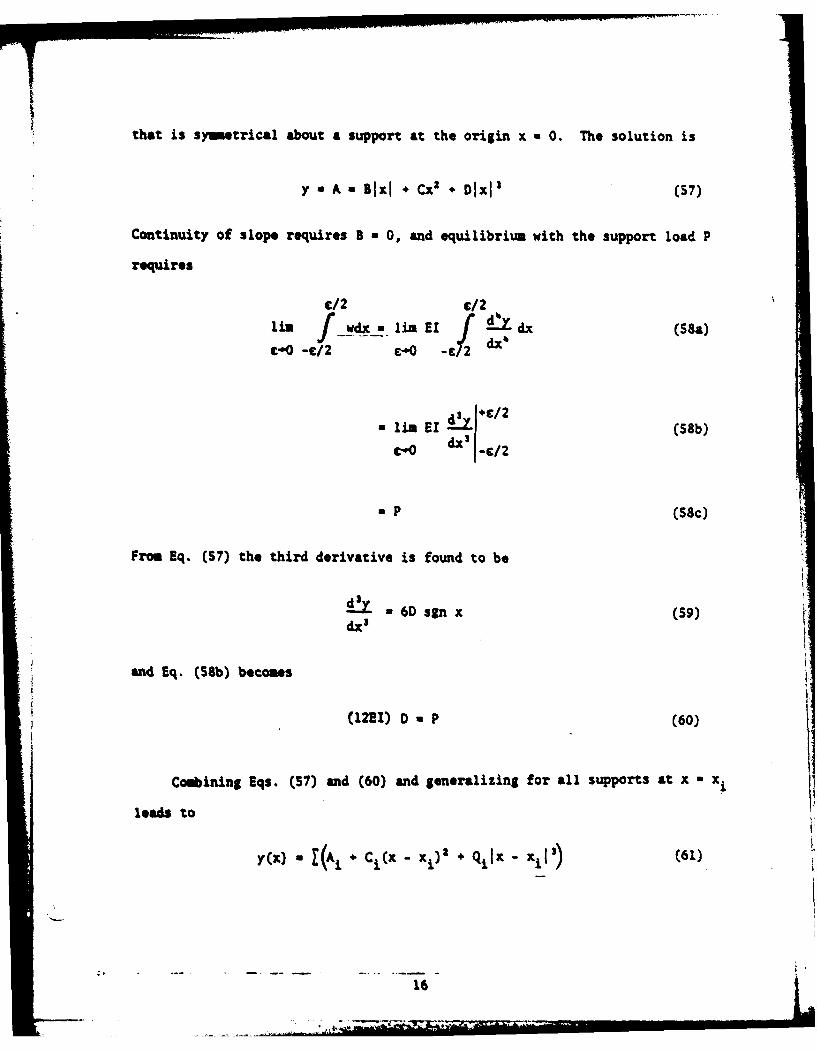
that is symetrical about a support at the origin x O. The solution is
y An ak *j Cx2 + Dlxi' (S7)
Continuity of slope requires B 0, and equilibrium with the support load P
requires
c/2 c/2li" f/ dx- Iii EI AIX dx )
c -0 - .£ 0 - I d x(
a lim El !y +c/2 (S8b)_-0 dx3 I-/2
a P (S8c)
From Eq. (S7) the third derivative is found to be
!9X 6D sgn x (59)dx3
and Eq. (S8b) becomes
(12 1) D p (60)
Combining Eqs. (57) and (60) and generalizing for all supports at x a x
leads to
y Ix) a + C i(x -x) QiIx -xi') (61)
16

where Qi Pi/12EI. At a large distance from the supports, the deflection
curve should be linear. For large x " -, Eq. (61) behaves like
y(x) - x 13&n x (Ci " 3xisXgn x) o(x) (62)
and the required linear behavior necessitates
Q - 0 (63)
C - 0 (64)
qixi o. 6(6S)
Equations (63) and (65) are equilibrium equations, and Eq. (64) permits
writing
*(Aj + C (X - xi)) ao + ax (66)
in Eq. (61), where a0 and aI are new constants, so that Eq. (61) becomes
y(x) - ao + alx *+ Qi x - xiV (67)
In the case where the spline is symmetrical about the origin, as is
the case for the AICs (Cs(k)] and [hh(k)] which are symmetrical functions of
the reduced frequency k, we may use the method of images and Eq. (67) becomes
y(X) - &0 + I q(X - I!' + Ix * xil') (68)
and only Eq. (63) needs to be satisfied in addition to Eq. (68). The matrix
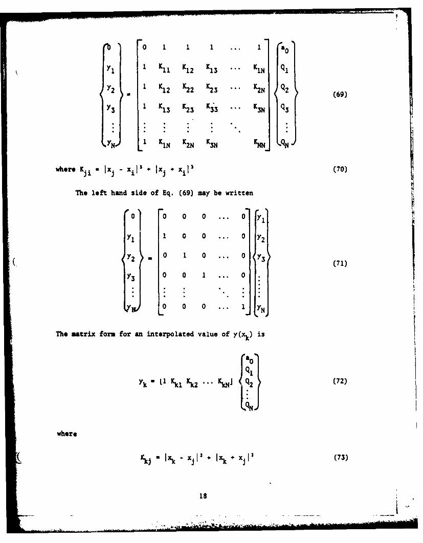
form for Eqs. (63) and (68) in terms of the specified values of y(xj) is
17
mV
0 1 ... I a
I K, K12 K 13 K1N qi
2 K12 K22 K23 ... K2N q2 (69)
YS1 K13 K2 3 K 33 K K3N (Q3
1 K1N K2N K 3N NN N
where Kji Ix - xil * Ixi + xil 3 (70)
The left hand side of Eq. (69) may be written
o 0 o ... o ,
YI1 0 0 ... 0 Y
2Y 0 1 0 . . 0 Y3(71)
0 0 1 ... 0
0 0 0 ... 1
17 NThe matrix form for an interpolated value of y(xk) is
ao0
Yk Ll Kk1 Kk2 ... KN & Q (72)
where
r *k j " x k x ' + I . x 1 3 (7 3 )
18
.,. . . . . .-m
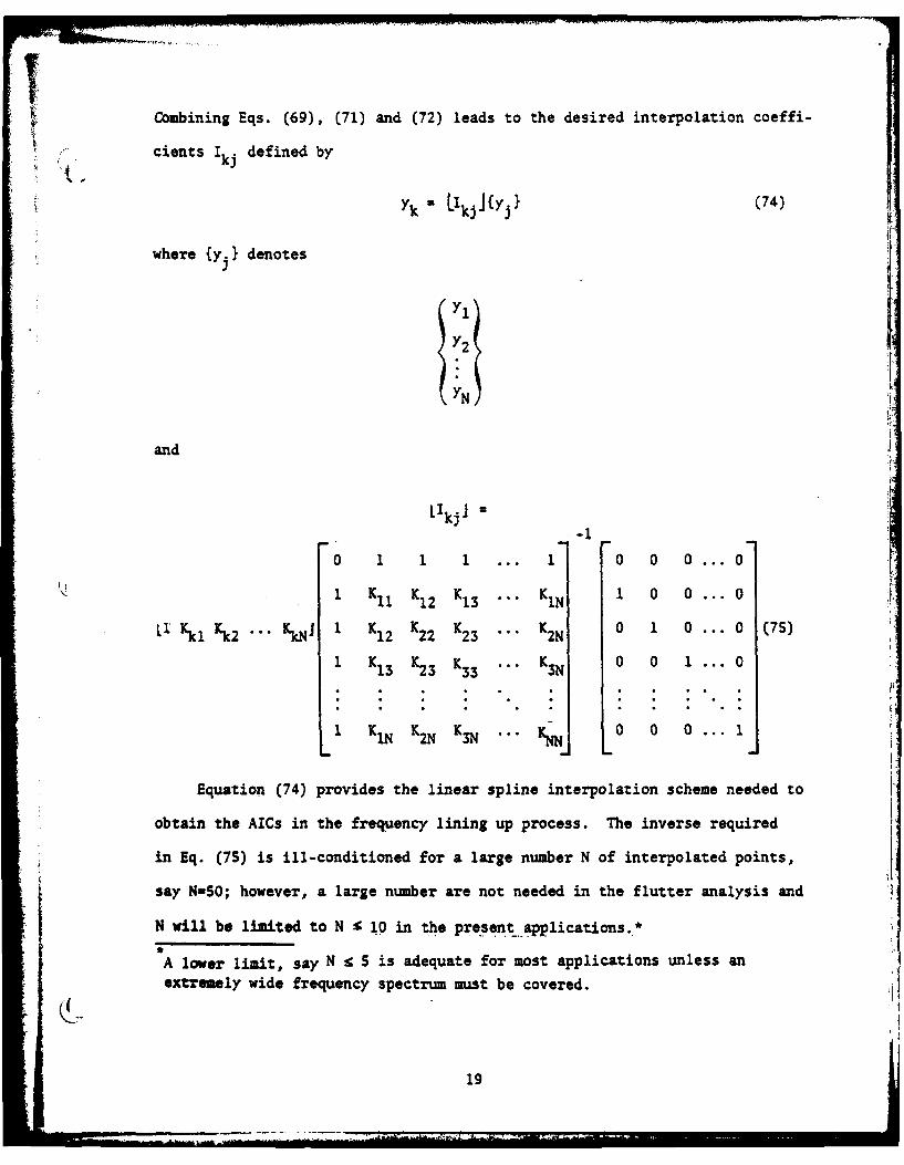
Combining Eqs. (69), (71) and (72) leads to the desired interpolation coeffi-
cients I defined by
(74)~~Yk "Lkjl{Yj} C4
where {yj} denotes
Yl
' Y2
and
L'kjl =-l
0 1 1 1 ... 1 0 0 0 ... 0
1 1 K11 KI2 K13 ... KIN 1 0 0 ... 0
Ll Kkl Kk2 ... KNJ 1K 12 K22 K23 ... K2N 01 0... 0 (75)
1 KI3 K23 K K . . K 0 0 1 ... 0
1 KNK 2N K3N .. 0 0 0 ... 1
Equation (74) provides the linear spline interpolation scheme needed to
obtain the AICs in the frequency lining up process. The inverse required
in Eq. (7S) is ill-conditioned for a large number N of interpolated points,
say N=SO; however, a large number are not needed in the flutter analysis and
N will be limited to N £ 10 in the present.applications.*
A lower limit, say N - 5 is adequate for most applications unless anextremely wide frequency spectrum must be covered.
19
SECTION III
AERO-SERVO-ELASTIC STABILITY ANALYSIS PROGRAM: MPASES
Program Description
MPASES is a general purpose digital computer program for the analysis of
the closed-loop stability problem. This program, which is a modification of
PASES (Ref. 1), formulates the problem by combining a classical method for
determining servomechanism system stability with the more realistic British
method of flutter analysis in lieu of the American method used in PASES. With
the input of an arbitrary number of elastic degrees of freedom, aerodynamic
influence coefficients and the control system description, the stability
of a missile or aircraft configuration as an aero-servo-elastic system can
be investigated. When no aerodynamics are involved, the servo-elastic system
stability can be determined.
Dynamic storage allocation utilized throughout MPASES provides the
most efficient U3e of core storage through the variable dimensioning of
all arrays. Because the program is based on the theory that permits the
inclusion of the aerodynamic forces as spring and damper terms in the
equations of motion rather than as complex inertial terms, only real
matrices are used in the eigenvalue solution. This makes for additional
economy in computer usage.
MPASES uses the method of revising the aerodynamics by lining up the
frequencies and performing the spline interpolation of the aerodynamic
terms necessary in the iterative eigenvalue solution. This process is
repeated until the required number of modes and eigenvectors are obtained
for a particular velocity. Moreover, if the analysis Mach number (velocity
determining factor) differs from the AIC Mach numbers by more than a speci-
fied 'deviation' value (input by the submitter), spline interpolation of the
20
C77_
aerodynamic forces is performed also. In this case, the program interpolates
for Mach number before the reduced frequency interpolation for each mode is
carried out.
The variables in the stability analysis of an aero-servo-elastic system
are servo-gains, velocities (through Mach number and speed of sound input)
and altitude (air density input). An option is provided to vary the gain
of a single servo component or control surface with the density and Mach
number held constant. When this option is executed, the coefficients of the
output of the desired servo element or control surface are divided by the
gain factor, K. This method facilitates programming, since there may be
more than one input.
Since dynamic dimensioning is used, the program limitations are minimal.
Stability results can be obtained for up to five (S) altitudes and for each
density, as many as ten (10) different velocities can be analyzed. In
addition, twenty-five (25) gain variations are permitted. The number of AIC
matrices that can be input is limited to ten (10) reduced frequencies for each
of five (5) Mach numbers. There are no size restrictions for any of the other
parmters existing in the progpam.
The total number of memory units (words or bytes) required to execute
MPASES is completely dependent upon input. The size of the program is
reflected in the length of the blank common block found in the 'MAIN'
section of the program. The length can readily be altered to accomodate
different analyses. Likewise, dimensions of the arrays limiting the pro-
gram as stipulated above can be changed to the desired size.
21
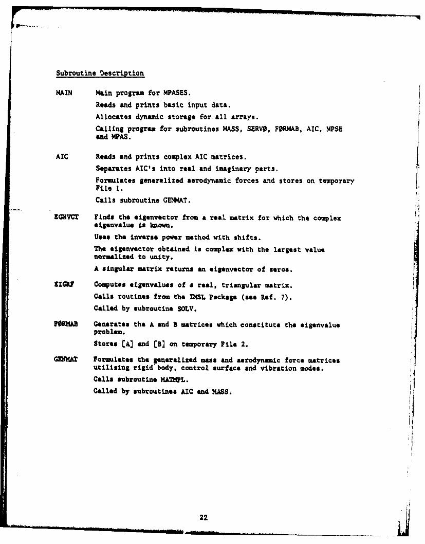
Subroutine Description
MAIN Main program for MPASES.
Reads and prints basic input data.
Allocates dynamic storage for all arrays.
Calling program for subroutines MASS, SERVO, FORMAB, AIC, MPSEand MPAS.
AIC Reads and prints complex AIC matrices.
Separates AIC's into real and imaginary parts.
Formulates generalized aerodynamic forces and stores on temporaryFile I.
Calls subroutine GENMAT.
ZGIVCT Finds the eigenvoctor from a real matrix for which the complexeigenvalue is known.
Uses the inverse power method with shifts.
The eigenvoctor obtained is complex with the largest valuenormalized to unity.
A singular matrix returns an esigenvector of zeros.
ZIGRF Computes eigenvalues of a real, triangular matrix.
Calls routines from the IMSL Package (see Ref. 7).
Called by subroutine SOLV.
FPIKA3 Generates the A and B matrices which constitute the sigenvalueproblem.Stores A and (B] on temporary File 2.
GMT= Formulates the pueralized mass and aerodynamic force matricesutilizing rigid body, control surface and vibration modes.Calls subroutine MKZAML.
Called by subroutines AIC and MASS. 4
22j
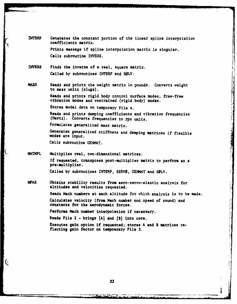
-ITERP Generates the constant portion of the linear spline interpolation
coefficients matrix.
Prints message if spline interpolation matrix is singular.
Calls subroutine INVERS.
INVERS Finds the inverse of a real, square matrix.
Called by subroutines INTERP and S0LV.
KASS Reads and prints the weight matrix in pounds. Converts weight
to mass units (slugs).Reads and prints rigid body control surface modes, free-freevibration modes and restrained (rigid body) modes.
Stores modal data on temporary File 4.
Reads and prints damping coefficients and vibration frequencies(Hertz). Converts frequencies to rps units.
Formulates generalized mass matrix.
Generates generalized stiffness and damping matrices if flexiblemodes are input.
Calls subroutine GENMAT.
MATMPL Multiplies real, two-dimensional matrices.
If requested, transposes post-multiplier matrix to perform as apre-multiplier.
Called by subroutines INTERP, SERVO, GENMAT and SOLV.
MPAS Obtains stability results from aero-servo-elastic analysis for
altitudes and velocities requested.
Reads Mach numbers at each altitude for which analysis is to be made.
Calculates velocity (from Mach number and speed of sound) andconstants for the aerodynamic forces.
Performs Mach number interpolation if necessary.
Reads File 2 - brings (A] and [B] into core.
Executes gain option if requested; stores A and B matrices re-flecting gain factor on tempoerary File 3.
13
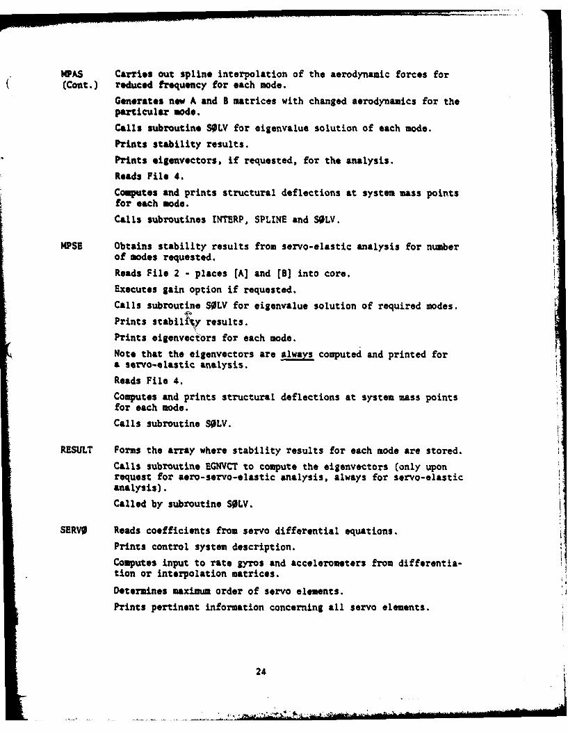
PAS Carries out spline interpolation of the aerodynamic forces for(Cont.) reduced frequency for each mode.
Generates new A and B matrices with changed aerodynamics for theparticular mode.Calls subroutine S0LV for eigenvalue solution of each mode.
Prints stability results.
Prints eigenvectors, if requested, for the analysis.
Reads File 4.
Computes and prints structural deflections at system mass pointsfor each mode.
Calls subroutines INTERP, SPLINE and SOLV.
4PSE Obtains stability results from servo-elastic analysis for number
of modes requested.
Reads File 2 - places [A] and [B] into core.
Executes gain option if requested.
Calls subroutine SOLV for eigenvalue solution of required modes.
Prints stabil~y results.
Prints eigenvectors for each mode.
Note that the eigenvectors are always computed and printed fora servo-elastic analysis.
Reads File 4.
Computes and prints structural deflections at system mass pointsfor each mode.
Calls subroutine S0LV.
RESULT Forms the array where stability results for each mode are stored.
Calls subroutine EGNYCT to compute the eigenvectors (only uponrequest for aero-servo-elastic analysis, always for servo-elasticanalysis).
Called by subroutine S0LV.
SERVO Reads coefficients from servo differential equations.
Prints control system description.
Computes input to rate gyros and accelerometers from differentia-tion or interpolation matrices.
Determines maximum order of servo elements.
Prints pertinent information concerning all servo elements.
24
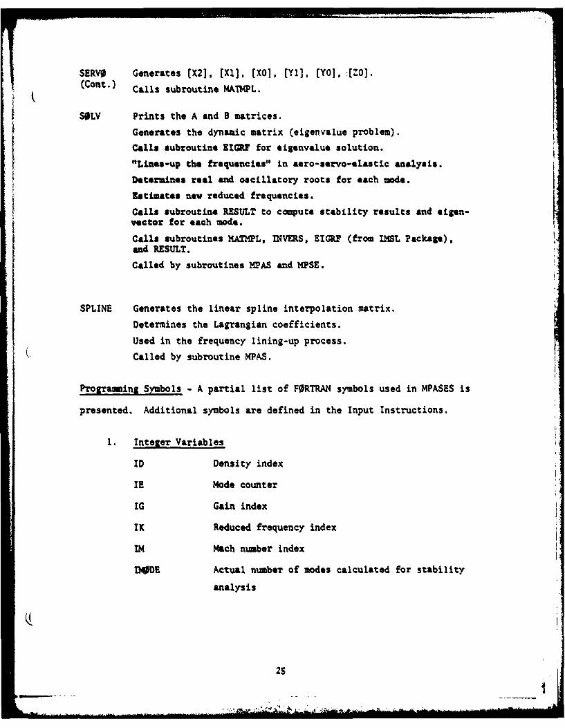
SERVO Generates (X2], [Xl], [Xo1, [Yl], [Yo, :[Zo].(Cant.) Calls subroutine MAThPL.
SOLV Prints the A and B matrices.
Generates the dynamic matrix (eigenvalue problem).
Calls subroutine EIGF for sigenvalue solution.
"LLnes-up the frequencies" in aero-servo-elastic analysis.
Determines real and oscillatory roots for each mode.
Estimates new reduced frequencies.
Calls subroutine RESULT to compute stability results and sigen-vector for each mode.
Calls subroutines MATMPL, INVERS, EIGRF (from IMSL Package),and RESULT.
Called by subroutines 11PAS and 11PSE.
SPLINE Generates the linear spline interpolation matrix.
Determines the Lagrangian coefficients.
Used in the frequency lining-up process.
( Called by subroutine MPAS.
Programming Symbols - A partial list of FORTRAN symbols used in HPASES is
presented. Additional symbols are defined in the Input Instructions.
1. Integer Variables
ID Density index
IE Mode counter
IG Gain index
IK Reduced frequency index
IM Mach number index
IMODE Actual number of modes calculated for stability
analysis
2SI
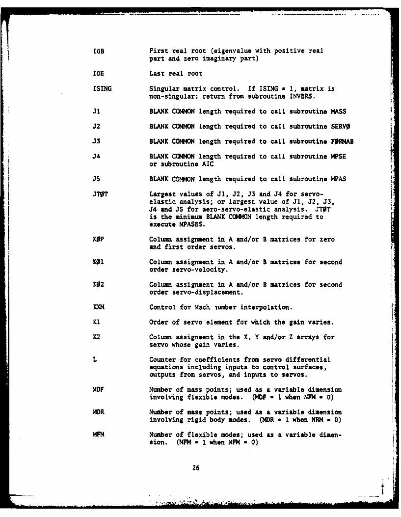
L0B First real root (eigenvalue with positive real
part and zero imaginary part)
IOE Last real root
ISING Singular matrix control. If ISING = 1, matrix isnon-singular; return from subroutine INVERS.
Ji BLANK COMMON length required to call subroutine MASS
J2 BLANK COMMON length required to call subroutine SERVO
J3 BLANK COMMON length required to call subroutine FORMAB
J4 BLANK COMMON length required to call subroutine MPSEor subroutine AIC
J5 BLANK COMMON length required to call subroutine MPAS
JT0T Largest values of Jl, J2, J3 and J4 for servo-elastic analysis; or largest value of Jl, J2, J3,J4 and JS for aero-servo-elastic analysis. JT0Tis the minimum BLANK COMMON length required toexecute MPASES.
KOP Column assignment in A and/or B matrices for zeroand first order servos.
KOI Column assignment in A and/or B matrices for secondorder servo-velocity.
K02 Column assignment in A and/or B matrices for secondorder servo-displacement.
KX Control for Mach aumber interpolation.
K1 Order of servo element for which the gain varies.
K2 Column assignment in the X, Y and/or Z arrays forservo whose gain varies.
L Counter for coefficients from servo differentialequations including inputs to control surfaces,outputs from servos, and inputs to servos.
MDF Number of mass points; used as a variable dimensioninvolving flexible modes. (MDF a 1 when NFM a 0)
MDR Number of mass points; used as a variable dimensioninvolving rigid body modes. (MDR - I when NRM a 0)
MFM Number of flexible modes; used as a variable dimen-sion. (MFM a 1 when NFM 0)
26 4-
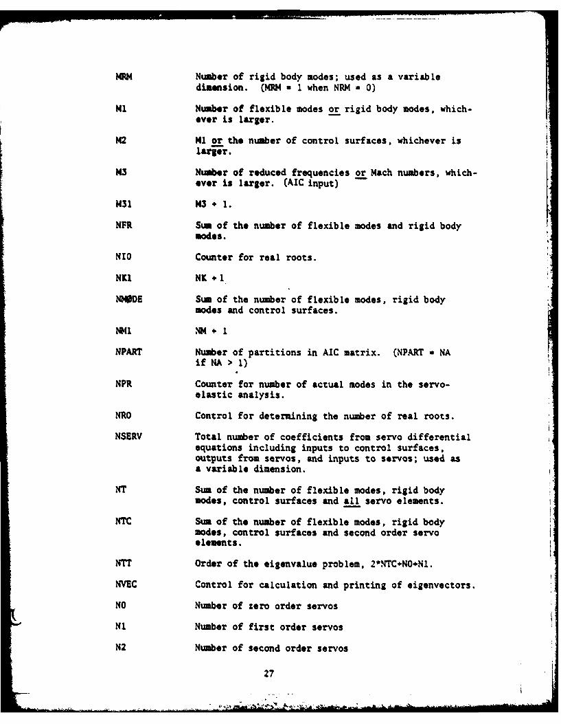
MRM Number of rigid body modes; used as a variabledimension. (MRM a 1 when NRM a 0)
Ml Number of flexible modes or rigid body modes, which-ever is larger.
M2 Ml or the number of control surfaces, whichever islarr.
M3 Number of reduced frequencies or Mach numbers, which-ever is larger. (AIC input)
M31 M3 + 1.
NFR Sum of the number of flexible modes and rigid bodymodes.
NIO Counter for real roots.
NK1 NK + 1
NMODE Sum of the number of flexible modes, rigid bodymodes and control surfaces.
NI NM. I+
NPART Number of partitions in AIC matrix. (NPART a NAif NA > 1)
NPR Counter for number of actual modes in the servo-elastic analysis.
NRO Control for determining the number of real roots.
NSERV Total number of coefficients from servo differentialequations including inputs to control surfaces,outputs from servos, and inputs to servos; used asa variable dimension.
NT Sum of the number of flexible modes, rigid bodymodes, control surfaces and all servo elements.
NTC Sum of the number of flexible modes, rigid bodymodes, control surfaces and second order servoelements.
NTT Order of the eigenvalue problem, 2*NTC+NO+Nl.
NVEC Control for calculation and printing of eigenvectors.
NO Number of zero order servos
N1 Number of first order servos
N2 Number of second order servos
27
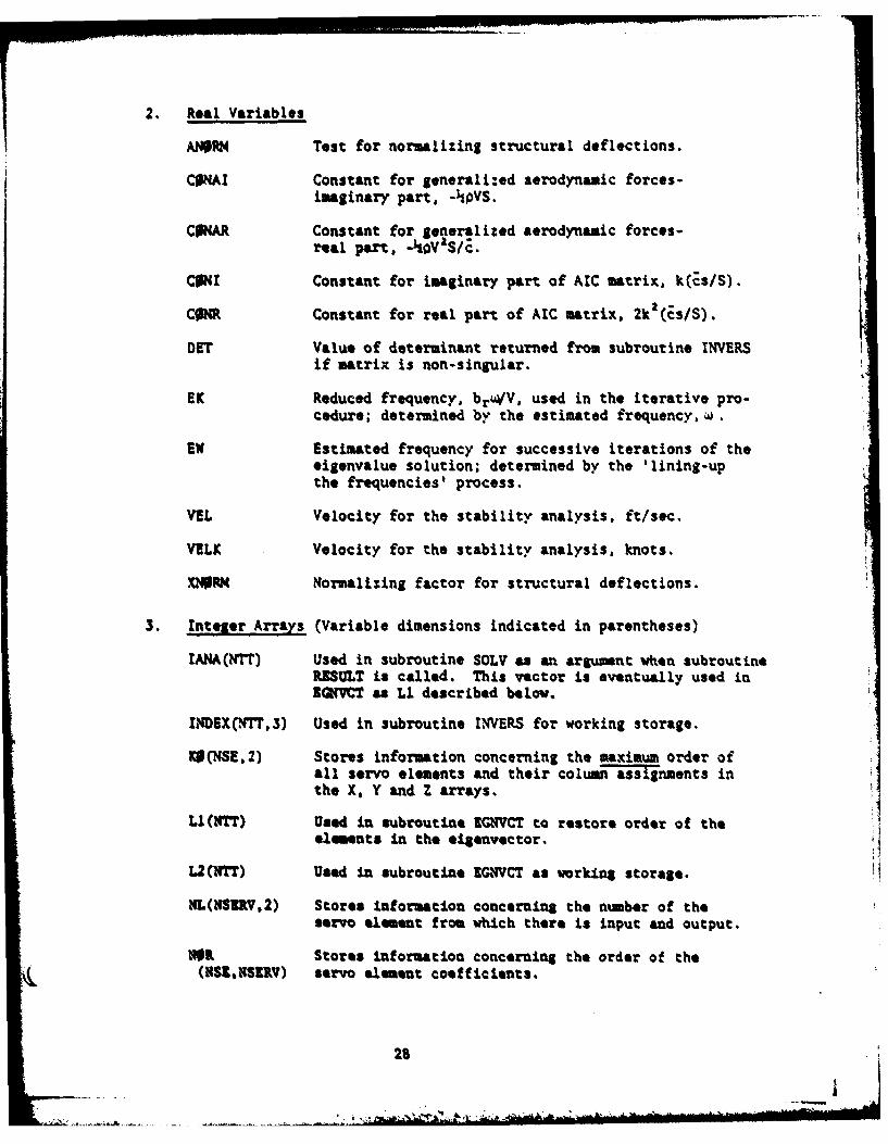
2. Real Variables
ANOPM Test for normalizing structural deflections.
COMAI Constant for generali:ed aerodynamic forces-imaginary part, -pVS.
Cow Constant for generalized aerodynamic forces-real part, - 0Va/S/Z.
CONI Constant for imaginary part of AIC matrix, k(Zs/S). VCONR Constant for real part of AIC matrix, 2k2 (Es/S).
DET Value of determinant returned from subroutine INVERSif matrix is non-singular.
EK Reduced frequency, br4/V, used in the iterative pro-cedure; determined by the estimated frequency, w,
EW Estimated frequency for successive iterations of theeigenvalue solution; determined by the 'lining-upthe frequencies' process.
VEL Velocity for the stability analysis, ft/sec.
VELK Velocity for the stability analysis, knots.
.MNR4 Normalizing factor for structural deflections.
3. Integer Arrays (Variable dimensions indicated in parentheses)
IANA(NTT) Used in subroutine SOLV as an argument when subroutineRESULT is called. This vector is eventually used inZQVT as Li described below.
INDEX(WTF,3) Used in subroutine INVERS for working storage.
KO(NSE,2) Stores information concerning the maximum order ofall servo elements and their column assignments inthe X, Y and Z arrays.
LI(NTT) Used In subroutine EGNVCT to restore order of theelements in the eigenvector.
L2(TT) Used in subroutine ZGCVCT as working storage.
NL(NSUV,2) Stores information concerning the nuber of theservo element from which there is input and output.
NOR Stores information concerning the order of the(NSK,NSnV) servo element coefficients.
28
- a .A_. --
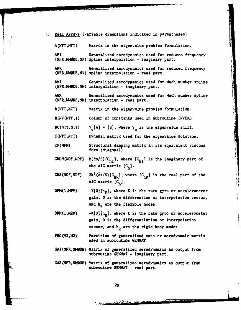
4. Real Arrays (Variable dimensions indicated in parentheses)
A(N r,,Tr) Matrix in the eigenvalue problem formulation.
AFI Generalized aerodynamics used for reduced frequency(NFR,NMODE,NK) spline interpolation - imaginary part.
APR Generalized aerodynamics used for reduced frequency(NFR,tU40DE,NK) spline interpolation - real part.
A I Generalized aerodynamics used for Mach number spline(NPR,NODE,NM) interpolation - imaginary part.
A4R Generalized aerodynamics used for Mach number spline(NFR,NWMDEoNM) interpolation - real part.
B(NTT,NTT) Matrix in the eigenvalue problem formulation.
BINV(,NT,l) Column of constants used in subroutine INVERS.
BC(NT,,YT) YO [A] + [B], where y is the eigenvalue shift.
C(NTT,NTT) Dynamic matrix used for the eigenvalue solution.
CF(FM) Structural damping matrix in its equivalent viscous
form (diagonal)
CHDH(NDF,NDF) k(Es/S)(ChI]. where [C] is the imaginary part of
the AIC matrix [Ch].
CHS(NDF,NDF) 2Y.2(Zs/S) [ChR ] , where [ChR ] is the real part of the
AIC matrix [Chl.
DFM(1,MFM) -K[D][h.]. where K is the rate gyro or accelerometer
gain, D is the differention or interpolation vector,
and hF are the flexible modes.
DRM(I,MR) -K(D][ha], where K is the rate gyro or accelerometer
gain, D is the differentiation or interpolation
vector, and hR are the rigid body modes.
FRC(2,M2) Partition of generalized mass or aerodynamic matrixused in subroutine GENHAT.
GAI(NFR,NM0DE) Matrix of generalized aerodynamics as output fromsubroutine GENMAT - imaginary part.
( GAR(NFRNMHDE) Matrix of generalized aerodynamics as output fromsubroutine GEAT - real part.
29
'
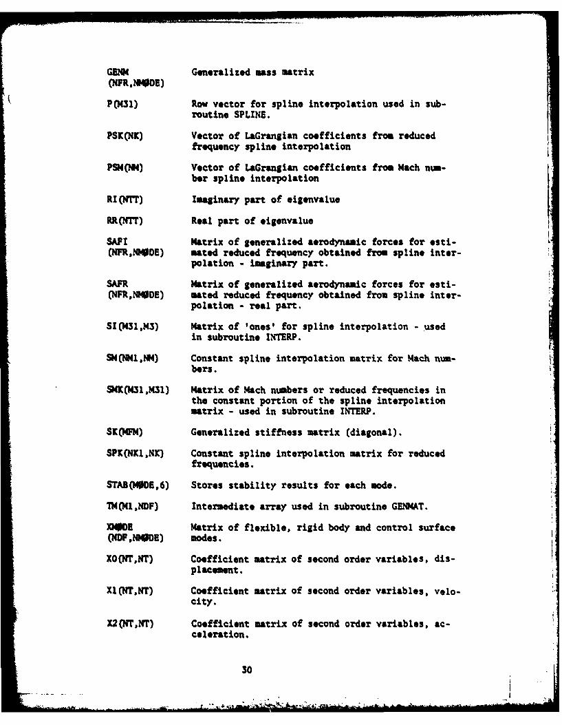
GENM Generalized Mass matrix(NFR.MPOE)
P(M31) Row vector for spline interpolation used in sub-routine SPLINE.
PSX(NK) Vector of LaGrangian coefficients from reducedfrequency spline interpolation
PSM(N) Vector of LaGrangian coefficients from Mach num-ber spline interpolation
RI(NrT) Imaginary part of eigenvalue
RR(NrT) Real part of eigenvalue
SAPI Matrix of generalized aerodynamic forces for esti-(NFR,NDE) mated reduced frequency obtained from spline inter-
polation - imaginary part.
SAFR Matrix of generalized aerodynamic forces for esti-(NFRMPDE) mated reduced frequency obtained from spline inter-
polation - real part.
SI(M31,M3) Matrix of 'ones' for spline interpolation - usedin subroutine INTERP.
SM(NM1 ,4) Constant spline interpolation matrix for Mach num-bers.
SNK431,M31) Matrix of Mach numbers or reduced frequencies inthe constant portion of the spline interpolationmatrix - used in subroutine INTERP.
SK(MFM) Generalized stiffness matrix (diagonal).
SPK(NKlNK) Constant spline interpolation matrix for reducedfrequencies.
STAB(MODE,6) Stores stability results for each mode.
Th(41 ,NDF) Intermediate array used in subroutine GENMAT.
XMO)E Matrix of flexible, rigid body and control surface(NDF,NMPDE) modes.
XO(fN,NT) Coefficient matrix of second order variables, dis-placement.
XI(NTNT) Coefficient matrix of second order variables, velo-city.
X2(NT,NT) Coefficient matrix of second order variables, ac-celeration.
30
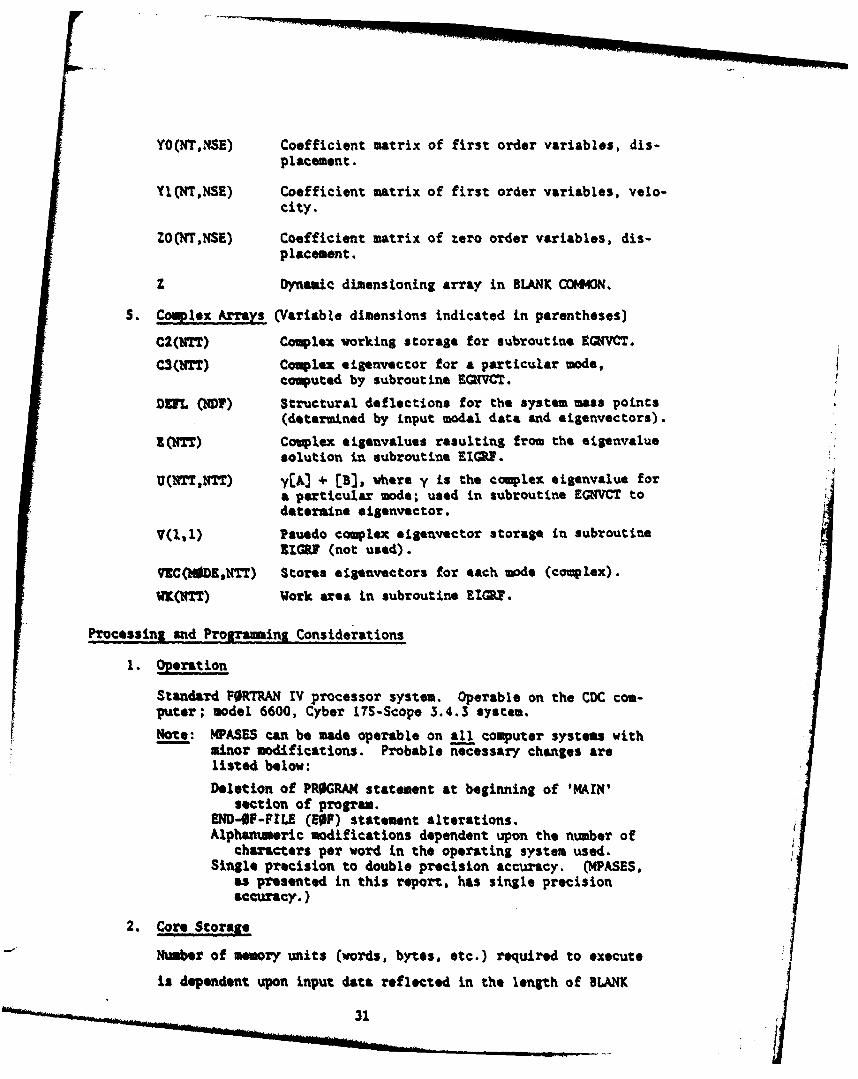
YO(NTNSE) Coefficient matrix of first order variables, dis-placement.
YI(NT,NSE) Coefficient matrix of first order variables, velo-city.
ZO(NT,NSE) Coefficient matrix of zero order variables, dis-placement.
z Dynamic dimensioning array in BLANK COMMON.
5. Complex Arrays (Variable dimensions indicated in parentheses)
C2(='T) Complex working storage for subroutine EQ(VCT.
C3(bT) Complex eigenvector for a particular mode,computed by subroutine EGHVCT.
DUL (NDF) Structural deflections for the system mass points(detatrined by input modal data and eigenvectors).
(NTT) Couplex eigenvalues resulting from the aigenvaluesolution in subroutine EIGRI.
U(4TT,NTT) y[A] + [B], where y is the complex eigenvalue fora particular mode; used in subroutine EGNVCT todetermine oiSenvector.
V(ll) Psuedo complex $igenvector storage in subroutine11GZIG (not used).
VC(MODRONTT) Stores elganvectors for each mode (complex).
VV (KTT) Work area in subroutine EIGUP.
Procossing and Prognaing Considerations
1. Operation
Standard FORTRAN IV processor system. Operable on the CDC com-puter; model 6600, Cyber 11S-Scope 3.4.3 system.
Fote: MPASES can be made operable on all computer systems withminor modifications. Probable necessary changes arelisted below:
Deletion of PROGRA4 statement at beginning of 'MAIN'section of program.
END-iF-FILE (EO ) statement alterations.Alphanumeric modifications dependent upon the number of
characters per word in the operating system used.Single precision to double precision accuracy. (IPASES,
as presented in this report, has single precisionaccuracy.)
2. Core Storage
Number of memory units (words, bytes, etc.) required to execute
is dependent upon input data reflected in the length of BLANK
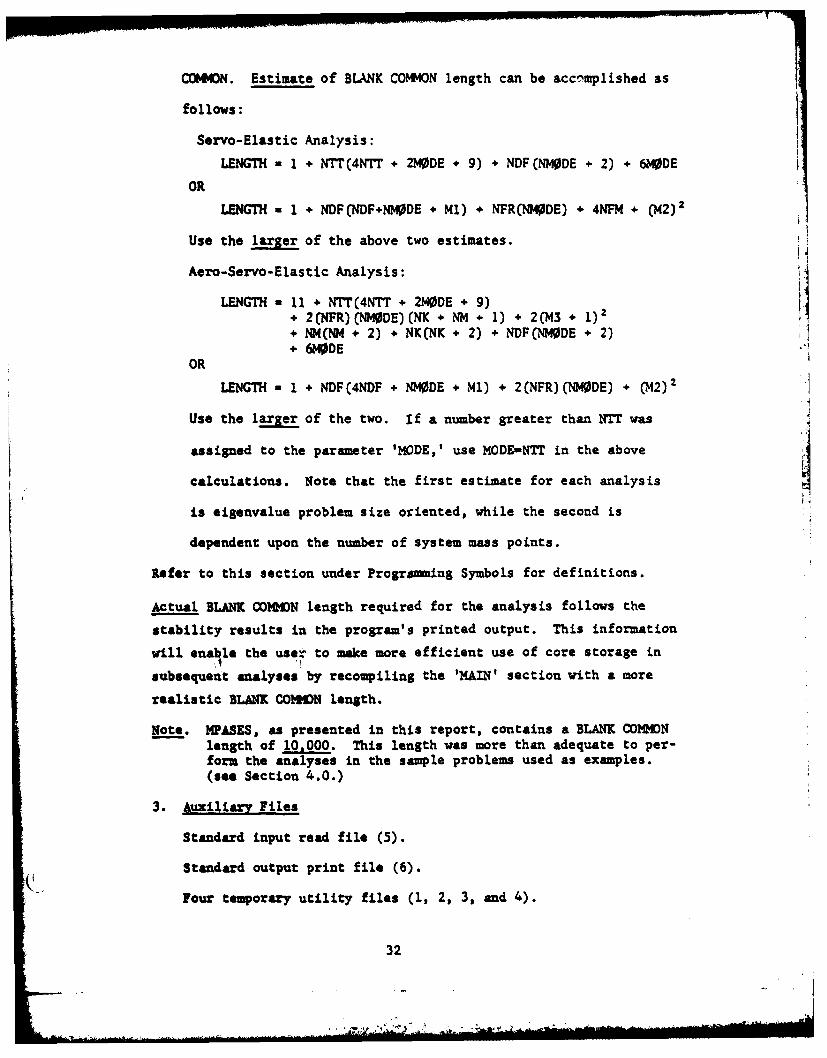
COMMON. Estimate of BLANK COMMON length can be accnmplished as
follows:
Servo-Elastic Analysis:
LENGTH = 1 + NTT(4NTT + 2MDE + 9) + NDFCNMODE + 2) + 6M0DE
OR
LENGTH. 1 + NDF(NDF+NMODE + Ml) + NFR(NI40DE) + 4NF1 + (M2)2t
Use the larger of the above two estimates.
Aero-Servo-Elastic Analysis:
LENGTH - 11 + NTTC4NTT + 2MDE * 9) I" 2CNFR)(NMODE)(NK + NM + 1) * 2(M43 1)2" NH(NM + 2) + NK(NK + 2) + NDF(NMODE + 2)" DE
OR
LENGTH a 1 + NDF(4NDF + NIMDE + Ml) + 2(NFR)(NM0DE) + (,[2)2
Use the larger of the two. If a number greater than NTT was
assigned to the parameter 'MODE,' use MODE-NTT in the above
calculations. Note that the first estimate for each analysis
is eigenvalue problem size oriented, while the second is
dependent upon the number of system mass points.
Refer to this section under Progrening Symbols for definitions.
Actual BLANK COMDN length required for the analysis follows the
stability results in the program's printed output. This information
will enable the user to make more efficient use of core storage in
subsequent analyses by recompiling the 'MAIN' section with a more
realistic BLANK COHMN length.
Note. MPASES, as presented in this report, contains a BLANK COONlength of 10,000. This length was more than adequate to per-form the analyses in the sample problems used as examples.(see Section 4.0.)
3. Auxiliary Files
Standard input read file (5).
Standard output print file (6).
Four temporary utility files (1, 2, 3, and 4).
32i S
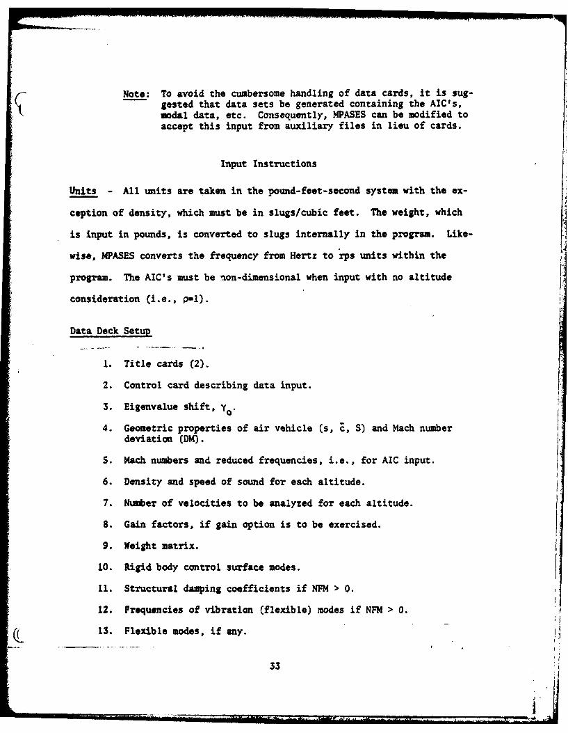
Note: To avoid the cumbersome handling of data cards, it is sug-gested that data sets be generated containing the AIC's,modal data, etc. Consequently, MPASES can be modified toaccept this input from auxiliary files in lieu of cards.
Input Instructions
Units - All units are taken in the pound-feet-second system with the ex-
ception of density, which must be in slugs/cubic feet. The weight, which
is input in pounds, is converted to slugs internally in the program. Like-
wise, MPASES converts the frequency from Hertz to rps units within the
program. The AIC's must be non-dimensional when input with no altitude
consideration (i.e., p-1).
Data Deck Setup
1. Title cards (2).
2. Control card describing data input.
3. Eigenvalue shift, y0
4. Geometric properties of air vehicle (s, , S) and Mach number
deviation (DM).
S. Mach numbers and reduced frequencies, i.e., for AIC input.
6. Density and speed of sound for each altitude.
7. Number of velocities to be analyzed for each altitude.
8. Gain factors, if gain option is to be exercised.
9. Weight matrix.
10. Rigid body control surface modes.
I1. Structural damping coefficients if NFM > 0.
12. Frequencies of vibration (flexible) modes if NFM > 0.
13. Flexible modes, if any.
33
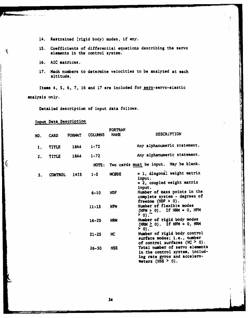
14. Restrained (rigid body) modes, if any.
IS. Coefficients of differential equations describing the servo
elements in the control system.
16. AIC matrices.
17. Mach numbers to determine velocities to be analyzed at eachaltitude.
Items 4, 5, 6, 7, 16 and 17 are included for aero-servo-elastic
analysis only.
Detailed description of input data follows.
Input Data Description
FORTRANNO. CARD FORMAT COLUMNS NAWE DESCRIPTION
1. TITLE 18A4 1-72 Any alphanumeric statement.
2. TITLE 15A4 1-72 Any alphanumeric statement.
NOTE: Two cards must be input. May be blank.
3. CONTROL 1415 1-5 MCODE = 1, diagonal weight matrixinput.a 2, coupled weight matrix
; input.
6-10 NDF Number of mass points in thecomplete system - degrees offreedom CNDF > 0).
11-1S NFM Number of flexible modes(NFM > 0). If NRM a 0, NFM> 0).-
16-20 NRI Number of rigid body modes(NRI42 0). if NFM a 0, NRM> 0).
21-25 NC Number of rigid body controlsurface modes; i.e., numberof control surfaces (NC > 0).
26-30 NSE Total number of servo elements
in the control system, includ-ing rate gyros and accelero-meters (NSE > 0).
34
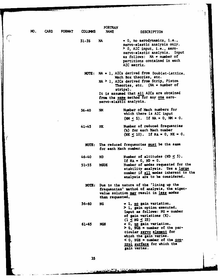
FORTRANNO. CARD FORMAT COLUMNS 1AM DESCRIPTION
31-3S HA 0 0, no aerodynamics, i.e.,servo-elastic analysis only.> 0, AIC input, i.e., aero-servo-elastic analysis. Inputas follows: NA w number ofpartitions contained in eachAIC matrix.
NOTE: NA a 1, AICs derived from Doublet -Lattice,Mach Box theories, etc.
NA > 1, AICs derived from Strip, PistonTheories, etc. (NA a number ofstrips).
It is assumed that all AICs are obtainedfrom the same methoTor any one aero-servo-ela stc analysis.
36-40 NM Number of Mach numbers for
which there is AIC input
(NM<5). IfNA- , NM- .
41-45 NK Number of reduced frequencies(k) for each Mach number
_<(NKl10). If NA-0, NK-0.
NOTE: The reduced frequencies must be the samefor each Mach number.
46-40 ND Number of altitudes (ND < 5).if NA - 0, ND - 0.
51-55 MODE Number of modes requested for thestability analysis. Use a largenumber if all modes inherent to theanalysis are to be1 consi.dered.
NOTE: Due to the nature of the 'lining up thefrequencies' method of analysis, the eiger-value solution may result in less modesthan requested.
56-60 NG - 1, go lain variation.> 1, gain option executed.Input as follow: NG a numberof gain variations (K).(1 5 NG _5 25)
61-65 NGB - 0, no gain variation.> 0, NGB - number of the par-ticular servo element forwhich the gain varies.< 0, NGS - number of the con-trol surface for which thegain varies.
35
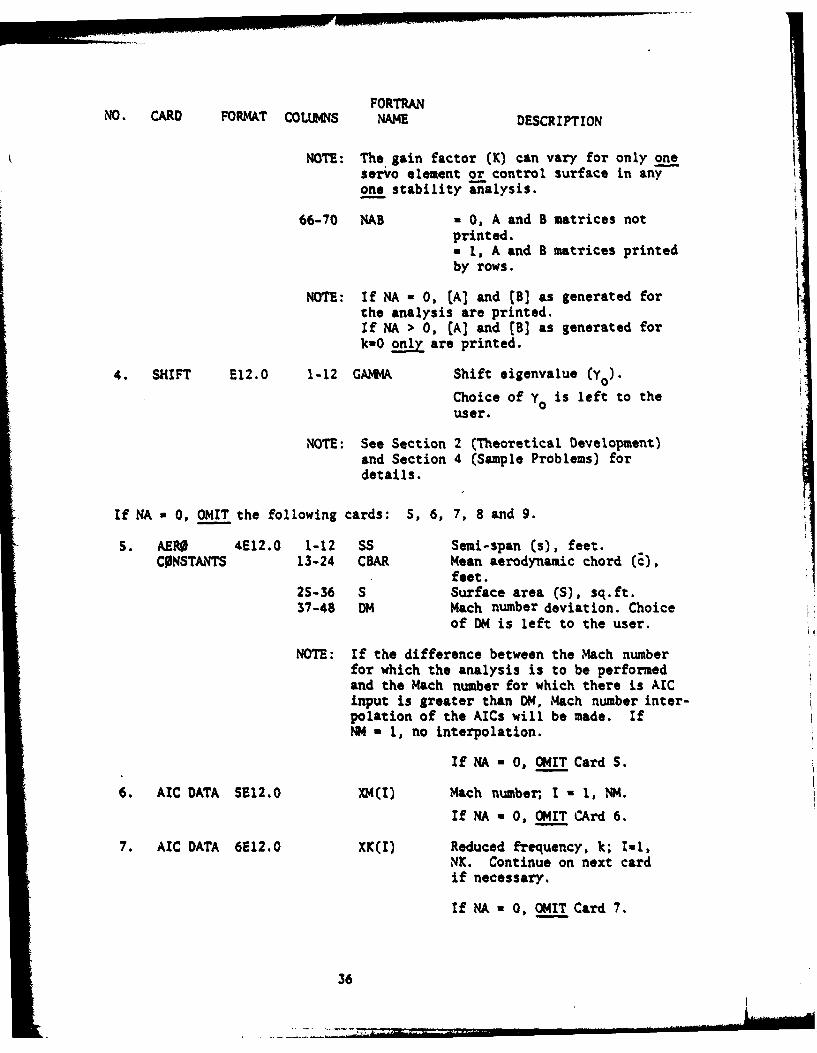
FORTRANNO. CARD FORMAT COLUMNS NAME DESCRIPTION
NOTE: The gain factor (K) can vary for only oneservo element or control surface in anyone stability a7nalysis.
66-70 NAB 0 0, A and B matrices notprinted.aI, A and B matrices printedby rows.
NOTE: If NA - 0, (A] and [B] as generated forthe analysis are printed.If NA > 0, (A] and (B] as generated fork-0 only are printed.
4. SHIFT E12.0 1-12 GA4A Shift eigenvalue (yo).
Choice of Y is left to theuser.
NOTE: See Section 2 (Theoretical Development)and Section 4 (Sample Problems) fordetails.
If NA * 0, OMIT the following cards: 5, 6, 7, 8 and 9.
S. AERO 4E12.0 1-12 SS Semi-span (s), feet.CONSTANTS 13-24 CBAR Mean aerodynamic chord (E),
feet.25-36 S Surface area (S), sq.ft.37-48 DM Mach number deviation. Choice
of DM is left to the user.
NOTE: If the difference between the Mach numberfor which the analysis is to be performedand the Mach number for which there is AICinput is greater than DN, Mach number inter-polation of the AICs will be made. IfNM - 1, no interpolation.
If NA = 0, OMIT Card S.
6. AIC DATA 5E12.0 XM(I) Mach number, I - 1, NM.
If NA a 0, OMIT CArd 6.
7. AIC DATA 6E12.0 XK(I) Reduced frequency, k; Il,NK. Continue on next cardif necessary.
If NA a 0, OMIT Card 7.
36

FORTRANNO. CARD FORMAT COLUMNS NAME DESCRIPTION
S. AER0 DATA 6E12.0 1-12 DENS(l) Air density, P , associatedwith the first altitude atwhich the analysis is to bemade; slugs/cu.ft.
13-24 S0S(l) Speed of sound associatedwith the first altitude;ft/sec.
2S-36 DENS(2) Density for second altitude.37-48 S0S(2) Speed of sound for second
altitude.
DENS(I), SOS(I); 1-1, ND.Continue on next card ifnecessary.
If NA a 0, OMIT Card 8.
9. AERO DATA SI5 MD(I) Number of velocities (deter-mined by Mach number input -
see Card 26) for each alti-tude; I- 1, ND. (MD 1C 10)
If NA a 0, OMIT Card 9.
10. GAIN 6E12.0 GAIN(I) Gain factor, K. I - 1, NG.
Continue on next card ifnecessary. (NG < 25)
If NGS a 0, OMIT Card 10.
11. WEIGHT 6812.0 WT(I,I) If 4CODE a 1, vector of di-agonal elements of weightmatrix, pounds. I * 1, NDF.Continue on next card ifnecessary.
WT(I,J) If MCODE - 2, elements ofupper triangle of coupledweight matrix, lbs. Inputby row; each row starts ona now card. I a 1, NDF,J - I, NDF.Continue on successive cardsto complete each row.
37
FORTRANNO. CARD FORMAT COLUMNS NAME DESCRIPTION
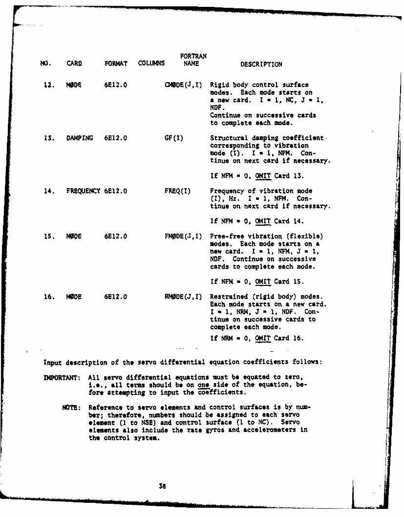
12. MODE 6E12.0 C4DE(J,I) Rigid body control surfacemodes. Each mode starts ona new card. I - 1, NC, J a 1,NDF.Continue on successive cardsto complete each mode.
13. DAMPING 6E12.0 GF(I) Structural damping coefficientcorresponding to vibrationmode (I). I a 1, NW. Con-tinue on next card if necessary.
If NFM a 0, OMIT Card 13.
14. FREQUENCY 6E12.0 FREQ(I) Frequency of vibration mode(I), Hz. I = 1, NFM. Con-tinue on next card if necessary.
If NFM a 0, OMIT Card 14.
15. MODE 6E12.0 FM0DE(J,I) Free-free vibration (flexible)modes. Each mode starts on anew card. I - 1, NFM, J a 1,NOF. Continue on successivecards to complete each mode.
If NFM O, OMIT Card IS.
16. MODE 6E12.0 RODE(J,I) Restrained (rigid body) modes.Each mode starts on a new card.I a 1, NRM, J 1, NDF. Con-tinue on successive cards to pcomplete each mode.
IfNRM a O, OMIT Card 16. V
Input description of the servo differential equation coefficients follows:
IMPORTANT: All servo differential equations must be equated to zero,i.e., all terms should be on one side of the equation, be-fore attempting to input the -efficients.
NOTE: Reference to servo elements and control surfaces is by num-ber; therefore, numbers should be assigned to each servoelement (1 to NSE) and control surface (I to NC). Servoelements also include the rate gyros and accelerometers inthe control system.
38

FORTRANNO. CARD FORMAT COLUMNS NAME DESCRIPTION
REPEAT the following cards 17, 18 and 19 for each control surface, i.e.,RE =tnes.
17. Output from Control Surface. FORMAT (3E12.0)
Columns 1-12 XO(I) Zero order coefficient for Control Sur-face (I).
13-24 Xl(I) First order coefficient for Control Sur-face (I).
25-36 X2(I) Second order coefficient for ControlSurface (I).Note: I-I, NC.
18. Input Control Card. FORMAT (IS)
Columns 1-5 INC Number of inputs from servo elements tocontrol surface (W-T.
REPEAT card 19 for input from each servo element to Control Surface (1),., "INC times.
19. Input from Servo Element. FORMAT (21S,2X,3E12.0)
Columns 1-S K Servo element from which there is input. [6-10 No Order of servo element coefficients.13-24 CO Zero order coefficient.25-36 Cl First order coefficient.37-48 C2 Second order coefficient.
If NO a 0, zero order; only CO input.u 1, first order; Cl must be input (CO may be
zero.a 2, second order; C2 must be input (CO and
C1 may be zero).
REPEAT the above card 19 INC times.
REPEAT the above cards 17, 18 and 19 NC times.
REPEAT the following cards 20, 21 and 22 for each servo element, i.e.,FTJmes (not necessarily in sequential order).
39
a7, h- !I "
FORTRANNO. CARD FORMAT COLUMNS NAME DESCRIPTION
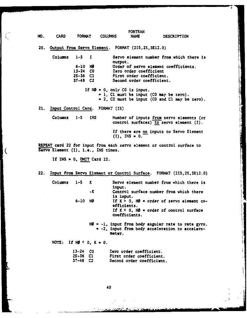
20. Output from Servo Element. FORMAT (215,2X,3E12.O)
Columns 1-S I Servo element number from which there isoutput.
6-10 NO Order of servo element coefficients.13-24 CO Zero order coefficient25-36 Cl First order coefficient.37-48 C2 Second order coefficient.
If NO - 0, only CO is input.- 1, Cl must be input (CO may be zero).- 2, C2 must be input (CO and Cl may be zero).
21. Input Control Card. FORMAT (IS)
Columns 1-S INS Number of inputs from servo elements (orcontrol surfaces) to servo element (I).
If there are no inputs to Servo Element(I), INS- 0.-
REPEAT card 22 for input from each servo element or control surface toServ rvo Element I), i.e., INS times.
If INS - 0, OMIT Card 22.
22. Input from Servo Element or Control Surface. FORMAT (21S,2X,3E12.0)
Columns 1-S K Servo element number from which there isinput.
-K Control surface number from which thereis input.
6-10 NO If K > 0, NO = order of servo element co-efficients.If K < 0, NO a order of control surfacecoefficients.
NO - -1, input from body angular rate to rate gyro.- -2, input from body acceleration to accelero-
meter.
NOTE: If N < 0, K O.
13-24 CO Zero order coefficient.25-36 Cl First order coefficient.37-48 C2 Second order coefficient.
40m
FORTRANNO. CARD FORMAT COLUMNS NAME DESCRIPTION
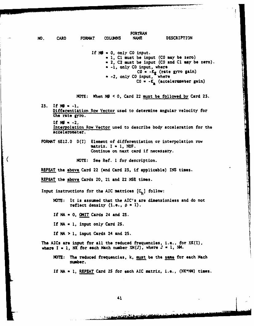
If NO n 0, only CO input.a 1, Cl must be input (CO may be zero)a 2, C2 must be input (CO and Cl may be zero).- -1, only CO input, where
CO a -K& (rate gyro gain)a -2, only CO input, where
CO a -Ka (acceleremeter gain)
NOTE: When NO < 0, Card 22 must be followed by Card 23.
23. If NO -1,Differentiation Row Vector used to determine angular velocity forthe rate gyro.
if NO a -2,Interpolation Row Vector used to describe body acceleration for theaccelerometer.
FORMAT 6E12.0 D(I) Element of differentiation or interpolation rowmatrix. I a 1, NDF.Continue on next card if necessary.
NOTE: See Ref. 1 for description.
REPEAT the above Card 22 (and Card 23, if applicable) INS times.
REPEAT the above Cards 20, 21 and 22 HSE times.
Input instructions for the AIC matrices [Ch] follow:
NOTE: It is assumed that the AIC's are dimensionless and do notreflect density (i.e., p a 1).
If MA a 0, OMIT Cards 24 and 25.
If NA a 1, input only Card 25.
If NA > 1, input Cards 24 and 25.
The AICs are input for all the reduced frequencies, i.e., for XK(I),where I a 1, NK for each Mach number .W(J), where J a 1, INN.
NOTE: The reduced frequencies, k, must be the same for each Machnumber.
If NA - 1, REPEAT Card 25 for each AIC matrix, i.e., CNK*NM4) times.
41

FORTRANNO. CARD FORMAT COLUMNS NAME DESCRIPTION
If NA > 1, REPEAT Cards 24 and 25 NA times for each AIC matrix.See Card 3. NA a Number of partitions (NPART) in the AIC matrix.All the input AIC's must have the same number of partitions.
REPEAT until all AIC's are input, i.e., (NK*NM) times.
24. Partition Control Card. FORMAT (215)
Columns 1-S MS Size of partition.
NOTE: The sum of the sizes (MS) of all thepartitions in each AIC matrix must equal NDF.
6-10 NZERO = 1, all elements of partitions are equalto zero. Do not input. OMIT Card25.
- 0, non-zero partition. Input Card 25.
2S. AIC Partition or Matrix. FORMAT (6E12.0)
CH(I,J) If NA = 1, complete AIC matrix (complex).I - 1, NDF, J a 1, NDF.
If NA > 1, AIC partition (complex).
I * 1, MS, J - I, MS.
Input by rows. Each row starts on a new card. Continueon successive cards to complete each row.The imaginary part of each element follows the real part,e.g.:
Columns 1-12 CH(I,1) Real
13-24 CH(, l) Imaginary2S-36 CH(1,2) Real37-48 a ( , 2) Imaginary
OMIT the following Card 26, if NA a 0.
REPEAT Card 26 for each altitude, i.e., ND times.
42
. . . . . .
FORTRAN
NO. CARD FORMAT COLUMNS NAME DESCRIPTION
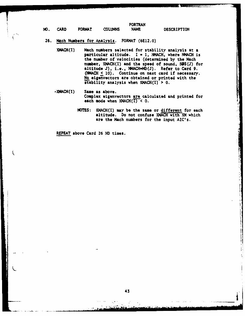
26. Mach Numbers for Analysis. FORMAT (6El2.O)
X14CH(I) Mach numbers selected for stability analysis at aparticular altitude. I - 1, 1#4ACH, where N?4ACH isthe number of velocities (determined by the Machnumber, XMKCH(I) and the speed of sound, SOS(J) foraltitude J). i.e.. !t4ACH4ID(J). Refer to Card 9.(NMA&CH C 10). Continue on next card if necessary.No eigenvectors are obtained or printed with thestability analysis when XMACH(I) > 0.
-XM4ACH(I) Same as above.Complex eigenvectors are calculated and printed foreach mode when XMACHTFC 0.
NOTES: XMACH(I) may be the same or different for eachaltitude. Do not confuse X?4ACH with XM whichare the Mach numbers for the input AIC's.
REPEAT above Card 26 ND times.
4 3
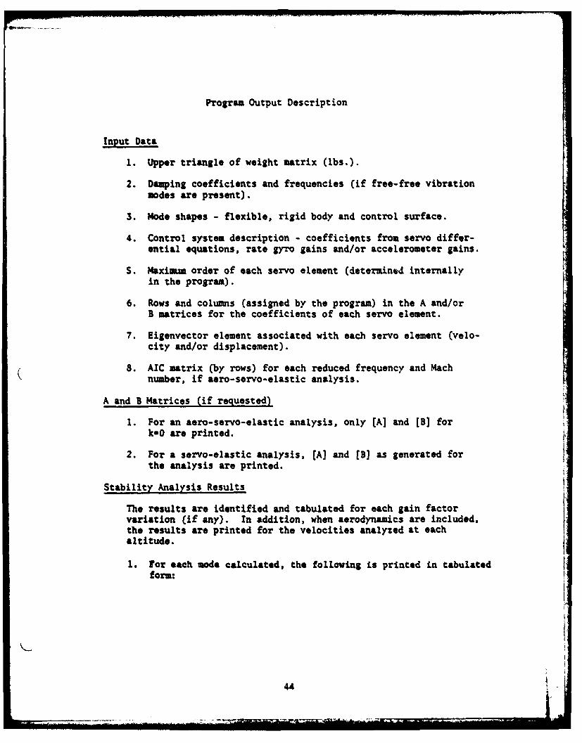
Program Output Description
Input Data
1. Upper triangle of weight matrix (lbs.).
2. Damping coefficients and frequencies (if free-free vibrationmodes are present).
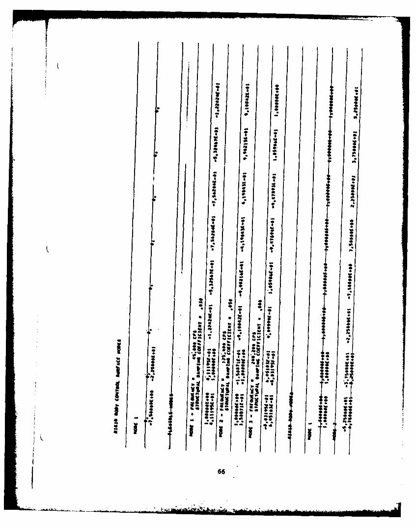
3. Mode shapes - flexible, rigid body and control surface.
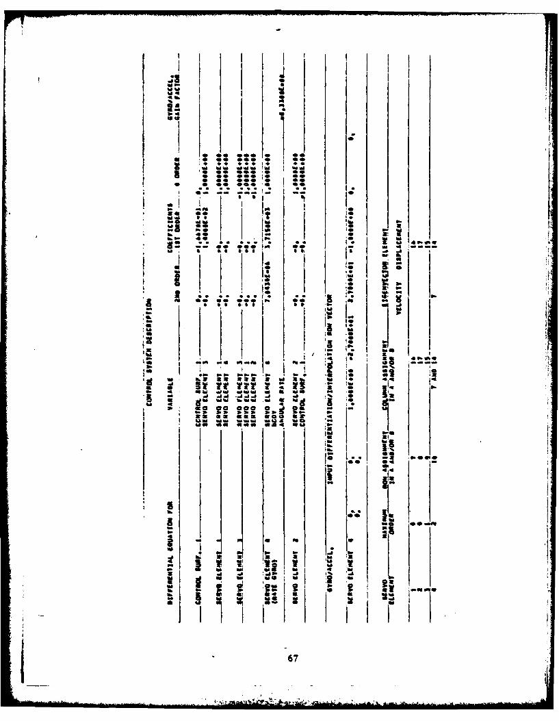
4. Control system description - coefficients from servo differ-ential equations, rate gyro gains and/or accelerometer gains.
S. Maximum order of each servo element (determined internallyin the program).
6. Rows and columns (assigned by the program) in the A and/orB matrices for the coefficients of each servo element.
7. Eigenvector element associated with each servo element (velo-city and/or displacement).
8. AIC matrix (by rows) for each reduced frequency and Machnumber, if aero-servo-elastic analysis.
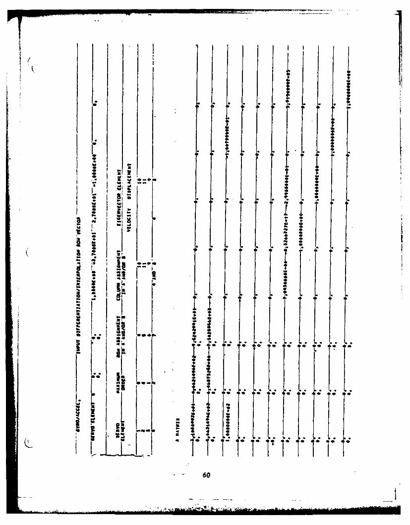
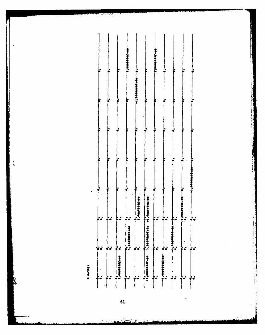
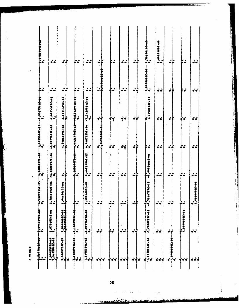
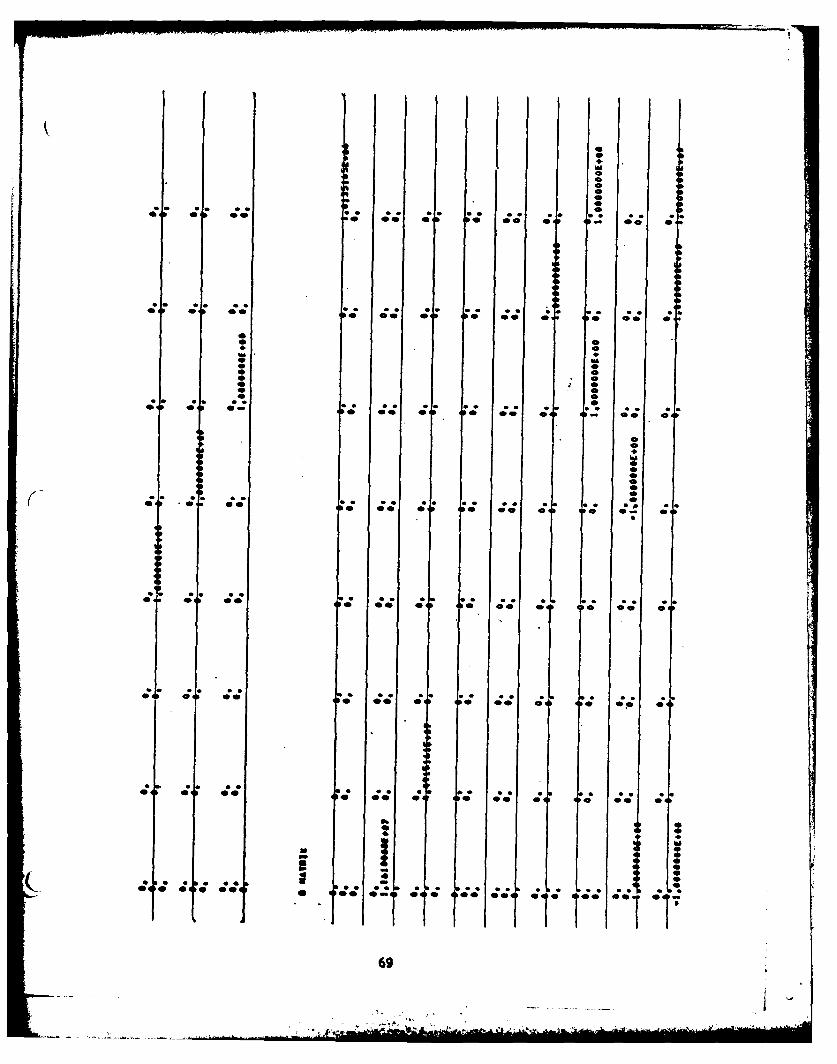
A and B Matrices (if requested)
1. For an aero-servo-elastic analysis, only [A] and [B] fork-O are printed.
2. For a servo-elastic analysis, [A] and [B] as generated forthe analysis are printed.
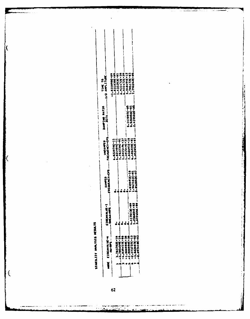
Stability Analysis Results
The results are identified and tabulated for each gain factorvariation (if any). In addition, when aerodynamics are included,the results are printed for the velocities analyzed at eachaltitude.
1. For each mode calculated, the following is printed in tabulatedform:
449
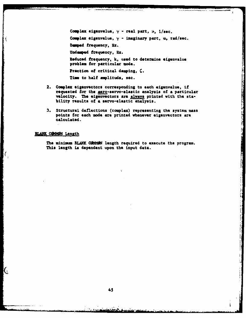
Complex eigenvalue, y - real part, I., I/sec.
Complex eigenvalue, y - imaginary part, w, rad/sec.
Duped frequency, H:.
Udeped frequency, Hz.
Reduced frequency, k, used to detemine elgenvalueproblem for particular mode.
Traction of critical damping, .
Tim to half amplitude, sec.
2. Complex eigenvectors corresponding to each eigenvalue, ifrequested for the saro-eervo-elastic analysis of a particularvelocity. The eiSenvectors are always printed with the sta-bility results of a servo-elastic analysis.
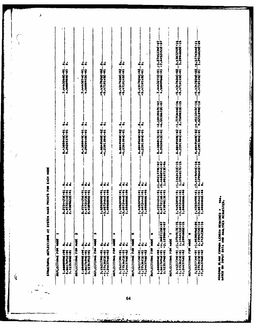
3. Structural deflections (complex) representing the system masspoints for each mode are printed whenever eigenvectors arecalculated.
BAKCftW0 Length
The minaimim BLANK C*M(N length required to execute the program.This length is dependent upon the input data.
(i
45
ISECTION IV
SAMPLE PROBLEMS
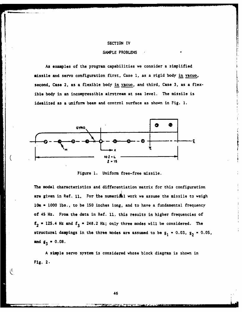
As examples of the program capabilities we consider a simplified
missile and servo configuration first, Case 1, as a rigid body in vacuo,
second, Case 2, as a flexible body in vacuo, and third, Case 3, as a flex-
ible body in an incompressible airstream at sea level. The missile is
idealized as a uniform beam and control surface as shown in Fig. 1.
GYRO0 0
Figure 1. Uniform free-free Missile.
The modal characteristics and differentiation matrix for this configuration
are given in Ref. 11. For the numeri~l work we assume the missile to weigh
10m - 1000 lbs., to be 1S0 inches long, and to have a fundamental frequency
of 45 Hz. From the data in Ref. 11. this results in higher frequencies of
f2 a 125.4 Hz and f3 = 248.2 Hz; only three modes will be considered. The
structural dampings in the three modes are assumed to be g, 0.03, g2 -0.0S,
and g3 a 0.08.
A simple servo system is considered whose block diagram is shown in
Fig. 2.
46
ZL - .
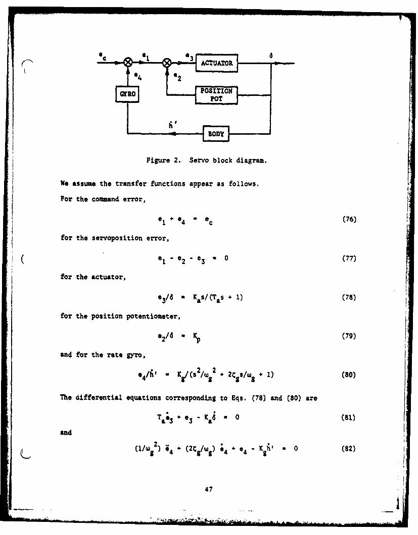
Figure 2. Servo block diagram.
NO assUMe the transfer functions appear as follows.
If For the command error,
01+ *0 a (76)1 4. C
for the servoposition error,
a 01- 2 ~03 *0 (77)
for the actuator,
for the position potentiometer, KS(~ )(8
0 * (79)
and for the rate gyro,
s4/hi Y c(s 2 2 +2 /.+1) (80)
The differential equations corresponding to Eqs. (78) and (80) are
(11w82 * (2C 2/w8 ).9 e4 Kh 0 (82)
47
r
The actuator is seen to be a first order servo element and the rate gyro is
a second order element. Therefore the second order variables are
(Z) a- (83)
the first order variable is
(Y) e 3) (84)
and the zero order variables are
- e(8S)(Z) 2
For the numerical work we assume Ka 1 /6 deg. per deg./sec., T a 0.01 sec.,
a 1 deg./deg., wg a 376.991 rad/sec. (60 Hz), C. a 0.70, and K. N 0.3 deg.
per deg./sec. The differentiation matrix for the rate gyro from Ref. 11 is
(0] - (1/241 ]O 0 +1 -27 +27 -1 0 0 0 0] (86)
where Z- 1S inches.
The case descriptions below present the variables in the eigenvectors
and discuss the solutions. The data input code sheets and the program
printed output for the three sample problems appear following the case de-
scriptions.
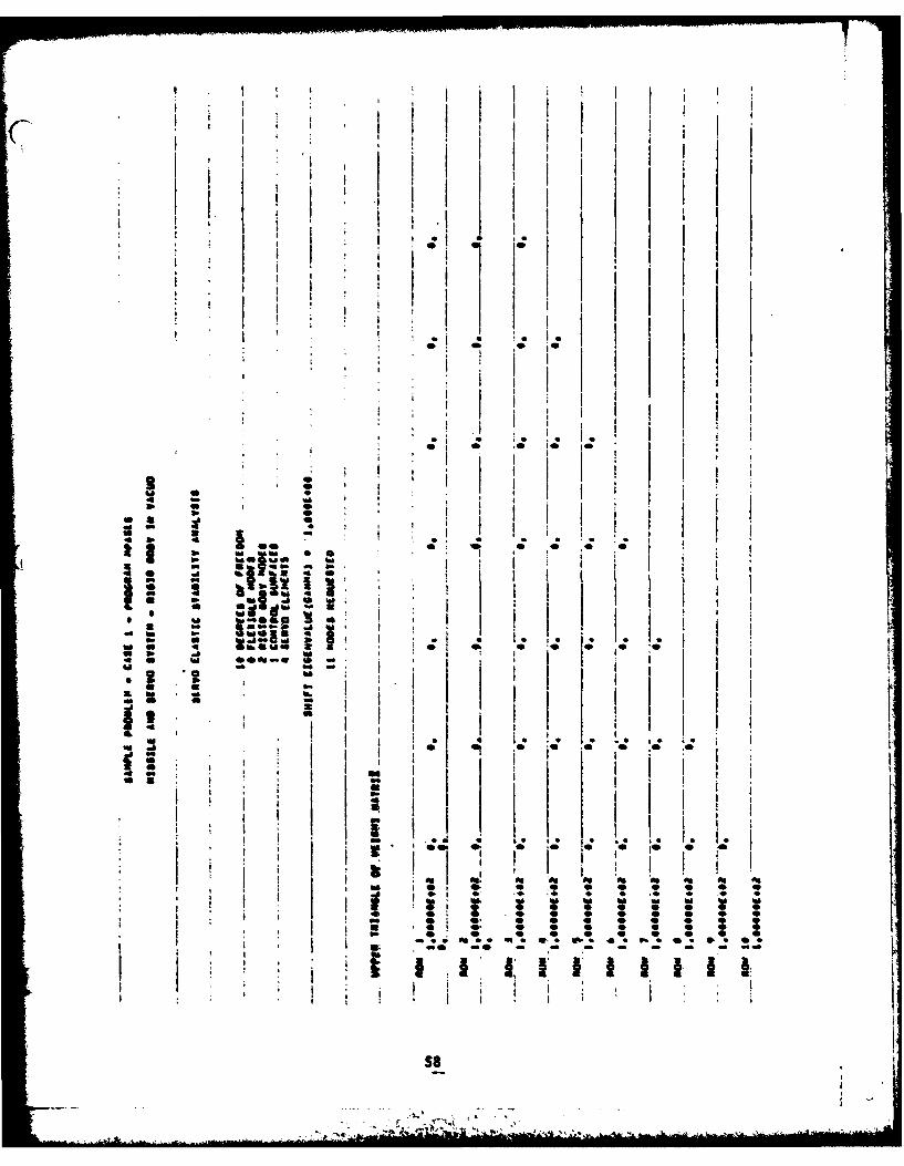
Case 1 Description
The first case is the rigid body in vacuo. There are two rigid body
(modes of plunging and pitching. The eigenvalue calculation is made choosing
48
r
tt
YO -1.0. The 11 h order eigenvector that appears is in the following
order:
{V) a LaRa A;4 aRla'R2 4* 3* 2
There are four zero eigenvalues from the two rigid body modes and four
infinite eigenvalues from the command error, the servoposition error, the
position potentiometer, and the actuator. The three non-trivial eigen-
values consist of the real actuator damping and the complex conjugate rate
gyro frequency and damping. However, since only the eigenvalues with
positive frequencies in the conjugate pairs are printed in the stability
results, only nine solutions are presented in the printed output. The
structural deflections at the ten system mass points for each mode are also
printed.
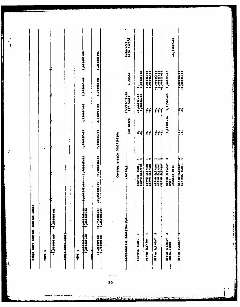
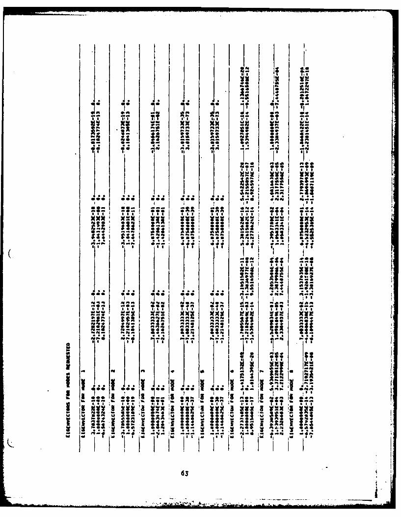
Case 2 Description
The second case is the flexible body in vacuo. The addition of three
flexible modes to Case 1 results in a 17th order eigenvector which has the
variables printed out in the following order:
~~ Lala 2 aFS ;R1 ;R2 1 *4 a. 1 a. 2 aF3 aft 1 aft2 d 4 3 e1 e21 (88)
The eigenvalues are obtained by again choosing yo a -1.0. Nine non-trivial
eigenvalues are obtained in this case. Three are those obtained in Case 1
and the additional three complex conjugate pairs correspond to the three
flexible modes. The stability results present the modes with the frequencies
in ascending order, the negative values being omitted. Therefore, only
thirteen solutions are printed; the structural deflections for the thirteen
modes are also printed.
49
An unsatisfactory design is seen to exist from the negative damping
in the 133.0 Hz mode; the missile, will "buzz" in this mode.
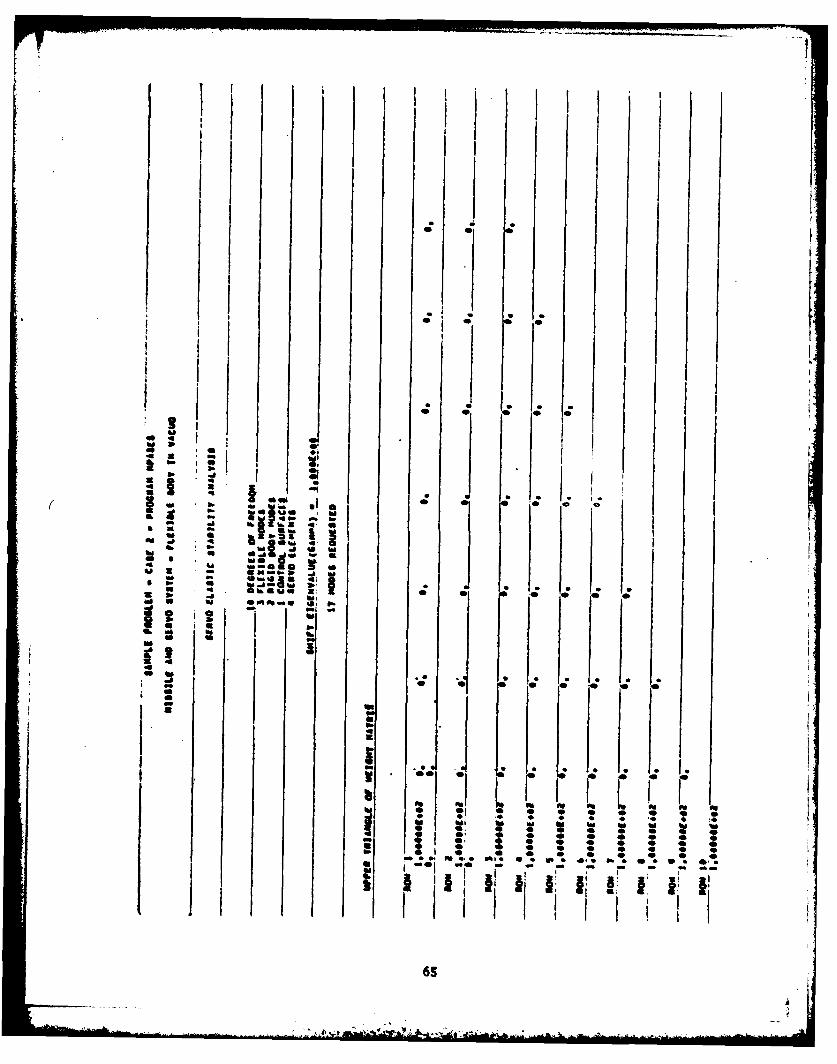
Case 3 Description
The third case is the flexible body in an incompressible flow at sea
level with a density p a 0.00237692 slugs/cu. ft. and velocity V a 500 fps.
It is the same as Case 2 with the addition of aerodynamic loads. The
aerodynamic loads are assumed to act only on the control surface and are
derived from the incompressible strip theory presented in Ref. 15. The
control surface has an exposed span of 20 inches and a semichord of 15 inches.
Five reduced frequencies are chosen for the aerodynamic interpolation,
k - O.0S, 0.10, 0.20, 0.50, and 1.00; the minim value of k a 0.0S is
chosen because of the singularity in the aerodynamic damping at zero fre-
quency when it is computed from Theodorsen's function.
Although there are 17 degrees of freedom in the eigenvalue problems
solved, only nine modes can be obtained. This results from the frequency
"lining-up" process. The reduced frequencies determined by the estimated
frequency in each eigenvalue solution are shown along with the stability
results for each mode. In addition, the time to half the amplitude as well
as the damping ratio is indicated to facilitate stability evaluation.
The solutions for Case 3 are seen not to be significantly different
from those of Case 2. However, we note that the short period mode shows
up in place of the rigid body pitching mode. The reduced frequency of
the short period mode is k a 0.03346 and its damping ratio is C - 0.1401. hThe aerodynamic loads do not cause a large disturbance for the (impractical)
so
r *
configuration chosen as the example. The servoelastic "buzz" observed
in Case 2 is still unstable here. More practical configurations should
be studied that have more critical hinge line locations and mass balancing
on the control surface.
5..
-it
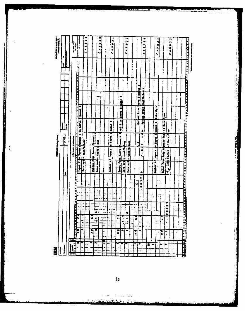
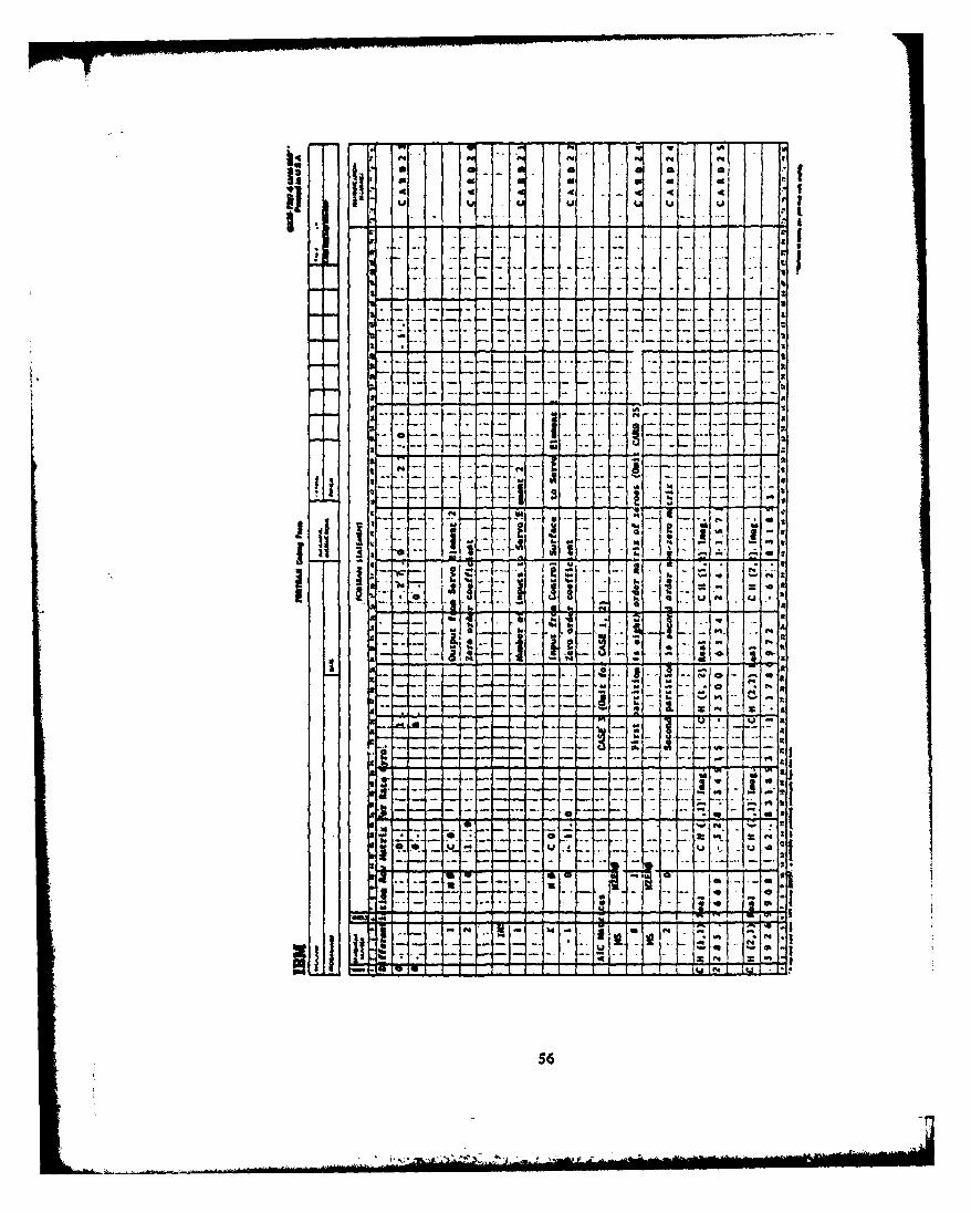
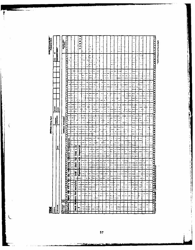
ir
4 ... 4 -
I
I
_I
.T..T
Vol v
----
- "
,
L
S2S
--
""-
-" S
d[- "-
.l. - 4" '
1%
$2a
- -i i l
f -t -111
11 A; I, It 1
A 3
r-2
.x
ILI
S3S
(4 - -54 - .- --.
-
_ - E ..E~:iYi :iJ .~ .4 .:..i:- 4 *Sd . U. U U U ~ I
- -
3
23I
2--- - -. ~- - . _ _ _ I
- -. --- .- I.-...-.. *
I. - 3J... - ... - ...- - - *
Ia2
- - - - - -I--... - .- -~ .. --- I
t ... .. ~.
-- A-- isa
I.aSA. - -~. @ 5. 0 -
I -. ~..
----- v- 14.1~~~-- -- - - - - - -. - .---a *1 3
9-..--. -.
* * 6 ~ -a~~-~* ~ ---. 9 -
- - - - -*
U U * a
* ..- 9- - .4 - - --
U -*I- - - - ---- -- *1I Aa -.- - 4.
U..
-.-- p9.
A. - 5. 3
- -a
54
iI I rIi I
~~_. a l .
9..
F I - . -F- -f 1
I |
1- 4- -
. .
4 . - -
S6S
Vdue
V
4
* - . .1~-* -
U .. . V111.~-~- P'I
3
I
- ~ -
- ---- - - . - - ... . .. - - - -. - . - ka
a aI a
I.a* _
a II I
aIt ---
- ---. - r- . aIII * 1 ... -.......- aa -.- t- -
a -'--4--.........-.--.. I-. -
--....... . aaa
Ii - -
- aaa
a I a
aj 111PK... -.ha aa
£- -. ~ - -- - -- a I
* S a
- - -- a.
I- u------~--r-.--. -
N.. -
- -- -- -~-
w
57
* a a I I I
I. *~iI II II I * !Ii4 i!~i-I
I I *' II 1 1 I* I I .1 ~* i:I~ I 2! '2~ I* 4 .lt Ii Ii
* II II II I I I.
I' I, ~ I* .!4: 4: I i Ia I I
a I Ia a
A I
.1 a* 4: ** * I* iQI a
3 * a I i a* hi
~ e a I I0 * IA I* I a Ia i - t * ,* * af U * I a II ~ - I I I
a * a a A A
~ I I I I* - - I* * a- 4 ~Imi 1 hi4~ * hi, ' I !
a hi I- I I 9
~ a 9~ * ua ~ I . * .
hi hi 4 0 1 0 0 0 0- hi ~t~hi ~ - * A* ~ hi *O~-.@U - hi-,
I * * hi IK 'K * II i i~~I~. I.
hi aS -.hi .*
I IU0~II~I I
I I I
A I I I
* I a a ~~ I ~.* .4 .. *0 L1a A
I 0I 0 0 0 0 0 0 0
* 0 0 0 0 0 0 0 0** ~** * .6 V~* * 606* 606
* C. -. no - - - - - a - - -
A I a g ~a 11:1,11
S8
-~ a~* * a.-, **~,'. * * '
0 wI
4 0
00
4 0 P
* Z @0 0o0b p, .
O00 0 0:-I a
100a
100
0z - Z-- - maM
S. I I . ..6 .0
USU
P.*A. I
ASp
mmwe
* a 9
I"I
*w
1* 6 . . a a
* 41L L
10. 10 17 0 *0 1
06
* S S * * S * S S S S
* S S S S S S S S S S
* S S S S S S S S S S
* S S S S S S S S 55(
* S S S S S S S S S
* 0* 0* SW hA* 0* 0* 0* 0a a
SS 55 55 55 55 55 55 5 5. *5 55
* 0 0 0 - - 0 0 0 0 0
* 0* 0*
* 0** 0* 0* 0* 0
.55 55 55 55 55 55 S** 0 0 - 0 0
0
0
N ~
- S I*~* SI
S S S S 5 5
-1I.4
t.Evlt.1*4
10 1
1. 0
61
*,Be
A 0 0, II
'ip- PSI
K q- l ef1'
6 2I
T~j T CI IOxI x J w -al.; A IIt
S, P.c p-
.0m ft em 1a
*~~ 0m Pe. v~p @9
1W f 1 vvf4 . . ft . a a .
Sol 93 *Ol 4,364
Asft P' -~M' ~ i ~Aft
0av*sop 10. * 44I 4
14 m 3 f"M%* MdaL * 6" 114. a.I 1:P0 P P 0 Ot
lb ft P. I F. IOf-0.OR I. O b 0 0..
0 00 PS I..Phajea 1 ? 1 1 g.. , w1! a1e we 11ie1?
63
' i.i f.f
11o 1.o SITs 0
I. I I
00 ft It s-ism A ; V III:.,
0? we 0. P
, , I I,
.0I WMA
vi e .g x 1.9:
I ft Inais, _ _
' I I II'II I
0OBI m 50 0,,0,* ,' I= O
we.000 0
' " w" t.* O's 666 see,,,"00 000 - - "" F
xIs 9 11 I
,N i o .,. ,- 0",, ,-=
It i A oo o o:oo090 ft P40 P.O N 0 P4P4
I I I * I *'
. " 0 I.-P. P
9-0 0Wm A00
4NO 00 -- W
1,o010 1 T~ 0 0 's 0 1 5
fil I 1' 1 to v64 -, M In
P-... . f. 1%_ - :A Q moo W .
I' Ii ~ I* I 1
* ** C
I * S S S
Ct.
I.
** C.
CCI *~ .~ K KCI @ a~ ~t
* ~ ~a- ~
C h~1S.UtItI~., ~..
CC U C 1.. * !*
M06@ I: I2~5&~ I . * .
~ C WI
C *U~~* *, ~. I1!] 1 - I I K
C U I
- I I! I I I"1 I* I.
1 C C C
CI
a
C
U .
** * LC C *
* 4 . * . s* C C C C C C C C
C 0 C C C C *C C C
m.~M .:~ :: ~ 3 : : 3* C C C CCI. * * U~ 0 4.. C S * ~ * *,*iia - - - - - - - -
*~ ~*.
0 -
oww0 40
* : VAg 0
* Ag 14
-0 a ;-
* 0* - a
Ag * VIIV
* VI VI
.. 4
110
- I
.i %A o
I I
4 "
%3 67
wee W 1 00
~* *0
I m e 0 -
fib; ;a ameV
3 1 0 3 *
* I67
000ft00000
* 00 0 0 00 0 0 00 0 0 -0 0 0 00
* *. a. a *9 a * *. a. a. *. .* a. a.* 00 0 0 00 0 0 00 0 0 00 0 0 00
- - ft ft
* 0 0I * *ft ft ft- 4 0Ag ft 0ft ft 9 0 0ft - ft 0 0- ft . ft Ii'* - m 6 -4 - 'A p.a. a* 0* * a a. *0 *0 ** * ** * **
* 40 0 0 60 00 0 ft 00 0 0 00I;.. I ' ,
* 6 6 ~* 0 0 0* . *mft ~ 4 ft
* - U.p. 0 9 T
* p. 0* ~* . ,. . . . . . . *0 .0 *
0
v 0.0 00 @0 0
0 o *I -~ S
96
~. 4 Ift L. . .. ** 0 0 4
.. a. . .. *0* ft0 0 0 00 0 0 00 0 ft 00 0 0 00
S
* - 0 p. 0* 0 * - 0 V* * S Sft ft ft ft ft
p. 9. p.- 6 ft 0* p. 0* 4 4 03
*a a a a. a.
0
ft* ftS-0 0 0 00 ~ .i* ~ ii
* 0 0a. a. a a *a a a *a a a. a. a .a* -0 ft 0 AgO 0 0 00 - 00S
9* 5 S
0U 96 ft ft
ft 60 1i~ 00 0~*aft* ft* 00 ftp. V.. a. a. a.. a.. a. a
68
-I~ ~I,
we000
*. *. .. .. .. .. .. ** *~ 0.. . .. 0 0 00 0 .. *. ..
S. ** ..* 0 00 S. *S C. CS CC C C *. CC
* 00 0 0 00 0 0 @0 0
0* 0* 0
** 0* 0* 0* * 0* 0* 0
.C CC *S CC CC SC CC CC C 0* 0 0- 0 00 0 0 @0 0 C. C. CC
- 00 0
00
( SC CC CC SC CS CC CC C* .. I* ** 00 0 @0 0 0 00 *@ * CD CC
*o 0 00 0 0 00 .~ 0 V
CC C CC CC CCC *C SC
N * @0 0
SC CC CC* 0 00 S CS S .5 5* C!C C CS C
* 00 0 0 @0 0 0 00 0
* C CS* 0 00 C 55 C SC CS C 5 55 C
* ** 0 0 00 0 0 @0 0
00 0
N *- 1 0 0£ 0 3 0
- 09 4 0 0
S S C C CC - * 0* 0 0 000 5 CC C C C * 0
* @00w * 1 j 1 *~~j*~ .~nP69
-'A>* * * *
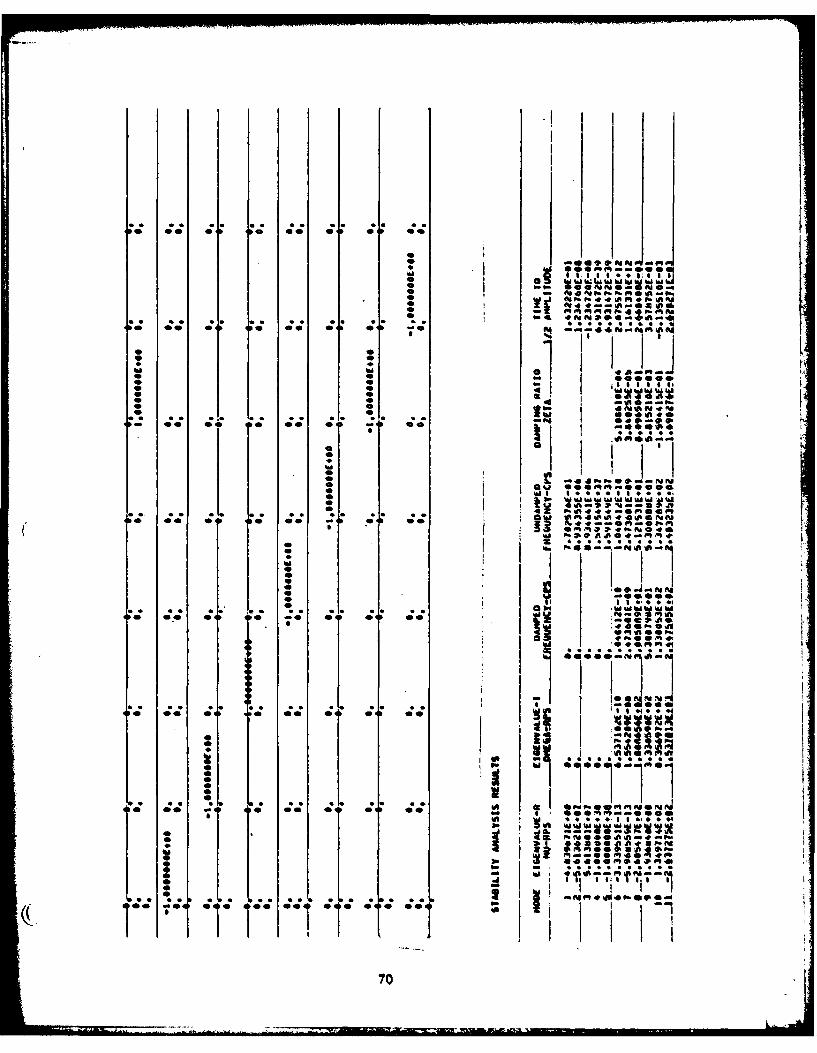
OR *
it I I i* ~ ~ ~ O W00 vd -. T9..
QS -- P.
* 0 0 *
* 0 I
"I 0 Ip *
0 0 4 0 ft
- 0 0 0 0 0 -0 0 0 .S* I0
0 a me
ml It
0i *4 11.- 0 1%~~ . .
*' 00 0 0 *0 If 0 U
L L
07
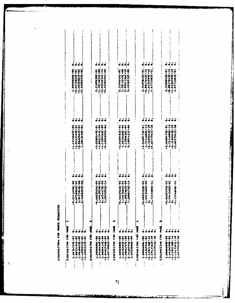
oI ^Iv
,nrorA '010~";peJ I I
0 .4 N0ot010 00..
0I1944 I WWW
0000 See.ge 000 o
1019. 00,0e0-440 00~i 044 0 A
iiit
0000, *,000.01
so0 009 000
0.4- # .01
55. 04 S P. ft I2 2,
ofeMf . %-0NI I
1 21 *1I
m w- ,P J I - 0
000 40 *000 0c o00wV" :41 I:I
140 00 ,OO 000 ti V:i 'I6~~ lisl -1l -0 .!C*5
71V
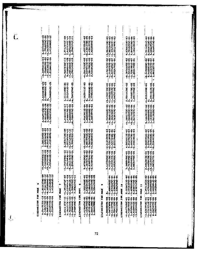
Oi fl g I
.*ttx N0i4. al8~ f1.*00 000091 *.o 0 00Ill lill I oll loll lli egg 1
~~Wla ;aW W U.II
-p,. go , I .Aa 14ft .... . .40 d) "" m0" .
-a P.0 0
, I I .! e I % 1 , *
:l- 0000 000 p00001141- a 1s. 44,, o.,v,4O
O041a Aa0.0 a00 Ca. 00
l0 0, t i l 1l l 1 l I l 1 1. 1 I
040 A P.0 ..4-..ft af
04441
* * * * I .
oo01 1oo cooI * I e oi Ig '
II I I
Age 0g 000o 0 0 O O0 0O000SIi l l e. I l i l l e* l ia sgi l al s
W W ' vowW ~WI4in1 0 ol 4I1 to a do 40 0 F. -
'a 0ft 149,Ci-pAg .. P1 0
10 * 4OO 0 I 0 0
W W W W I~ I W II W W.a IA IedW,. , ,
e10P1 Av e Ae 00 v@ I I. .;AN 04C,0 400 Clcoo Cbcooa I
us w114 a.o4 1l A: e4 tI AD 11, A
00 0 i "WI M;d1111 lil.. . II II... I I I 1
N 0.0 go00N-0O P. 1 i PPN f Q; -. 0,0 10
I. no P1--9 ft0PM A4 0 -0
Oai -N J% 4p N .4. -
*004a C P1PP4
WIMI- 'r* a . .4, . sa-v
*a .0. .0 P.2 Al- %'04m-I a4
0. 0N- -11 In100 , 0 ~..f a W**ie 0*'11
1 0lS *, ,, '01 1 1 1 1o
t..*44 -Y4iA N .%.~r A FE=t- **;CP. 0S 4 m -4
-0 Ad418 *1N1PP
tails .. .~, .l,, * .0 5 .5 1
NE210 ~ S .0' 0 4 - mi 41 11177 As.5 *0 -% o is I01 T OfSS 00 7777Ed0
3 *01f d O r~-4 1 *~44 2 N-NS 1
epo OP1C *a - ft as W1 - Mmomo14 * A A Iw " a 41I**.* a M4 . N M
72

!T V( I fob
I - ?
I -.
$is
I *4oo~9 9 *. 99
00 00 lop 00 .A
-l . % a %
000 000 0
I III | .
" ; P. "-
ii I 'ai a ""
, - 4 ".
0
4 4 ,4 i Al 0 l 0 4 47
:1 i I •i t I i Ii
I I I a I I I
0- "' 0-- -
3 0 4 Gtl .G l i 0,.,*Al *90
04.1
I I
I -0
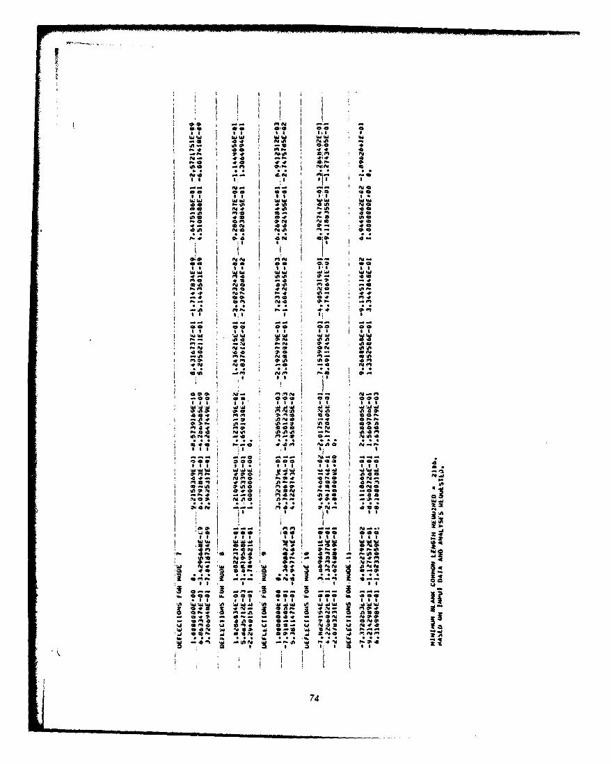
I
NO In00 0
00 I Iii I
• IM WW I !
P . 0 4 4
I . -= 4I
toO oo o aIf
a 0 cm .0
ill ~M Ilu wI IIIt
01. (p- -;4
P, . z S i ji
@0 00
I II
A 196 In A 0
* ON 4 0- ON
E.i 19
, S
m *b
.. , I I I I 'SS
Q: -, l it"
00 Co 00 0
"a 'JA I ll : I . w a
-. ~~~ 00 I 4 .1l .2. .Vv19
04 2. .II ~ ~ 4 AA . 8
* 00 00 0 00 @
In A24 14 0N 4 44m. a.I a,. * 4 a 40
40 f4 4 -4 ' ON 0a
MO f4 9 04 440 45
IT T
000 49594a No 49-* -0 IV, @ 00 ?.00
A. s *as e. m e'A Waa UA a 18.*o& 'A WV W4 W '
4a 491 094 w0 - 6
ft A4 09,4 a
*~a WNN N.4 9 0. N
* . .9 * SS S e* 74
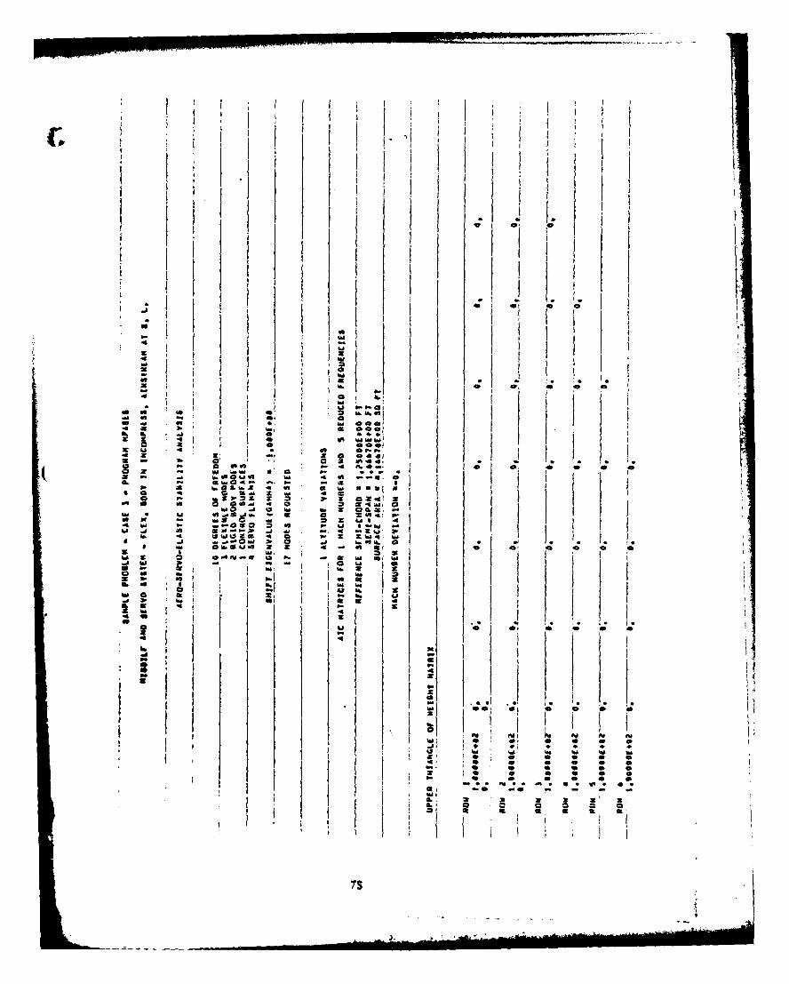
I I I4; .i
1 i I
I j I I :
1. J -a I.I v a
o I "o1 A.
O4,e; aw a x.
M ti ia
- I ,-W @001 IO
to w 5 -40: VA
01 a -
:e == :K A. . I I
4'rd . - i ow 4
(.- S . 4S . 1 * ." *
w . . .. .- s c 2. . . . .
.. O50~ U . iJ -~ ~oilU .1 S ~ ~ D .4 . -. 4 4
4 Wt*9.SZ 4 0 02q
7s0
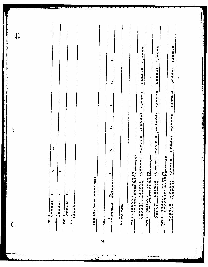
I- S* 0 0* A muif Al 0Al w* 0 0Al 0Al -
- p -
- - -
* 0 0
I S 0mu muAl WI 44 - 0* Al 9
*1 S aAl 09WI 9 -
* 0 0* a amu mu* -~* V 94 9 AlU' - U
* Al if* A
* 0 0* Imu muif .4 if* ifAl 0 a'a p.WI -
Al if 9* S S
0 .
* 10 0* Iimu mu
'aS9-' WI* U
* WI ~
WI0 - 0 -
*0
I Al * Al i pAl 9Al 4 Al p* * Al *0 ~ p* mu A. w - ~. 9- :~ . ~-
SU 9* ~ U- S U-S. I.
Sm. em.-. -. -
mu ~0U * * -. AmU ImAa. -. - 00h. WI 3 -. * WI~E~5 4 -** . * *EC ~
* ~Al Al Al d mu~ * -- -~
* . . . 3 4 *5 ~U 60 ~ *@mu~ mu mm. mu ~5 ** @~ ** o~ silea * * W 0 muO mu muS mumu ~a muw5-- * * S *Al SWI * * 3 WI.4* 0 0 Ib'* 59 .1.0 SAl *..4 99
'0 0 - *Al, a-I
C. ~ ~
76
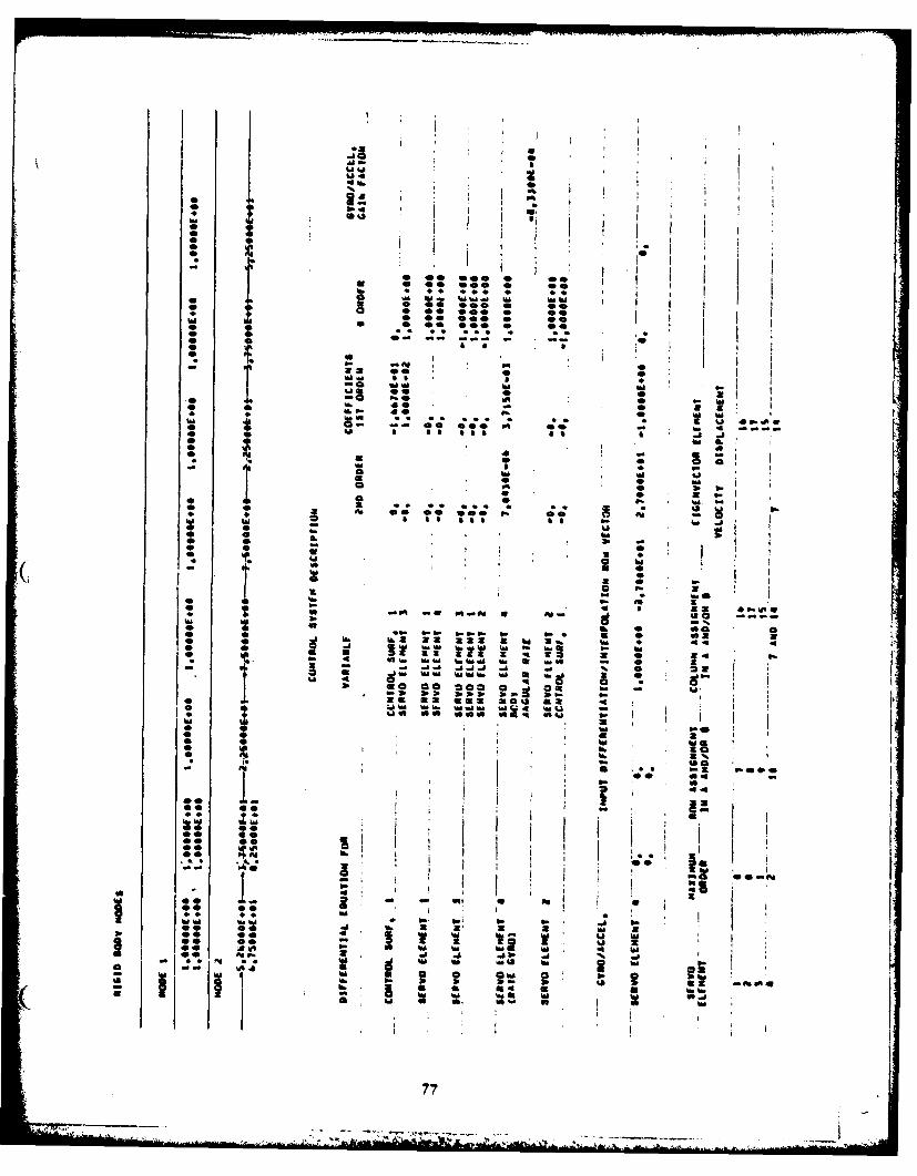
It
* I '
i
w ,
If.Q
° .1?: .'
M. A0 0 . 0 @
-b -.
WW % . u -
00
* ft -t
. @000000 *'*
* ID° p
* 0-|
77 p.
haMW - * U 4.D
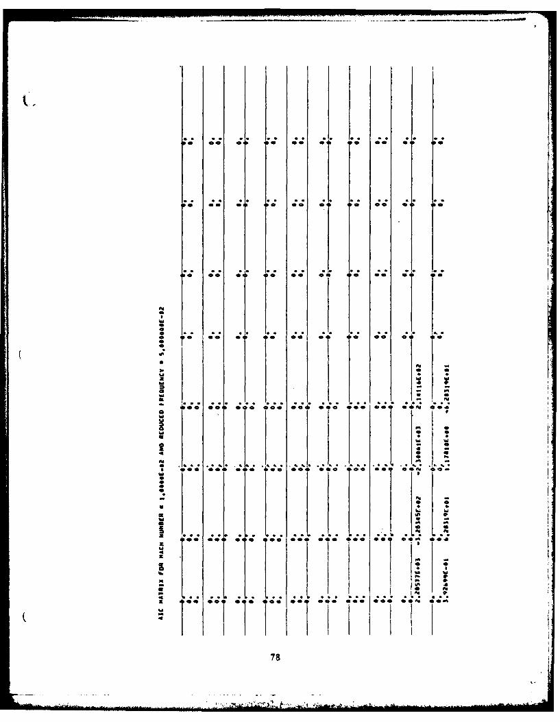
* *0 00 @0 00 0 0 0
to 0 0 0 00 00 0 0
tAl
.I . ... .5 . . 10-00 00 00 0 0 0 0
It 0 0010 0 0 00a f
ih
*0 f 0*0 .. lt
£hi Io 0
00 004 0 00
hi hi
00 001 Ole 001 0 O 0 %0
78".
hi
a hi. . ..U ,h i K Q *. p. *. . 0 ;
* a
U I O Q
78
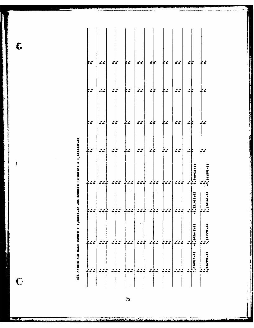
£' " '
.. a . * . . . a * a
II 0 @ 00 0 00 0
hi
I .'"-"
* U
* -
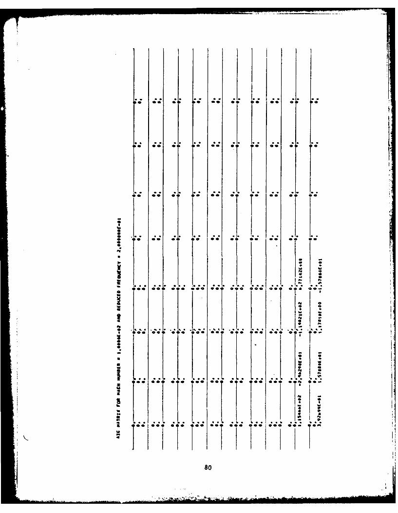
0.; 0 0 00 0? 0 o 00 0 0
*~4 0@ 0 0.* r~* 00
100 0*0 00 0 0 0 * 00
* 0 .. ol *0 so a 0 a 00 00 00 00%a
08
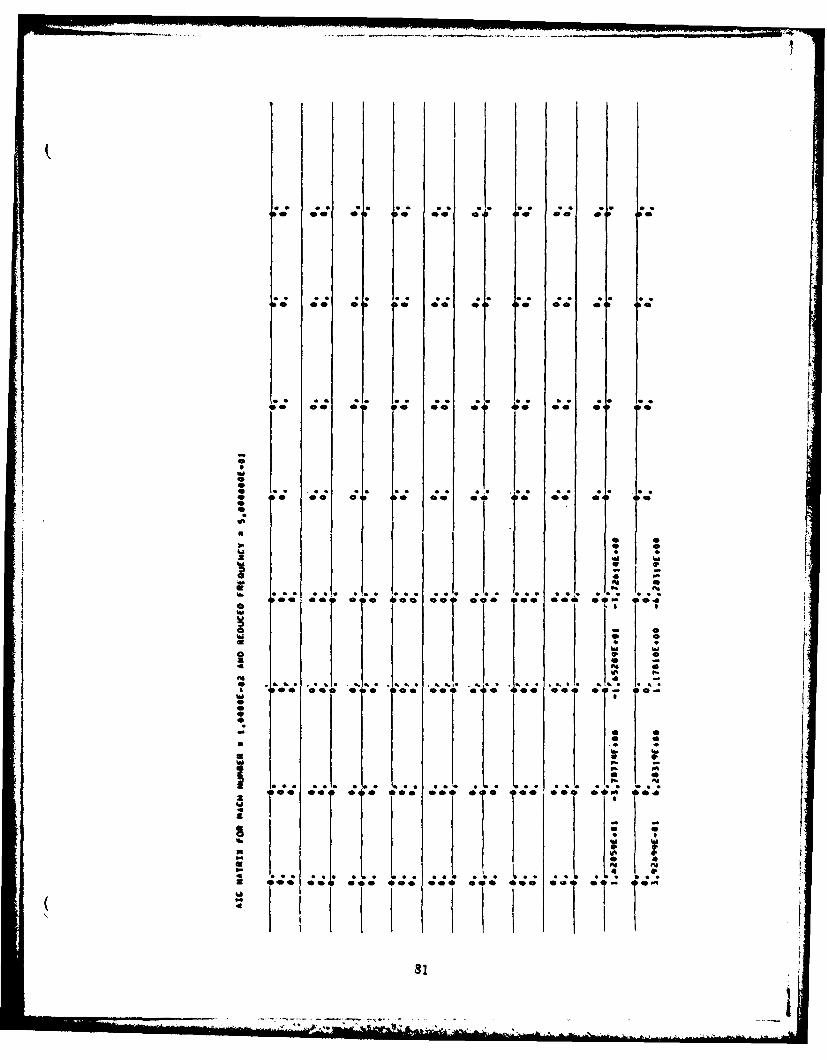
* 0 * 0 00 * *0 0
* C. . CC *R C1 ,
U o
C'A
- CC. 1
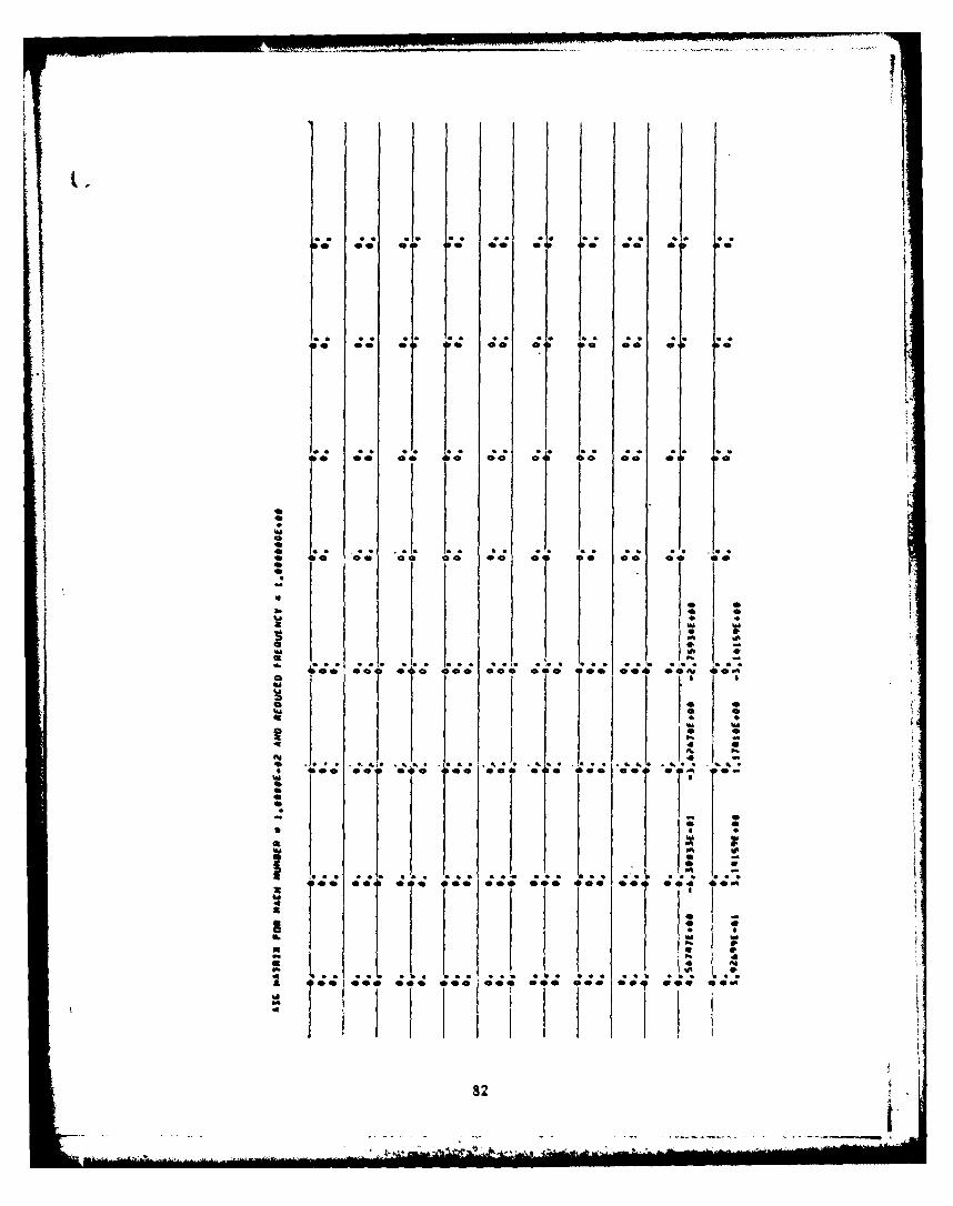
L.7
a., a .," *'. "a. *a a. a. S
* 0 00l 0 0
a. *a a . . a . . . a j
a. a . aa tSam
* 00 0 , @ 0 oa
0o
0 q10 .1.
? ?i
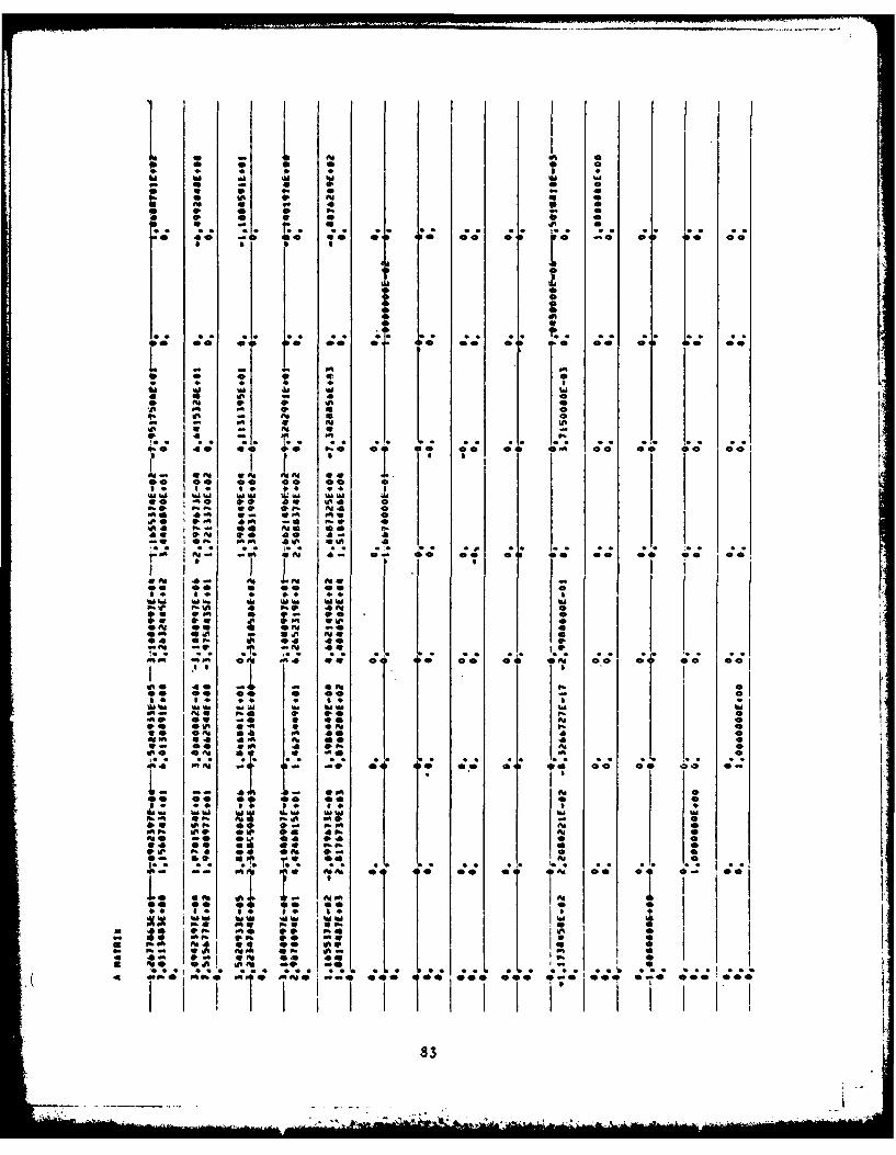
* 0 0
4; 0;D D 0 0
-0 Or09-- 0 0 00
*'4I I
4o 0
* 0 0 04
* -O 1* 0 .ao oo
41,
.. . . . . S S* S S. * ** * *00 -m0
Q4 0 .
I I
Al 00 I .9 40 a-A 0 I
V!. io. II
:9 IP Il to- -.0 .1.!.P I, ." t
mm 0 AI 0A w0 00 o 1 4
0. 0 Ad P90 40
-W OP. .0 4~ u 4
*us
PA 41l 4 *4" 00 0
00 0, 1 00P
I
I0 0
01
LDIO~4 4400 - AlP
0. P:.:. ; o P.e
0 .. . .
l e
0.
.. . "- '
00 0Al mb 0 4
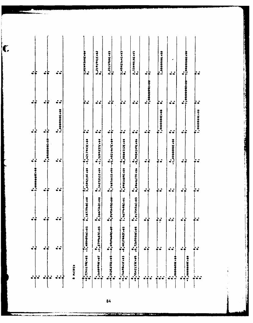
90 b- f: U0
b 9b 0 0 0 e - 0 0
M 9 9 , U 04
- .A * 9 0.
"t 0- O% 0 v 1o0.
I- P"* v 0o
0 ON ST
0 084
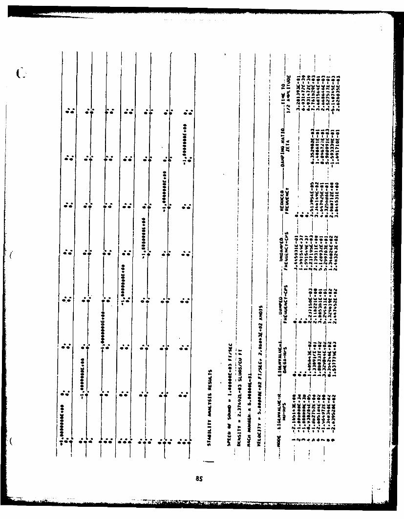
I IA
I k
O.*4
*I~~ Ol e 00 0 1 44 0 01 00
as ... a
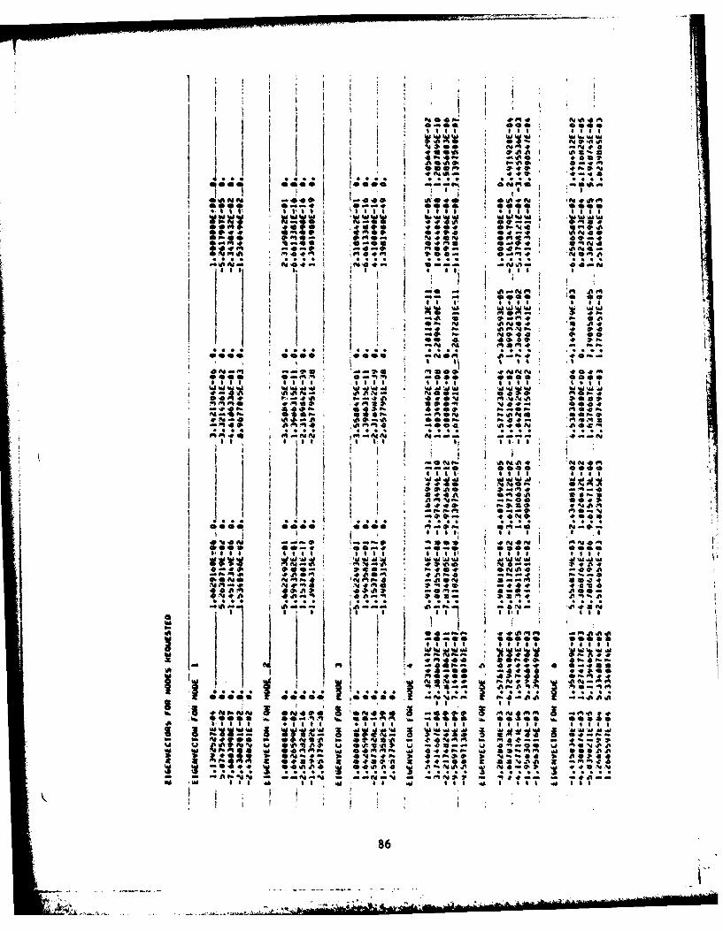
41 4 ft i -l . 00f 4vt41 -1 -1* o Iv41 111aII
opt: .000o 0-.
0 4 0 0 4 04-0
4 04;e ps a . , W - mo f
00 41 10- .0 40a
4~0 -e~- 4- vA4* 04, & Ii
ea. .00.49 4%
'Afta A .
0 0-t oci P.10 -a v
a* N4....S. . 0"~I. -. s e ez o o 11 - 0 '
A-ne 2! a-#
Ts IV
I A. I
~~M~I ~ N * imaa
1; ~ ~ ~ ~ *4 0 ; 1 Ph .P -a 45A A
*440 .
4% ftS I.C I OM-
cc.. cc- P.- aft0 a IPA 0
w01 $,I5 *A9.1 4O 1.
* ~..9 419 #03-869
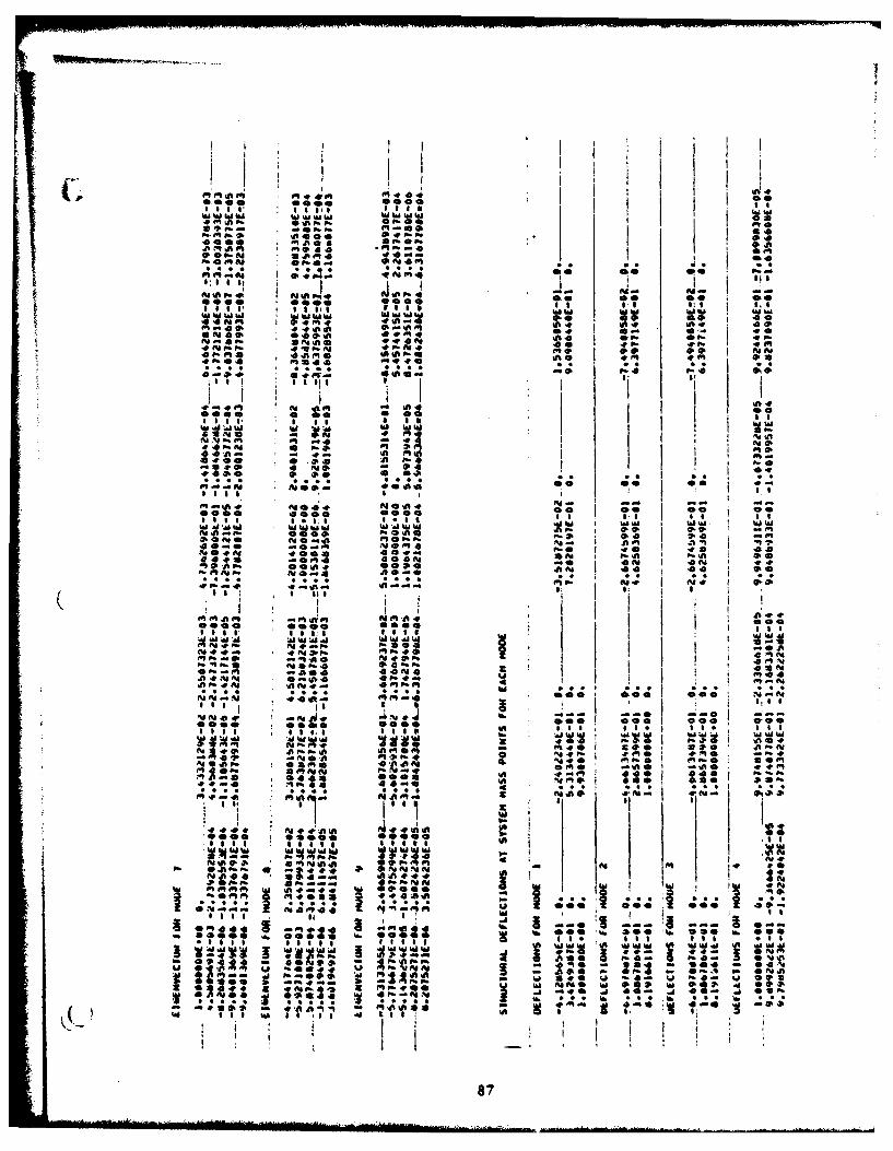
I I i
I °°*I I 1 11
ad 00
a q a q ' l l a q 4 ~ I I OlI e
0: S I St *..0 00 -
ip l l, Ai l.
Ow!
em. ec 0 OS
wwwa1 1. ofwWaIa~lAla
o . .. . . W1, 40 440 w 4e
ei46 . V#.P C V a4 c tf
*~ ~ I .n ON Q *.w m**- ~ ~
,S S III I i
a P. S a.P,
IIal
.4.JIII Ollllfl i i i l
ON go
i s e O O e o.00
"-'n I .10j 0
os.
• •o .P- e. *0 s Al I 45l s
5A~ F. 4- F.- M.4CIP. P4 V a& F% . .
a;! ' S0s 11 a t
S I As,* I a ft
I II ISIIIS III I ll I
p# ION" Op. 4;;6 IO4 m * P..P: .1 . I. 0 It -. 0 Ma 095
P4 A..* cr .. . * *5-ld05 104.0 %ll *0 40
is000 @0 0 0000 70 a w0 0N Al .4 in1 f"0*
onA Al 0, tv-0 ft5@ . fp..J 27M O *s o0 *1@
* * * ~~* la **, C* III, a*.
I I
tA qp
ljl4*1*4 It Ow P
OR00 see 06 0 '00
* 0
- ~ ~ ~ ~ ~ ~ .4 -S--**j~ -'iaa~-ArAI A 0
I a I it I
87
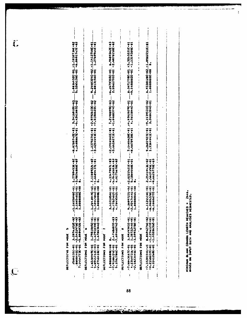
kiiP. P.
-; I@P. 00
e:0. i pp II , 0.'
•0 It
M 4
a II
. X A : M
P. 04 00
: . A . I II I.
P. flo. .4
,it I ,n
00m 00 00 0 040
hbmi
A10 I OiW OOW hE
I. MI 0 a 0- 111I
,I i IN I i ,
00 0 000
ole .04 : si7 im 0o a
I I IIEII III WI
N* -M-p
-. ~00 3 4I
ft '"A 0 an
.I I I I II I
ft 0 0. 00Z
as so mis
E~diIi
F-U NA 40
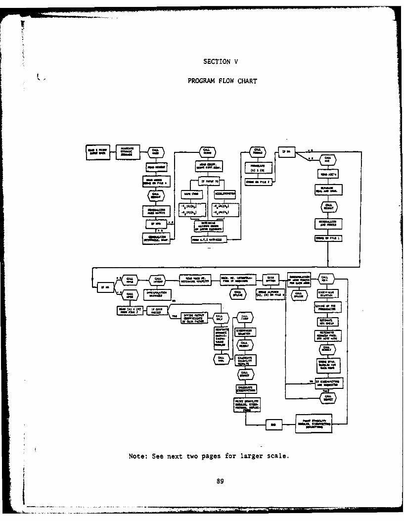
SECTION V
PROGRAM FLOW CHART
CALLC
A11011 ~ wws21.m.
11I-11Iust *1115anh1I.m I
aM Cl EM g . .. tJaA ANULl M
MUMIMqW~Z 11W ~tU 6mm U .a
Note:~ ~ ~~~1 Se netto aeForlrersae
01111 1011124189141
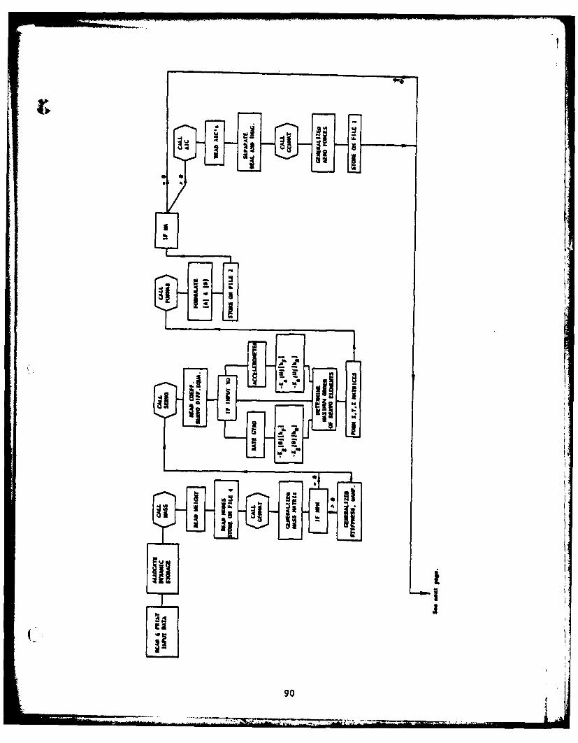
90
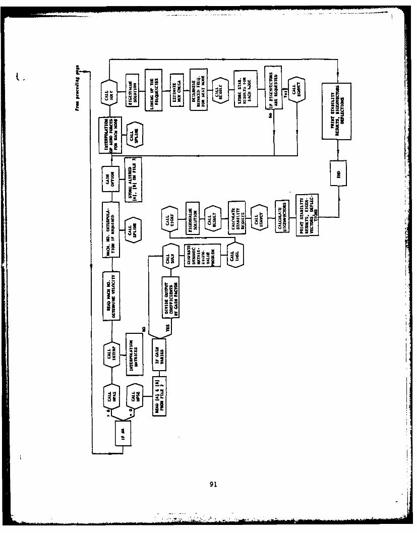
a'sI.o
til
CIII
I. us
i 91
SECTION VI
PROGRAM LISTING
IDU~A t4. iPNvu I ovuUI rIIApI ot Apt. eel&PC3. [At* I gApt,$=INPuf, MAIN4JOIO
.VjSb j~iI~jkU wjto AtmU-stmVUtLAAICS14016111AALYSIS "A INY63-J
.i(1. as I " It~(~ ALL___ _______1_We______ IAIft4hLI1012L tiftOQ14 iouAu.TrrLtL --U s4A P4406%
Fa I 30j i
C.J..TI NJI~"A tho I130LLdNU I _____ MLoIN
m:4c1,4pI A&J14% NA I 40160
14PAIJ~~i,~4P-6 11440~ VA'tjs
No-. UI* 1 4 ho I MA .4oz 1
am I nA.^I) I mI TL " A l.'ultu
00AIIVUL J I-ML II %~ 11u NI ____ ___ MAINUebil
pit 1 . NtoI A% IMA 41Ij j"t mAn iu Z.I 2# 1A I -jV 31u
10t AU4'3 s 20d I I "UFVI..INs,1CNa.0IMo.MtJu WA.44 313- N t_ LI*UI t I Iu I. -o. w- ___ "A hI o U#
140 1P u~i.a0 1 .u ". gA 1 NQ ).I
It Imit t 14*01 q. IU V AIA 1Sof
'a. IltftJ 1M " ______ AINIUSSO
du ossw0 %NaL i,%) "a-alNAtio
Uffilotul A L'eeJ6 oO% r$ l i j
N A L 1 o fqa~
40ONe MAZNU J4
92
I I dP nlfwft-l4 a
lilul*. ~ f ofo " .^ .. . . . .- _
I ratilomr*Ot"ft4oe£ilA '4h'it MAopl ,I .I - . -. & o-jQ
L I us t'.kejP *%'* pa I*4.V
it let 118-16.4up "a IN40n jU0i k a I I..*'eC4t MA NI fjr
I I a il*.v* *:I 1A etub0 No
k ejlint 14N.ol :*41..4__ __ __ _ 400u
1i -0 l Sa st l
1341i~ *gijj0.*JILL 2%wv. 4111LIoI*Ib4141JI1
I~ IvuII to..d ..t o I fio.afun I
for-b LaOWl CVT -ls teuUfILqfg IA %*PII Itm MA 1~ flu-44
fiP'al t.sI liiW i MAI.NLail I
- -- vel__ MAIsNs1O3U
ONW, Im.m. ON' m"UuORe.O-I- MAZI4ou
Al Iit. Iv4M oft I%;vC..-- w.ICwf 4AW&~ MII 110.P
I 1601 1 *rt4 1 .. -- _ 4 jfU q-I'
I ?ale I -I O4 ~MIU 1u
L&L eft06" 1 L% 91111 Alo)9(3 1- l" I 1* 111O l11 4I11
11Un1~.~4J I N 111ma1D41u3y"a 1.4 1 hrr
4 L u) MVUII~ 111~ w 9119 911)vN41O(S i 6 11)tl* JII0 0AIM290L
J~qjuA*Oj1 .d.Jj.j.)4AIN1320
ItO Tu 1 MI'LA
t ISOI I4'A. O^1 I144 ___________a IN I Vit14jaa&Au (two..4% 1 mahftlifu
IteI es I I I I lel~ft13soI1. I a I I m 3.11 1 AJ I I ________ ___________ _ajpI 140
llavulATL I N%.NAt*Pok-
£ k'aL n..*~ei~u~*4 IAI#11401
-- i F2UOOA N III__I_____..______hLf4AtSj'393 Frmo ..6JI.0 oqA INI&W,
601 FOWu 4 I Im 9L iA9 bkf~,?t ottI ANuu - 41. 1___________ MAt~i~O
66 wI LZU.I I " LI4 .SIAJI&LA1IO. S~IAILII A.fIIf, .L1Iae MAIN1630
J1UTUIAAWIJ %loolipJS.J..t~iuvselI MAI1440e
4JIje S.PO.Mftt*I,4.&djq Lp I1.II~a __________ PAI1N000
3e PJMTl.I4Anb mAAueetaI /leamAINselset ~ ~ ~ ~ ~ ~ ~ .!9I PIA~I~~ FPO .1kf"!Af to"dIC~~lLZ1AAf~j/ A'13
003 Pu4i. IIkO *A. '4"I"4MvPU 8k IL IAS A? V*JmI~I 8 IO&t41'IO1014093 POe*II ' 0594. 14 '1ff AC Ut t a IVP~tuUM0b" b!._o .I .* LOUL IN 6AI ifet
£e~bowe.g.IIN Milufu 6UI 4IL1teiOa.041Nk)1u1 UA&/~m *~I413.a~~~~~~~~~~~~~~~"~N %t.. A t-.bjg.~E~ Lt~L~IA1A ~l~ 65447
o" f *RvA.5~v~39M 94I .'uu4b t I,&I)kVM~lfSPM ANOlL.1fT 111&INI.Lba . . . *. ft- "M .-. ... 4.M aj . Fg_ m I.. # 4A - M._ _ _ 014141 ? 0
fI.a'#I)mu ub" w stv. 0.1.61 I toi
@4 U'A 1M;SAL4C~qWA' hCU A.&~jM~i ;UENU &uV~94I~ ~
141 mol. elet to# to 4.ghaOO.W0fctQ -1 0"1,SP6.1@tM6C *&$$code
F Fl*1 GIIFU&Lf111 "Mo NATION W&.--J
'ga 11M G0ioQiesmatrin poofter(oop one) a.10"(1011 (14.t cWoo(m4om.C 10 "433s304
B1~.(#s0.f 10)3C1 4901 c(F4 4G(MM3frco(MON),oaof(NoPft.0 It 043$4070
R*110040c 49&4 NutGM? PATIIN "A186:00
to %0 131143 *10110
@4'011S J1161*6___________________________ g.111,I*
It 0 otalko ".ssob'aSC 30 JngI*M09
34 .CJ~t~wtc.J) ________________________ "SIC *&
@40 Is ?e).emV 014110
11- imTCI )sT(f. J ) 11.j) 3.1 74 % ASS4411e
00 ho !at Nc sso.
60 *slU*obi: T.(cC10(J)J'i,mCF) £110tF9yP,%.Q.) GO o ?a *101
WR1?E(606b1) 1*50of) as lattilp" M&30
as o0 a f).'.g, afeo t 0604 1. I'lAssets*- u--is T c**4.:)goToi N1436
u~t?(,[email protected]:NR~) m330*54
a "loop) *4*110410w@TtP(e)((CMOOCZJ)u3I,1409).Ja.'.CI _________ P&14AS0
VeP001" St'.lSqAZZ1@ 31ZFF#4S3 £AM0 CARNG1404AZsI N&S31110
00 po01 m 1.310010 ____________________AU
__ ___ 1ME 43304
"IA30646
103 (ISMt(A~~,A)14&SO9%
* ~ ~ . .0~?~' .w3I~PV .S*S~ . P .hw .471 ./ A1e"a
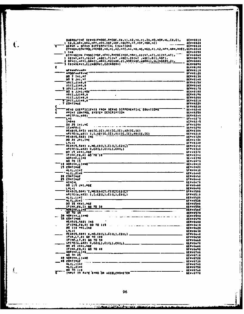
c 6 StVlvoo
00 1lN*?.GM *wEY(t N(tZ(6 hS)0C.M01 S(SqjOO?
C itj8. SlavoIO@
~00 6alosyO(J*JJallso
1291t.JJ)GO.0 EVOl7 C0M??t.ul orawelie
C..3E O COEFPtcFrmTU P3wo SERVO O1fitRINNIALGUATIOMS 6SII.20laIc Pat"u? Co mOOL aSSTE ctsc3Iy;o. avevoaso
-ey(660 SEu.VO210
Nu; Ps 31#4C S5RY02,14- CamP*.1 SERV024oPIA@(5,S03) NO(CIC ).xI(C.C NICCSIC) ItNvoloo
- mA110.10a) mNO.c4CLI.CICLl.Cl(C) &E*volih0watIC.6~23 VOCICL).CL)C@CL) SVaval',@
- fitcillfjo~) o0O-*6 ERva14
40,COW L)aWO Sk&OSIO9
Is CONTINUE SQ01
-- MLC~lI.MSERVG'4sGat COkt~it SEmvos'%0
mIkCQL -- SE avG 6700 Its J9O.SE Ar3fiall I
'.RInEt&.b@3). 1.Z.CRCL).CI(L)COCL) arFivosI@
00 3S Ka.11SI SEIW0Ie0IPCXM.Iol?) so O so 50 *imsso
StAft(sSeS) 143 SEIeiO04PrCifts3.II., GO to its S. - ERVO61*go Its 0410148 SINVO6241'.910 SCRVOS 50
- IA6S@SOa) Ksm0.CS(L3.CI(L3sCIC) fovoeftoMUO3LT.@) 6go TO Ito :~:SIF(0.L?.6 40 O SO 10 SEv bS
- hI!Itb6@?3 W*ClLJCCL@CLL............. - I.NVO67?@00 as 4Ma8e11U SENO46
SO 1110N goTO4 giEMV0600"60 ?O M234)af SRVOTGO
_4S comeI lot SEwwalso(ML CL~tB 1 3)637
so Ito SUOe47?*%Pi~ut TM NAa~ Gv*O ON £CCIEPOPCE -______ ENP;
96
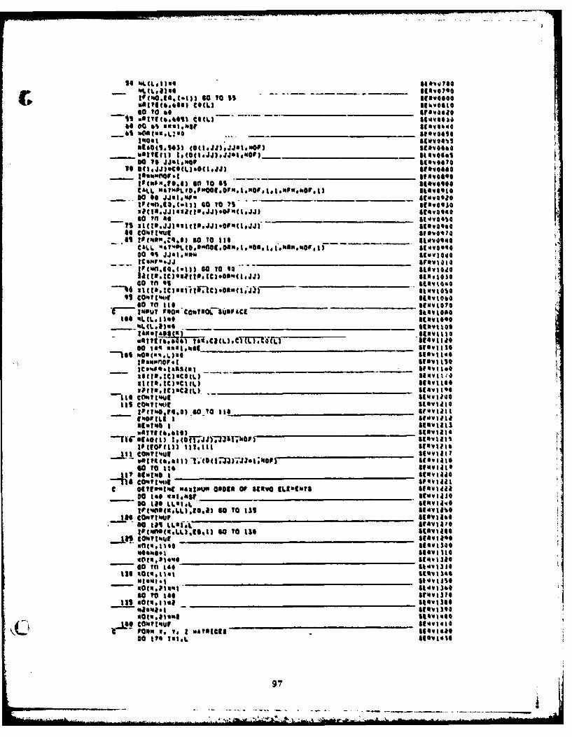
1 4 0S~.~ soCL I)* toIa
04111(e6*1 CIWL
00 6% uwsI.11mar gee.
CALL 1141110%. S 1 6 0 10 Apl Ii hr Iatlet r skv~olI
40 ColottUtwel--.A SIF mm4i.01 so To its Ui~~
00 $1 jJ61000%Iuwoo
- So To Itse __________________*scolvi@?INU 9400? DaCoistmacSUNPACI kl14
UQ046,6 *r fam)eTltb ILItIJ50 144 11,48101481 _________________________ V~util
Ile ______________________ Se I '
11tO I6 "I#?ut , Scovi~lle
-111 CON114Ut hwtI- [email protected],@) 610 II, df")e~mIaMt I
sla@OL I AS1MG
*IwI. 1 1 LL.' Iiirtr.1A([email protected] uomo'.1 1V 1
tF(CtOFWt)) 111.11 sToaescaw ut.
.- II 10 rtIC Scoville
'lo eo' *Is%$ a, t 4
SO061 IS SLtLaM.IOVIS
so4~uL.~)6 To 14$ 1uuwtaS
1401,48 1 4 Still o9mPotI18,1L11011 1110 S 1wII114
mFORN Nos SIOVISGI0014111L sov itol
MEM ._ _ _ _ _ _ _ _ _ _ _ _ _ __ _ _ _ _ _ _ _ _ _ _ _ _ _ .... ... .
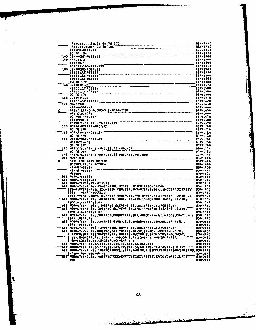
1I(.6.onC IO ItIt ow_____ Iv4 44
Goe 1 0(*~ lie~e
Its n (4L tI ) ____________________ ____ ICUW1SOC
111 1UUO(40(Uic) SIt melii
vTHICflsC1ct) nmoviise
* __________ ____IfVIS70
go TO 170 311(0a iQ145 JJanntor,?) Sl~vtlo
- 1!.JJ'Cot?) a.._____________ Ilavla070 CO# T 11Juf
C o Dgtt r Fvo ULE"E1116 0INFRATION 11FV10114S
00 Poo 1810439 Ia'gbs?0.
tr(NOtt.11.l3 I~s.16,;t6* t.r ~40 to 140 __________________________ IEVI
go To1 Itosftl
UOI~kCIII toS I Ilia
age cw4 pdjooiIM *rv.too
UIp f(N GS.1)0 RETURN____________________ 111"V1S3
143 DflS041(acta'61 - . - .. SE'.1AI
600 sUmpart(1'4 5Gi.?SNCO~rAOL *STS11 OISCoIPTjOM//jjx. ("11i.OP EQAL(UATION Paa:SwRa(*g.iCE7C1?5-Srm'.t'oo
11010 I1'0,oflaC4R.1 1A1J17bx.'q0*tO 040SdN99W13 01190107"0?w FSf9.ICI ACTOR I) si,.v:ito
--%41 FlIOM4T(IWG 11011WCOkYSOL SUN?, I3.i728130.C0N13UL SURV. 310, 1I3I t(b.4*tP49t1.a) 131
642 roI.'a?1t *5,,llwanvo ELEMENTstZ.G~91..'t3
1 94"AT.1011*,1036O IL"UVI'0@1SEVOILEO
*05 Plu,"At" u1WUt ~)3S4ui~~~*3&.~.RCt SE~viloG
-446 Foomay(Iws *9f130CONTOOL sur; tSIEtUVIS,.1Pt11,
66 )7wMACfl.411I50.t..1,011.ITSE(NMI.WL,( ar'.vaoloI 17.5.OIF*lw.3aIi & 'OOti7RFV1 NOQ 41 ViQ40a aNIOZI.1051CUh 4 IOO 8011 sEIvl~os
660 poe"AV(N..:ctaanz"a.I~oa 1me074-649 FOINartiW U1.5.11:h,5.Ia £OK.3.i1xI)1'ia
016 ?ON41(f1 u1N70A1t.114NWU *PIVa k:'TIOSNGO1AyTOw RON VICTOR 0#1 SINV41061
-- r omr UNt imso am a isE3Ir-tamm-7ma u;Rome ana I no I 1Pat I. , i r a 1 1a0(NO aieV4*,o
98
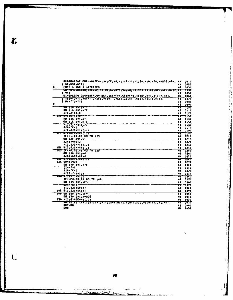
I MA*W3te.T7 As Gale
CAs 00000 119 1410pirT An 03100 tiJ~t0, so 0tt0
00 113 151.mV As @14004J 1t5 JuI.'1C As alsoXtIMT8 A EI&,.S aN 14JJaooTc.J as 0170AC?.JJ)*W1(?,j) As also
ITS .ai,.ijim.@TTjj 46 giva0Zf(mt,10,0) Go 70 12 Al 020000 1i0 J'l.'.1 As 0110
---- WI~qLu Ad i0f4(1JJ)VI(*J)Aa 0130
tat~~~~£ 0160~vQjj)a Gt11I~7~iii'.UIU J ~AD 043T
*a ti0 4ul."0 As oat*JJ~.'.C.'l.Jas 0270
Miot a. , - ('eat.Anrgear131 CON.v?'UE As 0as0
00 isif 18I647C k8 0300
Jjtbitc.1 Al 0310
(10"qE1,1 GO TO 146 As 035430 tas 181.'4p" AS 0360
47vqr.Ol i 037A(IJJJSCPctU AR 0380
145 U(1JJMSIM As 030Iwo 19Il IVIONPR as 0S0Z00) t50 JolompOol Al 0sl0
130 AtI iU1.uitJ 10)as 0610uu~~~~~~~ra~~~~~~gj~~A 943011IMT~JINIet(.J.U.t ,JI.4r nOal
Refulu. Ahe 60Cio. As 0650o
99
~uuIu~ IM.WCUF, AIC 00le
%A" SIC Ouse)
COpwLtA O.P. SIC 0080
I~~ CaCtv -SIC9vi1 PI r('4W$ *)4U .~I.Igi oS~ofo:o1j 4AN40-.6U ,1M ioslk IC vi1'0
U~2 IJ ~wit~aSIC Vito
Popa I aft SIC silo
W 201 l 1u IaI.. SIC 4iuU41 'du ,jok.:.,e SIC ,dIuo
__@c cijitoi.a.1 ____A I SC _0114-)M U al. e.'O" IC 42JU
ftweOpc -~SIC 01tJU-- UtI(.MitejI %,ikp, 1_______ AIC v0020
ALC u0
410 ow af"81 IC q29J
WM ru 4f44 ;IC gild31EdO L'4) 'et 141fil SIC OJI0
cia 641 d~s Iato--up SIC Q.)'0d"~ 0.09l46#0) 91614 1 ifl ..Jal #FurI SIC UJ*AD
C __ to~kv~mSIF tA 4p-6.j A S1. S1&EqjaI
~u lu .~l.4* IC 0410QC,.~I I..J)~%.~6~IL 1141 ,. I IC 04111
C FU-04 W.'4q"SLliku -bvitU P-19CLIS &CC -4 l jIJCALL AM ICU44IA. 001 SIdAC _ufS'j1
1;4#6. VtAI (ClftovoovI.IteI ol m; o fuutAQUt(.,%Alfi(t. 9~*OWftuP 9M or*l4 vt9IC W40UI *iME IC oft 11
momo'ut) AIC 06-u40S QW1I~40C AIC osou
_..j4_Cu94TIwvA____ _ __a-r lIq
,01 U0f.ob SIC Oslo
616 O"eS4I1i.i.nveI PUWIe~ 044ieCM KUPIG~i a 110tiI.6- SIC 0sso1 2%0 Aftu h?.1D1.LtIh 0"UL.4it'4cy 4 110tIS.6 4f) SIC W664
%17 'APU~e 06M.Iei~~D AIC "YO0~Nu SIC OUT0
100
*~ ~ ~~ I( ~Q' l4T..AtrJ j~f ?4t.N.TjiL$.A0A4..UUEq7) . OOF 00i T) * MI'$t Q'9_
c wlIN hfT I .- d.'I MT__Al__I__EIN ______IN __II _W _____7 1 1 _ FT_ __ 1'~ UAM _W00
CUIPLziWi. Vt .t.FL ANON"*V mostUUioI
c M60SF0 IOU
W(4 I NijI. 2 p1J/II4 I'lf)
A01dA II I 9N ) 1 j911 NTTI ms )I
4.10I 10 mpde 0 1 T
110 11 1) w ).U 10bMPIE g IJ?'
IIAiI.e..I 0u r-pSS T1
A II J I .as I I I ,j I /'A 1,41i I 2 3u0111 *t s(I I-1'AM 1p IS 04$$&u
11o AIzA(II-jj Mo?.,J30l_____ iuIl1.J) ______________________MOSE0252~
OiUm 4I LL.0) M00.ffM3.
AEIILLIS-1. -SCi~02SS
A I 19.J) MwI PRIS;ii01S4
IF *..VCNI )e. 0.1 (v o 13*WSP i 2 Y
6O TOt I d% Most 0 30113 Wla( j.,1i __ __ _ __ _ __ _ __ _ __ _ 0 30 1'
1)0II" LLWI. "SE30
AIII.II)ueII.1,Arl6 MPU1 0 1700
6 11190 009 111 J)J/44IN 1111 MOSP 0 33~060' to les MP 0 J4O39
AU 119 %.Lat-J2 Mt.'E034il awI d11111i t 1% 34
120 ntumf-.lvilkO. b "last03SO
__A(I £1.J.11 RAI Tp~ Ocj/GIMfas gQ
tfI I*JI ijI 141 AMINI UIM101a V
WI~os do, Ia.'Ia
c frht ALu 1IJ4 E~~.AgWle1 .1aI4f 0 s
ow IT&V Io10
opt Ia T& I uh.I 1441Ui
6, sl ft C~et?1 '*SI s tWO
...iao.. 40 4bg. d I. (a it. IJ U,4)-B.LaL I~k toI... P~ 9
G~?o. To I0.eN
£NftC*~I5)WL(1 3JVQ
17 w Tt i v Ito I ~. I vi I 1 jI tt 1 I IT N'.0 3
.Q_ VIaf tIMFq.O.U 64 U 118JU$.ms- - .~S~oa9@.
l~~~~~3T 177IaO ID 'Ae.t
moI %Lm..777e1 4~wA 1~ 1~A3 1"PCI'4 F(rf*ULAIGEGIJ~.
*a FmN L-..1g~~&,I.t VULI TU~l 1?) 1M#06, 0000S ~ I Fw A(,,fj.jA.&n t-t .9 Uars s3..Alu SV IP(t :as oo K
IT'SJ~ mptiMea7(6,s1 fnpj aIm aL'A,%1,9,uOfA )1 Mat419I918194F JNF41 -UI I $400E It
01 &6is. ImuGi ;0zt t66l~~ q*LfU4&4 rajjs41t3 4U 0Pl)rjo 141 ol-mol,1U1o~b
- -wK It *0h-0UU 1060,1 M51 0 V~etIP .J AI.IL0,.Iu&Iub Most( 0 7 7
...... Ab ~ ~ ~ ~ ~ ~ ~ ~ ~ ~ ~ ~ ~ ws- Too*IUt J G tW~JM~U.W~ I.....~U@3)I /ilAIl6,IU~~i~.))3MP11Oq4I
Ia.l )WNA ILIjA moi .CUUL.~.L.Lt4 SIL.~t&E ~t d Istll 00.&(aTOO.(0. "basio 101
Si? I4-2 V'atloJMiu uVLC-u P- 6.,IUl.IIhI.33 "1110ANUOMICAW(I)FOLill1 POEW430.
IFIS161.hoso U0 o n?0004044
Iq I L-v i 00' i4 ^--to1 A 4t C .L 10... Lsim01 .' 1IAlllo ilt sif 19 ALs I&P V1,01 Mf~.AiG 14
g I%..A 4q gQi.fAp~qftU It.g1, &PO~t"O #.t t g, if-% -01 A .O.ftI ot#v~h 'A4i P006ujUf
Cdolfl *.tJS yI).sg.AftI. mgo.~A#-1 04 0 qIs0t4ft 0 &1411 (1 .- I.s~~~u~ssq.I-A ts94 "It-10 06* i10
,..44p% '4, tol CI I $ wko~
C ~ ~ ~ ~ ~ ~ IA 160 ~M.I1NUD.QC*-'b~h tc-,0(~i, J IC1N.AU"VC.* 'CdL.-LdL IN'It-rIi,.u C
AA5O1 MA,% Q 31-- . w NSU P.A1)Q.g!Q .
UV J J.9Sj *J
4W"*Wt .0011.& UQ V gv3 _ pol t
U ov IV~ .N14111dogs R ~ lo j - -__ _ _ -r.£ ga
_V41 T 4V ,~sMv~gy
UO lott #t,&,Ua
IF toLs.' uL I) A ?Vi .
IV .&u..o polso&-s Mv ulboot
i%Q CALL 1,111* :11toll
no 0 1Nkb I mo %a
UU 301 di4ASNt01S4140
s~eIL U j 101,04,401111-
4#01 uI I "itb e~:09Us3o rn oloftI~,1wIIJ'III.* sJjNq u)U .I,,~SLN4, hV~Os
- -Vu-Jv J111441ft'suk- s 4 #t
- - I lo 0 a a ) a~5 0 t .___j_______________________ _I
AP[s 1640LaftoJ u rnvgeVIP IMO 36 4 1 a.414 'nAPO 1 .)1.. IsI *:$#at..sg ____ ___ ___ ___ II_________10400_1_________ ~
____ PP__Iot lGa IO O Q)O '% 01 gaot1.444 p'aa
__111 C V"4 I 0ut - --- 0 t* lC lia 14 .~AcI I I t.i 10,0 .p 's a Su
103
Iff m 0- m w o I- w__ _ _ _ _ _ _ _ _ _ _ 0 It "u
IFL-is flow.b~e
- l r -u "PlAbbI'e49
11 q&jj I a 1 .U041g. fool ("IgAli,4 Mai I I ~j I rIA 44rtoo a
A O LL goA(~. OAjbi
a $ua I soo, IP iSb @4401
foI.,IUL NPiUO614 "*oI.ld v _____
_ Lim IisB- I ~ I' .kA*.4 A if I took
%13 LIS*&iltil
06 IIa 1 Nf. IqP rr t lOASOA9J0
nI I I ej O3.1 vebebl
-w.1 ole4 .JU .- __ ,0 'm l
bit &u obe .Jaoooso.jbIAIstt
g94J lo .d Na2
flO uIaLiO NP"Nb 171
SR I o £ L)fo"P I ale I'
__ __ __ __ __ _ pm.'AbIO. 103
IU I6 1111044POI GI v
Ma I I OI I j 0Jit os* 041k*jfb_0_3____ 0 IU I.J LLU&p Ib I___sit__0_40_tool_____I_ qjq% I IIt
*4 CR I No I Nasb II
jl. 42 18 9P.00411.0
i...'t 1L q.I.al.040 OwAA 1&"-VA.V.A.P 'j 4_____ _ 1.I oil
&0 Cgnl0VAL,#t 'SU&VI JNP IA K"OaIgll)
CLL s55. MWk0L t0- lf~ Sa;*0alI Iau
11111%.tool"WIb W IV *19slot 80..~ v ' oooov.* 'Cu as ai 6
w Ii~a ii&..~ .UsN~dg4 ,~a104al~
Vu ru *%.. ova iiio-~h poolIh s4 1. ho do. 330~
%K% U " 3vg awv i's
(014.16 44 0 "v% 41 at 3 0~elb am rL 1 )j 1.4 IV)a *N .' LJVO
W. IV~(s~~ ohb- $610Aa olU
am .uI UL IseegO) VA eitl&afU........~.. i VVz-@4-6 ytt.an %..4 *'A A 'iv
UU6' tdL-UU% I %*aaMCe&e~L~vL
.4~A~~ .V .%14 ____-PP~'4.
t PL L t. 1 -o it) .* -
NO I I1.LI- I "lat hi Ol a ,
I~ qO~q otIfz
~~,U ~ a tMUU&&kU~t rpm.1.he) m I.u V &A
"t- 0 1 & A U t~t I 10 -- 1OW JI.1 fIOMuk -,a -
Ut J U .I)' 01otL RAt j !VL tIPV -- ,I ).
%A 01. 4 [tU MIt pL£L 1-.4h 14-3
1%180,hUag AA"~4 w £~a 41 v
-W lube ta llal.40 A j 4)OJ W "GO. 4 It*.L I10 aW& .@ ?f
Li 143 a'skl .,
Oh W 1I I 'St 0, a 10&E~*' 1 A'~~i. 0.,~ 0
IVl Ihh'AbIft I
-. tw 11 pjIlvA.Vgl-.II - ____
(.%'I _ ,4tAl AIA s
1050
SU'1fsNOtIN a" ach.sN GINPIOGO
CAL
00 1 ~.VSSUSI~
CALLI.)FSCIJ GE-0116t
JJarft4qj GIN4184a
IPtP.I,~ 40 ToJ 5 OIUM@IoWI~W'tPL 9 O( r".UUu.Fu MI R, N M NE.PWRqMP* , IIEN%)G7IT
@0 It.mp U.~j~
I CALL N OPU.)00 0 18144"CchGa
@0ft"6 S G.~SINK414600UF. a 3a e q. c0500~l
01 MPW hap 0 (~140s
CALL MtP(MFqiIPCN.O.lNNNaO.I00 a 1Ia*. G(ui
10

1buuVVY44
I 1%ot11a1 .0 41-1 lP 111,~bW~
IF ~ ~ I& toil 0*41#4 11)1 ~LU*
so I f 0Oi 6
-i)ft 101 at I I SULVO k r
C -1r tIE'ao'.6ldw bvv#Qlf 10110L1&Ifi
tPC I ) 8*d400fts q I 9j) II *,A
lo-I I's I t, to II w.V v 44%,j
o I~U4 ftJC SvLVIJao
CIA P'Vk,00 .. $ I $l .otl SUP.v Q 10wi [email protected].'I.I %Qu 1.1 .
3 wE)m,
I0011.6mgtJ1 bUCSUE6t11141 CJ Vi
04- ( I Iswbuot
10431M*40 V 46"A1071
£A .11 Wl L"t.Oag
-- W1-- af"I uLvuGVQ..
MIN Ib 18 .1 SUL. 71pI i I )Vt I ... SUID0?1
'7 -a Csd i.w iavu TsOhLUwI 1wp SULvU?&U
%l V 1SW1.* s.JLV0 leo
III Illt 4 141 btSO 1O IF l LQ)WA Vj SIt.?IU 090
0%.4 !1J04DI va*LA 0 I'rou~.Cg .~vjIi ~JA~IAb..~IV620 LIUIL44 )tJVIJ0jt
'54 N ITILf ilsitw1..-k.1L(g~tAh9~a~fg bu~.vu.SJU
TO re 1ftI -3IIII..) pg-t~ bv~OL V3 I~t I 1 .) W 1 v 3!ULX08lL.u
I UW, )ULVUI03U
s * 1Ia40,11toj S4UL'0i10
70 re~aaI."I...I~.I bLVIO19W
AUWsW. I ULVV'lav0 (00111..1 UV t,) ml SULVIL36
%- -4- TAPi -;w .IU-it...r,, P,,I%.-& SOLVIUIII
1'.IkUNUICSULVII~U1* Ia~' MA I 4'I~
CW. i.L S'O. ~LVII90
i e~vsiUe..~ SLV I aIsO
108
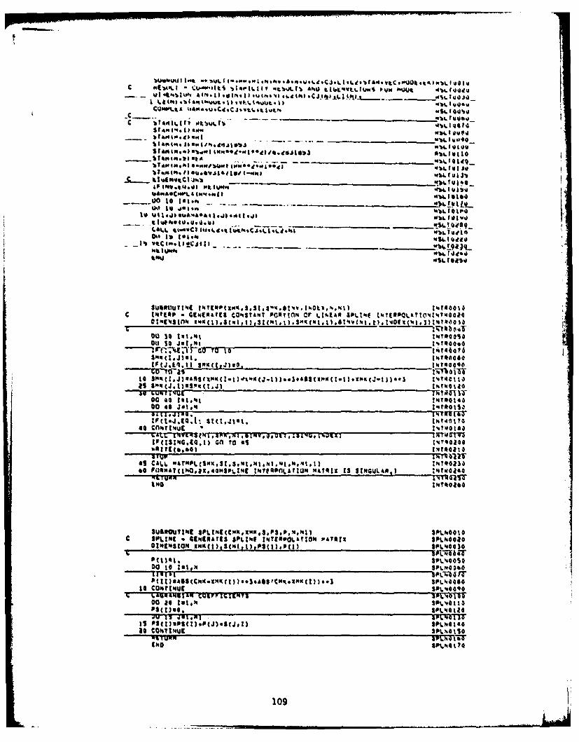
C ft4Ilt tUAI~t 'bAIIAIY'i~~A1b At SjkVt.ttUS$ 11wMJt 4t.fgiituUt otwopl Atm _1001,)o~a.1 ~h C~JJjt
WbL 101*
%144 t. is amwI.IlJ N%4. 10 4)
bto ft.ses.l sakeJAuaeI.mf
'ASavo6Ce4L 4 40440 to 110*
___________________________ 1-Stme IW 4 I E~
c MItme - GENC(Nfts CaptsfA4 PCSTMMl cr Lt-m SPs.IN~ IP0~t~Z*fG~
as S(je.1 spcloj1 v,1,04
00 40 IM ITOO*140
00 4 JIQ I' 141 40111
IacSp0.Co t 1n o .Wq*ObAI?~ec0) 9etQI,
40 Cno'UC
65CAt.IANCSN. .1.SN.1N.N..I GNTTOI3O
60 P~oIAeTayl(Ig2..owsP.NI INTIRPOLAT1ON MATRIX 1S 3tRGUL4011 ) 1WO4
C SPICN 0 egMNIS SPLIt.I INTERPOLAT1N PAhral SPLO0O
00 to :8105PNOa418161 OLN-4 4
Pt~tUAS(CM(.EM(I )...A6CM~KPSC1V..3SPL444SO10 Cuwotmwuc -SPLNOO6O0
ps(oo.SOL'40atl04w 11 140MIN SPEM
IS 's(I~m'g(Z)OP(J).8(J.) SPLO4Ga.COO,:'ut SPL'.S1150
109
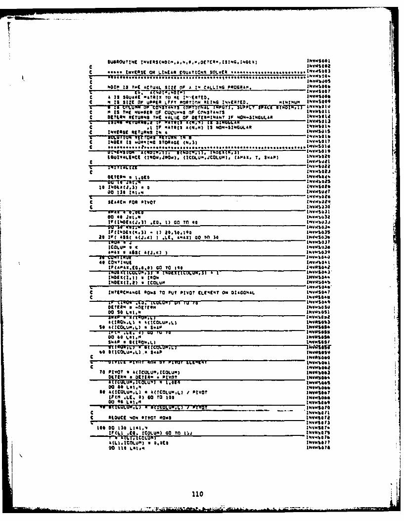
C *0000 INVERSE ORn LUhIA. 14UA?1CR SOLVER.....,.,, 0 ,.,I4 .10
c 13 ?W ACTUAL ~ w*I CLIGPOE
F. f .1 (I.50 IM IWSIG
C N. 1S StZt OIf UPPER OFT' mcrtnm PL!IG I',IMI0. "!IN"UP ItVO9v, W LIPILURN OF CON3YT0NTV AOTQ~tiP1Y7U~Sf ITWT IV681C 'I IS ?HE 'su"eIl of CUL-UM'S (If cmkI.SAa.t1 i"NWI Ic 01716'. RETURNS THC wVL'IC OF 0iCPNI'.lkhr If NON.SIN6UL.Al I#4V POW
C . IF wTag I csM is NON.S1'GULAR IIIc IN4W9115 RETUR1NS I' a IsMQI
S 064C.:U I5RING STRAE 00 INV .0 01
11O UIW ALINcI ti la0 I J 0w ) IC LU llJCOLUN) # (A "&,# T o SWAP) 1N vm s a t
% &R& F 1AuI i u~s.u~j.&.IQKN Ih~VW5022
C C I -7 1 1 I"Voib "l
6I'.0'cj.3) a a *V*100 130 ta.1' I'sv'.lQu7
INVNS431
go 46 Ja..ItiIOU32tICZNO(xj.l *EQ, 1) cOl T 40 toevotu3JJ
£Fc.:;sgco.) * 1)1.1.9 INVwS03S86 IFI ( W IJ.) I M.E 4"AX) G0 TOI 36 INVNS030
IT*O 4 IINVWS437ICOZU" - 4 I'sVMS9je&AK~ a AW5 &(jog) 1IhvmQ3*a! RgU* JINVOI40
40 CO'.'IWUt IINW.'10*LkFa~a.G ~ t, o TO too 114VRS441
W INC4~cCLJuN,3 6 1 INVWS4J3NOt(.U a 0w INVUS44%p.Eal)aICOL.Ul IlV~sI4o*
c ~INVOS440,.. .C INTARCMa4GI6 SOWS TO OUT PIVOT tLE'('sT om DIAGONAL 144VWS067aC INIVOS$0
Ol1l Mu -Of 1okoo G T T INVWkbOI,
Dou s: 4.910*4 INVWQS8
A(IA0IAVLI 4 IA(ICOiLuMOL) P~31S0 M(COLUP.L) a $MAO IN.W11S4
o MICOLuo.l. a SOAP I#.voseS9
C ItV~boe70 PIVOT a A(IcOLUNq.ICOLUm) Il's1b63
AMIULUMMJOLU.3 Hon 1.5 tmvm60500 60 Lai*" I'4v'oluoef
40 W(CIJLuN.LI 4 W(COLUN~A) t PIVOT ift.VIsoo00 4 .96 0) so T0 too 1IR60 I00 0 L81,14 IsVIO*,
C v INVN%410
c atouCt '.0' OIYCT RawS I'.vS@ 7% INiISO 73
lot D0 136 L101.4. INVNSO 76tFcLt sta. IcuLum) GO TO iii INYVbO 76&T b .Ct1 * **lN INV"%Q ?b
00 110 Lal.' Ibw0?
110
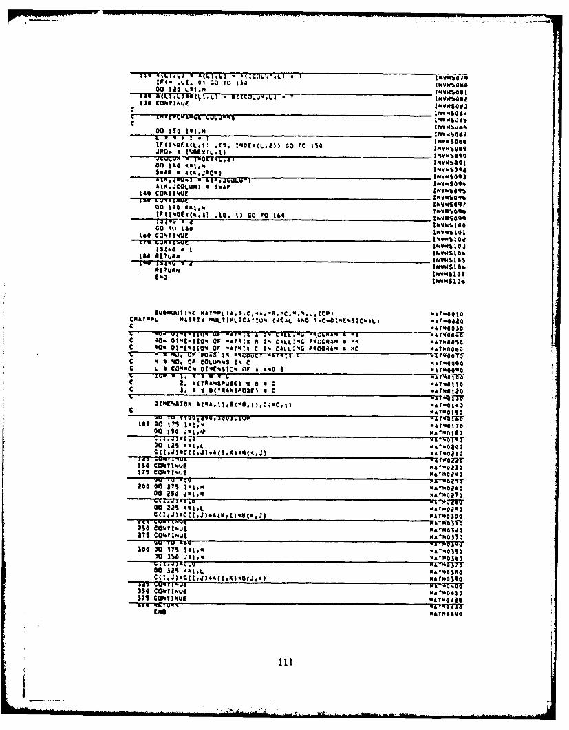
tT.I * * CIW LIf(" ILI1, 0) Go To t3000 tic Lat.m 4w101
LevG! UI IL)(1.1 - B(Ir'.LvU'.L) a T ~,~ulie CON?;,.",:v~oe
00 110 tot." Nwb~
tF(FtXVEL.I J1. 1411(Loil) GO To MS
SNAP a 4014JO011) rvSq
a(KojCOLuM) a SWAP 1vb9140 COft~4'Uf zIsV"4OO.lav CONF~IRMU
tftVwSoqe00 170 neai, INV*%**%IIFIW091(kol) .fo. 1) GO TO 164 16vmS.9q
&aimu - CI~viblOOGo TOl 130 INVW1010I%so CO~r%.ut 14WdSZO*Irv huqfiut IWV.4b10j
Ms~ a I IhvfSIO4
I PO l15113
CftafMPI. MATRIX MULThII.CATUM VCAL 4NO T.G.OIMEWSLO0MAL) mroa
T. Ud oI:;:uIn: UP :ATg Pau 140 a 04e. wi3C '.0. 01 toW or Are1 A 1% C&LLIG 040G4,1" a uAMAMOSC 40%01 OTWIION OR 4"Etx C 14 CALLING6 PSOO4Am 3 MC "Ar"6404,
C 4 a 400 OR COLUMNWS 1% C may"COSOC L 4 COMMNw 01"(%SKQW Of A A140 6 wArMOO60
C 2. A(T044SOU8() 'vI a C "AT,@tlOaC 3.A (TRAMSP0SI) a C MATWOtio
oZM(%Stom At"AI1).gcW.I )OCt"Co. 1M A?'S140C MANOISO
to0 00 173 tat.% aii700 ISO J21.40ATfl
00 gas OR1,L " At"0144C4 CNJa~ 1 .)A1N 1AqJ WSWOI
ISO CONTINUE A%03
17 5 CONTINUE a M~
300 00 273 131."0)0 30 J4liMAT430
00 ail matL "'tmO204
ISO CONTlINUEMGL37 CONTIN.UE ai~l30uv TVU~ 49QT3
'40 OTNUATMOI4IO
3IS CNTINE NA"111OgASUN" "46I
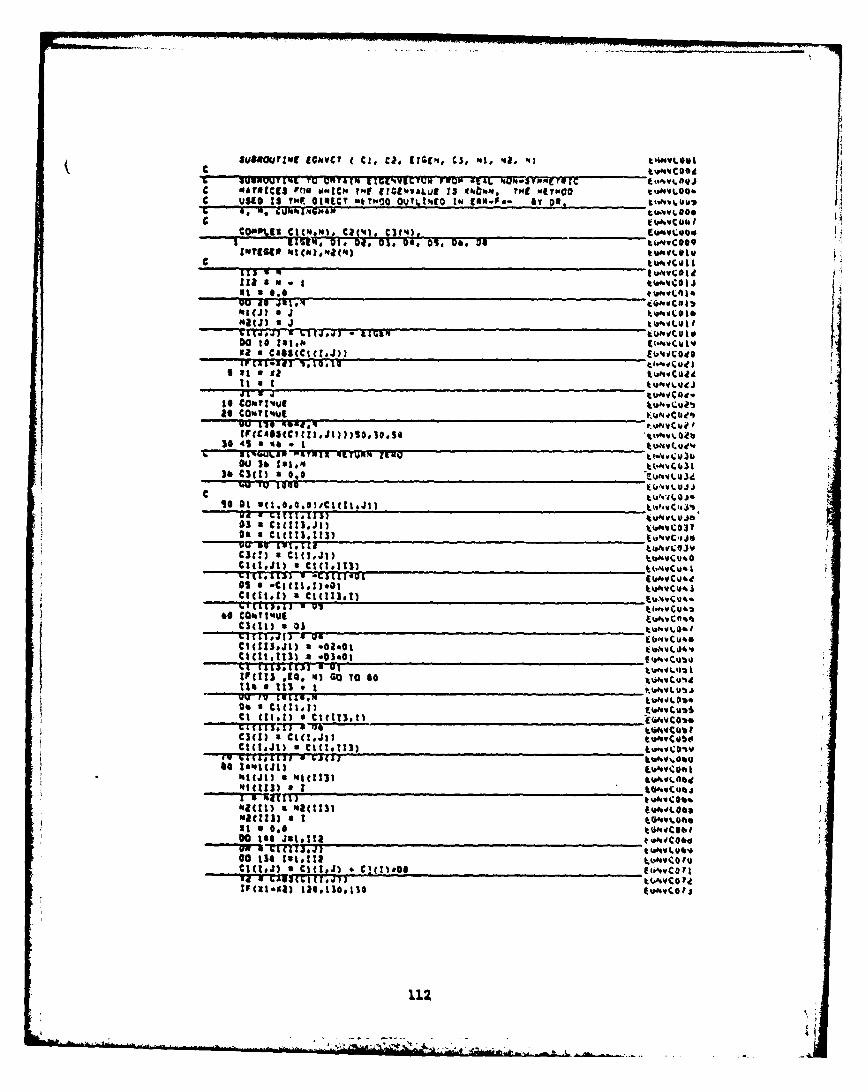
IufueaO~vc~ 1G3.vcy Cl, C,?, £?1414 C3, "to '8, '4) i.w.,s
308UUWTI'4 TOU gTraIN £I1('4WUTUMI FwI O &.'g,.yp'(g evPPlgNNtACES PeIN womICA. TueF CIE?'VhALUE 13 ghbm.. T141 IrouCD u'I
C SI uu 10s C~ tmIEC, fatw40 ourt'i~to iN csM.F. Sy OR,S Aq . b'tI4NN~..~
[far 63 or'MI') C e) .4 C 0
1138 3.D.0. h 4i~~ti@
It a 6.0coiIF [At-II]T to-tl c W I
I0tO tauft((",voti
as CO'.??vqjltdu4M
M0 4 1 2 40 4" II 11 vo I ,34 4S a 46 - I~~JY k uva.g 4,
36 3.JI)w II3I3 .. cj
CSSIi aa I13t
rr1tlli a 2~4CIM?3) as0.1~aA..'5
0.~~ -0~ca300
111k) a j113
'43(113)l 8 1 04v u
hI3() a W(13)
GICT046JJ
GIC11112
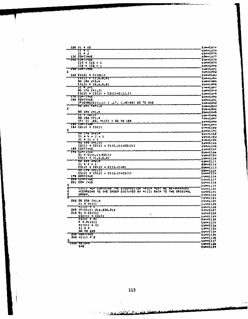
Ji a 4 t.(ayvco fpslid COA'IrzuEtvtu1
60vI Z WE * ji*'.C0 'es
113 a.~LU kisahJcU I
C .ir I L'a'.hVtcuo
160 C3(2) a C101 tvCbej
04)M a1 MGM I"Vuh.CICJ to (0.00.0 t L oo..11j 2 k'iftVLO1.0
003 t70 tutJt tiu.vC p5C3CJI I C3CJ) I. c3t1)eCICj.,1 a'.vC 0*4
160 CONTINUE LIi'.CUV IlFCCLOS(CM0~1) ) L7. '.OIE.20) co To 202 t~~s
00 184 ajtlm
00 I182 ?*,'tf( It .0., MIC?) I Go To 184 L,,avcu40f
164 C2(J) a C3(l) 9 OftC 10u
uu e~ ilptft I a
J1 It~ * I Ee6aivC 10
01tl s c~tl,~tII iu'4vC10w(
C3(j) a cacJ) a CICJ.J3.0t E''C~
C3(J) a CunJ * CICS,1)*Cs(t) upiC I I195 CO%'4'Uz tINVILt tft
201 Cow. 0'UE *kblovc I Ic k&AaNvLI 119'- C.Jt&1 VUiv f.EhA!41 it EPLbLNVL6Tt1q-PIC MUZF StU~ MI ,.i4aWTWGr - t(.VIc LCcensiIFG TO~ THE OROER OICTATCO SY Mitt) SACK TO 134( ORMONAL tVMC 09013, Ei4ftc1U
202 00 230 Istem 1. .1
tIv( I 4eb
210 01 aU M C3(?I)12
Xci V. M C() LAi'9WC131
NICIJ) a ItL~~vl3It a K ~Av,3w O 0 S 20fumvC I34bG~ URI4J1UL IVamYC131
260 Ml3 M a a E~avcIjbC tft^VCIJ?
113
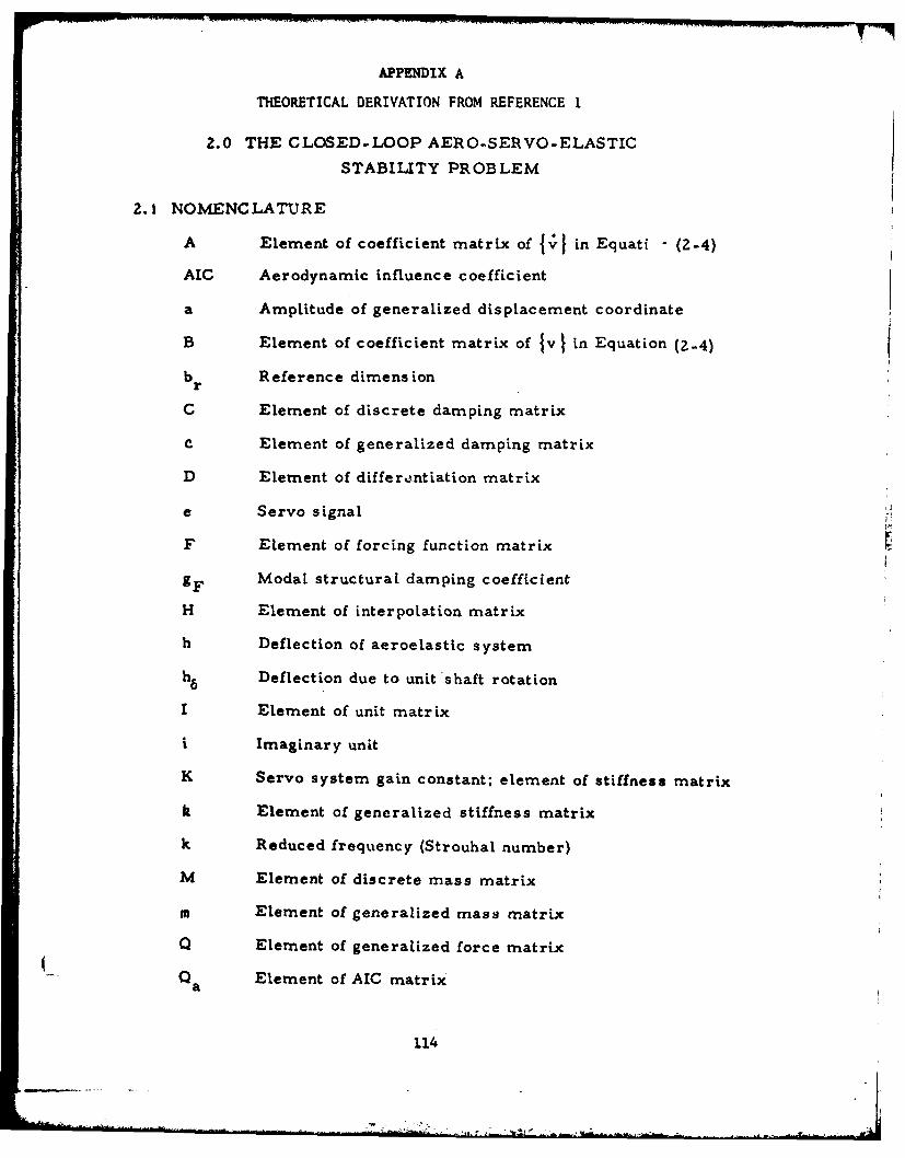
APPENDIX A
THEORETICAL DERIVATION FROM REFERENCE 1
Z.0 THE CLOSED-LOOP AERO-SERVO-ELASTIC
STABILITY PROBLEM
2.1 NOMENCLATURE
A Element of coefficient matrix of Jv] in Equati (2-4)
AIC Aerodynamic influence coefficient
a Amplitude of generalized displacement coordinate
B Element of coefficient matrix of 1v I in Equation (2-4)
b Reference dimension
C Element of discrete damping matrix
C Element of generalized damping matrix
D Element of differe ntiation matrix
e Servo signal
F Element of forcing function matrix
gF Modal structural damping coefficient
H Element of interpolation matrix
h Deflection of aeroelastic system
h6 Deflection due to unit shaft rotation
I Element of unit matrix
i Imaginary unit
K Servo system gain constant; element of stiffness matrix
k Element of generalized stiffness matrix
k Reduced frequency (Strouhal number)
M Element of discrete mass matrix
m Element of generalized mass matrix
Q Element of generalized force matrix
- a Element of AIC matrix
114
.... : " '-- .... . ... .... . ..... -...... ' ' '" **, ,' ." --'-- :. .""-%, " .. ,,,. " -'.* "" ................................".......,--
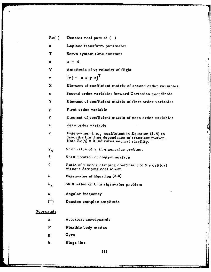
Re( ) Denotes real part of ( )
s Laplace transform parameter
T Servo system time constant
U U =
V Amplitude of v; velocity of flight
V IvI= Lu x y zi T
X Element of coefficient matrix of second order variables
x Second order variable; forward Cartesian coordinate
Y Element of coefficient matrix of first order variables
y First order variable
Z Element of coefficient matrix of zero order variables
z Zero order variable
y Eigenvalue, i. e., coefficient in Equation (2-5) todescribe the time dependence of transient motion.Note Re(y) = 0 indicates neutral stability.
YO Shift value of y in eigenvalue problem
6 Shaft rotation of control surface
Ratio of viscous damping coefficient to the criticalviscous damping coefficient
X Eigenvalue of Equation (2-8)
X 0 Shift value of k in eigenvalue problem
WAngular frequency
(-) Denotes complex amplitude
Subscripts
a Actuator; aerodynamic
F Flexible body motion
g Gyro
h Hinge Line
115
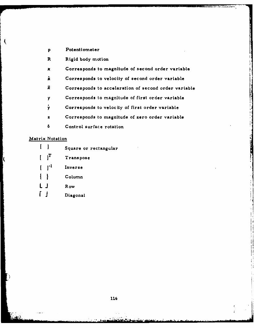
p Potentiometer
R Rigid body motion
x Corresponds to magnitude of second order variable
it Corresponds to velocity of second order variable
x Corresponds to acceleration of second order variable
y Corresponds to magnitude of first order variable
y Corresponds to velocity of first order variable
z Corresponds to magnitude of zero order variable
6 Control surface rotation
Matrix Notation
[ I Square or rectangular
[IT Transpose
( ]-I Inverse
Column
L J Row
r i Diagonal
11
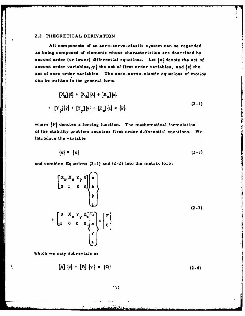
2.2 THEORETICAL DERIVATION
All components of an aero-servo-elastic system can be regarded
as being composed of elements whose characteristics are described by
second order (or lower) differential equations. Let lxj denote the set of
second order variablesfyi the set of first order variables, and faz the
set of zero order variables. The aero-servo-elastic equations of motion
can be written in the general form
- I [X~ROM + [X)l + PCX:IIxi
+ (YPIJ} + (Yyl]lI + zJ = P (2-)
where JFJ denotes a forcing function. The mathematical formulation
of the stability problem requires first order differential equations. We
introduce the variable
lul 1*1 (=-2)
and combine Equations (2-1) and (Z-2) into the matrix form
(2-3)
+L0 x Yy Z (F)10 0 0] x 0
Y t' Iwhich we may abbreviate as
=-1(A) Ivi +(B lvB I I (2-4)
117
U. 7
% ., ' :,=. =u . .. . . ........ ... .... .... * ",' ,,, -. L - '. * . , : ; . , __ , - . .. . . . J
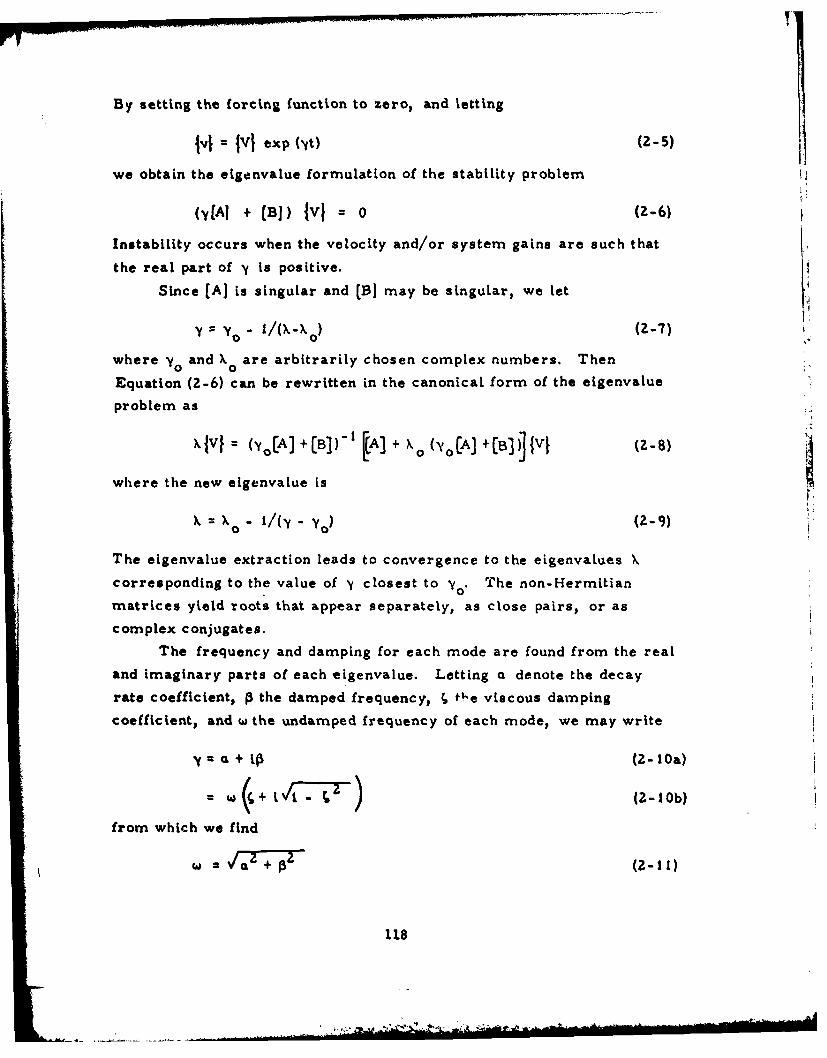
By setting the forcing function to zero, and letting
lvi = VI exp (NtO (2-5)
we obtain the eigenvalue formulation of the stability problem
(-y[Aj + [B]) iV[ = 0 (2-6)
Instability occurs when the velocity and/or system gains are such that
the real part of y is positive.
Since [A] is singular and [] may be singular, we let
YO . i/(X-X 0 ) (2-7)
where y and X are arbitrarily chosen complex numbers. Then0 0
Equation (2-6) can be rewritten in the canonical form of the eigenvalue
problem as
Xlvi = (YoCA) +[B])' [A] + 'o (LAI +(B3 v (Z-8)
where the new eigenvalue is
X= X l/(,,, - yo) (Z-9)
The eigenvalue extraction leads to convergence to the eigenvahues X
corresponding to the value of y closest to y . The non-Hermitian
matrices yield roots that appear separately, as close pairs, or as
complex conjugates.
The frequency and damping for each mode are found from the real
and imaginary parts of each eigenvalue. Letting a denote the decay
rate coefficient, P the damped frequency, ; t l-e viscous damping
coefficient, and w the undamped frequency of each mode, we may write
CL + t3 (2-l Oa)
= + (2-lOb)
from which we find
W 2IT+ = (2-11)
118
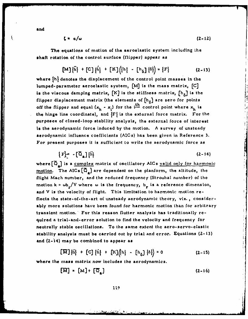
and
,a/l (2-12)
The equations of motion of the aeroelastic system including Lhe
shaft rotation of the control surface (flipper) appear as
[M)t1; + [C) l a + [K)(hI - [h6j 161) = IFI (2-13)
where (hi denotes the displacement of the control point masses in the
lumped-parameter aeroelastic system, (M] is the mass matrix, CC]
is the viscous damping matrix, [K] is the stiffness matrix, [h 6) is the
flipper displacement matrix (the elements of [h,] are zero for points
off the flipper and equal (xh - x,) for the i- h control point where x h isthe hinge line coordinate), and (Fl is the external force matrix. For the
purposes of closed-loop stability analysis, the external force of interest
is the aerodynamic force induced by the motion. A survey of unsteady
aerodynamic influence coefficients (AICs) has been given in Reference 3.
For present purposes it is sufficient to write the aerodynamic force as
jF}-= -[al] {i~ (2-14)
where [aa) is a complex matrix of oscillatory AICs valid only for harmonic
motion. The AICs [ a] are dependent on the planform, the altitude, the
flight Mach number, and the reduced frequency (Strouhal number) of the
motion k = wb r/V where wo is the frequency, br is a reference dimension,
and V is the velocity of flight. This limitation to harmonic motion re-
flects the state-of-the-art of unsteady aerodynamic theory, viz. , consider-
ably more solutions have been found for harmonic motion than for arbitrary
transient motion. For this reason flutter analysis has traditionally re-
quired a trial-and-error solution to find the velocity and frequency for
neutrally stable oscillations. To the same extent the aero-servo-elastic
stability analysis must be carried out by trial and error. Equations (2-13)
and (2-14) may be combined to appear as
[lil + c) fI I + (<K)hl - ChG) 161) 0 2-15)
where the mass matrix now Includes the aerodynamics.
[X)~ •CM]> [n (+-16)
11.9
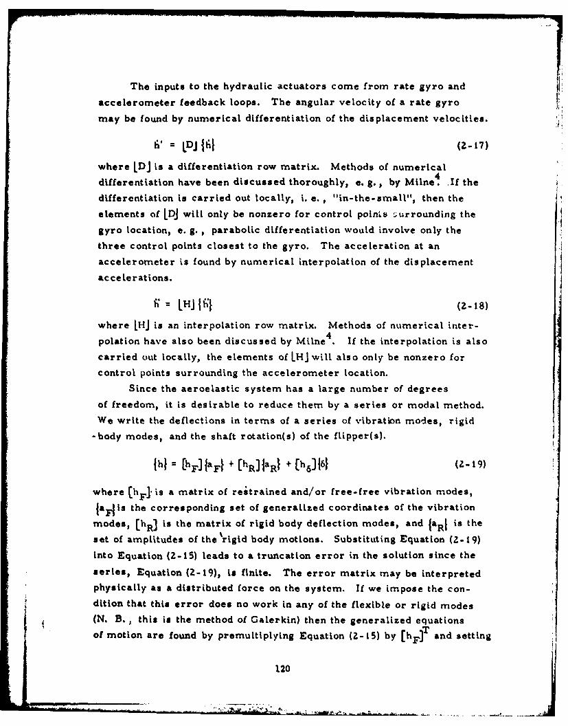
The inputs to the hydraulic actuators come from rate gyro and
accelerometer feedback loops. The angular velocity of a rate gyro
may be found by numerical differentiation of the displacement velocities.
L DJ {} (2-17)
where IDJ is a differentiation row matrix. Methods of numerical
differentiation have been discussed thoroughly, e. g., by Milne. If the
differentiation Is carried out locally, i. e. , "in-the-small", then the
elements of LDJ will only be nonzero for control points .urrounding the
gyro location, e. g., parabolic differentiation would involve only the
three control points closest to the gyro. The acceleration at an
accelerometer is found by numerical interpolation of the displacement
accelerations.
LHJ L 1J (2-18)
where IHJ is an interpolation row matrix. Methods of numerical inter-
polation have also been discussed by Milne4 . If the interpolation is also
carried out locally, the elements of lHJ will also only be nonzero for
control points surrounding the accelerometer location.
Since the aeroelastic system has a large number of degrees
of freedom, it is desirable to reduce them by a series or modal method.
We write the deflections in terms of a series of vibration modes, rigid
-body modes, and the shaft rotation(s) of the flipper(s).
ihi = [hF]a.1 + [hR)IaR} + (h)11 (Z-19)
where (hF. is a matrix of restrained and/or free-free vibration modes,
laFlis the corresponding set of generalized coordinates of the vibration
modes, [hR] is the matrix of rigid body deflection modes, and faRl is the
set of amplitudes of the% rigid body motions. Substituting Equation (2-19)
into Equation (2-15) leads to a truncation error in the solution since the
series, Equation (2-19), is finite. The error matrix may be interpreted
physically as a distributed force on the system. If we impose the con-
dition that this error does no work in any of the flexible or rigid modes
(N. B. P this is the method of Galerkin) then the generalized equationsT
of motion are found by premultlplying Equation (Z-15) by [hF). and setting
120
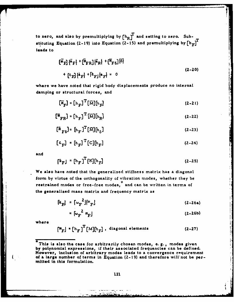
T7to zero, and also by premultiplying by ChR]T and setting to zero. Sub-
stituting Equation (Z-19) into Equation (2-15) and premultiplying by (hFJ
leads to
(IF{FI1 +CMFR]IIR +L7F6]l'
(2-20)+ (CiJ{&F4 +rFJIaFI- 0
where we have noted that rigid body displacements produce no internal
damping or structural forces, and
[ ( hF)T [M][hF] (2-21)
[ MR E ChF) T ]a) (2-22)
[rF6)- [hFEjT R][h6 ] (2-23)
(C F = (hF)T[C) hF] (2-24)
and
[kFJ P [hF] [K][h ] (2-25)
We also have noted that the generalized stiffness matrix has a diagonal
form by virtue of the orthogonality of vibration modes, whether they be
restrained modes or free-free modes, and can be written in terms of
the generalized mass matrix and frequency matrix as
= F mFJ (2-26b)where w Fj z [h F ]T (M ] [hFl , diagonal elements (2-27)
This is also the case for arbitrarily chosen modes, e. g., modes given
by polynomial expressions, if their associated frequencies can be defined.However, inclusion of arbitrary modes leads to a convergence requirement
( of a large number of terms in Equation (2-19) and therefore willnot be per-mitted in this formulation.
121
- -- . , . . ;- - - *.-.: ;. - .- .
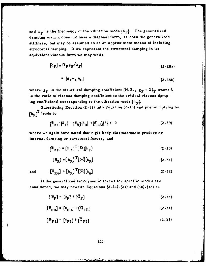
and w F is the frequency of the vibration mode 1hFI. The generalized
damping matrix does not have a diagonal form, as does the generalized
stiffness, but may be assumed so as an approximate means of including
structural damping. If we represent the structural damping in its
equivalent viscous form we may write
(CFJ - fhgF/W A(-2a
-g e F Im~J (2-28b)
where gis the structural damping coefficient (N. B. , 2 ' 2 'Fwhere T
Is the ratio of viscous damping coefficient to the critical viscous damp-
ing coefficient) corresponding to the vibration mode 1hF[.
Substituting Equation (2-19) into Equation (2-15) and premultiplying byT
(hR] leads to
[RFIFFI PTRIRI +10-- 6 14 = 0 (2-29)
where we again have noted that rigid body displacements produce no
internal damping or structural forces, and
tMR F] Ch RhIT [ MXhFA (2-30)
[6R] (hR] TC M] hRI 231
and [M R61 Ch R)IT[Fj] [h 6J (2-32)
If the generalized aerodynamic forces for specific modes are
considered, we may rewrite Equations (2-2l)-(23) and (30)-(32) as
IMF]J + £PF] (2-33)
("FRI)= (mFR) + [""FRI 2-4
(A F63 2 EmF6) + t[5F6) 235
122
*MW '.t~g
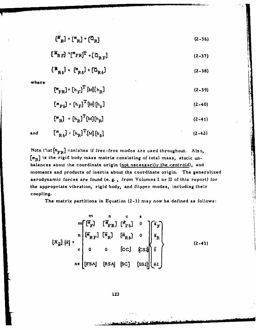
[RI = ("R] + [ZR] (2-36)
[7RF] =["FRIT +[ 5RF (2)-37) !
[R6 1 = (M61 + MR61 (2-38)
where (FRI [hF]T [M][hR) (Z-39)
(mF ChF3J CM3 [h] (2-40)
T('R ] [hRT [M]hRI (2-41)
and [mR6 C R [hs] (2-42)
Note t'atCmFR) vanishes if frec-frce modes are used throughout. Also,
(mR] is the rigid body mass matrix consisting of total mass, static un-
balances about the coordinate origin (not necessarily the centroid), and
moments and products of inertia about the coordinate origin. The generalized
aerodynamic forces are found (e. g. , from Volumes I or II of this report) for
the appropriate vibration, rigid body, and flipper modes, including their
coupling.
The matrix partitions in Equation (2-3) may now be defined as follows:
m n c s
"-' 'FR] ('FF6] 0 &F
Vx] fIR n (2-43)0 0 rccJ Cs?] g
AS LFsAJ IRSAJ (SC] [ss lz
123
t4 .....
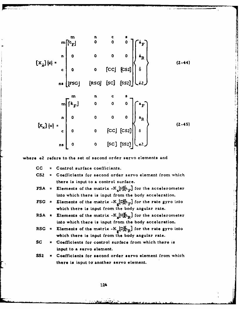
mn n c s
Mc.FJ 0 0 0 a,
n 0 0 0 0 aR[x ] } -- ,(2-44)
c o o rccJ zsz]
n, ,LFSGJ RSGJ [sc2]52] .i2j
m n C s
mrJ o 0 0 0 a
n 0 0 0 0 aR
I] x, = I 6 (Z-45)c 0o rccj [cs2] 6
ns 0 [c] (ss2] e?.L
where eZ refers to the set of second order servo elements and
CC = Control surface coefficients.
CSZ = Coefficients for second order servo element from which
there is input to a control surface.
FSA = Elements of the matrix -KaIHJhF ] for the accelerometer
into which there is input from the body acceleration.
FSG Elements of the matrix -KgL DJhF] for the rate gyro into
which there is input from the body angular rate.
RSA Elements of the matrix -KaLHJ(hR] for the accelerometer
into which there is input from the body acceleration.
RSG = Elements of the matrix -KgLDJ IR for the rate gyro into
which there is input from the body angular rate.
SC z Coefficients for control surface from which there is
input to a servo element.
SS2 Coefficients for second order servo element from which
there is input to another servo element.
1114
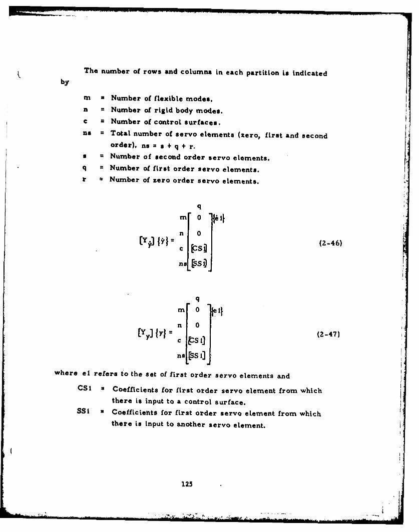
The number of rows and columns in each partition is indicatedby
m = Number of flexible modes.
n = Number of rigid body modes.c = Number of control surfaces.us = Total number of servo elements (zero, first and second
order), ns = s + q + r.s = Number of second order servo elements.q = Number of first order servo elements.r = Number of zero order servo elements.
qm 0 'i
n 0
(2-46)
nns s
q
mm 0 1n 0(yr] {r (2-47)
nal reSSI
where el refers to the set of first order servo elements and
CSI = Coefficients for first order servo element from whichthere is input to a control surface.
SSI = Coefficients for first order servo element from whichthere is input to another servo element.
125
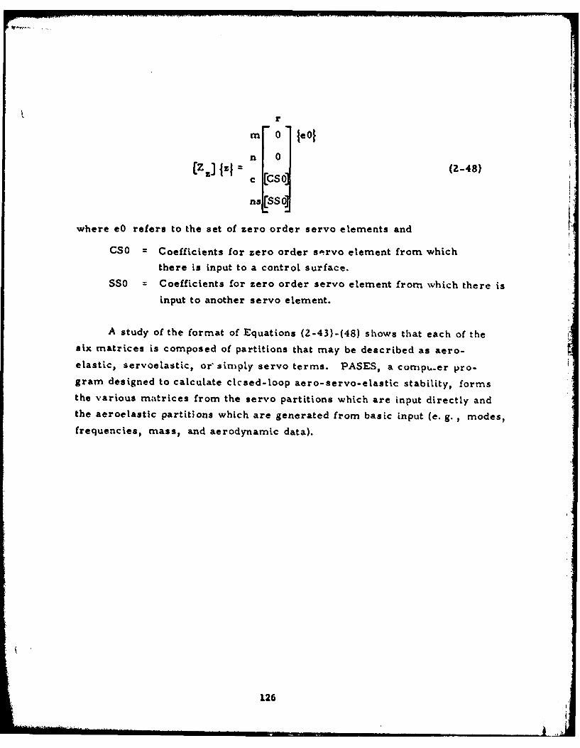
rm 0 JeO
n 0(Z] Izl (C s (2-48)
ns (SSO0J
where eO refers to the set of zero order servo elements and
CSO = Coefficients for zero order s',rvo element from which
there is input to a control surface.SSO = Coefficients for zero order servo element from which there is
input to another servo element.
A study of the format of Equations (2-43)-(48) shows that each of the
six matrices is composed of partitions that may be described as aero-
elastic, servoelastic, or'simply servo terms. PASES, a cornpu.er pro-
gram designed to calculate clcsed-loop aero-servo-elastic stability, formsthe various matrices from the servo partitions which are input directly and
the aeroelastic partitions which are generated from basic input (e. g. , modes,
frequencies, mass, and aerodynamic data).
126
iiiiiii iii
APPENDIX B
AN APPLICATION OF PROGRAM MPASES
TO A
TYPICAL AIR-TO-AIR MISSILE
Introduction
The computer program MPASES developed in this report used the same
example problem to demonstrate its usage as had been used in the original
version of the program. That example of an air-to-air missile was not a
very practical one to the extent that it had no wing, the weight of the
aft end of the fuselage was assumed to oscillate with the control surface
(flipper), and there was only a single (rate-gyro) feedback loop. In
addition, the example used an incorrect transfer function for the actuator
[Eq. (78) should have read 6/e 3 - Ka/s(Tas + 1)].
The new example studied here is still somewhat idealized but is more
practical to the extent that a wing, with its attendant aerodynamic loads,
is added, and a light-weight dynamically balanced flipper with bending and
torsion degrees of freedom is considered separately from the body. A more
realistic servo system is also considered with three feedback loops, a rate
feedback loop (with a rate-gyro as before), and attitude and acceleration
feedback loops.
In addition to being a more practical problem which demonstrates a
more general use of Program MPASES, the sample also illustrates certain
peripheral aspects of the problem. One is the calculation of a coupled
mass matrix for the flipper. Another is the calculation of the wing and
127
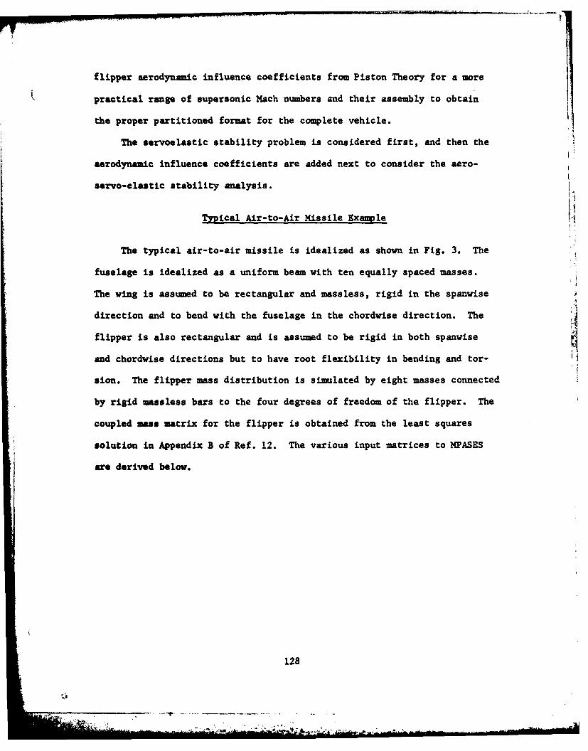
flipper aerodynamic influence coefficients from Piston Theory for a more
practical range of supersonic Mach nmbers and their assembly to obtain
the proper partitioned format for the complete vehicle.
The servoelastic stability problem is considered first, and then the
aerodynamic influence coefficients are added next to consider the aero-
servo-elastic stability analysis.
Typical Air-to-Air Missile Example
The typical air-to-air missile is idealized as shown in Fig. 3. The
fuselage is idealized as a uniform beam with ten equally spaced masses.
The wing is assumed to be rectangular and massless, rigid in the spanwise
direction and to bend with the fuselage in the chordvise direction. The
flipper is also rectangular and is assumed to be rigid in both spanwise
and chordvise directions but to have root flexibility in bending and tor- H
sion. The flipper mass distribution is simulated by eight masses connected
by rigid uassless bars to the four degrees of freedom of the flipper. The
coupled mass matrix for the flipper is obtained from the least squares
solution in Appendix B of Ref. 12. The various input matrices to NPASES
are derived below.
128
- "Mod
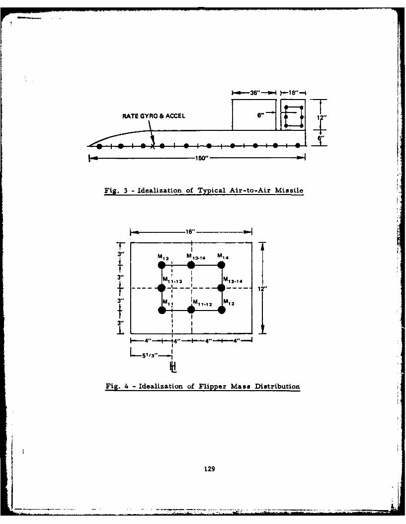
RATE GYRO & ACCEL 6"
S150"
Fig. 3 -Idealization of Typical Air-to-Air Missile
3" M13 13-14 14
3" Ml1. 13 1 M12.14
. .2I
3" M12, A1.12 1
II
3I II:,
L-51/3"-.
Fig. 4 -Idealization of Flipper Mass Distribution
129
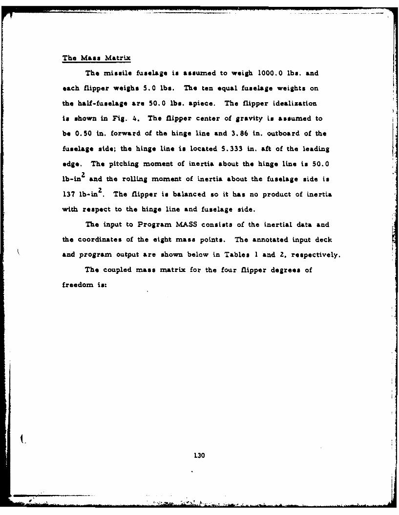
The Mass Matrix
The missile fuselage is assumed to weigh 1000.0 lbs. and
each flipper weighs 5.0 lbs. The ten equal fuselage weights on
the half-fuselage are 50.0 lbs. apiece. The flipper idealization
is shown in Fig. 4. The flipper center of gravity in assumed to
be 0.50 in. forward of the hinge line and 3.86 in. outboard of the
fuselage side; the hinge line is located 5. 333 in. aft of the leading
edge. The pitching moment of inertia about the hinge line is 50.0
lb-inZ and the rolling moment of inertia about the fuselage side is
137 lb-in2 . The flipper is balanced so it has no product of inertia
with respect to the hinge line and fuselage side.
The input to Program MASS consists of the inertial data and
the coordinates of the eight mass points. The annotated input deck
and program output are shown below in Tables 1 and 2, respectively.
The coupled mass matrix for the four flipper degrees of
freedom is:
130
"p#i
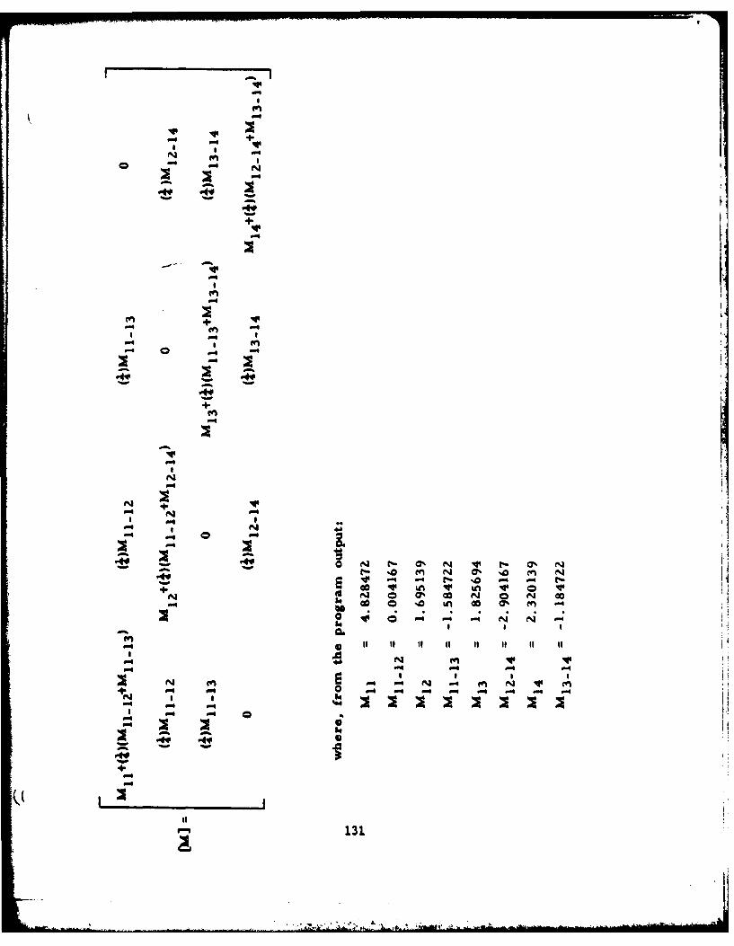
m V.
4.4
4- it It 11 1-m
P- P
4.4
113

Table 1 Inpuit Cards for Program MASS
C TITLE ANO SUBTITLE CARDSLEAST SQUARES MASS MATRIX
--...MASS tLEMENTS FOR TYPICAL AIHT-AI-MISSLE............___C NUMBER OF STktPS
I_- NUMBER OL-MASS(L.......... ___________
C INERTIAL PROPERTIES
C MASS POINT COORDINATES1*333333333 3.0 -2.b66666667 3.0 -696666664 3.0lo.J33333333 b.O_____ 1.333*33333 9.0.. Tbbq66eb%6 *,4___
-60660066667 9.0 -2*66666.667 90
Table 2 - Ouxtpuxt from Program MASS
LkA1I is.U~mis "AS MiTOIAmA&S KL&AWNS FOR TYPICAL. AIN-TO-AIkM ISSILt
NtUI4Ut Of "Asbsby %?Ri
I~ it S 10 ' i ItIt t3 1 l IS 16 It t9 40
lQrAL "ASb A 2 *S0044409%.01A utNuALAhCt. 0A DAN N e"000OG'fI
___________I 1l UWALANCL %Y *am a .IvituoaouluV Muf~tm W IntwitA I %US I U .%0900090Lt.04JA NUPIiNT U1, £NC0ILA I Wuu A. R *.31 00009t.0
.MuCTOF IMCAfIA I bSUO AT a 0g
At 11 *&sjjjjjjP.01 It 11 .3UOGUOO(.10it__ _______ 21 iiU .'el~eftaOJc.G It .31090a0 .*3fl.- -ju I'
At 3) *-.bs6e',e..I0. I J0000000001 1'@
A( 61 *.A1JJjjjk'Ui It 41 a *[email protected] *-A( SI -. .JJJJJ~jf.OIj Y1 S) a VOGQOOGO&-Gt
At 61 a .&0eataikeGl It 61 a .64000009C.014t 71 *-eefel.I it ?I *.usoovU0164
______ __________ _At .1 .aaIaCQ t a) .400Ou00066I041
itabIAb A'.U *1LUUN4JARI NAISS G&UJPtl IN ArNICtb -.
S040001001______ *~J~O~6 .1400k4 *IQOOUWGi *Ig1uut' .IJ0alvuc.41 .loG00i)E.OL .10, A-O
*[email protected] *3iiJjit.@I *.a.ab&0k -. 0*006lh.4OI *1JJ3j~ito *Ijjj~jt*0I*e1~ ~ tQ6193400t.02 .3J080111.@1 *3VIGuuvuot. *Ju.&904004tLI*'.l~uPG *AOJU.0I
0. ~.Ou1jiefta *.O0000.41 -. 0ui('* *OG6O.h **0O'I .O00t.@l
.000@049*61 *1S0Ooavk'I -. 000101
**e~ta~*O~..%'G4Gk*G1A.eI00u~e0 461i00iast.0
*.*OtUI*E .l~0I~.~uZNA"b MAINIA
** I6*ftft*3k-G4
132
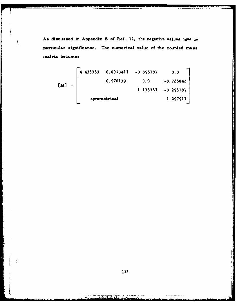
As discussed in Appendix B of Ref. 12, the negative values have no
particular significance. The numerical value of the coupled mass
matrix becomes
4.433333 0.0010417 -0.396181 0.0
0.970139 0.0 -0.726042
1. 133333 -0. 296181
symnmetrical 1. 297917
133
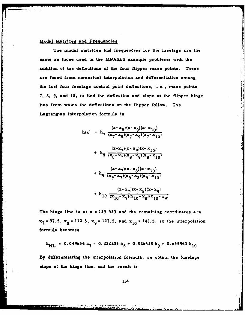
Modal Matrices and Frequencies
The modal matrices and frequencies for the fuselage are the
same as those used in the MPASES example problem. with the '
addition of the deflections of the four flipper mass points. These
are found from numerical interpolation and differentiation among
the last four fuselage control point deflections, i. e. , mass points
7, 8, 9, and 10, to find the deflection and slope at the flipper hinge
line from which the deflections on the flipper follow. The
Lagrangian interpolation formula is
h (x) = h (i- x 8 )(x- x 9)(x- x 10 )
h~x = 7 ( 7 x".)x 7 - x 9 )("' 7 - xI 0 )
+ h8 (X-x 7 )(x- x9 )(x- x1 0 )
x8 -x 7 )(x,-x 9 ( 8- 10)
+ h 9 (x 9 - X7 )(x 9 - x 8 )(x 9 - X1 0 )
(x- x 7 )(X- x 8 )(x- x9 )+ h 10 (x 0 x7 (x 0 x ) (x1 0 -79
The hinge line is at x = 139. 333 and the remaining coordinates are
X = 97. 5, x8 = 112. 5, X = 127.5S. and xl1 0 = 142. 5, so the interpolation
formula becomes
hLa0. 049654 h7 0. 232235 h8 + 0. 526618 h9 + 0. 65 5963h
By differentiating the interpolation formula, we obtain the fuselage
slope at the hinge line, and the result is
134
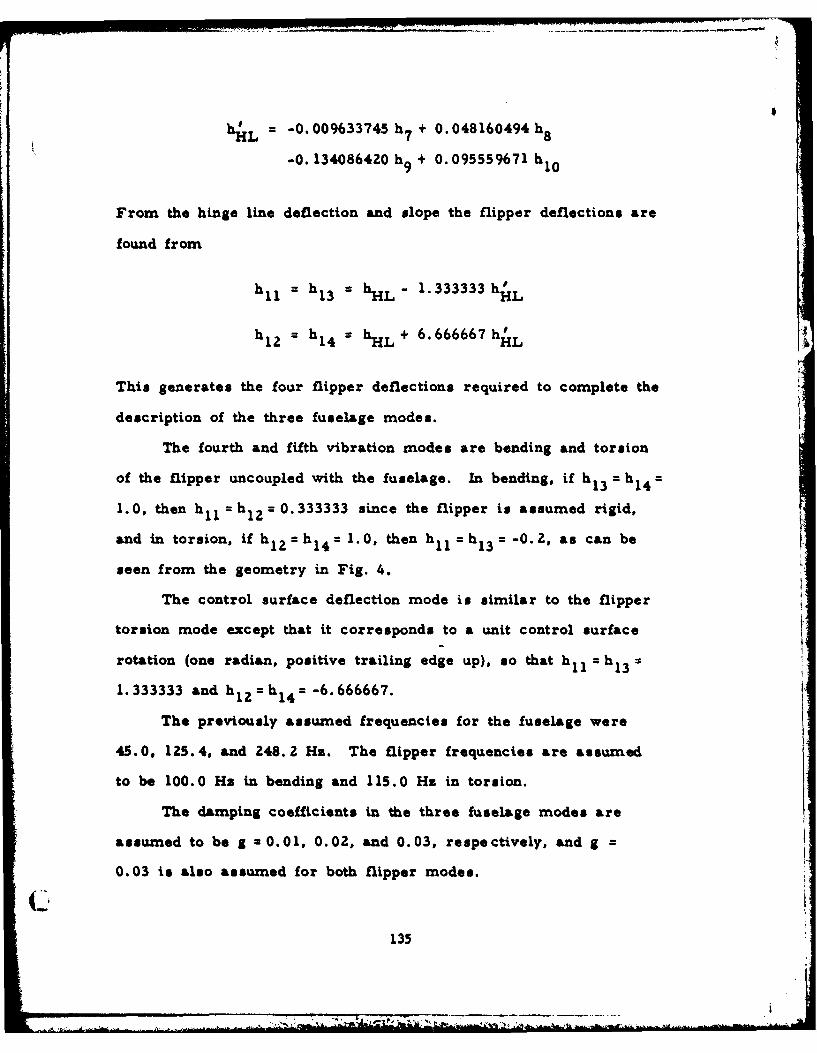
hHL = -0. 009633745 h7 + 0.048160494h 8
-0. 134086420 h9 + 0.095559671 h o
From the hinge line deflection and slope the flipper deflections are
found from
h 11= h1 3 = hHL- 1.333333 h H L
h = h h + 6. 666667 hH*12 14 = nL HL
This generates the four flipper deflections required to complete the
description of the three fuselage modes.
The fourth and fifth vibration modes are bending and torsion
of the flipper uncoupled with the fuselage. In bending, if h13 = hi 4 =
1.0, then hll =h 1 2 =0.333333 since the flipper is assumed rigid,
and in torsion, if h 1 2 =h 1 4 = 1.0, then h11 = h1 3 = -0.2, as can be
seen from the geometry in Fig. 4.
The control surface deflection mode is similar to the flipper
torsion mode except that it corresponds to a unit control surface
rotation (one radian, positive trailing edge up), so that h1 l = hi 3
1.333333 and h 1 2i=h 1 4 =-6.666667.
The previously assumed frequencies for the fuselage were
45.0, 125.4, and 248.2 Hz. The flipper frequencies are assumed
to be 100.0 Hz in bending and 115.0 Hz in torsion.
The damping coefficients in the three fuselage modes are
assumed to be g 2 0.01, 0.02, and 0.03, respectively, and g =
0.03 i also assumed for both flipper modes.
C1'135
The rigid body modes require the addition of the four flipper
mass points: four unit plunging displacements, and four x-coordinates
for pitching about the fuselage nose, x, 1 =X 1 3 138.0 and x 1 2 = 14
146.0.
136
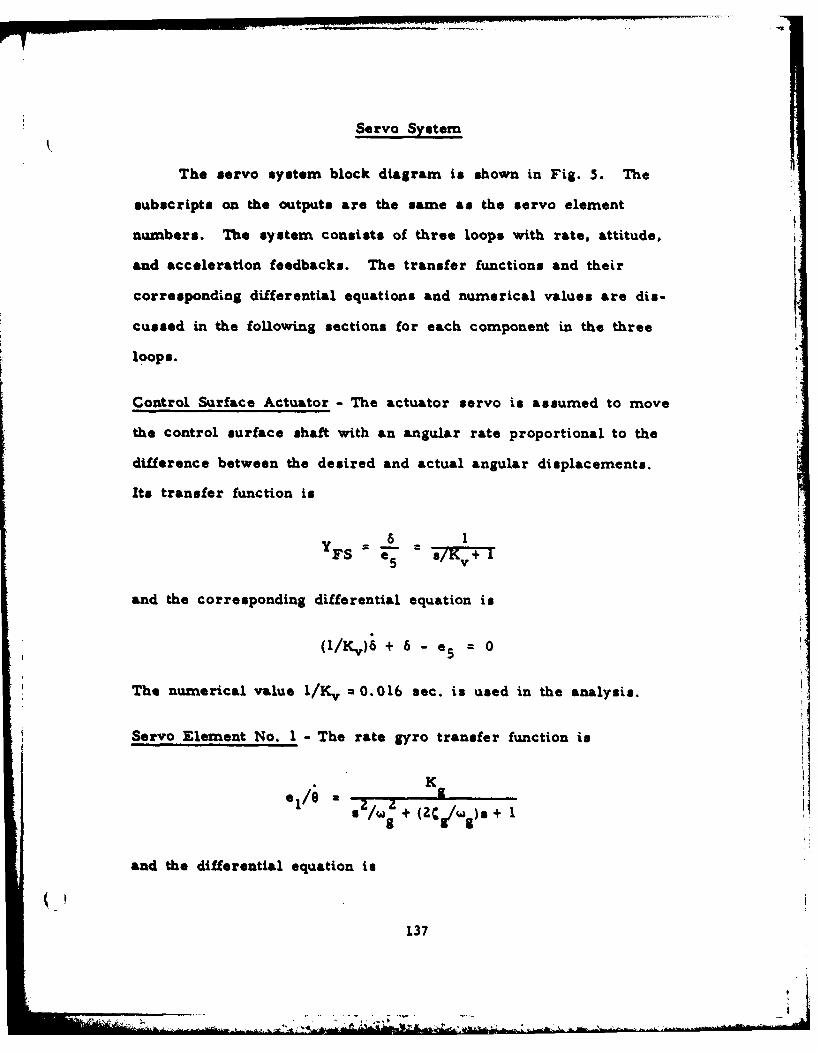
Servo System
The servo system block diagram is shown in Fig. 5. The
subscripts on the outputs are the same as the servo element
numbers. The system consists of three loops with rate, attitude,
and acceleration feedbacks. The transfer functions and their
corresponding differential equations and numerical values are dis-
cussed in the following sections for each component in the three
loops.
Control Surface Actuator - The actuator servo is assumed to move
the control surface shaft with an angular rate proportional to the
difference between the desired and actual angular displacements.
Its transfer function is6 1
YFS e 5 S/K+ I
and the corresponding differential equation is
(l/Kvi6 + 6 - e5 - 0
The numerical value l/K v :0.016 sec. is used in the analysis.
Servo Element No. I - The rate gyro transfer function is
I,?'/w Z+ (2 CW)
and the differential equation is
137
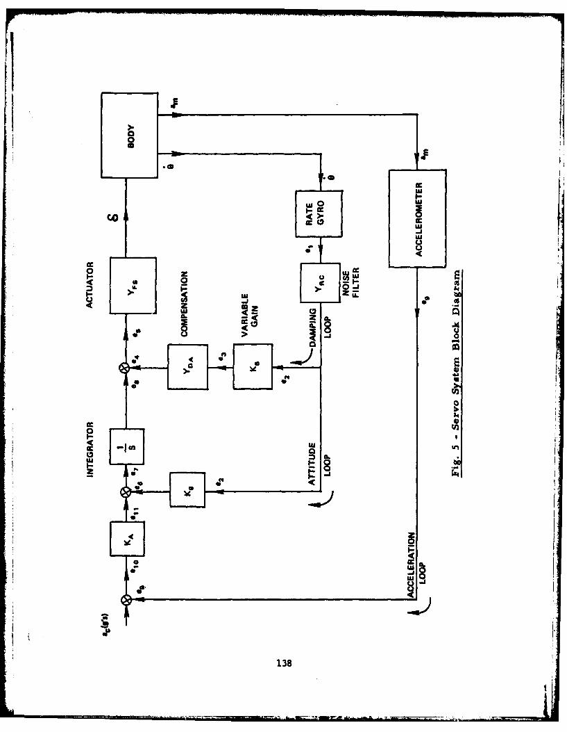
.0
CCC
- U10 UA
z U
2 'U
I- be8
al
zIrI Z p
ic8
a J"
cc0
OR4
ca.
ID.
a
138
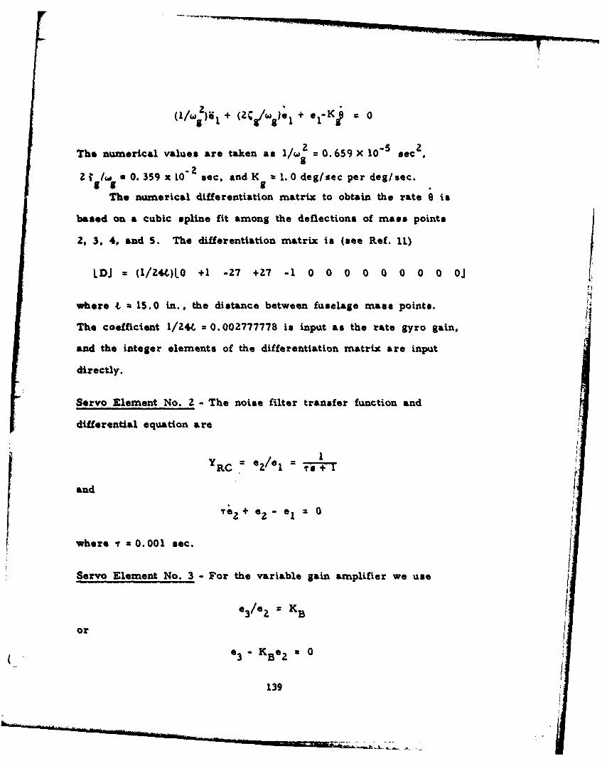
<'/'>',+ (ZC//wge, + elK< . 0
The numerical values are taken as l/w2 = 0.659 X 10"5 sec 2
21 f.i * 0. 359 x L0 2 sec, and K = 1. 0 deg/sec per deg/sec.g g gThe numerical differentiation matrix to obtain the rate e t
based on a cubic spline fit among the deflections of mass points
2, 3. 4, and S. The differentiation matrix is (see Ref. 11)
LDJ = (1/Z4L)L0 +1 -27 +27 -1 0 0 0 0 0 0 0 0 Oj
where 4 = 15.0 in., the distance between fuselage mass points.
The coefficient 1/Z44 = 0.002777778 is input as the rate gyro gain,
and the integer elements of the differentiation matrix are input
directly.
Servo Element No. 2 - The noise filter transfer function and
differential equation are
Y RC = ez/el rs+
andP
?+ e- 1 20
where r =0.001 sec.
Servo Element No. 3 - For the variable gain amplifier we use
e 3/eZ = K B
or
(3 - K Be e 0
139
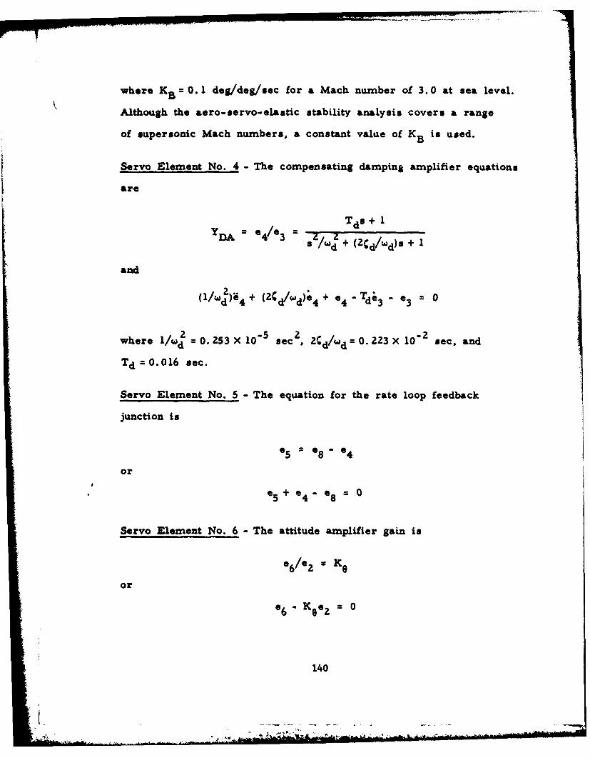
where K B =0. 1 deg/deg/sec for a Mach nuamber of 3. 0 at sea level.
Although the aero- servo- elastic stability analysis covers a range
of supersonic Macb numbers, a constant value of K B in used.
Servo Element No. 4 - The compensating damping amplifier equations
are
Y D = 4/3 ZW ZTds + 1
d + (2 C /wd)s a
and
dl/ 4 + Zd/wd); 4 + 4 - Td 3 - *3 0
2 5-2zwhere 1/wd =0. 253 X 10- sec , 2cd/wd =0. 223 X 10 sec, and
TdO= .O0l6 sec.
Servo Element No. 5 - The equation for the rate loop feedback
junction is
e 5 =ea8 -ea4
or
a+e a ea8 = 0
Servo Element No. 6 -The attitude amplifier gain is
0 /z= K 0
or
- K 9ea2 =0
140
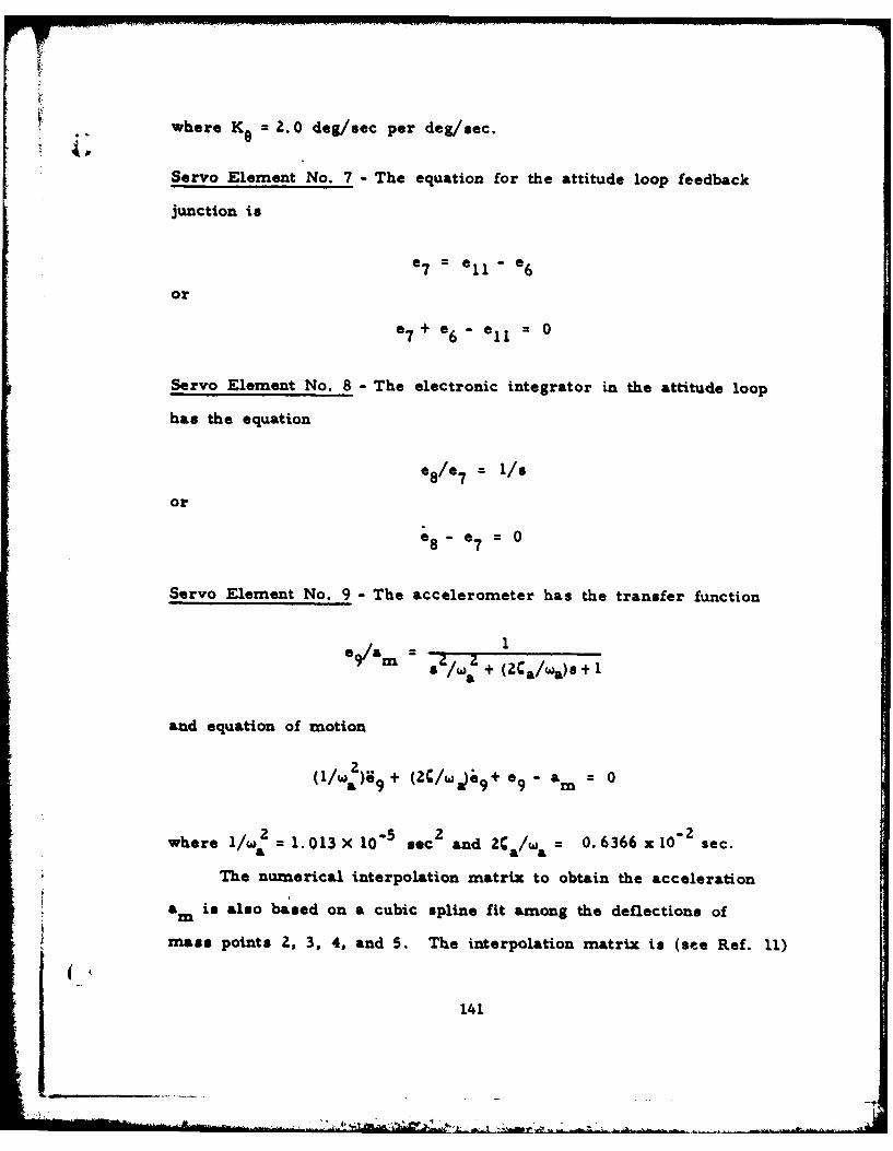
whereK 2. 0 dog/sac per deg/sec.
Servo Element No. 7 - The equation for the attitude loop feedback
junction is
a 7 = a1 1 -ea
or
a7+a6 11ll= 0
Servo Element No. 8 -The electronic integrator in the attitude loop
has the equation
a 1/8
or
08 -a7=
Servo Element No. 9 -The accelerometer has the transfer function
1M~ z s/w:z + (2Ca/wIa)s + 1
and equation of motion
21/a e9 + 2/Wi9 +09 a m
2 5 2 -2where l/wa = 1. 013 X 10~ sec and 2C a/w &= 0. 6366 xI10 sec.
The numerical interpolation matrix to obtain the acceleration
a is also based on a cubic splin. fit among the deflections ofm
mass points 2, 3, 4, and S. The interpolation matrix is (see Ref. 11)
141

LHJ (l/16)LO -1 +9 +9 -1 0 0 0 0 0 0 00 OJ
The coefficient 1/16 = 0.0625 is input as the accelerometer gain,
and the integer elements of the interpolation matrix are input
directly.
Servo Element No. 10 - The acceleration loop feedback equation is
el 0 = ac - e910 C 9
which reduces to
e + = 010 9
for the stability problem.
Servo Element No. 11 - The acceleration loop gain is
ell/e 1 0 : Ka
or
ell-Kaelo = 0
where K =4.0 deg/sec per g = 0. 002170 sec/ft.a
142
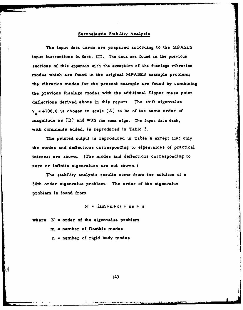
Servoelastic Stability Analysis I,
The input data cards are prepared according to the MPASES
input instructions in Sect. TII. The data are found in the previous
sections of this appendix with the exception of the fuselage vibration
modes which are found in the original MPASES example problem;
the vibration modes for the present example are found by combining
the previous fuselage modes with the additional flipper mass point
deflections derived above in this report. The shift eigenvalue
Y x +100. 0 is chosen to scale CA) to be of the same order of
magnitude as [B] and with the sam sign. The input data deck,
with comments added, is reproduced in Table 3.
The printed output is reproduced in Table 4 except that only
the modes and deflections corresponding to eigenvalues of practical
interest are shown. (The modes and deflections corresponding to
zero or infinite eigenvalues are not shown.)
The stability analysis results come from the solution of a
30th order eigenvalue problem. The order of the eigenvalue
problem i found from
N x Z(m+n+c) + ns + s
where N a order of the eigenvalue problem
m a number of flexible modes
n a number of rigid body modes
143

c a number of control surfaces
no a number of servo elements
a a number of second order servo elements.
In this example, m z 5, n x 2, c = 1, no = 11, and s a 3, so that
N a 30. The stability analysis results are printed for 22 modes
since 8 of the eigenvalues are complex conjugate pairs. Only
modes 4-7, and 16-22 are of practical interest. The seven
oscillatory and four non-oscillatory solutions are all seen to be
stable. The motions involved in the modes are summarized as
follows.
Mode No. Dominant Motion
4 Actuator
5 & 6 Accelerometer (critically damped)
7 Noise filter
16 Rate gyro
17 First body bending
18 Compensating damping amplifier
19 Flipper bending
20 Flipper torsion
21 Second body bending
22 Third body bending
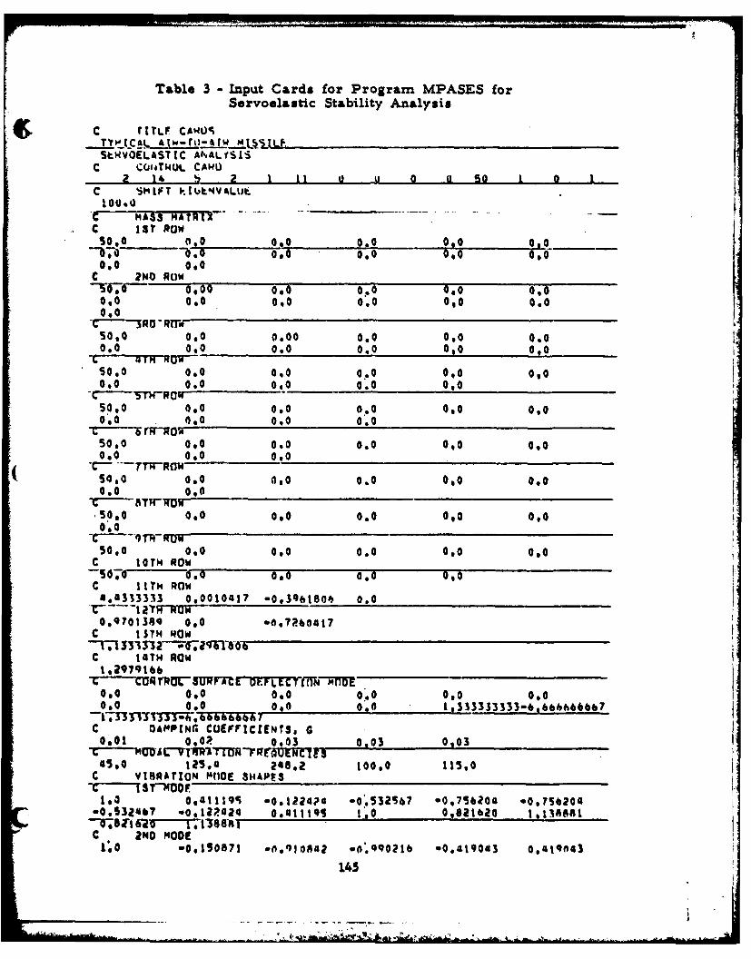
Table 3 - Inpuat Cards for Program MPASES forServoelastic Stability Analysis
c r1TLF CAROSTY'tQ~LC, &tw-rtj-4tw tAUSLp,StWVOELASTIC AN~ALfSLSC C01tTWOL CA4L
2 14 b 2 1 11 ai 0 a so I 1C SMLFT I1'AkANVALUt.
.c MASS MAYR12C 1S? Raw
0I0 0I.00 '
C T6 ? NO RUN00 00Wi I ICIO0 CIO 00001 0,0 CIO
000
Sol 0,.0 0 0 0.0 CI 0.00.0 CI0 0.0 0.0 0,0 0.006 qrM RQW
Solo 0,0 0.0 0 .0 0I0 0.00.0 0.0 0.0 0.0 0I0CT" Ku"
50.0 0,0 0.0 0.0 0.0 0.00.0 4,0 0.0 0'.0
50.0 0.0 0.0 0.0 0"0 000
10.0 0.0 0.00,
50.0 0.0 060 0.0 0I0 CI0
s0l0 0.0 0.0 0.0 0I0 0.0
C loT'. ROWs.600.0 0.0 0,0
C I IT14 ROW4*4333333 0.0010417 -09396 180 6 0.0
c IS'TMROW
C 14TH ROW1 ,29791&6___________________
0.0 0I0 0.0 0.0 0.0 0.000.0 0.0 0.0 0.0 1,333333333-6,666666b7
c OAMP[NC COEFFICIENTS, G0.01 0.0P 0.03 0.03 00
45.0 125.0 24a8.z 100.0 11560c 1 StRTO "OD 31APE
1.0 o9atti~r) *o.122oa -0.532567 *01756204 *00.?520G*0.53Z4b? w0.12R424 COMMit 1.0 0962tbao 16138681T8v a216 6T -- 71186-81C 2ND HOOE1'.0 .00150871 -6*910nA4 0.o.Q90216 .0,419043 0,419f643
145
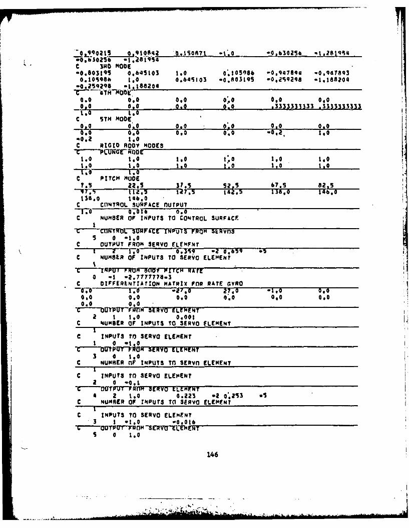
O.qqo2s 0,10842 091So871 -1.0 .0t630256 -l2tS4qd.0.630256 .i.2lSc IRO MODE"0,803195 0,645103 1.0 0'10508b -0,qal1qa -0,9478q30,105Q6A 1.0 0,645103 -0.803195 *029298 -1.188204*0,25q298 -1.18a204
coo 0,0 0oo 0.0 0,0 0,0_O0 00 O9 00 . ' ,0 3333333333 .3333333333t,0. tO
€ STH ODE.olo °' o8o o; 00o000 0,0 0 0 0, 00 00,2. too0012 IO
C RIGID ROOY MODES
1o 10 1.0 1.0 1.0 1.01,0 ISO too 1.0 Ito to
C PITCH NUDE7.5 22.5 37,5 says 67.S 8225"-1T 144,3 1-?;.5 142,5 138,0 146.o
136.0 1460C CONTROL SURFACE nUTPUT
-I'SO 0- 16 00C NUMBER OF INPUTS TO CONTROL SURFACE
I
5 0 -1.0C OUTPUT FROM SERVO ELEMFNT
1 2 1.0 3So q -a 0.659 5C NUMBER OF INPUTS TO SERVO ELEMENT
t'CT PUTROCTrIr'TCH RTrE
0 at -2.7777778.3C DIFFERENTIATION MATRIX FOR RATE GYRO-0.0 logo 27,0 *1,o o0.0 0,0 090 0.0 00 0.00.0 0.0
C--' UTVT"fTig SERVO ELFMENT2 1 ISO 0.001
C %UMBER OF INPUTS TO SERVO ELEMENT
C INPUTS TO SERVO ELEMENTI 0 "1.0
Cb P U~I~U~1SERVO ELEMENT3 0 to
C NUMNER OF INPUTS Tn SERVO ELE NTi
C INPUTS TO SERVO ELEMENTa 0 00,1 __ _ _ _ _ _ _ _ _ _ _ _ _ _ _ _ _ _ _ _ _ _ _ _ _
_C JTUTT ffnW1[9Vp ELMFNT4 2 to 0,223 -2 0253 a5
C NUNRER OF INPUTS TO SERVO ELEMENT
C INPUTS TO SERVO ELEMENT3 1 *1.0 *0,016
C- OOTPOT-RIM-SEWRu1-L-E-ENTS 0 1.0
146
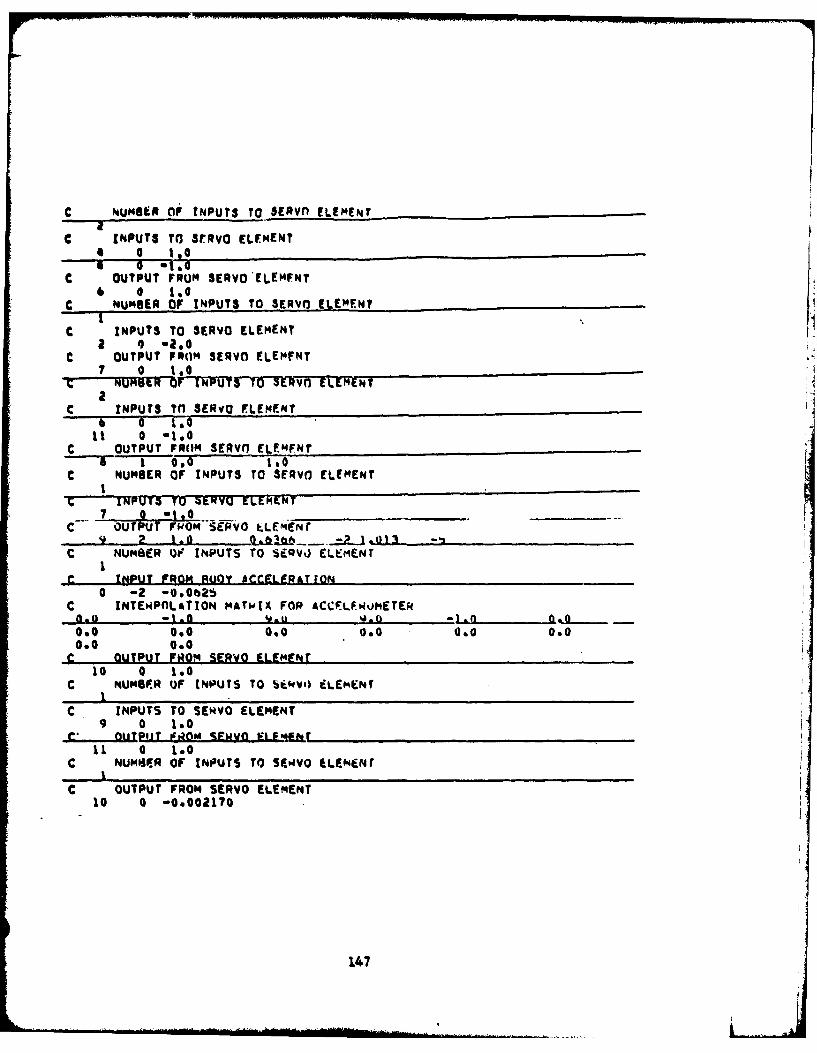
C NUMBER OF tNPUTS TO SERvn ELEMENT
C INPUTS TO S3RVO ELEMENT* 0 1.0
C OUTPUT FRUM SERVO'ELEmFNT6 0 1,0
C NUMBER OF INPUTS TO SERVO ELEMENT
c INPUTS TO SERVO ELEMENTa *a- ,
C OUTPUT FRO(M SERVO ELEMFNT7 0 1.0
T NUNSI r OINPU TSIO ELEME~TWENTa
C INPUTS TO SERvO ELEMENTb 0 100
11 0 .1.0
C OUTPUT FROM SERVO ELEMENT- 1 0.0 10
C NUMBER OF INPUTS TO SE3fRvO ELEMENTI
INPUT* T'O MERV0 ELEMENT
OUTPUT FROM SERVO tLEENr9 2 1.0 ~0 ~ -
C NUMSER OF INPUTS TO SEQV) ELEMENt
INPUT FROM RUOY ACCELERATION0 -2 -0.0625
C INTEWPnLaTION MATwIX FOP ACCFLF4uMETE0.o -t.0 9.u 0.0 I.f O a
0.0 0.0 0.0 0.0 0.0 0.00.0 0.0
c OUTPUT FROM SERVO ELEMENT10 0 10
C mUMBPR OF INPUTS TO Skkv) ELEMNr
C INPUTS TO SERVO ELEMENT9 0 1.0
el otjPliJ FOm %EMVO FLF";hr11 0 1.0
C NUMPJER OF INPUTS TO SEkVO iLENemr
C OUTPUT FROM SERVO ELEMENT10 0 -0.002170
147

I I
, . .o* 0 0 0 0
U * IiS,# O
*,. ,= 0o 0o 0 0
!... . . z. ; .
.+* *..
ww 00 n
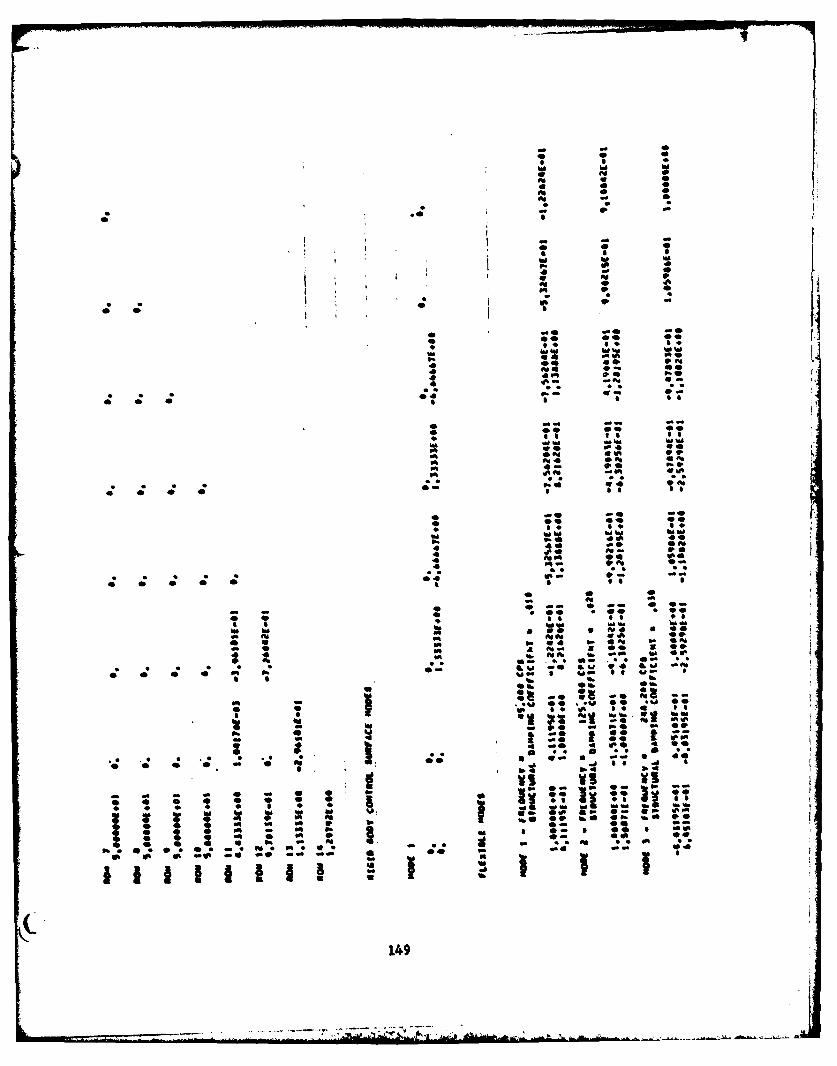
- ~ . Wk
VA wIV0% a
* 4WI 0
WI 0
16
1
WI a
** S . 416,0 op 0. 06 1 00
WI ~ ~ l 4 9
Ce 0 0
4 .10 9
mi 0 4;4
149 W
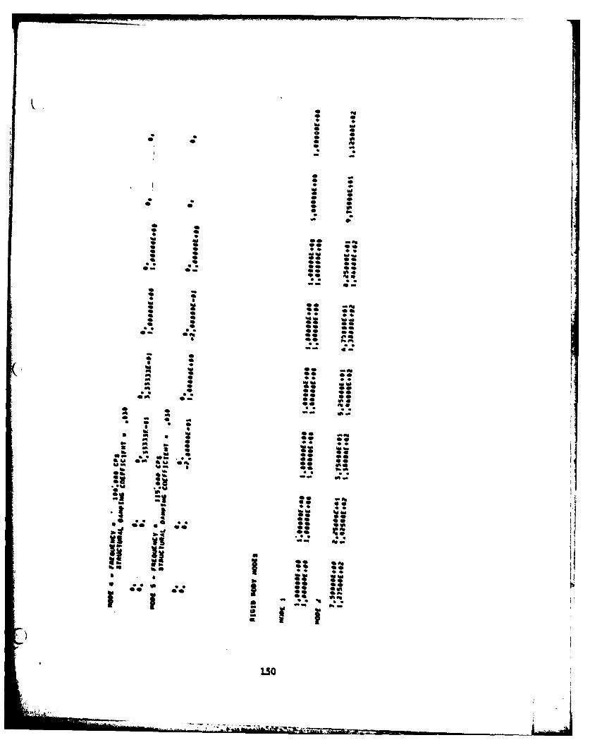
0Al* 4
* 0 0
** Al- -
* S
* a* 0
00* 0SI
*4 4.* p.
0* 04 4
be bi 00 **
* 44
* ~ 00S. ** ** 00Oa 0000 i~*
0 - - 0 a
be be ** Ai
* 0 44 *400bebe beO00 00
* 005* 00 00* 00
- - C -- 0* 0* 4
lb -AlAl 0 44 44
a * ~. ~,00 00
0Oa 00 **
so bId** AlSAl -a** - 0 -* 0 *
lb* Al * * 00 **
Alp. 0 p. *lb ~ lb * .0 babe
SS 50 ** ** @0&U 00 ~l.l 0Al 00~. * ** 41q
lb *. p.o.9% a a ~ -
0Al
lb 00
*. * *, 00 0000
00 S.
- a - -
ii ii I ;~vS * *0
I if ~If 00a *~ ~:~ I
£ j)
3.50
~i.
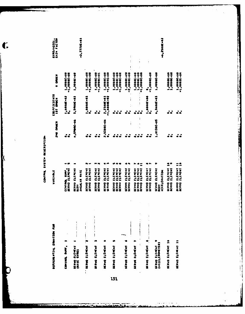
ftC; .ftSft
-. p.ft I
ft4 ft0W S
** 0 00 * @0 *@0 00 000 0 0 00 *0S 00 0 00 00 00 @00 30 000 0 0 *@ *@K.. * .. 40 *4 9*4 ** 4*9 * 9 9* 40
ftft ~ ftft ftft ft.~ ~ ftoa ft ft ftft 34a 00 0 @0 @0 @0 000 00 000 0 0 00 0000 0 @0 @0 00 000 00 000 0 0 00 00@0* 00*@ @00 *@ *@ * * 00 Oft0 00 0 00 00 00 000 @0 000 0 0 00 @0
.. . .. .. *. *.. *. *.* *. * .. ..- - - - - -- -- --- - ft -- - Oa - - - - -
S S S S S S ~S S S
aft ft ft ft aft *33 0 0 0 00 0 0
* 0 5 *5 9 9 SU K
ft 3 ftf 0ft4 0 ft
B! ** * ** *~ ** *** ** *** ** *U S
*0 0 ft* 0* S
ft fta I * 0* ftft -ft WI 0I
4. . *. 4* ** ... .. .. * .. . .. ..& ft 00 4 @0 00 ftO 000 00 000 00 - 00 00ftS.
Kaftft* -. - ft ft ma ftO* 4V4 ft4 *ft 0 00 -.* - - -0
eft ft ftft ftft ftft ftftft ftft ftftft *ft ft ft ft ftftft .88412 3233 383 33 312 3* 3J33 a.
* 0 aua.aziz.ua:s:zauaaa La:ft 4 Oft ft U ftft ftft 34 44.4 ftft .443 44 ft ft 44 ftftS ..a-h a~ ~a .i..a..a 4 -l.a
.1.4 ft U Wft ftftU 4 0 4 ft
ft 00 3 ~1 00 @8 00 j@i ~2 000 00 0 -. 00 00ftft ft bb bft ftft ftft **W ftft Oft30 3 23 38 083 00 303 80 LOU SM Sb~2 2K 23 22K 22 ~ 33 ftft
0 @3
Ift4
ft - ft 0 ft 3 p. 0* 0 0 -0
~ ft ft ft ft ft ft ftft ft ft
- 3 3 3 8 i 3 3 8ft a a
- - V V V V- -- - ft ft ft ftft . ~ - ft ft.1 ft .d .d .d .d .1 ft
V ft 0 0 '~ft N Oft 9 9 9 0 9 9 9 0 03 ft Oft 0 0 0 ft o 0 0 ft3 3 34 0 0 U 0 0 0 0 0%I 00 U ~ K I* ~ Ow 0 U 2 2 2 U 3 K
151.
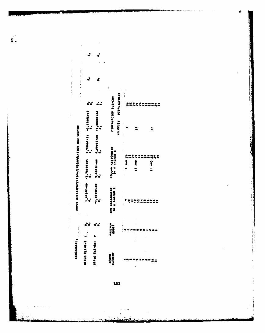
* .* 0
** *~
S.a
a ** .* Id
S. S * Id .1 - a
Id b~ - 0
* 0U & * IvI mba
* 0* U* 0 S.IS. 0 3- *~ *S 00
~* 0**
0 ** * 0 *a I IId Eq q 45- Id
a * 0 flq .~ * -- 0 0 - -
~ '5-5- me 9@ b.DS. *q5*5- 0 0a * *5- . . 96: : ~ a~. 0 0 1!5- 0 05- 0 0* * S S * ~j [email protected]. -* U. - a ---- ----
U
5- 5!.. 9* S
*o **'imb~5-000aAIO@
aa. *
.1 S. aa. .g
S.
5- 0 0* U: ~S*U545-090..
32 no
U
152
*5 . S
* A W% 0 q5 0 0 01
400 hJj 0z 0g * 14 o O
k400 00 0 q aloo Too "00 -0 00 j 65 ~
a OP 4 Eq. P. e
4000 4000 A00 4; PO P0 4005 00;40 0,; 000 at0 00..4; 4.;4;
00 00 0II . I, C
P. 5E P.R
fit 0 0 0
-00~ ~~~~~~ 00 P5 a9 00 00 0 0 0 00 090 5
00oo 4 e -00 00 0 0 0
as P4P
0-00 # 4000 001000 4000 0000 0000 04004 00004 050 00004;jj;
se 000 S t e 04 0 %000 0% S:00 4w 01 64
I.'A
40 P.00 4OO 400 TO 00
o EqS Al 0 4 4 0 3
S0
0I I S
S
I SSSS
@00 500 *OS 000 000 050 000 000 000 005 000 00 000
- 0* 0*w V0* 0* 05* * 0* 0* 0* S
*** .*. **. .. * .* . *... . *9 *** **. ... *** **. . ..000 005 500 000 *00 000 000 000 000 000 *0 000 000
* Ig,* 0* S
~ ~ I 04 0000 0000 SOOS 0000 0000
*0*00
0000 0000 0005 0000 0000 0000 0050 0000 *~00 0000 @000 @000 @000
* 0* * I
* * IS
* 0
0000 0~00 0000
-* * I *00*ii I i I
'~0 I * II I I i I
00*.** . .. ** .. ** 0@O~ **** 4 0@00 0000
0500 0000S t I I
IIEII * I*4 I I
I I I
.1 0000
0000 **o* so.. .0.0 0.00 0000 0000 0000 0000 0000
* 0
* I U,I I 0
I * If'5** ** **** .505 **** 5555 **SO *555
@000 ')000 0000 5000 0000 0000 0000 00-0
(-S
154
-~ ~ - - ----- ** "4.
I. - 9 J~ jj~: 4* *** . A. ....~. 0@@
Ip.0
eeS @00 e *.@ *04 000 000 OAS 000 *e0 000
* II* [000
9~0 4.t.. ... * ... * .... ... S ***~ **** **** **** *... **** * ***
@000 0.00 0000 0000 *0~O 0000 0000 eAje. 0000 0000 0000 @000
01 4
3 00 40 Au0 00 4
.5** ***S *SS. *.SS *555 00000 0~00 0000 @000 0000 0000 0000
0000 .. aO 0000 00-0 0000 5@S. **** . S.. **S* **S* ***S *@SS
* 4 I
* 00 0S -~
0 0 9
I * Au 90 0* 4
*5*S *S.* ** *5 0.55 *SSS -0000 0000 000 0000 0000 5 555 i... **** *#** *555 **55 5555
0400 0000 0000 @000 0000 000. ****
0
0
0
0*5*55 . a **** 5*50 ***5 *5*5 *5*5 ** S * *5550000 0000 0000 0000 0000 0000 0000
00 I
* I 3 I II I I* I
4 J~J jAi; ~ ,~** ,*,,* I95*5 555* 555* 5555
I I * 0000 0000 0000 0000
I-9 I UI. I
9 I~.**. .... *... *.... *.~. 2
00~0 000.0 0000 0000 000.0 *s.. . *** **** *..s *... ....0 0000 0000 0000 *900 0000 0000 @000
155
',,.. ~0
~ZZ272
* 0~* 0 0I . 9* w w
0* 0* 0*** 0
999 .999 *** 0 0 999 999 999 999 999 999000 000 000 99. .99. 9.. .9 9 000 @00 000 000 000 000**~ **~ 000 000
* - 0
.. S 9 . .* 5
. . .
*.* 0 0 0 I* 0 0*0~ 0 0
* 0 0 *~* *~* 999 999 . 999.99 999 .9. .9. .9. 9.. .9. 000 @00 @00 000 000 060000 000 *0 *0 000 @00 *0i~* a
* * 0 0 0* 0 0 0* 9 9 9
* 0 0' 00* 0 0 0* 0 0 0* 0 0 0* 0 0 09999 9999 9999
9999 * **** **~* .*.* ***s *~. 000- 0000 00-0 @0-0 *00~ 00000000 0000 0000 @000 0000 0000 0.00
o* 0* 0 . 0 0* . . 9 Iw . ~Aa0 0 0* Al* 0 * 0* 0 0 0* 0 0 0* 0 0 09999 9... 9999 .9999 9999 9999
9999 999 9999 9999 999 9 9 999 99 99 **** **o* 0000 000- *00~ 00000000 0000 0000 0000 *0~0 00-0 0000 9 S
* 0 0 0 ** 0 0 0* 0 hI hihi hI 0 00 0.* 0 0 0* 0 0 0* 0 0 0* 0 0 0* .* 0 0* 0 0 09999 9999 9999 9999 9999 9999 9999 9999 9... *9990000 00-0 00-0 0000 0000 0000 0000 ***~ 000- 0000 0000 0000 0000S I
* * * 0 I* 0* I hi
0 a
9999 9999 9999 9999 000- 0000 0000
00-0 0000 0000 0000 0000 000-
I II. I. I~o I I I'I0 0 **** 9999 9999 9 9999 99999... .9... .9.. 9999 9999 9999 *** 0000 0000 000000w 0000 0000 ~ 0000
* It * I * II.I I
I Ii II ,' 0I- II; 0* 9... 9999 9999 999 *9*.9999,.999 .9.9 .9.9 9... .9.. 9... 0000 0000 0000 000~0 0000 -0000000 **oo 0000 0000 0000 000 0000
. I * I I
156
* - - -- ~~-----~r --- ~--,.~- - ~1** *-...' -
* £,.*~. *.~
S69
0S000S
9.. 9.9 9.. '*99 9** .99 9** * * * 9.. .9.,
SSS 000 000 000 000 000 -00 *** 000 000
0I 0
I t I V* I 0
I 0I 0
* 000
*9~* *99 999 999 9** 999 9.. .9. 9.. 99*
000 000 000 000 000 -00 000 *00 @00 000
* I* I 0
* 09.
* VI I
000
9999 9.99 9999 9999 99.9 9999 999. 9... 9... 9...
0000 0000 0000 0000 000 0000 0060 SOS.
009
* V00
, 0000
9999 9999 9999 9999 9... *9 99 9999 99.9 9999 9999
0000 0000 0000 -000 0000 0000 0000 0000 0000 0000
0
(. I 0'I V*
0* 0
000
9.99 *.*~ **** **** ***q **** **** 9999 9999 9999
0000 0000 -000 0000 0000 0000 0000 000. *000 0000
* , , I [9 I I i 0 I.K 0
I * 0
* 3 I I I 0* 0I.... - 0- 19999 9999 99999999 9999 9999 9999 999. *999
000 0000 0000 0000 0000 0000 0
I: * I IIi~II I I II 0.,'
jfiIi~ 310~00 0000
I I 0
I I II 0 I
I *I * I I 00
I.... ***~ **** *~~* **~* **.* ,*** 9999 99199 9990
0000 0000 6000 0000 0000 0000 See. 000 0000 0000
I I S
157
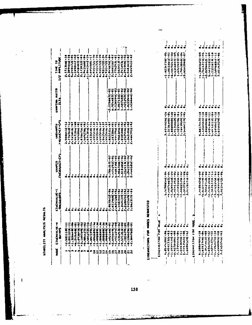
o ,._*.p... ' i JI I I I I I I IT U. ,." %u C-: v
" l l l i ' ' ea' I ,.. .....a. . .e . . . . . . .
., I SA I-1w 14 Mie.000 0
9f ;,I -ON94. Id Id 1 *0 Id Tf. A .3
000ll l ''Or il n a "' -°"M ov 3a. a 491A9 N". 2a a es..
* . . . . . . . . p .. .. .. . , i i. ., .
Id , 0.00. i
p 'l l .-- a.e , I I- I
4p 414% 6
4P
INA itI 2 II *-PEGI~ I.00NE96 I -9
, , 0 4P * P V -4 VOA 1-~~*,' zoo-'a 44
eeeemee 4 # 6Ift ]_N 11 1
I I il l !~~IiO .9..pPO p iltpS 9*. ..* *--O91*9J
I------ I.' I
•~ 08
Q11
-~~ ~~ o.- - ~ .
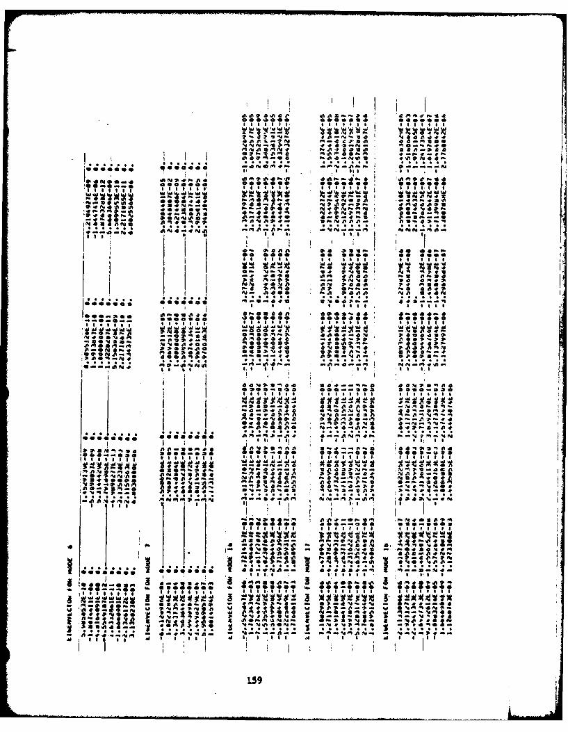
7I 06 T I l t I
A 00 A0I00030p4 A a 0
f"A~ I. 'r. m '
M-CPf p P. P.
.dft a ** *% ; * % , * * *: * 1 -.
ANO WN1 N - -t
* 0 0 0 0 0 0 0 0 , 0 0 0 0 0 0 0 0 0 a 0 0 .
-:N 20*~~N *AM .4P--e fftS
I I IO-on a09 *AA4 *
A0 0 0 T0 * 3 I0F90 00 8 0
4~~0fteft IOfl. a 0 0-*0-141,411
*~A IV *C****.C** * ,A*
-dft~~fl -1.00* . 4E f,04.~IS *S ~~~iS 1 S .
Is IIIJ0 ~ . A EW0 0 le 9~#faA40 4EP4I
sIs 0 0 I mm&P ,-
4co.a 0088 000'a0Up0 s .00 St
maVat S ~ ae4M 244! 4-l
Aft0~~a~j~U4 i*, Nc0
-AA. 'V N. NO01 1 m0
I f ot -2 0 -- 0 1 100
tie,#,Y Dme a *aaase
ieao06a. 4401i # *.0 e~ U
CC,... ~ 1 19 C .. * ** * *AC . C 3 *C . .
I Is
Ut ~~ ~ ~ t :1 -0 Al aAso
H"M uIs aa
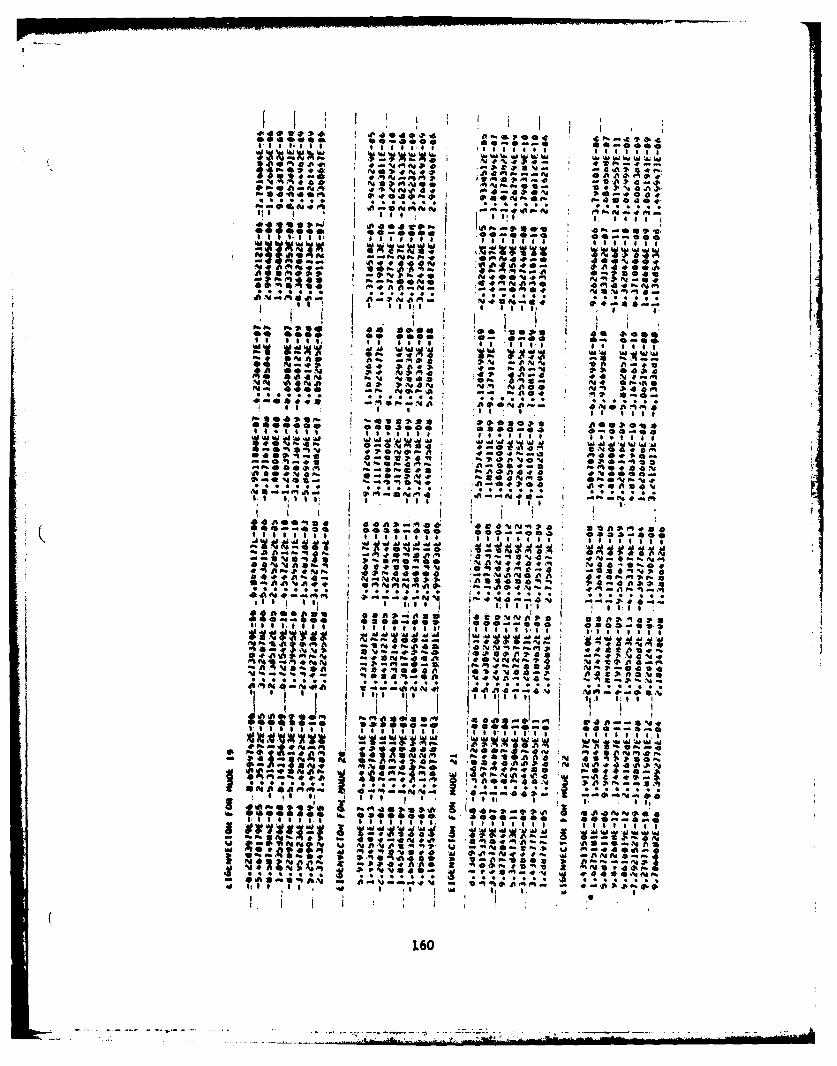
il
ftiS. . . . . . .4 . j Ed I
I .1 I I
es es e e , e ,* e e e . s s e i
4 3-0A 0-. 0040+O
SI :S I65 'I I I I I l l l l
WVXX I I I I 0 1ft A" f W910 'lo 19 t W %W i .1O
I t t:
00 ~ ~ ~ A N00 ft. P.,* I -0 -. 0
~ee ose, *ee iee a, Se
;4;4,A.0 n 0 ;
i-21
No %- . T+ -
S 1 & I I I ?I'-- -a 0* 11 a 04 -1
I e O O o s e Ietsn . o. I 0 2 .4 ,l4
A a 14 .0 ;I A ; ,II I . . . I t
I;I I I I I I *ell t l l l l I I I I I I I I O *emhgg
.. a S # S 4 A
." z ... . . . a 4 Z ! A..-
4p *49
'semeege~~~ Gi el m a e-e S ee g-h S0,0,0
10 40,1 TI. a ais
*A 24 4. 4-4fM
f :;; 0 4 & 44. U j
UI I I - OTTO *** * . U T TT T IU ** U U * *U **
ft P% v s vi S' e
HfI 't' v ; "
do II a 4P
U 1.5 ~ A , 0 t..........., -.
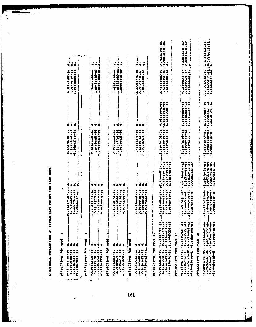
s " I g I h
' ' ,~ , I a. I
so see ,
4O 0 m I 0 . O '",aOr0 Al v .1.0 0.00
: , Ai P 0 ,N* a. i am.. aI
o o!
.0 ISA-1@ , . ° . *.., 4P. EAI.
*II iiIO ' A.O0 I OI I I i.ii t 9I *fI I Il l I
00 a0 *as *q, 9 *
O* I I I
41,0 a '( J,°°- " 'I I I il I
NO , aaA"% I
I - ; Q, 0, 1 at
Ilosa a m a m0; 9a m ao
S A S%14 0"A,
-M -4 3-4P
9W to *11"
-I $eq Eq. lo lo o
400,0i 1,, 0000 4, SO' ee
4-.. 1; " S
q~qa :~o ~%*'M- 4V V.
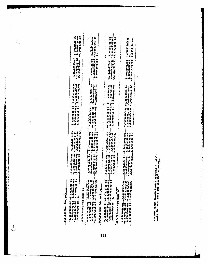
%*I 1I, 21.4
aa] I I ie
=,,- s
wS... ..
I1 I 5-,I
WNW 's '
4 ~ m f 41
*I -- , ..,
2ie~ : ICO a.. t ---000 @
' '•
Oa II I'
, o -e
" : :: . t ",
f t 't I 2J1 L
OtIII 0
04
2d*% fi. I
'w, I O
I SO
~~162
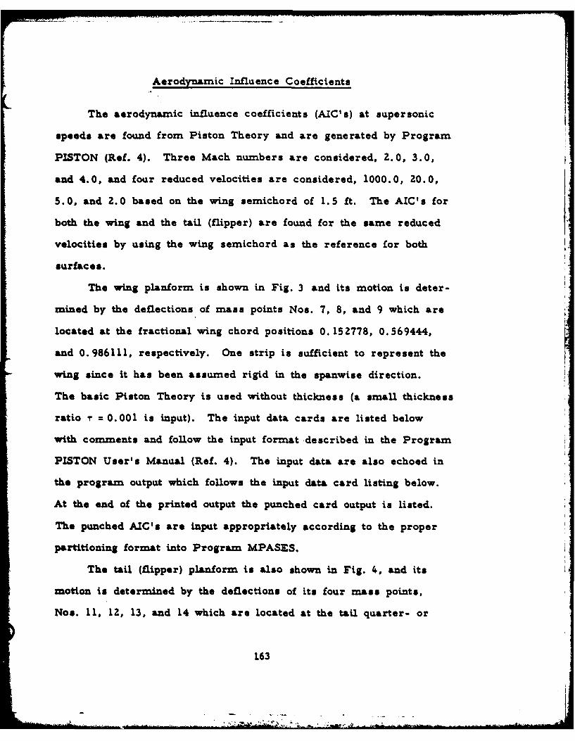
Aerodynamic Influence Coefficients
The aerodynamic influence coefficients (AIC's) at supersonic
speeds are found from Piston Theory and are generated by Program
PISTON (Ref. 4). Three Mach numbers are considered, 2.0, 3.0,
and 4.0, and four reduced velocities are considered, 1000.0, 20.0,
5.0, and 2.0 based on the wing semichord of 1.5 ft. The AIC's for
both the wing and the tail (flipper) are found for the same reduced
velocities by using the wing semichord as the reference for both
surfaces.
The wing planform is shown in Fig. 3 and its motion is deter-
mined by the deflections of mass points Nos. 7, 8, and 9 which are
located at the fractional wing chord positions 0. 152778, 0.569444,
and 0.986111, respectively. One strip is sufficient to represent the
wing since it has been assumed rigid in the spanwise direction.
The basic Piston Theory is used without thickness (a small thickness
ratio T = 0.001 is input). The input data cards are listed below
with comments and follow the input format described in the Program
PISTON User's Manual (Ref. 4). The input data are also echoed in
the program output which follows the input data card listing below.
At the end of the printed output the punched card output is listed.
The punched AIC's are input appropriately according to the proper
partitioning format into Program MPASES.
The tail (flipper) planform is also shown in Fig. 4, and its
motion is determined by the deflections of its four mass points,
Nos. 11, 12, 13, and 14 which are located at the tail quarter- or
163
three-quarter chord positions. The tail has been assumed rigid in
both spanwise and chordwise directions but to bond and twist about
the actuator at the root. Two equal width strips are used to account
for the bending motion. Except for the chordwise and spanwise
locations of the aerodynamic control points, the tail is treated the
same as the wing in terms of input to Program PISTON. The input
data cards are listed below those for the wing in the following pages
and the printed output of AIC's for the tail follows that for the wing.
Again, at the end of the printed output the punched AIC's are listed.
164
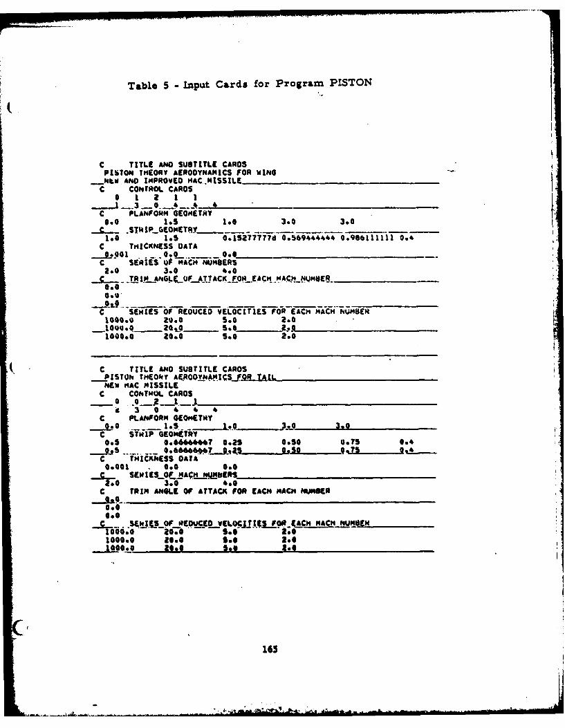
Table 5 -Input Cards for Program PISTON
C TITLE ANO SUSTITLE CARDSPISTON TIHORY AEROOYNANICS FOR WING
_Nt. ANO IMPROVED MAC..MISSILEC CONTROL CARDS
0 1 1 1C PL.ANFORM 6IEOMETRY0.0 1.5 1.0 3.0 3.0C STA IGEOMETRY
1.O 1.S O.15377778 0.569444444 0.986111111 0.4C THICKNESS DATA
J,0010 0. 0C SEriESu MACH NUMBERSt.0 3.0 4.0
_._..TR IMN_ANOLLO ,_O.A.TACK FO E*a_(CN_MACN¢._ NUJMaE A_______
0.00.,h*
C SEWIES OF REOUCE VELOCITIES FOR EACH MACN NUMBER104O.0.20.0 __ .0 2.0
1000.0 .00 S.o 2.0
V C TITLE AND SUBTITLE CARDS-- PISTON TNEONY AEROO"NAM;S.F.R TAIL
NEW MAC MISSILEC CONTROL CARDS
k 3 0 4 4 4C PLANFORM GEOMETMY
0 o .. .... I _S.. ___ . _ so 3.0C STMIP GEOMETRY0.5 0.666666467 O.2S 00.75 004
-- _9.95 S...... O 66666 _9t . O S S 0*4
C TNICKNESS DATA0401 0.0 000
sC , IuS_OF_.A,_N ERS2.0 3o0 40C TRIM ANGLE OF ATTACK FOP EACN MACH NUMBER
OoO
0.0 --. 0- s StO1000.0 2160 see 206. .G2006 See Joe
165
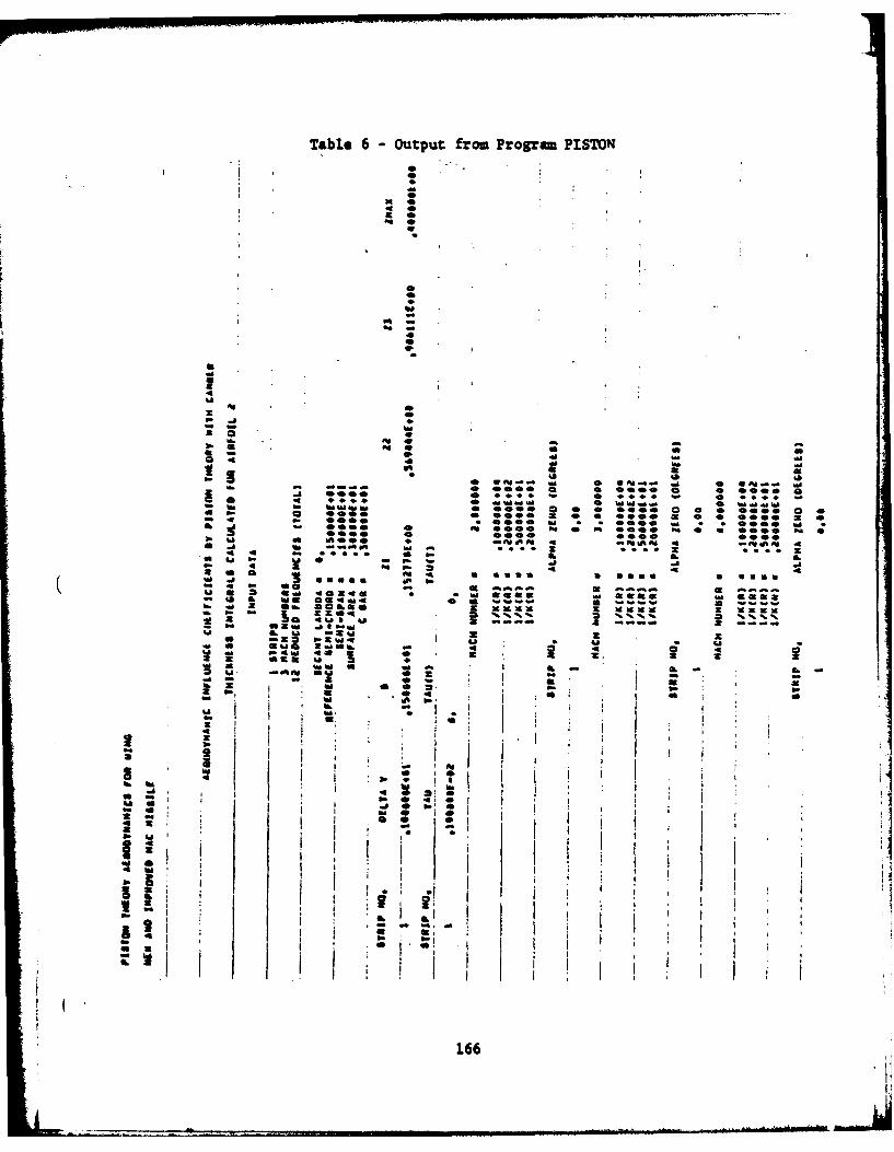
Table 6 - Output from Program PISTON
M z :'%
Z. 0l :006 a 0 ZDO
4D*
40. 0000O~ g
no :. 41 .9¢ 0a .-
wxw
° 1 Z
W z
a. o
44
U1. .
I '?~
. . .SM :
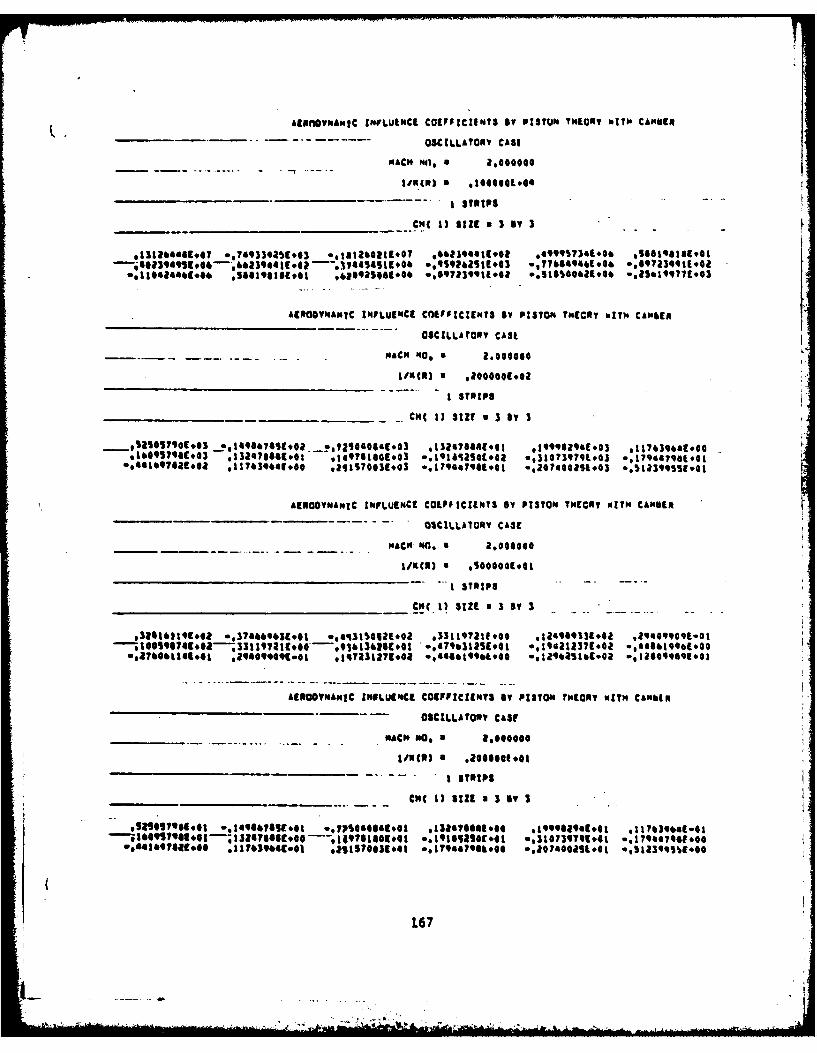
Alp"gnMawIc NVLutmCE COEFFICIENTS By PISTON THEORY withe CAMSER
- - OSCILLATORY CASE
14ACH fi, a 2,000000
JimC1 (N a 10000L*44
1M1i SIZE a I BY 3I
£EROYEADStc INFLUEN4CE CnIFFICIENTS BY PISTON THEORY with. CAlobaf
OSCILLATORY CASE
I STRIPS
__________________CM( 1) SIZE a 3 By 3
_*sIlqoco$E,3 ?1109807419*02 __28125040604E~3 *132147~ 4941 0999SlJeE603 $:1Th3,.aE001*lIOS790C.03 a 1324u8e6104 ,149781809.03 *,a91salsotoda 0,3107199t.03 **l?9ooqa~.oot.
*,4~000~*,~*l1&3001 *211~S70031#6S *.1"70 E.101 *00402I4043 *.sl3Wfs~E.0
AERODYNAMIC INFLUENCE COEFFICIENTS BY PISTON THEORY WITH CAMDEN
-______ -. OSCILLAIORy CASE
_____________MAC" HO,. a 2,006000
Ii()a STRIPS
____________________________CM( 1) WIE a3By 3
AIEEOYAHIC INFLUENCE COEFFICIENTS IT P13TON THEORY WITH CAMbtR
OSCILLATORY CAUt
________MACNM, o a,040680
-~ ISTRIP$
____________________________CHC 1) SIZE a 3 IT I
*IS091?q6S.0-;IZ0Tglgcoe----.-9149761841#41 0.0118S4041 6,310739T91[o0i *,l700aT9eE.@0
167
1jai
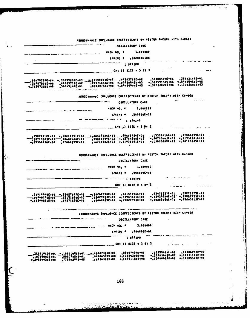
ACRNO@HMIC INFLUEN4CE CO9FPICZIE%?3 SV PISTONS ?"COOT MIT" CA*§tft
____________________ - - - OSCILLATORY CASE
- ___________ MACH '40, $ ,*Go000
I STRIPS
________________________ Cht 1) Sin *3Sby3 -
hf300YmAwIC INF9LUENCE COEFFICIENTS my PISTON Thica? WIT14 CA*GUN
__________________________________ -OSCILLATOOT CASE
MACH '40, * 3,0440000
_____________ ____ ___ ___ __- - - I STRP$
ACROOYNAMiIC INFLUENCE CaIFftCtENT3 81 P13TON ThIG'? MITH CA"VtO
_______________________ * - OSCILLATORY CASE
-~ --- ---. .. ACH No, a 3,000000
_____________________ -- I STRIPS-.
£ENOOvNAmfC INPLUINCI COEFFICIENTS BY PISTON THEORY WITH CA"690
OSCILLATOY CASC
____________.MACY* No, 3,090000
I STRIPS
____________________ CM( 13 SIZaISSY,3 .~
,315lltatI1oo *0,11tlc4l 044yS41732 tEol. *SSO60184@l 1)33SS146001 4TT06OQ99tool
*:1071500310G Sesa.I *.e.0I@ .,£TS3bSIoo 2,07036631*41 .119111811*00
168
-7-
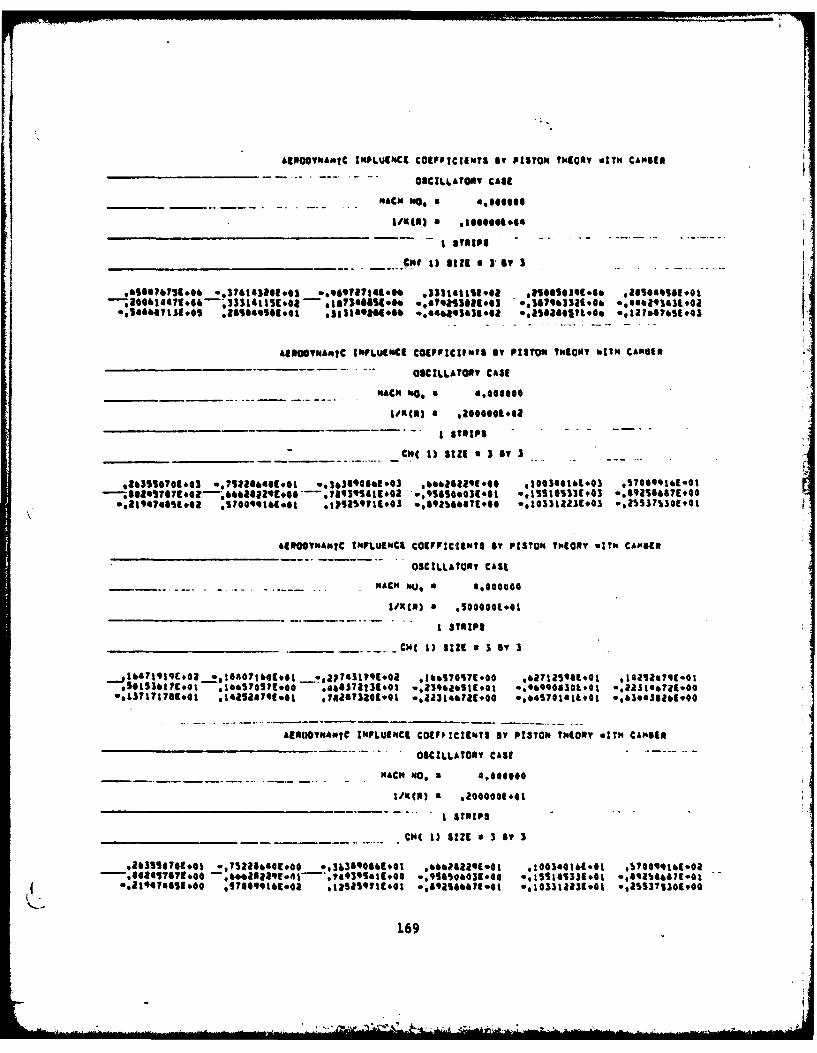
AEmoNA"Ic IMPLUINCEI COEFFICIET$? *w PISTON THEORY "It" CAMBER
OSCILLATORY CASE
_______HACH. 140, a 4,6OOOS
11 1) lif *[email protected]~
,&ss*?739*06o 0.S76143201943 0..99tRY1t.** *331111l.0ls - *Sa,.S1.,.4 *ao0o.,Sa,.o*t0061447E.4 '311e115.048 - 4g73e@8slose .,a?013429.03 .,17933l19960b .134 1 .@l Io~
*Iabai 1.5 *ea..ii .313140149.*& 0.462419100 esa58I8*II.0. .,II1?651.@I
AISowyNAMIC INFLUENCE CCIPP':C~IOI my PISTON THEORY k~N CAMUIS
__________________-____ -OSCILLATOY CA31
____________ ACN 40, a ,40060
S00009042
__________________Cht 1) silt a 3 0? 3
9203S10?@1*63 a.712866401*01 0036349061E03 6662622'0*@ 4100340169003 *5?0@I10
*.l~eseE.0 *70t~tC~I t15'S711.@3 0,4921be47t!.O [email protected] wZS537S301#@I
aawyOmAlotC IIFLUl"CI COEFFICIENTS BY PISTON THogay WITH CAMBER
OSCILLATORY CASE
H ACH IOU, a *000
I STRIPS
_______________________ 11I SIZE a3 mye 3
*5053t7..i *1A5SST~o *aa711.oI 16o9~S74179#4 *'62790I30I.@1 *.llSI*.?qclE
AERODYNSAMIC INFLUENCE COEFFICUNT0S BY P13TO. THEORY wITH CAMBER
-. OSCILLATORY CASE
MACH No, a 1008
I STRIPS
CHC 1) SIZE a 3 By 3
169
--~~~. ------. ..

1900400.03 FIN t00tI I I I PIN 10023 Pik 1 11
1,31b41O4.7e01eg,0.1,12~o~,O *62394t.O1 'a,000j71,05 S.AAaqoaOpjs 1 12QZ3~O391.05 6.62394[0O1 I,744s51,05.,*54283E*02.7. 7ha401.OS-.EZaE+O IPTN 1 13
019101211.05 Saal98L.00 6,26925.00l.7240c~ooao1.58011Og25020cople I t2,0000CE401 PIN RO0S
3 1 1 £ -Pift 200a3 PTN 2 11
S~S@S10as~oaagos,.so ~ fc £3a0. 1083.2I17&I0E-otPyk 2 121.609369#02 1,32479E#46 t.497621#02-1 9165111#413,[email protected]&E*OOPIN 2 13
*4.4tb'SI.01 1.176G4-1 2.S1570E.02.1:.48.00.2.074001,02s.12Oo1 OOP*. 2 145400400(.0 PrN 3001*
- 3 r- -i -----I'- - PIN 30023 PyN 3 It
3,lOI61I,01.7447o000. 31511.01 '3.31191C.01 1.24969E*01 2.940401-ORPIN 5 121.OO 4 49f0 11.10109310,0443E0-.ollo.,abo.11 3 L3*2060E #00.O 2.94099E-42 Ie5723IE#Ot-e ..4862og-o1.1.2q42cEOOI1.2taaEoO1, PT J 142, 00001.*40 PIN 4001
- 1 1- -1----------*-- PIN 40023 PTN 4 It
5.*50581.0.1.40g481.00_1.25041E.00 1.32479C-01 1.qqqO3c,00 1.1704ot-OaPIN 4 121.6QtSSC#OQ 1,32479E-41 1.SQ7821e00-l1S ~lf#00-3,10740E.00-I,7oaaAC.0OIPTN 4 13*4,G16'81.01 1.1764o1-0 2.5157CE.0o.1.79'&a801.2.07400-5o.,12400E1.OP 4 141 .00044L#03 PYN lo013 1 1-I - PIN 10023 PIN I i1*,y7q8E.05-5.00553E#.o1.2io0a1.O0 &*,3037E#01 3.3388SE*05 3.a5s31f*ooPINm I t2
-2,087SE0.o, 4.43o37E*0£ 2,49716F*03. A.39 26If*02-5.175021.O1.5.9651q1.OIPyN 1 13-7,33873E#04 3.854311.00 [email protected]& tO1.1.S~O0EO1.o5 .705l7E*02PTN 1 142,000001.01 PIN 2001
3 -- t , 't-tPTN 20023 PIN a 11
3,507190.02.00££IE#oI..,84273E.01 8'.11074C.e4t 1.3SSoE*02 7.708631.O2PIN 2 12l,0?tSOE#02 A,.aG4E.1948&.@-,7-t0.200?.2I.01C0P. 2 13*2,93549E*01 7.700&1o 1&3310-.Il2.0.,S0a,2..15s2oy 2 145,0000oOO PIN 3001
-.- 1--I--- - - PI 30023 PiN 3 It
2,19t9901.01.20741.00.3.g26711.01 2, 2I1tqc01 8,347131.00 1,927161.OIPIN 3 12-s,6960s1.oo 2,21IMY-o1 6,2I29tE,*00.3 19&34,00-123qt#01.2.fl2GE-O1.IN 3 1301.81'48EOo t,92716E.Gl 1.04b021.0t-2.O62S4&-01-G,&25I1.00.8,S23&-o1PTN 3 is__2,00000L.00 PIN 4001
3 t v* -. .. . .. . PYN 40023 PT14 4 It
3.571'.001.01£1,g..8.,3 1.. 860741.02 1.33554E.00 7.70831-O3PTIN 4 121,071%0tooo 8,860741!.02 6,64~.£17~10.~o07~o11s2.~ 13
-2.93549E-01 7.700431.03 1.?4E0..'l10.,308.03a03-1T 141.04000103 PN1001-. 3 1 1 1. . PIN 10023 PI It1
6,588771.05-.761431.02-9.09h271..1 333t11.041 2*SOOSOC.05 2,10t.*0PIN 1 12-2,006141#09 3.33:utg,01 1.s?3a01,0QS. , 7923102..8?031.05-.46e293g.01PTN 1 13
2.GGOOO E*Qt PIN 2001
3 PIN 2 Itl~s11 1.0l7.S21..00S~b80g.02 .*62b21-01 1.003401.02 S.740*961.2PVN 2 12
-2,1947S1#0t S.7@oqqg-oa I,2S264g**.0 9258V1.01-1.03312E.02.2.55J711.oOPTN 2 18S,000001.00 PrN 3001-- 3 1-----* *~ PIk 3002
91,371721.014to.1oo271O-.3.1-Io.li~o-.aslo~' 3 142000000E#40 PTN4 4001
3 1 1 1PIN4 4002
8,oleldl.-01 6.6612E21o 7.4930qf-Ol.0'1a8m061-01.1,13IA51.00-.9G,,lE1OPee 4 13ei1.10.711.0115,700041fOh41:1 170
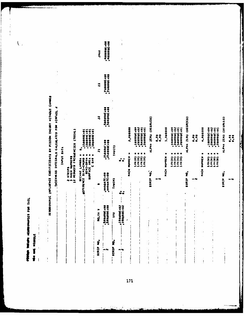
NOT 0
000
la 4D!
Ible
100O0
000 00
No ~ ~ ~ ~ t w m0t-I n
0o
W We"
o°p
00 0
Vs
.... _. 0- - - . .
0 U 0 9,0Q 6OO0 0 *A
P4 0 *,*0 W...0.. W...... .~
-. 0000 .@. ,40 0 4 @ ~ 0 00 A 0 U 0 0 . 0
00 00 00 00
- i0 0 i Ai AiA 4A
171
-ANII'I A _.W
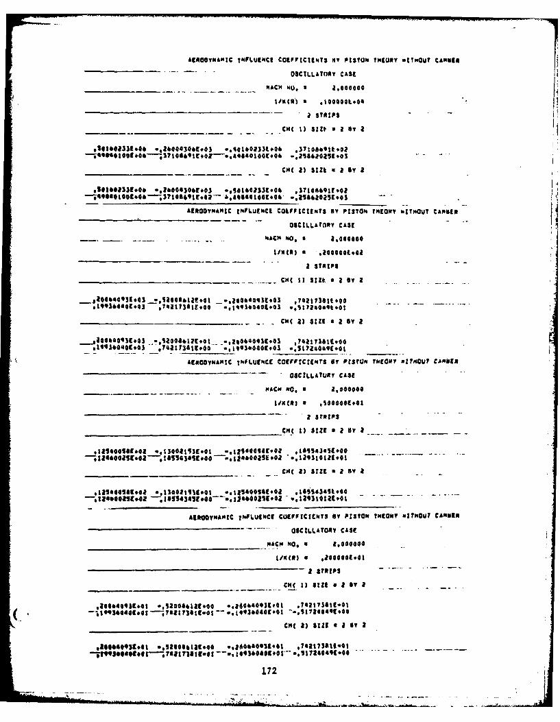
AgftOO'MIC INFLUENCE Casp~rtclgNT3 iST PISTONa nHIORY WITHOUT CANG-________ .-. -. OSCLLATORY, CASE
MACHNo. 2,10000.O4
-- _______a . STRIPS--
________ ________CMI 1) SIDt a a 6, a
____________CM( 23 SIZ. aS a yA
AEROAMIC tmFLUENC[ COLFFtCINT BY PISTON. THEORY WITHOUT CA1401M
OSCILLAtORY CASE
a STRIPS
________________CMI 1) SUEt a a By a
*19936440E.03 7481l73a199O0 6,1493604090O3 we1204to
-. __________ .2) -c( )SIZ~S a B
,io4eegqiE*os *.*l0QI*LlEot -120064093[#43 *?e7aIS99419,66449*43o 9742a113619*0@@ **993b44@(.3 *,[email protected] ______
AgpooyNAMIC ImpLUENce CoCFVirCIE*?s By PtSTaxrmG" WNOIuTHOUT CAMNEROSCILLAURY CASE
PACPS "a, a 2000
______________________________ CNS 1) SIZE a 2 By a--
*Iaseosu~o *.1OO15~E@t ,121400SSE*@a ,I84543451000
AKROOYMAXIC I.PLUENCl COEFFICIENTS Sy PISTON 115(05? WITHOUT CAMNES
OSCILLATORY CASE
MACH No, a 1,004000
Ii'S() * *00400E.41
__Cm(. 11 SIZE a 2 si a
( *UI*@JE*61 *.S20ooe12a00o 0,26@4644101 .742173619-41-.I9Se@0Ee0---Tel~la~.0t- .j492@401@I ..S1716@19t*4Q
CI 2) sizE a a By a
,iOO03K6 *eos606629#o .,204ea601gol ,?eIT73allool
172
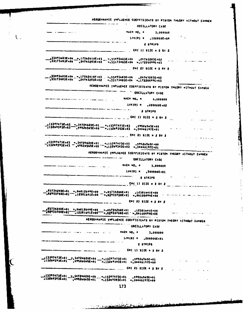
AgnQ@vkAMtc IHfs.uCCt COCFP!C?1WS By PITONe tP'SOPY WWOUV CANSO
OPCILLAI0IY CASE- - .. MACH g40, a @Oo
I/NC1 S .100040044
,-33it)d~js06. '247632419444 0,131734:39606 *.7a0,~3 -..--
Cut(8) 8IZ a oYI
ACNOTvwANh? INFLUENCE COEFFICIENTgSr st ISO, TN&Oty wtTNUUT CANSIII
-- - - G5C.DLMOus CASE
XACW NO.* .000
IoUcO) * .2OOS@01*42
a STRIPS
cu CS ) $12 SiE a IV a
cut 1) silt 0 a by a
ACNOOyTeagC INFLU14CI COEFIIENuTS NY PISTON4?"COST 011hOUT CAPIEN
- OSCILLATORY CASE
MACu Ig0, 0 3,@000
toot(*) a U 0044
- a STRIPS
_cm(uI1 SIZE 0 a my a__- .
&ENOOHAmC INFLuECE COEFFICIENTS IV PISTON MHORT "ITMOUT CAMOCS
OACILLArOa, CASE -
- MAC' 40, * 30000000
a STR~I
Cut iii 411 a by a
Cut 8) Sila amy a
1~33 01U?3I.01 e:SA41 tO0449* o4 *g13 97.i 3 101 4 1 6 g l
17 3
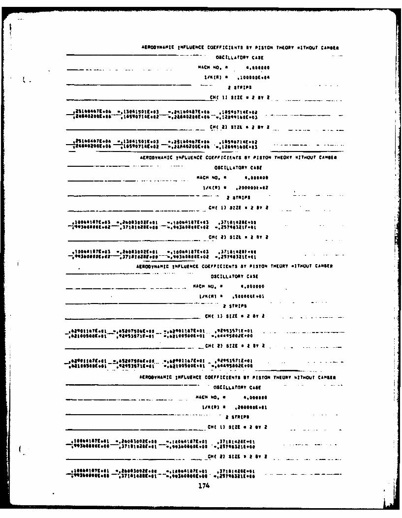
AISOSYNAMIC INFLUENCE cOEPFItCtlt.T By PISTON THEORY NITMOUT CAMBER
OSCILLATORY CASE
- -.- - - -. - -MACH N40.a doG
010000C *0
a STRIPS
CH! 13 SIZE a a IV a....-
*aie~eg~. ,isses,@iZ~os .,MO60?E7 # *IGSO071642o
*lI1&04071.e&C~ .2341@EGSC) SIlL a I BY I
£CROOMAMZC jNFLUINCE CO(FICIeNr3 By PISTON THEORYV WITHOUT CAN810
________-. -OSCILLATORY CASE
_________ MACH NO 0*.O@O
a $TRIP$
_______ CM 1 9 aE a IV 2
___________________ _____-CM( 23 StIL BY I T
- 1 0 0 6 4 1 G I C 0 0 3. 1 0 1 E @ . e ~ e O E ' 3 * ~ g ~ a ? o
A9ROOYNAMIC INFL.UENCE COEFFICIENTS BY PISTON THEORY aITiJUT CAMBER
OSCILLATORY CASE
MAC" NO, 4,000
a STRIPS
______ ______ ______ ______ CHC 1) SIZES Y a..2.-By- I
____ ____ ____ ____ ____ _ . CHC2) SIZE~ Y a. . . . . ..a
SEROOV"NMIC INFLUENCE COEPPICIINS IT PISTON THEORY WITHOUT CAMBIRE
OSCILLATORY CASE.1--
MAC" No, 0 4,400gg,
1W'U() 026494
a sTRIPS________________________ _ ___CM I)SIE a a T
*166'ISE.* *.~@S@6I.@@*.g9e'5?E040S41000E'h
174

I .~t~I43PIN. 1001* 1 I IPINs £001a ~PIN £I
~.gl~lIO~.aeog5l.l~q*Ib~(~fl;~?~i,.*I t's1IN-*,9**~g*~ 3tls~a~s1..'aO~p.I~l'0.I0.OlPt'ykI
PTNs10
_--PT% 111 -i
PT's 82I
1PT's 3 Il
f Piks GIa
l.OoOO~ooPT" 6001-*~ ~ ~ ~ ~ ~ ~ ~ ~~~T 8 £........-..-.- *---- P'4001
IPINS 4 1
41 1PINs 1001
_31 S~tl#o 2.47633.001-3.31731,S£ 710t0 - - .Pt's I l- a PINs I at3.3aG?C.i3 3lu4l**a3?.0l46S3E0 Ptll I za
~pt's 001P1's 1002
GPI a P' 11
aPt's ai -a!
1,11~~'4c,*a S*~~.1)3hs.33*Sa03E*0 PTM4 1 22S~oeoo.*oPIN. 3001
UPTN4 3 11
-0133711000 t.21T1tC.O-@1953 7 .0 .6.00St. PT'N 3 12a PIN 3 at
PIN 4001
S.ql6.GA PIN 4 %a
- 1 . - -. . . . . . . . . . . PIN 411a
44416 PINtoo[1
1.IOU.ge,0.fl@l1,1oO.O 1090P1*01 PIN6 I 1a8,46.010of prN0gO~l461.S..9'B0 It' la1
l.000 0pro$. pt' as~of's 8061
48 IPt's a It
aPtIN a at
1.0000.40PINs loot.S...j...j £ - ~PT's 301~~~1Pt's 3 it
-~1 . P's lla.,l*£l.0..,l.?~,.~.',a1.0 qa63,1,lPtIN 3 is*.I10166o ,893ogol~~ltoqI,0.ea49*1.1 .- - PTs 01
t. I PIN too&f~0Mig~q9.,~0034g.0.1.g04M*0 itllI.a~.*.9.9IWW~ ~ Pt'a
94 lome"Oft s~loo7o PN6lPTO 4 at
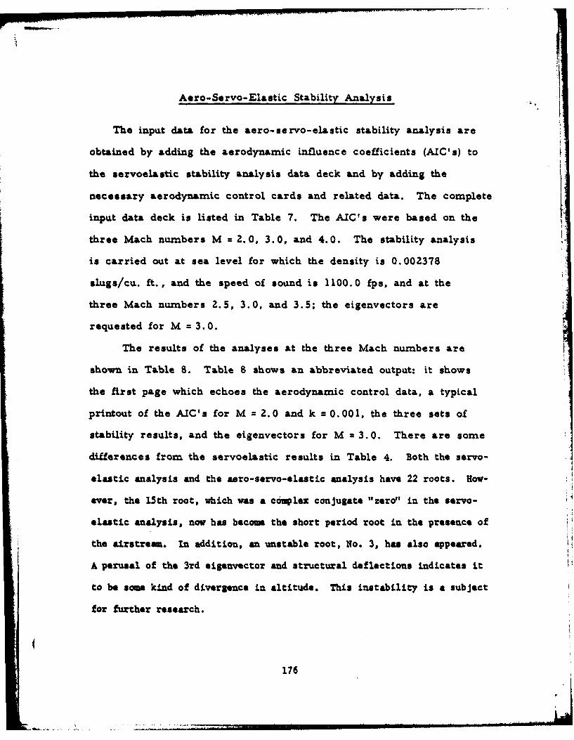
Aero-Se rvo- Elastic Stability Analysis
The input data for the aero-servo-elastic stability analysis are
obtained by adding the aerodynamic influence coefficients (AMC's) to
the servoelastic stability analysis data deck and by adding the
necessary aerodynamic control cards and related data. The complete
input data deck is listed in Table 7. The AIC's were based on the
three Mach numbers M = 2. 0, 3.0, and 4.0. The stability analysis
is carried out at sea level for which the density is 0.002378
slugs/cu. ft., and the speed of sound is 1100.0 fps, and at the
three Mach numbers 2.5, 3.0, and 3.5; the eigenvectors are
requested for M = 3.0.
The results of the analyses at the three Mach numbers are
shown in Table 8. Table 8 shows an abbreviated output: it shows
the first page which echoes the aerodynamic control data, a typical
printout of the AIC's for M = 2.0 and k = 0.001, the three sets of
stability results, and the eigenvectors for M = 3.0. There are some
differences from the servoelastic results in Table 4. Both the servo-
elastic analysis and the aero-servo-elastic analysis have 22 roots. How-
ever, the 1.5th root, which was a co0plex conjugate "zero" in the servo-
elastic analysis, now has become the short period root in the presence of
the airstream. In addition, an unstable root, No. 3, has also appeared.
A perusal of the 3rd eigenvector and structural deflections indicates it
to be some kind of divergence in altitude. This instability is a subject
for further research.
176
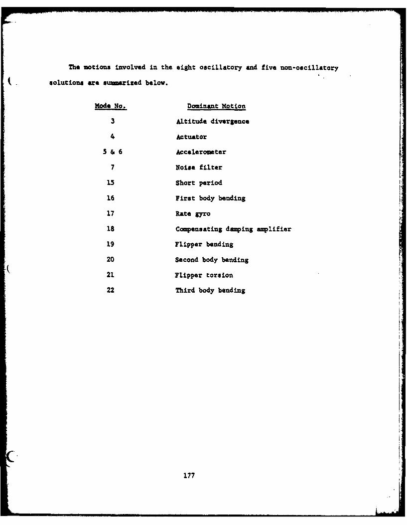
The motions involved in the eight oscillatory and five non-oscillatory
Ssolutions are sumarized below.
Mode No. Dominant Motion
3 Altitude divergence
4 Actuator
5 & 6 Accelerometer
7 Noise filter
15 Short period
16 First body bending
17 Rate gyro
18 Compensating damping amplifier
19 Flipper bending
20 Second body bending
21 Flipper torsion
22 Third body bending
177
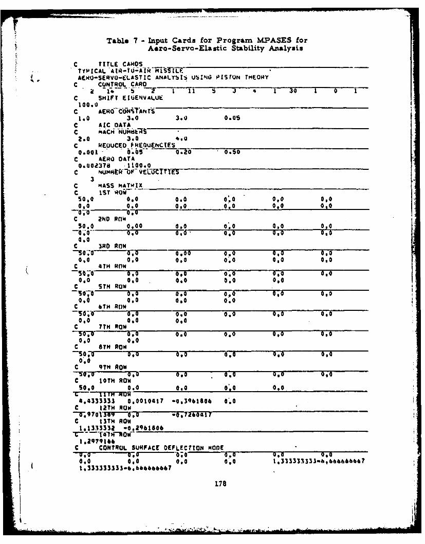
Table 7 - Input Cards for Program MPASES forAero-Servo-Elastic Stability Analysis
C TITLE CAROSTYPICAL AIR-tQj;'AH ML.AENO-SERVO-CLASTIC ANALY!)I UbING P[srUN THEORY
C CUNTROL CARO2 -1 - - 1 II 5 3 1 30 1 0
C SHIFT EINENVALUE100.0C ACOCN1A4T
1.0 3.0 3.0 0.05C ARC DATAC tAC' NUUkda2.0 3.0 4.0
C REW.ICED FREQUENCIES ______________________
0.001 0.05 0.20 0.0SOC AERO DATA0*002378 .1100*0
C NUM4HOFV ELCTTI-0-3
C MASS MATWIXC 1ST 'Odii50,0 0.0 0.0 0.0 0,0 0,00,0 0.0 0.0 0.0 010 0'00-;0 0oo
C 2ND Rnw50.0 0.00 0.0 0.0 0.0 0,0
00 0 0, 0,0 0,0 0,0.0
C SO 0 3RD RaW ________08___0________0__0___0__0____
-0o0 4 i00 0900 0.0 0'0 0,0
0,0 0.0 0.0 0.0 0'0 0.0C 0 TH ROW0-00 0,0 0.0 0.0 0,0090 0'0 0.0 0.0 0.0
C STH RW-070000 0.0 0,0 0,0 OV
0,0 0,0 0.0 0.0C 0 TH Row 0_0_ _60
50,U 0,0 0.0 0.0 0'0 0'00.0 0,0 0.0
C 7TH ROW pOt 0, 0.0 0.0 0,0 0p0
0.0 0.0C 8TH ROW
0,0C 9TH ROw-So 0 10 0. 0,5 0,0C 10TH ROWS0,0 0.0 0.0 0.0 0.0
4,4333333 0,0010417 -0,396806 0.0C 12TH Row_
9 7-03TV-, 0 0,u164417C 13TH ROW181333332 -0.2qb1806
1*2979166C CONTROL SURFACE OEFLECTION mODE
u.-To yU0 0 0.o 0,0 0 00.0 0.0 0.0 0.0 133333333ah,6b&6&66e?1,333333333-..bbabeo67
178
AMoak
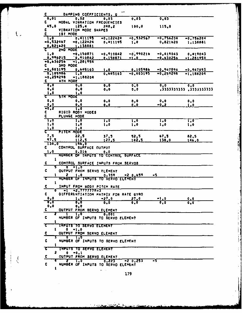
C DAMPING COEFFICIENTS, G0.01 0,02 0,03 0.03 0,03
C NODAL VIBRATION FREOUENCIES4S,0 12S,4 148,2 too 115,0
C VIBRATION MODE SHAPES. C 1St MODE
IO 0411195 -0,122424 0.S32567 -0.7s6204 -0,756204.0,532467 w0.122424 Og4111qS 1.0 0,821620 1,1388810,821620 1.13g88
T 2ND MODE1,0 -O.tSO871 -0,910842 -0.990216 -0.419043 0,4190430j990o1S 0,910842 0.150671 -1.O -0.63025b -1.2819 4
.0.60256 -1.2019s4C 3"0 MODEWO-03195 0.64S103 1.0 0.105916 -0 9 ?7894 -947893
-.IOslff 1.0 0.645103 -0.03195 -0,259298 -1,188204"00259298 o1,186204C 4TH MODE00 0.0 0,0 0.0 0,0 0,00.0 0.0 0,0 0.0 ,3333333333 ,3333333333
0_00,0 0*0 0,0 00
C RIGID BODY MUOEC PLUNGE MODEto 1.0 1.0 1.0 1.01,0 1SO ISO 1.0 1.o toS1.0 1.0
C PITCH MODE7.5 22's 37,5 12,5 67'5 82,597,5 1123 127,5 142.S 138.0 146.0
C CONTROL SURFACE OUTPUT1.0 0.016 0,0
G NUMBER O9 INPUTS T CONTR(L SURFACE
C CONTROL SURFACE INPUTS FROM SERVOS5 0 -100
C OUTPUT FROM SERVO ELEMENT1 2 1.O 0,359 -2 0,659 5
c UBER OF INUTSTOSRvO ELEMENT1
C INPUT FROM BODY PITCH RATE-0 . -,*77 778a3
C OIFFERENTIATION MATRIX FOR RATE GYRO0.0 10 o27.0 27.0 -1.0 0,0O00 000 000 0 0,00,0 0.0
C OUTPUT FROM SERVO ELEMENTa I IO 0,001
C NUMBER OF INPUTS TO SERVO ELEMENt
C INPUTS TO SERVO ELEMENT1 0 -1.0
C OUTPUT FROM SERVO ELEMENT
C NUMBER OF INPUTS TO SERVO ELEMENT'G INFUT3 TO 3ERVO ELEMENT
O OUTPUT FROM SERVO ELEMENTc NUMBER OF INPUTS TO SERVO ELEMENT
179
2 ,,. - ,* . , *
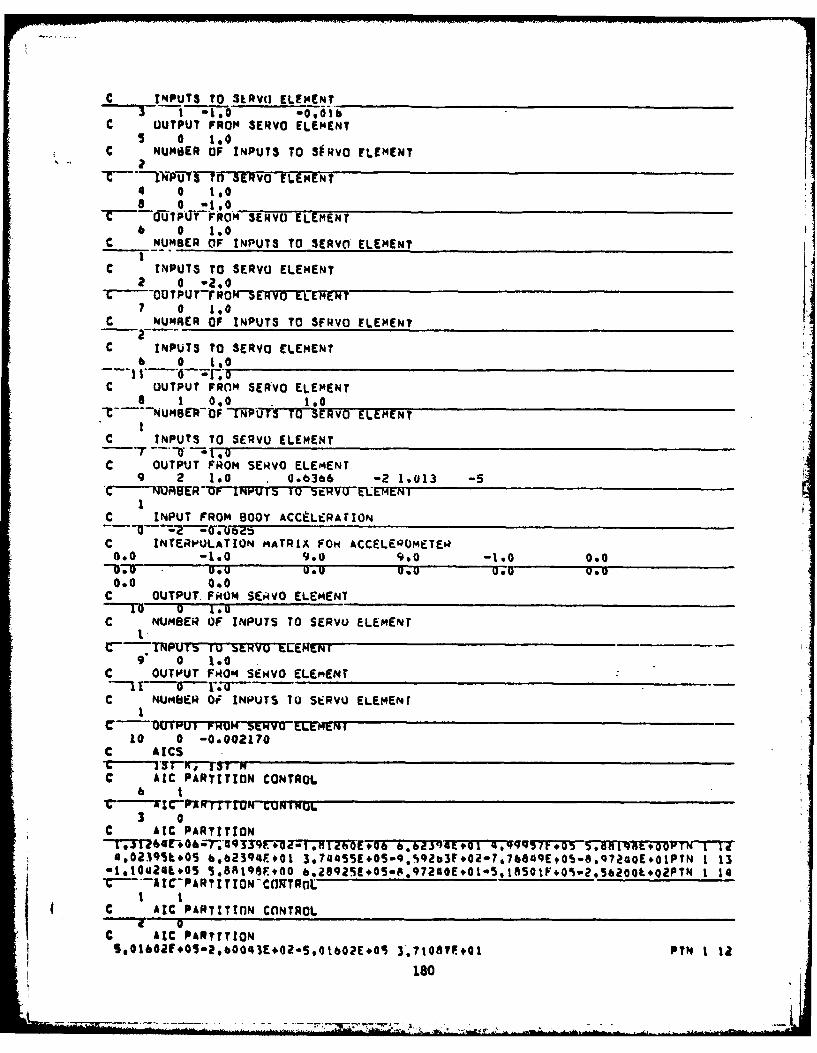
*C INPUTS TO SERVO ELEMENTI- 3 ,-i .. -0,O1b
C OUTPUT FROM SERVO ELEMENT5 0 IS0
C NUMBER OF INPUTS TO SfRvO ELEMENT
iikTPiFnSEVO FLEMENT4 0 1,08 0 a10lso__ _ _ _ _ _ __ _ _ _ _ __ _ _ _ _ _ __ _ _ _ _ _
O~OttPITFROM S9-ERVO ELEMENT6 0 1.0C NUMBER OF INPUTS TO SERVO ELEMENT
C INPUTS TO SERVO ELEMENT2 0 02.0 _ _ _ _ _ _ _ _ _ _ _ _ _ _ _ _ _ _ _ _ _ _ _ _ _
-C ur~ur sOTUTFOW-s rwiti-ErWT7 0 1.0
C NUMRER OF INPUTS TO SFRVO ELEMENT
C INPUTS TO SERVO ELEMENT6 0 IS0
---I ~ F~C OUTPUT FRnM SERVO ELEMENT
8 1 0.0 1.0oC -- NU,4@EWP-F TP'UT3 T"ERVO ELEMENT
C INPUTS TO SERVO ELEMENT
C OUTPUT FROM SERVO ELEMENT9 2 1.0 .06366 -2 1.(013 -5
C-- -WER OF IMPUtS 1U -ZWVVtL1tNI
C INPUT FROM BOOY ACCtLERAtION~207ii45
C INTERPOLAT ION MATRLA FOX ACCELE'QQMETEQ0.0 -1.0 9.0 9.10 -1.0 0.000.0 0.0 0.0 0.0 -070.0.0 000
C OUTPUT. FkOM SERiVO ELEM4ENT1 0 I~U
C NUMBER OF INPUTS TO SERVO ELEMENT
9 0 1.0C OUTPUT FROM SEHiVO ELE.ENT
C NUMBER Of INP~UTS 70 SERVO ELEM4ENT
10 0 -0.002170C AICS
C AIC PARTITION CONTROL
3 0C AIC PARTITION
4,0239SL401 6,62394E#01 3,744SSE,05-9.S92b3E,0a-7,7&eMQEtOS.eq724oEo1PTN 1 13-1910424E#05 5.88196FiO0 &.28929E.05-.t.97240E.01-5,1850lF,0i?.3e62O&.o2PTN 1 14
C AIC PAPTtTInN CnNTROL
C AIC PARTITION5.@1&02F.05m2,b0043E,0Z.5,016Q2E,0S 3'.71087P.#01 PYN 1 12
180
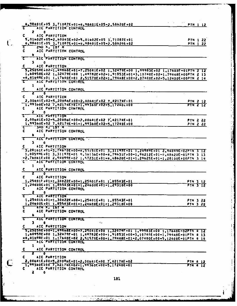
'a 9a01EO51 ItAE0-.60.E0-.~~f0 PYN 1 12c AIC PAR'T~fITIONCiONTRO-L
2 0C AIC PARITTIONS'01E,02EO5in2.bO3E+02w ,01b02E,05 3.71087E+01 PTN 1 22.4,98401aoE05 3.71087E,01.aq84o1E+05.p.S8620E,02 PYN 1 22
T -NO *k.TST -14C AIC PARTITIOIN CONTROL
C-AjtC--PRTflT N CONTROL3 0
C AIC PARTITION9,-i-58$E;02:f.-iq8b8E+01.7.2S0atE#02 1.32479E+00 1,99983E+02 1.1760 0PT4 2 12
1,609SSE+02 1,32479E+00 1,49782E,02-1.91853E*01.3.107U0E,02-1.7Qaa8EOOPTN 2 13w4,41bqSE,01 1.17b'40E-01 2.51570E.02-1,7944$E,00-2,07400E,02.5,124ooEOOPTN 2 14
C AIC PARTITION CONTROL
C ATC PARTITION I2.O0balr.02-5.20AhE+00-2,oobalr+02 7.G2t74E-01 PTN 212I '96E+2--,4-'--Z0 PIN 2 12
C AIC PARTITION CONTROL
-C ATC PlaIfrra2.,0Ob41E,02-i.2008bE,00.?.o06a 1EO,02 7.42174E-01 PTN 2 221.993bOE*02 7.42174E-01-1,99360E.02-5.l72a0E,00 PIN 2 22
-C 3RD (3C AIC PARTITION CONTROL
-c re, PATIToN CUNTROL3 0
C AIC PARTITION-3;2s1b1r,0'1-3;TUb70E+pp-4,51151E#01 3.3119YE-01 1,24989E+Ot 2,94099YE-OYPTN 3 12-1.00599E+01 3,3lt97E-01 9.16t3bE.0oma6.79E3IF,00.1,94212E,01-0i1aa620E-01PTN 3 13-2.760btE,0O 2.94099E-02 1,%7?31EOlw4.48620E-01-1,29625E.01-1.28100E+OOPTN 3 14
-- AIC-PiilfT'ZOW ON ROL
c IT ATTO OTO
C AIC PARTITIONCOTL
1,2S4OIP.01-1 30022E+00.1.25401FO1 l,.B55a3E-01 PmN 3 1QT.2oo~f5~Sao@24z600E+1-1 .93tOE~oo PTN 3 12
C AIC PARTITION CONTROL2 0
* 1.25401t.01in1.30022E,00m1,25401E.01 I.S5541E-01 PTN 3 221,2400E+..0 t.65'S43E.01.1.24600E*01.1..2931,E*00 PTN 3 22
-C--4TW T7TIC AIC PARTITION CONTRO3L
b 1G AIG PARTITION CONTROL3 0
C ArC PARTITION-57Z5I5RCT00i.'5c0op.,p908zE+00 1.32479F-01 t*99983E,00 1.17640E-02PTN 4 12-1,609M+E00 1,32479f-al 1,98E0-.lSE0-4170+0174R-IT a 13
w4,01b9Stae0 1,17640E-02 2,%1S70E,00.1.79445E-01-2,0740OE,00.5,12a4o E.0PTN a 14
C AIC PARTITION CONTROL1 0
*C AIC PARTITION2.0064tE+00-5,300A6E-ot-2 00641E+00 7'42t74E-02 PIN a 12
* 1.h0..217uo-1q93oE~o.5.~2qo~o1PTN 4 12C AIC PARTITION CONTROIL
30
181
AZ Z* A.- I
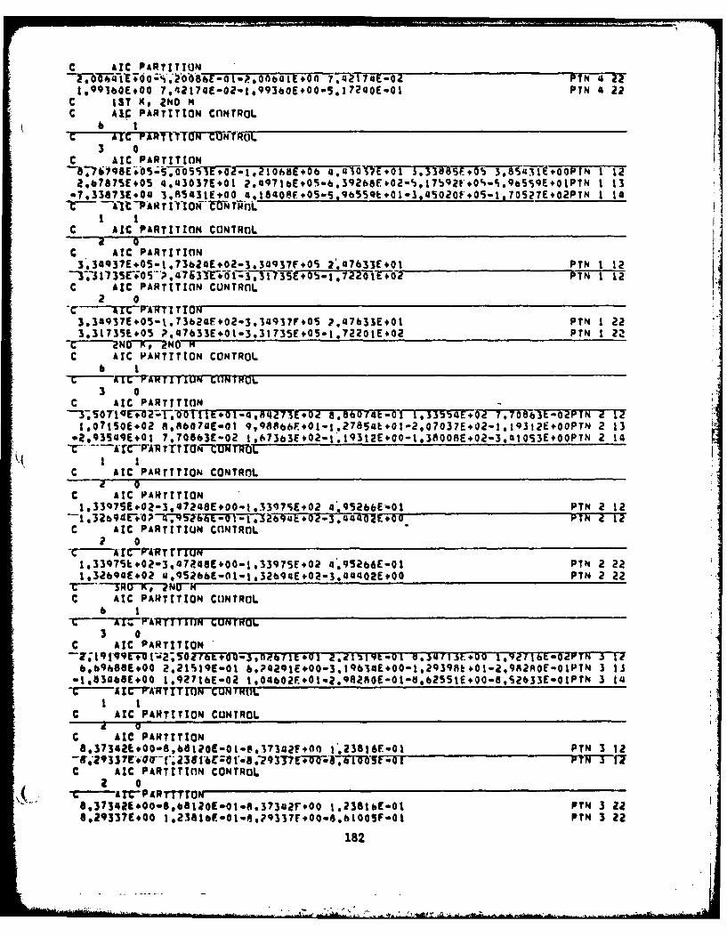
c AlC PARTITION__________ ____________________
f707&-R1iE;77zes-O4 PTN 'I 221,9936*E#00 7,42174(-02.1*993boE,00-5.172ooE-01 PIN 4 22
C 13T go 2N140C AIC PARTITION CflNTROL
C AtC PARTITION _________ ___________ _____
-,"71S .1 -T-O2 21 -b- .470- E*01 S.3388s5,O', 3.8MIT-OWPN 1 12'2,67875E+OS 4,u3037E+01 ?.aq71bE,05 6.39268F02-S,17S92F,0O%-%.9b5S9E.O1PTN 1 13e7.33a73E*04 3.R5431EgO0 4.18408V,05.5.9b5SQb,01-3,L15020F,05-1.705 7EO2PTN 1 14
1AI' 1P' A H"7 '*ZNr l
C AlC PARTITION CONTROLf
C AtC PARTITION
3'.34q31E.05-1,73b2oEO2.3,3493?F.05 2.47633E+01 PYN 1 12T3135~op~7~1Eiii)3Eo 1220VI +02 PTN 1 12 b
C AIC PARTITIOIN CUNTRnL2 0_____________________ _
AM FrKARTIT N ~r3,3G93?E.05-1.73b24F.02-3,3493?F,05 ?.47b33E+01 PTN 1 223.31735E.05 P,47633E.01.3.31735Ei05.722O1E,02 PTN 1 2
-C NU Xv NO-C AIC PARTITION CONTROL
6 1AM VAKrL11u149 GIJNTOL
3 0C AIC PARTITION _______
-3,0'q+02TO-TI+I4M2'E0 8.96074t-Of 1,3QE*077T9 L-OPTN 2 12F1.07t501.02 8,fl60?4E-Ot 9,A6E0-.75LO-,007+21132+O 2 13
o2,9354qE,01 7,70863E-02 t,67363E,02-l.19312E,00-1310O8E,02.3.aalO53EOOPTN 2 14
C AIC PARrITION CONTROL
C AIC PARTITIONI.33Q751.QZ-3,47?4aEiO0-t.33975E.02 0*.95266E401 PTN 2 12
C AIC PARTITION CONTROL
-C' AreP-ARTrr LUll1,3397Q.#02-3,47a4aE1.o-1.33975r,02 4*.95eb6E-01 PTN 2 221.3269GE402 4,9S2&6E-01-1,32694E,02-3.44402E,00 PTN 2 22
C AIC PARTITION CONTROL6 1
* t~t~PA RzITUM CU14TKUL3 0
C AIC PARTITION _____________________
6.b9h8aE#00 2.21%~19E-01 bP4291E400-3.19614E,00-1,2939Rk,01-2.9R2AOE-QlPTN 3 11-105306a1+04 1.927tbE.02 1.0U602F.,01.9.82R0E-01-d.b2551E,00.8,S2633E-G1PtN 3 L4
C AIC PARTITION CONTROL
C AlC PARTITION8.373421,00.8,66120E-01-e.17342!,OnI 1'23816E.01 PTN 3 12
-- r29337E.Q4rr;--23lti6rZ0 P-8 3?37 12.7T~5 0C AlC PARTITInN CONTROL
6.373421.00-6.08120E.01.8.373027.00 1.238tbE-01 PIN 3 226.293371.00 1.23a16E-1.o..9337r+oo$e.bIOOSF-o1 PIN 3 22
182

C 47HK, ?NOM 7TTICPC rWR T TfON CONTROL
I PATTO OTO
C AIC PARTITIONCNTL
'TS7i9E;oo.1.-;op6fIT+-TbO-4,84273E+00.A7Q-21335s.0 7,70863E-03PTN 4 121,07150E+00 8,86074E-02 9.QRR8ebF-O1-t.?7$S4E100-2,07Oi7F,00.1.19312E.0IPTN 4 13
%2.935 9F-01 7.70863E-03 t h7363E.00-1.19312EZC-l,3008E00-3,QIO53EOI3 TN 4 14C A I CP A R fIflONhCU TRtlL
C AIC PARTITION C(lNTROL
C AIC PARTITION1.133q7SE00.3.47248E-01-le33979F.00 4*.952bbf-02 PIN 4 12
---.32 69 4EM0 0-T.-952 6 SE- 07Q * b 01 P fTVT-C AIC PARTITION CONTROL
1933975E.00-3,47208F-a1-1.139?5FO0 4.,95266E-02 PTN 4 22
C AtC PA4TITION CONTROL
C---AIr PARTITION tNTMOL
C AIC PARTITION ________________________________38~7ET8377T4~~o29,o7z7~o53.33141E+01 2.50ME+.05 2,85050F*00ptN 1 12
2.00614E+05 3.33141k+01 1 ,873iaE.05-a.?92sJr.OZ-3.87963E .Ob-o.AzA293EO1PtN 1 13-S.48687E*OG 2.85050E+00 3,I314qE.05"0.46293E.01-2.58281E,05-1 ,2lb8SE.O2PTN 1 i4-CkI-ICP RT TMW7iCONTROLC-
I IC AIC PARTITION CONTROL
9 0C AIC PARTITION2.516OSE+OS-1.304t5E#02-2.51605E*05 1'.659O71.01 PUN 1 12
--2,3-40E:;S-T7S9-6F.+l-,7, a~?E+50j,9992#zP T N 1 127C AIC PARTITION CONTROL
2 0
2.51Ei05E405-1.30415E*02-2.51&05E.05 1h8 907E+O1 PTN 1 222.48402E+05 1.8 907E+01-2,48402F,05-1.?8992E.02 PTN 1 22
A,3RC AIC PARTITION CONTROL
-C- IC' PARTITION CONTROL3 0
C AIC PARTITION~E331ETO7R~si>.o-3,1eo1~o26,66282E-01 1,00340E+022 5,7OO49E-02PTN 2772
8902458Eg01 6,66202E-01 7*aaq34%E.1. 158~bE.00-1,S5185E.2O2..258?E.01PTN 2 13-2.194751,01 S.70099E-OZ 1,2S2eoE.02.- .92587E-01-1 *0331?L.02-2 ,55375E+OOPTN 2 14
C AIC PARTITION CONTROL
C AIC PARTITION1.0Oh42E.O2-2.E,0830E.00-1.0064?F.02 3.7?1814E.01 PYN 2 12
-991OFTr a PVN 1 12C AIC PARTITION CONTROL
a 0~~~~PATfI TION
1.00a42E*G02-2.boR30O.OO-1.OO642F,02 3.71814F-01 PTN 2 229,9360101 3.71814E-01-9,93*,OSE,01.pS?983E.00 PTH a 22
c AIC PARTITION CONTROL
183
Zia,~
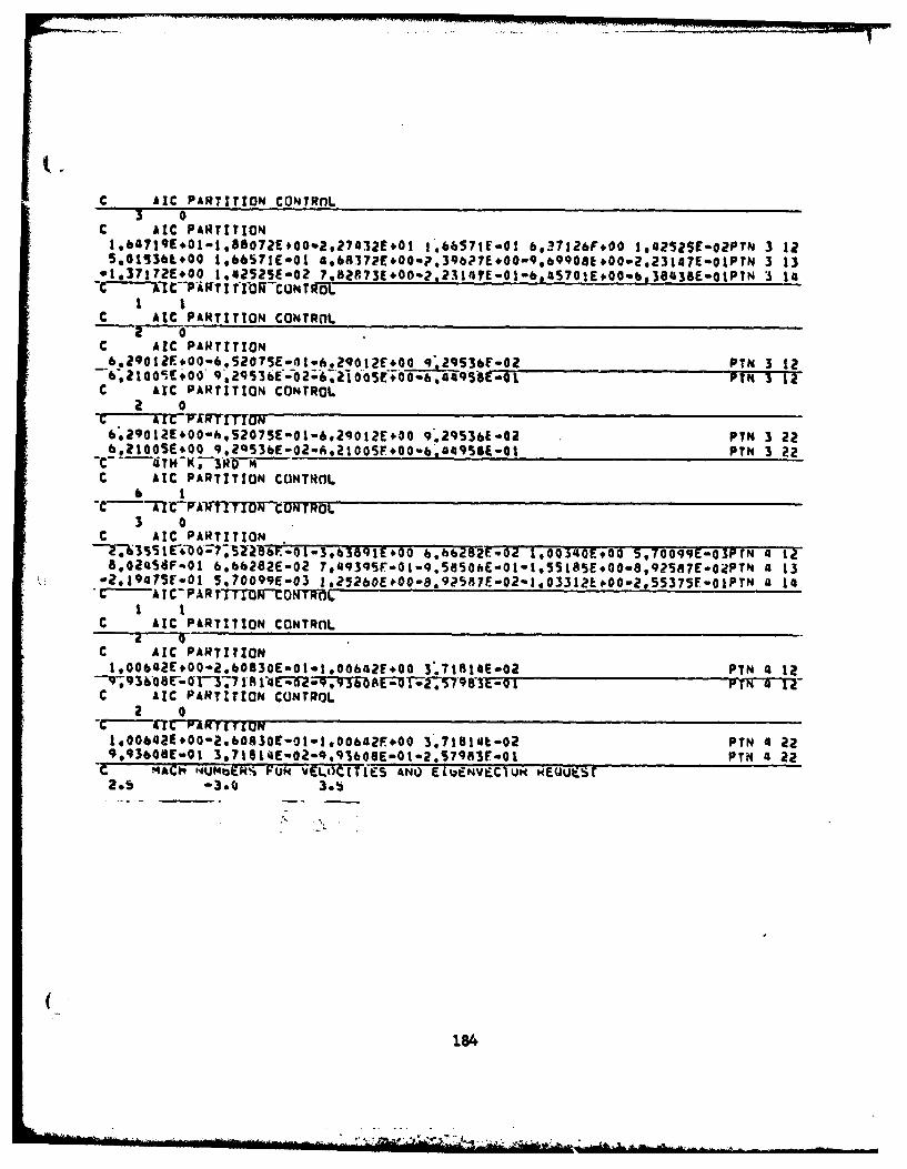
C AIC PARTITION CONTRnL3 o
c AIC PARTITION1,41E0-,87E0%,73E0 1'.66571fo0I 6,2~7126F+00 1..?sZSE-02PTN 3 12S.OI536t.OO 1.6S'TlE.O1 49&A372E#00.m..39b??E7I,OO9b9q8&,OO2,23147E-OIPTN 3 13-1,37172E+00 1.aa2SZ5E-o2 7.2710-,34E0-,4?I+0b34$-IT 14CTIPWI 1IbFFCONTO0L-I I
c AtC PARTITION CONTROL
C ARC PARTITION*-.91E0-.~~~~_62o~~o2-q~f0 -PTN 3 12
6121OO, +,OG FTPN 3 12C ArC PARTITION CONTROL
t~rrARTTIONb.29012E.Oo-hS2075E-01-a.29o)2E*oo 9.295361-02 PTN 3 22b.21005E+00 9,2QS36E-02-6921005F+00-6 449SAE-01 PTN 3 22
-C 4TH -K ;3 RWWIC AIC PARTITION CONTRnL
-C lPXT VIT T ON F N TROL3 0
C ARC PARTITION_________________________________rl63SE40;?,Z2-F0-.39Eo b.bb2a E-02 1,00340E*00 S,700qgE-O3prN '4- IZ8,024I58v.01 6,66282E-02 7g9qF0-.80E0-.5IS*089S7-2T 4 13-2.1947SE-O1 5.70099E-03 lo56E0-.?aE0-*032*02535- T '4 14* C -A IC-PAR rTTMWtONMwdL
I IC AIC PARTITION CONTROL
C AIC PARTITION1,00b42E.O0-2.60830E-01-1.00ba2E,00 3.718l4E.02 PN4-2
C AIC PARTITION CONTROL2 0
*- -AC Cr r P( r I LOPE1.00642E.00-2,b0830E-01-t.OObGZF,00 3,7181iGt-02 PIN 4 2290936E-01 3.?1S14Eu02-Q,956o6E-01-.S?9783r-Qj PTN 4 22
c 4ACi -NUMa~ks- PL* VELOUCTLES ANO EWl.,NVECIUNREUEST
184
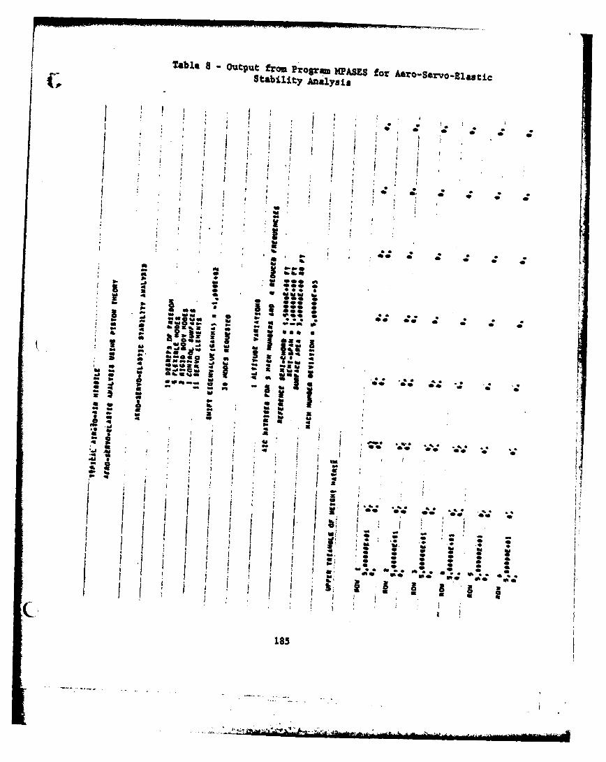
Table 8 - Output ftrou Progm NPASES for Aero-Servo-ElastLcStability Analysis
I I
Q r
a * A a
,! I * I
t:I 5
-I I 0 0 °a * , - . -X so
4 1
1* 4 o U,,,4*- -i I. *n- *i l l m
.t " -l II
; : i *g
L ' 4' 4'5 3bass !
4' 8e
• -a ...- . . -
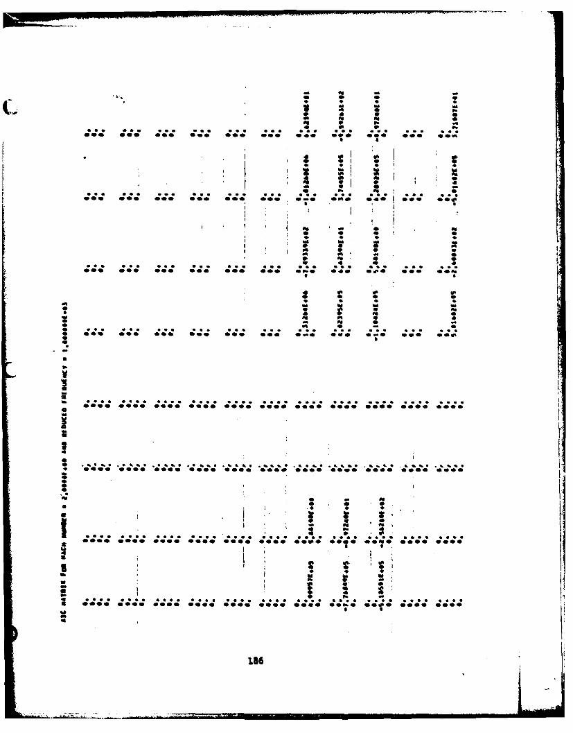
WII
1C S p
ftN
A 0
* 4 41
ft5
0. *JJ
.*6* %4* a. a,.*0 4000 0 40 00 000 *000 000.; '00,4 '000 000:0 .
* 0 50
;ZI: 4z; :4;Z:: ft* -0O00 00
1866
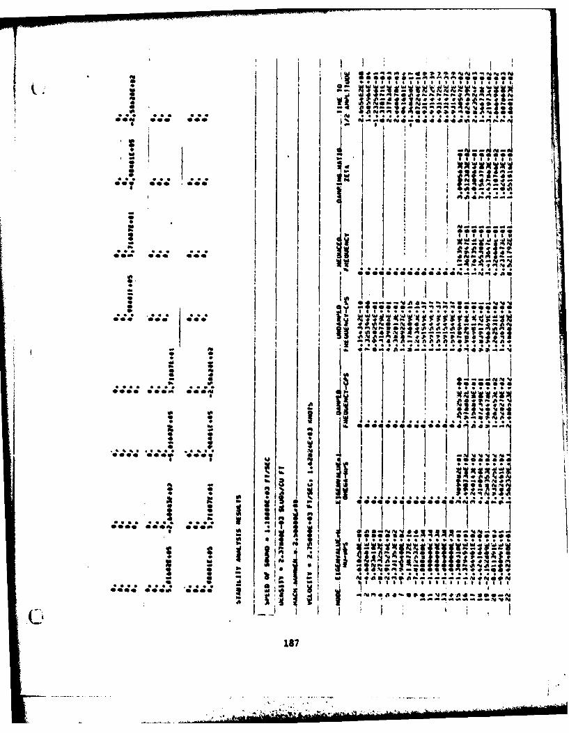
*NOVO-4 44 ... aam. 4qf--
* - *A'aqu ~ .q v - kw
*~~ 0 Ij 4; *W
q?0 C PA 0* a-t a .1 It4 SA ,
4 j4ai
I ItI. W.. 0* 00 06 0 AI A40g' *
0000e.e..0004a.4-A ow A
I~~~ T ~4
a I , I000-
*~~~~~~' 04 a -0S4- ~ a j
0040 0000 00 2
I... 187
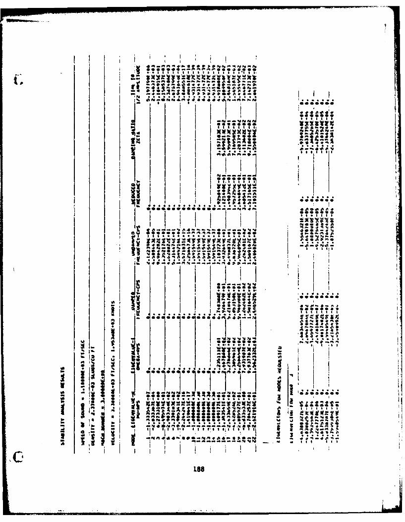
44047i4EqEEU4*4 i l-Ef
.0 4 Of% * 10
.. Alft ~ ~ of 5* .*Ansa
to~@6 0 i--
*~ ta Sof
A'A ~ -4 -4
*4*** 5.. .... 5oil
I Z Ift ft-e4
4Al0 I8 Al aIla60
. - SAgI ~ ~ ~ * .oi I* 11 .1 1 $ 1 ;1 1 1 0
~188
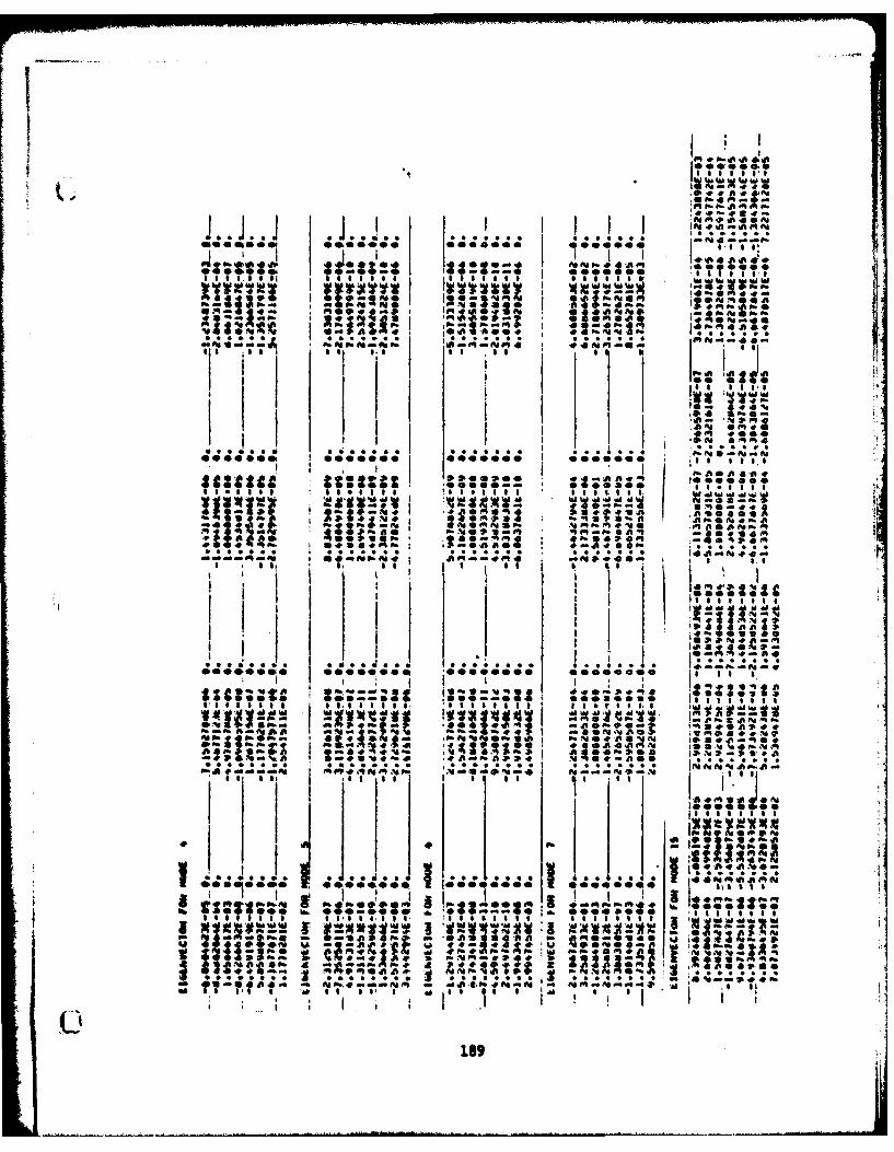
1,44I S ftS
I If I* on1,a*,.e~ Olt0 j 0400 00 0 0e 411
E~4i
Iq 1- 0 ia oI a:. 1 10 IV S % : r . "I I1s P,* s sI
ft 0 * * ft Ib ft0" 4 t
9 IdI
.SSt *!;Sm : T -4 - t.V
w AM ow ft
Z,... P' a.. * oft"*. . **
M~ ORMgN-g"
C11- *e0~I0~~Ae
-~ 189
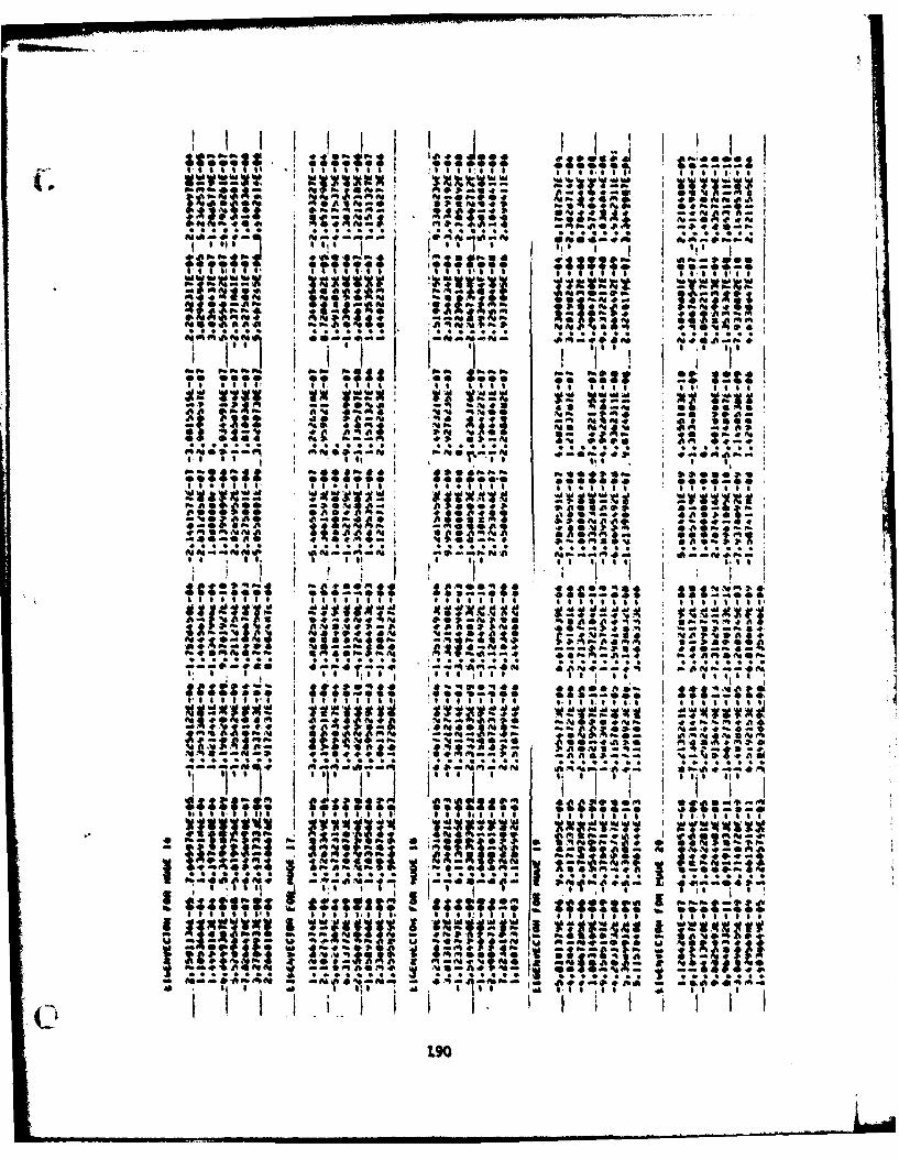
1 4 1 114 ~ ~ ~ aA 0 6 1 * .
~ Ia WOO Po -V 4P.
ltI s I. $ifS. ftg S P.40,40,I 111111101S ;1" *0 "
08 -.1
Z 20* JI,0 R . %
ow lose S *d.2 ~
S. I. S t . .; . j t~ I,
I I & a TO I
*s--.-* *4 SaO-- *ftP. it "01H 5 lSSt
I ~ ~ ~ ~ Z 5 SSBS e sss*s a 0 18.:00 is PE~0~~ ~ d.4:H- 04A0 Oto
1VIAIs*. 0* of '0 up. ft * 4 #
A* 9* ;. ; P.7 i0
A 4*- 40 ft
T. -II IS oil'61me 1
I4 so~ v I; ft if** ' nil '-S m.t f4 a -.4 s
tsszftsFit a.fS~
at I 10 0 1 1 1 1 a I0
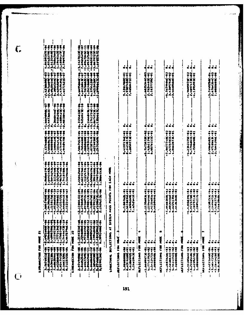
:0 00944 Go we J
AliAi~i 2#0P* Al Go-I.W*1 aw1K 0P.44P
SU M: 22;,TT"T00 a00
jgvvxp jjq;Vxa G
I I . pa
SM P." 1 .I a II, IS
1 000 *eo 0 0 104!0a SoI aggg*TT1 11 1 11 1 1 oil o f f
P.1 000 :0I -210000
I I fi
i In~KiGf -. I.Go, 114P @&m'4aK
np.-~ 4Fq6~ - k i..* *~~I n o * .* * * -* 4
I .dl : 1*U1- - 11Reafi~~~ao
1 11. ~ * *
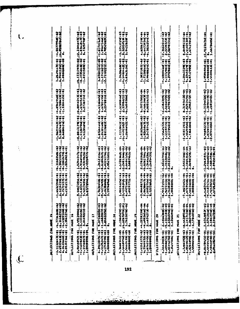
.. . . -. ... . - = -, , +
-- . . . . . .
:~~ ~~ 01 0 l
t1 I II I I I It, I
AJ 04 Ift J
=ff -r .0 -O10O O'sO
0o0 =o : so""
-t 0 it' ' '' °, !" , ! i , ,
,,, 1,. 111 ,| 01 1 C, $10 71640
O4v O r
40AI *.o ! :- P1
dp 1
NO# 4ee0 V olee11 Jil IIl 01 t a S, 0-0 1| ' I ft I 1 11
NAA 610 fm1
Jil itH I : o4p
loldn I -a- ft Nis2? -ft ap-
0.... @.... .... o.0 . ... I oo.. 0o..I ...0I , II III , fI P' I' I I + ~ ' II,;I I
!( ----I *I 2 ,
0 0 0 0 0 1 00 - - ...
1:i 2:. 40 1 1 lo Is. vr- OI I; I I of1
!A 0
4~ A.,~ Id 1:9 1 . ., ~ 0 f.49.4*p ;. r-4. 400% v It.* ;
ft4 I454 'a25 pal 't* ~ l
I I II *. I z I 1 1 11
'a0 ,** ot 1 .i0i *5 tlq
00.1 MPi On III VA at 0 1 1 I IftS
A*t1 '*P PP4- Ai@ @40 0.-
Ala.. V.1i4 to:. 114
ft' 20feISI. t105 **.1 -1 T* T' * 9 2
if vt **49m I' a91~ .4ISIi 4 ..
I IF
-0,1 61.001.16 44 1.14
' ~ f -V? 0 4 b 7?0.0 . me 7?'?? *&*O* 6 011_*SO
41PA. ft ,. P. [email protected] on.5 rS i*A0 .Ul i
2
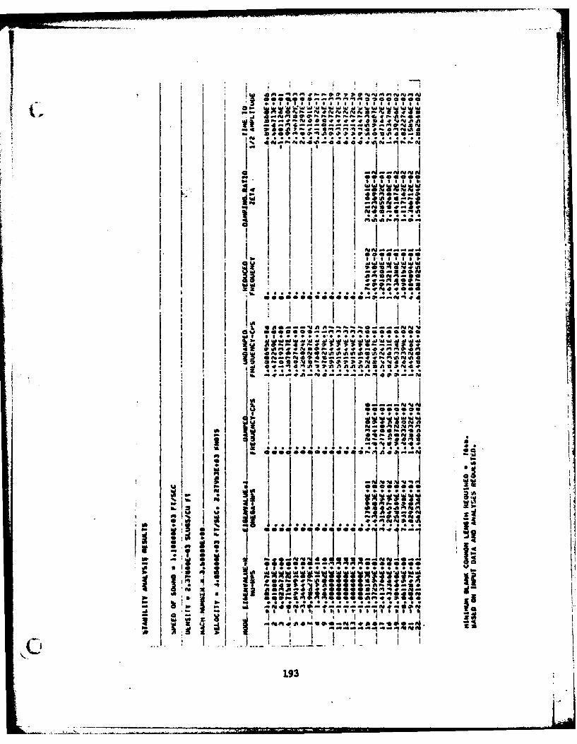
I a it
48W~~ ~ 845 20"l~ ,t E 4
4.004.4.4Eed0iISIA
v I
gx 0400 0 a... a 00 a
w pa 2* a* * a
op 1 1 8
saleg1g
0 0a
i ooe oee oo ee*0E qooo o
ItI3b -0 op. Md .WMW4 .E .4 .I ...
1 I "lllMH
3ww I
! 193
" a-
• I I ,E tO, l$
-|.. i. _. I ..-... a .. .. * a ~ * .. a... { I I+
~ I !~V .

SYMBOLS
In this modification to the original program PASES, the general
notation has been retained. The nomenclature used in the basic develop-
ment (Ref. 1) has been reproduced in Appendix A. The new symbols intro-
duced in the present modification are defined here. The reader is referrea
to Appendix A for the definitions of symbols not appearing below:
A Coefficient in spline fit, Eq. (57); also see Appendix A
a0 ,a1 Coefficients in spline fit, Eqs. (67) and (68)
B Coefficient in spline fit, Eq. (S7); also see Appendix A
br Reference semichord
C Element of discrete damping matrix; coefficient in splinefit, Eq. (57)
C Element of generalized damping matrix
if.- Ch Element of oscillatory AC matrix
ChDh Element of dauping AIC matrix
Imaginary part of
ChR Real part of Ch
Element of static AIC matrix
c Reference chord
D Coefficient in spline fit, Eqs. (57) and (60)
E Modulus of elasticity
f Cyclic frequency
g Aeroelastic damping coefficient
I Element of unit matrix; spline bending moment of inertia
Ikj Element of spline interpolation matrix, Eqs. (74) and (75)
Ct KjiKkj Spline parameters, Eqs. (70) and (73)
K Element of generalized stiffness matrix
194F
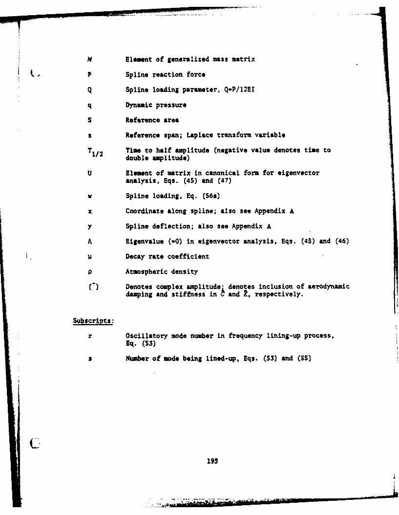
N Element of generalized mass matrix
• P Spline reaction force
Q Spline loading parameter, Q=P/12EI
q Dynamic pressure
S Reference area
s Reference span; Laplace transform variable
T1/2 Time to half amplitude (negative value denotes time todouble amplitude)
U Element of matrix in canonical form for eigenvectoranalysis, Eqs. (45) and (47)
w Spline loading, Eq. (56a)
x Coordinate along spline; also see Appendix A
y Spline deflection; also see Appendix A
A Eigenvalue (-0) in eigenvector analysis, Eqs. (45) and (46)
V ii Decay rate coefficient
P Atmospheric density
C) Denotes complex amplitude- denotes inclusion of aerodynamicdamping and stiffness in b and k, respectively.
Subscripts:
r Oscillatory mode number in frequency lining-up process,Eq. (53)
s Number of mode being lined-up, Eqs. (53) and ($5)
I
195
REFERENCES
I. Anon., "Modal Flutter Analysis Study; Vol. IV, Aero-Servo-Elastic
Stability Analysis Program: PASES," Rpt. No. SD 15204R, Hughes Air-
craft Co., April 1971.
2. Jocelyn Lawrence, A., and Jackson, P.. "Comparison of Different
Methods of Assessing the Free Oscillatory Characteristics of Aero-
elastic Systems," British A.R.C. C.P. No. 1084, 1970.
3. Rodden, W. P., and Revell, J. D., "The Status of Unsteady Aerodynamic
Influence Coefficients," Inst. Aerospace Sci. Paper FF-33, January 1962.
4. Anon., "Modal Flutter Analysis Study; Vol. I, Subsonic Strip Theory
Unsteady Aerodynamics Program and Supersonic Piston Theory Unsteady
Aerodynamics Program," Rpt. No. SDIS204R, Hughes Aircraft Co., April
1971.
S. Giesing, J. P., Kalman, T. P., and Rodden, W. P., "Subsonic Unsteady
Aerodynamics for General Configurations; Part I, Direct Application
of the Nonplanar Doublet-Lattice Method," AFFDL-TR-71-5, Part I,
November 1971.
6. Funderlic, R. E., and Rinzel, J., "ALLMAT, A Fortran IV Arbitrary
Matrix Eigensystem Solver," SHARE Program Library, SDA No. 3441,
2 March 1966.
7. Anon., "Computer Subroutine Libraries in Mathematics and Statistics,"
International Mathematical & Statistical Libraries, inc., Houstin, TX,
November 1977.
8. Wilkinson, J. H., The Alaebraic Eiaenvalue Problem, Oxford: Clarendon
Press, 1965.
9. Cunniugham, A. M., Jr., "EIGNVCT, a Subroutine to Obtain Elgenvector
from Real Non-Symmtric Matrices for which the Eigenvalue is Known,"
General Dynamics, Pt. Worth, 1973.
C 10. Harder, R. L., MacNeal, R. X., and Rodden, W. P., "A Design Study for the
Incorporation of Aeroelastic Capability into NASTR iN," NASA CR-111918,
Xay 1971. 196
11. Rodden, W. P., "A Method for Deriving Structural influence Coefficients
from Ground Vibration Tests," AIAA J, Vol. 5, May 1967, pp. 991-1000.
12. Rodden, W. P., Parkas, E. F., and Malcom, H. A., "Flutter and Vibration
Analysis by a Collocation Method: Analytical Development and Computa-
tional Procedure; Appendix B, The Transformation of Inertial Data into
a System of Lumped Masses," Aerospace Corp. Rpt. No. TDR-169 (3230-11)TN-14,
31 July 1963.
197
![Time domain aero-thermo-elastic instability of two-dimensional … · 2020. 11. 3. · and Khala˝ [32]esented a numerical analysis for the aero-thermo-elastic behavior of functionally-gr()](https://img.pdfslide.net/doc/110x75/60d9ab8ca83c673d7a7c3fa2/time-domain-aero-thermo-elastic-instability-of-two-dimensional-2020-11-3-and.jpg)