Embed Size (px)
DESCRIPTION
Porsche Cayenne engine repair
Citation preview
AfterSales Training Cayenne Engine Repair – V8 and V6
P10C
®
Porsche AfterSales Training
Student Name: ________________________________________________
Training Center Location: ________________________________________________
Instructor Name: ________________________________________________
Date: ___________________
Important Notice: Some of the contents of this AfterSales Training brochure was originally written by Porsche AG for its rest-of-world English speaking market. The electronic text and graphic files were then imported by Porsche Cars N.A, Inc. and editedfor content. Some equipment and technical data listed in this publication may not be applicable for our market. Specifications aresubject to change without notice.
We have attempted to render the text within this publication to American English as best as we could. We reserve the right tomake changes without notice.
© 2007 Porsche Cars North America, Inc. All Rights Reserved. Reproduction or translation in whole or in part is not permittedwithout written authorization from publisher. AfterSales Training Publications
Dr. Ing. h.c. F. Porsche AG is the owner of numerous trademarks, both registered and unregistered, including without limitationthe Porsche Crest®, Porsche®, Boxster®, Carrera®, Cayenne®, CaymanTM, Tiptronic®, VarioCam®, PCM®, 911®, 4S®, andthe model numbers and distinctive shapes of Porsche’s automobiles such as, the federally registered 911 automobile. The thirdparty trademarks contained herein are the properties of their respective owners. Porsche Cars North America, Inc., believes thespecifications to be correct at the time of printing. However, specifications, standard equipment and options are subject tochange without notice.
Part Number - PNA P10 C03 Edition - 6/07
Table of Contents
Cayenne Engine Repair – V8 and V6
Description Section
Engine Type Designations . . . . . . . . . . . . . . . . . . . . . . . . . . . . . . . . . . . . . . . . . . . . . . . . . . . . .1
Cayenne S and Turbo V8 Engines – 1st Generation . . . . . . . . . . . . . . . . . . . . . . . . . . . . . . . . . .2
Cayenne V6 Engine – 1st Generation . . . . . . . . . . . . . . . . . . . . . . . . . . . . . . . . . . . . . . . . . . . . .3
Cayenne S and Turbo V8 Engines – 2nd Generation . . . . . . . . . . . . . . . . . . . . . . . . . . . . . . . . . .4
Cayenne V6 Engine – 2nd Generation . . . . . . . . . . . . . . . . . . . . . . . . . . . . . . . . . . . . . . . . . . . .5
Conversion Charts . . . . . . . . . . . . . . . . . . . . . . . . . . . . . . . . . . . . . . . . . . . . . . . . . . . . . . . . . .6
Cayenne Engine Repair – V8 and V6
Engine Type Designations
Cayenne Engine Repair – V8 and V6 Page 1.1
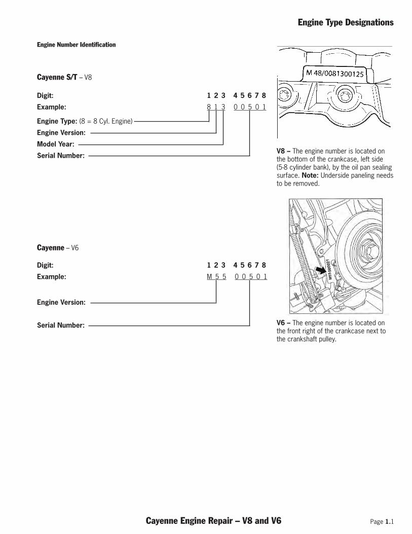
Engine Number Identification
Digit: 1 2 3 4 5 6 7 8
Example: 8 1 3 0 0 5 0 1
Engine Type: (8 = 8 Cyl. Engine)
Engine Version:
Model Year:
Serial Number:
Digit: 1 2 3 4 5 6 7 8
Example: M 5 5 0 0 5 0 1
Engine Version:
Serial Number:
Cayenne S/T – V8
Cayenne – V6
V8 – The engine number is located onthe bottom of the crankcase, left side (5-8 cylinder bank), by the oil pan sealingsurface. Note: Underside paneling needsto be removed.
V6 – The engine number is located onthe front right of the crankcase next tothe crankshaft pulley.
Page 1.2 Cayenne Engine Repair – V8 and V6
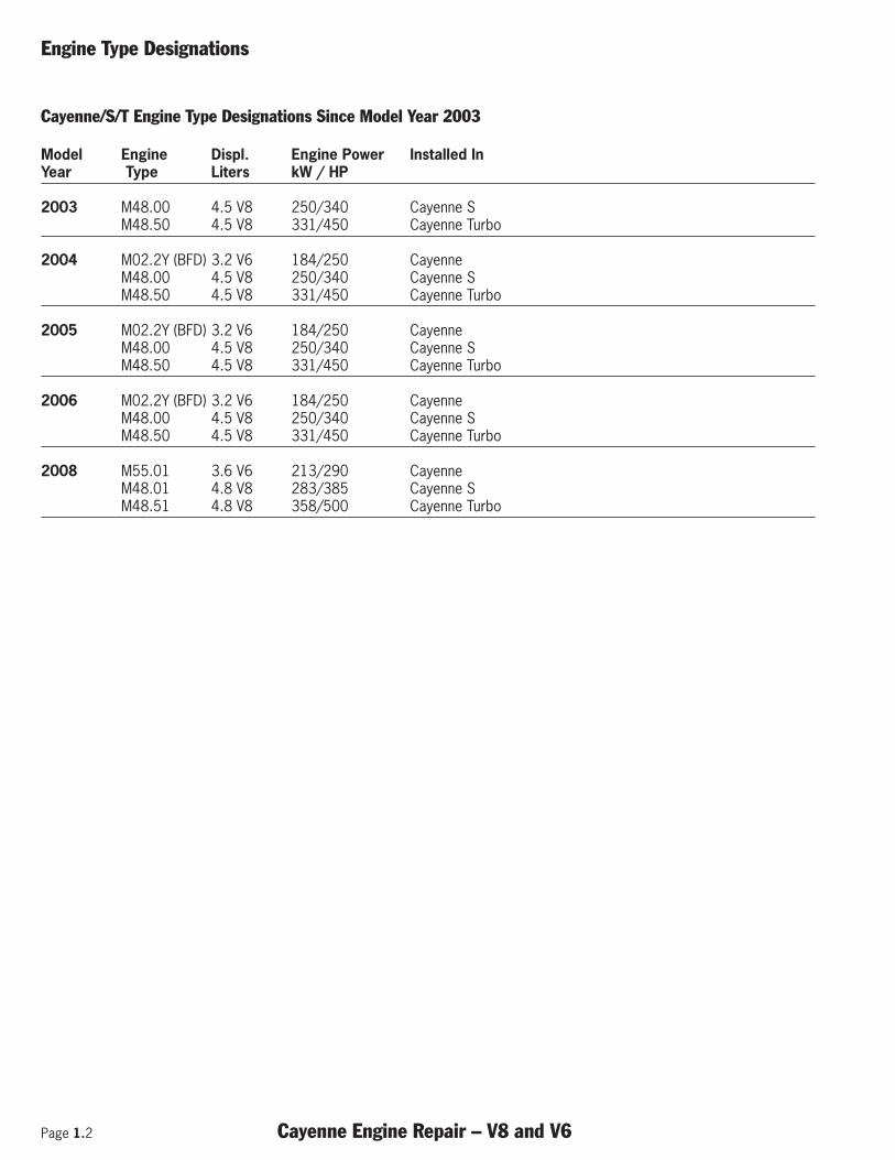
Engine Type Designations
Cayenne/S/T Engine Type Designations Since Model Year 2003
Model Engine Displ. Engine Power Installed InYear Type Liters kW / HP
2003 M48.00 4.5 V8 250/340 Cayenne SM48.50 4.5 V8 331/450 Cayenne Turbo
2004 M02.2Y (BFD) 3.2 V6 184/250 Cayenne M48.00 4.5 V8 250/340 Cayenne SM48.50 4.5 V8 331/450 Cayenne Turbo
2005 M02.2Y (BFD) 3.2 V6 184/250 Cayenne M48.00 4.5 V8 250/340 Cayenne SM48.50 4.5 V8 331/450 Cayenne Turbo
2006 M02.2Y (BFD) 3.2 V6 184/250 Cayenne M48.00 4.5 V8 250/340 Cayenne SM48.50 4.5 V8 331/450 Cayenne Turbo
2008 M55.01 3.6 V6 213/290 Cayenne M48.01 4.8 V8 283/385 Cayenne SM48.51 4.8 V8 358/500 Cayenne Turbo
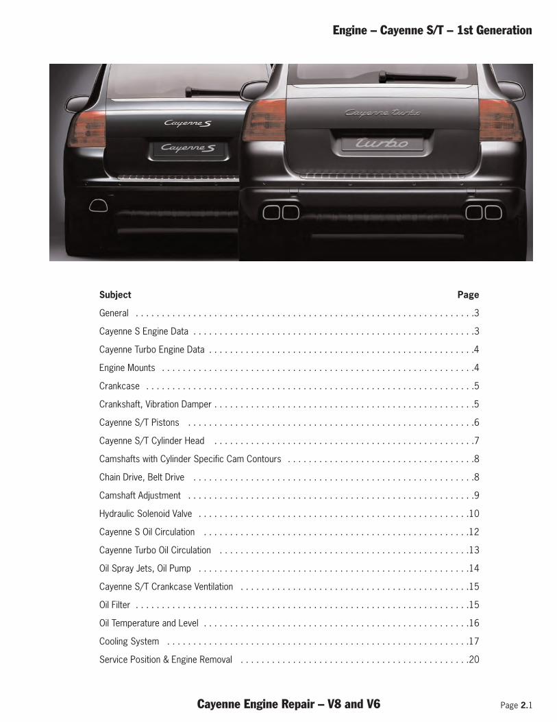
Engine – Cayenne S/T – 1st Generation
Cayenne Engine Repair – V8 and V6 Page 2.1
Subject Page
General . . . . . . . . . . . . . . . . . . . . . . . . . . . . . . . . . . . . . . . . . . . . . . . . . . . . . . . . . . . . . . . . .3
Cayenne S Engine Data . . . . . . . . . . . . . . . . . . . . . . . . . . . . . . . . . . . . . . . . . . . . . . . . . . . . . .3
Cayenne Turbo Engine Data . . . . . . . . . . . . . . . . . . . . . . . . . . . . . . . . . . . . . . . . . . . . . . . . . . .4
Engine Mounts . . . . . . . . . . . . . . . . . . . . . . . . . . . . . . . . . . . . . . . . . . . . . . . . . . . . . . . . . . . .4
Crankcase . . . . . . . . . . . . . . . . . . . . . . . . . . . . . . . . . . . . . . . . . . . . . . . . . . . . . . . . . . . . . . .5
Crankshaft, Vibration Damper . . . . . . . . . . . . . . . . . . . . . . . . . . . . . . . . . . . . . . . . . . . . . . . . . .5
Cayenne S/T Pistons . . . . . . . . . . . . . . . . . . . . . . . . . . . . . . . . . . . . . . . . . . . . . . . . . . . . . . .6
Cayenne S/T Cylinder Head . . . . . . . . . . . . . . . . . . . . . . . . . . . . . . . . . . . . . . . . . . . . . . . . . .7
Camshafts with Cylinder Specific Cam Contours . . . . . . . . . . . . . . . . . . . . . . . . . . . . . . . . . . . .8
Chain Drive, Belt Drive . . . . . . . . . . . . . . . . . . . . . . . . . . . . . . . . . . . . . . . . . . . . . . . . . . . . . .8
Camshaft Adjustment . . . . . . . . . . . . . . . . . . . . . . . . . . . . . . . . . . . . . . . . . . . . . . . . . . . . . . .9
Hydraulic Solenoid Valve . . . . . . . . . . . . . . . . . . . . . . . . . . . . . . . . . . . . . . . . . . . . . . . . . . . .10
Cayenne S Oil Circulation . . . . . . . . . . . . . . . . . . . . . . . . . . . . . . . . . . . . . . . . . . . . . . . . . . .12
Cayenne Turbo Oil Circulation . . . . . . . . . . . . . . . . . . . . . . . . . . . . . . . . . . . . . . . . . . . . . . . .13
Oil Spray Jets, Oil Pump . . . . . . . . . . . . . . . . . . . . . . . . . . . . . . . . . . . . . . . . . . . . . . . . . . . .14
Cayenne S/T Crankcase Ventilation . . . . . . . . . . . . . . . . . . . . . . . . . . . . . . . . . . . . . . . . . . . .15
Oil Filter . . . . . . . . . . . . . . . . . . . . . . . . . . . . . . . . . . . . . . . . . . . . . . . . . . . . . . . . . . . . . . . .15
Oil Temperature and Level . . . . . . . . . . . . . . . . . . . . . . . . . . . . . . . . . . . . . . . . . . . . . . . . . . .16
Cooling System . . . . . . . . . . . . . . . . . . . . . . . . . . . . . . . . . . . . . . . . . . . . . . . . . . . . . . . . . .17
Service Position & Engine Removal . . . . . . . . . . . . . . . . . . . . . . . . . . . . . . . . . . . . . . . . . . . .20
Page 2.2 Cayenne Engine Repair – V8 and V6
Engine – Cayenne S/T – 1st Generation
Notes:
Engine – Cayenne S/T – 1st Generation
Cayenne Engine Repair – V8 and V6 Page 2.3
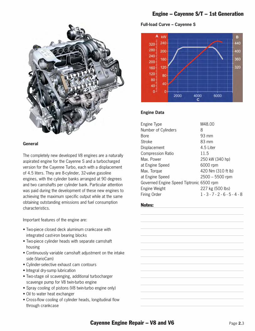
General
The completely new developed V8 engines are a naturallyaspirated engine for the Cayenne S and a turbochargedversion for the Cayenne Turbo, each with a displacementof 4.5 liters. They are 8-cylinder, 32-valve gasolineengines, with the cylinder banks arranged at 90 degreesand two camshafts per cylinder bank. Particular attentionwas paid during the development of these new engines toachieving the maximum specific output while at the sameobtaining outstanding emissions and fuel consumptioncharacteristics.
Important features of the engine are:
• Two-piece closed deck aluminum crankcase withintegrated cast-iron bearing blocks
• Two-piece cylinder heads with separate camshafthousing
• Continuously variable camshaft adjustment on the intakeside (VarioCam)
• Cylinder-selective exhaust cam contours • Integral dry-sump lubrication • Two-stage oil scavenging, additional turbocharger
scavenge pump for V8 twin-turbo engine • Spray cooling of pistons (V8 twin-turbo engine only) • Oil to water heat exchanger • Cross-flow cooling of cylinder heads, longitudinal flow
through crankcase
Full-load Curve – Cayenne S
Engine Data
Engine Type M48.00 Number of Cylinders 8Bore 93 mm Stroke 83 mm Displacement 4.5 LiterCompression Ratio 11.5 Max. Power 250 kW (340 hp) at Engine Speed 6000 rpm Max. Torque 420 Nm (310 ft lb) at Engine Speed 2500 – 5500 rpmGoverned Engine Speed Tiptronic 6500 rpm Engine Weight 227 kg (500 lbs)Firing Order 1 - 3 - 7 - 2 - 6 - 5 - 4 - 8
Notes:
Page 2.4 Cayenne Engine Repair – V8 and V6
Engine – Cayenne S/T – 1st Generation
Full-load Curve – Cayenne Turbo
Engine Data
Engine Type M48.50 Number of cylinders 8 Bore 93 mm Stroke 83 mm Displacement 4.5 Liter Compression Ratio 9.5 Max. Power 331 kW (450 hp) at Engine Speed 6000 rpm Max. Torque 620 Nm (458 ft lb) at Engine Speed 2250 - 4750 rpmGoverned Engine Speed Tiptronic 6500 rpm Engine Weight 253 kg (558 lbs)Firing Order 1 - 3 - 7 - 2 - 6 - 5 - 4 - 8
Notes:
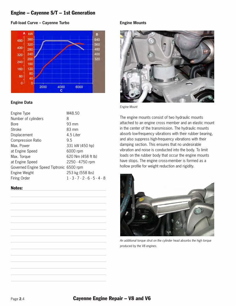
Engine Mounts
Engine Mount
The engine mounts consist of two hydraulic mountsattached to an engine cross member and an elastic mountin the center of the transmission. The hydraulic mountsabsorb low-frequency vibrations with their rubber bearing,and also suppress high-frequency vibrations with theirdamping section. This ensures that no undesirablevibration and noise is conducted into the body. To limitloads on the rubber body that occur the engine mountshave stops. The engine cross-member is formed as ahollow profile for weight reduction and rigidity.
An additional torque strut on the cylinder head absorbs the high torque
produced by the V8 engines.
Engine – Cayenne S/T – 1st Generation
Cayenne Engine Repair – V8 and V6 Page 2.5
Crankcase
Engine Components
The crankcase in the Porsche Cayenne is a two-piece“closed deck” design, made of a light-weight alloy(AlSi17Cu4Mg). In closed deck construction, the sealingsurface of the crankcase to the cylinder head is largelyclosed, only the bores and passages for oil and coolantare present. This design will strengthen the entirestructure. The result is less cylinder distortion and benefitsin oil consumption.
The alloy for the crankcase housing is a so-called hypereu-tectic alloy, in which silicon crystals are formed. To createa wear-resistant surface on the cylinder walls, these siliconcrystals are uncovered by multiple special honingprocedures. To minimize thermal changes in bearingclearance and thus reduce mechanical noise, the lowersection of the crankcase is furnished with cast-in cast ironbearing blocks. Another advantage is that when the engineis at operating temperature, oil flow at the main bearingsdoes not increase substantially as a result of the constantbearing clearance (approximately the same coefficient ofthermal expansion between steel/crankshaft and castiron/bearing block).
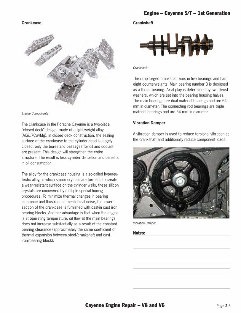
Crankshaft
Crankshaft
The drop-forged crankshaft runs in five bearings and haseight counterweights. Main bearing number 3 is designedas a thrust bearing. Axial play is determined by two thrustwashers, which are set into the bearing housing halves.The main bearings are dual material bearings and are 64mm in diameter. The connecting rod bearings are triplematerial bearings and are 54 mm in diameter.
Vibration Damper
A vibration damper is used to reduce torsional vibration atthe crankshaft and additionally reduce component loads.
Vibration Damper
Notes:
Page 2.6 Cayenne Engine Repair – V8 and V6
Engine – Cayenne S/T – 1st Generation
Connecting Rods
Connecting Rod
After machining, the forged connecting rods are brokenapart at the rod bearing (cracked). The two parts arecentered to one another by means of the resulting fracturepattern. To prevent incorrect assembly, the connectingrods are marked with additional matching pairs ofnumbers and the bores for the big-end bolts are offset.
Pistons
The pistons for the naturally aspirated engines are cast.
Cayenne S Piston
Cayenne S Piston Cross Section
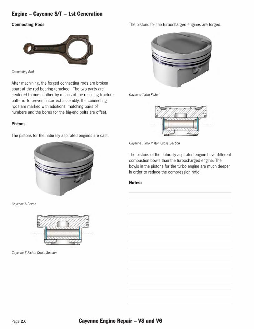
The pistons for the turbocharged engines are forged.
Cayenne Turbo Piston
Cayenne Turbo Piston Cross Section
The pistons of the naturally aspirated engine have differentcombustion bowls than the turbocharged engine. Thebowls in the pistons for the turbo engine are much deeperin order to reduce the compression ratio.
Notes:
Engine – Cayenne S/T – 1st Generation
Cayenne Engine Repair – V8 and V6 Page 2.7
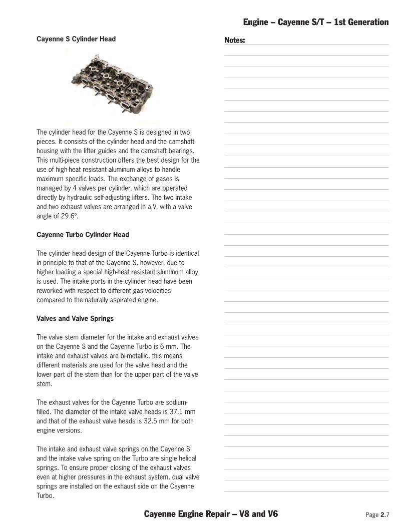
Cayenne S Cylinder Head
The cylinder head for the Cayenne S is designed in twopieces. It consists of the cylinder head and the camshafthousing with the lifter guides and the camshaft bearings.This multi-piece construction offers the best design for theuse of high-heat resistant aluminum alloys to handlemaximum specific loads. The exchange of gases ismanaged by 4 valves per cylinder, which are operateddirectly by hydraulic self-adjusting lifters. The two intakeand two exhaust valves are arranged in a V, with a valveangle of 29.6º.
Cayenne Turbo Cylinder Head
The cylinder head design of the Cayenne Turbo is identicalin principle to that of the Cayenne S, however, due tohigher loading a special high-heat resistant aluminum alloyis used. The intake ports in the cylinder head have beenreworked with respect to different gas velocitiescompared to the naturally aspirated engine.
Valves and Valve Springs
The valve stem diameter for the intake and exhaust valveson the Cayenne S and the Cayenne Turbo is 6 mm. Theintake and exhaust valves are bi-metallic, this meansdifferent materials are used for the valve head and thelower part of the stem than for the upper part of the valvestem.
The exhaust valves for the Cayenne Turbo are sodium-filled. The diameter of the intake valve heads is 37.1 mmand that of the exhaust valve heads is 32.5 mm for bothengine versions.
The intake and exhaust valve springs on the Cayenne Sand the intake valve spring on the Turbo are single helicalsprings. To ensure proper closing of the exhaust valveseven at higher pressures in the exhaust system, dual valvesprings are installed on the exhaust side on the CayenneTurbo.
Notes:
Page 2.8 Cayenne Engine Repair – V8 and V6
Engine – Cayenne S/T – 1st Generation
Camshafts with Cylinder Specific Cam Contours
The intake and exhaust camshafts for both engineversions have a base diameter of 38 mm. Intake valve liftis 10 mm. Exhaust valve lift for cylinders 1, 2, 6 and 8 is8 mm, for cylinders 3, 4, 5 and 7 exhaust valve lift is 9.85mm.
The engine design with a V8 crankshaft and 90º throwsensures outstanding balancing of masses and forces.However, with this engine design and a layout with conven-tional cam contours (equal cam lift) individual cylinderswould hamper each other as gas flows out into theexhaust manifold. The reason is that the exhaust leadimpulse of the particular cylinder on the exhaust stroke(e.g. cylinder number 2) gets into the crossover phase ofthe following cylinder (cylinder number 3). This would havea detrimental effect on cylinder filling. In addition, excessresidual gases have a negative effect on the knock limit.Because of the Cayenne's firing order (1 – 3 – 7 – 2 – 6 –5 – 4 – 8), cylinders 3 and 4 as well as 5 and 7 would beat a disadvantage in their charge. These cylinders aregiven higher cam lift. This step achieves equal filling of thecylinders, which results in an optimized torque curveacross the entire rpm range.
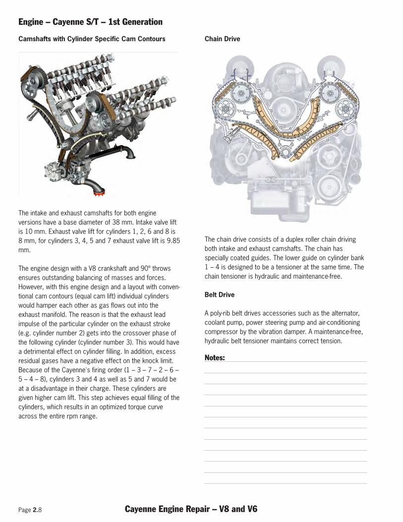
Chain Drive
The chain drive consists of a duplex roller chain drivingboth intake and exhaust camshafts. The chain hasspecially coated guides. The lower guide on cylinder bank1 – 4 is designed to be a tensioner at the same time. Thechain tensioner is hydraulic and maintenance-free.
Belt Drive
A poly-rib belt drives accessories such as the alternator,coolant pump, power steering pump and air-conditioningcompressor by the vibration damper. A maintenance-free,hydraulic belt tensioner maintains correct tension.
Notes:
Engine – Cayenne S/T – 1st Generation
Cayenne Engine Repair – V8 and V6 Page 2.9
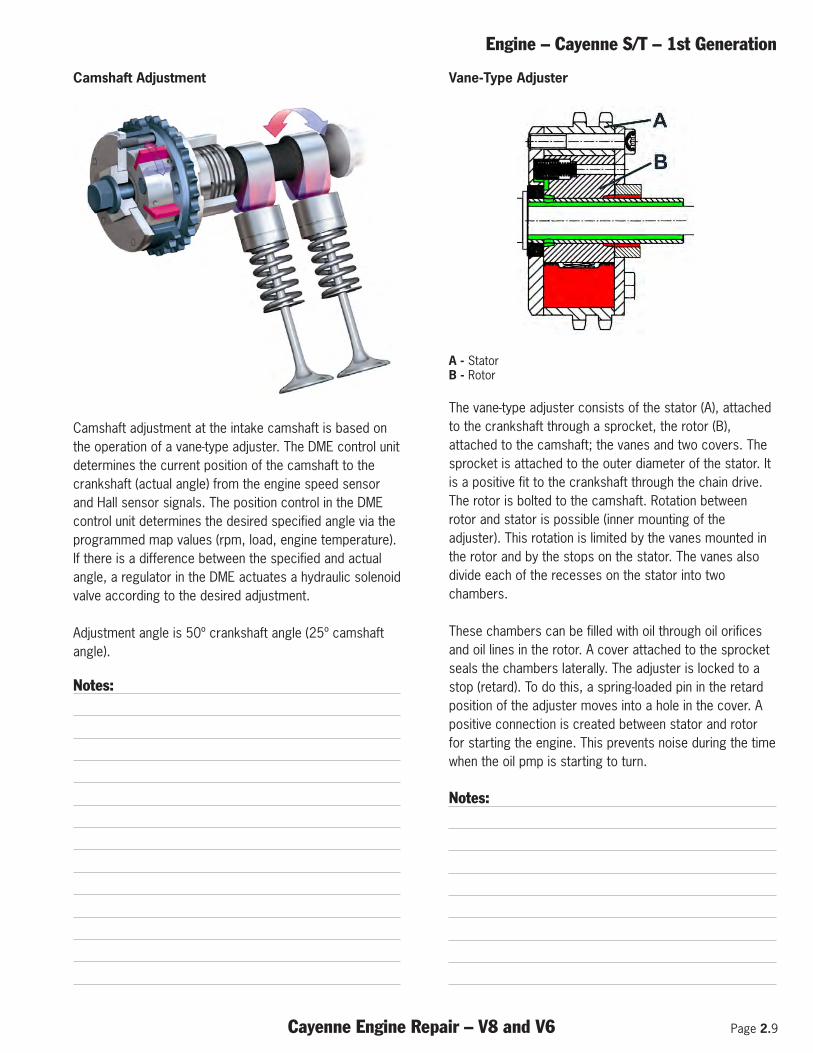
Camshaft Adjustment
Camshaft adjustment at the intake camshaft is based onthe operation of a vane-type adjuster. The DME control unitdetermines the current position of the camshaft to thecrankshaft (actual angle) from the engine speed sensorand Hall sensor signals. The position control in the DMEcontrol unit determines the desired specified angle via theprogrammed map values (rpm, load, engine temperature).If there is a difference between the specified and actualangle, a regulator in the DME actuates a hydraulic solenoidvalve according to the desired adjustment.
Adjustment angle is 50º crankshaft angle (25º camshaftangle).
Notes:
Vane-Type Adjuster
A - StatorB - Rotor
The vane-type adjuster consists of the stator (A), attachedto the crankshaft through a sprocket, the rotor (B),attached to the camshaft; the vanes and two covers. Thesprocket is attached to the outer diameter of the stator. Itis a positive fit to the crankshaft through the chain drive.The rotor is bolted to the camshaft. Rotation betweenrotor and stator is possible (inner mounting of theadjuster). This rotation is limited by the vanes mounted inthe rotor and by the stops on the stator. The vanes alsodivide each of the recesses on the stator into twochambers.
These chambers can be filled with oil through oil orificesand oil lines in the rotor. A cover attached to the sprocketseals the chambers laterally. The adjuster is locked to astop (retard). To do this, a spring-loaded pin in the retardposition of the adjuster moves into a hole in the cover. Apositive connection is created between stator and rotorfor starting the engine. This prevents noise during the timewhen the oil pmp is starting to turn.
Notes:
`~ãëÜ~Ñí=^ÇàìëíãÉåí=`~óÉååÉ=
1_26_03
Camshaft adjustment at the intake camshaft is based on the principle of a
vane-type adjuster. The DME control module determines the current
position of the camshaft to the crankshaft (actual angle) from the engine
speed sensor and Hall sensor signals. The position control in the control
module receives the desired specified angle via the programmed map
values (rpm, load, engine temperature). If there is a difference between
the specified and actual angle, a regulator in the DME control module
actuates a hydraulic solenoid valve according to the desired adjustment.
Adjustment angle is 50º crankshaft angle (25º camshaft angle).
1.12/ 2003
Page 2.10 Cayenne Engine Repair – V8 and V6
Engine – Cayenne S/T – 1st Generation
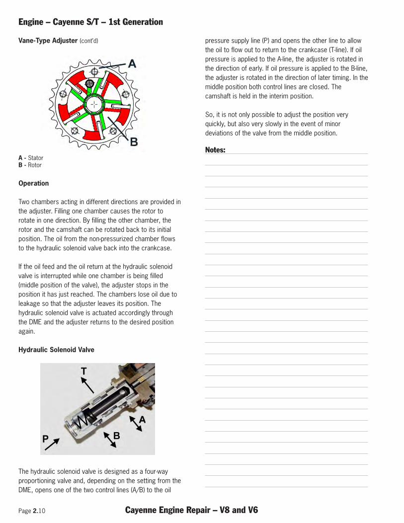
Vane-Type Adjuster (cont’d)
A - StatorB - Rotor
Operation
Two chambers acting in different directions are provided inthe adjuster. Filling one chamber causes the rotor torotate in one direction. By filling the other chamber, therotor and the camshaft can be rotated back to its initialposition. The oil from the non-pressurized chamber flowsto the hydraulic solenoid valve back into the crankcase.
If the oil feed and the oil return at the hydraulic solenoidvalve is interrupted while one chamber is being filled(middle position of the valve), the adjuster stops in theposition it has just reached. The chambers lose oil due toleakage so that the adjuster leaves its position. Thehydraulic solenoid valve is actuated accordingly throughthe DME and the adjuster returns to the desired positionagain.
Hydraulic Solenoid Valve
The hydraulic solenoid valve is designed as a four-wayproportioning valve and, depending on the setting from theDME, opens one of the two control lines (A/B) to the oil
pressure supply line (P) and opens the other line to allowthe oil to flow out to return to the crankcase (T-line). If oilpressure is applied to the A-line, the adjuster is rotated inthe direction of early. If oil pressure is applied to the B-line,the adjuster is rotated in the direction of later timing. In themiddle position both control lines are closed. Thecamshaft is held in the interim position.
So, it is not only possible to adjust the position veryquickly, but also very slowly in the event of minordeviations of the valve from the middle position.
Notes:
eóÇê~ìäáÅ=pçäÉåçáÇ=s~äîÉ=`~óÉååÉ=
1_07_02
The hydraulic solenoid valve is designed as a four-way proportioning valve
and, depending on the setting from the control module, connects one of
the two control lines (A/B) to the oil pressure supply line (P) and opens
the other line to allow the oil to flow out into the crankcase (T-line). If oil
pressure is applied to the A-line, the adjuster is rotated in the direction of
early. If oil pressure is applied to the B-line, the adjuster is rotated in the
direction of later timing. In the middle position both control lines are
closed. The camshaft is held in the desired position. Any interim position
between the three positions described can be set through the control
module.
So it is not only possible to adjust the position very quickly, but also very
slowly in the event of minor deviations of the valve from the middle
position. The hydraulic solenoid valve sets the direction and the speed of
adjustment of the adjuster.
1.14/ 2003
s~åÉJqóéÉ=^ÇàìëíÉê= `~óÉååÉ
The vane-type adjuster consists of the stator (A) – attached to the
crankshaft through a sprocket –, the rotor (B) – attached to the camshaft
– the vanes and two covers. The sprocket is attached to the outer
diameter of the stator. It is a positive fit to the crankshaft through the
chain drive. The rotor is bolted to the camshaft. Rotation between rotor
and stator is possible (inner mounting of the adjuster). This rotation is
limited by the vanes mounted in the rotor and by the stops on the stator.
The vanes also divide each of the recesses on the stator into two
chambers.
1_03_02
These chambers can be filled with oil via oil orifices and oil lines in the
rotor.
A cover attached to the sprocket seals the chambers laterally. The
adjuster is locked to a stop (retard). To do this, a spring-loaded pin in the
retard position of the adjuster moves into a hole in the cover. A positive
connection is created between stator and rotor for starting the engine.
Noise during the period of no oil pressure is prevented by means of this
locking action.A – Stator
B – Rotor
Operation
Two chambers acting in different directions are provided in the adjuster.
Filling one chamber causes the rotor to rotate with respect to the stator.
By filling the other chamber, the rotor and thus the camshaft can be
rotated back to its initial position. The oil from the non-pressurized
chamber flows via the hydraulic solenoid valve back into the crankcase. If
the oil feed and the oil return at the hydraulic solenoid valve is interrupted
while one chamber is being filled (middle position of the valve), the
adjuster stops in the position it has just assumed. The chambers lose oil
due to leakage so that the adjuster leaves its position. The hydraulic
solenoid valve is actuated accordingly through the control module, and
the adjuster returns to the desired position again.
1_03a_02
1.13 / 2003
Engine – Cayenne S/T – 1st Generation
Cayenne Engine Repair – V8 and V6 Page 2.11
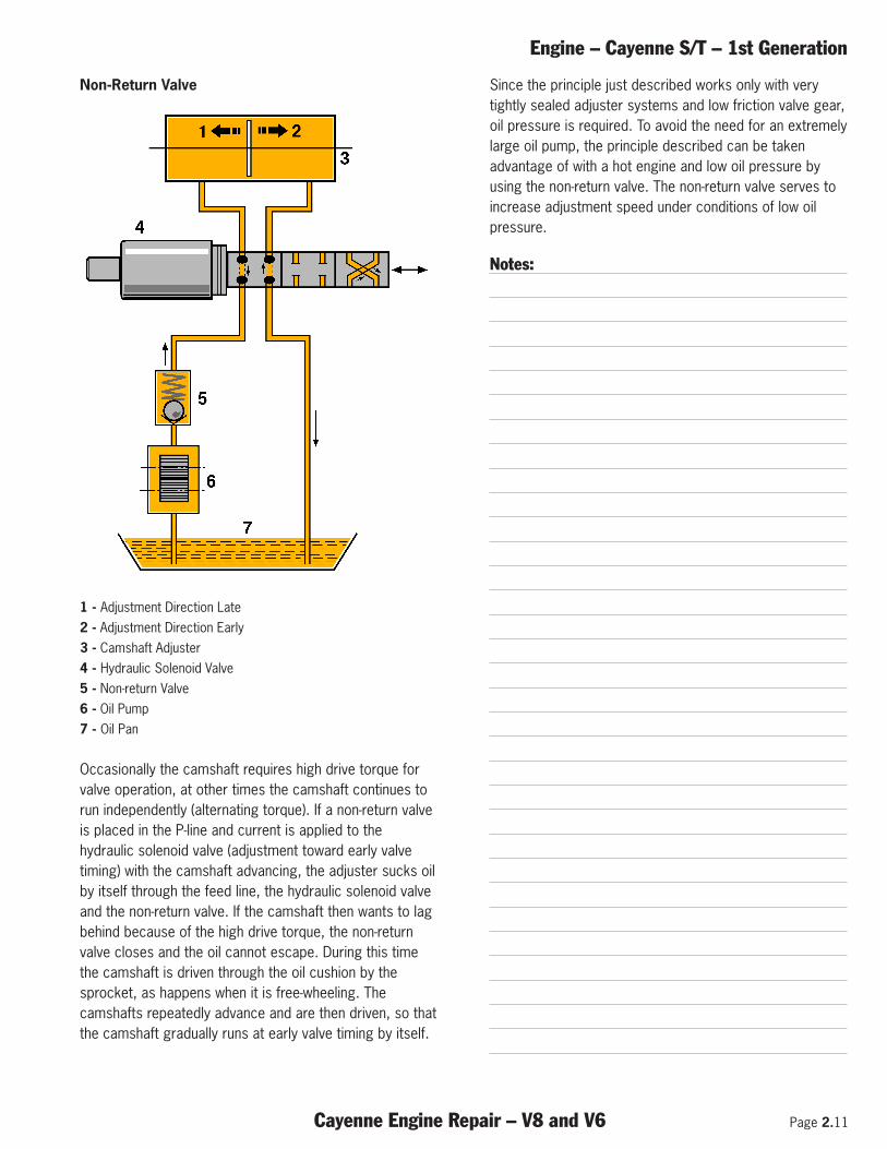
Non-Return Valve
1 - Adjustment Direction Late 2 - Adjustment Direction Early 3 - Camshaft Adjuster 4 - Hydraulic Solenoid Valve 5 - Non-return Valve 6 - Oil Pump 7 - Oil Pan
Occasionally the camshaft requires high drive torque forvalve operation, at other times the camshaft continues torun independently (alternating torque). If a non-return valveis placed in the P-line and current is applied to thehydraulic solenoid valve (adjustment toward early valvetiming) with the camshaft advancing, the adjuster sucks oilby itself through the feed line, the hydraulic solenoid valveand the non-return valve. If the camshaft then wants to lagbehind because of the high drive torque, the non-returnvalve closes and the oil cannot escape. During this timethe camshaft is driven through the oil cushion by thesprocket, as happens when it is free-wheeling. Thecamshafts repeatedly advance and are then driven, so thatthe camshaft gradually runs at early valve timing by itself.
Since the principle just described works only with verytightly sealed adjuster systems and low friction valve gear,oil pressure is required. To avoid the need for an extremelylarge oil pump, the principle described can be takenadvantage of with a hot engine and low oil pressure byusing the non-return valve. The non-return valve serves toincrease adjustment speed under conditions of low oilpressure.
Notes:
kçåJoÉíìêå=s~äîÉ= `~óÉååÉ
1 – Adjustment Direction Late
2 – Adjustment Direction Early
3 – Camshaft Adjuster
4 – Hydraulic Solenoid Valve
5 – Non-return Valve
6 – Oil Pump
7 – Oil Pan
1_01_03
Occasionally the camshaft requires high drive torque for valve operation,
at other times the camshaft continues to run independently (alternating
torque). If a non-return valve is placed in the P-line and current is applied
to the hydraulic solenoid valve (adjustment toward early valve timing) with
the camshaft advancing, the adjuster sucks oil by itself through the feed
line, the hydraulic solenoid valve and the non-return valve. If the
camshaft then wants to lag behind because of the high drive torque, the
non-return valve closes and the oil cannot escape. During this time the
camshaft is driven through the oil cushion by the sprocket, as happens
when it is free-wheeling. The camshafts repeatedly advance and are then
driven, so that the camshaft gradually runs at early valve timing by itself.
Since the principle just described works only with very tightly sealed
adjuster systems and low friction valve gear, oil pressure is required. To
avoid the need for an extremely large oil pump, the principle described
can be taken advantage of with a hot engine and low oil pressure by using
the non-return valve. The non-return valve serves to increase adjustment
speed under conditions of low oil pressure.
1.15 / 2003
Page 2.12 Cayenne Engine Repair – V8 and V6
Engine – Cayenne S/T – 1st Generation
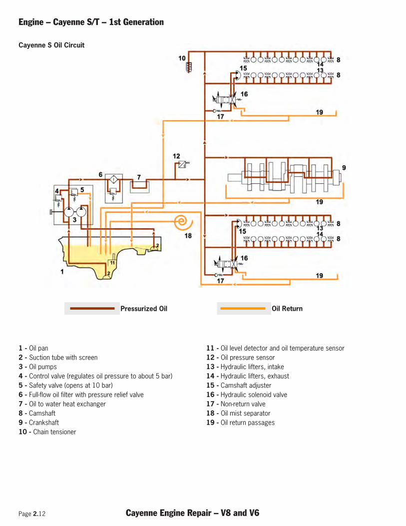
1 - Oil pan2 - Suction tube with screen 3 - Oil pumps 4 - Control valve (regulates oil pressure to about 5 bar) 5 - Safety valve (opens at 10 bar) 6 - Full-flow oil filter with pressure relief valve 7 - Oil to water heat exchanger 8 - Camshaft 9 - Crankshaft 10 - Chain tensioner
11 - Oil level detector and oil temperature sensor 12 - Oil pressure sensor 13 - Hydraulic lifters, intake 14 - Hydraulic lifters, exhaust15 - Camshaft adjuster 16 - Hydraulic solenoid valve 17 - Non-return valve 18 - Oil mist separator 19 - Oil return passages
`~óÉååÉ=p=láä=`áêÅìä~íáçå=`~óÉååÉ=
Pressurized oil Oil return
1_13_03
1 – Oil
2 – Suction tube with screen
3 – Oil pump
4 – Control valve (regulates oil
pressure to about 5 bar)
5 – Safety valve (opens at 10 bar)
6 – Full-flow oil filter with pressure
relief valve
7 – Oil-water heat exchanger
8 – Camshaft
9 – Crankshaft
10 – Chain tensioner
11 – Oil level detector and oil
temperature sensor
12 – Oil pressure sensor
13 – Hydraulic lifters inlet
14 – Hydraulic lifters outlet
15 – Camshaft adjuster
16 – Hydraulic solenoid valve
17 – Non-return valve
18 – Oil mist separator
19 – Oil return passages
1.16/ 2003
Cayenne S Oil Circuit
Pressurized Oil Oil Return
Engine – Cayenne S/T – 1st Generation
Cayenne Engine Repair – V8 and V6 Page 2.13
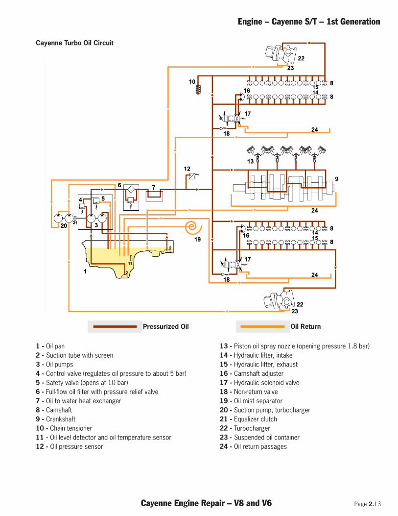
1 - Oil pan 2 - Suction tube with screen 3 - Oil pumps 4 - Control valve (regulates oil pressure to about 5 bar) 5 - Safety valve (opens at 10 bar) 6 - Full-flow oil filter with pressure relief valve 7 - Oil to water heat exchanger 8 - Camshaft 9 - Crankshaft 10 - Chain tensioner 11 - Oil level detector and oil temperature sensor 12 - Oil pressure sensor
13 - Piston oil spray nozzle (opening pressure 1.8 bar) 14 - Hydraulic lifter, intake15 - Hydraulic lifter, exhaust 16 - Camshaft adjuster 17 - Hydraulic solenoid valve 18 - Non-return valve 19 - Oil mist separator 20 - Suction pump, turbocharger 21 - Equalizer clutch 22 - Turbocharger 23 - Suspended oil container 24 - Oil return passages
`~óÉååÉ=qìêÄç=láä=`áêÅìä~íáçå= `~óÉååÉ
Pressurized oil Oil return
1_14_03
13 – Piston oil spray nozzle
(opening pressure 1.8 bar)
14 – Hydraulic lifter inlet
15 – Hydraulic lifter outlet
16 – Camshaft adjuster
17 – Hydraulic solenoid valve
18 – Non-return valve
19 – Oil mist separator
20 – Suction pump turbocharger
21 – Equalizer clutch
22 – Turbocharger
23 – Suspended oil container
24 – Oil return passages
1 – Oil pan
2 – Suction tube with screen
3 – Oil pump
4 – Control valve (regulates oil pressure to about 5 bar)
5 – Safety valve (opens at 10 bar)
6 – Full-flow oil filter with pressure relief valve
7 – Oil-water heat exchanger
8 – Camshaft
9 – Crankshaft
10 – Chain tensioner
11 – Oil level detector and oil temperature sensor
12 – Oil pressure sensor
1.17 / 2003
`~óÉååÉ=p=láä=`áêÅìä~íáçå=`~óÉååÉ=
Pressurized oil Oil return
1_13_03
1 – Oil
2 – Suction tube with screen
3 – Oil pump
4 – Control valve (regulates oil
pressure to about 5 bar)
5 – Safety valve (opens at 10 bar)
6 – Full-flow oil filter with pressure
relief valve
7 – Oil-water heat exchanger
8 – Camshaft
9 – Crankshaft
10 – Chain tensioner
11 – Oil level detector and oil
temperature sensor
12 – Oil pressure sensor
13 – Hydraulic lifters inlet
14 – Hydraulic lifters outlet
15 – Camshaft adjuster
16 – Hydraulic solenoid valve
17 – Non-return valve
18 – Oil mist separator
19 – Oil return passages
1.16/ 2003
Cayenne Turbo Oil Circuit
Pressurized Oil Oil Return
Page 2.14 Cayenne Engine Repair – V8 and V6
Engine – Cayenne S/T – 1st Generation
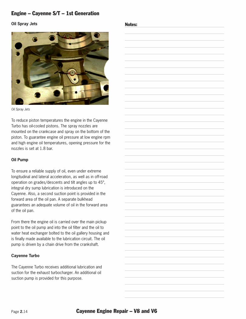
Oil Spray Jets
Oil Spray Jets
To reduce piston temperatures the engine in the CayenneTurbo has oil-cooled pistons. The spray nozzles aremounted on the crankcase and spray on the bottom of thepiston. To guarantee engine oil pressure at low engine rpmand high engine oil temperatures, opening pressure for thenozzles is set at 1.8 bar.
Oil Pump
To ensure a reliable supply of oil, even under extremelongitudinal and lateral acceleration, as well as in off-roadoperation on grades/descents and tilt angles up to 45º,integral dry sump lubrication is introduced on theCayenne. Also, a second suction point is provided in theforward area of the oil pan. A separate bulkheadguarantees an adequate volume of oil in the forward areaof the oil pan.
From there the engine oil is carried over the main pickuppoint to the oil pump and into the oil filter and the oil towater heat exchanger bolted to the oil gallery housing andis finally made available to the lubrication circuit. The oilpump is driven by a chain drive from the crankshaft.
Cayenne Turbo
The Cayenne Turbo receives additional lubrication andsuction for the exhaust turbocharger. An additional oilsuction pump is provided for this purpose.
Notes:láä=péê~ó=gÉíë=`~óÉååÉ=
1_24_03
To reduce piston temperatures the engine in the Cayenne Turbo has oil-
cooled pistons. The spray nozzles are mounted on the crankcase.
To guarantee engine oil pressure at low engine rpm and high engine oil
temperatures, opening pressure for the nozzles is set at 1.8 bar.
láä=mìãé=
To ensure a reliable supply of oil, even under extreme longitudinal and
lateral acceleration, as well as in off-road operation on grades/descents
and tilt angles up to 45º, integral dry sump lubrication is introduced on
the Cayenne. In addition, a second suction point is provided in the
forward area of the oil pan. A separate bulkhead guarantees an adequate
volume of oil in the forward area of the oil pan. From there the engine oil
is carried over the main pickup point through the oil pump into the oil
filter and the oil-water heat exchanger bolted to the oil gallery housing
and is finally made available to the lubrication circuit.
The oil pump is driven by a chain drive from the crankshaft.
`~óÉååÉ=qìêÄç
The Cayenne Turbo receives additional lubrication and suction for the
exhaust turbocharger. An additional oil suction pump is provided for this
purpose.
1.18/ 2003
Engine – Cayenne S/T – 1st Generation
Cayenne Engine Repair – V8 and V6 Page 2.15
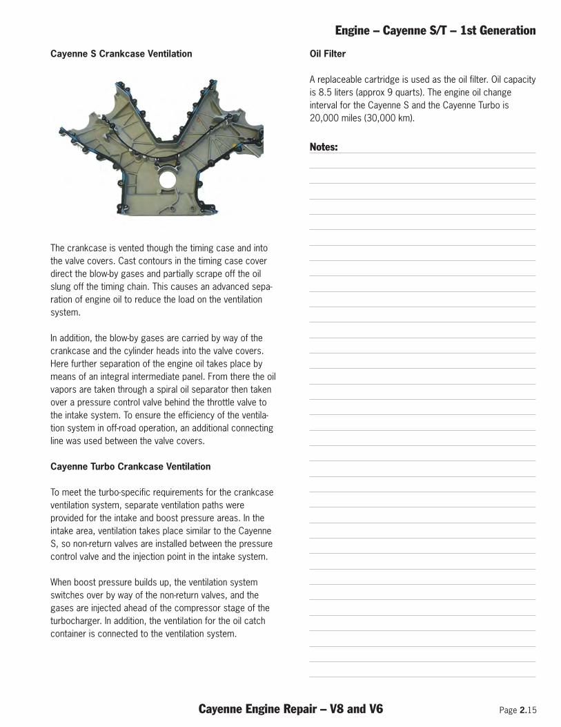
Cayenne S Crankcase Ventilation
The crankcase is vented though the timing case and intothe valve covers. Cast contours in the timing case coverdirect the blow-by gases and partially scrape off the oilslung off the timing chain. This causes an advanced sepa-ration of engine oil to reduce the load on the ventilationsystem.
In addition, the blow-by gases are carried by way of thecrankcase and the cylinder heads into the valve covers.Here further separation of the engine oil takes place bymeans of an integral intermediate panel. From there the oilvapors are taken through a spiral oil separator then takenover a pressure control valve behind the throttle valve tothe intake system. To ensure the efficiency of the ventila-tion system in off-road operation, an additional connectingline was used between the valve covers.
Cayenne Turbo Crankcase Ventilation
To meet the turbo-specific requirements for the crankcaseventilation system, separate ventilation paths wereprovided for the intake and boost pressure areas. In theintake area, ventilation takes place similar to the CayenneS, so non-return valves are installed between the pressurecontrol valve and the injection point in the intake system.
When boost pressure builds up, the ventilation systemswitches over by way of the non-return valves, and thegases are injected ahead of the compressor stage of theturbocharger. In addition, the ventilation for the oil catchcontainer is connected to the ventilation system.
Oil Filter
A replaceable cartridge is used as the oil filter. Oil capacityis 8.5 liters (approx 9 quarts). The engine oil changeinterval for the Cayenne S and the Cayenne Turbo is20,000 miles (30,000 km).
Notes:
`~óÉååÉ=p=`ê~åâÅ~ëÉ=sÉåíáä~íáçå= `~óÉååÉ
Crankcase ventilation takes place over the timing case into the valve
covers. Suitable cast contours are provided in the time case cover, which
partially scrape off the oil entrained by the timing chain.
This achieves a type of advance separation of the engine oil to reduce the
load on the ventilation system.
In addition, the blow-by gases are carried by way of the crankcase and the
cylinder heads into the valve covers. Here further advance separation of
the engine oil takes place by means of an integral intermediate panel.
From there the oil vapors are taken through a spiral oil separator, freed
from the very smallest oil particles and then taken over a pressure control
valve behind the throttle valve to the induction system. To ensure the
efficiency of the ventilation system in off-road operation, an additional
connecting line was used between the valve covers.
`~óÉååÉ=qìêÄç=`ê~åâÅ~ëÉ=sÉåíáä~íáçå=
To meet the turbo-specific requirements for the crankcase ventilation
system, separate ventilation paths were provided for the intake and boost
pressure areas.
In the intake area ventilation takes place similar to the Cayenne S, so non-
return valves are installed between the pressure control valve and the
injection point in the induction system. When boost pressure builds up,
the ventilation system switches over by way of the non-return valves, and
the gases are injected ahead of the compressor stage of the turbocharger.
In addition, the ventilation for the oil catch container is connected to the
ventilation system.
NTPM= láä=cáäíÉê=
A replaceable cartridge is used as the oil filter.
Oil capacity is 8.5 liters (approx 9 quarts).
The engine oil change interval for the Cayenne S and the Cayenne Turbo
is 30,000 km.
1.19 / 2003
Page 2.16 Cayenne Engine Repair – V8 and V6
Engine – Cayenne S/T – 1st Generation
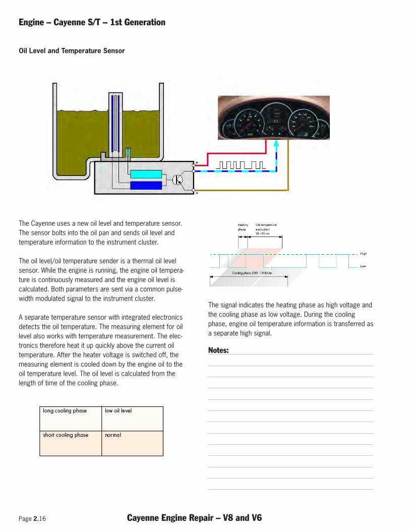
The Cayenne uses a new oil level and temperature sensor.The sensor bolts into the oil pan and sends oil level andtemperature information to the instrument cluster.
The oil level/oil temperature sender is a thermal oil levelsensor. While the engine is running, the engine oil tempera-ture is continuously measured and the engine oil level iscalculated. Both parameters are sent via a common pulse-width modulated signal to the instrument cluster.
A separate temperature sensor with integrated electronicsdetects the oil temperature. The measuring element for oillevel also works with temperature measurement. The elec-tronics therefore heat it up quickly above the current oiltemperature. After the heater voltage is switched off, themeasuring element is cooled down by the engine oil to theoil temperature level. The oil level is calculated from thelength of time of the cooling phase.
The signal indicates the heating phase as high voltage andthe cooling phase as low voltage. During the coolingphase, engine oil temperature information is transferred asa separate high signal.
Notes:
`~óÉååÉ=láä=iÉîÉä=~åÇ=qÉãéÉê~íìêÉ=pÉåëçê=
The Cayenne uses a new oil level and temperature sensor. The sensor
bolts into the oil pan and send oil level and temperature to the instrument
cluster.
The oil level/oil temperature sender is a thermal oil level sensor. While
the engine is running, the engine oil temperature is continuously
measured and the engine oil level is calculated. Both parameters are sent
via a common pulse-width modulated signal to the instrument cluster.
A separate temperature sensor with integrated electronics detects the oil
temperature. The measuring element for oil level also works with
temperature measurement. The electronics therefore heat it up quickly
above the current oil temperature.
After the heater voltage is switched off, the measuring element is cooled
down by the engine oil to the oil temperature level. The oil level is
calculated from the length of time of the cooling phase.
The signal indicates the heating phase as high voltage and the cooling
phase as low voltage.
During the cooling phase, engine oil temperature information is
transferred as a separate high signal.
1.20/ 2003
Oil Level and Temperature Sensor
Engine – Cayenne S/T – 1st Generation
Cayenne Engine Repair – V8 and V6 Page 2.17
Cooling System
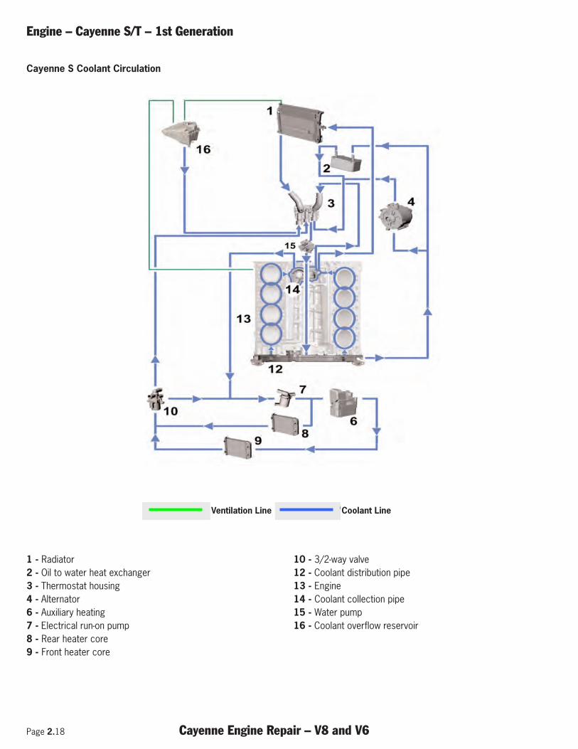
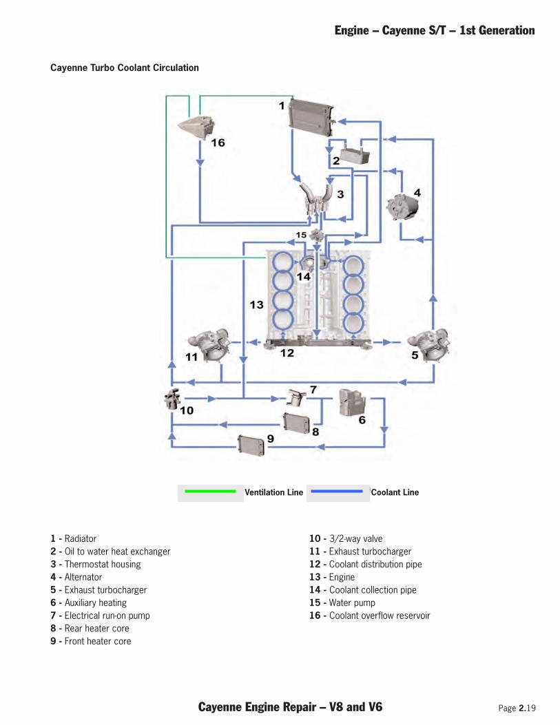
Coolant is circulated by the water pump (15) through aplastic pipe located in the internal V of the engine to thedistribution pipe (12) on the transmission side of theengine. The coolant flow is separated in the distributionpipe, about 20% of the coolant is fed into the water jacketof the crankcase and passes through it in the longitudinaldirection. About 80% of the coolant volume is fed into thecylinder heads on the cross-flow principle to achieveoptimal temperature distribution and passes through themfrom the hotter (outlet) to the cooler side.
Ahead of the thermostat housing (3) the coolant flows arebrought together again, and, with the thermostat closed(reduced circulation), taken directly to the water pumpagain.
The thermostat starts to open at 181° F (83° C), lift is 9.8mm at 208° F (98° C), and it reaches its maximumopening at 221 F (105° C). Coolant temperature ismeasured at the engine block inlet. With the thermostatopen (full circulation), the coolant is brought by way of theradiator at the front of the vehicle back to the intake sideof the water pump.
Heat from the engine oil is given off (2) into the coolant bymeans of an oil to water heat exchanger. Partial volumeflow for this and the liquid-cooled alternator (4) arediverted at the distribution pipe. Volume flow for heatercore is taken off at the thermostat housing. The return forboth flows is into the thermostat housing.
A supplementary electrical run-on pump (7) provides circu-lation in the coolant circuit even after the engine has beenswitched off. Depending on coolant temperature and thelast driving cycle (map derived from fuel consumption) thispump is actuated by the DME control unit through a relay.
On the Cayenne Turbo the two turbochargers (5 and 11)additionally have coolant directed around them. Thisgreatly reduces oil coking in the turbine bearing housing.
Notes:
Page 2.18 Cayenne Engine Repair – V8 and V6
Engine – Cayenne S/T – 1st Generation
1 - Radiator2 - Oil to water heat exchanger 3 - Thermostat housing 4 - Alternator 6 - Auxiliary heating 7 - Electrical run-on pump 8 - Rear heater core9 - Front heater core
10 - 3/2-way valve 12 - Coolant distribution pipe 13 - Engine 14 - Coolant collection pipe 15 - Water pump 16 - Coolant overflow reservoir
Cayenne S Coolant Circulation
`~óÉååÉ= `~óÉååÉ=p=`ççä~åí=`áêÅìä~íáçå=
Ventilation line Coolant line
1_20_03
1 – Radiator 9 – Heat exchanger for front heater
10 – 3/2-way valve
12 – Coolant distribution pipe
13 – Engine
14 – Coolant collection pipe
15 – Water pump
16 – Coolant overflow reservoir
2 – Oil-water heat exchanger
3 – Thermostat housing
4 – Alternator
6 – Auxiliary heating
7 – Electrical run-on pump
8 – Heat exchanger for rear heater
1.22/ 2003
Ventilation Line Coolant Line
Engine – Cayenne S/T – 1st Generation
Cayenne Engine Repair – V8 and V6 Page 2.19
1 - Radiator 2 - Oil to water heat exchanger 3 - Thermostat housing 4 - Alternator 5 - Exhaust turbocharger 6 - Auxiliary heating 7 - Electrical run-on pump 8 - Rear heater core9 - Front heater core
10 - 3/2-way valve 11 - Exhaust turbocharger 12 - Coolant distribution pipe 13 - Engine 14 - Coolant collection pipe 15 - Water pump 16 - Coolant overflow reservoir
Cayenne Turbo Coolant Circulation
`~óÉååÉ= `~óÉååÉ=p=`ççä~åí=`áêÅìä~íáçå=
Ventilation line Coolant line
1_20_03
1 – Radiator 9 – Heat exchanger for front heater
10 – 3/2-way valve
12 – Coolant distribution pipe
13 – Engine
14 – Coolant collection pipe
15 – Water pump
16 – Coolant overflow reservoir
2 – Oil-water heat exchanger
3 – Thermostat housing
4 – Alternator
6 – Auxiliary heating
7 – Electrical run-on pump
8 – Heat exchanger for rear heater
1.22/ 2003
Ventilation Line Coolant Line
Page 2.20 Cayenne Engine Repair – V8 and V6
Engine – Cayenne S/T – 1st Generation
Service Position
The Cayenne has an added feature of allowing the frontend to be moved forward into a service position formaintance and repair. The service position can beachieved without draining the fluids or air conditioningsystem refrigerant.
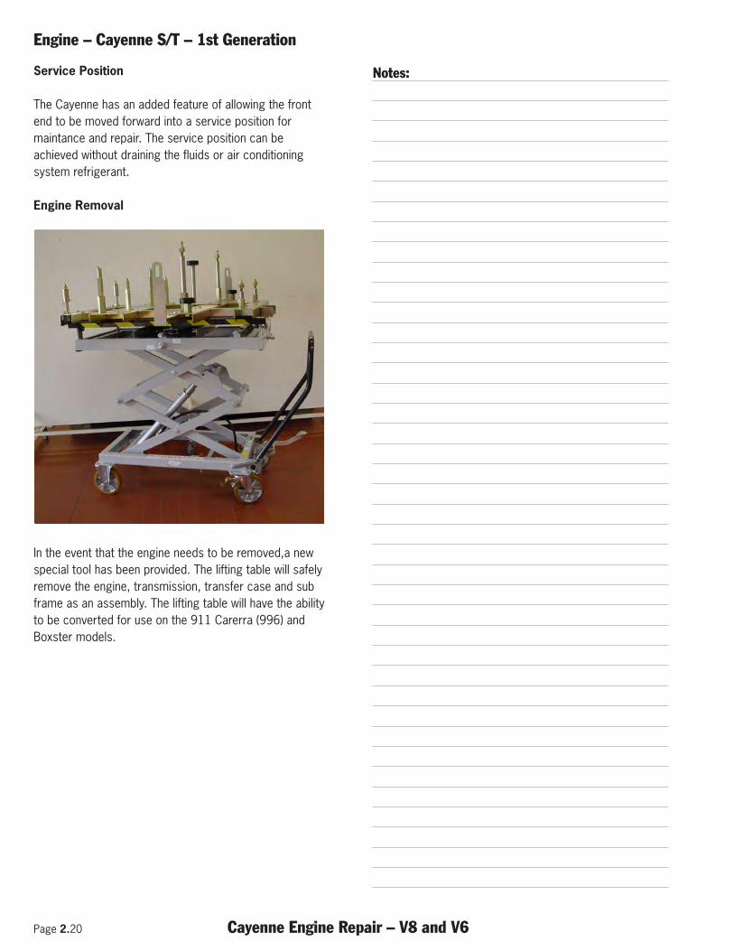
Engine Removal
In the event that the engine needs to be removed,a newspecial tool has been provided. The lifting table will safelyremove the engine, transmission, transfer case and subframe as an assembly. The lifting table will have the abilityto be converted for use on the 911 Carerra (996) andBoxster models.
Notes:
`~óÉååÉ=
1.24/ 2003
pÉêîáÅÉ mçëáíáçå
The Cayenne has an added feature of allowing the front end to be moved
forward into a service position for maintance and repair. The service
position can be achieved without draining the fluids or air conditioning
system refrigerant.
båÖáåÉ oÉãçî~ä
In the event that the engine is to removed a new special tool has be
provided. The lifting table will safely remove the engine, transmission,
transfer case and sub frame as an assembly.
The lifting table will have the ability to be retrofit for use on the 996 and
Boxster models.
Engine – Cayenne (V6) – 1st Generation
Cayenne Engine Repair – V8 and V6 Page 3.1
Subject Page
General . . . . . . . . . . . . . . . . . . . . . . . . . . . . . . . . . . . . . . . . . . . . . . . . . . . . . . . . . . . . . . . . .3
Cayenne Engine Data . . . . . . . . . . . . . . . . . . . . . . . . . . . . . . . . . . . . . . . . . . . . . . . . . . . . . . .3
Crankcase, Crankshaft . . . . . . . . . . . . . . . . . . . . . . . . . . . . . . . . . . . . . . . . . . . . . . . . . . . . . .4
Vibration Damper . . . . . . . . . . . . . . . . . . . . . . . . . . . . . . . . . . . . . . . . . . . . . . . . . . . . . . . . . . .5
Connecting Rods and Pistons . . . . . . . . . . . . . . . . . . . . . . . . . . . . . . . . . . . . . . . . . . . . . . . . . .5
Cylinder Head . . . . . . . . . . . . . . . . . . . . . . . . . . . . . . . . . . . . . . . . . . . . . . . . . . . . . . . . . . . . .5
Cylinder Head Gasket . . . . . . . . . . . . . . . . . . . . . . . . . . . . . . . . . . . . . . . . . . . . . . . . . . . . . . . .6
Timing With Variable Camshaft Control . . . . . . . . . . . . . . . . . . . . . . . . . . . . . . . . . . . . . . . . . . .6
Camshafts . . . . . . . . . . . . . . . . . . . . . . . . . . . . . . . . . . . . . . . . . . . . . . . . . . . . . . . . . . . . . . . .7
Belt Drive . . . . . . . . . . . . . . . . . . . . . . . . . . . . . . . . . . . . . . . . . . . . . . . . . . . . . . . . . . . . . . .10
Belt Tensioner . . . . . . . . . . . . . . . . . . . . . . . . . . . . . . . . . . . . . . . . . . . . . . . . . . . . . . . . . . . .10
Oil Lubrication System . . . . . . . . . . . . . . . . . . . . . . . . . . . . . . . . . . . . . . . . . . . . . . . . . . . . . .11
Oil Pump and Oil Pan . . . . . . . . . . . . . . . . . . . . . . . . . . . . . . . . . . . . . . . . . . . . . . . . . . . . . . .12
Crankcase Ventilation . . . . . . . . . . . . . . . . . . . . . . . . . . . . . . . . . . . . . . . . . . . . . . . . . . . . . .13
Oil Filter . . . . . . . . . . . . . . . . . . . . . . . . . . . . . . . . . . . . . . . . . . . . . . . . . . . . . . . . . . . . . . . .13
Cooling System . . . . . . . . . . . . . . . . . . . . . . . . . . . . . . . . . . . . . . . . . . . . . . . . . . . . . . . . . .14

Page 3.2 Cayenne Engine Repair – V8 and V6
Engine – Cayenne (V6) – 1st Generation
Notes:
Engine – Cayenne (V6) – 1st Generation
Cayenne Engine Repair – V8 and V6 Page 3.3
General
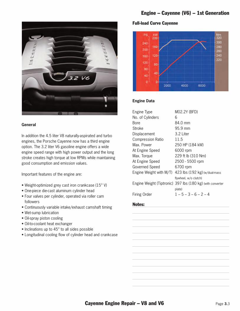
In addition the 4.5 liter V8 naturally-aspirated and turboengines, the Porsche Cayenne now has a third engineoption. The 3.2 liter V6 gasoline engine offers a wideengine speed range with high power output and the longstroke creates high torque at low RPMs while maintaininggood consumption and emission values.
Important features of the engine are:
• Weight-optimized grey cast iron crankcase (15° V)• One-piece die-cast aluminum cylinder head • Four valves per cylinder, operated via roller cam
followers• Continuously variable intake/exhaust camshaft timing• Wet-sump lubrication• Oil-spray piston cooling• Oil-to-coolant heat exchanger• Inclinations up to 45° to all sides possible• Longitudinal cooling flow of cylinder head and crankcase
Full-load Curve Cayenne
Engine Data
Engine Type M02.2Y (BFD)No. of Cylinders 6Bore 84.0 mmStroke 95.9 mmDisplacement 3.2 LiterCompression Ratio 11.5Max. Power 250 HP (184 kW)At Engine Speed 6000 rpmMax. Torque 229 ft lb (310 Nm)At Engine Speed 2500 - 5500 rpmGoverned Speed 6700 rpmEngine Weight with M/T) 423 lbs (192 kg) (w/dual-mass
flywheel, w/o clutch)
Engine Weight (Tiptronic) 397 lbs (180 kg) (with converter
plate)
Firing Order 1 – 5 – 3 – 6 – 2 – 4
Notes:
Page 3.4 Cayenne Engine Repair – V8 and V6
Engine – Cayenne (V6) – 1st Generation
Crankcase
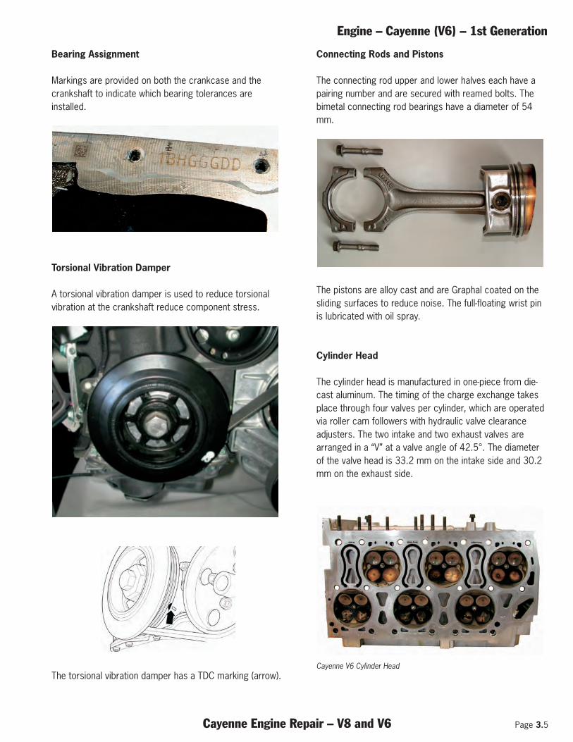
The weight-optimized crankcase with the cylinders ismanufactured from grey cast iron. The cylinders arearranged in a “V” at an angle of 15°, cylinder number 1 islocated on the front passenger side. Bores are at 7.5° togasket face.
Arrow shows the direction of travel.
Crankshaft
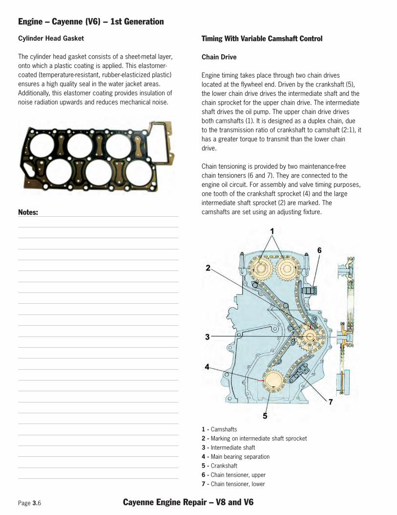
The drop-forged crankshaft is carried on seven bearings.Main bearing number 4 is designed as an axial-thrustbearing. The axial clearance is determined by two axial-thrust washers, which are seated in the bearing pedestal.The bimetal main bearings have a diameter of 60 mm.
Main bearing cap number 4.
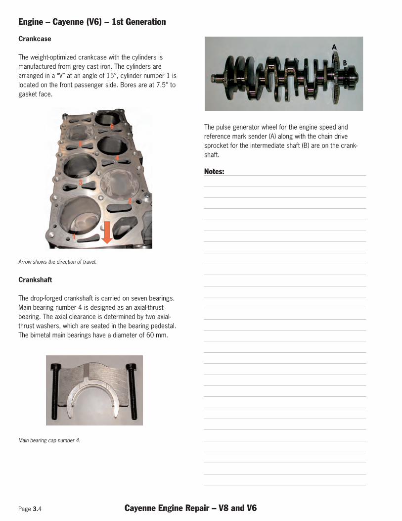
The pulse generator wheel for the engine speed andreference mark sender (A) along with the chain drivesprocket for the intermediate shaft (B) are on the crank-shaft.
Notes:
Engine – Cayenne (V6) – 1st Generation
Cayenne Engine Repair – V8 and V6 Page 3.5
Bearing Assignment
Markings are provided on both the crankcase and thecrankshaft to indicate which bearing tolerances areinstalled.
Torsional Vibration Damper
A torsional vibration damper is used to reduce torsionalvibration at the crankshaft reduce component stress.
The torsional vibration damper has a TDC marking (arrow).
Connecting Rods and Pistons
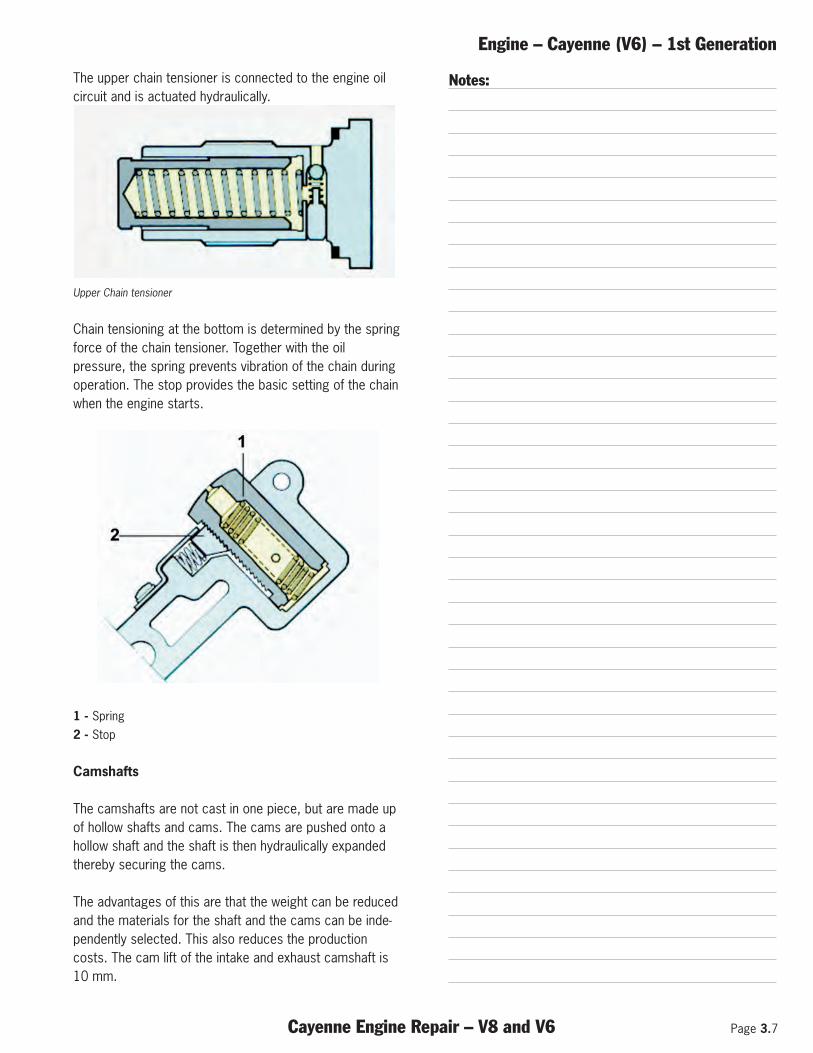
The connecting rod upper and lower halves each have apairing number and are secured with reamed bolts. Thebimetal connecting rod bearings have a diameter of 54mm.
The pistons are alloy cast and are Graphal coated on thesliding surfaces to reduce noise. The full-floating wrist pinis lubricated with oil spray.
Cylinder Head
The cylinder head is manufactured in one-piece from die-cast aluminum. The timing of the charge exchange takesplace through four valves per cylinder, which are operatedvia roller cam followers with hydraulic valve clearanceadjusters. The two intake and two exhaust valves arearranged in a “V” at a valve angle of 42.5°. The diameterof the valve head is 33.2 mm on the intake side and 30.2mm on the exhaust side.
Cayenne V6 Cylinder Head
Page 3.6 Cayenne Engine Repair – V8 and V6
Engine – Cayenne (V6) – 1st Generation
Cylinder Head Gasket
The cylinder head gasket consists of a sheet-metal layer,onto which a plastic coating is applied. This elastomer-coated (temperature-resistant, rubber-elasticized plastic)ensures a high quality seal in the water jacket areas.Additionally, this elastomer coating provides insulation ofnoise radiation upwards and reduces mechanical noise.
Notes:
Timing With Variable Camshaft Control
Chain Drive
Engine timing takes place through two chain driveslocated at the flywheel end. Driven by the crankshaft (5),the lower chain drive drives the intermediate shaft and thechain sprocket for the upper chain drive. The intermediateshaft drives the oil pump. The upper chain drive drivesboth camshafts (1). It is designed as a duplex chain, dueto the transmission ratio of crankshaft to camshaft (2:1), ithas a greater torque to transmit than the lower chaindrive.
Chain tensioning is provided by two maintenance-freechain tensioners (6 and 7). They are connected to theengine oil circuit. For assembly and valve timing purposes,one tooth of the crankshaft sprocket (4) and the largeintermediate shaft sprocket (2) are marked. Thecamshafts are set using an adjusting fixture.
1 - Camshafts2 - Marking on intermediate shaft sprocket3 - Intermediate shaft4 - Main bearing separation5 - Crankshaft6 - Chain tensioner, upper7 - Chain tensioner, lower
Engine – Cayenne (V6) – 1st Generation
Cayenne Engine Repair – V8 and V6 Page 3.7
The upper chain tensioner is connected to the engine oilcircuit and is actuated hydraulically.
Upper Chain tensioner
Chain tensioning at the bottom is determined by the springforce of the chain tensioner. Together with the oilpressure, the spring prevents vibration of the chain duringoperation. The stop provides the basic setting of the chainwhen the engine starts.
1 - Spring2 - Stop
Camshafts
The camshafts are not cast in one piece, but are made upof hollow shafts and cams. The cams are pushed onto ahollow shaft and the shaft is then hydraulically expandedthereby securing the cams.
The advantages of this are that the weight can be reducedand the materials for the shaft and the cams can be inde-pendently selected. This also reduces the productioncosts. The cam lift of the intake and exhaust camshaft is10 mm.
Notes:
Page 3.8 Cayenne Engine Repair – V8 and V6
Engine – Cayenne (V6) – 1st Generation
Variable Camshaft Control
General
The variable camshaft control of the inlet and exhaustshaft is based on the principle of the vane cell adjuster.The control unit determines the current position of thecamshaft in relation to the crankshaft (actual angle) usingthe engine speed and hall sensor signal. The positioncontrol in the control unit receives the desired angle viathe programmed map values (engine speed, load, enginetemperature). If the desired angle and actual angle differ, acontroller in the DME control unit actuates a solenoidhydraulic valve according to the desired position. Theadjustment angle is 52° crankshaft angle on the intakeside and 22° on the exhaust side.
Operation
When idling, the inlet camshaft is adjusted so that theinlet valves open late and consequently close late. Theexhaust camshaft is adjusted so that the exhaust valvesclose well before TDC. This results in a stable idling speeddue to the low residual gas content during combustion.
To achieve good performance at high engine speeds, theexhaust valves are opened late. This allows the combus-tion expansion to act on the piston longer. The intake valveopens after TDC and closes late after BDC. This utilizesthe dynamic ram effect of the incoming air to increasepower output.
To produce maximum torque, a high volumetric efficiencyof the cylinders must be achieved. For this, the intakevalves must be opened early. Since they open earlier, theyalso close earlier, which prevents expulsion of the freshgases. The exhaust valve closes shortly before TDC.
During the adjustment of the intake and exhaustcamshafts, an internal exhaust gas recirculation takesplace. This produces an exhaust gas transfer fromexhaust to intake port during valve overlap (inlet andexhaust valves are open). The amount of recirculatedexhaust gas during the internal exhaust gas recirculation isdetermined by the amount of valve overlap. Therefore, theintake camshaft is adjusted so that the intake valves openwell before TDC and the exhaust valves close shortlybefore TDC. Consequently, both valves are open andexhaust gas is recirculated.
Notes:
Engine – Cayenne (V6) – 1st Generation
Cayenne Engine Repair – V8 and V6 Page 3.9
Camshafts
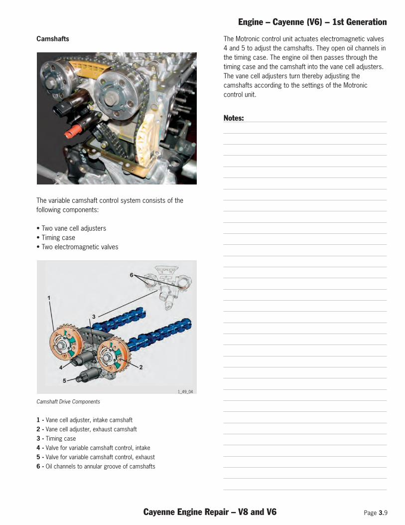
The variable camshaft control system consists of thefollowing components:
• Two vane cell adjusters • Timing case• Two electromagnetic valves
Camshaft Drive Components
1 - Vane cell adjuster, intake camshaft2 - Vane cell adjuster, exhaust camshaft3 - Timing case4 - Valve for variable camshaft control, intake5 - Valve for variable camshaft control, exhaust6 - Oil channels to annular groove of camshafts
The Motronic control unit actuates electromagnetic valves4 and 5 to adjust the camshafts. They open oil channels inthe timing case. The engine oil then passes through thetiming case and the camshaft into the vane cell adjusters.The vane cell adjusters turn thereby adjusting thecamshafts according to the settings of the Motroniccontrol unit.
Notes:
1_49_04
Page 3.10 Cayenne Engine Repair – V8 and V6
Engine – Cayenne (V6) – 1st Generation
Belt Drive
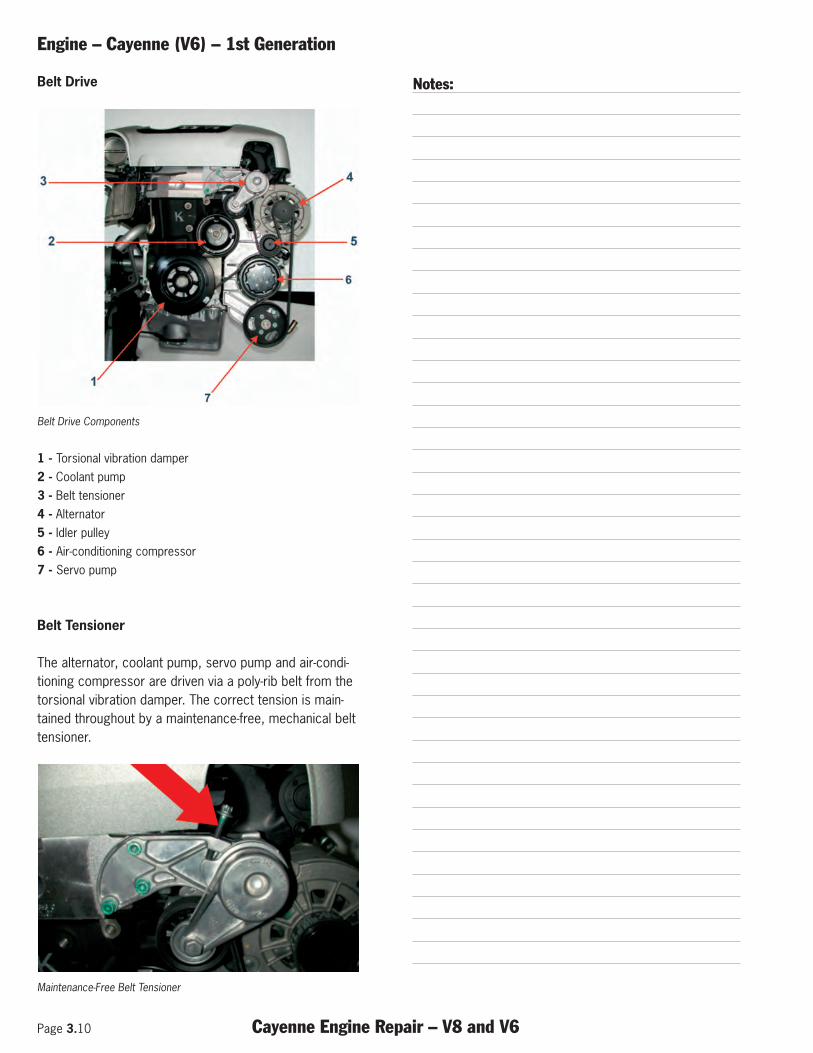
Belt Drive Components
1 - Torsional vibration damper2 - Coolant pump3 - Belt tensioner4 - Alternator5 - Idler pulley6 - Air-conditioning compressor7 - Servo pump
Belt Tensioner
The alternator, coolant pump, servo pump and air-condi-tioning compressor are driven via a poly-rib belt from thetorsional vibration damper. The correct tension is main-tained throughout by a maintenance-free, mechanical belttensioner.
Maintenance-Free Belt Tensioner
Notes:
Engine – Cayenne (V6) – 1st Generation
Cayenne Engine Repair – V8 and V6 Page 3.11
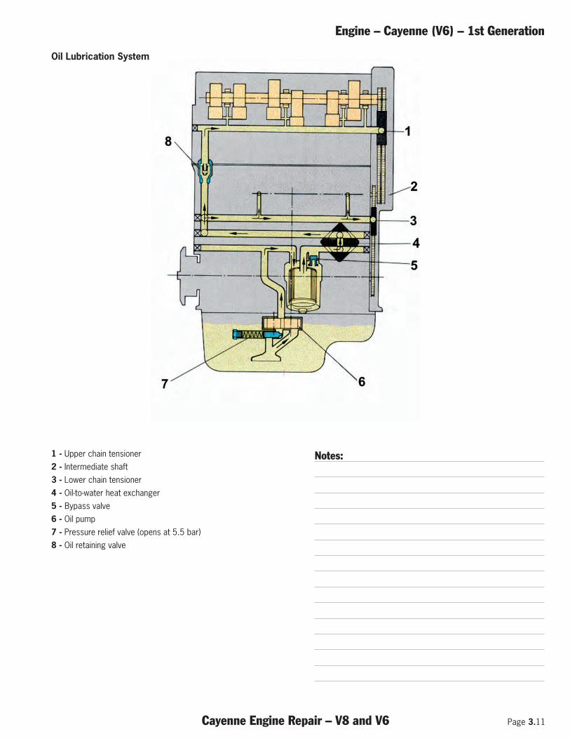
1 - Upper chain tensioner2 - Intermediate shaft3 - Lower chain tensioner4 - Oil-to-water heat exchanger5 - Bypass valve6 - Oil pump7 - Pressure relief valve (opens at 5.5 bar)8 - Oil retaining valve
Notes:
Oil Lubrication System
Page 3.12 Cayenne Engine Repair – V8 and V6
Engine – Cayenne (V6) – 1st Generation
Oil Pump
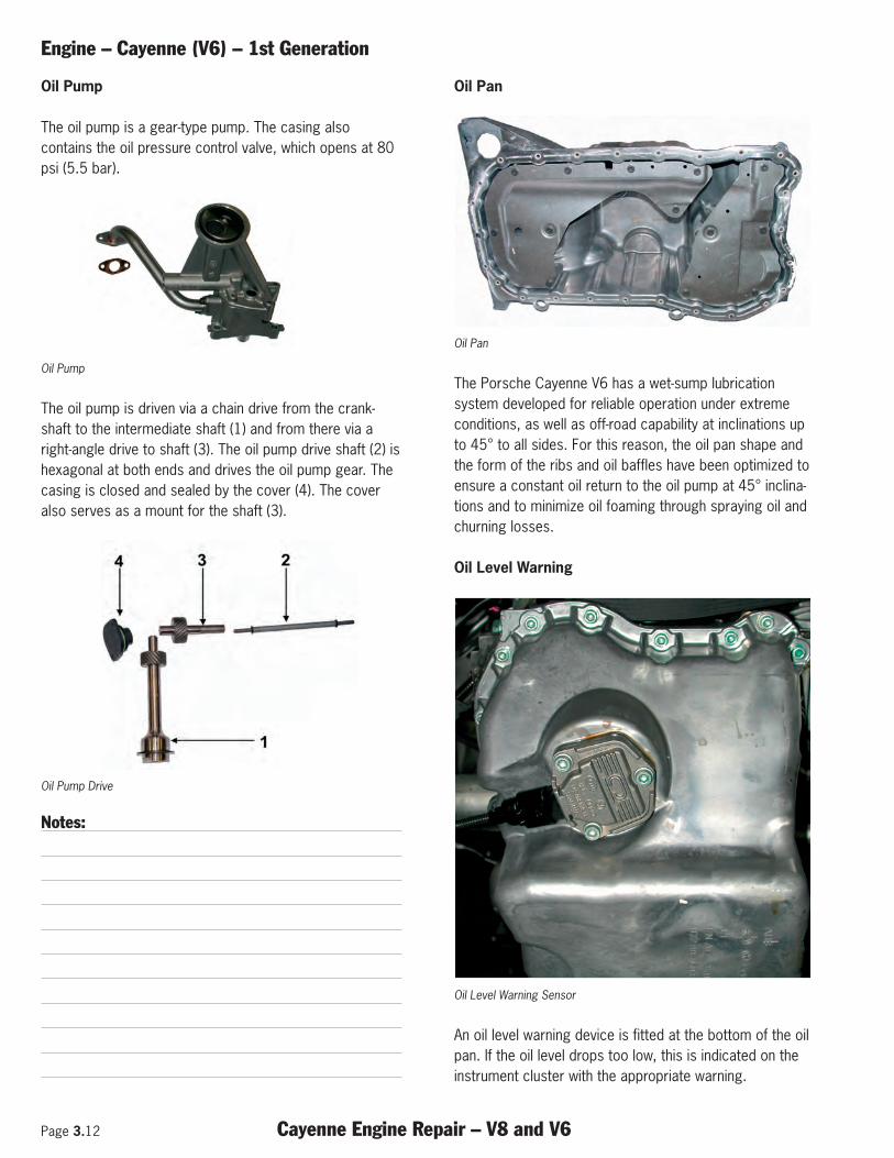
The oil pump is a gear-type pump. The casing alsocontains the oil pressure control valve, which opens at 80psi (5.5 bar).
Oil Pump
The oil pump is driven via a chain drive from the crank-shaft to the intermediate shaft (1) and from there via aright-angle drive to shaft (3). The oil pump drive shaft (2) ishexagonal at both ends and drives the oil pump gear. Thecasing is closed and sealed by the cover (4). The coveralso serves as a mount for the shaft (3).
Oil Pump Drive
Notes:
Oil Pan
Oil Pan
The Porsche Cayenne V6 has a wet-sump lubricationsystem developed for reliable operation under extremeconditions, as well as off-road capability at inclinations upto 45° to all sides. For this reason, the oil pan shape andthe form of the ribs and oil baffles have been optimized toensure a constant oil return to the oil pump at 45° inclina-tions and to minimize oil foaming through spraying oil andchurning losses.
Oil Level Warning
Oil Level Warning Sensor
An oil level warning device is fitted at the bottom of the oilpan. If the oil level drops too low, this is indicated on theinstrument cluster with the appropriate warning.
Engine – Cayenne (V6) – 1st Generation
Cayenne Engine Repair – V8 and V6 Page 3.13
Oil Pressure Switch
Oil Pressure Switch (Arrow)
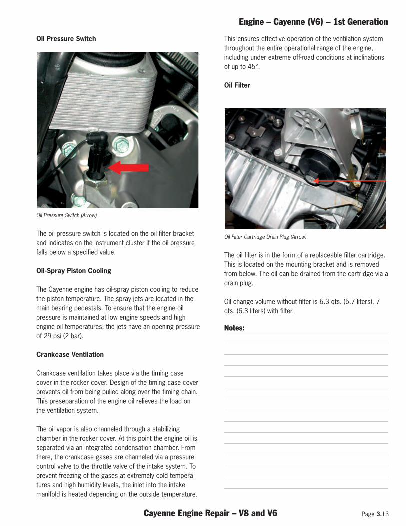
The oil pressure switch is located on the oil filter bracketand indicates on the instrument cluster if the oil pressurefalls below a specified value.
Oil-Spray Piston Cooling
The Cayenne engine has oil-spray piston cooling to reducethe piston temperature. The spray jets are located in themain bearing pedestals. To ensure that the engine oilpressure is maintained at low engine speeds and highengine oil temperatures, the jets have an opening pressureof 29 psi (2 bar).
Crankcase Ventilation
Crankcase ventilation takes place via the timing casecover in the rocker cover. Design of the timing case coverprevents oil from being pulled along over the timing chain.This preseparation of the engine oil relieves the load onthe ventilation system.
The oil vapor is also channeled through a stabilizingchamber in the rocker cover. At this point the engine oil isseparated via an integrated condensation chamber. Fromthere, the crankcase gases are channeled via a pressurecontrol valve to the throttle valve of the intake system. Toprevent freezing of the gases at extremely cold tempera-tures and high humidity levels, the inlet into the intakemanifold is heated depending on the outside temperature.
This ensures effective operation of the ventilation systemthroughout the entire operational range of the engine,including under extreme off-road conditions at inclinationsof up to 45°.
Oil Filter
Oil Filter Cartridge Drain Plug (Arrow)
The oil filter is in the form of a replaceable filter cartridge.This is located on the mounting bracket and is removedfrom below. The oil can be drained from the cartridge via adrain plug.
Oil change volume without filter is 6.3 qts. (5.7 liters), 7qts. (6.3 liters) with filter.
Notes:
Page 3.14 Cayenne Engine Repair – V8 and V6
Engine – Cayenne (V6) – 1st Generation
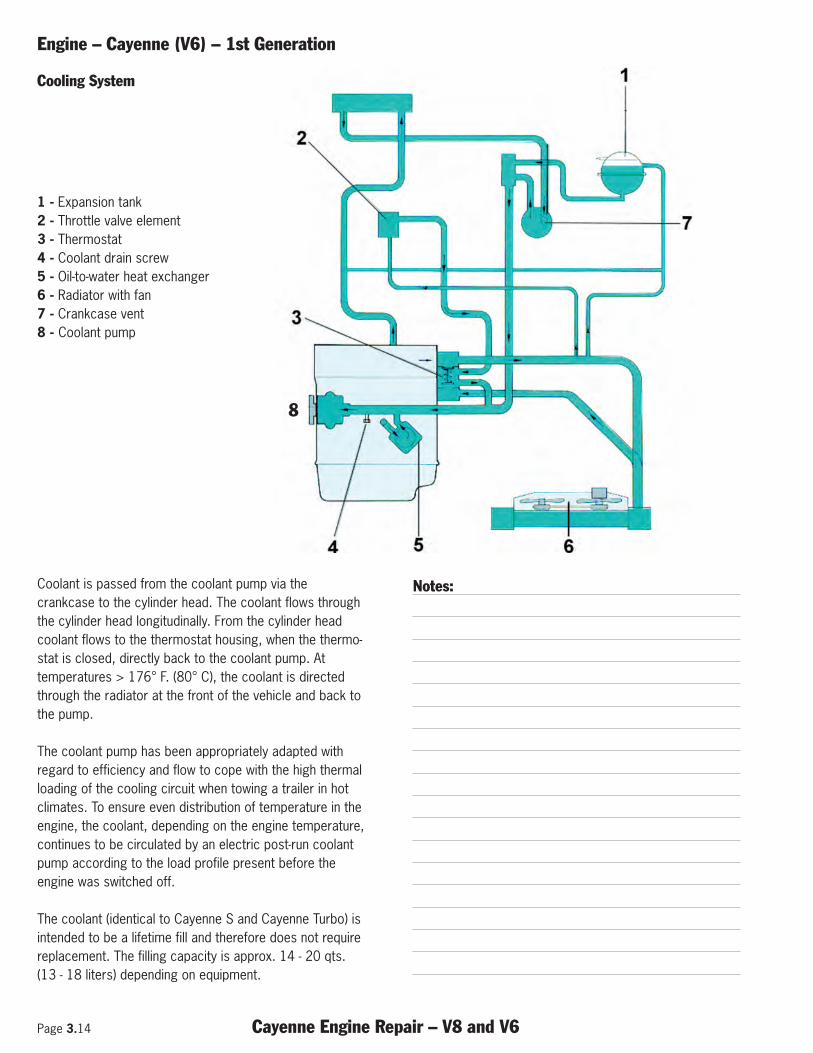
Coolant is passed from the coolant pump via thecrankcase to the cylinder head. The coolant flows throughthe cylinder head longitudinally. From the cylinder headcoolant flows to the thermostat housing, when the thermo-stat is closed, directly back to the coolant pump. Attemperatures > 176° F. (80° C), the coolant is directedthrough the radiator at the front of the vehicle and back tothe pump.
The coolant pump has been appropriately adapted withregard to efficiency and flow to cope with the high thermalloading of the cooling circuit when towing a trailer in hotclimates. To ensure even distribution of temperature in theengine, the coolant, depending on the engine temperature,continues to be circulated by an electric post-run coolantpump according to the load profile present before theengine was switched off.
The coolant (identical to Cayenne S and Cayenne Turbo) isintended to be a lifetime fill and therefore does not requirereplacement. The filling capacity is approx. 14 - 20 qts.(13 - 18 liters) depending on equipment.
Notes:
Cooling System
1 - Expansion tank2 - Throttle valve element3 - Thermostat4 - Coolant drain screw5 - Oil-to-water heat exchanger6 - Radiator with fan7 - Crankcase vent8 - Coolant pump
8
Engine – Cayenne S/T – 2nd Generation
Cayenne Engine Repair – V8 and V6 Page 4.1
Subject Page
General . . . . . . . . . . . . . . . . . . . . . . . . . . . . . . . . . . . . . . . . . . . . . . . . . . . . . . . . . . . . . . . . . .3
Cayenne S Engine Data . . . . . . . . . . . . . . . . . . . . . . . . . . . . . . . . . . . . . . . . . . . . . . . . . . . . . .3
Cayenne Turbo Engine Data . . . . . . . . . . . . . . . . . . . . . . . . . . . . . . . . . . . . . . . . . . . . . . . . . . .4
Crankcase . . . . . . . . . . . . . . . . . . . . . . . . . . . . . . . . . . . . . . . . . . . . . . . . . . . . . . . . . . . . . . . .4
Crankshaft . . . . . . . . . . . . . . . . . . . . . . . . . . . . . . . . . . . . . . . . . . . . . . . . . . . . . . . . . . . . . . . .5
Torsional Vibration Balancer . . . . . . . . . . . . . . . . . . . . . . . . . . . . . . . . . . . . . . . . . . . . . . . . . . .5
Connecting Rods . . . . . . . . . . . . . . . . . . . . . . . . . . . . . . . . . . . . . . . . . . . . . . . . . . . . . . . . . . .5
Pistons . . . . . . . . . . . . . . . . . . . . . . . . . . . . . . . . . . . . . . . . . . . . . . . . . . . . . . . . . . . . . . . . . .6
Cylinder Head . . . . . . . . . . . . . . . . . . . . . . . . . . . . . . . . . . . . . . . . . . . . . . . . . . . . . . . . . . . . .6
Valves, Valve Springs . . . . . . . . . . . . . . . . . . . . . . . . . . . . . . . . . . . . . . . . . . . . . . . . . . . . . . .10
Vacuum Pump . . . . . . . . . . . . . . . . . . . . . . . . . . . . . . . . . . . . . . . . . . . . . . . . . . . . . . . . . . . .11
Belt Drive . . . . . . . . . . . . . . . . . . . . . . . . . . . . . . . . . . . . . . . . . . . . . . . . . . . . . . . . . . . . . . .11
Oil Lubrication System . . . . . . . . . . . . . . . . . . . . . . . . . . . . . . . . . . . . . . . . . . . . . . . . . . . . . .13
Cayenne S Cooling System . . . . . . . . . . . . . . . . . . . . . . . . . . . . . . . . . . . . . . . . . . . . . . . . . . .17
Cayenne Turbo Cooling System . . . . . . . . . . . . . . . . . . . . . . . . . . . . . . . . . . . . . . . . . . . . . . . .18

Page 4.2 Cayenne Engine Repair – V8 and V6
Engine – Cayenne S/T – 2nd Generation
Notes:
Engine – Cayenne S/T – 2nd Generation
Cayenne Engine Repair – V8 and V6 Page 4.3
1 - Engine M 48.01/51
General
Completely new engines have been developed for theCayenne S and Cayenne Turbo for the 2008 model year.
The main development aims were:
• More power and torque, while at the same time, • Improving fuel economy and, • Reducing the weight of the engine compared to
previous engines.
These development aims have essentially beenachieved due to the following enhancements andnew technologies:
• Larger displacement • Direct fuel injection (DFI)• Sport button as standard• VarioCam Plus• Demand controlled oil pump
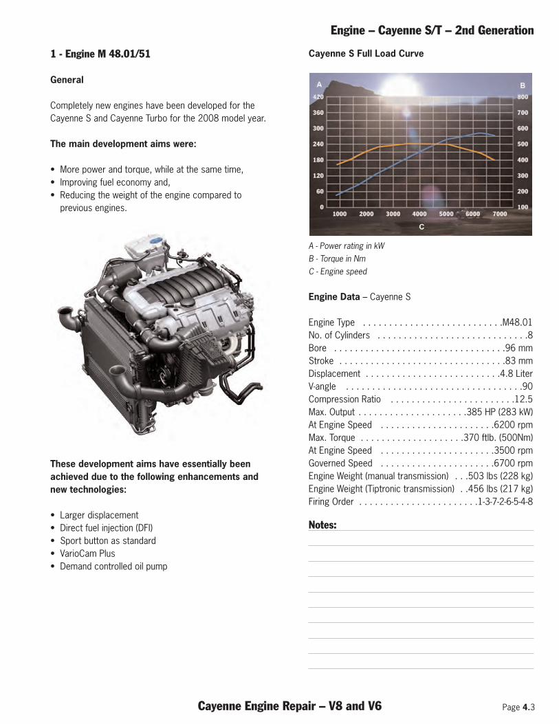
Cayenne S Full Load Curve
A - Power rating in kW B - Torque in Nm C - Engine speed
Engine Data – Cayenne S
Engine Type . . . . . . . . . . . . . . . . . . . . . . . . . . .M48.01 No. of Cylinders . . . . . . . . . . . . . . . . . . . . . . . . . . . . .8 Bore . . . . . . . . . . . . . . . . . . . . . . . . . . . . . . . . .96 mm Stroke . . . . . . . . . . . . . . . . . . . . . . . . . . . . . . . .83 mm Displacement . . . . . . . . . . . . . . . . . . . . . . . . . .4.8 Liter V-angle . . . . . . . . . . . . . . . . . . . . . . . . . . . . . . . . . .90 Compression Ratio . . . . . . . . . . . . . . . . . . . . . . . .12.5 Max. Output . . . . . . . . . . . . . . . . . . . . .385 HP (283 kW) At Engine Speed . . . . . . . . . . . . . . . . . . . . . .6200 rpm Max. Torque . . . . . . . . . . . . . . . . . . . .370 ftlb. (500Nm) At Engine Speed . . . . . . . . . . . . . . . . . . . . . .3500 rpm Governed Speed . . . . . . . . . . . . . . . . . . . . . .6700 rpm Engine Weight (manual transmission) . . .503 lbs (228 kg) Engine Weight (Tiptronic transmission) . .456 lbs (217 kg)Firing Order . . . . . . . . . . . . . . . . . . . . . . .1-3-7-2-6-5-4-8
Notes:
Page 4.4 Cayenne Engine Repair – V8 and V6
Engine – Cayenne S/T – 2nd Generation
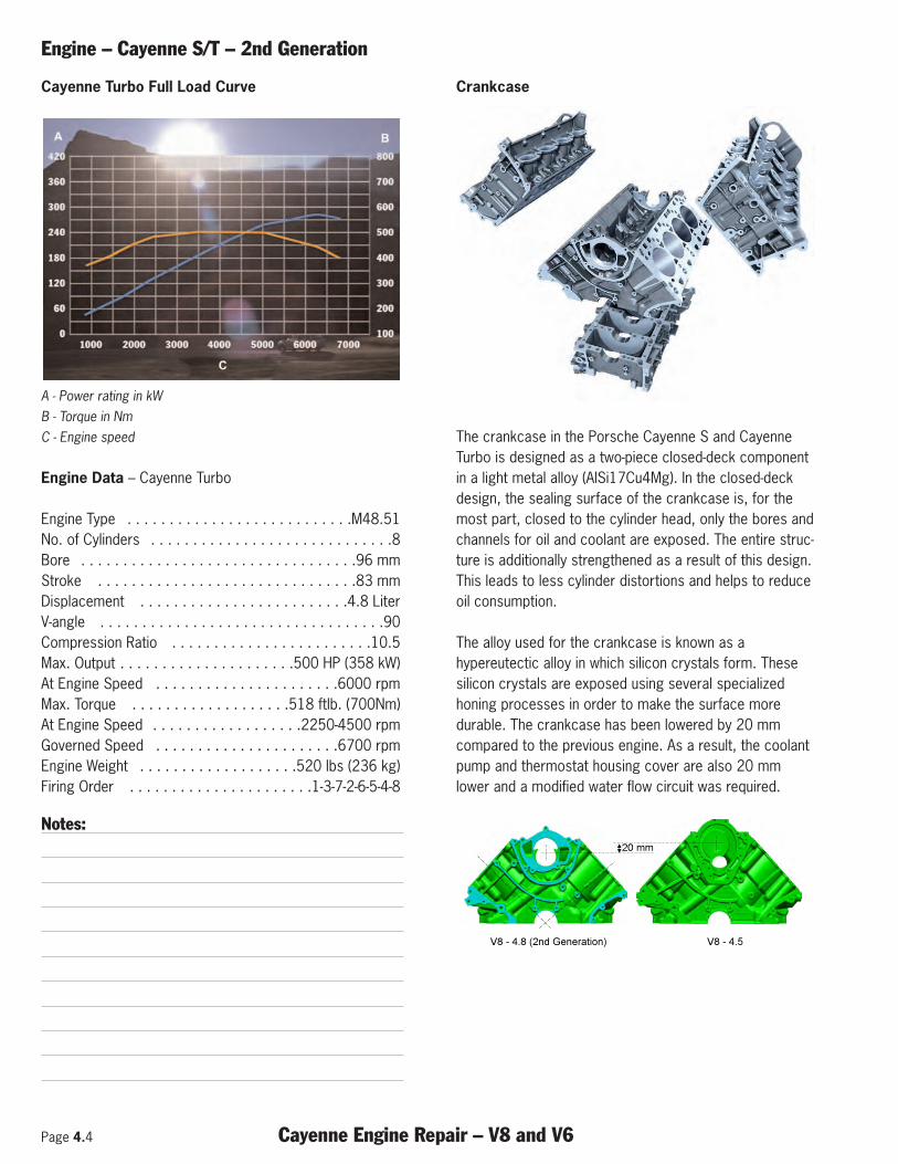
Cayenne Turbo Full Load Curve
A - Power rating in kW B - Torque in Nm C - Engine speed
Engine Data – Cayenne Turbo
Engine Type . . . . . . . . . . . . . . . . . . . . . . . . . . .M48.51No. of Cylinders . . . . . . . . . . . . . . . . . . . . . . . . . . . . .8Bore . . . . . . . . . . . . . . . . . . . . . . . . . . . . . . . . .96 mmStroke . . . . . . . . . . . . . . . . . . . . . . . . . . . . . . .83 mmDisplacement . . . . . . . . . . . . . . . . . . . . . . . . .4.8 LiterV-angle . . . . . . . . . . . . . . . . . . . . . . . . . . . . . . . . . .90Compression Ratio . . . . . . . . . . . . . . . . . . . . . . . .10.5Max. Output . . . . . . . . . . . . . . . . . . . . .500 HP (358 kW)At Engine Speed . . . . . . . . . . . . . . . . . . . . . .6000 rpmMax. Torque . . . . . . . . . . . . . . . . . . .518 ftlb. (700Nm)At Engine Speed . . . . . . . . . . . . . . . . . .2250-4500 rpmGoverned Speed . . . . . . . . . . . . . . . . . . . . . .6700 rpmEngine Weight . . . . . . . . . . . . . . . . . . .520 lbs (236 kg)Firing Order . . . . . . . . . . . . . . . . . . . . . .1-3-7-2-6-5-4-8
Notes:
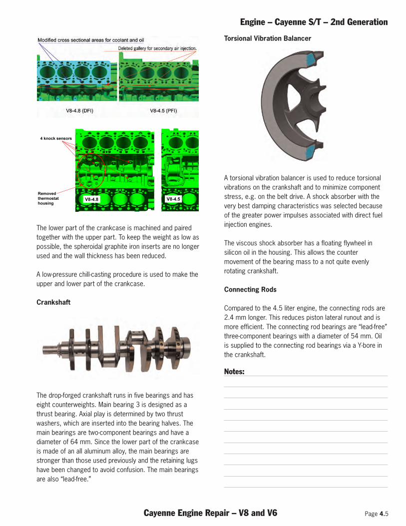
Crankcase
The crankcase in the Porsche Cayenne S and CayenneTurbo is designed as a two-piece closed-deck componentin a light metal alloy (AlSi17Cu4Mg). In the closed-deck design, the sealing surface of the crankcase is, for themost part, closed to the cylinder head, only the bores andchannels for oil and coolant are exposed. The entire struc-ture is additionally strengthened as a result of this design.This leads to less cylinder distortions and helps to reduceoil consumption.
The alloy used for the crankcase is known as ahypereutectic alloy in which silicon crystals form. Thesesilicon crystals are exposed using several specializedhoning processes in order to make the surface moredurable. The crankcase has been lowered by 20 mmcompared to the previous engine. As a result, the coolantpump and thermostat housing cover are also 20 mmlower and a modified water flow circuit was required.
20 mm
V8 - 4.8 (2nd Generation) V8 - 4.5
9
Engine – Cayenne S/T – 2nd Generation
Cayenne Engine Repair – V8 and V6 Page 4.5
The lower part of the crankcase is machined and pairedtogether with the upper part. To keep the weight as low aspossible, the spheroidal graphite iron inserts are no longerused and the wall thickness has been reduced.
A low-pressure chill-casting procedure is used to make theupper and lower part of the crankcase.
Crankshaft
The drop-forged crankshaft runs in five bearings and haseight counterweights. Main bearing 3 is designed as athrust bearing. Axial play is determined by two thrustwashers, which are inserted into the bearing halves. Themain bearings are two-component bearings and have a diameter of 64 mm. Since the lower part of the crankcaseis made of an all aluminum alloy, the main bearings arestronger than those used previously and the retaining lugshave been changed to avoid confusion. The main bearingsare also “lead-free.”
Torsional Vibration Balancer
A torsional vibration balancer is used to reduce torsionalvibrations on the crankshaft and to minimize componentstress, e.g. on the belt drive. A shock absorber with thevery best damping characteristics was selected becauseof the greater power impulses associated with direct fuelinjection engines.
The viscous shock absorber has a floating flywheel insilicon oil in the housing. This allows the countermovement of the bearing mass to a not quite evenlyrotating crankshaft.
Connecting Rods
Compared to the 4.5 liter engine, the connecting rods are2.4 mm longer. This reduces piston lateral runout and ismore efficient. The connecting rod bearings are “lead-free”three-component bearings with a diameter of 54 mm. Oilis supplied to the connecting rod bearings via a Y-bore inthe crankshaft.
Notes:
4 knock sensors
Removed
thermostat
housingV8-4.8 V8-4.5
9
Page 4.6 Cayenne Engine Repair – V8 and V6
Engine – Cayenne S/T – 2nd Generation
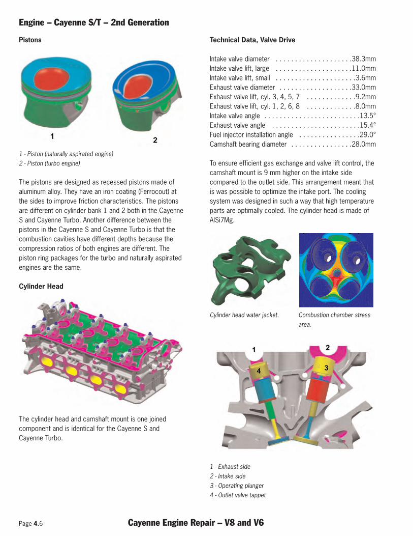
Pistons
1 - Piston (naturally aspirated engine) 2 - Piston (turbo engine)
The pistons are designed as recessed pistons made ofaluminum alloy. They have an iron coating (Ferrocout) atthe sides to improve friction characteristics. The pistonsare different on cylinder bank 1 and 2 both in the CayenneS and Cayenne Turbo. Another difference between thepistons in the Cayenne S and Cayenne Turbo is that thecombustion cavities have different depths because thecompression ratios of both engines are different. Thepiston ring packages for the turbo and naturally aspiratedengines are the same.
Cylinder Head
The cylinder head and camshaft mount is one joinedcomponent and is identical for the Cayenne S andCayenne Turbo.
Technical Data, Valve Drive
Intake valve diameter . . . . . . . . . . . . . . . . . . . .38.3mmIntake valve lift, large . . . . . . . . . . . . . . . . . . . .11.0mmIntake valve lift, small . . . . . . . . . . . . . . . . . . . . .3.6mmExhaust valve diameter . . . . . . . . . . . . . . . . . . .33.0mmExhaust valve lift, cyl. 3, 4, 5, 7 . . . . . . . . . . . . .9.2mmExhaust valve lift, cyl. 1, 2, 6, 8 . . . . . . . . . . . . .8.0mmIntake valve angle . . . . . . . . . . . . . . . . . . . . . . . . .13.5°Exhaust valve angle . . . . . . . . . . . . . . . . . . . . . . .15.4°Fuel injector installation angle . . . . . . . . . . . . . . . .29.0°Camshaft bearing diameter . . . . . . . . . . . . . . . .28.0mm
To ensure efficient gas exchange and valve lift control, thecamshaft mount is 9 mm higher on the intake sidecompared to the outlet side. This arrangement meant thatis was possible to optimize the intake port. The coolingsystem was designed in such a way that high temperatureparts are optimally cooled. The cylinder head is made ofAlSi7Mg.
Cylinder head water jacket. Combustion chamber stressarea.
1 - Exhaust side 2 - Intake side 3 - Operating plunger 4 - Outlet valve tappet
Engine – Cayenne S/T – 2nd Generation
Cayenne Engine Repair – V8 and V6 Page 4.7
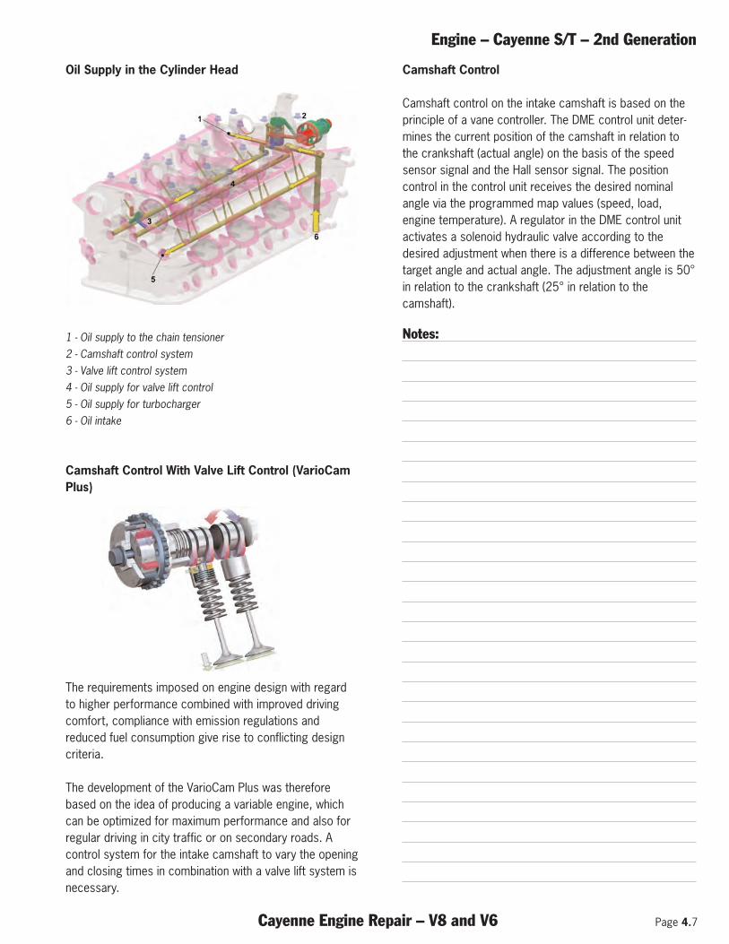
Oil Supply in the Cylinder Head
1 - Oil supply to the chain tensioner 2 - Camshaft control system 3 - Valve lift control system 4 - Oil supply for valve lift control 5 - Oil supply for turbocharger 6 - Oil intake
Camshaft Control With Valve Lift Control (VarioCamPlus)
The requirements imposed on engine design with regardto higher performance combined with improved drivingcomfort, compliance with emission regulations andreduced fuel consumption give rise to conflicting designcriteria.
The development of the VarioCam Plus was thereforebased on the idea of producing a variable engine, whichcan be optimized for maximum performance and also forregular driving in city traffic or on secondary roads. Acontrol system for the intake camshaft to vary the openingand closing times in combination with a valve lift system isnecessary.
Camshaft Control
Camshaft control on the intake camshaft is based on theprinciple of a vane controller. The DME control unit deter-mines the current position of the camshaft in relation tothe crankshaft (actual angle) on the basis of the speedsensor signal and the Hall sensor signal. The positioncontrol in the control unit receives the desired nominalangle via the programmed map values (speed, load,engine temperature). A regulator in the DME control unitactivates a solenoid hydraulic valve according to thedesired adjustment when there is a difference between thetarget angle and actual angle. The adjustment angle is 50°in relation to the crankshaft (25° in relation to thecamshaft).
Notes:
Page 4.8 Cayenne Engine Repair – V8 and V6
Engine – Cayenne S/T – 2nd Generation
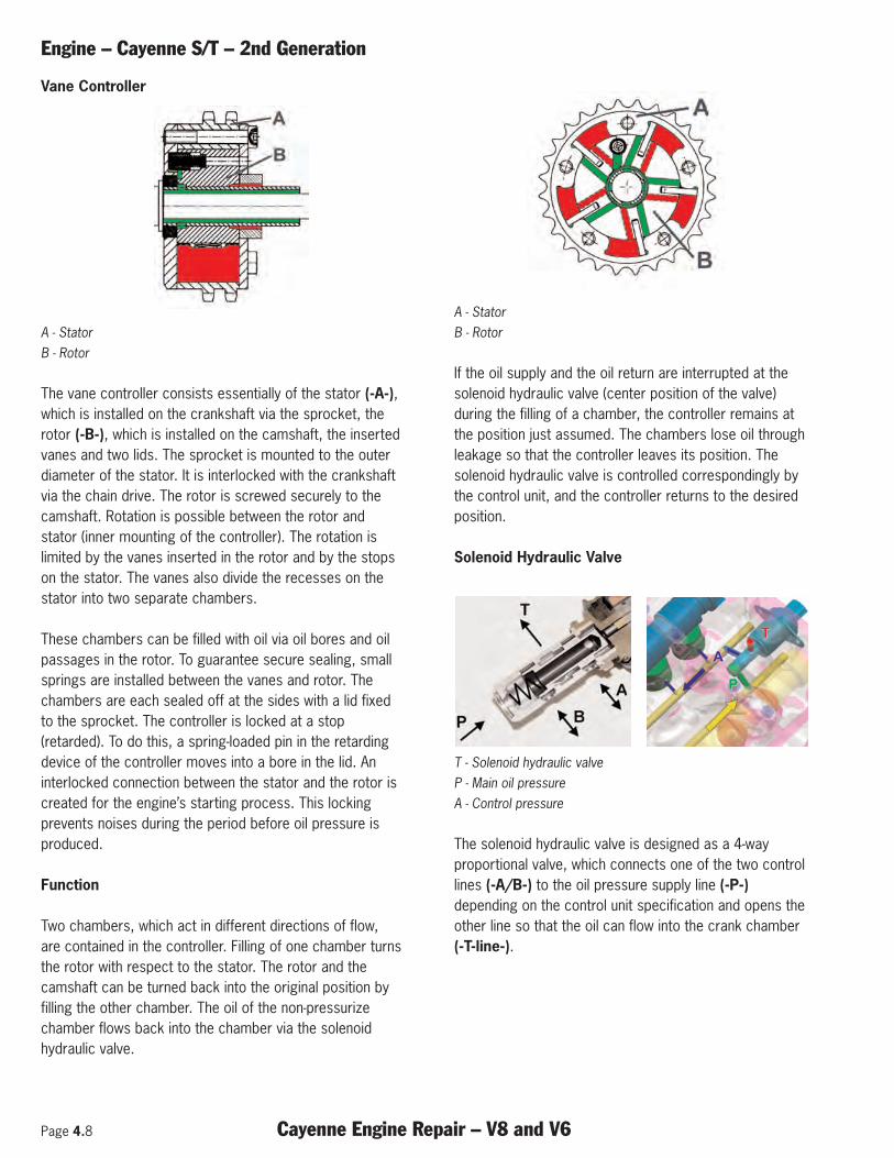
Vane Controller
A - Stator B - Rotor
The vane controller consists essentially of the stator (-A-),which is installed on the crankshaft via the sprocket, therotor (-B-), which is installed on the camshaft, the insertedvanes and two lids. The sprocket is mounted to the outerdiameter of the stator. It is interlocked with the crankshaftvia the chain drive. The rotor is screwed securely to thecamshaft. Rotation is possible between the rotor andstator (inner mounting of the controller). The rotation islimited by the vanes inserted in the rotor and by the stopson the stator. The vanes also divide the recesses on thestator into two separate chambers.
These chambers can be filled with oil via oil bores and oilpassages in the rotor. To guarantee secure sealing, smallsprings are installed between the vanes and rotor. Thechambers are each sealed off at the sides with a lid fixedto the sprocket. The controller is locked at a stop(retarded). To do this, a spring-loaded pin in the retardingdevice of the controller moves into a bore in the lid. Aninterlocked connection between the stator and the rotor iscreated for the engine’s starting process. This lockingprevents noises during the period before oil pressure isproduced.
Function
Two chambers, which act in different directions of flow,are contained in the controller. Filling of one chamber turnsthe rotor with respect to the stator. The rotor and thecamshaft can be turned back into the original position byfilling the other chamber. The oil of the non-pressurizechamber flows back into the chamber via the solenoidhydraulic valve.
A - Stator B - Rotor
If the oil supply and the oil return are interrupted at thesolenoid hydraulic valve (center position of the valve)during the filling of a chamber, the controller remains atthe position just assumed. The chambers lose oil throughleakage so that the controller leaves its position. Thesolenoid hydraulic valve is controlled correspondingly bythe control unit, and the controller returns to the desiredposition.
Solenoid Hydraulic Valve
T - Solenoid hydraulic valve P - Main oil pressure A - Control pressure
The solenoid hydraulic valve is designed as a 4-wayproportional valve, which connects one of the two controllines (-A/B-) to the oil pressure supply line (-P-)depending on the control unit specification and opens theother line so that the oil can flow into the crank chamber(-T-line-).
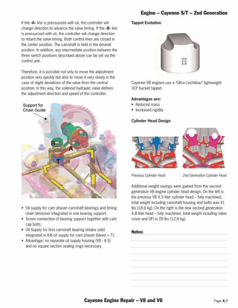
Engine – Cayenne S/T – 2nd Generation
Cayenne Engine Repair – V8 and V6 Page 4.9
If the -A- line is pressurized with oil, the controller willchange direction to advance the valve timing. If the -B- lineis pressurized with oil, the controller will change directionto retard the valve timing. Both control lines are closed inthe center position. The camshaft is held in the desiredposition. In addition, any intermediate position between thethree switch positions described above can be set via thecontrol unit.
Therefore, it is possible not only to move the adjustmentposition very quickly but also to move it very slowly in thecase of slight deviations of the valve from the centralposition. In this way, the solenoid hydraulic valve definesthe adjustment direction and speed of the controller.
• Oil supply for cam phaser camshaft bearings and timingchain tensioner integrated in one bearing support.
• Screw connection of bearing support together with camcap bolts.
• Oil Supply for first camshaft bearing (intake side)integrated in A-B oil supply for cam phaser (bleed > T).
• Advantage: no separate oil supply housing (V8 - 4.5)and no square section sealing rings necessary.
Tappet Evolution
Cayenne V8 engines use a “Ultra Leichtbau” lightweight3CF bucket tappet.
Advantages are:• Reduced mass• Increased rigidity
Cylinder Head Design
Previous Cylinder Head 2nd Generation Cylinder Head
Additional weight savings were gained from the secondgeneration V8 engine cylinder head design. On the left isthe previous V8 4.5 liter cylinder head – fully machined,total weight including camshaft housing and bolts was 41lbs (18.6 kg). On the right is the new second generation4.8 liter head – fully machined, total weight including valvecover and DFI is 28 lbs (12.6 kg).
Notes:
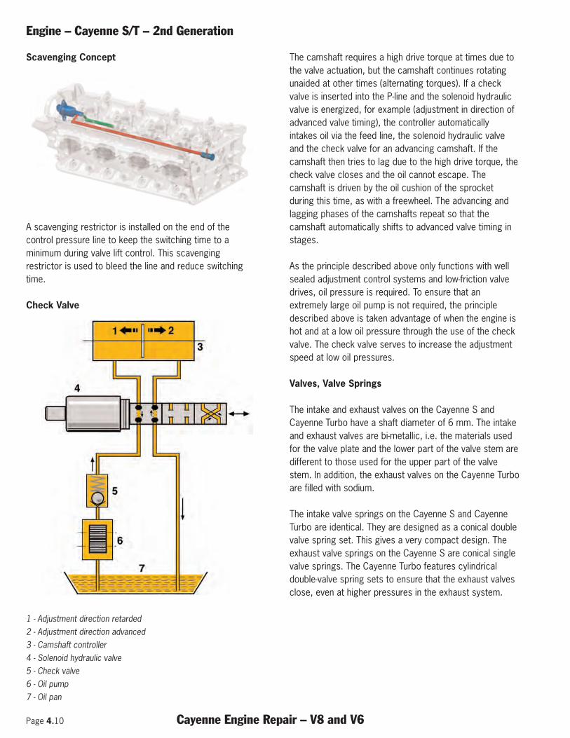
Page 4.10 Cayenne Engine Repair – V8 and V6
Engine – Cayenne S/T – 2nd Generation
Scavenging Concept
A scavenging restrictor is installed on the end of thecontrol pressure line to keep the switching time to aminimum during valve lift control. This scavengingrestrictor is used to bleed the line and reduce switchingtime.
Check Valve
1 - Adjustment direction retarded 2 - Adjustment direction advanced 3 - Camshaft controller 4 - Solenoid hydraulic valve 5 - Check valve 6 - Oil pump 7 - Oil pan
The camshaft requires a high drive torque at times due tothe valve actuation, but the camshaft continues rotatingunaided at other times (alternating torques). If a checkvalve is inserted into the P-line and the solenoid hydraulicvalve is energized, for example (adjustment in direction ofadvanced valve timing), the controller automaticallyintakes oil via the feed line, the solenoid hydraulic valveand the check valve for an advancing camshaft. If thecamshaft then tries to lag due to the high drive torque, thecheck valve closes and the oil cannot escape. Thecamshaft is driven by the oil cushion of the sprocketduring this time, as with a freewheel. The advancing andlagging phases of the camshafts repeat so that thecamshaft automatically shifts to advanced valve timing instages.
As the principle described above only functions with wellsealed adjustment control systems and low-friction valvedrives, oil pressure is required. To ensure that anextremely large oil pump is not required, the principledescribed above is taken advantage of when the engine ishot and at a low oil pressure through the use of the checkvalve. The check valve serves to increase the adjustmentspeed at low oil pressures.
Valves, Valve Springs
The intake and exhaust valves on the Cayenne S andCayenne Turbo have a shaft diameter of 6 mm. The intakeand exhaust valves are bi-metallic, i.e. the materials usedfor the valve plate and the lower part of the valve stem aredifferent to those used for the upper part of the valvestem. In addition, the exhaust valves on the Cayenne Turboare filled with sodium.
The intake valve springs on the Cayenne S and CayenneTurbo are identical. They are designed as a conical doublevalve spring set. This gives a very compact design. Theexhaust valve springs on the Cayenne S are conical singlevalve springs. The Cayenne Turbo features cylindricaldouble-valve spring sets to ensure that the exhaust valvesclose, even at higher pressures in the exhaust system.
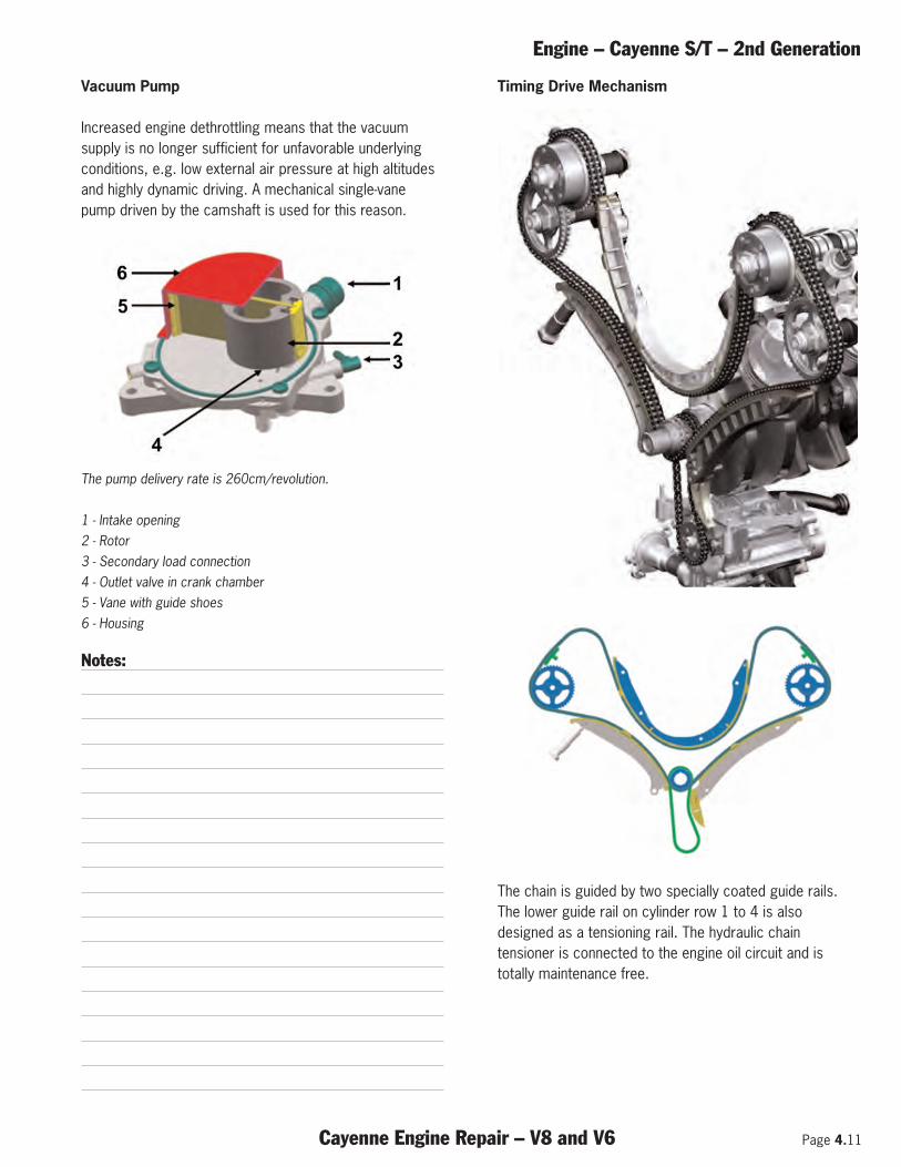
Engine – Cayenne S/T – 2nd Generation
Cayenne Engine Repair – V8 and V6 Page 4.11
Vacuum Pump
Increased engine dethrottling means that the vacuumsupply is no longer sufficient for unfavorable underlyingconditions, e.g. low external air pressure at high altitudesand highly dynamic driving. A mechanical single-vanepump driven by the camshaft is used for this reason.
The pump delivery rate is 260cm/revolution.
1 - Intake opening 2 - Rotor 3 - Secondary load connection 4 - Outlet valve in crank chamber 5 - Vane with guide shoes 6 - Housing
Notes:
Timing Drive Mechanism
The chain is guided by two specially coated guide rails.The lower guide rail on cylinder row 1 to 4 is alsodesigned as a tensioning rail. The hydraulic chaintensioner is connected to the engine oil circuit and istotally maintenance free.
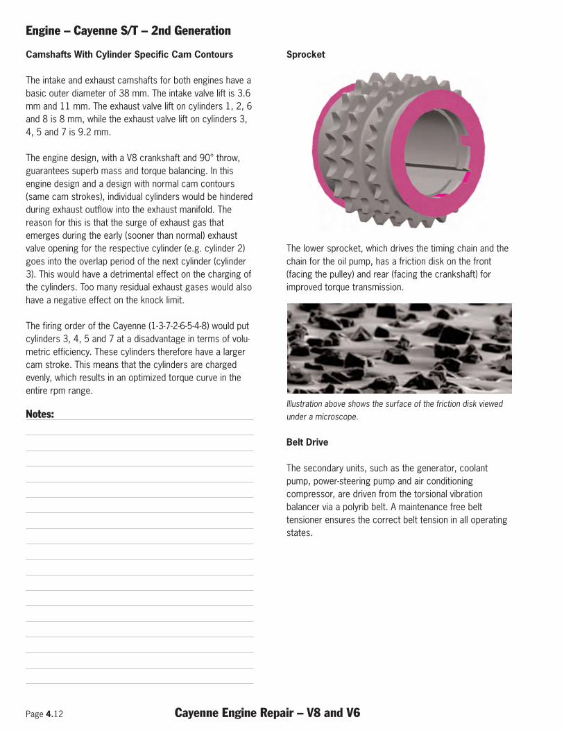
Page 4.12 Cayenne Engine Repair – V8 and V6
Engine – Cayenne S/T – 2nd Generation
Camshafts With Cylinder Specific Cam Contours
The intake and exhaust camshafts for both engines have abasic outer diameter of 38 mm. The intake valve lift is 3.6mm and 11 mm. The exhaust valve lift on cylinders 1, 2, 6and 8 is 8 mm, while the exhaust valve lift on cylinders 3,4, 5 and 7 is 9.2 mm.
The engine design, with a V8 crankshaft and 90° throw,guarantees superb mass and torque balancing. In thisengine design and a design with normal cam contours(same cam strokes), individual cylinders would be hinderedduring exhaust outflow into the exhaust manifold. Thereason for this is that the surge of exhaust gas thatemerges during the early (sooner than normal) exhaustvalve opening for the respective cylinder (e.g. cylinder 2)goes into the overlap period of the next cylinder (cylinder3). This would have a detrimental effect on the charging ofthe cylinders. Too many residual exhaust gases would alsohave a negative effect on the knock limit.
The firing order of the Cayenne (1-3-7-2-6-5-4-8) would putcylinders 3, 4, 5 and 7 at a disadvantage in terms of volu-metric efficiency. These cylinders therefore have a largercam stroke. This means that the cylinders are chargedevenly, which results in an optimized torque curve in theentire rpm range.
Notes:
Sprocket
The lower sprocket, which drives the timing chain and thechain for the oil pump, has a friction disk on the front(facing the pulley) and rear (facing the crankshaft) forimproved torque transmission.
Illustration above shows the surface of the friction disk viewedunder a microscope.
Belt Drive
The secondary units, such as the generator, coolantpump, power-steering pump and air conditioningcompressor, are driven from the torsional vibrationbalancer via a polyrib belt. A maintenance free belttensioner ensures the correct belt tension in all operatingstates.
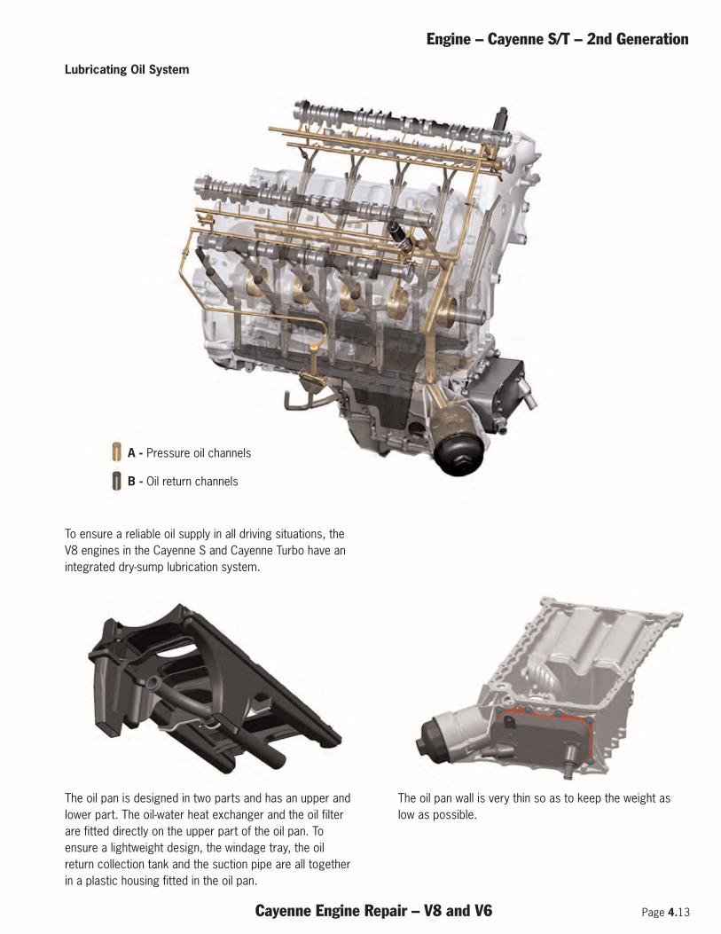
Engine – Cayenne S/T – 2nd Generation
Cayenne Engine Repair – V8 and V6 Page 4.13
To ensure a reliable oil supply in all driving situations, theV8 engines in the Cayenne S and Cayenne Turbo have anintegrated dry-sump lubrication system.
The oil pan is designed in two parts and has an upper andlower part. The oil-water heat exchanger and the oil filterare fitted directly on the upper part of the oil pan. Toensure a lightweight design, the windage tray, the oilreturn collection tank and the suction pipe are all togetherin a plastic housing fitted in the oil pan.
The oil pan wall is very thin so as to keep the weight aslow as possible.
Lubricating Oil System
A - Pressure oil channels
B - Oil return channels
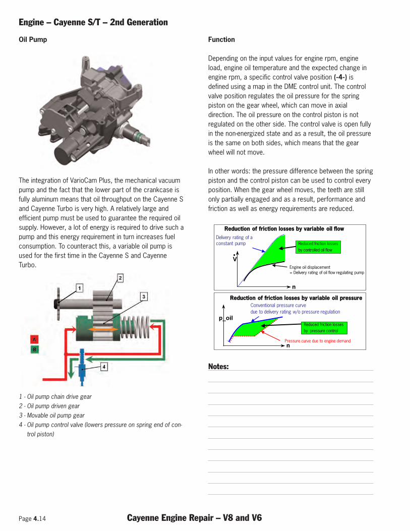
Page 4.14 Cayenne Engine Repair – V8 and V6
Engine – Cayenne S/T – 2nd Generation
Oil Pump
The integration of VarioCam Plus, the mechanical vacuumpump and the fact that the lower part of the crankcase isfully aluminum means that oil throughput on the Cayenne Sand Cayenne Turbo is very high. A relatively large andefficient pump must be used to guarantee the required oilsupply. However, a lot of energy is required to drive such apump and this energy requirement in turn increases fuelconsumption. To counteract this, a variable oil pump isused for the first time in the Cayenne S and CayenneTurbo.
1 - Oil pump chain drive gear2 - Oil pump driven gear3 - Movable oil pump gear4 - Oil pump control valve (lowers pressure on spring end of con-
trol piston)
Function
Depending on the input values for engine rpm, engineload, engine oil temperature and the expected change inengine rpm, a specific control valve position (-4-) isdefined using a map in the DME control unit. The controlvalve position regulates the oil pressure for the springpiston on the gear wheel, which can move in axialdirection. The oil pressure on the control piston is notregulated on the other side. The control valve is open fullyin the non-energized state and as a result, the oil pressureis the same on both sides, which means that the gearwheel will not move.
In other words: the pressure difference between the springpiston and the control piston can be used to control everyposition. When the gear wheel moves, the teeth are stillonly partially engaged and as a result, performance andfriction as well as energy requirements are reduced.
Notes:
n
V
RReedduuccttiioonn ooff ffrriiccttiioonn lloosssseess bbyy vvaarriiaabbllee ooiill ffllooww
Engine oil displacement= Delivery rating of oil flow regulating pump
Delivery rating of a constant pump Reduced friction losses
by controlled oil flow
RReedduuccttiioonn ooff ffrriiccttiioonn lloosssseess bbyy vvaarriiaabbllee ooiill pprreessssuurree
n
p_oilReduced friction losses by pressure control
Pressure curve due to engine demand
Conventional pressure curve due to delivery rating w/o pressure regulation
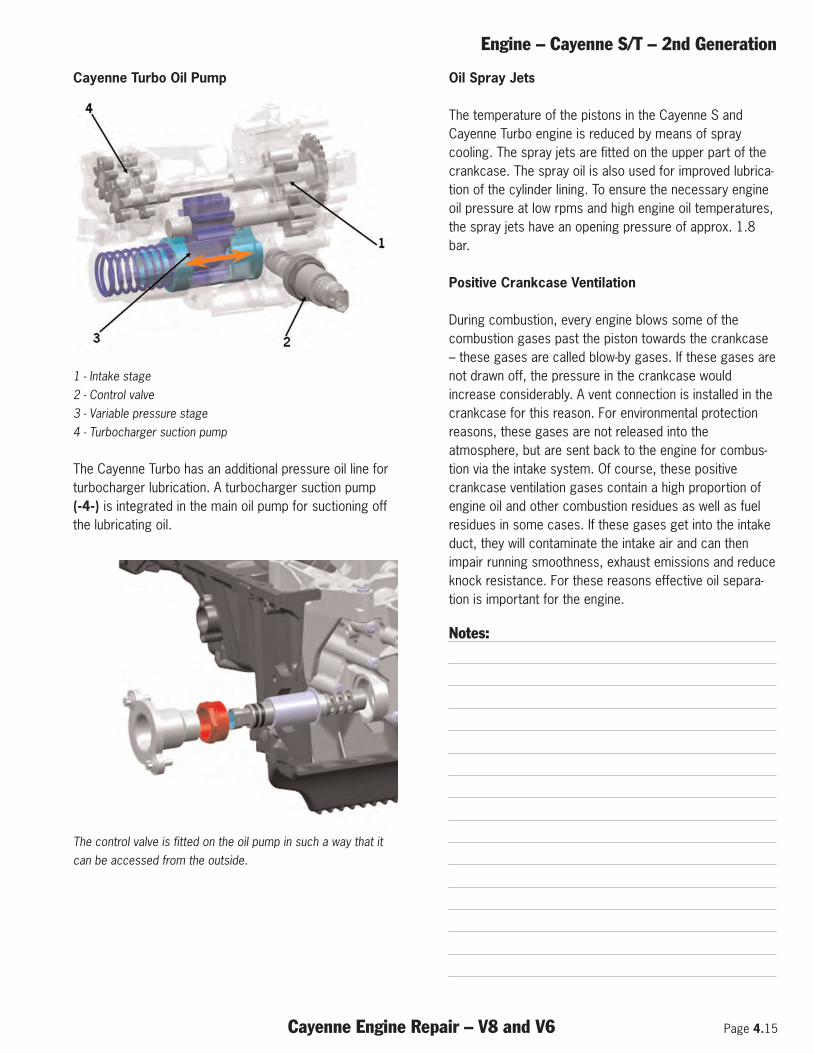
Engine – Cayenne S/T – 2nd Generation
Cayenne Engine Repair – V8 and V6 Page 4.15
Cayenne Turbo Oil Pump
1 - Intake stage 2 - Control valve 3 - Variable pressure stage 4 - Turbocharger suction pump
The Cayenne Turbo has an additional pressure oil line forturbocharger lubrication. A turbocharger suction pump(-4-) is integrated in the main oil pump for suctioning offthe lubricating oil.
The control valve is fitted on the oil pump in such a way that itcan be accessed from the outside.
Oil Spray Jets
The temperature of the pistons in the Cayenne S andCayenne Turbo engine is reduced by means of spraycooling. The spray jets are fitted on the upper part of thecrankcase. The spray oil is also used for improved lubrica-tion of the cylinder lining. To ensure the necessary engineoil pressure at low rpms and high engine oil temperatures,the spray jets have an opening pressure of approx. 1.8bar.
Positive Crankcase Ventilation
During combustion, every engine blows some of thecombustion gases past the piston towards the crankcase– these gases are called blow-by gases. If these gases arenot drawn off, the pressure in the crankcase wouldincrease considerably. A vent connection is installed in thecrankcase for this reason. For environmental protectionreasons, these gases are not released into theatmosphere, but are sent back to the engine for combus-tion via the intake system. Of course, these positivecrankcase ventilation gases contain a high proportion ofengine oil and other combustion residues as well as fuelresidues in some cases. If these gases get into the intakeduct, they will contaminate the intake air and can thenimpair running smoothness, exhaust emissions and reduceknock resistance. For these reasons effective oil separa-tion is important for the engine.
Notes:
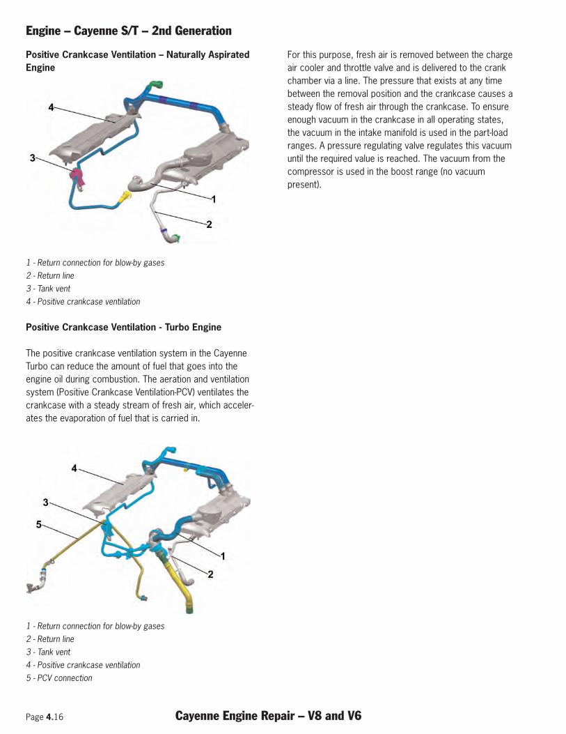
Page 4.16 Cayenne Engine Repair – V8 and V6
Engine – Cayenne S/T – 2nd Generation
Positive Crankcase Ventilation – Naturally AspiratedEngine
1 - Return connection for blow-by gases 2 - Return line 3 - Tank vent 4 - Positive crankcase ventilation
Positive Crankcase Ventilation - Turbo Engine
The positive crankcase ventilation system in the CayenneTurbo can reduce the amount of fuel that goes into theengine oil during combustion. The aeration and ventilationsystem (Positive Crankcase Ventilation-PCV) ventilates thecrankcase with a steady stream of fresh air, which acceler-ates the evaporation of fuel that is carried in.
1 - Return connection for blow-by gases 2 - Return line 3 - Tank vent 4 - Positive crankcase ventilation 5 - PCV connection
For this purpose, fresh air is removed between the chargeair cooler and throttle valve and is delivered to the crankchamber via a line. The pressure that exists at any timebetween the removal position and the crankcase causes asteady flow of fresh air through the crankcase. To ensureenough vacuum in the crankcase in all operating states,the vacuum in the intake manifold is used in the part-loadranges. A pressure regulating valve regulates this vacuumuntil the required value is reached. The vacuum from thecompressor is used in the boost range (no vacuumpresent).
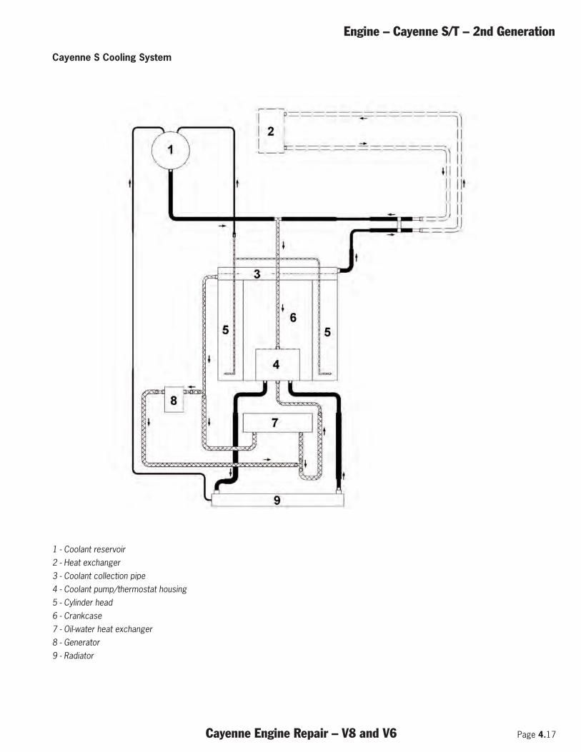
Engine – Cayenne S/T – 2nd Generation
Cayenne Engine Repair – V8 and V6 Page 4.17
Cayenne S Cooling System
1 - Coolant reservoir 2 - Heat exchanger 3 - Coolant collection pipe 4 - Coolant pump/thermostat housing 5 - Cylinder head 6 - Crankcase 7 - Oil-water heat exchanger 8 - Generator 9 - Radiator
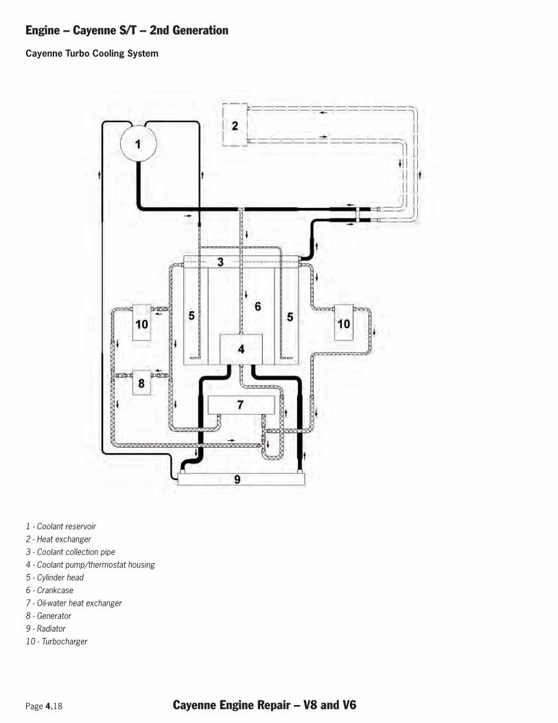
Page 4.18 Cayenne Engine Repair – V8 and V6
Engine – Cayenne S/T – 2nd Generation
Cayenne Turbo Cooling System
1 - Coolant reservoir 2 - Heat exchanger 3 - Coolant collection pipe 4 - Coolant pump/thermostat housing 5 - Cylinder head 6 - Crankcase 7 - Oil-water heat exchanger 8 - Generator 9 - Radiator 10 - Turbocharger
Engine – Cayenne (V6) – 2nd Generation
Cayenne Engine Repair – V8 and V6 Page 5.1
Subject Page
General . . . . . . . . . . . . . . . . . . . . . . . . . . . . . . . . . . . . . . . . . . . . . . . . . . . . . . . . . . . . . . . . .3
Cayenne Engine Data . . . . . . . . . . . . . . . . . . . . . . . . . . . . . . . . . . . . . . . . . . . . . . . . . . . . . . . .3
Crankcase . . . . . . . . . . . . . . . . . . . . . . . . . . . . . . . . . . . . . . . . . . . . . . . . . . . . . . . . . . . . . . .3
Pistons . . . . . . . . . . . . . . . . . . . . . . . . . . . . . . . . . . . . . . . . . . . . . . . . . . . . . . . . . . . . . . . . . .4
Connecting Rods . . . . . . . . . . . . . . . . . . . . . . . . . . . . . . . . . . . . . . . . . . . . . . . . . . . . . . . . . . .4
Belt Drive . . . . . . . . . . . . . . . . . . . . . . . . . . . . . . . . . . . . . . . . . . . . . . . . . . . . . . . . . . . . . . . .5
V-Angle . . . . . . . . . . . . . . . . . . . . . . . . . . . . . . . . . . . . . . . . . . . . . . . . . . . . . . . . . . . . . . . . . .6
Cylinder Head . . . . . . . . . . . . . . . . . . . . . . . . . . . . . . . . . . . . . . . . . . . . . . . . . . . . . . . . . . . . .6
Camshaft Adjustment . . . . . . . . . . . . . . . . . . . . . . . . . . . . . . . . . . . . . . . . . . . . . . . . . . . . . . . .6
Exhaust Gas Recirculation . . . . . . . . . . . . . . . . . . . . . . . . . . . . . . . . . . . . . . . . . . . . . . . . . . . . .8
Positive Crankcase Ventilation . . . . . . . . . . . . . . . . . . . . . . . . . . . . . . . . . . . . . . . . . . . . . . . . . .9
Cyclone Oil Separator . . . . . . . . . . . . . . . . . . . . . . . . . . . . . . . . . . . . . . . . . . . . . . . . . . . . . .10
Oil Lubrication System . . . . . . . . . . . . . . . . . . . . . . . . . . . . . . . . . . . . . . . . . . . . . . . . . . . . . .11
Cooling System . . . . . . . . . . . . . . . . . . . . . . . . . . . . . . . . . . . . . . . . . . . . . . . . . . . . . . . . . .13
Page 5.2 Cayenne Engine Repair – V8 and V6
Engine – Cayenne (V6) – 2nd Generation
Notes:
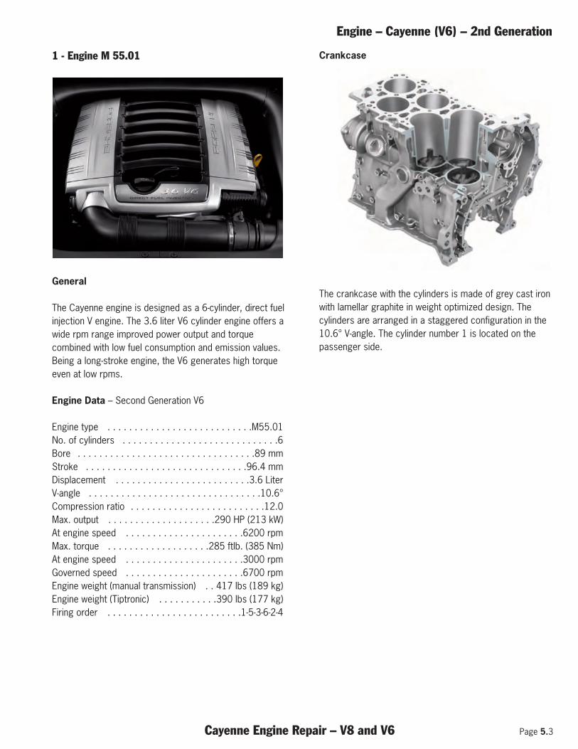
Engine – Cayenne (V6) – 2nd Generation
Cayenne Engine Repair – V8 and V6 Page 5.3
1 - Engine M 55.01
General
The Cayenne engine is designed as a 6-cylinder, direct fuelinjection V engine. The 3.6 liter V6 cylinder engine offers awide rpm range improved power output and torquecombined with low fuel consumption and emission values.Being a long-stroke engine, the V6 generates high torqueeven at low rpms.
Engine Data – Second Generation V6
Engine type . . . . . . . . . . . . . . . . . . . . . . . . . . .M55.01 No. of cylinders . . . . . . . . . . . . . . . . . . . . . . . . . . . . .6Bore . . . . . . . . . . . . . . . . . . . . . . . . . . . . . . . . .89 mm Stroke . . . . . . . . . . . . . . . . . . . . . . . . . . . . . .96.4 mm Displacement . . . . . . . . . . . . . . . . . . . . . . . . .3.6 Liter V-angle . . . . . . . . . . . . . . . . . . . . . . . . . . . . . . . .10.6°Compression ratio . . . . . . . . . . . . . . . . . . . . . . . . .12.0 Max. output . . . . . . . . . . . . . . . . . . . .290 HP (213 kW) At engine speed . . . . . . . . . . . . . . . . . . . . . .6200 rpm Max. torque . . . . . . . . . . . . . . . . . . .285 ftlb. (385 Nm) At engine speed . . . . . . . . . . . . . . . . . . . . . .3000 rpm Governed speed . . . . . . . . . . . . . . . . . . . . . .6700 rpm Engine weight (manual transmission) . . 417 lbs (189 kg) Engine weight (Tiptronic) . . . . . . . . . . .390 lbs (177 kg) Firing order . . . . . . . . . . . . . . . . . . . . . . . . .1-5-3-6-2-4
Crankcase
The crankcase with the cylinders is made of grey cast ironwith lamellar graphite in weight optimized design. Thecylinders are arranged in a staggered configuration in the10.6° V-angle. The cylinder number 1 is located on thepassenger side.
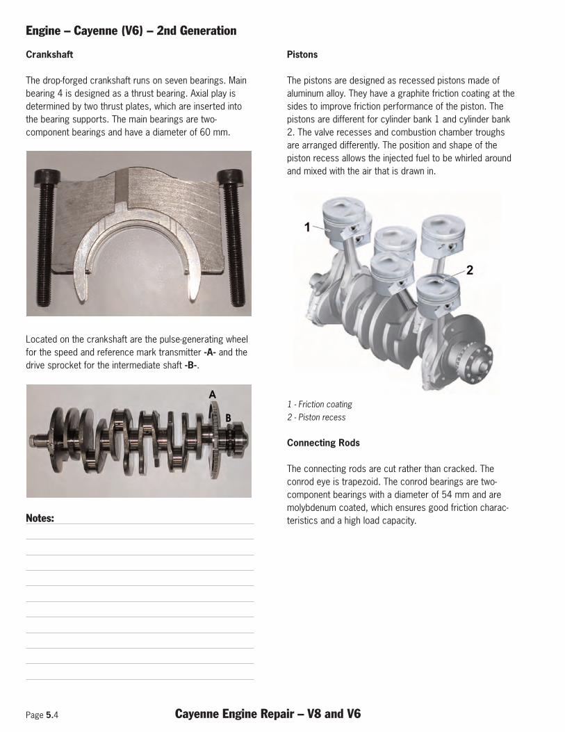
Page 5.4 Cayenne Engine Repair – V8 and V6
Engine – Cayenne (V6) – 2nd Generation
Crankshaft
The drop-forged crankshaft runs on seven bearings. Mainbearing 4 is designed as a thrust bearing. Axial play isdetermined by two thrust plates, which are inserted intothe bearing supports. The main bearings are two-component bearings and have a diameter of 60 mm.
Located on the crankshaft are the pulse-generating wheelfor the speed and reference mark transmitter -A- and thedrive sprocket for the intermediate shaft -B-.
Notes:
Pistons
The pistons are designed as recessed pistons made ofaluminum alloy. They have a graphite friction coating at thesides to improve friction performance of the piston. Thepistons are different for cylinder bank 1 and cylinder bank2. The valve recesses and combustion chamber troughsare arranged differently. The position and shape of thepiston recess allows the injected fuel to be whirled aroundand mixed with the air that is drawn in.
1 - Friction coating 2 - Piston recess
Connecting Rods
The connecting rods are cut rather than cracked. Theconrod eye is trapezoid. The conrod bearings are two-component bearings with a diameter of 54 mm and aremolybdenum coated, which ensures good friction charac-teristics and a high load capacity.
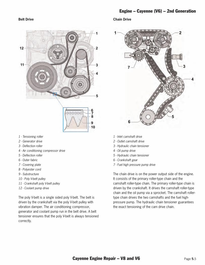
Engine – Cayenne (V6) – 2nd Generation
Cayenne Engine Repair – V8 and V6 Page 5.5
Belt Drive
1 - Tensioning roller 2 - Generator drive 3 - Deflection roller 4 - Air conditioning compressor drive 5 - Deflection roller 6 - Outer fabric 7 - Covering plate 8 - Polyester cord 9 - Substructure 10 - Poly V-belt pulley 11 - Crankshaft poly V-belt pulley 12 - Coolant pump drive
The poly V-belt is a single sided poly V-belt. The belt isdriven by the crankshaft via the poly V-belt pulley withvibration damper. The air conditioning compressor,generator and coolant pump run in the belt drive. A belttensioner ensures that the poly V-belt is always tensionedcorrectly.
Chain Drive
1 - Inlet camshaft drive 2 - Outlet camshaft drive 3 - Hydraulic chain tensioner 4 - Oil pump drive 5 - Hydraulic chain tensioner 6 - Crankshaft gear 7 - Fuel high pressure pump drive
The chain drive is on the power output side of the engine.It consists of the primary roller-type chain and thecamshaft roller-type chain. The primary roller-type chain isdriven by the crankshaft. It drives the camshaft roller-typechain and the oil pump via a sprocket. The camshaft roller-type chain drives the two camshafts and the fuel high-pressure pump. The hydraulic chain tensioner guaranteesthe exact tensioning of the cam drive chain.
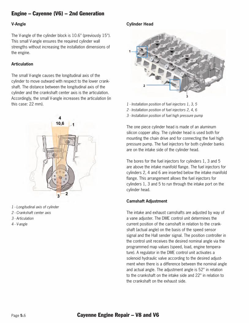
Page 5.6 Cayenne Engine Repair – V8 and V6
Engine – Cayenne (V6) – 2nd Generation
V-Angle
The V-angle of the cylinder block is 10.6° (previously 15°).This small V-angle ensures the required cylinder wallstrengths without increasing the installation dimensions ofthe engine.
Articulation
The small V-angle causes the longitudinal axis of thecylinder to move outward with respect to the lower crank-shaft. The distance between the longitudinal axis of thecylinder and the crankshaft center axis is the articulation.Accordingly, the small V-angle increases the articulation (inthis case: 22 mm).
1 - Longitudinal axis of cylinder 2 - Crankshaft center axis 3 - Articulation 4 - V-angle
Cylinder Head
1 - Installation position of fuel injectors 1, 3, 5 2 - Installation position of fuel injectors 2, 4, 6 3 - Installation position of fuel high pressure pump
The one piece cylinder head is made of an aluminumsilicon copper alloy. The cylinder head is used both formounting the chain drive and for connecting the fuel highpressure pump. The fuel injectors for both cylinder banksare on the intake side of the cylinder head.
The bores for the fuel injectors for cylinders 1, 3 and 5are above the intake manifold flange. The fuel injectors forcylinders 2, 4 and 6 are inserted below the intake manifoldflange. This arrangement allows the fuel injectors forcylinders 1, 3 and 5 to run through the intake port on thecylinder head.
Camshaft Adjustment
The intake and exhaust camshafts are adjusted by way ofa vane adjuster. The DME control unit determines thecurrent position of the camshaft in relation to the crank-shaft (actual angle) on the basis of the speed sensorsignal and the Hall sender signal. The position controller inthe control unit receives the desired nominal angle via theprogrammed map values (speed, load, engine tempera-ture). A regulator in the DME control unit activates asolenoid hydraulic valve according to the desired adjust-ment when there is a difference between the nominal angleand actual angle. The adjustment angle is 52° in relationto the crankshaft on the intake side and 22° in relation tothe crankshaft on the exhaust side.
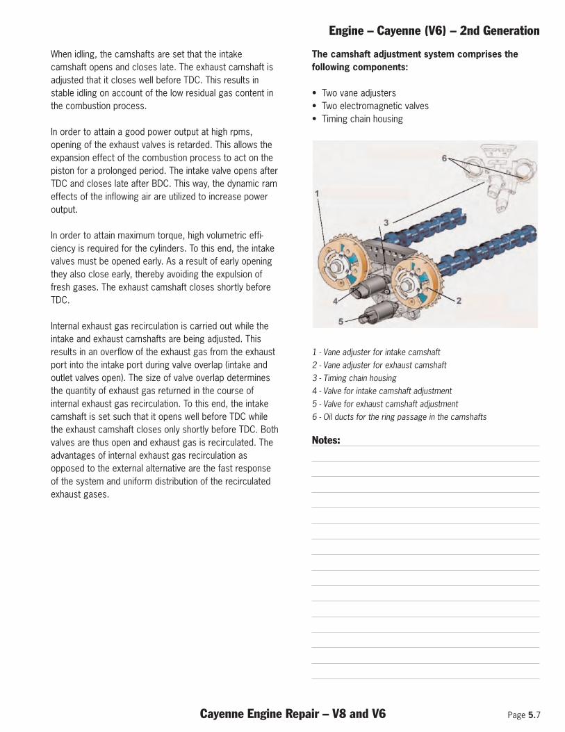
Engine – Cayenne (V6) – 2nd Generation
Cayenne Engine Repair – V8 and V6 Page 5.7
When idling, the camshafts are set that the intakecamshaft opens and closes late. The exhaust camshaft isadjusted that it closes well before TDC. This results instable idling on account of the low residual gas content inthe combustion process.
In order to attain a good power output at high rpms,opening of the exhaust valves is retarded. This allows theexpansion effect of the combustion process to act on thepiston for a prolonged period. The intake valve opens afterTDC and closes late after BDC. This way, the dynamic rameffects of the inflowing air are utilized to increase poweroutput.
In order to attain maximum torque, high volumetric effi-ciency is required for the cylinders. To this end, the intakevalves must be opened early. As a result of early openingthey also close early, thereby avoiding the expulsion offresh gases. The exhaust camshaft closes shortly beforeTDC.
Internal exhaust gas recirculation is carried out while theintake and exhaust camshafts are being adjusted. Thisresults in an overflow of the exhaust gas from the exhaustport into the intake port during valve overlap (intake andoutlet valves open). The size of valve overlap determinesthe quantity of exhaust gas returned in the course ofinternal exhaust gas recirculation. To this end, the intakecamshaft is set such that it opens well before TDC whilethe exhaust camshaft closes only shortly before TDC. Bothvalves are thus open and exhaust gas is recirculated. Theadvantages of internal exhaust gas recirculation asopposed to the external alternative are the fast responseof the system and uniform distribution of the recirculatedexhaust gases.
The camshaft adjustment system comprises thefollowing components:
• Two vane adjusters• Two electromagnetic valves• Timing chain housing
1 - Vane adjuster for intake camshaft 2 - Vane adjuster for exhaust camshaft 3 - Timing chain housing 4 - Valve for intake camshaft adjustment 5 - Valve for exhaust camshaft adjustment 6 - Oil ducts for the ring passage in the camshafts
Notes:
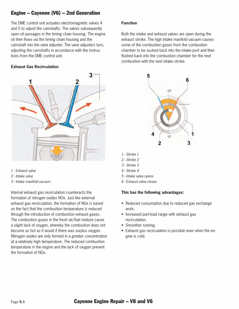
Page 5.8 Cayenne Engine Repair – V8 and V6
Engine – Cayenne (V6) – 2nd Generation
The DME control unit actuates electromagnetic valves 4and 5 to adjust the camshafts. The valves subsequentlyopen oil passages in the timing chain housing. The engineoil then flows via the timing chain housing and thecamshaft into the vane adjuster. The vane adjusters turn,adjusting the camshafts in accordance with the instruc-tions from the DME control unit.
Exhaust Gas Recirculation
1 - Exhaust valve 2 - Intake valve 3 - Intake manifold vacuum
Internal exhaust gas recirculation counteracts theformation of nitrogen oxides NOx. Just like externalexhaust gas recirculation, the formation of NOx is basedon the fact that the combustion temperature is reducedthrough the introduction of combustion exhaust gases.The combustion gases in the fresh air/fuel mixture causea slight lack of oxygen, whereby the combustion does notbecome as hot as it would if there was surplus oxygen.Nitrogen oxides are only formed in a greater concentrationat a relatively high temperature. The reduced combustiontemperature in the engine and the lack of oxygen preventthe formation of NOx.
Function
Both the intake and exhaust valves are open during theexhaust stroke. The high intake manifold vacuum causessome of the combustion gases from the combustionchamber to be sucked back into the intake port and thenflushed back into the combustion chamber for the nextcombustion with the next intake stroke.
1 - Stroke 1 2 - Stroke 2 3 - Stroke 3 4 - Stroke 4 5 - Intake valve opens 6 - Exhaust valve closes
This has the following advantages:
• Reduced consumption due to reduced gas exchangework.
• Increased part-load range with exhaust gasrecirculation.
• Smoother running. • Exhaust gas recirculation is possible even when the en-
gine is cold.
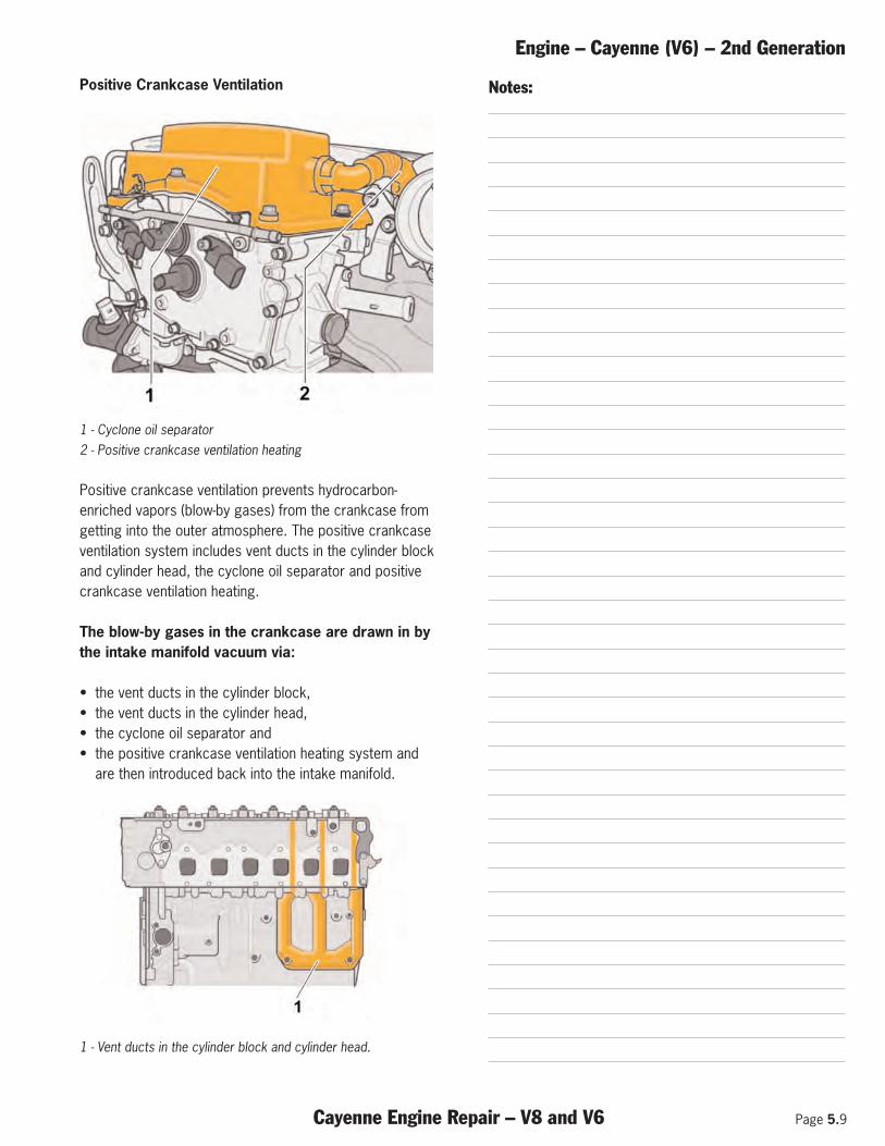
Engine – Cayenne (V6) – 2nd Generation
Cayenne Engine Repair – V8 and V6 Page 5.9
Positive Crankcase Ventilation
1 - Cyclone oil separator 2 - Positive crankcase ventilation heating
Positive crankcase ventilation prevents hydrocarbon-enriched vapors (blow-by gases) from the crankcase fromgetting into the outer atmosphere. The positive crankcaseventilation system includes vent ducts in the cylinder blockand cylinder head, the cyclone oil separator and positivecrankcase ventilation heating.
The blow-by gases in the crankcase are drawn in bythe intake manifold vacuum via:
• the vent ducts in the cylinder block,• the vent ducts in the cylinder head,• the cyclone oil separator and • the positive crankcase ventilation heating system and
are then introduced back into the intake manifold.
1 - Vent ducts in the cylinder block and cylinder head.
Notes:
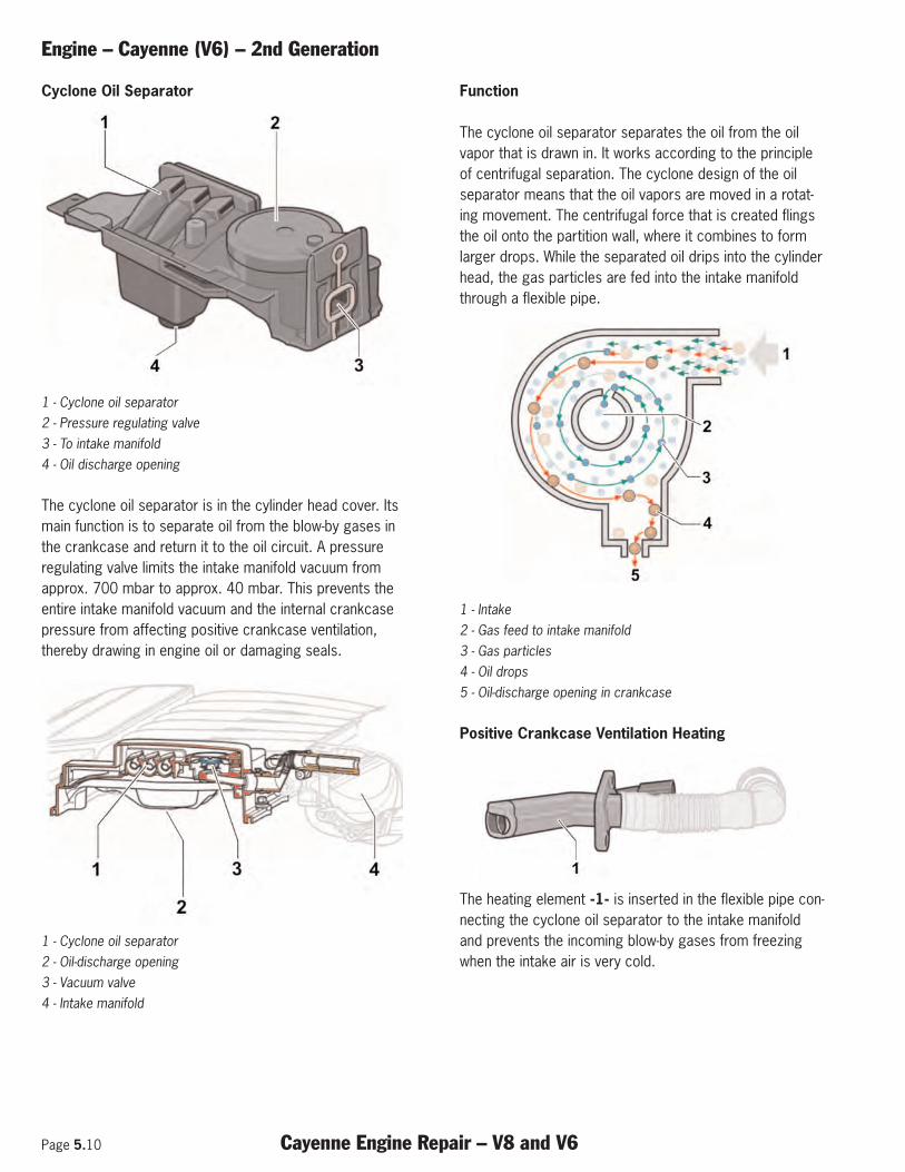
Page 5.10 Cayenne Engine Repair – V8 and V6
Engine – Cayenne (V6) – 2nd Generation
Cyclone Oil Separator
1 - Cyclone oil separator 2 - Pressure regulating valve3 - To intake manifold 4 - Oil discharge opening
The cyclone oil separator is in the cylinder head cover. Itsmain function is to separate oil from the blow-by gases inthe crankcase and return it to the oil circuit. A pressureregulating valve limits the intake manifold vacuum from approx. 700 mbar to approx. 40 mbar. This prevents theentire intake manifold vacuum and the internal crankcasepressure from affecting positive crankcase ventilation,thereby drawing in engine oil or damaging seals.
1 - Cyclone oil separator 2 - Oil-discharge opening 3 - Vacuum valve 4 - Intake manifold
Function
The cyclone oil separator separates the oil from the oilvapor that is drawn in. It works according to the principleof centrifugal separation. The cyclone design of the oilseparator means that the oil vapors are moved in a rotat-ing movement. The centrifugal force that is created flingsthe oil onto the partition wall, where it combines to formlarger drops. While the separated oil drips into the cylinderhead, the gas particles are fed into the intake manifoldthrough a flexible pipe.
1 - Intake 2 - Gas feed to intake manifold 3 - Gas particles 4 - Oil drops 5 - Oil-discharge opening in crankcase
Positive Crankcase Ventilation Heating
The heating element -1- is inserted in the flexible pipe con-necting the cyclone oil separator to the intake manifoldand prevents the incoming blow-by gases from freezingwhen the intake air is very cold.
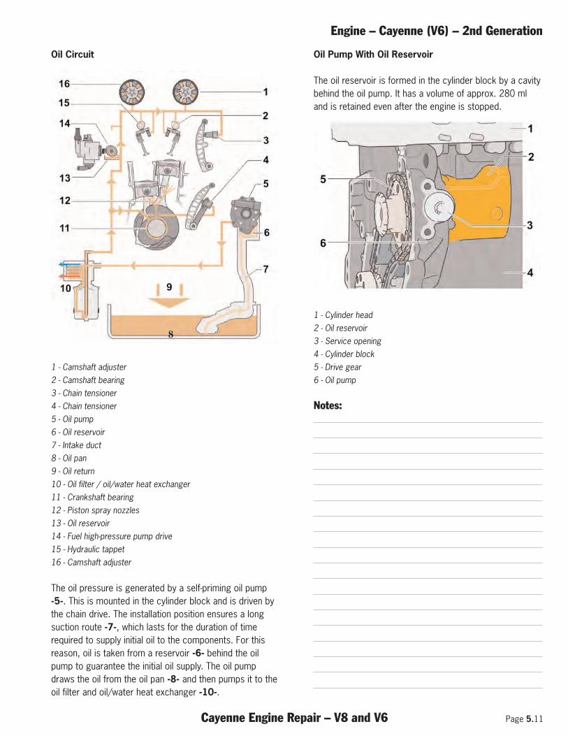
Engine – Cayenne (V6) – 2nd Generation
Cayenne Engine Repair – V8 and V6 Page 5.11
Oil Circuit
1 - Camshaft adjuster 2 - Camshaft bearing 3 - Chain tensioner 4 - Chain tensioner 5 - Oil pump 6 - Oil reservoir 7 - Intake duct 8 - Oil pan 9 - Oil return 10 - Oil filter / oil/water heat exchanger 11 - Crankshaft bearing 12 - Piston spray nozzles 13 - Oil reservoir 14 - Fuel high-pressure pump drive 15 - Hydraulic tappet 16 - Camshaft adjuster
The oil pressure is generated by a self-priming oil pump-5-. This is mounted in the cylinder block and is driven bythe chain drive. The installation position ensures a longsuction route -7-, which lasts for the duration of timerequired to supply initial oil to the components. For thisreason, oil is taken from a reservoir -6- behind the oilpump to guarantee the initial oil supply. The oil pumpdraws the oil from the oil pan -8- and then pumps it to theoil filter and oil/water heat exchanger -10-.
Oil Pump With Oil Reservoir
The oil reservoir is formed in the cylinder block by a cavitybehind the oil pump. It has a volume of approx. 280 mland is retained even after the engine is stopped.
1 - Cylinder head 2 - Oil reservoir 3 - Service opening 4 - Cylinder block 5 - Drive gear 6 - Oil pump
Notes:
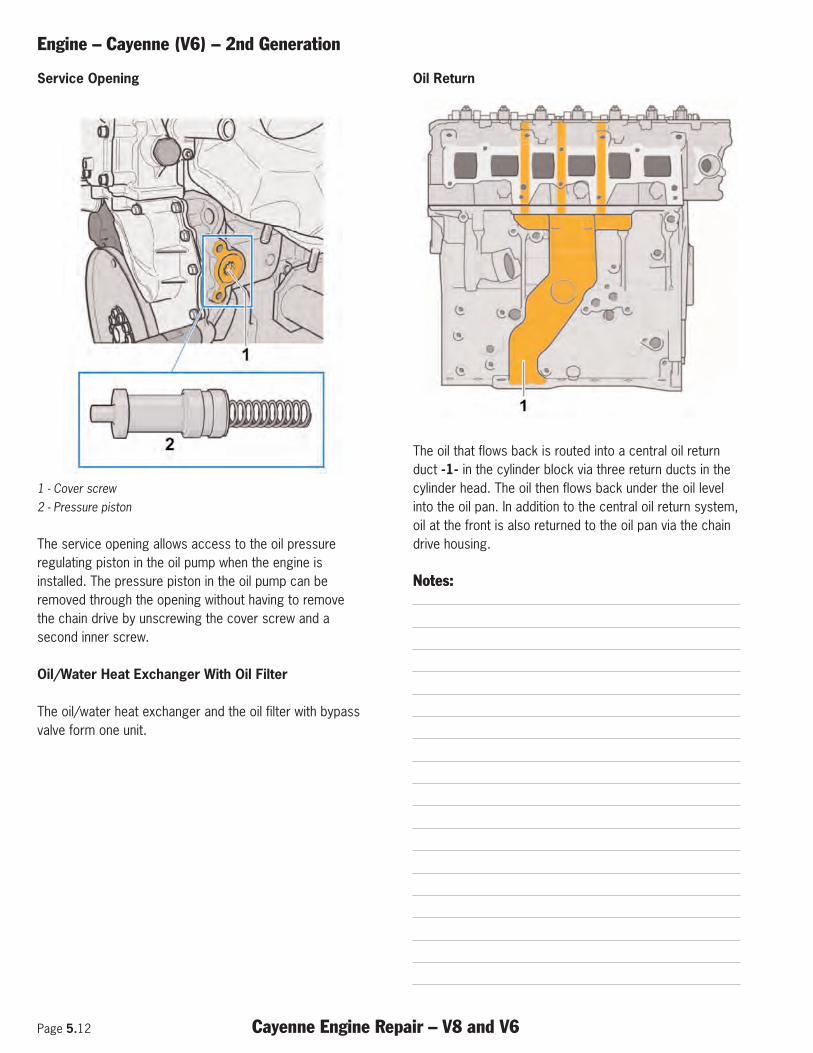
Page 5.12 Cayenne Engine Repair – V8 and V6
Engine – Cayenne (V6) – 2nd Generation
Service Opening
1 - Cover screw 2 - Pressure piston
The service opening allows access to the oil pressureregulating piston in the oil pump when the engine isinstalled. The pressure piston in the oil pump can beremoved through the opening without having to removethe chain drive by unscrewing the cover screw and asecond inner screw.
Oil/Water Heat Exchanger With Oil Filter
The oil/water heat exchanger and the oil filter with bypassvalve form one unit.
Oil Return
The oil that flows back is routed into a central oil returnduct -1- in the cylinder block via three return ducts in thecylinder head. The oil then flows back under the oil levelinto the oil pan. In addition to the central oil return system,oil at the front is also returned to the oil pan via the chaindrive housing.
Notes:
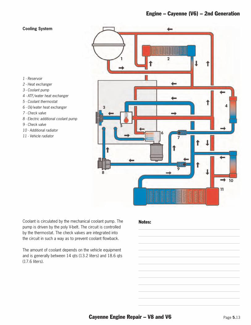
Engine – Cayenne (V6) – 2nd Generation
Cayenne Engine Repair – V8 and V6 Page 5.13
Coolant is circulated by the mechanical coolant pump. Thepump is driven by the poly V-belt. The circuit is controlledby the thermostat. The check valves are integrated intothe circuit in such a way as to prevent coolant flowback.
The amount of coolant depends on the vehicle equipmentand is generally between 14 qts (13.2 liters) and 18.6 qts(17.6 liters).
Notes:
Cooling System
1 - Reservoir 2 - Heat exchanger 3 - Coolant pump 4 - ATF/water heat exchanger 5 - Coolant thermostat 6 - Oil/water heat exchanger 7 - Check valve 8 - Electric additional coolant pump 9 - Check valve 10 - Additional radiator 11 - Vehicle radiator

Page 5.14 Cayenne Engine Repair – V8 and V6
Engine – Cayenne (V6) – 2nd Generation
Notes:
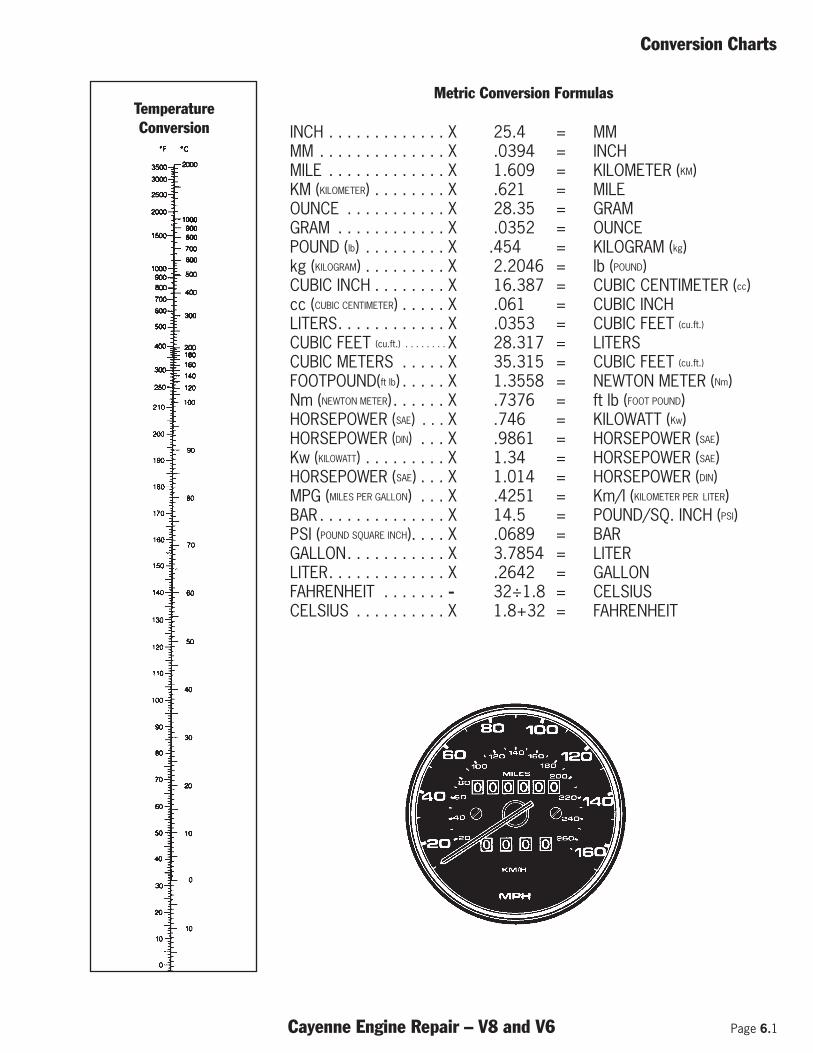
Conversion Charts
Cayenne Engine Repair – V8 and V6 Page 6.1
Metric Conversion Formulas
INCH . . . . . . . . . . . . . X 25.4 = MMMM . . . . . . . . . . . . . . X .0394 = INCHMILE . . . . . . . . . . . . . X 1.609 = KILOMETER (KM)KM (KILOMETER) . . . . . . . . X .621 = MILEOUNCE . . . . . . . . . . . X 28.35 = GRAMGRAM . . . . . . . . . . . . X .0352 = OUNCEPOUND (lb) . . . . . . . . . X .454 = KILOGRAM (kg)kg (KILOGRAM) . . . . . . . . . X 2.2046 = lb (POUND)CUBIC INCH . . . . . . . . X 16.387 = CUBIC CENTIMETER (cc)cc (CUBIC CENTIMETER) . . . . . X .061 = CUBIC INCHLITERS. . . . . . . . . . . . X .0353 = CUBIC FEET (cu.ft.)
CUBIC FEET (cu.ft.) . . . . . . . . X 28.317 = LITERSCUBIC METERS . . . . . X 35.315 = CUBIC FEET (cu.ft.)
FOOTPOUND(ft lb) . . . . . X 1.3558 = NEWTON METER (Nm)Nm (NEWTON METER) . . . . . . X .7376 = ft lb (FOOT POUND)HORSEPOWER (SAE) . . . X .746 = KILOWATT (Kw)HORSEPOWER (DIN) . . . X .9861 = HORSEPOWER (SAE)Kw (KILOWATT) . . . . . . . . . X 1.34 = HORSEPOWER (SAE)HORSEPOWER (SAE) . . . X 1.014 = HORSEPOWER (DIN)MPG (MILES PER GALLON) . . . X .4251 = Km/l (KILOMETER PER LITER)BAR . . . . . . . . . . . . . . X 14.5 = POUND/SQ. INCH (PSI)PSI (POUND SQUARE INCH). . . . X .0689 = BARGALLON. . . . . . . . . . . X 3.7854 = LITERLITER. . . . . . . . . . . . . X .2642 = GALLONFAHRENHEIT . . . . . . . - 32÷1.8 = CELSIUSCELSIUS . . . . . . . . . . X 1.8+32 = FAHRENHEIT
TemperatureConversion
Page 6.2 Cayenne Engine Repair – V8 and V6
Conversion Charts
Notes:

Part Number - PNA P10 C03