Embed Size (px)
DESCRIPTION
Ageing studies of resistive Micromegas detectors for the HL-LHC. J. Galan CEA Saclay f or the MAMMA collaboration. J. Galan VCI 2013 12/Feb/2013. The New Small Wheel upgrade for the HL-LHC. NSW. ATLAS. - PowerPoint PPT Presentation
Citation preview
Ageing studies of resistive Micromegas detectors for the HL-LHC
J. Galan VCI 2013 12/Feb/2013
J. GalanCEA Saclay
for the MAMMA collaboration
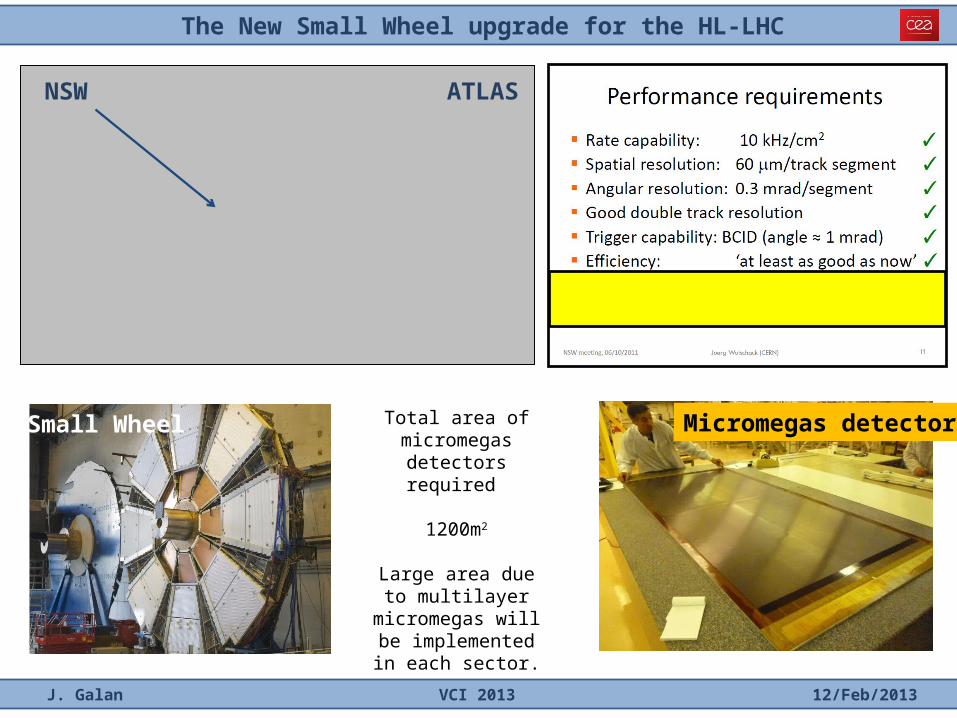
The New Small Wheel upgrade for the HL-LHC
J. Galan VCI 2013 12/Feb/2013
ATLASNSW
Micromegas detectorTotal area of micromegas detectors
required
1200m2
Large area due to multilayer micromegas will be implemented in
each sector.
Small Wheel
Micromegas detectors for the new small wheel
J. Galan VCI 2013 12/Feb/2013
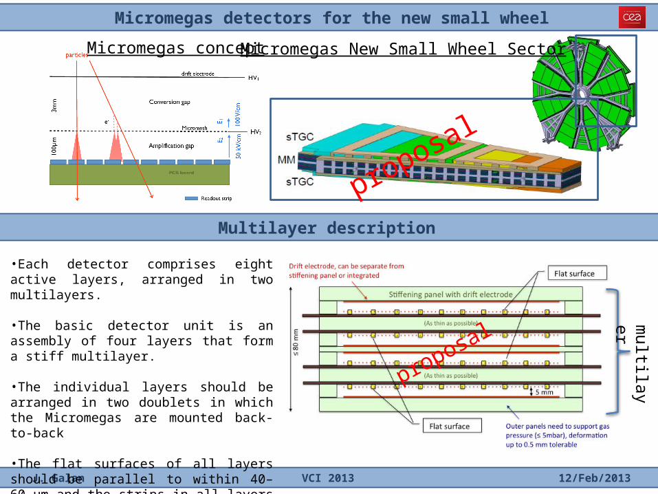
Multilayer description
multilayer
•Each detector comprises eight active layers, arranged in two multilayers.
•The basic detector unit is an assembly of four layers that form a stiff multilayer.
•The individual layers should be arranged in two doublets in which the Micromegas are mounted back-to-back
•The flat surfaces of all layers should be parallel to within 40–60 µm and the strips in all layers must be parallel with the same precision.
Micromegas concept Micromegas New Small Wheel Sector
proposal
proposal
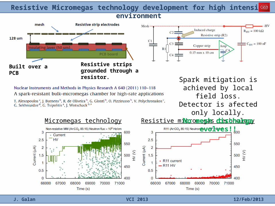
Resistive Micromegas technology development for high intensity environment
J. Galan VCI 2013 12/Feb/2013
Micromegas technology Resistive micromegas technology
Resistive strips grounded through a resistor.
Built over a PCB
Spark mitigation is achieved by local field loss.
Detector is afected only locally.No mesh discharge evolves!!
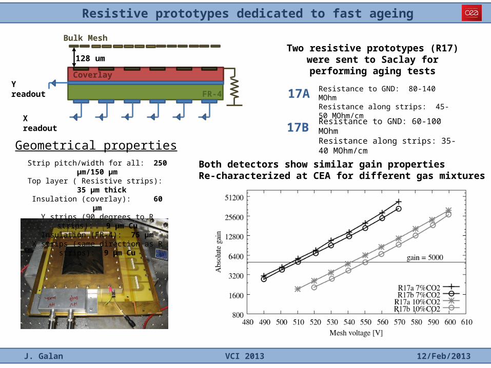
Resistive prototypes dedicated to fast ageing
J. Galan VCI 2013 12/Feb/2013
Strip pitch/width for all: 250 µm/150 µmTop layer ( Resistive strips): 35 µm thick
Insulation (coverlay): 60 µmY strips (90 degrees to R strips): 9 µm Cu
Insulation (FR-4): 75 µmX strips (same direction as R strips): 9 µm Cu
Geometrical properties
Y readout
X readout
Coverlay
FR-4
128 um
Bulk MeshTwo resistive prototypes (R17) were sent to
Saclay for performing aging tests
17A Resistance to GND: 80-140 MOhmResistance along strips: 45-50 MOhm/cm
Resistance to GND: 60-100 MOhmResistance along strips: 35-40 MOhm/cm17B
Both detectors show similar gain propertiesRe-characterized at CEA for different gas mixtures
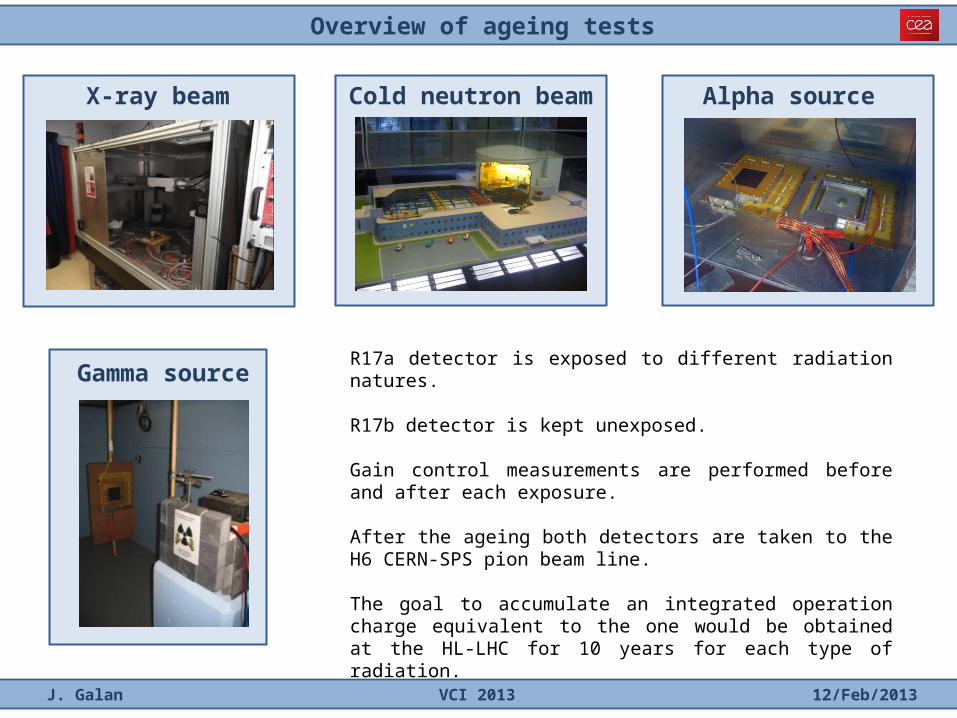
Overview of ageing tests
J. Galan VCI 2013 12/Feb/2013
X-ray beam Cold neutron beam
Gamma source
Alpha source
R17a detector is exposed to different radiation natures.
R17b detector is kept unexposed.
Gain control measurements are performed before and after each exposure.
After the ageing both detectors are taken to the H6 CERN-SPS pion beam line.
The goal to accumulate an integrated operation charge equivalent to the one would be obtained at the HL-LHC for 10 years for each type of radiation.
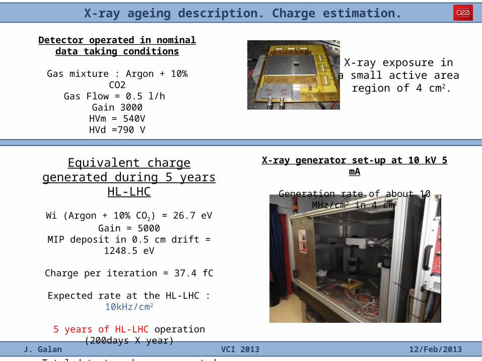
X-ray ageing description. Charge estimation.
J. Galan VCI 2013 12/Feb/2013
Equivalent charge generated during 5 years HL-LHC
Wi (Argon + 10% CO2) = 26.7 eVGain = 5000
MIP deposit in 0.5 cm drift = 1248.5 eV
Charge per iteration = 37.4 fC
Expected rate at the HL-LHC : 10kHz/cm2
5 years of HL-LHC operation (200days X year)
Total detector charge generated during HL-LHC operation is estimated to be 32.5 mC/cm2
Detector operated in nominal data taking conditions
Gas mixture : Argon + 10% CO2Gas Flow = 0.5 l/h
Gain 3000HVm = 540VHVd =790 V
X-ray exposure in a small active area
region of 4 cm2.
X-ray generator set-up at 10 kV 5 mA
Generation rate of about 10 MHz/cm2 in 4 cm2
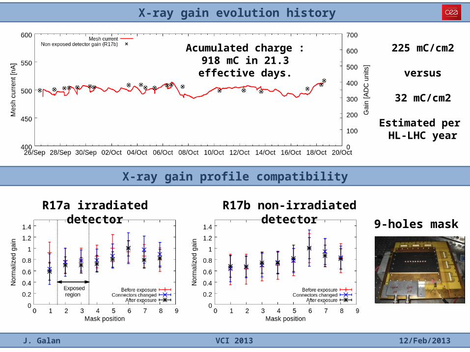
X-ray gain evolution history
J. Galan VCI 2013 12/Feb/2013
X-ray gain profile compatibility
R17a irradiated detector R17b non-irradiated detector
Acumulated charge : 918 mC in 21.3 effective days.
225 mC/cm2
versus
32 mC/cm2
Estimated per HL-LHC year
9-holes mask
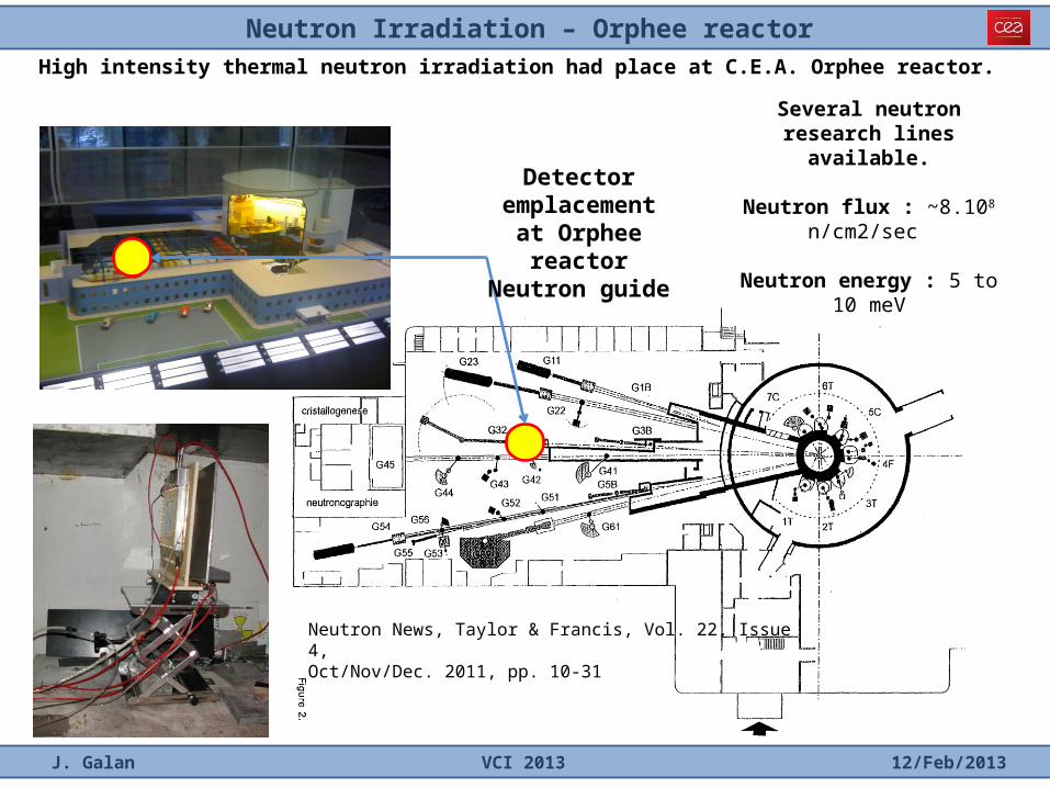
Neutron Irradiation – Orphee reactor
J. Galan VCI 2013 12/Feb/2013
Detector emplacement
at Orphee reactorNeutron guide
High intensity thermal neutron irradiation had place at C.E.A. Orphee reactor.
Several neutron research lines available.
Neutron flux : ~8.108 n/cm2/sec
Neutron energy : 5 to 10 meV
Neutron News, Taylor & Francis, Vol. 22, Issue 4,Oct/Nov/Dec. 2011, pp. 10-31
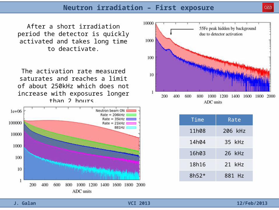
Neutron irradiation – First exposure
J. Galan VCI 2013 12/Feb/2013
Time Rate
11h08 206 kHz
14h04 35 kHz
16h03 26 kHz
18h16 21 kHz
8h52* 881 Hz
After a short irradiation period the detector is quickly activated and takes long time to
deactivate.
The activation rate measured saturates and reaches a limit of about 250kHz which does not increase with exposures longer than 2
hours.
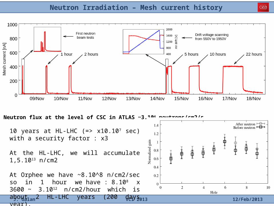
Neutron Irradiation – Mesh current history
J. Galan VCI 2013 12/Feb/2013
Neutron flux at the level of CSC in ATLAS ~3.104 neutrons/cm2/s
10 years at HL-LHC (=> x10.107 sec) with a security factor : x3 At the HL-LHC, we will accumulate 1,5.1013 n/cm2 At Orphee we have ~8.10^8 n/cm2/sec so in 1 hour we have : 8.108 x 3600 ~ 3.1012 n/cm2/hour which is about 2 HL-LHC years (200 days year).
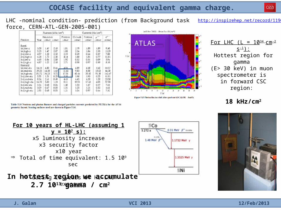
COCASE facility and equivalent gamma charge.
J. Galan VCI 2013 12/Feb/2013
For 10 years of HL-LHC (assuming 1 y = 107 s):x5 luminosity increase
x3 security factorx10 year
Þ Total of time equivalent: 1.5 109 sec
Þ during 10 years of HL-LHC exposure
LHC -nominal condition- prediction (from Background task force, CERN-ATL-GEN-2005-001)
In hottest region we accumulate2.7 1013 gamma / cm2
For LHC (L = 1034 cm-2 s-1):Hottest region for gamma
(E> 30 keV) in muon spectrometer is
in forward CSC region:
18 kHz/cm2
http://inspirehep.net/record/1196420
ATLAS
Gamma irradiation - Mesh current history and control measurements
J. Galan VCI 2013 12/Feb/2013
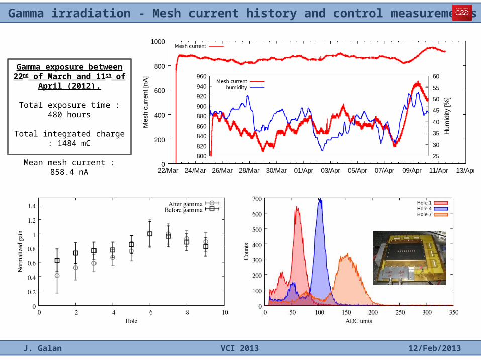
Gamma exposure between 22nd of March and 11th of April (2012).
Total exposure time : 480 hours
Total integrated charge : 1484 mC
Mean mesh current : 858.4 nA
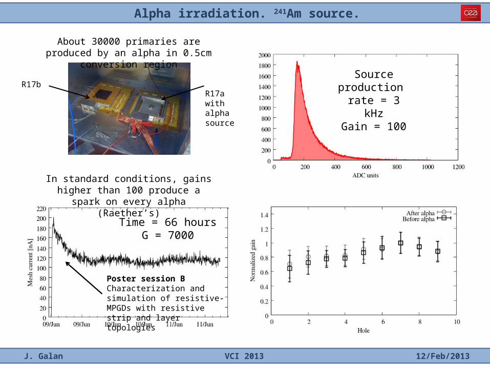
Alpha irradiation. 241Am source.
J. Galan VCI 2013 12/Feb/2013
Time = 66 hoursG = 7000
Source production rate = 3 kHzGain = 100
About 30000 primaries are produced by an alpha in 0.5cm conversion region
In standard conditions, gains higher than 100 produce a spark on every alpha
(Raether’s)
R17a with alpha source
R17b
Poster session BCharacterization and simulation of resistive-MPGDs with resistive strip and layer topologies
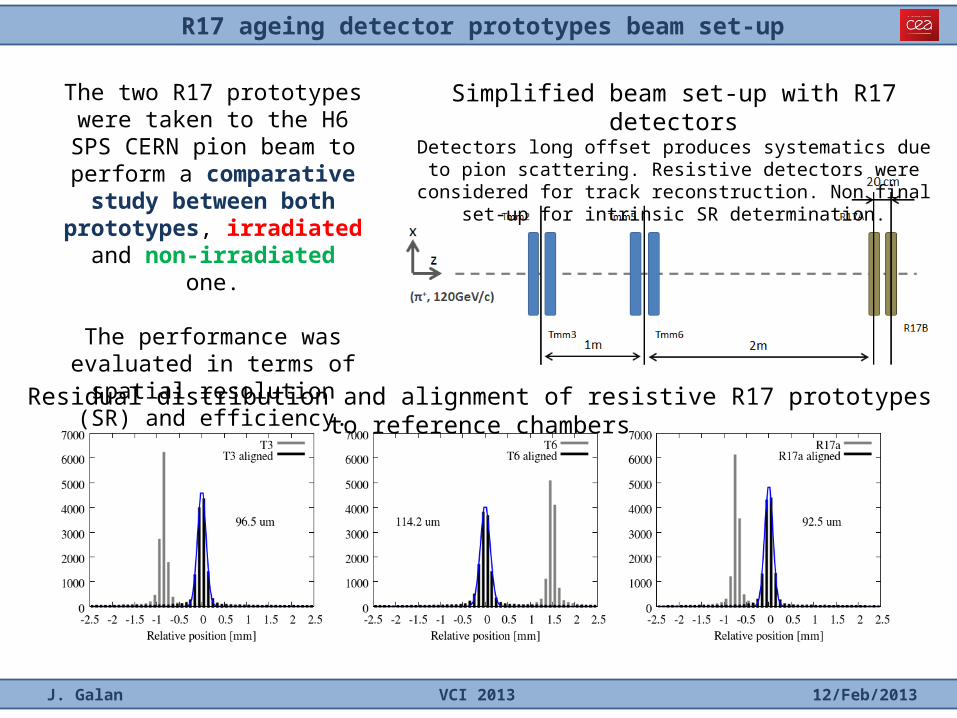
R17 ageing detector prototypes beam set-up
J. Galan VCI 2013 12/Feb/2013
Residual distribution and alignment of resistive R17 prototypes to reference chambers
Simplified beam set-up with R17 detectorsDetectors long offset produces systematics due to pion scattering.
Resistive detectors were considered for track reconstruction. Non final set-up for intrinsic SR determination.
The two R17 prototypes were taken to the H6 SPS CERN pion
beam to perform a comparative study between both prototypes,
irradiated and non-irradiated one.
The performance was evaluated in terms of spatial resolution
(SR) and efficiency.
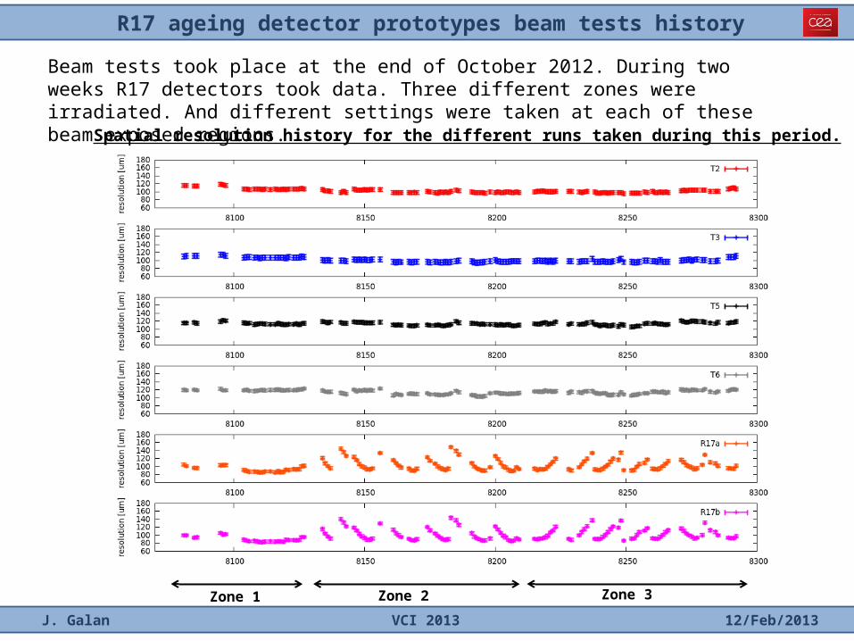
R17 ageing detector prototypes beam tests history
J. Galan VCI 2013 12/Feb/2013
Beam tests took place at the end of October 2012. During two weeks R17 detectors took data. Three different zones were irradiated. And different settings were taken at each of these beam exposed regions.
Zone 1 Zone 2 Zone 3
Spatial resolution history for the different runs taken during this period.
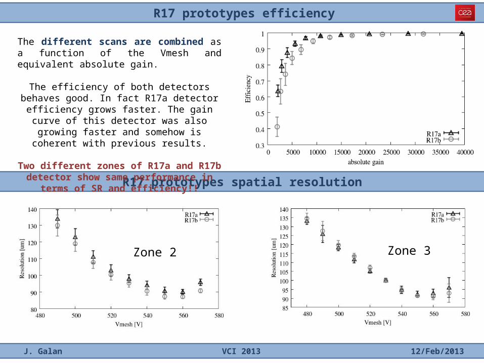
R17 prototypes efficiency
J. Galan VCI 2013 12/Feb/2013
R17 prototypes spatial resolution
Zone 2 Zone 3
The different scans are combined as a function of the Vmesh and equivalent absolute gain.
The efficiency of both detectors behaves good. In fact R17a detector efficiency grows faster. The gain curve
of this detector was also growing faster and somehow is coherent with previous results.
Two different zones of R17a and R17b detector show same performance in terms of SR and
efficiency!!
Summary and conclusions
J. Galan VCI 2013 12/Feb/2013
Mechanical design concept is ready and PCB strips within required precision.
Resistive technology shows robustness and it is a mature technology now.
Different nature irradiation processes (X-ray, neutron, gamma and alpha) took place in one of these resistive prototypes.
During the different ageing periods the irradiated detector response does not show performance decrease and its performance is comparable to that performance achieved with a similar non-irradiated detector.
Several additional tests have proven the capability of Micromegas chambers to reconstruct the track and determine the spatial resolution of this track within the required precision.
Backup. Spatial resolution for different angle tracks
J. Galan VCI 2013 12/Feb/2013
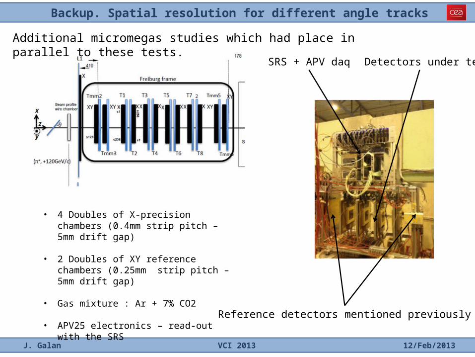
• 4 Doubles of X-precision chambers (0.4mm strip pitch – 5mm drift gap)
• 2 Doubles of XY reference chambers (0.25mm strip pitch – 5mm drift gap)
• Gas mixture : Ar + 7% CO2
• APV25 electronics – read-out with the SRS
Additional micromegas studies which had place in parallel to these tests.
Reference detectors mentioned previously
SRS + APV daq Detectors under test
Backup. Spatial resolution
J. Galan VCI 2013 12/Feb/2013
t2t1
t4t3
t5
t0
X (mm)x (mm)
y (m
m)
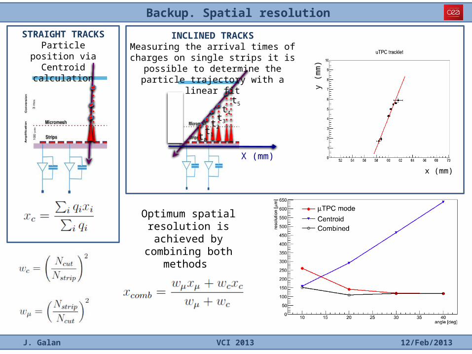
STRAIGHT TRACKSParticle position via Centroid calculation
INCLINED TRACKSMeasuring the arrival times of charges on single strips it is possible to determine the
particle trajectory with a linear fit
Optimum spatial resolution is achieved by combining both
methods
Backup. Micromegas detectors pattern precision
J. Galan VCI 2013 12/Feb/2013
Backup. Micromegas detectors assembly. Non-bulked Micromegas.
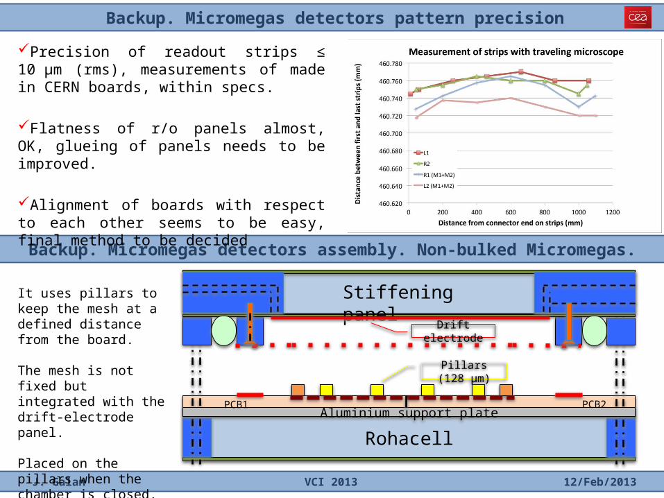
RohacellAluminium support plate
Stiffening panel
Drift electrode
Pillars (128 µm)
PCB1 PCB2
It uses pillars to keep the mesh at a defined distance from the board.
The mesh is not fixed but integrated with the drift-electrode panel.
Placed on the pillars when the chamber is closed.
Precision of readout strips ≤ 10 µm (rms), measurements of made in CERN boards, within specs.
Flatness of r/o panels almost, OK, glueing of panels needs to be improved.
Alignment of boards with respect to each other seems to be easy, final method to be decided