Embed Size (px)
Citation preview
Installation Note
Part Number E4440-90255Printed in USA August 2004
Agilent PSA Series Spectrum AnalyzersOption 124 Y-Axis Video Output Retrofit Kit
Notice.
The information contained in this document is subject to change without notice.
Agilent Technologies makes no warranty of any kind with regard to this material, including but not limited to, the implied warranties of merchantability and fitness for a particular purpose. Agilent Technologies shall not be liable for errors contained herein or for incidental or consequential damages in connection with the furnishing, performance, or use of this material.
© Copyright 2004 Agilent Technologies, Inc.
Installation Note E4440-90255 3
Y-Axis Video Output Installation Kit
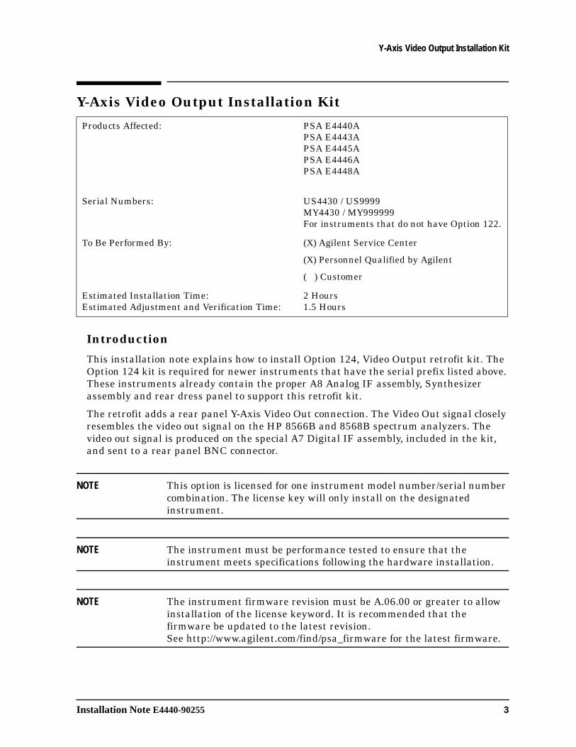
Y-Axis Video Output Installation Kit
Introduction
This installation note explains how to install Option 124, Video Output retrofit kit. The Option 124 kit is required for newer instruments that have the serial prefix listed above. These instruments already contain the proper A8 Analog IF assembly, Synthesizer assembly and rear dress panel to support this retrofit kit.
The retrofit adds a rear panel Y-Axis Video Out connection. The Video Out signal closely resembles the video out signal on the HP 8566B and 8568B spectrum analyzers. The video out signal is produced on the special A7 Digital IF assembly, included in the kit, and sent to a rear panel BNC connector.
NOTE This option is licensed for one instrument model number/serial number combination. The license key will only install on the designated instrument.
NOTE The instrument must be performance tested to ensure that the instrument meets specifications following the hardware installation.
NOTE The instrument firmware revision must be A.06.00 or greater to allow installation of the license keyword. It is recommended that the firmware be updated to the latest revision. See http://www.agilent.com/find/psa_firmware for the latest firmware.
Products Affected: PSA E4440APSA E4443APSA E4445APSA E4446APSA E4448A
Serial Numbers: US4430 / US9999MY4430 / MY999999For instruments that do not have Option 122.
To Be Performed By: (X) Agilent Service Center
(X) Personnel Qualified by Agilent
( ) Customer
Estimated Installation Time: Estimated Adjustment and Verification Time:
2 Hours1.5 Hours
4 Installation Note E4440-90255
Y-Axis Video Output Installation Kit
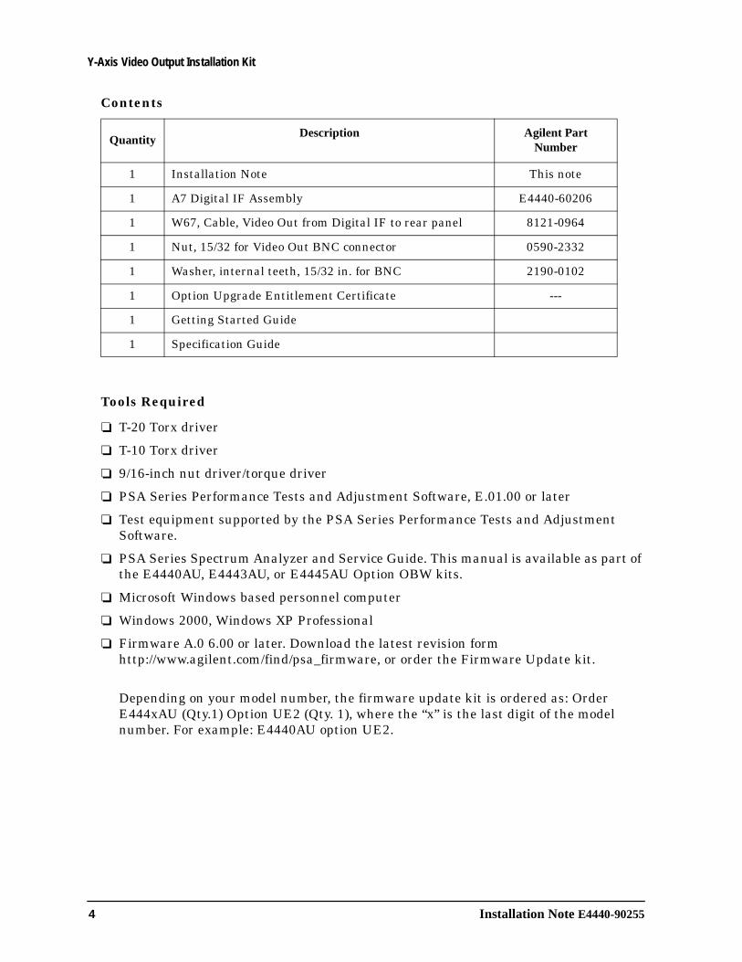
Contents
Tools Required
❏ T-20 Torx driver
❏ T-10 Torx driver
❏ 9/16-inch nut driver/torque driver
❏ PSA Series Performance Tests and Adjustment Software, E.01.00 or later
❏ Test equipment supported by the PSA Series Performance Tests and Adjustment Software.
❏ PSA Series Spectrum Analyzer and Service Guide. This manual is available as part of the E4440AU, E4443AU, or E4445AU Option OBW kits.
❏ Microsoft Windows based personnel computer
❏ Windows 2000, Windows XP Professional
❏ Firmware A.0 6.00 or later. Download the latest revision form http://www.agilent.com/find/psa_firmware, or order the Firmware Update kit.
Depending on your model number, the firmware update kit is ordered as: Order E444xAU (Qty.1) Option UE2 (Qty. 1), where the “x” is the last digit of the model number. For example: E4440AU option UE2.
QuantityDescription Agilent Part
Number
1 Installation Note This note
1 A7 Digital IF Assembly E4440-60206
1 W67, Cable, Video Out from Digital IF to rear panel 8121-0964
1 Nut, 15/32 for Video Out BNC connector 0590-2332
1 Washer, internal teeth, 15/32 in. for BNC 2190-0102
1 Option Upgrade Entitlement Certificate ---
1 Getting Started Guide
1 Specification Guide
Installation Note E4440-90255 5
Installation Procedure
Installation Procedure
Install Firmware A.06.00 or Greater if Needed
1. Press System, More, Show System. The Firmware Revision needs to be A.06.00 or later.
2. If the firmware needs to be updated, do the following: Download the PSA Update Program and the PSA Firmware Procedure from http://www.agilent.com/find/psa_firmware. Follow the directions to install the firmware.
Alternate Method: Install the Firmware Update Kit E4440AU Option UE2. Follow the directions in the kit.
Remove the Outer Case
CAUTION If the instrument is placed on its face during any of the following procedures, be sure to use a soft surface or soft cloth to avoid damage to the front panel, keys, or input connector.
1. Disconnect the instrument from ac power.
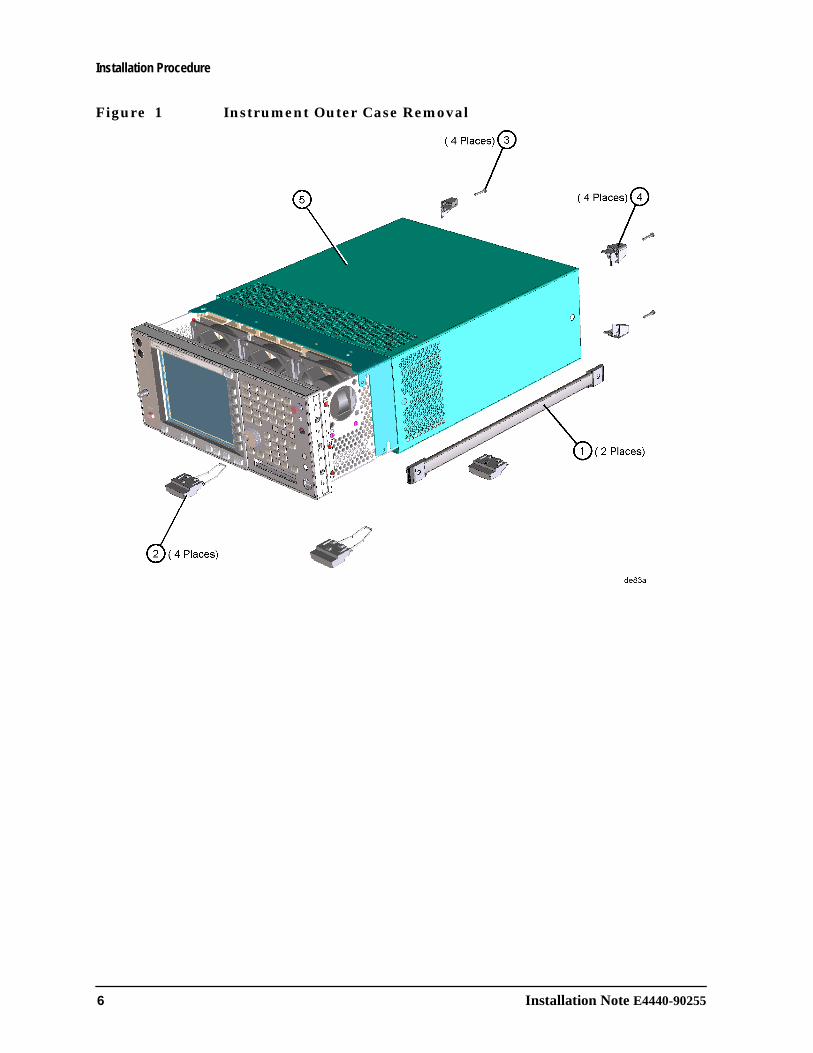
2. Refer to Figure 1. Remove the two handles on the sides of the instrument as shown. Use the T-20 driver to loosen the screws that attach each handle (1). Remove the handles.
3. Remove the four bottom feet (2). Lift up on the tabs on the feet, and slide the feet in the direction indicated by the arrows.
4. Remove the four screws (3) that hold the rear feet (4) in place.
5. Pull the instrument cover (5) off toward the rear of the instrument.
6 Installation Note E4440-90255
Installation Procedure
Figure 1 Instrument Outer Case Removal
Installation Note E4440-90255 7
Installation Procedure
Remove the Top Brace
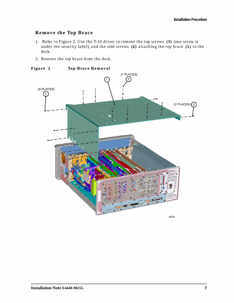
1. Refer to Figure 2. Use the T-10 driver to remove the top screws (3) (one screw is under the security label), and the side screws (2) attaching the top brace (1) to the deck.
2. Remove the top brace from the deck.
Figure 2 Top Brace Removal
8 Installation Note E4440-90255
Installation Procedure
Installing the Retrofit Kit
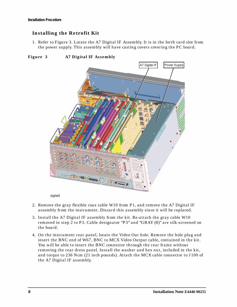
1. Refer to Figure 3. Locate the A7 Digital IF Assembly. It is in the forth card slot from the power supply. This assembly will have casting covers covering the PC board.
Figure 3 A7 Digital IF Assembly
2. Remove the gray flexible coax cable W10 from P1, and remove the A7 Digital IF assembly from the instrument. Discard this assembly since it will be replaced.
3. Install the A7 Digital IF assembly from the kit. Re-attach the gray cable W10 removed in step 2 to P3. Cable designator “P3” and “GRAY (8)” are silk-screened on the board.
4. On the instrument rear panel, locate the Video Out hole. Remove the hole plug and insert the BNC end of W67, BNC to MCX Video Output cable, contained in the kit. You will be able to insert the BNC connector through the rear frame without removing the rear dress panel. Install the washer and hex nut, included in the kit, and torque to 236 Ncm (21 inch pounds). Attach the MCX cable connector to J100 of the A7 Digital IF assembly.
Installation Note E4440-90255 9
Installation Procedure
Replace the Top Brace and Outer Case
1. Refer to Figure 2. Carefully position the top brace on the deck. The alignment pin at the center of the web/fan assembly must mate with the alignment hole on the top brace. Make sure that no coaxial cables will get pinched underneath the brace.
2. Use the T-10 driver to replace and tighten the top screws first; then replace the side screws. Torque to 101 Ncm (9 in-lb).
3. Refer to Figure 1. Slide the instrument cover back onto the deck from the rear. The seam on the cover should be on the bottom. Be sure the cover seats into the gasket groove in the front frame.
4. Replace the four rear feet onto the rear of the instrument. Torque to 236 Ncm (21 in-lb).
5. Use the T-20 driver to replace the handles. Torque to 236 Ncm (21 in-lb).
6. Replace the four bottom feet by pressing them into the holes in the case and sliding them in the opposite direction of the arrows until they click into place. Note that the feet at the front have the tilt stands.

10 Installation Note E4440-90255
Installation Procedure
Installing the Option Designator and License Keyword
NOTE The option designator 124 and the license keyword must be entered into instrument memory in addition to the correct firmware before the hardware will function.
1. Follow the directions on the Option Upgrade Entitlement Certificate included in the kit. A License Key Certificate that contains the license keyword will be e-mailed to you.
2. Plug in the instrument and power up.
3. On the instrument front panel press: System, More, until the Licensing softkey is visible. Press Licensing and Option. This will activate the alpha editor menu. Use the alpha editor and the front panel numerical keypad to enter the option designator 124. Press the Enter key. Note that 124 now appears on the Option key.
4. Press License Key. The license key number is a hexadecimal number that will require the entry of both letters and numbers. Use the alpha editor and the front panel numerical keypad to enter the license key number. Your entry will appear in the active function area of the display. If you make a typing error, use the backspace key to correct the error. Check the license key number you entered. Press Enter, Activate License.
5. Cycle instrument power and allow the instrument to perform the auto align routine. Press System, More, Show System and verify that 124 appears in the option field.
Installation Note E4440-90255 11
Installation Procedure
Verify the Option
Connect a voltmeter to the rear panel Video Out port of the PSA. Set the voltmeter to measure DC volts.
1. With the instrument is spectrum analysis mode, Preset the instrument.
2. Select the internal amplitude reference by pressing Input/Output, Input Port, and selecting the Amptd Ref.
3. Tune the analyzer to 50 MHz. Frequency, 50 MHz.
4. Set the analyzer to 5 dB/div. Amplitude, Scale/Div, 5 dB
5. Set the analyzer to zero span. Span, Zero Span.
6. Place the displayed signal at mid screen by pressing Amplitude, and adjusting the reference level until the signal is as close as possible to exactly mid screen. The voltmeter should read 0.5 volts.
7. Adjust the reference level to place the signal exactly on the top graticule line. The voltmeter should read 1 V.
NOTE The signal trace cannot be displayed above the top graticule line. However, the analyzer will measure signals above the top graticule line. Therefore the Video Output will be driven above 1 V even though it appears the on screen trace is only at the top graticule line.
8. Adjust the reference level to place the signal on the bottom graticule line. The voltmeter should read 0V.
9. Notice also that as the signal is moved up and down the screen, the voltmeter reading changes 0.1V per graticule division.
12 Installation Note E4440-90255
Installation Procedure
Performance Tests Required
The following tests are required to assure the installation was performed correctly. The instrument may not have been in spec before the retrofit was begun. Performing only these tests does not guarantee the instrument meets specifications.
There are no adjustments on the Digital IF assembly.
NOTE This procedure requires the use of the PSA Series Performance Tests and Adjustment Software.
For assistance, contact your nearest Agilent Technologies Sales and Service Office. To find your local Agilent office access the following URL or call the following telephone number:
http://www.agilent.com/find/assist
1-800-452-4844 (8am-8pm EST)
Performance Test Name
Absolute Amplitude Accuracy Test
Display Scale Fidelity Test
Resolution Bandwidth Switching Test
Power Bandwidth Accuracy Test


![Seam - ####### [###20080327] - JBoss...Table of Contents JBoss Seam## .....xi 1. Seam ## .....1](https://img.pdfslide.net/doc/110x75/60d604b5fa8e121d9f6a07dc/seam-20080327-jboss-table-of-contents-jboss-seam-xi.jpg)