Embed Size (px)
Citation preview
8/15/2019 AGMA 923-B05
http://slidepdf.com/reader/full/agma-923-b05 1/39
AGMA INFORMATION SHEET(This Information Sheet is NOT an AG MA Standard)
A G M A 9 2 3 - B 0 5
AGMA 923- B05
AMERICAN GEAR MANUFACTURERS ASSOCIATION
Metallurgical Specifications for Steel
Gearing
8/15/2019 AGMA 923-B05
http://slidepdf.com/reader/full/agma-923-b05 2/39
ii
Metallurgical Specifications for Steel Gearing AGMA 923--B05
CAUTION NOTICE: AGMA technical publications are subject to constant improvement,
revision, or withdrawal as dictated by experience. Any person who refers to any AGMA
technical publication should be sure that the publicationis the latest available from the As-
sociation on the subject matter.
[Tables or other self--supporting sections may be quoted or extracted. Citations should
read: See AGMA 923--B05, Metallurgical Specifications for Steel Gearing, published by
the American Gear Manufacturers Association, 500 Montgomery Street, Suite 350,
Alexandria, Virginia 22314, http://www.agma.org.]
Approved May 3, 2005
ABSTRACT
This document identifies metallurgical quality characteristics which are important to the performance of steel
gearing. The AGMA gear rating standards identify performance levels of gearing by heat treatmentmethodand
grade number. For each heat treatment method and AGMA grade number, acceptance criteria are given for
various metallurgical characteristics identified in this document.
Published by
American Gear Manufacturers Association500 Montgomery Street, Suite 350, Alexandria, Virginia 22314
Copyright © 2005 by American Gear Manufacturers Association
All rights reserved.
No part of this publication may be reproduced in any form, in an electronicretrieval system or otherwise, without prior written permission of the publisher.
Printed in the United States of America
ISBN: 1--55589--848--3
American Gear
Manufacturers
Association
8/15/2019 AGMA 923-B05
http://slidepdf.com/reader/full/agma-923-b05 3/39
AGMA 923--B05AMERICAN GEAR MANUFACTURERS ASSOCIATION
iii© AGMA 2005 ---- All rights reserved
Contents
Page
Foreword iv. . . . . . . . . . . . . . . . . . . . . . . . . . . . . . . . . . . . . . . . . . . . . . . . . . . . . . . . . . . . . . .
1 Scope 1. . . . . . . . . . . . . . . . . . . . . . . . . . . . . . . . . . . . . . . . . . . . . . . . . . . . . . . . . . . . .
2 Normative references 1. . . . . . . . . . . . . . . . . . . . . . . . . . . . . . . . . . . . . . . . . . . . . . .
3 Definitions 3. . . . . . . . . . . . . . . . . . . . . . . . . . . . . . . . . . . . . . . . . . . . . . . . . . . . . . . . .
4 Procedures 11. . . . . . . . . . . . . . . . . . . . . . . . . . . . . . . . . . . . . . . . . . . . . . . . . . . . . . .
5 Metallurgical requirements 14. . . . . . . . . . . . . . . . . . . . . . . . . . . . . . . . . . . . . . . . . .
Bibliography 31. . . . . . . . . . . . . . . . . . . . . . . . . . . . . . . . . . . . . . . . . . . . . . . . . . . . . . . . . . .
Tables
1 Metallurgical characteristics for through hardened gearing 15. . . . . . . . . . . . . . .
2 Metallurgical characteristics for carburize and hardened gearing 17. . . . . . . . .
3 Metallurgical characteristics for induction or flame hardened gearing 22. . . . . .
4 Metallurgical characteristics for nitrided gearing 27. . . . . . . . . . . . . . . . . . . . . . . .
Figures
1 Continuous carbide network 4. . . . . . . . . . . . . . . . . . . . . . . . . . . . . . . . . . . . . . . . . .
2 Semi--continuous carbide network 4. . . . . . . . . . . . . . . . . . . . . . . . . . . . . . . . . . . . .3 Discontinuous carbides 4. . . . . . . . . . . . . . . . . . . . . . . . . . . . . . . . . . . . . . . . . . . . . .
4 Dispersed carbides 4. . . . . . . . . . . . . . . . . . . . . . . . . . . . . . . . . . . . . . . . . . . . . . . . .
5 Solid on shaft pinion blank 5. . . . . . . . . . . . . . . . . . . . . . . . . . . . . . . . . . . . . . . . . . .
6 Bore style gearing blank 5. . . . . . . . . . . . . . . . . . . . . . . . . . . . . . . . . . . . . . . . . . . . .
7 Disc style gearing blank 5. . . . . . . . . . . . . . . . . . . . . . . . . . . . . . . . . . . . . . . . . . . . .
8 Web style gear blank 6. . . . . . . . . . . . . . . . . . . . . . . . . . . . . . . . . . . . . . . . . . . . . . . .
9 Intergranular oxidation in carburized gearing 7. . . . . . . . . . . . . . . . . . . . . . . . . . . .
10 Non--martensitic transformation products in carburized gearing 8. . . . . . . . . . .
11 Tempered martensite and 5% retained austenite in carburized gearing 10. . . .
12 Tempered martensite and 20% retained austenite in carburized gearing 10. . .
13 Tempered martensite and 30% retained austenite in carburized gearing 10. . .
14 Variations in hardening pattern obtainable on gear teeth with flame orinduction hardening 26. . . . . . . . . . . . . . . . . . . . . . . . . . . . . . . . . . . . . . . . . . . . . . . .
8/15/2019 AGMA 923-B05
http://slidepdf.com/reader/full/agma-923-b05 4/39
AGMA 923--B05 AMERICAN GEAR MANUFACTURERS ASSOCIATION
iv © AGMA 2005 ---- All rights reserved
Foreword
[The foreword, footnotes and annexes, if any, in this document are provided for
informational purposes only and are not to be construed as a part of AGMA Information
Sheet 923--B05, Metallurgical Specifications for Steel Gearing.]
In November, 1984, an ad hoc Metallurgy and Gear Rating Committee met to define the
factors required to qualifythe variousmetallurgical quality grades that were to be introduced
into thegear rating standard that eventuallybecame ANSI/AGMA 2001-- B88, Fundamental Rating Factors and Calculation Methods for Involute Spur and Helical Gear Teeth.
In May, 1988, ANSI/AGMA 6033--A88, Standard for Marine Propulsion Gear Units -- Part 1,
Materials, was published using a short list of metallurgical factors in table form.
In September, 1988, ANSI/AGMA 2001--B88 was published using metallurgical factors in
table form.
Starting in July, 1992, AGMA representatives participated in writing ISO 6336--5,
Calculation of Load Capacity of Spur and Helical Gears -- Part 5: Strength and Quality of
Materials , which was a modification of the tables in ANSI/AGMA and DIN Standards.
In February, 1993,AGMA 6002--B93, Design Guide for Vehicle Spur andHelicalGears ,was
published using a modified version of the tables used in ANSI/AGMA 2001--B88.
In September, 1993, the AGMA Metallurgy and Materials Committee accepted the task ofconsolidating the various tables to avoid redundancies and conflicting requirements, and
started work on AGMA 923--A00, Metallurgical Specifications for Steel Gearing.
In January, 1995, a revised ANSI/AGMA 2001--C95 was published using a version of the
ANSI/AGMA 2001--B88 tables as revised by the AGMA Helical Gear Rating Committee.
In November, 1997, a revised ANSI/AGMA 2003--B97, Rating the Pitting Resistance and
Bending Strength of Generated Straight Bevel, Zerol Bevel and Spiral Bevel Gear Teeth ,
was published using a version of theANSI/AGMA2001--B88 tablesas revised by theAGMA
Bevel Gearing Committee.
The committee reviewed all metallurgical tables of the gear rating standards ANSI/AGMA
2001--B88, ANSI/AGMA 2003--A86, and ISO 6336--5:1996 and their proposed revisions to
develop consolidated tables describing the metallurgical characteristics associated witheach specific type of heat treatment and metallurgical quality grade. Effort was made to
reference ISO specifications where possible. The consolidated tables were submitted to
the gear rating committees for their agreement and are published here for reference by
other standards.
AGMA’s goal is to develop a consistent metallurgical specification which reflects the quality
requirementsfor steel gearing. AGMA 923--A00 wassuch a document,and wasintended to
be consistent with the applicable portions of ISO 6336--5:1996, to the extent possible while
the two standards were in parallel development. The AGMA Technical Division Executive
Committee approved the publication of AGMA 923--A00 in August, 2000.
This edition of the information sheet, AGMA 923--B05, incorporates changes to item 8,
microstructure, of table 1, Metallurgical characteristics for through hardened gearing. The
balance of the document remains unchanged. The AGMA Technical Division Executive
Committee approved the publication of AGMA 923--B05 in May, 2005.
Suggestions for improvement of this information sheet will be welcome. They should be
sent to the American Gear Manufacturers Association, 500 Montgomery Street, Suite 350,
Alexandria, Virginia 22314.
8/15/2019 AGMA 923-B05
http://slidepdf.com/reader/full/agma-923-b05 5/39
AGMA 923--B05AMERICAN GEAR MANUFACTURERS ASSOCIATION
v© AGMA 2005 ---- All rights reserved
PERSONNEL of the AGMA Metallurgy and Materials Committee
Chairman: Phil Terry Lufkin Industries, Inc.. . . . . . . . . . . . . . . . . . . . . . . . . . . . . . . .
Vice Chairman: Dale J. Weires Boeing Defense & Space Group. . . . . . . . . . . . . . . . . . . . . . .
ACTIVE MEMBERS
C. Berndt Caterpillar, Inc.. . . . . . . . . . . . . . . . . . . . . . . . . .I. Botto FFE Minerals. . . . . . . . . . . . . . . . . . . . . . . . . . . .
D. Breuer Metal Improvement Company. . . . . . . . . . . . . . . . . . . . . . . . .R.J. Cunningham Consultant. . . . . . . . . . . . . . . . . . .G. Diehl Philadelphia Gear Corporation. . . . . . . . . . . . . . . . . . . . . . . . . . .D. Herring The Herring Group, Inc.. . . . . . . . . . . . . . . . . . . . . . . . .D.R. McVittie Gear Engineers, Inc.. . . . . . . . . . . . . . . . . . . . . .J. Mertz Falk Corporation. . . . . . . . . . . . . . . . . . . . . . . . . . .R.L. Schwettman Xtek, Inc.. . . . . . . . . . . . . . . . . . .M. Stein Applied Process Southridge, Inc.. . . . . . . . . . . . . . . . . . . . . . . . . . .J.B. Walenta Caterpillar, Inc.. . . . . . . . . . . . . . . . . . . . . . .L.L. Witte General Motors Corporation/Allison Transmission Division. . . . . . . . . . . . . . . . . . . . . . . . . .

8/15/2019 AGMA 923-B05
http://slidepdf.com/reader/full/agma-923-b05 6/39
AGMA 923--B05 AMERICAN GEAR MANUFACTURERS ASSOCIATION
vi © AGMA 2005 ---- All rights reserved
(This page is intentionally blank)
8/15/2019 AGMA 923-B05
http://slidepdf.com/reader/full/agma-923-b05 7/39
1
© AGMA 2005 ---- All rights reserved
AGMA 923--B05AMERICAN GEAR MANUFACTURERS ASSOCIATION
American Gear ManufacturersAssociation --
MetallurgicalSpecifications for Steel
Gearing
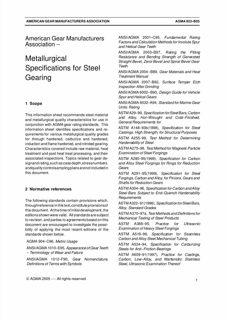
1 Scope
This information sheet recommends steel material
and metallurgical quality characteristics for use in
conjunction with AGMA gear rating standards. This
information sheet identifies specifications and re-
quirements for various metallurgical quality grades
for through hardened, carburize and hardened,
induction and flame hardened, and nitrided gearing.
Characteristics covered include raw material, heat
treatment and post heat treat processing, and their
associated inspections. Topics related to gear de-
signand rating,such as case depth,stressnumbers,
andquality controlsampling plans arenot included inthis document.
2 Normative references
The following standards contain provisions which,
throughreference in this text,constitute provisionsof
this document. At the time of initial development, the
editions shown were valid. All standards are subject
to revision, and parties to agreements based on this
document are encouraged to investigate the possi-bility of applying the most recent editions of the
standards shown below.
AGMA 904--C96, Metric Usage
ANSI/AGMA 1010--E95, Appearance of Gear Teeth
-- Terminology of Wear and Failure
ANSI/AGMA 1012--F90, Gear Nomenclature,
Definitions of Terms with Symbols
ANSI/AGMA 2001--C95, Fundamental Rating
Factors and Calculation Methods for Involute Spur
and Helical Gear Teeth
ANSI/AGMA 2003--B97, Rating the Pitting
Resistance and Bending Strength of Generated Straight Bevel, Zerol Bevel and Spiral Bevel Gear
Teeth
ANSI/AGMA 2004--B89, Gear Materials and Heat
Treatment Manual
ANSI/AGMA 2007--B92, Surface Temper Etch
Inspection After Grinding
ANSI/AGMA 6002--B93, Design Guide for Vehicle
Spur and Helical Gears
ANSI/AGMA 6032--A94, Standard for Marine Gear
Units: Rating
ASTM A29--99, Specification forSteel Bars, Carbon and Alloy, Hot--Wrought and Cold--Finished,
General Requirements for
ASTM A148--93b(1998), Specification for Steel
Castings, High Strength, for Structural Purposes
ASTM A255--99, Test Method for Determining
Hardenability of Steel
ASTM A275--98, Test Method for Magnetic Particle
Examination of Steel Forgings
ASTM A290--95(1999), Specification for Carbon
and Alloy Steel Forgings for Rings for Reduction
Gears ASTM A291--95(1999), Specification for Steel
Forgings, Carbon and Alloy, for Pinions, Gears and
Shafts for Reduction Gears
ASTM A304--96, Specification for Carbon and Alloy
Steel Bars Subject to End--Quench Hardenability
Requirements
ASTM A322--91(1996), Specification for Steel Bars,
Alloy, Standard Grades
ASTM A370--97a, Test Methods and Definitions for
Mechanical Testing of Steel Products
ASTM A388--95, Practice for Ultrasonic Examination of Heavy Steel Forgings
ASTM A519--96, Specification for Seamless
Carbon and Alloy Steel Mechanical Tubing
ASTM A534--94, Specification for Carburizing
Steels for Anti--Friction Bearings
ASTM A609--91(1997), Practice for Castings,
Carbon, Low--Alloy, and Martensitic Stainless
Steel, Ultrasonic Examination Thereof
8/15/2019 AGMA 923-B05
http://slidepdf.com/reader/full/agma-923-b05 8/39
AGMA 923--B05 AMERICAN GEAR MANUFACTURERS ASSOCIATION
2 © AGMA 2005 ---- All rights reserved
ASTM A751--96, Test Methods, Practices, and
Terminology for Chemical Analysis of Steel
Products
ASTM A837--91(1996)1, Specification for Steel
Forgings, Alloy, for Carburizing Applications
ASTM A866--94, Specification for Medium Carbon
Anti--Friction Bearing Steel
ASTM A919--84 (1993)1, Terminology Relating to Heat Treatment of Metals
ASTM A941--99a, Terminology Relating to Steel,
Stainless Steel, Related Alloys, and Ferroalloys
ASTM A956--97, Test Method for Equotip Hardness
Testing of Steel Products
ASTM E3--95, Practice for Preparation of
Metallographic Specimens
ASTM E8--99, Test Methods for Tension Testing of
Metallic Materials
ASTM E10--98, Test Method for Brinell Hardness of Metallic Materials
ASTM E18--98, Test Methods for Rockwell
Hardness and Rockwell Superficial Hardness of
Metallic Materials
ASTM E23--98, Test Methods for Notched Bar
Impact Testing of Metallic Materials
ASTM E45--972, Test Methods for Determining the
Inclusion Content of Steel
ASTM E92--82(1997)2, Test Method for Vickers
Hardness of Metallic Materials ASTM E110--82(1997)2, Test Method for
Indentation Hardness of Metallic Materials by
Portable Hardness Testers
ASTM E112--96, Test Methods for Determining
Average Grain Size
ASTM E125--63(1997), Reference Photographs for
Magnetic Particle Indications on Ferrous Castings
ASTM E140--971, HardnessConversion Tables for
Metals (Relationship Among Brinell Hardness,
Vickers Hardness, Rockwell Hardness, Rockwell
Superficial Hardness, Knoop Hardness, and
Scleroscope Hardness)
ASTM E350--95(1997)1, Test Methods for
Chemical Analysis of Carbon Steel, Low--Alloy
Steel, Silicon Electrical Steel, Ingot Iron, and
Wrought Iron
ASTM E384--89(1997)2, Test Method for
Microhardness of Materials
ASTM E407--99, Practice for Microetching Metals
and Alloys
ASTM E415--99, Test Method for Optical Emission
Vacuum Spectrometric Analysis of Carbon and
Low--Alloy Steel
ASTM E428--92, Practice for Fabrication and
Control of Steel Reference Blocks Used in
Ultrasonic Inspection ASTM E709--95, Guide for Magnetic Particle
Examination
ASTM E1077--91, Test Methods for Estimating the
Depth of Decarburization of Steel Specimens
ASTM E1444--94a, Practice for Magnetic Particle
Examination
ISO 642:1979, Steel -- Hardenability test by end
quenching (Jominy test)
ISO 643:1983, Steels -- Micrographic determination
of the ferritic or austenitic grain size ISO 683--1:1987, Heat--treatablesteels, alloy steels
and free--cutting steels -- Part 1: Direct --hardening
unalloyed and low--alloyed wrought steel in form of
different black products
ISO 683--11:1987, Heat--treatable steels, alloy
steels and free--cutting steels -- Part 11: Wrought
case--hardening steels
ISO 4967:1979, Steel -- Determination of content of
non--metallic inclusions -- micrographic method
using standard diagrams
ISO 6336--5:1996, Calculation of load capacity of
spurand helical gears -- Part5: Strengthand quality
of materials
ISO 14104:1995, Surface temper etch inspection
after grinding
SAE/AMS 2300G, Premium Aircraft--Quality Steel
Cleanliness, Magnetic Particle Inspection
Procedure
SAE/AMS 2301H, Cleanliness, Aircraft Quality
Steel Magnetic Particle Inspection Procedure
SAE/AMS 2304, Special Aircraft--Quality Steel Cleanliness, Magnetic Particle Inspection
Procedure
SAE/AMS--S--13165, Shot Peening of Metal Parts
SAE J419 Dec 83, Methods of Measuring
Decarburization
SAE J422 Dec 83, Microscopic Determination of
Inclusions in Steels
8/15/2019 AGMA 923-B05
http://slidepdf.com/reader/full/agma-923-b05 9/39
AGMA 923--B05AMERICAN GEAR MANUFACTURERS ASSOCIATION
3
© AGMA 2005 ---- All rights reserved
SAE J423 Dec 83, Methods of Measuring Case
Depth
SAE J864 May 93, Surface Hardness Testing with
Files
3 Definitions
The terms used in this document, wherever applica-
ble, conform to AGMA 904--B89, ANSI/AGMA
1012--F90, and ASTM A919, but they have been
modified to cover only those concepts applicable to
this document. For definitions of technical terms not
included in this clause, see ANSI/AGMA 1012--F90,
ANSI/AGMA 2004--B89, ASTM A919, and ASTM
A941. Key terms used in this document are defined
as follows:
NOTE: These definitions may differ from those in other
AGMA publications. The user should not assume thatfamiliar terms can be used without a careful study of
their definitions.
alloy steel: A steel containingspecified quantities of
alloying elements (other than carbon and the
commonly accepted amounts of manganese, cop-
per, silicon, sulfur, and phosphorus) added to
increase hardenability and to affect changes in
mechanical properties.
annealing: The heating to and holding at a suitable
temperature above the upper transformation tem-
perature and then cooling, typically in the furnace ata suitable rate, for reducing hardness, improving
machinability, producing a desired microstructure,or
obtaining desired mechanical properties.
austenite: A solid solution of one or more elements
in face--centered cubic iron. In carbon and low alloy
steels this phase is stable only at elevated
temperatures and is non--magnetic.
austenitizing: The forming of austenite by heating
a ferrous material into the transformation range
(partial austenitizing) or above the transformation
range (complete austenitizing).
bainite: An aggregate of ferrite and cementite
resulting from the transformation of austenite at
temperatures below the pearlite range but above the
martensite start temperature. Its appearance is
feathery if formed in the upper part of the bainite
transformation range and acicular, resembling
tempered martensite, if formed in the lower part.
banding: A segregated structure consisting of
alternating, nearly parallel bands of different chemi-
cal composition, typically aligned in the direction of
primary hot working. Segregation is frequently
expressed as a departure from the average
chemical composition. Elements which tend to
segregate are sulfur, phosphorus, carbon, silicon,
and manganese.
base hardness: The surface hardness in the tooth
area that was developed by through hardening and
not changed by subsequent heat treatments. If the
material selected has adequate hardenability for the
required hardness and section size combination,
this surface hardness represents the expected
hardness at the intersection of the root circleand the
centerline of the tooth at mid--face width. Base
hardness is applicable to through hardened, induc-
tion hardened, flame hardened, and nitrided
gearing, but not to carburize and hardened gearing.
bending strength: The bending strength of gear
teeth related to their resistance to gear tooth bending
failure. Bending failure is a fatigue phenomenon
usually resulting in cracking at the tooth root fillet.
Typical cracks and fractures are illustrated in ANSI/
AGMA 1010--E95. See standards such as ANSI/
AGMA 2001--C95, ANSI/AGMA 2003--B97,
ANSI/AGMA 6002--B93, or ANSI/AGMA 6032--A94.
capable of: The producer documents that the
material was produced with the processing steps
and controls that the producer has established to
assure compliance with the specification, but the
testing to confirm compliance is not required.
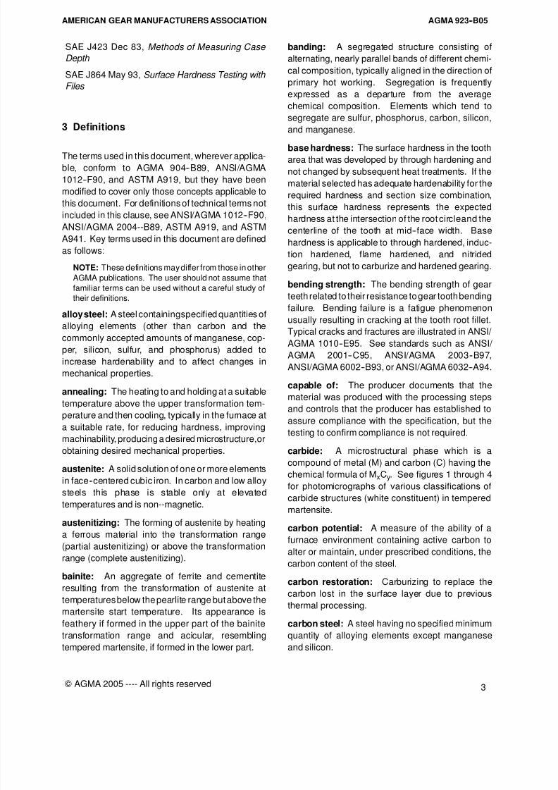
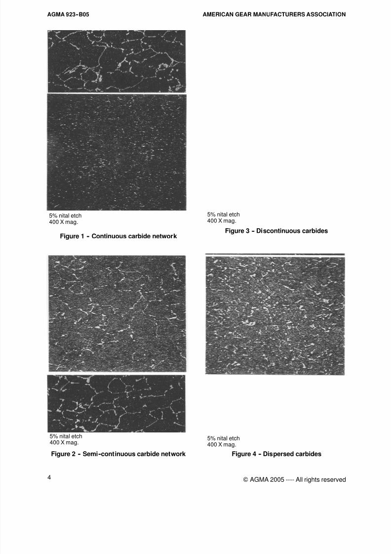
carbide: A microstructural phase which is a
compound of metal (M) and carbon (C) having the
chemical formula of MxCy. See figures 1 through 4
for photomicrographs of various classifications of
carbide structures (white constituent) in tempered
martensite.
carbon potential: A measure of the ability of a
furnace environment containing active carbon to
alter or maintain, under prescribed conditions, thecarbon content of the steel.
carbon restoration: Carburizing to replace the
carbon lost in the surface layer due to previous
thermal processing.
carbon steel: A steel having no specified minimum
quantity of alloying elements except manganese
and silicon.
8/15/2019 AGMA 923-B05
http://slidepdf.com/reader/full/agma-923-b05 10/39
AGMA 923--B05 AMERICAN GEAR MANUFACTURERS ASSOCIATION
4 © AGMA 2005 ---- All rights reserved
5% nital etch400 X mag.
Figure 1 -- Continuous carbide network
5% nital etch400 X mag.
Figure 2 -- Semi--continuous carbide network
5% nital etch400 X mag.
Figure 3 -- Discontinuous carbides
5% nital etch400 X mag.
Figure 4 -- Dispersed carbides
8/15/2019 AGMA 923-B05
http://slidepdf.com/reader/full/agma-923-b05 11/39
AGMA 923--B05AMERICAN GEAR MANUFACTURERS ASSOCIATION
5
© AGMA 2005 ---- All rights reserved
carburizing: A heat treatment process in which an
austenitized steel is brought into contact with a
carbonaceous atmosphere of sufficient carbon po-
tential to cause adsorption of carbon at the surface
and by diffusion to create a concentration gradient.
Carburizing is generally followed by quenching and
reheating (tempering) of an item to produce a
hardened and tempered case.
case: The outer portion that has been made harder
than the inner portion (see core hardness) as a result
of altered composition, microstructure, or both, by
treatments such as carburize and hardening,
induction hardening, flame hardening, and nitriding.
case depth: See the specific type of case depth
such as effective or total case depth.
case hardening: The generic terminology covering
carburize and nitride hardening applicable to steel
that change the chemical composition and micro-structure of the surface layer by adsorption of
carbon, nitrogen, or a mixture of the two and by
diffusion, create a chemical composition gradient.
Adsorption of carbon processes involve a subse-
quent quenching to harden, while adsorption of
nitrogen does not require quenching to harden.
case hardness: For carburize and hardened
gearingand induction or flame hardened gearing the
hardness is measured at 0.002--0.004 inches (0.05 --
0.10 mm) below the surface using a microhardnesstest technique.
For nitriding specifications surface hardness is
typically used rather than case hardness.
Case hardness is not to be confused with surface
hardness which is taken directly on thesurface using
a conventional or portable hardness tester.
cementite: A hard compound of iron and carbon,
known chemically as iron carbide, having the
chemical formula Fe3C.
cold treatment: The preferred terminology for
cooling carburize and hardened parts to tempera-
tures typically below minus 80°F (minus 60°C) to
reduce retained austenite. Cold treatment is also
known as sub--zero treatment or deep freezing. If
cooled to below minus 300°F (minus 185°C), the
correct terminology is deep cryogenic treatment.
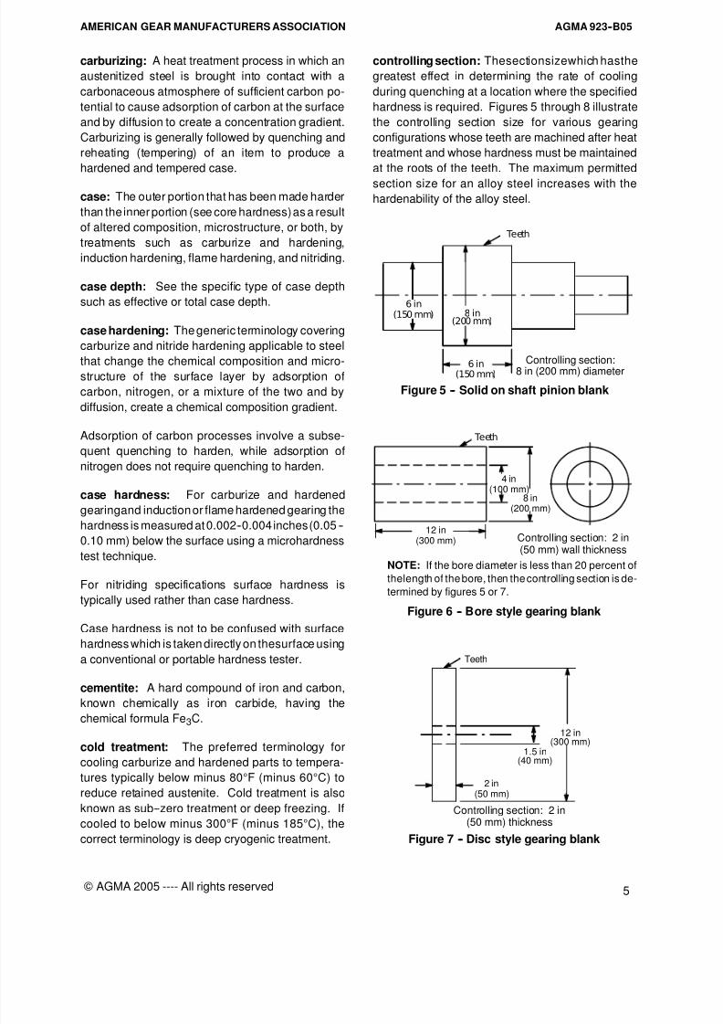
controlling section: Thesectionsizewhich hasthe
greatest effect in determining the rate of cooling
during quenching at a location where the specified
hardness is required. Figures 5 through 8 illustrate
the controlling section size for various gearing
configurations whose teeth are machined after heat
treatment and whose hardness must be maintained
at the roots of the teeth. The maximum permitted
section size for an alloy steel increases with the
hardenability of the alloy steel.
Teeth
8 in(200mm)
(150mm)6 in Controlling section:
8 in (200 mm) diameter
6 in(150mm)
Figure 5 -- Solid on shaft pinion blank
8 in(200 mm)
Teeth
Controlling section: 2 in(50 mm) wall thickness
4 in(100 mm)
12 in
(300 mm)
NOTE: If the bore diameter is less than 20 percent of
thelength of the bore, then the controlling section is de-
termined by figures 5 or 7.
Figure 6 -- Bore style gearing blank
Teeth
12 in
1.5 in(300 mm)
(40 mm)
Controlling section: 2 in(50 mm) thickness
2 in(50 mm)
Figure 7 -- Disc style gearing blank

8/15/2019 AGMA 923-B05
http://slidepdf.com/reader/full/agma-923-b05 12/39
AGMA 923--B05 AMERICAN GEAR MANUFACTURERS ASSOCIATION
6 © AGMA 2005 ---- All rights reserved
Controlling section: 2 in(50 mm) rim thickness
8”(200 mm)
32 in(800 mm)
36 in(900 mm)
Teeth
Figure 8 -- Web style gear blank
Note that a flat plate with thickness equal to the
diameter of a round bar will cool slower than the bar.
The thickness of a plate equivalent in cooling rate to
that of a round bar (equivalent controlling section
size) is 0.7 times the bar diameter.
The controlling section size for the selection of an
appropriate type of steel and specified hardness
combination must consider part configuration at the
time of heat treatment. Special stock additional
allowances, such as those used to minimize distor-
tion during heat treatment, must be considered.
converted hardness: The hardness number re-
ported on a scale different from the scale used for
hardness testing. For example an actual microhard-
ness test reading of 542 HK500 has a converted
hardnessof 50 HRC and would be properly reported
as 50 HRC (542 HK500) with the hardness numberand scale in parentheses representing the actual
testing result and method.
core hardness: The hardness at the intersection of
the root circle and the centerline of the tooth at
mid--face width that was developed during the
hardening of carburized gearing. An alternative
location is given by ISO 6336--5, table 4, item 8.
The material must have adequate hardenability for
the required hardness and section size combination
for the required core hardness to be achieved. Thequench severity must also be adequate in order to
achieve the required core hardness.
The term core hardness is applicable to carburize
and hardened gearing. Induction, flame, and nitride
hardened gearing may use the term base hardness.
The core hardness of non--tooth portions (such as
journal areas of carburize and hardened gearing), is
the hardness at a specified location such as surface,
quarter radius, mid--radius, or centerline.
decarburization: The loss of carbon from the
near--surface of a ferrous material.
deoxidizing: The removal of oxygen from molten
steel by addition of suitable elements, such as silicon
and aluminum which react with oxygen, primarily
forming discard slag.
direct quenching: The quenching of carburized
gearing directly after the carburizing operation,
generally from a reduced temperature within the
austenitic range.
effective case depth: The distance from the
finished tooth surface to a specific sub--surface
hardness value. Stock removal done after heat
treating will reduce the as heattreated effective case
depth and potentially the surface hardness.
Carburize and hardened The effective case depth is measured normal to the
finished gear surface to a location where the
hardness number is 50 HRC (542 HK500 or 515
HV500 min) by conversion from a microhardness test
result. Note that ISO 6336--5 uses 550 HV500 min,
which converts to 52.4 HRC or 583 HK500, as its
criterion for determining the effective case depth. It
is recognized that the effective case depth of
carburize and hardened gear teeth varies with
location on the gear tooth.
Induction and flame hardened For Grades 1 and 2 gearing, the effective case depth
is measured from the finished surface to a location
where the hardness number is equivalentto 10 HRC
numbers below the specified minimum surface
hardness. Grade 3 induction hardened gearing uses
the carburize and hardened definition for its effective
case depth definition. Note that ISO 6336--5 uses
the distance from the surface to the location where
the hardness is equal to 80% of the specified
minimum surface hardness as its criterion for
determining the effective case depth.
Nitrided
The effective case depth is measured from the
finished surface to a location where the hardness
number is equivalent to 40.8 HRC(421 HK500 or 400
HV500 min) by conversion from a microhardness test
result. If the core hardness is more than 38.9 HRC
(391 HK500 or380 HV500min), core hardness plus 54
HK500 or50HV500min (4.6HRC) may beused asthe
8/15/2019 AGMA 923-B05
http://slidepdf.com/reader/full/agma-923-b05 13/39
AGMA 923--B05AMERICAN GEAR MANUFACTURERS ASSOCIATION
7
© AGMA 2005 ---- All rights reserved
definition of nitrided effective case depth. Note that
this is the same definition used in ISO 6336--5.
ferrite: A solid solution of one or more elements in
body--centered cubic iron. In carbon and alloy steels
this phase is stable at room temperature.
flame hardening: A case hardening process in
which only the surface layer of the work piece is
heated by a flame to above the upper transformation
temperature and immediately quenched.
free ferrite: The ferrite that is formed directly during
cooling without simultaneous formation of carbide.
grain size: The dimensions of the grains, or
crystals, in a polycrystalline metal exclusive of
twinned regions and sub--grains when present. The
ASTM grain size is a designation bearing a relation-
ship to average intercept distance at 100 diameters
magnification. Commercial grain size is categorized
as either coarse (grain size 1--4) or fine (grain size 5or finer).
hardenability: The property of a ferrous alloy that
determines the depth and distribution of hardness
induced by quenching.
hardened depth: For induction or flame hardened
gearing, alternative terminology for effective case
depth.
hardness: See specific kind of hardness such as
base, case, core or surface.
hardness conversion chart: A published docu-
ment for use in converting from one hardness testing
scale to another.
Hardness conversion charts should be used with
great caution since discrepancies of 0.3 HRC
numbers at30 HRC to3.9 HRC numbers at60 HRC,havebeen noted between various published conver-
sion charts. Therefore, it is suggested that the
conversion chart used for testing and reporting be
specified. Some of the more popular hardness
conversion charts are found in ASTM A370, ASTM
E140, ISO 6336--5, and certain individual corporate
documents and standards. For this document,
ASTM A370 is used and should be used whenever
no other document is specified.
induction hardening: A surface hardening process
in which only the surface layer of the work piece isheated by electrically induced currents to above the
upper transformation temperature and immediately
quenched.
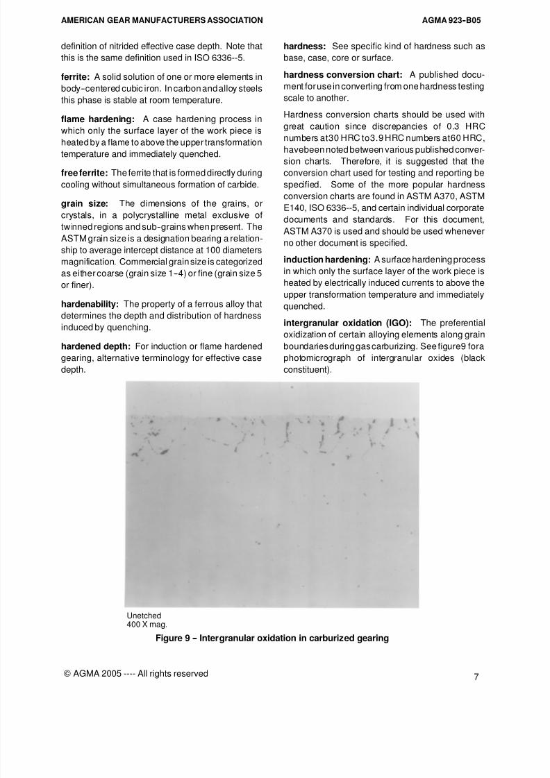
intergranular oxidation (IGO): The preferential
oxidization of certain alloying elements along grain
boundaries during gas carburizing. See figure9 fora
photomicrograph of intergranular oxides (black
constituent).
Unetched400 X mag.
Figure 9 -- Intergranular oxidation in carburized gearing
8/15/2019 AGMA 923-B05
http://slidepdf.com/reader/full/agma-923-b05 14/39
AGMA 923--B05 AMERICAN GEAR MANUFACTURERS ASSOCIATION
8 © AGMA 2005 ---- All rights reserved
linear indication: An indication with length at least
three times its width.
marquench: Quenching into a liquid media whose
temperature is above the martensite start trans-
formation temperature, typically 300 -- 500°F (150 --
260°C), held at this temperature until temperature is
uniform throughout, and then cooled to form
martensite. Marquenching is used to achievereduced distortion when compared to conventional
quenching.
martensite: A generic term for microstructures
formed by the diffusionless phase transformation of
austenite. Martensite is characterized by an acicular
or needle--like pattern in the microstructure and is
the hardest of the austenitic transformation products
in steel.
microsegregation: The non--uniformdistribution of
alloying elements, impurities, or phases observed
primarily in the microstructure of the material.
nitriding: The introduction of nascent nitrogen into
a suitable solid ferrous alloy by holding at a suitable
temperature in contact with a nitrogenous material.
Adsorption of nascent nitrogen produces case
hardening without quenching.
non--martensitic structures: Inclusive terminolo-
gy for ferrite, carbide, retained austenite, pearlite,
and bainite due to incomplete transformation to
martensite or incomplete austenization. Retained
austenite is not included in the quantitative
metallographic measurement of non--martensitic
structures.
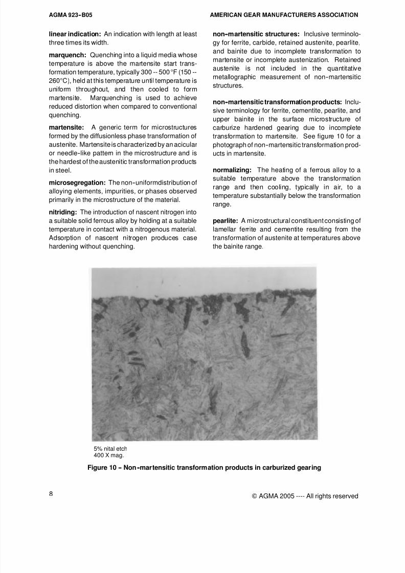
non--martensitic transformation products: Inclu-sive terminology for ferrite, cementite, pearlite, and
upper bainite in the surface microstructure of
carburize hardened gearing due to incomplete
transformation to martensite. See figure 10 for a
photograph of non--martensitic transformation prod-
ucts in martensite.
normalizing: The heating of a ferrous alloy to a
suitable temperature above the transformation
range and then cooling, typically in air, to a
temperature substantially below the transformation
range.
pearlite: A microstructural constituent consisting of
lamellar ferrite and cementite resulting from the
transformation of austenite at temperatures above
the bainite range.
5% nital etch400 X mag.
Figure 10 -- Non --martensitic transformation products in carburized gearing
8/15/2019 AGMA 923-B05
http://slidepdf.com/reader/full/agma-923-b05 15/39
AGMA 923--B05AMERICAN GEAR MANUFACTURERS ASSOCIATION
9
© AGMA 2005 ---- All rights reserved
pitting resistance: Endurance limit adequate to
resist contact fatigue. Initial pitting and progressive
pitting are illustrated and discussed in ANSI/AGMA
1010--E95. See standards such as ANSI/AGMA
2001--C95, ANSI/AGMA 2003--B97, ANSI/AGMA
6002--B93, or ANSI/AGMA 6032--A94.
process control test coupon: For carburize and
hardened gearing or nitrided gearing, a test couponused primarily to monitor the consistency of the heat
treatment process in terms of carbon or nitrogen
penetration and case microstructure. Sometimes
called a standardized test coupon. For procedures
associated with process control test coupons, see
4.2.1.
Due to differences in quench cooling rates and
hardenability, the microstructure and hardness of
process control test coupons used for carburize and
hardened gearingmay not be the same as that ofthe
finished gear tooth.
reduction ratio: In forging and rolling, the ratio of
the cross sectional area of the rough cast ingot or
continuously cast billet to the final cross--sectional
area. The reduction ratio is calculated by the
following equation:
RR = A
B
C
D
E
G
F
H (1)
where
RR is reduction ratio;
A is the cross sectional area of the cast ingot
or continuous cast billet, in2 (mm2).
For bar stock and forged shafting including step
shafts for solid on shaft pinion blanks as in figure 5:
B is the cross sectional area at the finished
largest forging diameter in the area where
the teeth will be, in2 (mm2); and,
C, D, E, F, G and H = 1.
For upset forged gearing blanks as in figures 7 and 8:
B is the cross sectional area of the billet prior
to upsetting, in2 (mm2);
C is the height of the cutoffingot prior to upset-
ting, inch (mm);
D is the height of the finish forged upset blank
before piercing, inch (mm); and
E, F, G and H = 1.
For forged or rolled rings:
B is the cross sectional area of the billet prior
to upsetting, in2 (mm2);
C is the height of the cutoffingot prior to upset-
ting, inch (mm);
D is the height of the upset blank after upset-
ting before piercing, inch (mm);
E is theheightof theupsetblank after piercing,inch (mm);
F is the wall thickness of the upset blank after
piercing, before any bore expansion
associated with piercing, inch (mm);
G isthe heightof the finish forged orrolledring,
inch (mm);
H is the wall thickness of the finish forged or
rolled ring, inch (mm).
representative test coupon: A test coupon de-
signed to represent the quenching rate of the
finished gearing tooth. If the coupon is to be usedonly to determine the case properties, it can be
smaller than one used to determine the core
properties of the gear tooth. A representative test
coupon sized for determining the core hardness and
microstructure can also be used for determining the
case properties or as a process control test coupon.
A representative test coupon sized for determining
the case properties can also be used as a process
control test coupon but not for determining core
properties unless substantiated by documented test
data. For procedures associated with representative
test coupons, see 4.2.2.
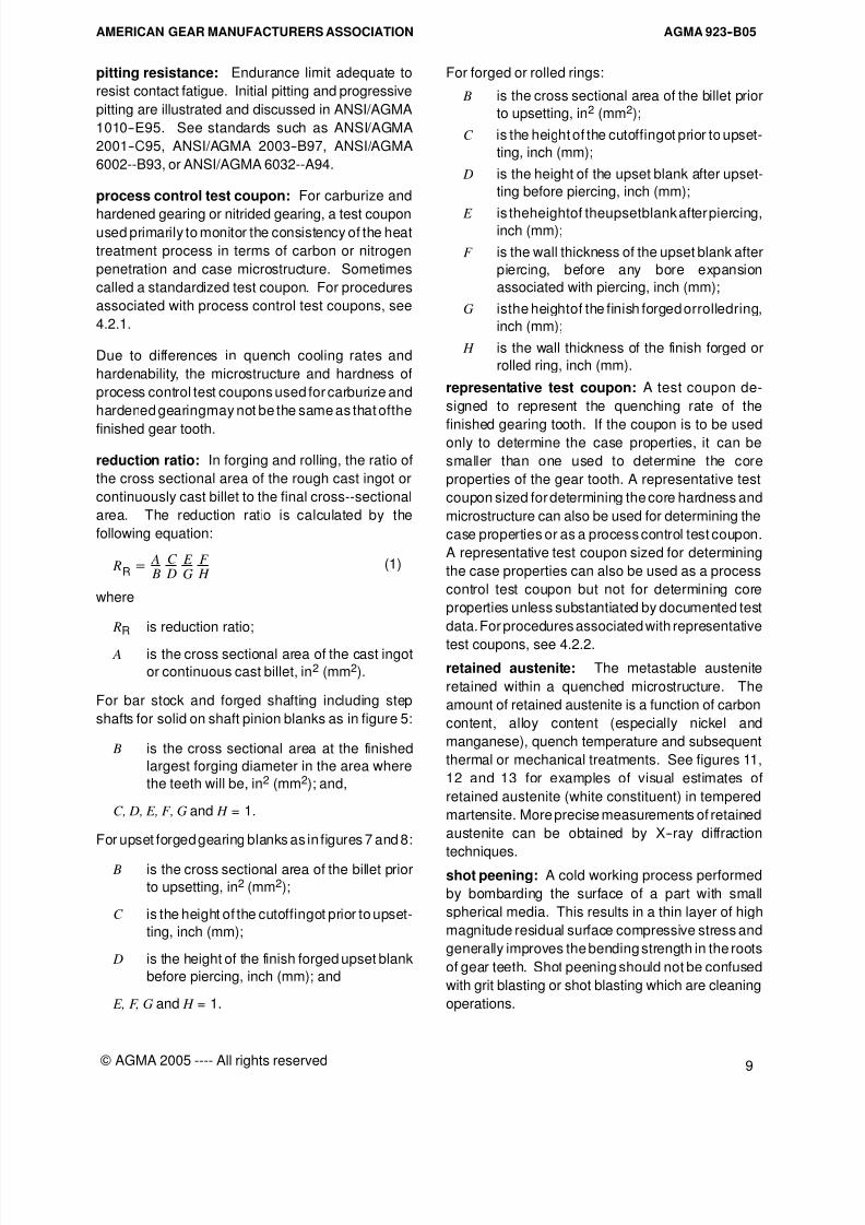
retained austenite: The metastable austenite
retained within a quenched microstructure. The
amount of retained austenite is a function of carbon
content, alloy content (especially nickel and
manganese), quench temperature and subsequent
thermal or mechanical treatments. See figures 11,
12 and 13 for examples of visual estimates of
retained austenite (white constituent) in tempered
martensite. More precise measurements of retained
austenite can be obtained by X--ray diffraction
techniques.shot peening: A cold working process performed
by bombarding the surface of a part with small
spherical media. This results in a thin layer of high
magnitude residual surface compressive stress and
generally improves the bending strength in the roots
of gear teeth. Shot peening should not be confused
with grit blasting or shot blasting which are cleaning
operations.
8/15/2019 AGMA 923-B05
http://slidepdf.com/reader/full/agma-923-b05 16/39
AGMA 923--B05 AMERICAN GEAR MANUFACTURERS ASSOCIATION
10 © AGMA 2005 ---- All rights reserved
5% nital etch 400X mag.
Figure 11 -- Tempered martensite and 5%
retained austenite in carburized gearing
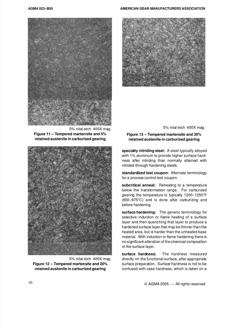
5% nital etch 400X mag.
Figure 12 -- Tempered martensite and 20%
retained austenite in carburized gearing
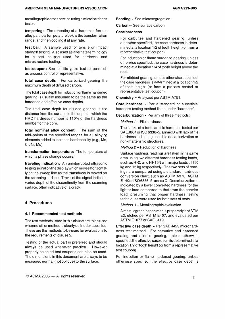
5% nital etch 400X mag.
Figure 13 -- Tempered martensite and 30%
retained austenite in carburized gearing
specialty nitriding steel: A steel typically alloyed
with 1% aluminum to provide higher surface hard-
ness after nitriding than normally attained with
nitrided through hardening steels.
standardized test coupon: Alternate terminologyfor a process control test coupon.
subcritical anneal: Reheating to a temperature
below the transformation range. For carburized
gearing the temperature is typically 1200--1250°F
(650--675°C) and is done after carburizing and
before hardening.
surface hardening: The generic terminology for
selective induction or flame heating of a surface
layer and then quenching that layer to produce a
hardened surface layer that may be thinner than the
heated area, but is harder than the unheated base
material. With induction or flame hardening there is
no significant alteration of the chemical composition
of the surface layer.
surface hardness: The hardness measured
directly on the functional surface, after appropriate
surface preparation. Surface hardness is not to be
confused with case hardness, which is taken on a
8/15/2019 AGMA 923-B05
http://slidepdf.com/reader/full/agma-923-b05 17/39
AGMA 923--B05AMERICAN GEAR MANUFACTURERS ASSOCIATION
11
© AGMA 2005 ---- All rights reserved
metallographic cross section using a microhardness
tester.
tempering: The reheating of a hardened ferrous
alloy part to a temperature below the transformation
range, and then cooling it at any rate.
test bar: A sample used for tensile or impact
strength testing. Also used as alternate terminology
for a test coupon used for hardness andmicrostructure testing.
test coupon: See specific type of test coupon such
as process control or representative.
total case depth: For carburized gearing the
maximum depth of diffused carbon.
The total case depth for induction or flame hardened
gearing is usually assumed to be the same as the
hardened and effective case depths.
The total case depth for nitrided gearing is the
distance from the surface to the depth at which the
HRC hardness number is 110% of the hardness
number for the core.
total nominal alloy content: The sum of the
mid--points of the specified ranges for all alloying
elements added to increase hardenability (e.g., Mn,
Cr, Ni, Mo).
transformation temperature: The temperature at
which a phase change occurs.
traveling indication: An uninterrupted ultrasonic
testing signal on the displaywhich moves horizontal-ly on the sweep line as the transducer is moved on
the scanning surface. Travel of the signal indicates
varied depth of the discontinuity from the scanning
surface, often indicative of a crack.
4 Procedures
4.1 Recommended test methods
The test methods listed in this clause are to be used
whenno other method is clearly definedor specified.
These are the methods to be used for evaluations to
the requirements of clause 5.
Testing of the actual part is preferred and should
always be used whenever practical. However,
properly selected test coupons can also be used.
The dimensions in this document are always to be
measured normal (not oblique) to the surface.
Banding -- See microsegregation.
Carbon -- See surface carbon.
Case hardness
For carburize and hardened gearing, unless
otherwise specified, the case hardness is deter-
mined at a location 1/2 of tooth height (or from a
representative test coupon).
For induction or flame hardened gearing, unless
otherwise specified, the case hardness is deter-
mined at a location 1/4 of tooth height above the
root.
For nitrided gearing, unless otherwise specified,
the case hardness is determined at a location 1/2
of tooth height (or from a process control or
representative test coupon).
Chemistry -- Analyzed per ASTM A751.
Core hardness -- Per a standard or superficial
hardness testing method listed under “hardness”.
Decarburization -- Per any of three methods:
Method 1 -- File hardness
The flanks of a tooth are file hardness tested per
SAEJ864 or ISO 6336--5, annex D with lack of file
hardness indicating possible decarburization or
non--martensitic structures.
Method 2 -- Reduction of hardness
Surface hardness readings are taken in the same
area using two different hardness testing loads,
such as HRC and HR15N with major loads of 150
kg and 15 kg respectively. The two sets of read-ings are compared using a standard hardness
conversion chart, such as ASTM A370, ASTM
E140or ISO 6336--5, annex C. Decarburization is
indicated by a lower converted hardness for the
lighter load compared to that from the heavier
load, presuming that proper hardness testing
techniques were used for both sets of tests.
Method 3 -- Metallographic evaluation
A metallographicspecimenis prepared perASTM
E3, etched per ASTM E407, and evaluated per
ASTM E1077 or SAE J419.
Effective case depth -- Per SAE J423 microhard-
ness test method. For carburize and hardened
gearing and nitrided gearing, unless otherwise
specified, the effective case depth is determined at a
location 1/2 of tooth height (or from a representative
test coupon).
For induction or flame hardened gearing, unless
otherwise specified, the effective case depth is
8/15/2019 AGMA 923-B05
http://slidepdf.com/reader/full/agma-923-b05 18/39
AGMA 923--B05 AMERICAN GEAR MANUFACTURERS ASSOCIATION
12 © AGMA 2005 ---- All rights reserved
determinedat a location 1/4of tooth heightabove the
root.
Grain size -- Per ASTM E112 or ISO 643.
Hardenability -- Per ASTM A255 or ISO 642
end--quench test or by hardenability calculation per
ASTM A255.
Hardness -- Listed below are each method and theassociated processes which are tested by that
method.
ASTM E10, Brinell hardness testing
-- Through hardened parts
-- Base hardness of flame, induction, or nitride
hardened parts
ASTM E18, Rockwell hardness testing
-- Through hardened parts
-- Carburize and hardened parts
-- Flame and induction hardened parts
-- Nitrided parts
ASTM E92, Vicker’s hardness testing
-- Through hardened parts
-- Carburize and hardened parts
-- Flame and induction hardened parts
-- Nitrided parts
ASTM E384, Microhardness testing
-- Carburize and hardened parts
-- Flame and induction hardened parts
-- Nitrided parts
If standard bench top hardness testing cannot be
accomplished as stated in ASTM E10 or ASTM E18,
portable testing may be accomplished by ASTM
E110 or other appropriate methods.
Measurement of surface hardness per ASTM E18 is
used as a nondestructive method to evaluate the
conformity of individual work pieces to the surface
hardness requirements. The measurement method
should be appropriate for the size and configuration
of the work pieces. The teeth area requirements for
hardness measurements include the root of the
tooth. Alternate methods of hardness measure-
ment, including file testing in accordance with SAE
J864 or ISO 6336--5, annex D, may be used.
Dueto the state of the art of alternate microhardness
testing methods, results may vary by the equivalent
of three pointsHRC from actual HRC measurements
per ASTM E18. The significance and interpretation
of those results needs to be agreed upon between
the parties.
Intergranular oxides -- In the unetched condition,
see metallography and figure 9.
Magnetic particle -- Per ASTM E1444 regardless of
form, or alternatively ASTM E125 for raw castings,ASTM A275 for raw forgings, or ASTM E709 for
finished gearing.
Mechanical testing -- Per ASTM E8 for tensile
testing and ASTM E23 for impact testing (also see
hardness).
Metallography -- Performed at a magnification of
400 -- 600 diameters. Metallographic samples shall
be prepared per ASTM E3 and etched per ASTM
E407, except for intergranular oxidation which shall
be evaluated in the unetched condition.
Microhardness -- See hardness.
Microsegregation -- Analyzed per ASTM A534.
Acceptance criteria is not specified but is to be
agreed upon.
Microstructure -- See metallography.
Nonmetallic inclusions -- Per any of the following
methods:
-- SAE/AMS 2301, for aircraft steels
-- ASTM A534, for carburizing bearing steels
-- ASTM A866, for through hardening bearing
steels
-- ASTM E45, for inclusion count
-- ISO 4967, by comparison to micrographic
diagrams, Method B, Plate II with 0.3 in2 (200
mm2) inspection area
-- SAE J422, by comparison to micrographic
diagrams
Surface carbon -- Perone of the following methods:
Method 1 -- Spectrometric
Per ASTM E415.
Method 2 -- Combustion
The combustion method utilizes chips from a ma-
chiningcut of 0.001 -- 0.004 inch (0.02 -- 0.10 mm)
in thickness on a carbon control specimen. The
chips from this cut are collected and analyzed by
combustion for carbon content per ASTM E350.
The specimen should be machined dry with high
8/15/2019 AGMA 923-B05
http://slidepdf.com/reader/full/agma-923-b05 19/39
AGMA 923--B05AMERICAN GEAR MANUFACTURERS ASSOCIATION
13
© AGMA 2005 ---- All rights reserved
speed cutting tools on centers, and at least one
gram of clean chips free of contamination should
be used for analysis.
Both methods require that prior to carburizing the
process control specimen, sufficient stock be ma-
chined from the surface to be carburized, in order
to remove all material with non--uniform surface
chemistry.
Surface temper -- Per ANSI/AGMA 2007--B92 or
ISO 14104.
Test coupons -- Microstructure, microhardness and
core hardness characteristics may be determined
from either actual parts or test coupons. See 4.2 for
the specific type of test coupon (process control or
representative).
Ultrasonic inspection -- Ultrasonic inspection is
recommended for large parts to detect flaws before
incurring the expense of machining. When ultrason-
ic inspection is specified, the following guidelinesshall apply:
-- For wrought products the straight beam pro-
cedures described in ASTM A388 shall apply. Ei-
ther the flat bottom hole or back reflection method
may be used.
The sensitivity for the flat bottom hole method
shall utilize standard test blocks per ASTM E428
with the reflector size as specified in tables 1
through4 of this information sheet. The metal test
distance for the blocks shall be 4.000 inches
(101.6 mm). This sensitivity shall be used whenradially scanning the portion of the wrought mate-
rial that will comprise the tooth area. The tooth
area includes only those portions of the gearing
material where the teeth will be located to a depth
below the finished tooth tips of at least 1.5 times
the tooth height. The balance of the part may be
scanned using a distance amplitude correction
curve (DAC) whose construction is detailed in
ASTM A388.
-- For cast products the straight beam proce-
dures described in ASTM A609 shall apply. The
back reflection method shall be used.
4.2 Test coupons
4.2.1 Process control test coupons
Process control test coupons are used to monitor
various heat treatment process parameters, their
variation, their interactions, and to verify that these
parameters are maintained within their expected
control range. The process control test coupons
may be made of varioussteel grades, differentsizes,
and differing geometry depending on the parameter
to be monitored and the heat treat facility’s quality
control plan. Process control test coupons are not
intended to be used for final acceptance.
The properties of a process control coupon may be
correlated by experience to the properties of thefinished gearing with regard to hardness and case
depth. The process control test coupon
microstructure may be correlated to the condition of
the finished gear. The method of correlation should
be documented.
Process control test coupons may be used to
determine surface carbon concentration, carbon
penetration, carbon gradients, nitride depth, white
layer thickness, intergranular oxidation depth, and
process repeatability. Shim stock is often used to
monitor atmospheric carbon potential. Variations
from expected process control limits are used asindicators of unacceptable heat treat process varia-
tions. As long as the process control test coupons
are within expected control limits, the parts being
heat treated should have the expected metallurgical
properties.
The process control test coupon for carburize and
hardening should have minimum dimensions of 5/8
inch (16 mm) diameter by 2 inches (50 mm) long and
is suitable for gearing 4.5 normal diametral pitch (5.6
module) and finer. A 1 inch (25 mm) diameter by 2
inches (50 mm) long coupon may be used for
coarser pitch (module) carburized gearing to 1.5
normal diametral pitch (17 mm module). The size of
the coupon for coarser than 1.5 normal diametral
pitch (17 module) gearing should be agreed upon,
and should approximate the inscribed diameter at
mid height of the tooth cross section. The coupon
length should be a minimum of 2 times the diameter.
Test disks or plates may be used whose minimum
thickness is 70 percent of the appropriate test bar
diameter. The minimum inscribed diameter on a test
disc (or plate dimensions) should be three times its
thickness.
For determination of case hardness, case depth,
and case microstructure, the process control test
coupon should be examined on a section normal to
its axis and at least one diameter from the end of the
test coupon. Case hardness is to be measured by a
microhardness method at a depth 0.002 to 0.004
inch (0.05 to 0.10 mm) below the surface. Any
post--heat treat stock removal must be considered.
8/15/2019 AGMA 923-B05
http://slidepdf.com/reader/full/agma-923-b05 20/39
AGMA 923--B05 AMERICAN GEAR MANUFACTURERS ASSOCIATION
14 © AGMA 2005 ---- All rights reserved
4.2.2 Representative test coupon
The representative test coupon shall be from the
same grade of alloy steel with similar hardenability
as the production part, but need not necessarily be
from the same heat of steel. Representative test
coupon proportions of a minimum diameter of 6
divided by the normal diametral pitch (6 times
module)but not less than 5/8 inch diameter (16 mm),
and a minimum length 2 times its diameter, as used
in ISO 6336--5, are recommended. A representative
test coupon may contain a tooth form that will be
used to verify the heat treat process.
With customer approval, representative test coupon
proportions of a minimum diameter of 3 divided by
the normal diametral pitch (3 times module) but not
less than 5/8 inch diameter (16 mm), and a minimum
length 2 times its diameter, as used in ISO 6336--5,
are recommended.
A representative test coupon should have the same
heattreat condition prior to carburizing as the part(s)represented. This coupon should remain with the
part(s) represented throughout the entire heat treat
process, with the possible exception of heat
treatments prior to carburizing.
The representative test coupon, when positioned in
a heat treat load in the same general area but
separate from thepiece part, is intended to represent
the metallurgy of the heat treated tooth section. The
microstructure at the center of the minimum size
representative test coupon approximates the core
microstructure of the tooth section.
5 Metallurgical requirements
The metallurgical characteristics identified in the
tables of this clause are intended to be used for all
steel gearing. Metallurgical characteristics defined
in the tables of this clause are intended to assure the
quality of the finished gear teeth.
Individual AGMA rating standards may have specific
modifications to the metallurgical characteristics
grading; but the intent is to formalize the assump-
tions and definitions on which the various AGMA
standards are based. These characteristics should
be compatible, wherever possible, with ISO 6336--5.
Users of this document must be aware that the
Grade 1, Grade 2 and Grade 3 gearing produced by
different heat treatment processes have different
ratings. Refer to the applicable gear rating
standards for specific gear ratings.
Individual customers and manufacturers may have
specific modifications to the metallurgical grade
requirements or special material and processing
conditions that are not covered in these tables.
These modifications and special conditions are
permissible with mutual agreement.
The following tables establish reasonable minimum
limits for each material and metallurgical character-
istic that will allow gearing, which meet dimensional
tolerances, to meet the minimum expectations of the
gear rating design standards. As individual gearing
designs increase in size and complexity of features,
they become more difficult to manufacture, heat
treat, and inspect. This document, as a general rule,
does not differentiate based on gearing size.
However, where necessary, specific notation is
made to reflect the special processing methods,
techniques and inspections required for large gear
manufacturing.
All requirements for a metallurgical quality grade
must be met in order to use the stress value, from the
AGMA rating standard, for that grade. This can be
accomplished by specifically certifying each require-
ment where necessary, or by establishing practices
and procedures to obtain the requirements on a
production basis. It is not the intent of this document
that all requirements for metallurgical quality grade
be certified, but that practices and procedures be
established for their compliance on a production
basis. Intermediate values are not classified since
the effect of deviations from the quality standardscannot be evaluated easily. Specific sampling plans
and test methods need to be addressed by either the
manufacturer, the customer, or both.
The various characteristics are listed in the order in
which that characteristic is typically evaluated during
the manufacturing sequence. Each individual
characteristic has the same item number in tables 1,
2, 3 and 4 whenever it is used, regardless of which
table it appears. Some characteristics are only
applicable to specific heat treat methods. Therefore,
some item numbers are not used in some tables.
Characteristics that are typically evaluated at the
same time are grouped by having the same number
before the decimal point, and modified with different
numbers after the decimal point for the individual
characteristics evaluated at that time.
5.1 Through hardened gearing
The major metallurgical characteristics that affect
through hardened gearing performance are shown
8/15/2019 AGMA 923-B05
http://slidepdf.com/reader/full/agma-923-b05 21/39
AGMA 923--B05AMERICAN GEAR MANUFACTURERS ASSOCIATION
15
© AGMA 2005 ---- All rights reserved
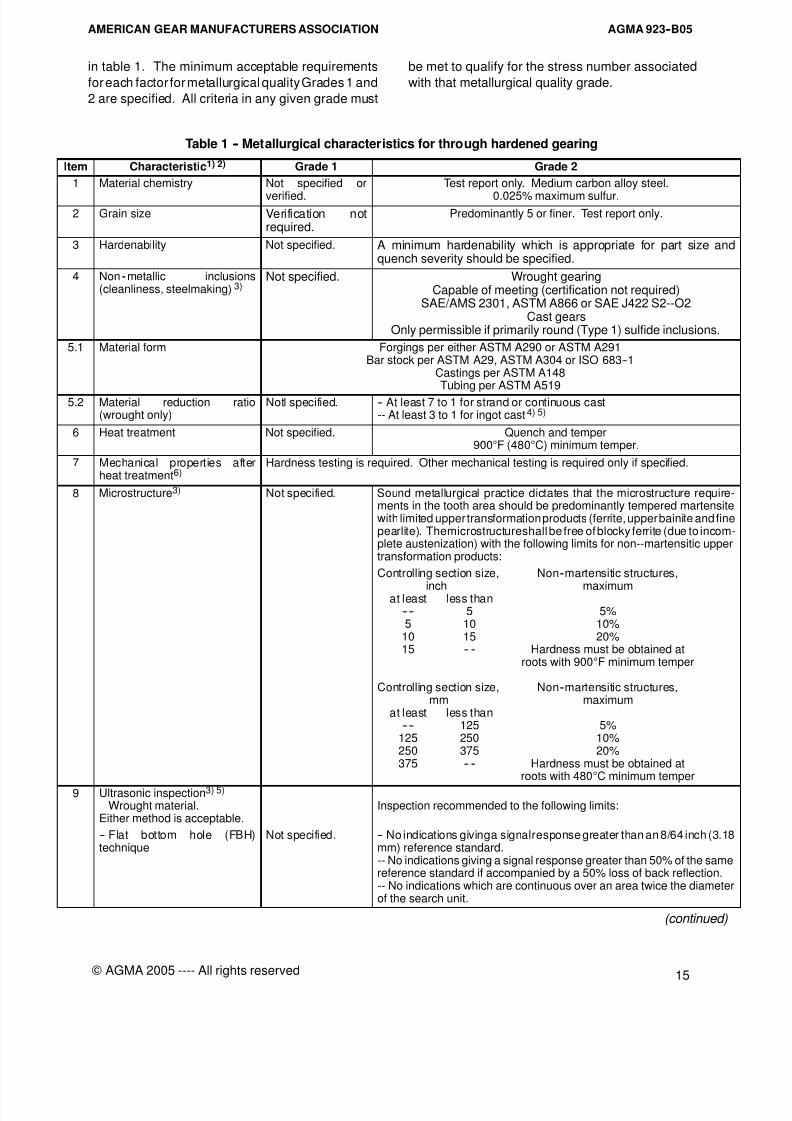
in table 1. The minimum acceptable requirements
for each factor for metallurgical quality Grades 1 and
2 are specified. All criteria in any given grade must
be met to qualify for the stress number associated
with that metallurgical quality grade.
Table 1 -- Metallurgical characteristics for through hardened gearing
Item Characteristic1) 2) Grade 1 Grade 2
1 Material chemistry Not specified or
verified.
Test report only. Medium carbon alloy steel.
0.025% maximum sulfur.2 Grain size Verification not
required.Predominantly 5 or finer. Test report only.
3 Hardenability Not specified. A minimum hardenability which is appropriate for part size andquench severity should be specified.
4 Non--metallic inclusions(cleanliness, steelmaking) 3)
Not specified. Wrought gearingCapable of meeting (certification not required)
SAE/AMS 2301, ASTM A866 or SAE J422 S2--O2Cast gears
Only permissible if primarily round (Type 1) sulfide inclusions.
5.1 Material form Forgings per either ASTM A290 or ASTM A291Bar stock per ASTM A29, ASTM A304 or ISO 683--1
Castings per ASTM A148Tubing per ASTM A519
5.2 Material reduction ratio(wrought only)
Notl specified. -- At least 7 to 1 for strand or continuous cast-- At least 3 to 1 for ingot cast4) 5)
6 Heat treatment Not specified. Quench and temper900°F (480°C) minimum temper.
7 Mechanical properties afterheat treatment6)
Hardness testing is required. Other mechanical testing is required only if specified.
8 Microstructure3) Not specified. Sound metallurgical practice dictates that the microstructure require-ments in the tooth area should be predominantly tempered martensitewith limited upper transformation products (ferrite, upper bainite and finepearlite). Themicrostructureshall be free of blocky ferrite (due to incom-plete austenization) with the following limits for non--martensitic uppertransformation products:
Controlling section size, Non--martensitic structures,
inch maximumat least less than---- 5 5%5 10 10%
10 15 20%15 -- -- Hardness must be obtained at
roots with 900°F minimum temper
Controlling section size, Non--martensitic structures,mm maximum
at least less than---- 125 5%
125 250 10%250 375 20%375 -- -- Hardness must be obtained at
roots with 480°C minimum temper
9 Ultrasonic inspection3) 5)
Wrought material.Either method is acceptable.
Inspection recommended to the following limits:
-- Flat bottom hole (FBH)technique
Not specified. -- No indications givinga signalresponse greater than an 8/64 inch (3.18mm) reference standard.-- No indications giving a signal response greater than 50% of the samereference standard if accompanied by a 50% loss of back reflection.-- No indications which are continuous over an area twice the diameterof the search unit.
(continued)
8/15/2019 AGMA 923-B05
http://slidepdf.com/reader/full/agma-923-b05 22/39
AGMA 923--B05 AMERICAN GEAR MANUFACTURERS ASSOCIATION
16 © AGMA 2005 ---- All rights reserved
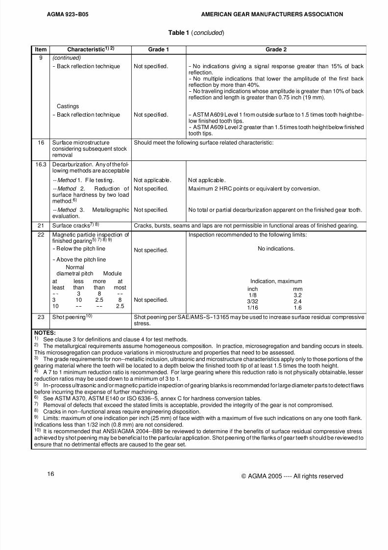
Table 1 (concluded )
Item Characteristic1) 2) Grade 1 Grade 2
9 (continued)
-- Back reflection technique Not specified. -- No indications giving a signal response greater than 15% of backreflection.-- No multiple indications that lower the amplitude of the first backreflection by more than 40%.-- No traveling indications whose amplitude is greater than 10% of back
reflection and length is greater than 0.75 inch (19 mm).
Castings
-- Back reflection technique Not specified. -- ASTM A609 Level 1 from outside surface to 1.5 times tooth heightbelow finished tooth tips.-- ASTM A609 Level 2 greater than 1.5 times tooth height below finishedtooth tips.
16 Surface microstructureconsidering subsequent stockremoval
Should meet the following surface related characteristic:
16.3 Decarburization. Any of the fol-lowing methods are acceptable
-- Method 1. File testing. Not applicable. Not applicable.
-- Method 2. Reduction ofsurface hardness by two loadmethod.6)
Not specified. Maximum 2 HRC points or equivalent by conversion.
-- Method 3. Metallographicevaluation.
Not specified. No total or partial decarburization apparent on the finished gear tooth.
21 Surface cracks7) 8) Cracks, bursts, seams and laps are not permissible in functional areas of finished gearing.
22 Magnetic particle inspection offinished gearing5) 7) 8) 9)
-- Below the pitch line Not specified.
Inspection recommended to the following limits:
No indications.
-- Above the pitch line
Normaldiametral pitch Module
at less more at
least than than most---- 3 8 ----3 10 2.5 810 ---- ---- 2.5
Not specified.
Indication, maximum
inch mm1/8 3.2
3/32 2.41/16 1.6
23 Shot peening10) Shot peening per SAE/AMS--S--13165 may be used to increase surface residual compressivestress.
NOTES:1) See clause 3 for definitions and clause 4 for test methods.2) The metallurgical requirements assume homogeneous composition. In practice, microsegregation and banding occurs in steelsThis microsegregation can produce variations in microstructure and properties that need to be assessed.3) The grade requirements for non--metallic inclusion, ultrasonic and microstructure characteristics apply only to those portions of thegearing material where the teeth will be located to a depth below the finished tooth tip of at least 1.5 times the tooth height.4) A 7 to 1 minimum reduction ratio is recommended. For large gearing where this reduction ratio is not physically obtainable, lesserreduction ratios may be used down to a minimum of 3 to 1.
5) In--process ultrasonic and/or magnetic particle inspection of gearing blanks is recommended for large diameter parts to detect flawsbefore incurring the expense of further machining.6) See ASTM A370, ASTM E140 or ISO 6336--5, annex C for hardness conversion tables.7) Removal of defects that exceed the stated limits is acceptable, provided the integrity of the gear is not compromised.8) Cracks in non--functional areas require engineering disposition.9) Limits: maximum of one indication per inch (25 mm) of face width with a maximum of five such indications on any one tooth flank.Indications less than 1/32 inch (0.8 mm) are not considered.10) It is recommended that ANSI/AGMA 2004--B89 be reviewed to determine if the benefits of surface residual compressive stressachieved by shot peening may be beneficial to the particular application. Shot peening of the flanks of gear teeth should be reviewed toensure that no detrimental effects are caused to the gear set.
8/15/2019 AGMA 923-B05
http://slidepdf.com/reader/full/agma-923-b05 23/39
AGMA 923--B05AMERICAN GEAR MANUFACTURERS ASSOCIATION
17
© AGMA 2005 ---- All rights reserved
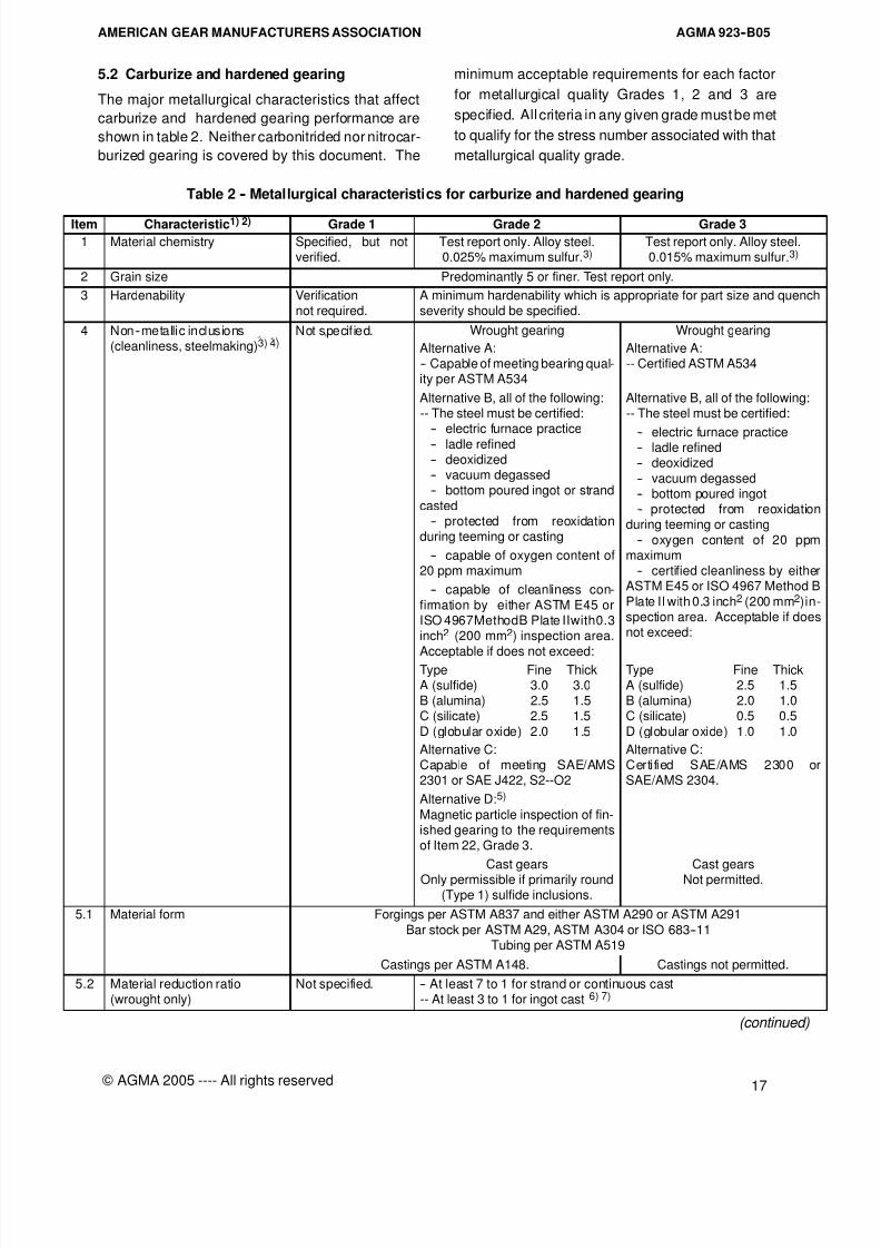
5.2 Carburize and hardened gearing
The major metallurgical characteristics that affect
carburize and hardened gearing performance are
shown in table 2. Neither carbonitrided nor nitrocar-
burized gearing is covered by this document. The
minimum acceptable requirements for each factor
for metallurgical quality Grades 1, 2 and 3 are
specified. All criteria in any given grade must be met
to qualify for the stress number associated with that
metallurgical quality grade.
Table 2 -- Metallurgical characteristics for carburize and hardened gearing
Item Characteristic1) 2) Grade 1 Grade 2 Grade 3
1 Material chemistry Specified, but notverified.
Test report only. Alloy steel.0.025% maximum sulfur.3)
Test report only. Alloy steel.0.015% maximum sulfur.3)
2 Grain size Predominantly 5 or finer. Test report only.
3 Hardenability Verificationnot required.
A minimum hardenability which is appropriate for part size and quenchseverity should be specified.
4 Non--metallic inclusions Not specif ied. Wrought gearing Wrought gearing
(cleanliness, steelmaking)3) 4) Alternative A:-- Capable of meeting bearing qual-ity per ASTM A534
Alternative B, all of the following:-- The steel must be certified:
-- electric furnace practice
-- ladle refined-- deoxidized-- vacuum degassed-- bottom poured ingot or strand
casted-- protected from reoxidation
during teeming or casting
-- capable of oxygen content of20 ppm maximum
-- capable of cleanliness con-
firmation by either ASTM E45 orISO 4967MethodB Plate IIwith0.3inch2 (200 mm2) inspection area.
Acceptable if does not exceed:
Alternative A:-- Certified ASTM A534
Alternative B, all of the following:-- The steel must be certified:
-- electric furnace practice-- ladle refined-- deoxidized
-- vacuum degassed-- bottom poured ingot-- protected from reoxidation
during teeming or casting
-- oxygen content of 20 ppmmaximum
-- certified cleanliness by eitherASTM E45 or ISO 4967 Method B
Plate II with 0.3 inch2 (200 mm2)in-spection area. Acceptable if doesnot exceed:
Type Fine ThickA (sulfide) 3.0 3.0B (alumina) 2.5 1.5C (silicate) 2.5 1.5
D (globular oxide) 2.0 1.5
Type Fine ThickA (sulfide) 2.5 1.5B (alumina) 2.0 1.0C (silicate) 0.5 0.5
D (globular oxide) 1.0 1.0
Alternative C:Capable of meeting SAE/AMS2301 or SAE J422, S2--O2
Alternative D:5)
Magnetic particle inspection of fin-ished gearing to the requirementsof Item 22, Grade 3.
Alternative C:Certified SAE/AMS 2300 orSAE/AMS 2304.
Cast gears
Only permissible if primarily round(Type 1) sulfide inclusions.
Cast gears
Not permitted.
5.1 Material form Forgings per ASTM A837 and either ASTM A290 or ASTM A291
Bar stock per ASTM A29, ASTM A304 or ISO 683--11Tubing per ASTM A519
Castings per ASTM A148. Castings not permitted.
5.2 Material reduction ratio(wrought only)
Not specified. -- At least 7 to 1 for strand or continuous cast-- At least 3 to 1 for ingot cast 6) 7)
(continued)

8/15/2019 AGMA 923-B05
http://slidepdf.com/reader/full/agma-923-b05 24/39
AGMA 923--B05 AMERICAN GEAR MANUFACTURERS ASSOCIATION
18 © AGMA 2005 ---- All rights reserved
Table 2 (continued )
Item Characteristic1) 2) Grade 1 Grade 2 Grade 3
9 Ultrasonic inspection4) 7)
Wrought material.Either method is acceptable.
Inspection recommended to thefollowing limits:
Inspection required to the followinlimits:
-- Flat bottom hole (FBH)technique
Not specified. -- No indications giving a signal re-sponse greater than an 8/64 inch(3.18 mm) reference standard.
-- No indications giving a signalresponse greater than 50% of thereference standard if accompaniedby a 50% loss of back reflection.-- No indications which arecontinuous over an area twice thediameter of the search unit.
-- No indications giving a signal response greater than a 5/64 inch(1.98 mm) reference standard.
-- No indications giving a signal response greater than 50%of thereference standard if accompanied ba 50% loss of back reflection.-- No indications which are continuousover an area twice thediameteof the search unit.
-- Back reflection technique Not specified. -- No indications giving a signal re-sponse greater than 15% of backreflection.-- No multiple indications that lowerthe amplitude of the first back re-flection by more than 40%.-- No traveling indications whoseamplitude is greater than 10% of
back reflection and length is great-er than 0.75 inch (19 mm).
-- No indications giving a signal response greater than 10% of bacreflection.-- No multiple indications that lowethe amplitude of the first back reflection by more than 20%.-- No traveling indications whosamplitude is greater than 10% o
back reflection and length is greater than 0.50 inch (13 mm).
Castings
-- Back reflection technique Not specified. -- ASTM A609 Level 1 from outsidesurface to 1.5 times tooth heightbelow finished tooth tips.-- ASTM A609 Level 2 greater than1.5 times tooth height below fin-ished tooth tips.
11 Tempering after case
hardening
Recommended. Required.
12 Surface hardness in tooth area.Alternative method of inspec-
tion is case hardness.8) 9) 10)
Should meet the following characteristics:
-- Tooth flank 55--64 HRC orequivalent
58--64 HRC or equivalent 58--64 HRC or equivalent
-- Tooth root
-- Normal diametral pitch 3(module 8) and coarser
53 HRC minimum orequivalent
56 HRC minimum or equivalent 58 HRC minimum or equivalent
-- Normal diametral pitchfiner than 3 (module 8)
55 HRC minimum orequivalent
58 HRC minimum or equivalent 58 HRC minimum or equivalent
13 Case depth consideringsubsequent stock removal
Should meet the following characteristics:
13.1 Effective case depth in finishedcondition 10) 11)
Minimum and maximum effective case depth requirements for the tooth should be specified inaccordance with the appropriate rating standard.
13.2 Effective case depth minimumat root radius, as determined bybending strength rating.10) 11)
12)
Not specified. 50% ofminimum specified effectivecase at 1/2 tooth heightrecommended.
66% of minimum specified effectivecase at 1/2 tooth heighrecommended.
14 Core hardness after case hard-ening 12) 13)
-- For pitting resistance rating
-- For bending strength rating
Not specified.
21 HRC minimum
21 HRC minimum
25 HRC minimum
21 HRC minimum
30 HRC minimum14)
(continued)
8/15/2019 AGMA 923-B05
http://slidepdf.com/reader/full/agma-923-b05 25/39
AGMA 923--B05AMERICAN GEAR MANUFACTURERS ASSOCIATION
19
© AGMA 2005 ---- All rights reserved
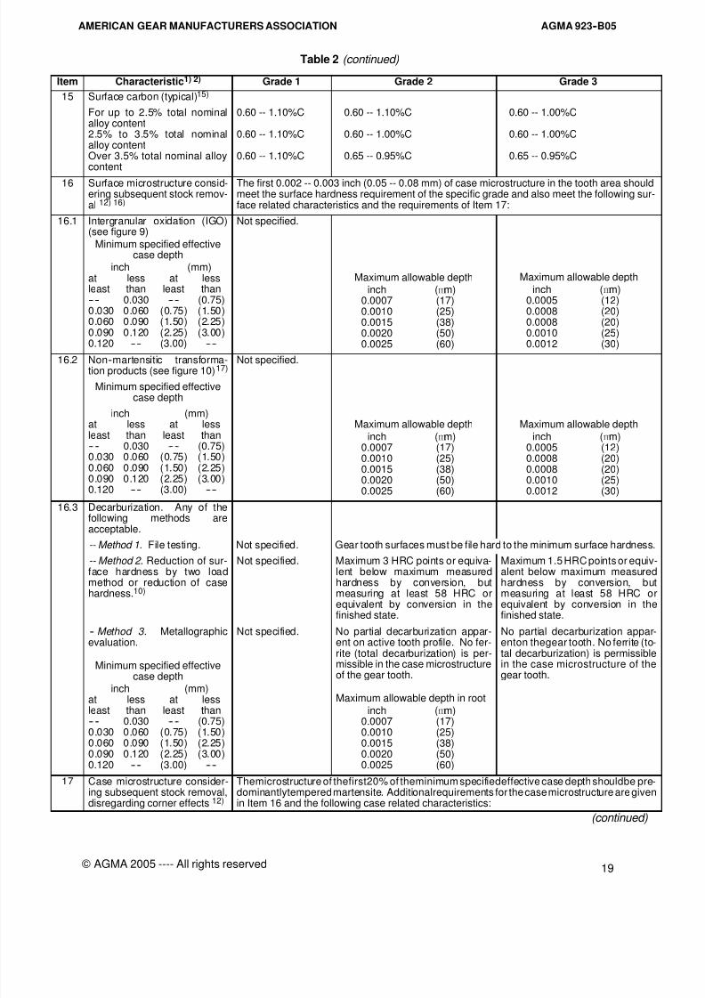
Table 2 (continued)
Item Characteristic1) 2) Grade 1 Grade 2 Grade 3
15 Surface carbon (typical)15)
For up to 2.5% total nominalalloy content2.5% to 3.5% total nominalalloy contentOver 3.5% total nominal alloycontent
0.60 -- 1.10%C
0.60 -- 1.10%C
0.60 -- 1.10%C
0.60 -- 1.10%C
0.60 -- 1.00%C
0.65 -- 0.95%C
0.60 -- 1.00%C
0.60 -- 1.00%C
0.65 -- 0.95%C
16 Surface microstructure consid-ering subsequent stock remov-al 12) 16)
The first 0.002 -- 0.003 inch (0.05 -- 0.08 mm) of case microstructure in the tooth area shouldmeet the surface hardness requirement of the specific grade and also meet the following sur-face related characteristics and the requirements of Item 17:
16.1 Intergranular oxidation (IGO)(see figure 9)
Minimum specified effectivecase depth
inch (mm)at less at lessleast than least than-- -- 0.030 -- -- (0.75)0.030 0.060 (0.75) (1.50)0.060 0.090 (1.50) (2.25)0.090 0.120 (2.25) (3.00)0.120 ---- (3.00) ----
Not specified.
Maximum allowable depthinch (mm)
0.0007 (17)0.0010 (25)0.0015 (38)0.0020 (50)0.0025 (60)
Maximum allowable depth
inch (mm)0.0005 (12)0.0008 (20)0.0008 (20)0.0010 (25)0.0012 (30)
16.2 Non--martensitic transforma-tion products (see figure 10)17)
Not specified.
Minimum specified effectivecase depth
inch (mm)at less at lessleast than least than-- -- 0.030 -- -- (0.75)0.030 0.060 (0.75) (1.50)0.060 0.090 (1.50) (2.25)0.090 0.120 (2.25) (3.00)0.120 ---- (3.00) ----
Maximum allowable depth
inch (mm)0.0007 (17)0.0010 (25)0.0015 (38)0.0020 (50)0.0025 (60)
Maximum allowable depth
inch (mm)0.0005 (12)0.0008 (20)0.0008 (20)0.0010 (25)0.0012 (30)
16.3 Decarburization. Any of thefollowing methods areacceptable.
-- Method 1. File testing. Not specified. Gear tooth surfaces must be file hard to the minimum surface hardness.
-- Method 2 . Reduction of sur-face hardness by two loadmethod or reduction of casehardness.10)
Not specified. Maximum 3 HRC points or equiva-lent below maximum measuredhardness by conversion, butmeasuring at least 58 HRC orequivalent by conversion in thefinished state.
Maximum 1.5 HRC points or equiv-alent below maximum measuredhardness by conversion, butmeasuring at least 58 HRC orequivalent by conversion in thefinished state.
-- Method 3. Metallographicevaluation.
Minimum specified effectivecase depth
inch (mm)
at less at lessleast than least than-- -- 0.030 -- -- (0.75)0.030 0.060 (0.75) (1.50)0.060 0.090 (1.50) (2.25)0.090 0.120 (2.25) (3.00)0.120 ---- (3.00) ----
Not specified. No partial decarburization appar-ent on active tooth profile. No fer-rite (total decarburization) is per-missible in the case microstructureof the gear tooth.
Maximum allowable depth in rootinch (mm)
0.0007 (17)0.0010 (25)0.0015 (38)0.0020 (50)0.0025 (60)
No partial decarburization appar-enton thegear tooth. No ferrite (to-tal decarburization) is permissiblein the case microstructure of thegear tooth.
17 Case microstructure consider-ing subsequent stock removal,disregarding corner effects 12)
Themicrostructure of thefirst20% of theminimum specifiedeffective case depth shouldbe pre-dominantlytempered martensite. Additionalrequirements for the case microstructure are givenin Item 16 and the following case related characteristics:
(continued)
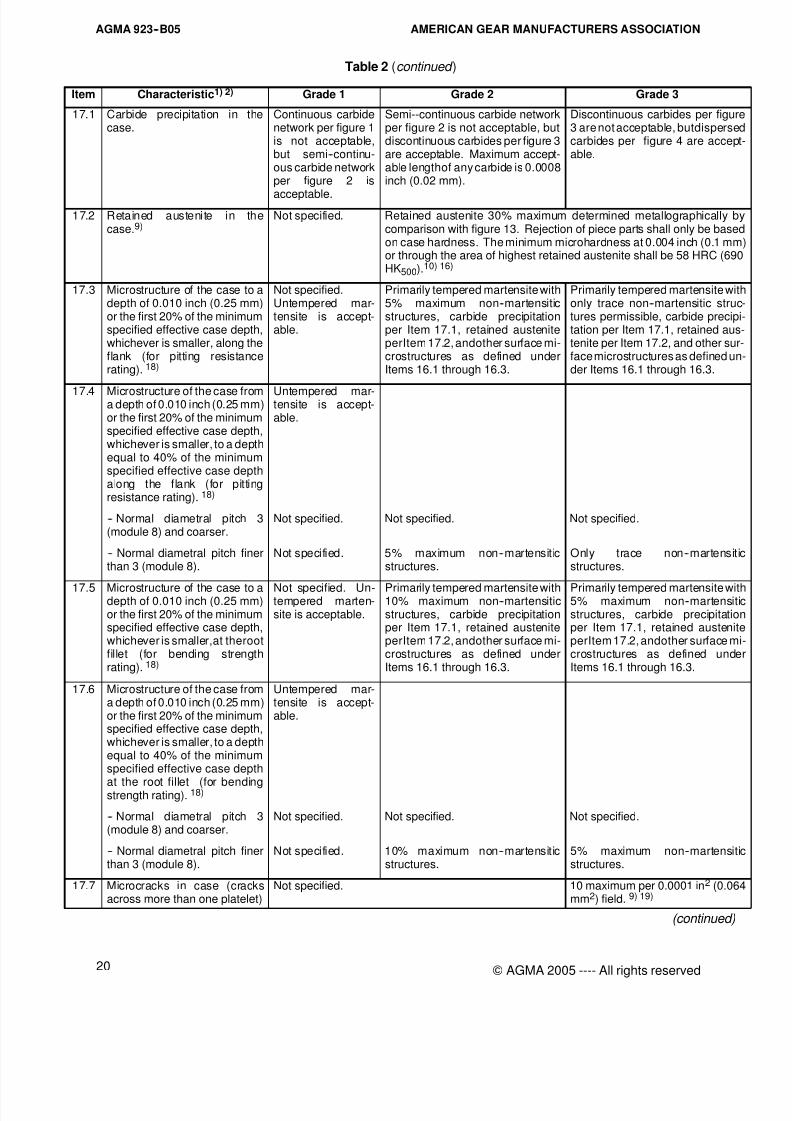
8/15/2019 AGMA 923-B05
http://slidepdf.com/reader/full/agma-923-b05 26/39
AGMA 923--B05 AMERICAN GEAR MANUFACTURERS ASSOCIATION
20 © AGMA 2005 ---- All rights reserved
Table 2 (continued )
Item Characteristic1) 2) Grade 1 Grade 2 Grade 3
17.1 Carbide precipitation in thecase.
Continuous carbidenetwork per figure 1is not acceptable,but semi--continu-ous carbide networkper figure 2 is
acceptable.
Semi--continuous carbide networkper figure 2 is not acceptable, butdiscontinuous carbides per figure 3are acceptable. Maximum accept-able lengthof any carbide is 0.0008inch (0.02 mm).
Discontinuous carbides per figure3 are not acceptable, butdispersedcarbides per figure 4 are acceptable.
17.2 Retained austenite in thecase.9)
Not specified. Retained austenite 30% maximum determined metallographically bcomparison with figure 13. Rejection of piece parts shall only be basedon case hardness. The minimum microhardness at 0.004 inch (0.1 mmor through the area of highest retained austenite shall be 58 HRC (690HK500).10) 16)
17.3 Microstructure of the case to adepth of 0.010 inch (0.25 mm)or the first 20% of the minimumspecified effective case depth,whichever is smaller, along theflank (for pitting resistancerating). 18)
Not specified.Untempered mar-tensite is accept-able.
Primarily tempered martensite with5% maximum non--martensiticstructures, carbide precipitationper Item 17.1, retained austeniteperItem 17.2, andother surface mi-crostructures as defined underItems 16.1 through 16.3.
Primarily tempered martensite witonly trace non--martensitic structures permissible, carbide precipitation per Item 17.1, retained austenite per Item 17.2, and other surface microstructures as defined under Items 16.1 through 16.3.
17.4 Microstructure of the case froma depth of 0.010 inch (0.25 mm)or the first 20% of the minimumspecified effective case depth,whichever is smaller, to a depthequal to 40% of the minimumspecified effective case depthalong the flank (for pittingresistance rating). 18)
Untempered mar-tensite is accept-able.
-- Normal diametral pitch 3(module 8) and coarser.
Not specified. Not specified. Not specified.
-- Normal diametral pitch finerthan 3 (module 8).
Not specified. 5% maximum non--martensiticstructures.
Only trace non--martensitistructures.
17.5 Microstructure of the case to adepth of 0.010 inch (0.25 mm)or the first 20% of the minimumspecified effective case depth,whichever is smaller,at therootfillet (for bending strengthrating). 18)
Not specified. Un-tempered marten-site is acceptable.
Primarily tempered martensite with10% maximum non--martensiticstructures, carbide precipitationper Item 17.1, retained austeniteperItem 17.2, andother surface mi-crostructures as defined underItems 16.1 through 16.3.
Primarily tempered martensite wit5% maximum non--martensitistructures, carbide precipitatioper Item 17.1, retained austenitperItem 17.2, andother surface mcrostructures as defined undeItems 16.1 through 16.3.
17.6 Microstructure of the case froma depth of 0.010 inch (0.25 mm)or the first 20% of the minimumspecified effective case depth,whichever is smaller, to a depthequal to 40% of the minimumspecified effective case depth
at the root fillet (for bendingstrength rating). 18)
Untempered mar-tensite is accept-able.
-- Normal diametral pitch 3(module 8) and coarser.
Not specified. Not specified. Not specified.
-- Normal diametral pitch finerthan 3 (module 8).
Not specified. 10% maximum non--martensiticstructures.
5% maximum non--martensitistructures.
17.7 Microcracks in case (cracksacross more than one platelet)
Not specified. 10 maximum per 0.0001 in2 (0.064mm2) field. 9) 19)
(continued)
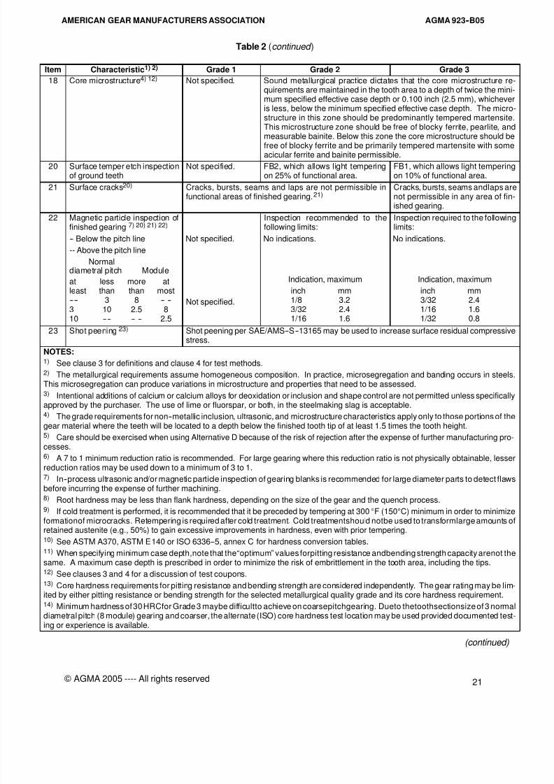
8/15/2019 AGMA 923-B05
http://slidepdf.com/reader/full/agma-923-b05 27/39
AGMA 923--B05AMERICAN GEAR MANUFACTURERS ASSOCIATION
21
© AGMA 2005 ---- All rights reserved
Table 2 (continued )
Item Characteristic1) 2) Grade 1 Grade 2 Grade 3
18 Core microstructure4) 12) Not specified. Sound metallurgical practice dictates that the core microstructure re-quirements are maintained in the tooth area to a depth of twice the mini-mum specified effective case depth or 0.100 inch (2.5 mm), whicheveris less, below the minimum specified effective case depth. The micro-structure in this zone should be predominantly tempered martensite.This microstructure zone should be free of blocky ferrite, pearlite, and
measurable bainite. Below this zone the core microstructure should befree of blocky ferrite and be primarily tempered martensite with someacicular ferrite and bainite permissible.
20 Surface temper etch inspectionof ground teeth
Not specified. FB2, which allows light temperingon 25% of functional area.
FB1, which allows light temperingon 10% of functional area.
21 Surface cracks20) Cracks, bursts, seams and laps are not permissible infunctional areas of finished gearing.21)
Cracks, bursts, seams andlaps arenot permissible in any area of fin-ished gearing.
22 Magnetic particle inspection offinished gearing 7) 20) 21) 22)
Inspection recommended to thefollowing limits:
Inspection required to the followinglimits:
-- Below the pitch line Not specified. No indications. No indications.
-- Above the pitch line
Normal
diametral pitch Moduleat less more atleast than than most---- 3 8 -- --3 10 2.5 810 ---- -- -- 2.5
Not specified.
Indication, maximum
inch mm1/8 3.23/32 2.41/16 1.6
Indication, maximum
inch mm3/32 2.41/16 1.61/32 0.8
23 Shot peening 23) Shot peening per SAE/AMS--S--13165 may be used to increase surface residual compressivestress.
NOTES:1) See clause 3 for definitions and clause 4 for test methods.2) The metallurgical requirements assume homogeneous composition. In practice, microsegregation and banding occurs in steels.This microsegregation can produce variations in microstructure and properties that need to be assessed.3) Intentional additions of calcium or calcium alloys for deoxidation or inclusion and shape control are not permitted unless specificallyapproved by the purchaser. The use of lime or fluorspar, or both, in the steelmaking slag is acceptable.4) The grade requirements for non--metallic inclusion, ultrasonic, and microstructure characteristics apply only to those portions of thegear material where the teeth will be located to a depth below the finished tooth tip of at least 1.5 times the tooth height.5) Care should be exercised when using Alternative D because of the risk of rejection after the expense of further manufacturing pro-cesses.6) A 7 to 1 minimum reduction ratio is recommended. For large gearing where this reduction ratio is not physically obtainable, lesserreduction ratios may be used down to a minimum of 3 to 1.7) In--process ultrasonic and/or magnetic particle inspection of gearing blanks is recommended for large diameter parts to detect flawsbefore incurring the expense of further machining.8) Root hardness may be less than flank hardness, depending on the size of the gear and the quench process.9) If cold treatment is performed, it is recommended that it be preceded by tempering at 300°F (150°C) minimum in order to minimizeformationof microcracks. Retempering is required after cold treatment. Cold treatmentshould notbe used to transformlarge amounts ofretained austenite (e.g., 50%) to gain excessive improvements in hardness, even with prior tempering.10) See ASTM A370, ASTM E140 or ISO 6336--5, annex C for hardness conversion tables.
11) When specifying minimum case depth,note that the“optimum” values forpitting resistance andbending strength capacity arenot thesame. A maximum case depth is prescribed in order to minimize the risk of embrittlement in the tooth area, including the tips.12) See clauses 3 and 4 for a discussion of test coupons.13) Core hardness requirements for pitting resistance and bending strength are considered independently. The gear rating may be lim-ited by either pitting resistance or bending strength for the selected metallurgical quality grade and its core hardness requirement.14) Minimum hardness of 30 HRCfor Grade 3 maybe difficultto achieve on coarsepitchgearing. Dueto thetoothsectionsize of 3 normaldiametral pitch (8 module) gearing and coarser, the alternate (ISO) core hardness test location may be used provided documented test-ing or experience is available.
(continued)
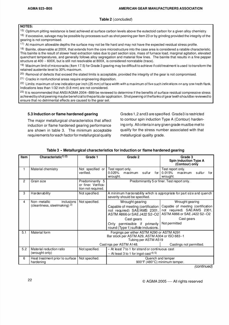
8/15/2019 AGMA 923-B05
http://slidepdf.com/reader/full/agma-923-b05 28/39
AGMA 923--B05 AMERICAN GEAR MANUFACTURERS ASSOCIATION
22 © AGMA 2005 ---- All rights reserved
Table 2 (concluded )
NOTES:15) Optimum pitting resistance is best achieved at surface carbon levels above the eutectoid carbon for a given alloy chemistry.16) If excessive, salvage may be possible by processes such as shot peening per Item 23 or by grinding provided the integrity of thegearing is not compromised.17) At maximum allowable depths the surface may not be file hard and may not have the expected residual stress profile.18) Bainite, observable at 200X, that extends from the core microstructure into the case area is considered a ratable characteristic.This bainite is the result of slower heat extraction rates due to part section size, mass of furnace load, marginal agitation, elevated
quenchant temperatures, and generally follows alloy segregation and material flow lines. The bainite that results in a fine pepperstructure at 400 -- 600X, but is still not resolvable at 800X, is considered nonratable (trace).19) Maximum limit of microcracks (Item 17.5) for Grade 3 gearing may be difficult to achieve if cold treatment is used to transform theretained austenite level to 30% maximum.20) Removal of defects that exceed the stated limits is acceptable, provided the integrity of the gear is not compromised.21) Cracks in nonfunctional areas require engineering disposition.22) Limits: maximum of one indication per inch (25 mm) of face width with a maximum of five such indications on any one tooth flank.Indications less than 1/32 inch (0.8 mm) are not considered.23) It is recommended that ANSI/AGMA 2004--B89 be reviewed to determine if the benefits of surface residual compressive stressachieved by shot peening maybe beneficial to theparticular application. Shot peening of theflanks of gear teeth shouldbe reviewed toensure that no detrimental effects are caused to the gear set.
5.3 Induction or flame hardened gearing
The major metallurgical characteristics that affect
induction or flame hardened gearing performance
are shown in table 3. The minimum acceptable
requirements for each factor for metallurgical quality
Grades 1,2 and3 are specified. Grade3 is restrictedto contour spin induction Type A (Contour) harden-
ing only. All criteria in any given grade mustbe met to
qualify for the stress number associated with that
metallurgical quality grade.
Table 3 -- Metallurgical characteristics for induction or flame hardened gearing
Item Characteristic1) 2) Grade 1 Grade 2 Grade 3Spin induction Type A
(Contour) only
1 Material chemistry Not specified orverified. Test report only.0.025% maximum sulfur forwrought.
Test report only.0.015% maximum sulfur forwrought.
2 Grain size Predominantly 5or finer. Verifica-tion not required.
Predominantly 5 or finer. Test report only.
3 Hardenability Not specif ied. A minimum hardenability which is appropriate for part size and quenchseverity should be specified.
4 Non--metallic inclusions(cleanliness, steelmaking) 3)
Not specified. Wrought gearing
Capable of meeting (certificationnot required) SAE/AMS 2301,ASTM A866 or SAE J422 S2--O2
Cast gears
Only permissible if primarily
round (Type 1) sulfide inclusions.
Wrought gearing
Capable of meeting (certificationnot required) SAE/AMS 2301,ASTM A866 or SAE J422 S2--O2
Cast gears
Not permitted
5.1 Material form Forgings per either ASTM A290 or ASTM A291Bar stock per ASTM A29, ASTM A304 or ISO 683--1
Tubing per ASTM A519
Castings per ASTM A148. Castings not permitted.
5.2 Material reduction ratio(wrought only)
Not specified. -- At least 7 to 1 for strand or continuous cast
-- At least 3 to 1 for ingot cast 4) 5)
6 Heat treatment prior to surfacehardening
Not specified. Quench and temper900°F (480°C) minimum temper.
(continued)
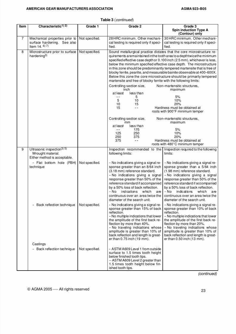
8/15/2019 AGMA 923-B05
http://slidepdf.com/reader/full/agma-923-b05 29/39
AGMA 923--B05AMERICAN GEAR MANUFACTURERS ASSOCIATION
23
© AGMA 2005 ---- All rights reserved
Table 3 (continued )
Item Characteristic1) 2) Grade 1 Grade 2 Grade 3Spin induction Type A
(Contour) only
7 Mechanical properties prior tosurface hardening. See alsoItem 14. 6) 7)
Not specified. 28 HRC minimum. Other mechani-cal testing is required only if speci-fied.
30 HRC minimum. Other mechani-cal testing is required only if speci-fied.
8 Microstructure prior to surfacehardening3)
Not specified. Sound metallurgical practice dictates that the core microstructure re-quirements aremaintained inthe tooth area to a depthtwicethe minimum
specified effective case depth or 0.100 inch (2.5 mm), whichever is less,below the minimum specified effective case depth. The microstructurein this zone should be predominantly tempered martensite that is free ofblocky ferrite, pearlite, and measurable bainite observable at 400--600X.
Below this zone the core microstructure should be primarily temperedmartensite and free of blocky ferrite with the following limits:
Controlling section size, Non--martensitic structures,inch maximum
at least less than---- 5 5%5 10 10%
10 15 20%15 -- -- Hardness must be obtained at
roots with 900°F minimum temper
Controlling section size, Non--martensitic structures,mm maximum
at least less than---- 125 5%
125 250 10%250 375 20%375 -- -- Hardness must be obtained at
roots with 480°C minimum temper
9 Ultrasonic inspection3) 5)
Wrought material.Either method is acceptable.
Inspection recommended to thefollowing limits:
Inspection required to the followinglimits:
-- Flat bottom hole (FBH)technique
Not specified. -- No indications giving a signal re-sponse greater than an 8/64 inch
(3.18 mm) reference standard.
-- No indications giving a signalresponse greater than 50% of thereference standard if accompanied
by a 50% loss of back reflection.-- No indications which arecontinuous over an area twice the
diameter of the search unit.
-- No indications giving a signal re-sponse greater than a 5/64 inch
(1.98 mm) reference standard.
-- No indications giving a signalresponse greater than 50% of thereference standard if accompanied
by a 50% loss of back reflection.-- No indications which arecontinuous over an area twice the
diameter of the search unit.
-- Back reflection technique Not specified. -- No indications giving a signal re-sponse greater than 15% of backreflection.-- No multiple indications that lowerthe amplitude of the first back re-flection by more than 40%.-- No traveling indications whoseamplitude is greater than 10% of
back reflection and length is great-er than 0.75 inch (19 mm).
-- No indications giving a signal re-sponse greater than 10% of backreflection.-- No multiple indications that lowerthe amplitude of the first back re-flection by more than 20%.-- No traveling indications whoseamplitude is greater than 10% of
back reflection and length is great-er than 0.50 inch (13 mm).
Castings
-- Back reflection technique Not specified. -- ASTM A609 Level 1 from outsidesurface to 1.5 times tooth heightbelow finished tooth tips.-- ASTM A609 Level 2 greater than1.5 times tooth height below fin-ished tooth tips.
(continued)
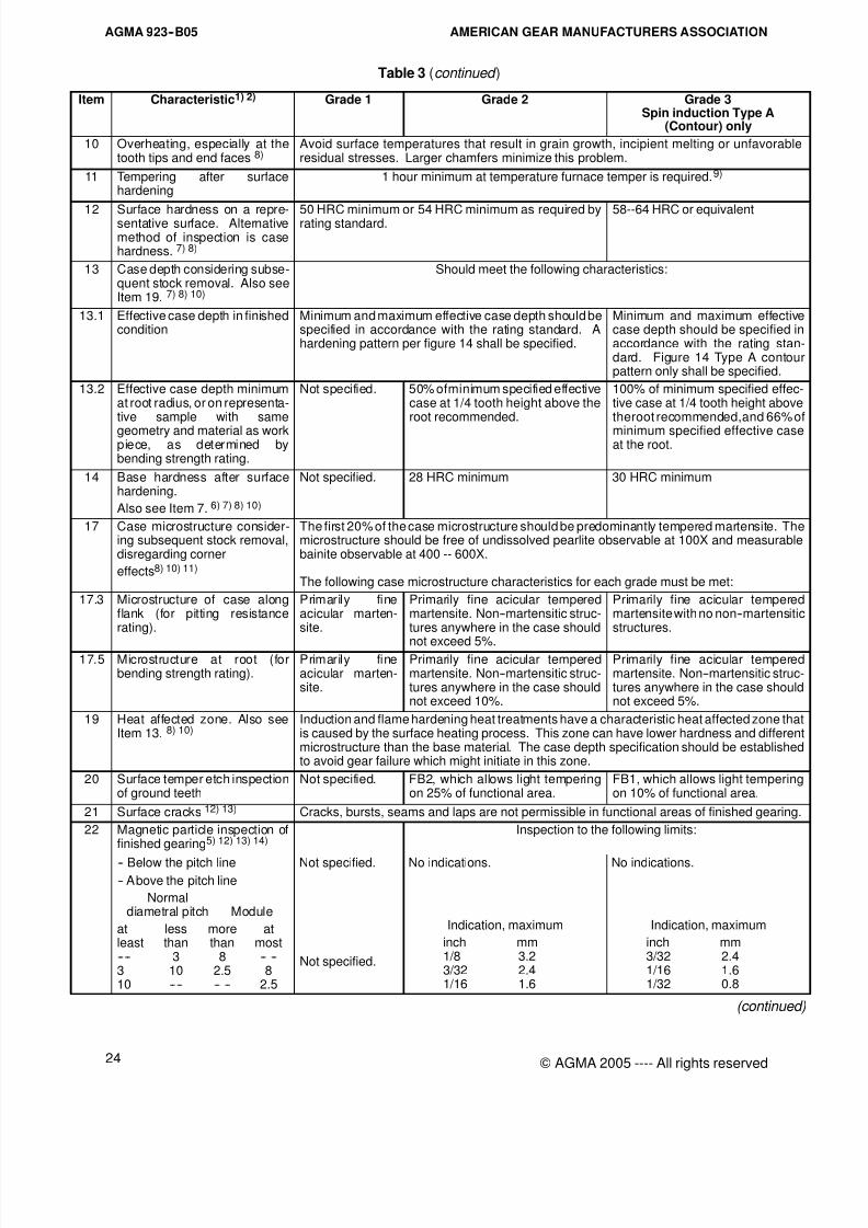
8/15/2019 AGMA 923-B05
http://slidepdf.com/reader/full/agma-923-b05 30/39
AGMA 923--B05 AMERICAN GEAR MANUFACTURERS ASSOCIATION
24 © AGMA 2005 ---- All rights reserved
Table 3 (continued )
Item Characteristic1) 2) Grade 1 Grade 2 Grade 3Spin induction Type A
(Contour) only
10 Overheating, especially at thetooth tips and end faces 8)
Avoid surface temperatures that result in grain growth, incipient melting or unfavorableresidual stresses. Larger chamfers minimize this problem.
11 Tempering after surfacehardening
1 hour minimum at temperature furnace temper is required.9)
12 Surface hardness on a repre-sentative surface. Alternativemethod of inspection is casehardness. 7) 8)
50 HRC minimum or 54 HRC minimum as required byrating standard. 58--64 HRC or equivalent
13 Case depth considering subse-quent stock removal. Also seeItem 19. 7) 8) 10)
Should meet the following characteristics:
13.1 Effective case depth in finishedcondition
Minimum and maximum effective case depth should bespecified in accordance with the rating standard. Ahardening pattern per figure 14 shall be specified.
Minimum and maximum effectivecase depth should be specified inaccordance with the rating stan-dard. Figure 14 Type A contourpattern only shall be specified.
13.2 Effective case depth minimumat root radius, or on representa-tive sample with same
geometry and material as workpiece, as determined bybending strength rating.
Not specified. 50% ofminimum specified effectivecase at 1/4 tooth height above theroot recommended.
100% of minimum specified effec-tive case at 1/4 tooth height abovetheroot recommended,and 66% of
minimum specified effective caseat the root.
14 Base hardness after surfacehardening.
Also see Item 7. 6) 7) 8) 10)
Not specified. 28 HRC minimum 30 HRC minimum
17 Case microstructure consider-ing subsequent stock removal,disregarding corner
effects8) 10) 11)
The first 20% of the case microstructure should be predominantly tempered martensite. Themicrostructure should be free of undissolved pearlite observable at 100X and measurablebainite observable at 400 -- 600X.
The following case microstructure characteristics for each grade must be met:
17.3 Microstructure of case alongflank (for pitting resistancerating).
Primarily fineacicular marten-site.
Primarily fine acicular temperedmartensite. Non--martensitic struc-tures anywhere in the case should
not exceed 5%.
Primarily fine acicular temperedmartensite with no non--martensiticstructures.
17.5 Microstructure at root (forbending strength rating).
Primarily fineacicular marten-site.
Primarily fine acicular temperedmartensite. Non--martensitic struc-tures anywhere in the case shouldnot exceed 10%.
Primarily fine acicular temperedmartensite. Non--martensitic struc-tures anywhere in the case shouldnot exceed 5%.
19 Heat affected zone. Also seeItem 13. 8) 10)
Induction and flame hardening heat treatments have a characteristic heat affected zone thatis caused by the surface heating process. This zone can have lower hardness and differentmicrostructure than the base material. The case depth specification should be establishedto avoid gear failure which might initiate in this zone.
20 Surface temper etch inspectionof ground teeth
Not specified. FB2, which allows light temperingon 25% of functional area.
FB1, which allows light temperingon 10% of functional area.
21 Surface cracks 12) 13) Cracks, bursts, seams and laps are not permissible in functional areas of finished gearing.
22 Magnetic particle inspection offinished gearing5) 12) 13) 14)
Inspection to the following limits:
-- Below the pitch line Not specified. No indications. No indications.-- Above the pitch line
Normaldiametral pitch Module
at less more atleast than than most---- 3 8 -- --3 10 2.5 810 ---- -- -- 2.5
Not specified.
Indication, maximum
inch mm1/8 3.23/32 2.41/16 1.6
Indication, maximum
inch mm3/32 2.41/16 1.61/32 0.8
(continued)
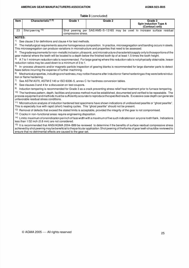
8/15/2019 AGMA 923-B05
http://slidepdf.com/reader/full/agma-923-b05 31/39
AGMA 923--B05AMERICAN GEAR MANUFACTURERS ASSOCIATION
25
© AGMA 2005 ---- All rights reserved
Table 3 (concluded )
Item Characteristic1) 2) Grade 1 Grade 2 Grade 3Spin induction Type A
(Contour) only
23 Shot peening 15) Shot peening per SAE/AMS--S--13165 may be used to increase surface residualcompressive stress.
NOTES:1) See clause 3 for definitions and clause 4 for test methods.2) The metallurgical requirements assume homogeneous composition. In practice, microsegregation and banding occurs in steels.This microsegregation can produce variations in microstructure and properties that need to be assessed.3) The graderequirements for non--metallic inclusion,ultrasonic, and microstructure characteristicsapply only to thoseportions of thegear material where the teeth will be located to a depth below the finished tooth tip of at least 1.5 times the tooth height.4) A 7 to 1 minimum reduction ratio is recommended. For large gearing where this reduction ratio is not physically obtainable, lesserreduction ratios may be used down to a minimum of 3 to 1.5) In--process ultrasonic and/or magnetic particle inspection of gearing blanks is recommended for large diameter parts to detectflaws before incurring the expense of further machining.6) Mechanical properties, includingcore hardness,may notbe thesame after inductionor flame hardeningas they were beforeinduc-tion or flame hardening.7) See ASTM A370, ASTM E140 or ISO 6336--5, annex C for hardness conversion tables.8) See clauses 3 and 4 for a discussion on test coupons.9) Induction tempering is recommended for Grade 3 as a crack preventing stress relief heat treatment prior to furnace tempering.10)
The hardness pattern, depth, facilities and process method must be established, documented and verified to be repeatable. Theprocess equipment and methods must be sufficiently accurate to reproduce the specified results. Excessive case depth can generateunfavorable residual stress conditions.11) Microstructure analysis of induction hardened test specimens have shown indications of undissolved pearlite or “ghost pearlite”.This is especially true with rapid (short) heating cycles. This “ghost pearlite” should not be present.12) Removal of defects that exceed the stated limits is acceptable, provided the integrity of the gear is not compromised.13) Cracks in non--functional areas require engineering disposition.14) Limits: maximum of oneindication perinch of face width with a maximum of five such indicationson anyone tooth flank. Indicationsless than 1/32 inch (0.8 mm) are not considered.15) It is recommended that ANSI/AGMA 2004--B89 be reviewed to determine if the benefits of surface residual compressive stressachieved by shot peening may be beneficial to theparticular application.Shot peening of theflanks of gear teeth shouldbe reviewed toensure that no detrimental effects are caused to the gear set.
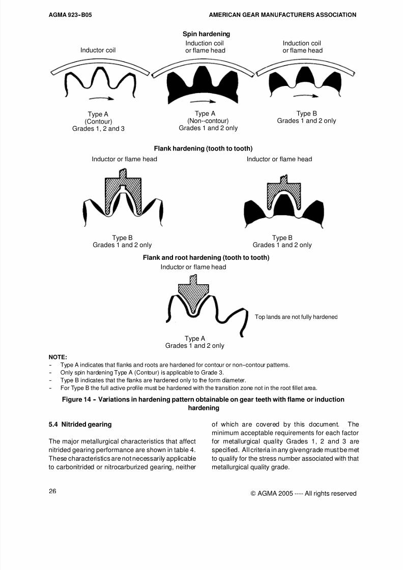
8/15/2019 AGMA 923-B05
http://slidepdf.com/reader/full/agma-923-b05 32/39
AGMA 923--B05 AMERICAN GEAR MANUFACTURERS ASSOCIATION
26 © AGMA 2005 ---- All rights reserved
Spin hardening
Flank hardening (tooth to tooth)
Flank and root hardening (tooth to tooth)
Type AGrades 1 and 2 only
Type A Type BGrades 1 and 2 only
Induction coilor flame head
Inductor or flame head Inductor or flame head
Inductor or flame head
(Non--contour)Grades 1 and 2 only
Inductor coil
Type A(Contour)
Grades 1, 2 and 3
Top lands are not fully hardened
Induction coilor flame head
Type BGrades 1 and 2 only
Type BGrades 1 and 2 only
NOTE:
-- Type A indicates that flanks and roots are hardened for contour or non--contour patterns.
-- Only spin hardening Type A (Contour) is applicable to Grade 3.
-- Type B indicates that the flanks are hardened only to the form diameter.
-- For Type B the full active profile must be hardened with the transition zone not in the root fillet area.
Figure 14 -- Variations in hardening pattern obtainable on gear teeth with flame or inductionhardening
5.4 Nitrided gearing
The major metallurgical characteristics that affect
nitrided gearing performance are shown in table 4.
These characteristics are not necessarily applicable
to carbonitrided or nitrocarburized gearing, neither
of which are covered by this document. The
minimum acceptable requirements for each factor
for metallurgical quality Grades 1, 2 and 3 are
specified. All criteria in any givengrade must be met
to qualify for the stress number associated with that
metallurgical quality grade.
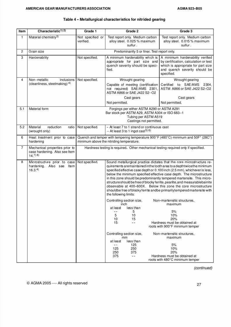
8/15/2019 AGMA 923-B05
http://slidepdf.com/reader/full/agma-923-b05 33/39
AGMA 923--B05AMERICAN GEAR MANUFACTURERS ASSOCIATION
27
© AGMA 2005 ---- All rights reserved
Table 4 -- Metallurgical characteristics for nitrided gearing
Item Characteristic1) 2) Grade 1 Grade 2 Grade 3
1 Material chemistry3) Not specified orverified.
Test report only. Medium carbonalloy steel. 0.025 % maximum
sulfur .
Test report only. Medium carbonalloy steel. 0.015 % maximum
sulfur .
2 Grain size Predominantly 5 or finer. Test report only.
3 Hardenability Not specified. A minimum hardenability which isappropriate for part size andquench severity should be speci-
fied.
A minimum hardenability verifiedby certification, calculation or testwhich is appropriate for part size
and quench severity should bespecified.
4 Non--metallic inclusions(cleanliness, steelmaking) 4)
Not specified. Wrought gearing
Capable of meeting (certificationnot required) SAE/AMS 2301,ASTM A866 or SAE J422 S2--O2
Cast gears
Not permitted.
Wrought gearing
Certified to SAE/AMS 2304,ASTM A866 or SAE J422 S2--O2
Cast gears
Not permitted.
5.1 Material form Forgings per either ASTM A290 or ASTM A291
Bar stock per ASTM A29, ASTM A304 or ISO 683--1Tubing per ASTM A519Castings not permitted.
5.2 Material reduction ratio(wrought only)
Not specified. -- At least 7 to 1 strand or continuous cast-- At least 3 to 1 ingot cast5) 6)
6 Heat treatment prior to casehardening
Quench and temper with tempering temperature 900°F (480°C) minimum and 50F° (28C°)minimum above the nitriding temperature.
7 Mechanical properties prior tocase hardening. Also see Item14.7) 8)
Hardness testing is required. Other mechanical testing required only if specified.
8 Microstructure prior to casehardening. Also see Item
16.3.
4)
Not specified. Sound metallurgical practice dictates that the core microstructure re-quirements aremaintained inthe tooth area to a depthtwicethe minimum
specified effective case depth or 0.100 inch (2.5 mm), whichever is less,below the minimum specified effective case depth. The microstructurein this zone should be predominantly tempered martensite. This micro-structure should be free of blocky ferrite, pearlite,and measurablebainiteobservable at 400--600X. Below this zone the core microstructure
shouldbe free of blocky ferrite andbe primarilytempered martensite withthe following limits:
Controlling section size, Non--martensitic structures,inch maximum
at least less than---- 5 5%5 10 10%
10 15 20%15 -- -- Hardness must be obtained at
roots with 900°F minimum temper
Controlling section size, Non--martensitic structures,mm maximum
at least less than---- 125 5%
125 250 10%250 375 20%375 -- -- Hardness must be obtained at
roots with 480°C minimum temper
(continued)

8/15/2019 AGMA 923-B05
http://slidepdf.com/reader/full/agma-923-b05 34/39
AGMA 923--B05 AMERICAN GEAR MANUFACTURERS ASSOCIATION
28 © AGMA 2005 ---- All rights reserved
Table 4 (continued )
Item Characteristic1) 2) Grade 1 Grade 2 Grade 3
9 Ultrasonic inspection4) 6)
Wrought material.Either method is acceptable.
Inspection recommended to thefollowing limits:
Inspection required to the followinglimits:
-- Flat bottom hole (FBH)technique
Not specified. -- No indications giving a signal re-sponse greater than an 8/64 inch(3.18 mm) reference standard.
-- No indications giving a signal re-sponse greater than a 5/64 inch(1.98 mm) reference standard.
-- No indications giving a signalresponse greater than 50% of thereference standard if accompaniedby a 50% loss of back reflection.
-- No indications giving a signalresponse greater than 50% of thereference standard if accompaniedby a 50% loss of back reflection.
-- No indications which arecontinuous over an area twice thediameter of the search unit.
-- No indications which arecontinuous over an area twice thediameter of the search unit.
-- Back reflection technique Not specified. -- No indications giving a signal re-sponse greater than 15% of backreflection.-- No multiple indications that lowerthe amplitude of the first back re-flection by more than 40%.-- No traveling indications whoseamplitude is greater than 10% of
back reflection and length is great-er than 0.75 inch (19 mm).
-- No indications giving a signal re-sponse greater than 10% of backreflection.-- No multiple indications that lowerthe amplitude of the first back re-flection by more than 20%.-- No traveling indications whoseamplitude is greater than 10% of
back reflection and length is great-er than 0.50 inch (13 mm).
12 Surface hardness on a repre-sentative surface. Alternativemethod of inspection is casehardness. 7)
-- Specialty nitriding steels9) Either 89 -- 93 HR15N, 650 -- 900 HV or 690 -- 900 HK
-- Through hardening steels Either 83 min HR15N, 450 min HV or 470 min HK
13 Case depth considering subse-quent stock removal10)
Should meet either of the following characteristics:
13.1 Effective case depth in finishedcondition
Minimum effective case depth requirements for the tooth should be specified in accordancewith the appropriate rating standard.
13.3 Total case depth in finished
condition
Minimum total case depth requirements for the tooth should be specified in accordance with
the appropriate rating standard.14 Core hardness after case hard-
ening. Also see item 7.7)28 HRC minimum 32 HRC minimum
16 Surface microstructureconsidering subsequent stockremoval 10)
The first 0.002 -- 0.003 inch (0.05 -- 0.08 mm) of case microstructure in the tooth area shouldmeet thesurface hardness requirement of the specific grade and also meet thefollowing sur-face related characteristics and the requirements of Item 17:
16.3 Decarburization. No decarburization permitted on surface to be nitrided.
-- Method 1. Not applicable.
-- Method 2. Reduction of hard-ness by two load method. 7)
Not specified. Maximum 2 HRC points or equiva-lent below maximum measuredhardness by conversion.
No reduction in hardness belowmaximum measured hardness byconversion is permissible.
-- Method 3. Metallographicevaluation.
Not specified. No partial decarburization appar-ent except in unground roots.
No partial decarburizationapparent.
16.4 Epsilon (Á) nitride (white layer)along flank or in root
Minimum specifiedeffective case depth
inch (mm)at less at less
least than least than-- -- 0.015 -- -- (0.37)0.015 ---- (0.37) ----
Maximumallowable depthinch (mm)0.0010 (0.025)0.0010 (0.025)
Maximum allowable depthinch (mm)
0.0008 (0.019)0.0008 (0.019)
Maximum allowable depthinch (mm)
0.0005 (0.012)0.0008 (0.019)
(continued)
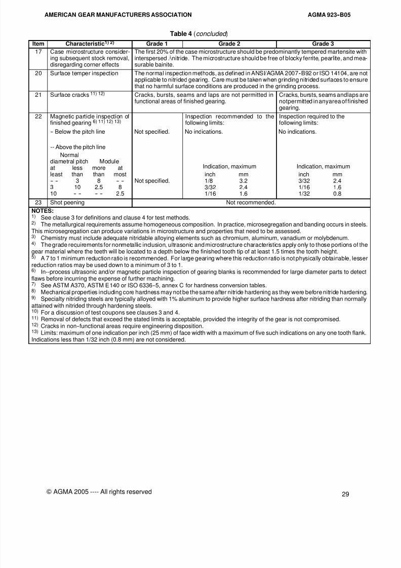
8/15/2019 AGMA 923-B05
http://slidepdf.com/reader/full/agma-923-b05 35/39
AGMA 923--B05AMERICAN GEAR MANUFACTURERS ASSOCIATION
29
© AGMA 2005 ---- All rights reserved
Table 4 (concluded )
Item Characteristic1) 2) Grade 1 Grade 2 Grade 3
17 Case microstructure consider-ing subsequent stock removal,disregarding corner effects
The first 20% of the case microstructure should be predominantly tempered martensite withinterspersedÁnitride. The microstructure should be free of blocky ferrite, pearlite, and mea-surable bainite.
20 Surface temper inspection The normal inspection methods, as defined in ANSI/AGMA 2007--B92 or ISO 14104, are notapplicable to nitrided gearing. Care must be taken when grinding nitrided surfaces to ensurethat no harmful surface conditions are produced in the grinding process.
21 Surface cracks 11) 12) Cracks, bursts, seams and laps are not permitted in
functional areas of finished gearing.
Cracks, bursts, seams andlaps are
notpermitted in anyarea of finishedgearing.
22 Magnetic particle inspection offinished gearing 6) 11) 12) 13)
Inspection recommended to thefollowing limits:
Inspection required to thefollowing limits:
-- Below the pitch line Not specified. No indications. No indications.
-- Above the pitch line
Normaldiametral pitch Moduleat less more atleast than than most-- -- 3 8 -- --3 10 2.5 810 -- -- -- -- 2.5
Not specified.
Indication, maximum
inch mm1/8 3.23/32 2.41/16 1.6
Indication, maximum
inch mm3/32 2.41/16 1.61/32 0.8
23 Shot peening Not recommended.
NOTES:1) See clause 3 for definitions and clause 4 for test methods.2) The metallurgical requirements assume homogeneous composition. In practice, microsegregation and banding occurs in steels.This microsegregation can produce variations in microstructure and properties that need to be assessed.3) Chemistry must include adequate nitridable alloying elements such as chromium, aluminum, vanadium or molybdenum.4) The grade requirements for nonmetallic inclusion, ultrasonic and microstructure characteristics apply only to those portions of thegear material where the teeth will be located to a depth below the finished tooth tip of at least 1.5 times the tooth height.5) A 7 to 1 minimum reduction ratio is recommended. For large gearing where this reduction ratio is not physically obtainable, lesserreduction ratios may be used down to a minimum of 3 to 1.6) In--process ultrasonic and/or magnetic particle inspection of gearing blanks is recommended for large diameter parts to detectflaws before incurring the expense of further machining.7) See ASTM A370, ASTM E140 or ISO 6336--5, annex C for hardness conversion tables.8) Mechanical properties including core hardness may not be the same after nitride hardening as they were before nitride hardening.
9) Specialty nitriding steels are typically alloyed with 1% aluminum to provide higher surface hardness after nitriding than normallyattained with nitrided through hardening steels.10) For a discussion of test coupons see clauses 3 and 4.11) Removal of defects that exceed the stated limits is acceptable, provided the integrity of the gear is not compromised.12) Cracks in non--functional areas require engineering disposition.13) Limits: maximum of one indication per inch (25 mm) of face width with a maximum of five such indications on any one tooth flank.Indications less than 1/32 inch (0.8 mm) are not considered.

8/15/2019 AGMA 923-B05
http://slidepdf.com/reader/full/agma-923-b05 36/39
AGMA 923--B05 AMERICAN GEAR MANUFACTURERS ASSOCIATION
30 © AGMA 2005 ---- All rights reserved
(This page is intentionally left blank.)
8/15/2019 AGMA 923-B05
http://slidepdf.com/reader/full/agma-923-b05 37/39
AGMA 923--B05AMERICAN GEAR MANUFACTURERS ASSOCIATION
31
© AGMA 2005 ---- All rights reserved
Bibliography
The following documents are either referenced in the text of AGMA 923--B05, Metallurgical Specifications for
Steel Gearing, or indicated for additional information.
ANSI/AGMA 6033--B98, Materials for Marine Pro-
pulsion Gearing
ASM Handbook, Volume 1 -- Properties and selec-
tion: Irons, steels and high--performance alloys ,
ASM International, Materials Park, Ohio, 1990
ASM Handbook, Volume 4 -- Heat treating , ASM
International, Materials Park, Ohio, 1991
Boyer, Howard E., Ed., Hardness Testing, ASM
International, Materials Park, Ohio, 1987
Doane, D.V. and Semchyshen, M., Modern carbu-
rized nickel alloy steel , NickelDevelopment Institute,
Toronto, 1990
Heat Treater’s Guide -- Practices and procedures for
irons and steels , ASM International, Materials Park,
Ohio, 1995
Kern, Roy F. and Suess, Manfred E., Steel Selection
-- A guide for improving performance and profits ,
John Wiley & Sons, New York, 1979
Krauss, G., Steels: Heat Treatment and Processing
Principles, ASM International, Materials Park, Ohio,
1996
Parish, Geoffrey, Carburizing: Microstructures and
Properties, ASM International, Materials Park, Ohio,
1999Practical Data for Metallurgists , 14th edition, The
Timken Company, Canton, Ohio, 1999
Reed--Hill, R.E., Physical Metallurgy Principles , D.
Van Nostrand, New York, 1973
Totten, G.E., and Howes, M.A.H., Steel Heat Treat-
ment Handbook , Marcel Dekker, New York, 1997

8/15/2019 AGMA 923-B05
http://slidepdf.com/reader/full/agma-923-b05 38/39
8/15/2019 AGMA 923-B05
http://slidepdf.com/reader/full/agma-923-b05 39/39
PUBLISHED BYAMERICAN GEAR MANUFACTURERS ASSOCIATION