Embed Size (px)
Citation preview
Agreement
Concerning the Adoption of Harmonized Technical United Nations
Regulations for Wheeled Vehicles, Equipment and Parts which can be
Fitted and/or be Used on Wheeled Vehicles and the Conditions for
Reciprocal Recognition of Approvals Granted on the Basis of these
United Nations Regulations*
(Revision 3, including the amendments which entered into force on 14 September 2017)
________________
Addendum 78: UN Regulation No. 79
Revision 3
Incorporating all valid text up to:
Revision 2 – incl. Erratum
Supplement 4 to the 01 series of amendments – Date of entry into force: 13 February 2014
Supplement 5 to the 01 series of amendments – Date of entry into force: 9 February 2017
02 series of amendments – Date of entry into force: 10 October 2017
Uniform provisions concerning the approval of vehicles with regard to steering equipment
This document is meant purely as documentation tool. The authentic and legal binding texts are:
ECE/TRANS/WP.29/2016/57
ECE/TRANS/WP.29/2017/10 (as amended by paragraph 70 of the report ECE/TRANS/WP.29/1129)
_______________
UNITED NATIONS
* Former titles of the Agreement:
Agreement concerning the Adoption of Uniform Conditions of Approval and Reciprocal Recognition of
Approval for Motor Vehicle Equipment and Parts, done at Geneva on 20 March 1958 (original version); Agreement concerning the Adoption of Uniform Technical Prescriptions for Wheeled Vehicles,
Equipment and Parts which can be Fitted and/or be Used on Wheeled Vehicles and the Conditions for
Reciprocal Recognition of Approvals Granted on the Basis of these Prescriptions, done at Geneva on
5 October 1995 (Revision 2).
E/ECE/324/Rev.1/Add.78/Rev.3 −E/ECE/TRANS/505/Rev.1/Add.78/Rev.3
30 November 2017

E/ECE/324/Rev.1/Add.78/Rev.3
E/ECE/TRANS/505/Rev.1/Add.78/Rev.3
3
UN Regulation No. 79
Uniform provisions concerning the approval of vehicles with regard to steering equipment
Contents
Page
Regulation
Introduction ...................................................................................................................................... 4
1. Scope ................................................................................................................................................ 5
2. Definitions ........................................................................................................................................ 5
3. Application for approval .................................................................................................................. 10
4. Approval ........................................................................................................................................... 11
5. Constructions provisions .................................................................................................................. 12
6. Test provisions ................................................................................................................................. 22
7. Conformity of production ................................................................................................................. 24
8. Penalties for non-conformity of production ..................................................................................... 24
9. Modifications and extension of approval of the vehicle type ........................................................... 24
10. Production definitively discontinued ................................................................................................ 25
11. Names and addresses of Technical Services responsible for conducting approval tests and of
Type Approval Authorities ............................................................................................................... 25
12. Transitional provisions ..................................................................................................................... 25
Annexes
1 Communication concerning the approval or refusal or extension or withdrawal of approval or
production definitively discontinued of a vehicle type with regard to steering equipment pursuant to
Regulation No. 79 ............................................................................................................................ 27
2 Arrangements of approval marks ..................................................................................................... 29
3 Braking performance for vehicles using the same energy source to supply steering equipment
and braking device ........................................................................................................................... 30
4 Additional provisions for vehicles equipped with Auxiliary Steering Equipment ........................... 32
5 Provision for trailers having hydraulic steering transmission .......................................................... 34
6 Special requirements to be applied to the safety aspects of complex electronic vehicle
control systems ................................................................................................................................. 35
7 Special provisions for the powering of trailer steering systems from the towing vehicle ................ 40
8 Test requirements for corrective and automatically commanded steering functions........................ 43
E/ECE/324/Rev.1/Add.78/Rev.3
E/ECE/TRANS/505/Rev.1/Add.78/Rev.3
4
Introduction
The intention of the Regulation is to establish uniform provisions for the
layout and performance of steering systems fitted to vehicles used on the
road. Traditionally the major requirement has been that the main steering
system contains a positive mechanical link between the steering control,
normally the steering wheel, and the road wheels in order to determine the
path of the vehicle. The mechanical link, if amply dimensioned, has been
regarded as not being liable to failure.
Advancing technology, coupled with the wish to improve occupant safety by
elimination of the mechanical steering column, and the production
advantages associated with easier transfer of the steering control between left
and right hand drive vehicles, has led to a review of the traditional approach
and the Regulation is now amended to take account of the new technologies.
Accordingly it will now be possible to have steering systems in which there
is not any positive mechanical connection between the steering control and
the road wheels.
Systems whereby the driver remains in primary control of the vehicle but
may be helped by the steering system being influenced by signals initiated
on-board the vehicle are defined as "Advanced Driver Assistance Steering
Systems". Such systems can incorporate an "Automatically Commanded
Steering Function", for example, using passive infrastructure features to
assist the driver in keeping the vehicle on an ideal path (Lane Guidance, Lane
Keeping or Heading Control), to assist the driver in manoeuvring the vehicle
at low speed in confined spaces or to assist the driver in coming to rest at a
pre-defined point (Bus Stop Guidance). Advanced Driver Assistance Steering
Systems can also incorporate a "Corrective Steering Function" that, for
example, warns the driver of any deviation from the chosen lane (Lane
Departure Warning), corrects the steering angle to prevent departure from the
chosen lane (Lane Departure Avoidance) or corrects the steering angle of one
or more wheels to improve the vehicle's dynamic behaviour or stability.
In the case of any Advanced Driver Assistance Steering System, the driver
can, at all times, choose to override the assistance function by deliberate
action, for example, to avoid an unforeseen object in the road.
It is anticipated that future technology will also allow steering to be
influenced or controlled by sensors and signals generated either on or off-
board the vehicle. This has led to several concerns regarding responsibility
for the primary control of the vehicle and the absence of any internationally
agreed data transmission protocols with respect to off-board or external
control of steering. Therefore, the Regulation does not permit the general
approval of systems that incorporate functions by which the steering can be
controlled by external signals, for example, transmitted from roadside
beacons or active features embedded into the road surface. Such systems,
which do not require the presence of a driver, have been defined as
"Autonomous Steering Systems".
This Regulation also prevents the approval of positive steering of trailers by
means of electrical control from the towing vehicle as there are currently no
standards applicable to this application. It is expected that at some time in the
future, ISO 11992 will be amended to include messages associated with the
transmission of steering control.
E/ECE/324/Rev.1/Add.78/Rev.3
E/ECE/TRANS/505/Rev.1/Add.78/Rev.3
5
1. Scope
1.1. This Regulation applies to the steering equipment of vehicles of categories
M, N and O.1
1.2. This Regulation does not apply to:
1.2.1. Steering equipment with a purely pneumatic transmission;
1.2.2. Autonomous Steering Systems as defined in paragraph 2.3.3.;
1.2.3. Steering systems exhibiting the functionality defined as ACSF of Category
B2, C, D or E in paragraphs 2.3.4.1.3., 2.3.4.1.4., 2.3.4.1.5., or 2.3.4.1.6.,
respectively, until specific provisions would be introduced in this Regulation.
2. Definitions
For the purposes of this Regulation:
2.1. "Approval of a vehicle" means the approval of a vehicle type with regard to
its steering equipment.
2.2. "Vehicle type" means a vehicle which does not differ with respect to the
manufacturer's designation of the vehicle type and in essential characteristics
such as:
2.2.1. Type of steering equipment, steering control, steering transmission, steered
wheels, and energy source.
2.3. "Steering equipment" means all the equipment the purpose of which is to
determine the direction of movement of the vehicle.
The steering equipment consists of:
- The steering control,
- The steering transmission,
- The steered wheels,
- The energy supply, if any.
2.3.1. "Steering control" means the part of the steering equipment which controls its
operation; it may be operated with or without direct intervention of the
driver. For steering equipment in which the steering forces are provided
solely or partly by the muscular effort of the driver the steering control
includes all parts up to the point where the steering effort is transformed by
mechanical, hydraulic or electrical means;
2.3.2. "Steering transmission" means all components which form a functional link
between the steering control and the road wheels.
The transmission is divided into two independent functions:
The control transmission and the energy transmission.
1 As defined in the Consolidated Resolution on the Construction of Vehicles (R.E.3), document
ECE/TRANS/WP.29/78/Rev.6, para. 2 -
www.unece.org/trans/main/wp29/wp29wgs/wp29gen/wp29resolutions.html
E/ECE/324/Rev.1/Add.78/Rev.3
E/ECE/TRANS/505/Rev.1/Add.78/Rev.3
6
Where the term "transmission" is used alone in this Regulation, it means both
the control transmission and the energy transmission. A distinction is drawn
between mechanical, electrical and hydraulic transmission systems or
combinations thereof, according to the means by which the signals and/or
energy is transmitted.
2.3.2.1. "Control transmission" means all components by means of which signals are
transmitted for control of the steering equipment.
2.3.2.2. "Energy transmission" means all components by means of which the energy
required for control/regulation of the steering function of the wheels is
transmitted.
2.3.3. "Autonomous Steering System" means a system that incorporates a function
within a complex electronic control system that causes the vehicle to follow a
defined path or to alter its path in response to signals initiated and transmitted
from off-board the vehicle. The driver will not necessarily be in primary
control of the vehicle.
2.3.4. "Advanced Driver Assistance Steering System" means a system, additional to
the main steering system, that provides assistance to the driver in steering the
vehicle but in which the driver remains at all times in primary control of the
vehicle. It comprises one or both of the following functions:
2.3.4.1. "Automatically commanded steering function (ACSF)" means a function
within an electronic control system where actuation of the steering system
can result from automatic evaluation of signals initiated on-board the vehicle,
possibly in conjunction with passive infrastructure features, to generate
control action in order to assist the driver.
2.3.4.1.1. "ACSF of Category A" means a function that operates at a speed no greater
than 10 km/h to assist the driver, on demand, in low speed or parking
manoeuvring.
2.3.4.1.2. "ACSF of Category B1" means a function which assists the driver in keeping
the vehicle within the chosen lane, by influencing the lateral movement of the
vehicle.
2.3.4.1.3. "ACSF of Category B2" means a function which is initiated/activated by the
driver and which keeps the vehicle within its lane by influencing the lateral
movement of the vehicle for extended periods without further driver
command/confirmation
2.3.4.1.4. "ACSF of Category C" means, a function which is initiated/activated by the
driver and which can perform a single lateral manoeuvre (e.g. lane change)
when commanded by the driver.
2.3.4.1.5. "ACSF of Category D" means a function which is initiated/activated by the
driver and which can indicate the possibility of a single lateral manoeuvre
(e.g. lane change) but performs that function only following a confirmation
by the driver.
2.3.4.1.6. "ACSF of Category E" means a function which is initiated/activated by the
driver and which can continuously determine the possibility of a manoeuvre
(e.g. lane change) and complete these manoeuvres for extended periods
without further driver command/confirmation.
E/ECE/324/Rev.1/Add.78/Rev.3
E/ECE/TRANS/505/Rev.1/Add.78/Rev.3
7
2.3.4.2. "Corrective Steering Function (CSF)" means a control function within an
electronic control system whereby, for a limited duration, changes to the
steering angle of one or more wheels may result from the automatic
evaluation of signals initiated on-board the vehicle, in order:
(a) To compensate a sudden, unexpected change in the side force of the
vehicle, or;
(b) To improve the vehicle stability (e.g. side wind, differing adhesion
road conditions "μ-split"), or;
(c) To correct lane departure. (e.g. to avoid crossing lane markings,
leaving the road).
2.3.5. "Steered wheels" means the wheels, the alignment of which may be altered
directly or indirectly in relation to the longitudinal axis of the vehicle in order
to determine the direction of movement of the vehicle. (The steered wheels
include the axis around which they are rotated in order to determine the
direction of movement of the vehicle);
2.3.6. "Energy supply" includes those parts of the steering equipment which provide
it with energy, regulate that energy and where appropriate, process and store
it. It also includes any storage reservoirs for the operating medium and the
return lines, but not the vehicle's engine (except for the purpose of
paragraph 5.3.2.1.) or its drive to the energy source.
2.3.6.1. "Energy source" means the part of the energy supply, which provides the
energy in the required form.
2.3.6.2. "Energy reservoir" means that part of the energy supply in which the energy
provided by the energy source is stored, for example, a pressurised fluid
reservoir or vehicle battery.
2.3.6.3. "Storage reservoir" means that part of the energy supply in which the
operating medium is stored at or near to the atmospheric pressure, for
example a fluid reservoir.
2.4. Steering parameters
2.4.1. "Steering control effort" means the force applied to the steering control in
order to steer the vehicle.
2.4.2. "Steering time" means the period of time from the beginning of the
movement of the steering control to the moment at which the steered wheels
have reached a specific steering angle.
2.4.3. "Steering angle" means the angle between the projection of a longitudinal
axis of the vehicle and the line of intersection of the wheel plane (being the
central plane of the wheel, normal to the axis around which it rotates) and the
road surface.
2.4.4. "Steering forces" mean all the forces operating in the steering transmission.
2.4.5. "Mean steering ratio" means the ratio of the angular displacement of the
steering control to the mean of the swept steering angle of the steered wheels
for a full lock-to-lock turn.
E/ECE/324/Rev.1/Add.78/Rev.3
E/ECE/TRANS/505/Rev.1/Add.78/Rev.3
8
2.4.6. "Turning circle" means the circle within which are located the projections
onto the ground plane of all the points of the vehicle, excluding the external
devices for indirect vision and the front direction indicators, when the vehicle
is driven in a circle.
2.4.7. "Nominal radius of steering control" means in the case of a steering wheel
the shortest dimension from its centre of rotation to the outer edge of the rim.
In the case of any other form of control it means the distance between its
centre of rotation and the point at which the steering effort is applied. If more
than one such point is provided, the one requiring the greatest effort shall be
used.
2.4.8. "Remote Controlled Parking (RCP)" means an ACSF of category A, actuated
by the driver, providing parking or low speed manoeuvring. The actuation is
made by remote control in close proximity to the vehicle.
2.4.9. "Specified maximum RCP operating range (SRCPmax)" means the maximum
distance between the nearest point of the motor vehicle and the remote
control device up to which ACSF is designed to operate.
2.4.10. "Specified maximum speed Vsmax " means the maximum speed up to which an
ACSF is designed to operate.
2.4.11. "Specified minimum speed Vsmin" means the minimum speed down to which
an ACSF is designed to operate.
2.4.12. "Specified maximum lateral acceleration aysmax" means the maximum lateral
acceleration of the vehicle up to which an ACSF is designed to operate.
2.4.13. An ACSF is in "off mode" (or "switched off") when the function is prevented
from generating a steering control action to assist the driver.
2.4.14. An ACSF is in "standby mode" when the function is switched on, but the
conditions (e.g. system operating conditions, deliberate action from driver)
for being active are not all met. In this mode, the system is not ready to
generate a steering control action to assist the driver.
2.4.15. An ACSF is in "active mode" (or "active") when the function is switched on
and the conditions for being active are met. In this mode, the system
continuously or discontinuously controls the steering system is generating, or
is ready to generate, a steering control action to assist the driver.
2.5. Types of steering equipment
Depending on the way the steering forces are produced, the following types
of equipment are distinguished:
2.5.1. For motor vehicles:
2.5.1.1. "Main steering system" means the steering equipment of a vehicle which is
mainly responsible for determining the direction of travel. It may comprise:
2.5.1.1.1. "Manual steering equipment" in which the steering forces result solely from
the muscular effort of the driver;
2.5.1.1.2. "Power assisted steering equipment" in which the steering forces result from
both the muscular effort of the driver and the energy supply (supplies).
E/ECE/324/Rev.1/Add.78/Rev.3
E/ECE/TRANS/505/Rev.1/Add.78/Rev.3
9
2.5.1.1.2.1. Steering equipment in which the steering forces result solely from one or
more energy supplies when the equipment is intact, but in which the steering
forces can be provided by the muscular effort of the driver alone if there is a
fault in the steering (integrated power systems), is also considered to be
power assisted steering equipment;
2.5.1.1.3. "Full-power steering equipment" in which the steering forces are provided
solely by one or more energy supplies;
2.5.1.2. "Self-tracking steering equipment" means a system designed to create a
change of steering angle on one or more wheels only when acted upon by
forces and/or moments applied through the tyre to road contact.
2.5.1.3. "Auxiliary Steering Equipment (ASE)" means a system in which the wheels
on axle(s) of vehicles of categories M and N are steered in addition to the
wheels of the main steering equipment in the same or opposite direction to
those of the main steering equipment and/or the steering angle of the front
and/or the rear wheels may be adjusted relative to vehicle behaviour.
2.5.2. For trailers:
2.5.2.1. "Self-tracking steering equipment" means a system designed to create a
change of steering angle on one or more wheels only when acted upon by
forces and/or moments applied through the tyre to road contact.
2.5.2.2. "Articulated steering" means equipment in which the steering forces are
produced by a change in direction of the towing vehicle and in which the
movement of the steered trailer wheels is linked to the relative angle between
the longitudinal axis of the towing vehicle and that of the trailer.
2.5.2.3. "Self-steering" means equipment in which the steering forces are produced by
a change in direction of the towing vehicle and in which the movement of the
steered trailer wheels is firmly linked to the relative angle between the
longitudinal axis of the trailer frame or a load replacing it and the
longitudinal axis of the sub-frame to which the axle(s) is (are) attached.
2.5.2.4. "Additional steering equipment" means a system, independent of the main
steering system, by which the steering angle of one or more axle(s) of the
steering system can be influenced selectively for manoeuvring purposes.
2.5.2.5. "Full-power steering equipment" means equipment in which the steering
forces are provided solely by one or more energy supplies.
2.5.3. Depending on the arrangement of the steered wheels, the following types of
steering equipment are distinguished:
2.5.3.1. "Front-wheel steering equipment" in which only the wheels of the front
axle(s) are steered. This includes all wheels which are steered in the same
direction;
2.5.3.2. "Rear-wheel steering equipment" in which only the wheels of the rear axle(s)
are steered. This includes all wheels which are steered in the same direction;
2.5.3.3. "Multi-wheel steering equipment" in which the wheels of one or more of each
of the front and the rear axle(s) are steered;
2.5.3.3.1. "All-wheel steering equipment" in which all the wheels are steered;
2.5.3.3.2. "Buckle steering equipment" in which the movement of chassis parts relative
to each other is directly produced by the steering forces.
E/ECE/324/Rev.1/Add.78/Rev.3
E/ECE/TRANS/505/Rev.1/Add.78/Rev.3
10
2.6. Types of steering transmission
Depending on the way the steering forces are transmitted, the following types
of steering transmission are distinguished:
2.6.1. "Purely mechanical steering transmission" means a steering transmission in
which the steering forces are transmitted entirely by mechanical means;
2.6.2. "Purely hydraulic steering transmission" means a steering transmission in
which the steering forces, somewhere in the transmission, are transmitted
only by hydraulic means;
2.6.3. "Purely electric steering transmission" means a steering transmission in
which the steering forces, somewhere in the transmission, are transmitted
only through electric means;
2.6.4. "Hybrid steering transmission" means a steering transmission in which part
of the steering forces is transmitted through one and the other part through
another of the above mentioned means. However, in the case where any
mechanical part of the transmission is designed only to give position
feedback and is too weak to transmit the total sum of the steering forces, this
system shall be considered to be purely hydraulic or purely electric steering
transmission.
2.7. "Electric control line" means the electrical connection which provides the
steering control function to the trailer. It comprises the electrical wiring and
connector and includes the parts for data communication and the electrical
energy supply for the trailer control transmission.
3. Application for approval
3.1. The application for approval of a vehicle type with regard to the steering
equipment shall be submitted by the vehicle manufacturer or by his duly
accredited representative.
3.2. It shall be accompanied by the undermentioned documents in triplicate, and
by the following particulars:
3.2.1. A description of the vehicle type with regard to the items mentioned in
paragraph 2.2.; the vehicle type shall be specified;
3.2.2. A brief description of the steering equipment with a diagram of the steering
equipment as a whole, showing the position on the vehicle of the various
devices influencing the steering;
3.2.3. In the case of full power steering systems and systems to which Annex 6 of
this Regulation applies, an overview of the system indicating the philosophy
of the system and the fail-safe procedures, redundancies and warning systems
necessary to ensure safe operation in the vehicle.
The necessary technical files relating to such systems shall be made available
for discussion with the Type Approval Authority and/or Technical Service.
Such files will be discussed on a confidential basis.
3.3. A vehicle representative of the vehicle type to be approved shall be submitted
to the Technical Service responsible for conducting approval tests.
E/ECE/324/Rev.1/Add.78/Rev.3
E/ECE/TRANS/505/Rev.1/Add.78/Rev.3
11
4. Approval
4.1. If the vehicle submitted for approval pursuant to this Regulation meets all
relevant requirements given in this Regulation, approval of that vehicle type
with regard to the steering equipment shall be granted.
4.1.1. The Type Approval Authority shall verify the existence of satisfactory
arrangements for ensuring effective control of the conformity of production
as given in paragraph 7. of this Regulation, before type approval is granted.
4.2. An approval number shall be assigned to each type approved. Its first two
digits (at present 02) shall indicate the series of amendments incorporating
the most recent major technical amendments made to the Regulation at the
time of issue of the approval. The same Contracting Party shall not assign
this number to another vehicle type or to the same vehicle type submitted
with different steering equipment from that described in the documents
required by paragraph 3.
4.3. Notice of approval or of extension or refusal of approval of a vehicle type
pursuant to this Regulation shall be communicated to the Parties to the 1958
Agreement which apply this Regulation, by means of a form conforming to
the model in Annex 1 to this Regulation.
4.4. There shall be affixed, conspicuously and in a readily accessible place
specified on the approval form, to every vehicle conforming to a vehicle type
approved under this Regulation, an international approval mark consisting of:
4.4.1. a circle surrounding the letter "E" followed by the distinguishing number of
the country which has granted approval;2
4.4.2. the number of this Regulation, followed by the letter "R", a dash and the
approval number to the right of the circle prescribed in paragraph 4.4.1.
4.5. If the vehicle conforms to a vehicle type approved, under one or more other
Regulations annexed to the Agreement, in the country which has granted
approval under this Regulation, the symbol prescribed in paragraph 4.4.1.
need not be repeated; in such a case the Regulation and approval numbers
and the additional symbols of all the Regulations under which approval has
been granted in the country which has granted approval under this Regulation
shall be placed in vertical columns to the right of the symbol prescribed in
paragraph 4.4.1.
4.6. The approval mark shall be clearly legible and shall be indelible.
4.7. The approval mark shall be placed close to or on the vehicle data plate
affixed by the manufacturer.
4.8. Annex 2 to this Regulation gives examples of arrangements of approval
marks.
2 The distinguishing numbers of the Contracting Parties to the 1958 Agreement are reproduced in
Annex 3 to the Consolidated Resolution on the Construction of Vehicles (R.E.3), document
ECE/TRANS/WP.29/78/Rev. 6, Annex 3 -
www.unece.org/trans/main/wp29/wp29wgs/wp29gen/wp29resolutions.html
E/ECE/324/Rev.1/Add.78/Rev.3
E/ECE/TRANS/505/Rev.1/Add.78/Rev.3
12
5. Construction provisions
5.1. General provisions
5.1.1. The steering system shall ensure easy and safe handling of the vehicle up to
its maximum design speed or in case of a trailer up to its technically
permitted maximum speed. There shall be a tendency to self-centre when
tested in accordance with paragraph 6.2. with the intact steering equipment.
The vehicle shall meet the requirements of paragraph 6.2. in the case of
motor vehicles and of paragraph 6.3. in the case of trailers. If a vehicle is
fitted with an auxiliary steering system, it shall also meet the requirements of
Annex 4. Trailers equipped with hydraulic steering transmissions shall
comply also with Annex 5.
5.1.2. It shall be possible to travel along a straight section of road without unusual
steering correction by the driver and without unusual vibration in the steering
system at the maximum design speed of the vehicle.
5.1.3. The direction of operation of the steering control shall correspond to the
intended change of direction of the vehicle and there shall be a continuous
relationship between the steering control deflection and the steering angle.
These requirements do not apply to systems that incorporate an automatically
commanded or corrective steering function, or to ASE.
These requirements may also not necessarily apply in the case of full power
steering when the vehicle is stationary, during low speed manoeuvres at
speeds up to a maximum speed of 15 km/h and when the system is not
energised.
5.1.4. The steering equipment shall be designed, constructed and fitted in such a
way that it is capable of withstanding the stresses arising during normal
operation of the vehicle, or combination of vehicles. The maximum steering
angle shall not be limited by any part of the steering transmission unless
specifically designed for this purpose. Unless otherwise specified, it will be
assumed that for the purpose of this Regulation, not more than one failure can
occur in the steering equipment at any one time and two axles on one bogie
shall be considered as one axle.
5.1.5. The effectiveness of the steering equipment, including the electrical control
lines, shall not be adversely affected by magnetic or electric fields. This shall
be demonstrated by fulfilling the technical requirements and respecting the
transitional provisions of UN Regulation No. 10 by applying:
(a) The 03 series of amendments for vehicles without a coupling system
for charging the Rechargeable Electric Energy Storage System
(traction batteries);
(b) The 04 series of amendments for vehicles with a coupling system for
charging the Rechargeable Electric Energy Storage System (traction
batteries).
5.1.6. Advanced driver assistance steering systems shall only be approved in
accordance with this Regulation where the function does not cause any
deterioration in the performance of the basic steering system. In addition they
shall be designed such that the driver may, at any time and by deliberate
action, override the function.
E/ECE/324/Rev.1/Add.78/Rev.3
E/ECE/TRANS/505/Rev.1/Add.78/Rev.3
13
5.1.6.1. A CSF system shall be subject to the requirements of Annex 6.
5.1.6.1.1. Every CSF intervention shall immediately be indicated to the driver by an
optical warning signal which is displayed for at least 1 s or as long as the
intervention exists, whichever is longer.
5.1.6.1.2. In the case of a CSF intervention which is based on the evaluation of the
presence and location of lane markings or boundaries of the lane the
following shall apply additionally:
5.1.6.1.2.1. In the case of an intervention longer than:
(a) 10 s for vehicles of category M1 and N1, or
(b) 30 s for vehicles of category M2, M3 and N2, N3,
an acoustic warning signal shall be provided until the end of the intervention.
5.1.6.1.2.2. In the case of two or more consecutive interventions within a rolling interval
of 180 seconds and in the absence of a steering input by the driver during the
intervention, an acoustic warning signal shall be provided by the system
during the second and any further intervention within a rolling interval of
180 seconds. Starting with the third intervention (and subsequent
interventions) the acoustic warning signal shall continue for at least
10 seconds longer than the previous warning signal.
5.1.6.1.3. The steering control effort necessary to override the directional control
provided by the system shall not exceed 50 N in the whole range of CSF
operations.
5.1.6.1.4. The requirements in paragraphs 5.1.6.1.1., 5.1.6.1.2. and 5.1.6.1.3. for CSF,
which are reliant on the evaluation of the presence and location of lane
markings or boundaries of the lane, shall be tested in accordance with the
relevant vehicle test(s) specified in Annex 8 of this Regulation.
5.1.7. Towing vehicles equipped with a connection to supply electrical energy to
the steering system of the trailer and trailers that utilise electrical energy from
the towing vehicle to power the trailer steering system shall fulfil the relevant
requirements of Annex 7.
5.1.8. Steering transmission
5.1.8.1. Adjustment devices for steering geometry shall be such that after adjustment
a positive connection can be established between the adjustable components
by appropriate locking devices.
5.1.8.2. Steering transmission which can be disconnected to cover different
configurations of a vehicle (e.g. on extendable semi-trailers), shall have
locking devices which ensure positive relocation of components; where
locking is automatic, there shall be an additional safety lock which is
operated manually.
5.1.9. Steered wheels
The steered wheels shall not be solely the rear wheels. This requirement does
not apply to semi-trailers.
E/ECE/324/Rev.1/Add.78/Rev.3
E/ECE/TRANS/505/Rev.1/Add.78/Rev.3
14
5.1.10. Energy supply
The same energy supply may be used for the steering equipment and other
systems. However, in the case of a failure in any system which shares the
same energy supply steering shall be ensured in accordance with the relevant
failure conditions of paragraph 5.3.
5.1.1. Control systems
The requirements of Annex 6 shall be applied to the safety aspects of
electronic vehicle control systems that provide or form part of the control
transmission of the steering function including advanced driver assistance
steering systems. However, systems or functions, that use the steering system
as the means of achieving a higher level objective, are subject to Annex 6
only insofar as they have a direct effect on the steering system. If such
systems are provided, they shall not be deactivated during type approval
testing of the steering system.
5.2. Special provisions for trailers
5.2.1. Trailers (with the exception of semi-trailers and centre-axle trailers) which
have more than one axle with steered wheels and semi-trailers and centre-
axle trailers which have at least one axle with steered wheels shall fulfil the
conditions given in paragraph 6.3. However, for trailers with self-tracking
steering equipment a test under paragraph 6.3. is not necessary if the axle
load ratio between the un-steered and the self-tracking axles equals or
exceeds 1.6. under all loading conditions.
However for trailers with self-tracking steering equipment, the axle load ratio
between un-steered or articulated steered axles and friction-steered axles shall
be at least 1 under all loading conditions.
5.2.2. If the towing vehicle of a vehicle combination is driving straight ahead, the
trailer and towing vehicle shall remain aligned. If alignment is not retained
automatically, the trailer shall be equipped with a suitable adjustment facility
for maintenance.
5.3. Failure provisions and performance
5.3.1. General
5.3.1.1. For the purposes of this Regulation the steered wheels, the steering control
and all mechanical parts of the steering transmission shall not be regarded as
liable to breakage if they are amply dimensioned, are readily accessible for
maintenance, and exhibit safety features at least equal to those prescribed for
other essential components (such as the braking system) of the vehicle.
Where the failure of any such part would be likely to result in loss of control
of the vehicle, that part shall be made of metal or of a material with
equivalent characteristics and shall not be subject to significant distortion in
normal operation of the steering system.
5.3.1.2. The requirements of paragraphs 5.1.2., 5.1.3. and 6.2.1. shall also be satisfied
with a failure in the steering equipment as long as the vehicle can be driven
with the speeds required in the respective paragraphs.
In this case paragraph 5.1.3. shall not apply for full power steering systems
when the vehicle is stationary.
E/ECE/324/Rev.1/Add.78/Rev.3
E/ECE/TRANS/505/Rev.1/Add.78/Rev.3
15
5.3.1.3. Any failure in a transmission other than purely mechanical shall clearly be
brought to the attention of the vehicle driver as given in paragraph 5.4. When
a failure occurs, a change in the average steering ratio is permissible if the
steering effort given in paragraph 6.2.6. is not exceeded.
5.3.1.4. In the case where the braking system of the vehicle shares the same energy
source as the steering system and this energy source fails, the steering system
shall have priority and shall be capable of meeting the requirements of
paragraphs 5.3.2. and 5.3.3. as applicable. In addition the braking
performance on the first subsequent application, shall not drop below the
prescribed service brake performance, as given in paragraph 2. of Annex 3 of
this Regulation.
5.3.1.5. In the case where the braking system of the vehicle shares the same energy
supply as the steering system and there is a failure in the energy supply, the
steering system shall have priority and shall be capable of meeting the
requirements of paragraphs 5.3.2. and 5.3.3. as applicable. In addition the
braking performance on the first subsequent application shall comply with
the prescriptions of paragraph 3. of Annex 3 of this Regulation.
5.3.1.6. The requirements for the braking performance in paragraphs 5.3.1.4. and
5.3.1.5. above shall not apply if the braking system is such that in the absence
of any energy reserve it is possible with the service brake control to achieve
the safety requirement for the secondary braking system mentioned in:
(a) Paragraph 2.2. of UN Regulation No. 13-H, Annex 3 (for M1 and N1
vehicles);
(b) Paragraph 2.2. of UN Regulation No. 13, Annex 4 (for M2, M3 and N
vehicles).
5.3.1.7. In the case of trailers the requirements of paragraphs 5.2.2. and 6.3.4.1. shall
also be met when there is a failure in the steering system.
5.3.2. Power assisted steering systems
5.3.2.1. Should the engine stop or a part of the transmission fail, with the exception of
those parts listed in paragraph 5.3.1.1., there shall be no immediate changes
in steering angle. As long as the vehicle is capable of being driven at a speed
greater than 10 km/h the requirements given in paragraph 6., relating to a
system with a failure, shall be met.
5.3.3. Full power steering systems
5.3.3.1. The system shall be designed such that the vehicle cannot be driven
indefinitively at speeds above 10 km/h where there is any fault which
requires operation of the warning signal referred to in paragraph 5.4.2.1.1.
5.3.3.2. In case of a failure within the control transmission, with the exception of
those parts listed in paragraph 5.1.4., it shall still be possible to steer with the
performance laid down in paragraph 6. for the intact steering system.
5.3.3.3. In the event of a failure of the energy source of the control transmission, it
shall be possible to carry out at least 24 "figure of eight" manoeuvres, where
each loop of the figure is 40 m diameter at 10 km/h speed and at the
performance level given for an intact system in paragraph 6. The test
manoeuvres shall begin at an energy storage level given in paragraph 5.3.3.5.
E/ECE/324/Rev.1/Add.78/Rev.3
E/ECE/TRANS/505/Rev.1/Add.78/Rev.3
16
5.3.3.4. In the event of a failure within the energy transmission, with the exception of
those parts listed in paragraph 5.3.1.1., there shall not be any immediate
changes in steering angle. As long as the vehicle is capable of being driven at
a speed greater than 10 km/h the requirements of paragraph 6. for the system
with a failure shall be met after the completion of at least 25 "figure of eight"
manoeuvres at 10 km/h minimum speed, where each loop of the figure is
40 m diameter.
The test manoeuvres shall begin at an energy storage level given in
paragraph 5.3.3.5.
5.3.3.5. The energy level to be used for the tests referred to in paragraphs 5.3.3.3. and
5.3.3.4. shall be the energy storage level at which a failure is indicated to the
driver.
In the case of electrically powered systems subject to Annex 6, this level
shall be the worst case situation outlined by the manufacturer in the
documentation submitted in connection with Annex 6 and shall take into
account the effects of e.g. temperature and ageing on battery performance.
5.4. Warning signals
5.4.1. General provisions
5.4.1.1. Any fault which impairs the steering function and is not mechanical in nature
shall be signalled clearly to the driver of the vehicle.
Despite the requirements of paragraph 5.1.2. the deliberate application of
vibration in the steering system may be used as an additional indication of a
fault condition in this system.
In the case of a motor vehicle, an increase in steering force is considered to
be a warning indication; in the case of a trailer, a mechanical indicator is
permitted.
5.4.1.2. Optical warning signals shall be visible, even by daylight and distinguishable
from other alerts; the satisfactory condition of the signals shall be easily
verifiable by the driver from the driver's seat; the failure of a component of
the warning devices shall not entail any loss of the steering system's
performance.
5.4.1.3. Acoustic warning signals shall be by continuous or intermittent sound signal
or by vocal information. Where vocal information is employed, the
manufacturer shall ensure that the alert uses the language(s) of the market
into which the vehicle is sold.
Acoustic warning signals shall be easily recognized by the driver.
5.4.1.4. If the same energy source is used to supply the steering system and other
systems, an acoustic or optical warning shall be given to the driver, when the
stored energy/fluid in the energy/storage reservoir drops to a level liable to
cause an increase in steering effort. This warning may be combined with a
device provided to warn of brake failure if the brake system uses the same
energy source. The satisfactory condition of the warning device shall be
easily verifiable by the driver.
5.4.2. Special provisions for full-power steering equipment
5.4.2.1. Power-driven vehicles shall be capable of providing steering failure and
defect warning signals, as follows:
E/ECE/324/Rev.1/Add.78/Rev.3
E/ECE/TRANS/505/Rev.1/Add.78/Rev.3
17
5.4.2.1.1. A red warning signal, indicating failures defined in paragraph 5.3.1.3. within
the main steering equipment;
5.4.2.1.2. Where applicable, a yellow warning signal indicating an electrically detected
defect within the steering equipment, which is not indicated by the red
warning signal;
5.4.2.1.3. If a symbol is used, it shall comply with symbol J 04, ISO/IEC registration
number 7000-2441 as defined in ISO 2575:2000;
5.4.2.1.4. The warning signal(s) mentioned above shall light up when the electrical
equipment of the vehicle (and the steering system) is energised. With the
vehicle stationary, the steering system shall verify that none of the specified
failures or defects is present before extinguishing the signal.
Specified failures or defects which should activate the warning signal
mentioned above, but which are not detected under static conditions, shall be
stored upon detection and be displayed at start-up and at all times when the
ignition (start) switch is in the "on" (run) position, as long as the failure
persists.
5.4.3. In the case where additional steering equipment is in operation and/or where
the steering angle generated by that equipment has not been returned to
normal driving position a warning signal shall be given to the driver.
5.5. Provisions for the periodic technical inspection of steering equipment
5.5.1. As far as practicable and subject to agreement between the vehicle
manufacturer and the Type Approval Authority, the steering equipment and
its installation shall be so designed that, without disassembly, its operation
can be checked with, if necessary, commonly used measuring instruments,
methods or test equipment.
5.5.2. It shall be possible to verify in a simple way the correct operational status of
those Electronic Systems, which have control over steering. If special
information is needed, this shall be made freely available.
5.5.2.1. At the time of type approval the means implemented to protect against simple
unauthorized modification to the operation of the verification means chosen
by the manufacturer (e.g. warning signal) shall be confidentially outlined.
Alternatively this protection requirement is fulfilled when a secondary means
of checking the correct operational status is available.
5.6. Provisions for ACSF
Any ACSF shall be subject to the requirements of Annex 6.
5.6.1. Special provisions for ACSF of Category A
Any ACSF of Category A shall fulfil the following requirements.
5.6.1.1. General
5.6.1.1.1. The system shall only operate until 10 km/h (+2 km/h tolerance)
5.6.1.1.2. The system shall be active only after a deliberate action of the driver and if
the conditions for operation of the system are fulfilled (all associated
functions – e.g. brakes, accelerator, steering, camera/radar/lidar – are
working properly).
5.6.1.1.3. The system shall be able to be deactivated by the driver at any time.
E/ECE/324/Rev.1/Add.78/Rev.3
E/ECE/TRANS/505/Rev.1/Add.78/Rev.3
18
5.6.1.1.4. In case the system includes accelerator and/or braking control of the vehicle,
the vehicle shall be equipped with a means to detect an obstacle (e.g.
vehicles, pedestrian) in the manoeuvring area and to bring the vehicle
immediately to a stop to avoid a collision.3
5.6.1.1.5. Whenever the system becomes operational, this shall be indicated to the
driver. Any termination of control shall produce a short but distinctive driver
warning by an optical warning signal and either an acoustic warning signal or
by imposing a haptic warning signal (except for the signal on the steering
control in parking manoeuvring).
For RCP, the requirements for driver warning shown above shall be fulfilled
by the provision of an optical warning signal at least at the remote control
device.
5.6.1.2. Additional provisions for RCP
5.6.1.2.1. The parking manoeuvre shall be initiated by the driver but controlled by the
system. A direct influence on steering angle, value of acceleration and
deceleration via the remote control device shall not be possible.
5.6.1.2.2. A continuous actuation of the remote control device by the driver is required
during the parking manoeuvre.
5.6.1.2.3. If the continuous actuation is interrupted or the distance between vehicle and
remote control device exceeds the specified maximum RCP operating range
(SRCPmax) or the signal between remote control and vehicle is lost, the vehicle
shall stop immediately.
5.6.1.2.4. If a door or trunk of the vehicle is opened during the parking manoeuvre, the
vehicle shall stop immediately.
5.6.1.2.5. If the vehicle has reached its final parking position, either automatically or by
confirmation from the driver, and the start/run switch is in the off position,
the parking braking system shall be automatically engaged.
5.6.1.2.6 At any time during a parking manoeuvre that the vehicle becomes stationary,
the RCP function shall prevent the vehicle from rolling away.
5.6.1.2.7. The specified maximum RCP operating range shall not exceed 6 m.
5.6.1.2.8. The system shall be designed to be protected against unauthorized activation
or operation of the RCP systems and interventions into the system.
5.6.1.3. System information data
5.6.1.3.1. Following data shall be provided together with the documentation package
required in Annex 6 of this Regulation to the Technical Service at the time of
type approval :
5.6.1.3.1.1. The value for the specified maximum RCP operating range (SRCPmax);
5.6.1.3.1.2. The conditions under which the system can be activated, i. e. when the
conditions for operation of the system are fulfilled;
3 Until uniform test procedures have been agreed, the manufacturer shall provide the Technical Service
the documentation and supporting evidence to demonstrate compliance with these provisions. This
information shall be subject to discussion and agreement between the Technical Service and vehicle
manufacturer.
E/ECE/324/Rev.1/Add.78/Rev.3
E/ECE/TRANS/505/Rev.1/Add.78/Rev.3
19
5.6.1.3.1.3. For RCP systems the manufacturer shall provide the technical authorities
with an explanation how the system is protected against unauthorized
activation.
5.6.2. Special Provisions for ACSF of Category B1
Any ACSF of Category B1 shall fulfil the following requirements.
5.6.2.1. General
5.6.2.1.1. The activated system shall at any time, within the boundary conditions,
ensure that the vehicle does not cross a lane marking for lateral accelerations
below the maximum lateral acceleration specified by the vehicle
manufacturer aysmax.
The system may exceed the specified value aysmax by not more than 0.3 m/s²,
while not exceeding the maximum value specified in the table in
paragraph 5.6.2.1.3. of this Regulation.
5.6.2.1.2. The vehicle shall be equipped with a means for the driver to activate (standby
mode) and deactivate (off mode) the system. It shall be possible to deactivate
the system at any time by a single action of the driver. Following this action,
the system shall only become active again as a result of a deliberate action by
the driver.
5.6.2.1.3. The system shall be designed so that excessive intervention of steering
control is suppressed to ensure the steering operability by the driver and to
avoid unexpected vehicle behaviour, during its operation. To ensure this, the
following requirements shall be fulfilled:
(a) The steering control effort necessary to override the directional control
provided by the system shall not exceed 50 N;
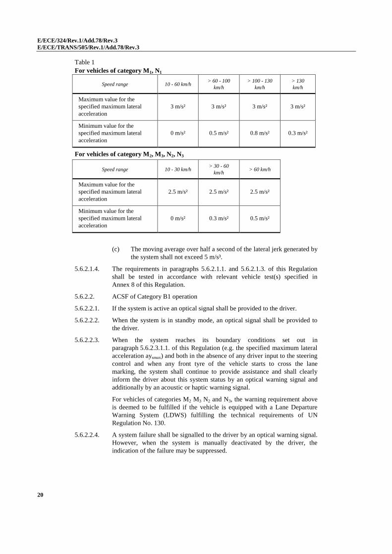
(b) The specified maximum lateral acceleration aysmax shall be within the
limits as defined in the following table:
E/ECE/324/Rev.1/Add.78/Rev.3
E/ECE/TRANS/505/Rev.1/Add.78/Rev.3
20
Table 1
For vehicles of category M1, N1
Speed range 10 - 60 km/h > 60 - 100
km/h
> 100 - 130
km/h
> 130
km/h
Maximum value for the
specified maximum lateral
acceleration
3 m/s² 3 m/s² 3 m/s² 3 m/s²
Minimum value for the
specified maximum lateral
acceleration
0 m/s² 0.5 m/s² 0.8 m/s² 0.3 m/s²
For vehicles of category M2, M3, N2, N3
Speed range 10 - 30 km/h > 30 - 60
km/h > 60 km/h
Maximum value for the
specified maximum lateral
acceleration
2.5 m/s² 2.5 m/s² 2.5 m/s²
Minimum value for the
specified maximum lateral
acceleration
0 m/s² 0.3 m/s² 0.5 m/s²
(c) The moving average over half a second of the lateral jerk generated by
the system shall not exceed 5 m/s³.
5.6.2.1.4. The requirements in paragraphs 5.6.2.1.1. and 5.6.2.1.3. of this Regulation
shall be tested in accordance with relevant vehicle test(s) specified in
Annex 8 of this Regulation.
5.6.2.2. ACSF of Category B1 operation
5.6.2.2.1. If the system is active an optical signal shall be provided to the driver.
5.6.2.2.2. When the system is in standby mode, an optical signal shall be provided to
the driver.
5.6.2.2.3. When the system reaches its boundary conditions set out in
paragraph 5.6.2.3.1.1. of this Regulation (e.g. the specified maximum lateral
acceleration aysmax) and both in the absence of any driver input to the steering
control and when any front tyre of the vehicle starts to cross the lane
marking, the system shall continue to provide assistance and shall clearly
inform the driver about this system status by an optical warning signal and
additionally by an acoustic or haptic warning signal.
For vehicles of categories M2 M3 N2 and N3, the warning requirement above
is deemed to be fulfilled if the vehicle is equipped with a Lane Departure
Warning System (LDWS) fulfilling the technical requirements of UN
Regulation No. 130.
5.6.2.2.4. A system failure shall be signalled to the driver by an optical warning signal.
However, when the system is manually deactivated by the driver, the
indication of the failure may be suppressed.
E/ECE/324/Rev.1/Add.78/Rev.3
E/ECE/TRANS/505/Rev.1/Add.78/Rev.3
21
5.6.2.2.5. When the system is active and in the speed range between 10 km/h or Vsmin,
whichever is higher, and Vsmax, it shall provide a means of detecting that the
driver is holding the steering control.
If, after a period of no longer than 15 seconds the driver is not holding the
steering control, an optical warning signal shall be provided. This signal may
be the same as the signal specified below in this paragraph.
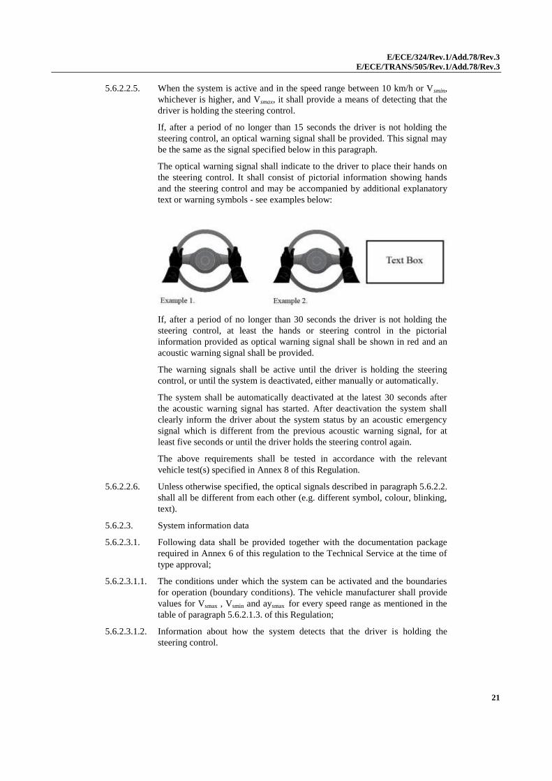
The optical warning signal shall indicate to the driver to place their hands on
the steering control. It shall consist of pictorial information showing hands
and the steering control and may be accompanied by additional explanatory
text or warning symbols - see examples below:
If, after a period of no longer than 30 seconds the driver is not holding the
steering control, at least the hands or steering control in the pictorial
information provided as optical warning signal shall be shown in red and an
acoustic warning signal shall be provided.
The warning signals shall be active until the driver is holding the steering
control, or until the system is deactivated, either manually or automatically.
The system shall be automatically deactivated at the latest 30 seconds after
the acoustic warning signal has started. After deactivation the system shall
clearly inform the driver about the system status by an acoustic emergency
signal which is different from the previous acoustic warning signal, for at
least five seconds or until the driver holds the steering control again.
The above requirements shall be tested in accordance with the relevant
vehicle test(s) specified in Annex 8 of this Regulation.
5.6.2.2.6. Unless otherwise specified, the optical signals described in paragraph 5.6.2.2.
shall all be different from each other (e.g. different symbol, colour, blinking,
text).
5.6.2.3. System information data
5.6.2.3.1. Following data shall be provided together with the documentation package
required in Annex 6 of this regulation to the Technical Service at the time of
type approval;
5.6.2.3.1.1. The conditions under which the system can be activated and the boundaries
for operation (boundary conditions). The vehicle manufacturer shall provide
values for Vsmax , Vsmin and aysmax for every speed range as mentioned in the
table of paragraph 5.6.2.1.3. of this Regulation;
5.6.2.3.1.2. Information about how the system detects that the driver is holding the
steering control.
E/ECE/324/Rev.1/Add.78/Rev.3
E/ECE/TRANS/505/Rev.1/Add.78/Rev.3
22
6. Test provisions
6.1. General provisions
6.1.1. The test shall be conducted on a level surface affording good adhesion.
6.1.2. During the test(s), the vehicle shall be loaded to its technically permissible
maximum mass and its technically permissible maximum load on the steered
axle(s).
In the case of axles fitted with ASE, this test shall be repeated with the
vehicle loaded to its technically permissible maximum mass and the axle
equipped with ASE loaded to its maximum permissible mass.
6.1.3. Before the test begins, the tyre pressures shall be as prescribed by the
manufacturer for the mass specified in paragraph 6.1.2. when the vehicle is
stationary.
6.1.4. In the case of any systems that use electrical energy for part or all of the
energy supply, all performance tests shall be carried out under conditions of
actual or simulated electrical load of all essential systems or systems
components which share the same energy supply. Essential systems shall
comprise at least lighting systems, windscreen wipers, engine management
and braking systems.
6.2. Provisions for motor vehicles
6.2.1. It shall be possible to leave a curve with a radius of 50 m at a tangent without
unusual vibration in the steering equipment at the following speed:
Category M1 vehicles: 50 km/h;
Category M2, M3, N1, N2 and N3 vehicles: 40 km/h or the maximum design
speed if this is below the speeds given above.
6.2.2. When the vehicle is driven in a circle with its steered wheels at
approximately half lock and a constant speed of at least 10 km/h, the turning
circle shall remain the same or become larger if the steering control is
released.
6.2.3. During the measurement of control effort, forces with a duration of less than
0.2 seconds shall not be taken into account.
6.2.4. The measurement of steering efforts on motor vehicles with intact steering
equipment.
6.2.4.1. The vehicle shall be driven from straight ahead into a spiral at a speed of
10 km/h. The steering wheel control effort shall be measured at the nominal
radius of the steering control until the position of the steering control
corresponds to turning radius given in the table below for the particular
category of vehicle with intact steering. One steering movement shall be
made to the right and one to the left.
6.2.4.2. The maximum permitted steering time and the maximum permitted steering
control effort with intact steering equipment are given in the table below for
each category of vehicle.
6.2.5. The measurement of steering efforts on motor vehicles with a failure in the
steering equipment.
E/ECE/324/Rev.1/Add.78/Rev.3
E/ECE/TRANS/505/Rev.1/Add.78/Rev.3
23
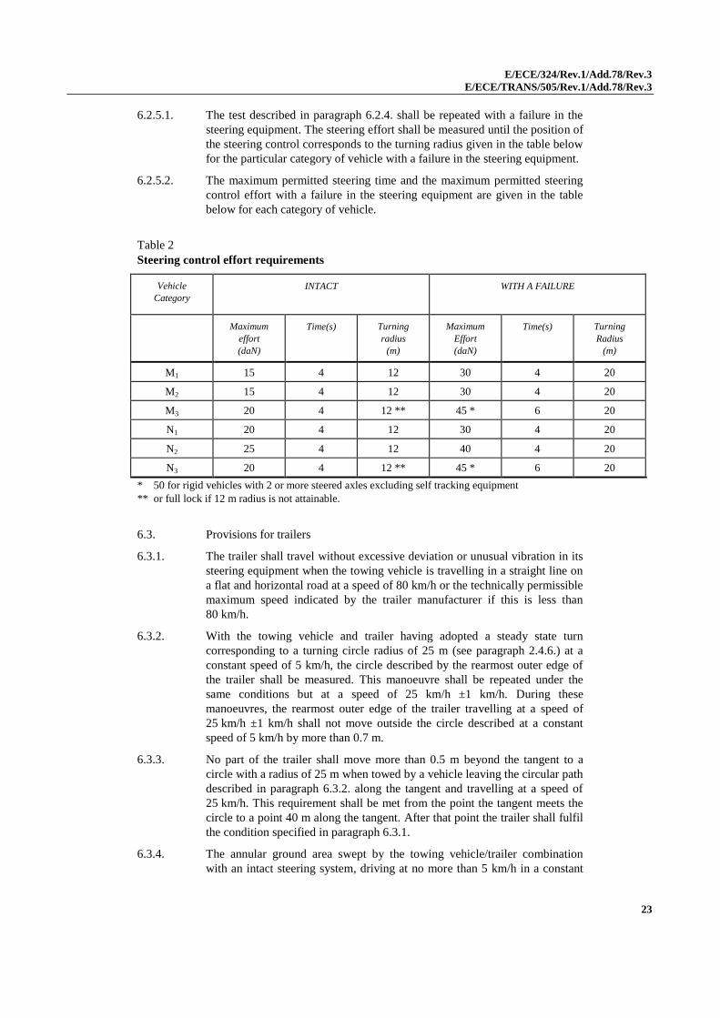
6.2.5.1. The test described in paragraph 6.2.4. shall be repeated with a failure in the
steering equipment. The steering effort shall be measured until the position of
the steering control corresponds to the turning radius given in the table below
for the particular category of vehicle with a failure in the steering equipment.
6.2.5.2. The maximum permitted steering time and the maximum permitted steering
control effort with a failure in the steering equipment are given in the table
below for each category of vehicle.
Table 2
Steering control effort requirements
Vehicle
Category
INTACT WITH A FAILURE
Maximum
effort
(daN)
Time(s) Turning
radius
(m)
Maximum
Effort
(daN)
Time(s)
Turning
Radius
(m)
M1 15 4 12 30 4 20
M2 15 4 12 30 4 20
M3 20 4 12 ** 45 * 6 20
N1 20 4 12 30 4 20
N2 25 4 12 40 4 20
N3 20 4 12 ** 45 * 6 20
* 50 for rigid vehicles with 2 or more steered axles excluding self tracking equipment
** or full lock if 12 m radius is not attainable.
6.3. Provisions for trailers
6.3.1. The trailer shall travel without excessive deviation or unusual vibration in its
steering equipment when the towing vehicle is travelling in a straight line on
a flat and horizontal road at a speed of 80 km/h or the technically permissible
maximum speed indicated by the trailer manufacturer if this is less than
80 km/h.
6.3.2. With the towing vehicle and trailer having adopted a steady state turn
corresponding to a turning circle radius of 25 m (see paragraph 2.4.6.) at a
constant speed of 5 km/h, the circle described by the rearmost outer edge of
the trailer shall be measured. This manoeuvre shall be repeated under the
same conditions but at a speed of 25 km/h ±1 km/h. During these
manoeuvres, the rearmost outer edge of the trailer travelling at a speed of
25 km/h ±1 km/h shall not move outside the circle described at a constant
speed of 5 km/h by more than 0.7 m.
6.3.3. No part of the trailer shall move more than 0.5 m beyond the tangent to a
circle with a radius of 25 m when towed by a vehicle leaving the circular path
described in paragraph 6.3.2. along the tangent and travelling at a speed of
25 km/h. This requirement shall be met from the point the tangent meets the
circle to a point 40 m along the tangent. After that point the trailer shall fulfil
the condition specified in paragraph 6.3.1.
6.3.4. The annular ground area swept by the towing vehicle/trailer combination
with an intact steering system, driving at no more than 5 km/h in a constant
E/ECE/324/Rev.1/Add.78/Rev.3
E/ECE/TRANS/505/Rev.1/Add.78/Rev.3
24
radius circle with the front outer corner of the towing vehicle describing a
radius of 0.67 x vehicle combination length but not less than 12.5 m is to be
measured.
6.3.4.1. If, with a fault in the steering system, the measured swept annular width is
> 8.3 m, then this shall not be an increase of more than 15 per cent compared
with the corresponding value measured with the intact steering system. There
shall not be any increase in the outer radius of the swept annular width.
6.3.5. The tests described in paragraphs 6.3.2., 6.3.3. and 6.3.4. shall be conducted
in both clockwise and anti-clockwise directions.
7. Conformity of production
The Conformity of Production Procedures shall comply with those set out in
the 1958 Agreement, Schedule 1 (E/ECE/TRANS/505/Rev.3) with the
following requirements:
7.1. The holder of the approval shall ensure that results of the conformity of
production tests are recorded and that the annexed documents remain
available for a period determined in agreement with the Type Approval
Authority or Technical Service. This period shall not exceed 10 years
counted from the time when production is definitively discontinued;
7.2. The Type Approval Authority or Technical Service which has granted type
approval may at any time verify the conformity control methods applied in
each production facility. The normal frequency of these verifications shall be
once every two years.
8. Penalties for non-conformity of production
8.1. The approval granted in respect of a vehicle type pursuant to this Regulation
may be withdrawn if the requirement laid down in paragraph 7.1. is not
complied with or if sample vehicles fail to comply with the requirements of
paragraph 6. of this Regulation.
8.2. If a Contracting Party to the Agreement applying this Regulation withdraws
an approval it has previously granted, it shall forthwith so notify the other
Contracting Parties applying this Regulation, by means of a communication
form conforming to the model in Annex 1 to this Regulation.
9. Modification and extension of approval of the vehicle type
9.1. Every modification of the vehicle type shall be notified to the Type Approval
Authority which granted the approval. The Type Approval Authority may
then either:
9.1.1. Consider that the modifications made are unlikely to have an appreciable
adverse effect and that in any case the vehicle still complies with the
requirements; or
9.1.2. Require a further test report from the Technical Service responsible for
conducting the tests.
E/ECE/324/Rev.1/Add.78/Rev.3
E/ECE/TRANS/505/Rev.1/Add.78/Rev.3
25
9.2. Confirmation or extension or refusal of approval, specifying the alterations,
shall be communicated by the procedure specified in paragraph 4.3. to the
Parties to this Regulation.
9.3. The Type Approval Authority issuing the extension of approval shall assign a
series number for such an extension and inform there of the other Parties to
the 1958 Agreement applying this Regulation by means of a communication
form conforming to the model in Annex 1 to this Regulation.
10. Production definitively discontinued
If the holder of the approval completely ceases to manufacture a type of
vehicle approved in accordance with this Regulation, he shall so inform the
Type Approval Authority which granted the approval. Upon receiving the
relevant communication that Type Approval Authority shall inform thereof
the other Parties to the 1958 Agreement applying this Regulation by means of
a communication form conforming to the model in Annex 1 to this
Regulation.
11. Names and addresses of technical series responsible for conducting approval tests and of Type Approval Authorities
The Parties to the 1958 Agreement applying this Regulation shall
communicate to the United Nations Secretariat the names and addresses of
the Technical Services responsible for conducting approval tests and of the
Type Approval Authorities which grant approval and to which forms
certifying approval or extension or refusal or withdrawal of approval, issued
in other countries, are to be sent.
12. Transitional provisions
12.1. As from the official date of entry into force of the 02 series of amendments,
no Contracting Party applying this Regulation shall refuse to grant or refuse
to accept type approvals under this Regulation as amended by the 02 series of
amendments.
12.2. As from 1 April 2018, Contracting Parties applying this Regulation shall
grant type approvals only if the vehicle type to be approved meets the
requirements of this Regulation as amended by the 02 series of amendments.
12.3. As from 1 April 2021, Contracting Parties applying this Regulation shall not
be obliged to accept, for the purpose of national or regional type approval, a
vehicle type approved to the preceding series of amendments to this
Regulation.
12.4. Contracting Parties applying this Regulation shall not refuse to grant
extensions of type approvals for existing types, which have been granted
according to the preceding series of amendments to this Regulation.
12.5. Notwithstanding paragraph 12.3., type approvals to the preceding series of
amendments to the Regulation, which are not affected by the 02 series of
E/ECE/324/Rev.1/Add.78/Rev.3
E/ECE/TRANS/505/Rev.1/Add.78/Rev.3
26
amendments shall remain valid and Contracting Parties applying the
Regulation shall continue to accept them.
12.6. As a derogation to paragraph 12.2., until 1 April 2020, type approvals may be
granted to new vehicle types not complying with the red colour for the hands-
off warning signal, mandated in paragraph 5.6.2.2.5., and having multi-
information displays installed in the instrument cluster not capable of
indicating red waning signals or using standalone tell-tales only.
E/ECE/324/Rev.1/Add.78/Rev.3
E/ECE/TRANS/505/Rev.1/Add.78/Rev.3
Annex 1
27
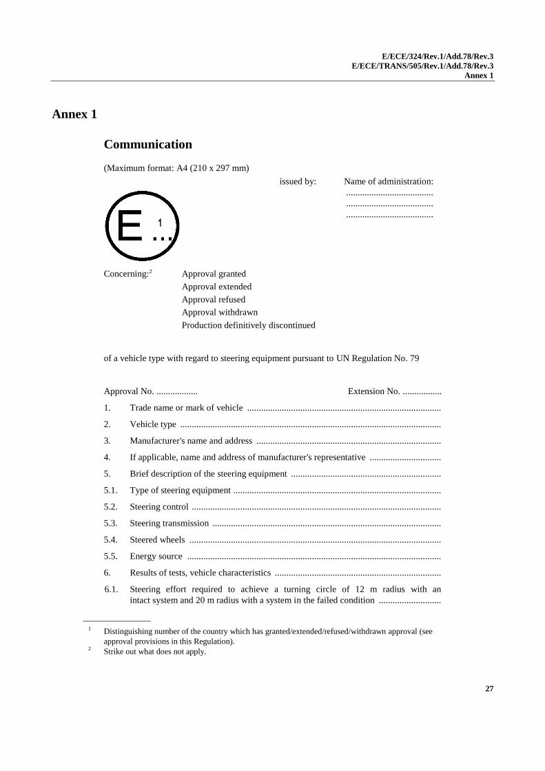
Annex 1
Communication
(Maximum format: A4 (210 x 297 mm)
1
Concerning:2 Approval granted
Approval extended
Approval refused
Approval withdrawn
Production definitively discontinued
of a vehicle type with regard to steering equipment pursuant to UN Regulation No. 79
Approval No. .................. Extension No. .................
1. Trade name or mark of vehicle ....................................................................................
2. Vehicle type .................................................................................................................
3. Manufacturer's name and address ................................................................................
4. If applicable, name and address of manufacturer's representative ...............................
5. Brief description of the steering equipment .................................................................
5.1. Type of steering equipment ..........................................................................................
5.2. Steering control ............................................................................................................
5.3. Steering transmission ...................................................................................................
5.4. Steered wheels .............................................................................................................
5.5. Energy source ..............................................................................................................
6. Results of tests, vehicle characteristics ........................................................................
6.1. Steering effort required to achieve a turning circle of 12 m radius with an
intact system and 20 m radius with a system in the failed condition ...........................
1 Distinguishing number of the country which has granted/extended/refused/withdrawn approval (see
approval provisions in this Regulation).
2 Strike out what does not apply.
1
issued by: Name of administration:
......................................
......................................
......................................
E/ECE/324/Rev.1/Add.78/Rev.3
E/ECE/TRANS/505/Rev.1/Add.78/Rev.3
Annex 1
28
6.1.1. Under normal conditions ..............................................................................................
6.1.2. After failure of special equipment ................................................................................
6.2. Other tests required by this Regulation .......................................................... pass/fail2
6.3. Adequate documentation in accordance with Annex 6 was supplied in respect
of the following parts of the steering system: ..............................................................
7. Applicable only to towing vehicles
7.1. The towing vehicle is/is not2 equipped with an electrical connector fulfilling the
relevant requirements of Annex 7
7.2. The maximum current available is ............................................................................ A3
8. Applicable only to trailers
8.1. The steering system of the trailer fulfils the relevant provisions of Annex 7 to UN
Regulation No. 79 ........................................................................................... Yes/No2
8.2. The maximum current required for the trailer steering system is ............................. A3
8.3. The trailer steering system is/is not2 able to supply auxiliary equipment on the
trailer with electrical energy.
9. Vehicle submitted for approval on ................................................................................
10. Technical Service responsible for conducting approval tests .......................................
11. Date of report issued by that service .............................................................................
12. Number of report issued by that service ........................................................................
13. Approval granted/extended/refused/withdrawn2
14. Position of approval mark on vehicle............................................................................
15. Place ..............................................................................................................................
16. Date ...............................................................................................................................
17. Signature .......................................................................................................................
18. Annexed to this communication is a list of documents in the approval file deposited
at the administration services having delivered the approval and which can be
obtained upon request.
3 As defined by the vehicle manufacturer – see paragraphs 2.3. and 3.1. of Annex 7 as appropriate.
E/ECE/324/Rev.1/Add.78/Rev.3
E/ECE/TRANS/505/Rev.1/Add.78/Rev.3
Annex 2
29
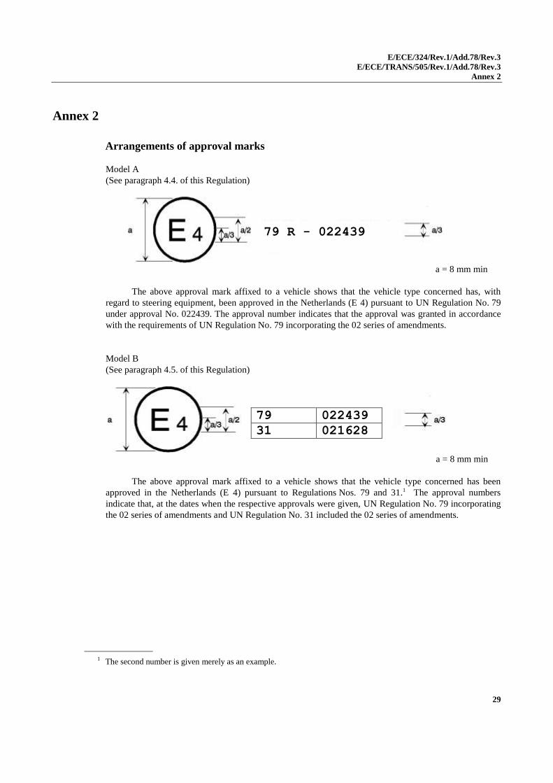
Annex 2
Arrangements of approval marks
Model A
(See paragraph 4.4. of this Regulation)
a = 8 mm min
The above approval mark affixed to a vehicle shows that the vehicle type concerned has, with
regard to steering equipment, been approved in the Netherlands (E 4) pursuant to UN Regulation No. 79
under approval No. 022439. The approval number indicates that the approval was granted in accordance
with the requirements of UN Regulation No. 79 incorporating the 02 series of amendments.
Model B
(See paragraph 4.5. of this Regulation)
a = 8 mm min
The above approval mark affixed to a vehicle shows that the vehicle type concerned has been
approved in the Netherlands (E 4) pursuant to Regulations Nos. 79 and 31.1 The approval numbers
indicate that, at the dates when the respective approvals were given, UN Regulation No. 79 incorporating
the 02 series of amendments and UN Regulation No. 31 included the 02 series of amendments.
1 The second number is given merely as an example.
79 022439
31 021628
79 R - 022439
E/ECE/324/Rev.1/Add.78/Rev.3
E/ECE/TRANS/505/Rev.1/Add.78/Rev.3
Annex 3
30
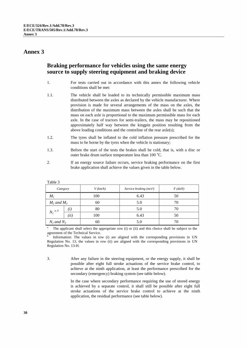
Annex 3
Braking performance for vehicles using the same energy source to supply steering equipment and braking device
1. For tests carried out in accordance with this annex the following vehicle
conditions shall be met:
1.1. The vehicle shall be loaded to its technically permissible maximum mass
distributed between the axles as declared by the vehicle manufacturer. Where
provision is made for several arrangements of the mass on the axles, the
distribution of the maximum mass between the axles shall be such that the
mass on each axle is proportional to the maximum permissible mass for each
axle. In the case of tractors for semi-trailers, the mass may be repositioned
approximately half way between the kingpin position resulting from the
above loading conditions and the centreline of the rear axle(s);
1.2. The tyres shall be inflated to the cold inflation pressure prescribed for the
mass to be borne by the tyres when the vehicle is stationary;
1.3. Before the start of the tests the brakes shall be cold, that is, with a disc or
outer brake drum surface temperature less than 100 oC.
2. If an energy source failure occurs, service braking performance on the first
brake application shall achieve the values given in the table below.
Table 3
Category V (km/h) Service braking (m/s²) F (daN)
M1 100 6.43 50
M2 and M3 60 5.0 70
N1 a, b
(i) 80 5.0 70
(ii) 100 6.43 50
N2 and N3 60 5.0 70
a The applicant shall select the appropriate row (i) or (ii) and this choice shall be subject to the
agreement of the Technical Service. b Information: The values in row (i) are aligned with the corresponding provisions in UN
Regulation No. 13, the values in row (ii) are aligned with the corresponding provisions in UN Regulation No. 13-H.
3. After any failure in the steering equipment, or the energy supply, it shall be
possible after eight full stroke actuations of the service brake control, to
achieve at the ninth application, at least the performance prescribed for the
secondary (emergency) braking system (see table below).
In the case where secondary performance requiring the use of stored energy
is achieved by a separate control, it shall still be possible after eight full
stroke actuations of the service brake control to achieve at the ninth
application, the residual performance (see table below).
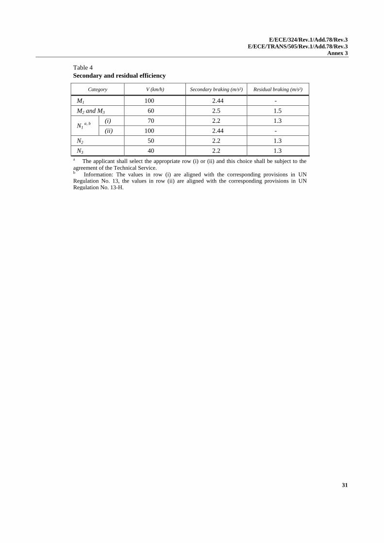
E/ECE/324/Rev.1/Add.78/Rev.3
E/ECE/TRANS/505/Rev.1/Add.78/Rev.3
Annex 3
31
Table 4
Secondary and residual efficiency
Category V (km/h) Secondary braking (m/s²) Residual braking (m/s²)
M1 100 2.44 -
M2 and M3 60 2.5 1.5
N1 a, b
(i) 70 2.2 1.3
(ii) 100 2.44 -
N2 50 2.2 1.3
N3 40 2.2 1.3
a The applicant shall select the appropriate row (i) or (ii) and this choice shall be subject to the
agreement of the Technical Service. b Information: The values in row (i) are aligned with the corresponding provisions in UN Regulation No. 13, the values in row (ii) are aligned with the corresponding provisions in UN Regulation No. 13-H.
E/ECE/324/Rev.1/Add.78/Rev.3
E/ECE/TRANS/505/Rev.1/Add.78/Rev.3
Annex 4
32
Annex 4
Additional provisions for vehicles equipped with Auxiliary Steering Equipment
1. General Provisions
Vehicles fitted with Auxiliary Steering Equipment (ASE) in addition to the
requirements given in the body of this Regulation shall also comply with the
provisions of this annex.
2. Specific Provisions
2.1. Transmission
2.1.1. Mechanical steering transmissions
Paragraph 5.3.1.1. of this Regulation applies.
2.1.2. Hydraulic steering transmissions
The hydraulic steering transmission shall be protected from exceeding the
maximum permitted service pressure T.
2.1.3. Electric steering transmissions
The electric steering transmission shall be protected from excess energy
supply.
2.1.4. Combination of steering transmissions
A combination of mechanical, hydraulic and electric transmissions shall
comply with the requirements specified in paragraphs 2.1.1., 2.1.2. and 2.1.3.
above.
2.2. Testing requirements for failure
2.2.1. Malfunction or failure of any part of the ASE (except for parts not considered
to the susceptible to breakdown as specified in paragraph 5.3.1.1. of this
Regulation) shall not result in a sudden significant change in vehicle
behaviour and the relevant requirements of paragraph 6. of this Regulation
shall still be met. Furthermore, it shall be possible to control the vehicle
without abnormal steering correction. This shall be verified by the following
tests:
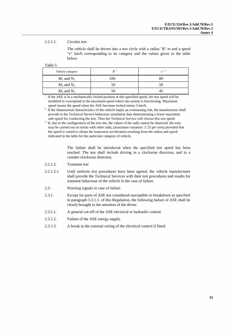
E/ECE/324/Rev.1/Add.78/Rev.3
E/ECE/TRANS/505/Rev.1/Add.78/Rev.3
Annex 4
33
2.2.1.1. Circular test
The vehicle shall be driven into a test circle with a radius "R" m and a speed
"v" km/h corresponding to its category and the values given in the table
below:
Table 5
Vehicle category R 3 v 1, 2
M1 and N1 100 80
M2 and N2 50 50
M3 and N3 50 45 1 If the ASE is in a mechanically locked position at this specified speed, the test speed will be
modified to correspond to the maximum speed where the system is functioning. Maximum
speed means the speed when the ASE becomes locked minus 5 km/h. 2 If the dimensional characteristics of the vehicle imply an overturning risk, the manufacturer shall
provide to the Technical Service behaviour simulation data demonstrating a lower maximum
safe speed for conducting the test. Then the Technical Service will choose this test speed. 3 If, due to the configuration of the test site, the values of the radii cannot be observed, the tests
may be carried out on tracks with other radii, (maximum variation: 25 per cent) provided that
the speed is varied to obtain the transverse acceleration resulting from the radius and speed
indicated in the table for the particular category of vehicle.
The failure shall be introduced when the specified test speed has been
reached. The test shall include driving in a clockwise direction, and in a
counter-clockwise direction.
2.2.1.2. Transient test
2.2.1.2.1. Until uniform test procedures have been agreed, the vehicle manufacturer
shall provide the Technical Services with their test procedures and results for
transient behaviour of the vehicle in the case of failure.
2.3. Warning signals in case of failure.
2.3.1. Except for parts of ASE not considered susceptible to breakdown as specified
in paragraph 5.3.1.1. of this Regulation, the following failure of ASE shall be
clearly brought to the attention of the driver.
2.3.1.1. A general cut-off of the ASE electrical or hydraulic control.
2.3.1.2. Failure of the ASE energy supply.
2.3.1.3. A break in the external wiring of the electrical control if fitted.
E/ECE/324/Rev.1/Add.78/Rev.3
E/ECE/TRANS/505/Rev.1/Add.78/Rev.3
Annex 5
34
Annex 5
Provisions for trailers having hydraulic steering transmissions
1. General provisions
Vehicles fitted with hydraulic steering transmission, in addition to the
requirements given in the body of this Regulation shall also comply with the
provisions of this annex.
2. Specific provisions
2.1. Performance of hydraulic lines and hose assemblies.
2.1.1. The hydraulic lines of hydraulic transmission shall be capable of a burst
pressure at least four times the maximum normal service pressure (T)
specified by the vehicle manufacturer. Hose assemblies shall comply with
ISO Standards 1402:1994, 6605:1986 and 7751:1991.
2.2. In systems dependent on an energy supply;
2.2.1. The energy supply shall be protected from excess pressure by a pressure
limiting valve which operates at the pressure T.
2.3. Protection of steering transmission;
2.3.1. The steering transmission shall be protected from excess pressure by a pressure
limiting valve which operates at between 1.1 T and 2.2 T. The operating pressure
of the pressure limiting valve shall be of a value that is compatible with the
operating characteristics of the steering system installed on the vehicle. This shall
be confirmed by the vehicle manufacturer at the time of type approval.
E/ECE/324/Rev.1/Add.78/Rev.3
E/ECE/TRANS/505/Rev.1/Add.78/Rev.3
Annex 6
35
Annex 6
Special requirements to be applied to the safety aspects of complex electronic vehicle control systems
1. General
This annex defines the special requirements for documentation, fault strategy
and verification with respect to the safety aspects of Complex Electronic
Vehicle Control Systems (paragraph 2.3. below) as far as this Regulation is
concerned.
This annex may also be called, by special paragraphs in this Regulation, for
safety related functions which are controlled by electronic system(s).
This annex does not specify the performance criteria for "The System" but
covers the methodology applied to the design process and the information
which shall be disclosed to the Technical Service, for type approval purposes.
This information shall show that "The System" respects, under normal and
fault conditions, all the appropriate performance requirements specified
elsewhere in this Regulation.
2. Definitions
For the purposes of this annex,
2.1. "Safety concept" is a description of the measures designed into the system,
for example within the electronic units, so as to address system integrity and
thereby ensure safe operation even in the event of an electrical failure. The
possibility of a fall-back to partial operation or even to a back-up system for
vital vehicle functions may be a part of the safety concept.
2.2. "Electronic control system" means a combination of units, designed to co-
operate in the production of the stated vehicle control function by electronic
data processing. Such systems, often controlled by software, are built from
discrete functional components such as sensors, electronic control units and
actuators and connected by transmission links. They may include mechanical,
electro-pneumatic or electro-hydraulic elements. "The System", referred to
herein, is the one for which type approval is being sought.
2.3. "Complex electronic vehicle control systems" are those electronic control
systems which are subject to a hierarchy of control in which a controlled
function may be over-ridden by a higher level electronic control
system/function. A function which is over-ridden becomes part of the
complex system.
2.4. "Higher-Level control" systems/functions are those which employ additional
processing and/or sensing provisions to modify vehicle behaviour by
commanding variations in the normal function(s) of the vehicle control
system. This allows complex systems to automatically change their
objectives with a priority which depends on the sensed circumstances.
2.5. "Units" are the smallest divisions of system components which will be
considered in this annex, since these combinations of components will be
E/ECE/324/Rev.1/Add.78/Rev.3
E/ECE/TRANS/505/Rev.1/Add.78/Rev.3
Annex 6
36
treated as single entities for purposes of identification, analysis or
replacement.
2.6. "Transmission links" are the means used for inter-connecting distributed units
for the purpose of conveying signals, operating data or an energy supply.
This equipment is generally electrical but may, in some part, be mechanical,
pneumatic or hydraulic.
2.7. "Range of control" refers to an output variable and defines the range over
which the system is likely to exercise control.
2.8. "Boundary of functional operation" defines the boundaries of the external
physical limits within which the system is able to maintain control.
3. Documentation
3.1. Requirements
The manufacturer shall provide a documentation package which gives access
to the basic design of "The System" and the means by which it is linked to
other vehicle systems or by which it directly controls output variables. The
function(s) of "The System" and the safety concept, as laid down by the
manufacturer, shall be explained. Documentation shall be brief, yet provide
evidence that the design and development has had the benefit of expertise
from all the system fields which are involved. For periodic technical
inspections, the documentation shall describe how the current operational
status of "The System" can be checked.
3.1.1. Documentation shall be made available in two parts:
(a) The formal documentation package for the approval, containing the
material listed in paragraph 3. (with the exception of that of
paragraph 3.4.4.) which shall be supplied to the Technical Service at
the time of submission of the type approval application. This will be
taken as the basic reference for the verification process set out in
paragraph 4. of this annex.
(b) Additional material and analysis data of paragraph 3.4.4. which shall
be retained by the manufacturer, but made open for inspection at the
time of type approval.
3.2. Description of the functions of "The System" A description shall be provided
which gives a simple explanation of all the control functions of "The System"
and the methods employed to achieve the objectives, including a statement of
the mechanism(s) by which control is exercised.
3.2.1. A list of all input and sensed variables shall be provided and the working
range of these defined.
3.2.2. A list of all output variables which are controlled by "The System" shall be
provided and an indication given, in each case, of whether the control is
direct or via another vehicle system. The range of control (paragraph 2.7.)
exercised on each such variable shall be defined.
3.2.3. Limits defining the boundaries of functional operation (paragraph 2.8.) shall
be stated where appropriate to system performance.
3.3. System layout and schematics
E/ECE/324/Rev.1/Add.78/Rev.3
E/ECE/TRANS/505/Rev.1/Add.78/Rev.3
Annex 6
37
3.3.1. Inventory of components.
A list shall be provided, collating all the units of "The System" and
mentioning the other vehicle systems which are needed to achieve the control
function in question.
An outline schematic showing these units in combination, shall be provided
with both the equipment distribution and the interconnections made clear.
3.3.2. Functions of the units
The function of each unit of "The System" shall be outlined and the signals
linking it with other units or with other vehicle systems shall be shown. This
may be provided by a labelled block diagram or other schematic, or by a
description aided by such a diagram.
3.3.3. Interconnections
Interconnections within "The System" shall be shown by a circuit diagram for
the electric transmission links, by a piping diagram for pneumatic or
hydraulic transmission equipment and by a simplified diagrammatic layout
for mechanical linkages.
3.3.4. Signal flow and priorities
There shall be a clear correspondence between these transmission links and
the signals carried between Units. Priorities of signals on multiplexed data
paths shall be stated wherever priority may be an issue affecting performance
or safety as far as this Regulation is concerned.
3.3.5. Identification of units
Each unit shall be clearly and unambiguously identifiable (e.g. by marking
for hardware and marking or software output for software content) to provide
corresponding hardware and documentation association.
Where functions are combined within a single unit or indeed within a single
computer, but shown in multiple blocks in the block diagram for clarity and
ease of explanation, only a single hardware identification marking shall be
used. The manufacturer shall, by the use of this identification, affirm that the
equipment supplied conforms to the corresponding document.
3.3.5.1. The identification defines the hardware and software version and, where the
latter changes such as to alter the function of the Unit as far as this
Regulation is concerned, this identification shall also be changed.
3.4. Safety concept of the manufacturer
3.4.1. The manufacturer shall provide a statement which affirms that the strategy
chosen to achieve "The System" objectives will not, under non-fault
conditions, prejudice the safe operation of systems which are subject to the
prescriptions of this Regulation.
3.4.2. In respect of software employed in "The System", the outline architecture
shall be explained and the design methods and tools used shall be identified.
The manufacturer shall be prepared, if required, to show some evidence of
the means by which they determined the realisation of the system logic,
during the design and development process.
E/ECE/324/Rev.1/Add.78/Rev.3
E/ECE/TRANS/505/Rev.1/Add.78/Rev.3
Annex 6
38
3.4.3. The Manufacturer shall provide the technical authorities with an explanation
of the design provisions built into "The System" so as to generate safe
operation under fault conditions. Possible design provisions for failure in
"The System" are for example:
(a) Fall-back to operation using a partial system.
(b) Change-over to a separate back-up system.
(c) Removal of the high level function.
In case of a failure, the driver shall be warned for example by warning signal
or message display. When the system is not deactivated by the driver, e.g. by
turning the ignition (run) switch to "off", or by switching off that particular
function if a special switch is provided for that purpose, the warning shall be
present as long as the fault condition persists.
3.4.3.1. If the chosen provision selects a partial performance mode of operation under
certain fault conditions, then these conditions shall be stated and the resulting
limits of effectiveness defined.
3.4.3.2. If the chosen provision selects a second (back-up) means to realise the
vehicle control system objective, the principles of the change-over
mechanism, the logic and level of redundancy and any built in back-up
checking features shall be explained and the resulting limits of back-up
effectiveness defined.
3.4.3.3. If the chosen provision selects the removal of the Higher Level Function, all
the corresponding output control signals associated with this function shall be
inhibited, and in such a manner as to limit the transition disturbance.
3.4.4. The documentation shall be supported, by an analysis which shows, in
overall terms, how the system will behave on the occurrence of any one of
those specified faults which will have a bearing on vehicle control
performance or safety.
This may be based on a Failure Mode and Effect Analysis (FMEA), a Fault
Tree Analysis (FTA) or any similar process appropriate to system safety
considerations.
The chosen analytical approach(es) shall be established and maintained by
the manufacturer and shall be made open for inspection by the Technical
Service at the time of the type approval.
3.4.4.1. This documentation shall itemize the parameters being monitored and shall
set out, for each fault condition of the type defined in paragraph 3.4.4. of this
annex, the warning signal to be given to the driver and/or to service/technical
inspection personnel.
4. Verification and test
4.1. The functional operation of "The System", as laid out in the documents
required in paragraph 3., shall be tested as follows:
4.1.1. Verification of the function of "The System"
As the means of establishing the normal operational levels, verification of the
performance of the vehicle system under non-fault conditions shall be
conducted against the manufacturer's basic benchmark specification unless
E/ECE/324/Rev.1/Add.78/Rev.3
E/ECE/TRANS/505/Rev.1/Add.78/Rev.3
Annex 6
39
this is subject to a specified performance test as part of the approval
procedure of this or another Regulation.
4.1.2. Verification of the safety concept of paragraph 3.4.
The reaction of "The System" shall, at the discretion of the Type Approval
Authority, be checked under the influence of a failure in any individual unit
by applying corresponding output signals to electrical units or mechanical
elements in order to simulate the effects of internal faults within the unit.
4.1.2.1. The verification results shall correspond with the documented summary of
the failure analysis, to a level of overall effect such that the safety concept
and execution are confirmed as being adequate.
E/ECE/324/Rev.1/Add.78/Rev.3
E/ECE/TRANS/505/Rev.1/Add.78/Rev.3
Annex 7
40
Annex 7
Special provisions for the powering of trailer steering systems from the towing vehicle
1. General
The requirements of this annex shall apply to towing vehicles and trailers
where electrical energy is supplied from the towing vehicle to facilitate
operation of the steering system installed on the trailer.
2. Requirements for towing vehicles
2.1. Energy Supply
2.1.1. The vehicle manufacturer shall define the capacity of the energy source that
will enable the current defined in paragraph 2.3. below to be available for the
trailer during normal operation of the vehicle.
2.1.2. The driver's manual shall include information to advise the driver on the
electrical energy available for the trailer steering system and that the
electrical interface shall not be connected when the current requirement
marked on the trailer exceeds that which can be supplied by the towing
vehicle.
2.1.3. The power supply provided by the connector referenced in paragraph 2.5.
below shall be used for the powering of the trailer steering system. However,
in all cases the provisions of paragraph 3.3. below shall apply.
2.2. The nominal operating voltage is 24V.
2.3. The maximum current supply available at the connector referenced in
paragraph 2.5.2. below shall be defined by the towing vehicle manufacturer.
2.4. Protection of the electrical system
2.4.1. The electrical system of the towing vehicle shall be protected from an
overload or short circuit in the supply to the trailer steering system.
2.5. Wiring and Connectors
2.5.1. The cables used to supply the trailer electrical energy shall have a conductor
cross-sectional area compatible with the continuous current defined in
paragraph 2.3. above.
2.5.2. Until a uniform standard has been defined the connector used to connect to
the trailer shall fulfil the following:
(a) The pins shall have a current carrying capacity compatible with the
maximum continuous current defined in paragraph 2.3. above;
(b) Until uniform standards have been agreed the environmental
protection of the connector shall be appropriate to the application and
included in the Annex 6 assessment; and
E/ECE/324/Rev.1/Add.78/Rev.3
E/ECE/TRANS/505/Rev.1/Add.78/Rev.3
Annex 7
41
(c) The connector shall not be interchangeable with an existing electrical
connector currently used on the towing vehicle i.e. ISO 7638,
ISO 12098, etc.
2.6. Marking
2.6.1. The towing vehicle shall be marked to indicate the maximum current
available for the trailer as defined in paragraph 2.3. above.
The marking shall be indelible and positioned so that it is visible when
connecting the electrical interface referenced in paragraph 2.5.2. above.
3. Requirements for trailers
3.1. The maximum current requirement of the trailer steering system shall be
defined by the vehicle manufacturer.
3.2. The nominal operating voltage is 24V.
3.3. The electrical energy available from the towing vehicle shall only be used as
follows:
(a) Exclusively for use by the trailer steering system;
or
(b) For the trailer steering system and to power auxiliary systems on the
trailer provided the steering system has priority and is protected from
an overload external to the steering system. This protection shall be a
function of the trailer steering system.
3.4. Wiring and Connectors
3.4.1. The cables used to supply the trailer steering system with electrical energy
shall have a conductor cross sectional area compatible with the energy
requirements of the steering system installed on the trailer.
3.4.2. Until a uniform standard has been defined the connector used to connect to
the trailer shall fulfil the following:
(a) The pins shall have a current carrying capacity compatible with the
maximum current defined by the vehicle manufacturer in
paragraph 3.1. above;
(b) Until uniform standards have been agreed the environmental
protection of the connector shall be appropriate to the application and
included in the Annex 6 assessment;
(c) The connector shall not be interchangeable with an existing electrical
connector currently used on the towing vehicle, i.e. ISO 7638,
ISO 12098, etc.
3.5. Failure warning:
Failures within the electric control transmission of the steering system shall
be directly displayed to the driver.
3.6. Demonstration of the operation of the steering system
3.6.1. At the time of type approval the trailer manufacturer shall demonstrate to the
Technical Service the functionality of the steering system by fulfilling the
relevant performance requirements specified within the Regulation.
E/ECE/324/Rev.1/Add.78/Rev.3
E/ECE/TRANS/505/Rev.1/Add.78/Rev.3
Annex 7
42
3.6.2. Failure Conditions:
3.6.2.1. Under steady state conditions:
In the event of the trailer being coupled to a towing vehicle that does not have
an electrical supply for the trailer steering system, or there is a break in the
electrical supply to the trailer steering system or there is a failure in the
electric control transmission of the trailer steering control system it shall be
demonstrated that the trailer fulfils all relevant requirements of paragraph 6.3.
of the Regulation for the intact system.
3.6.2.2. Under transient conditions
The transient behaviour of the vehicle in the case of failure within the electric
control transmission of the steering system shall be evaluated to ensure
vehicle stability is maintained during the transition following the failure and
shall be assessed by fulfilling the following:
(a) By applying the test procedure and requirements defined within
paragraph 6.3.1. of the Regulation.1
(b) By applying the test procedure and requirements defined within
paragraph 6.3.3. of the Regulation.1
3.6.3. If the trailer steering system utilises hydraulic transmission to operate the
steering, the requirements of Annex 5 shall apply.
3.7. Marking
3.8.1. Trailers equipped with a connector for the supply of electrical energy to the
trailer steering system shall be marked to include the following information:
(a) The maximum current requirement for the trailer steering system as
defined in paragraph 3.1. above.
(b) The functionality of the trailer steering system including the impact on
manoeuvrability when the connector is connected and disconnected.
The marking shall be in indelible form and positioned so that it is visible
when connecting to the electrical interface referenced in paragraph 3.3.2.
above.
1 The Technical Service may accept the test results supplied by the trailer manufacturer to demonstrate
compliance with the transient tests
E/ECE/324/Rev.1/Add.78/Rev.3
E/ECE/TRANS/505/Rev.1/Add.78/Rev.3
Annex 8
43
Annex 8
Test requirements for corrective and automatically commanded steering functions
1. General provisions
Vehicles fitted with CSF and/or ACSF systems shall fulfil the appropriate
tests requirements of this annex.
2. Testing conditions
The tests shall be performed on a flat, dry asphalt or concrete surface
affording good adhesion. The ambient temperature shall be between 0 °C and
45 °C.
2.1. Lane markings
The lane markings on the road used for the tests shall be in line with one of
those described in Annex 3 of UN Regulation No. 130. The markings shall be
in good condition and of a material conforming to the standard for visible
lane markings. The lane-marking layout used for the tests shall be recorded in
the test report.
The width of the lane shall be minimum 3.5 m, for the purpose of the tests of
this annex.
The test shall be performed under visibility conditions that allow safe driving
at the required test speed.
The vehicle manufacturer shall demonstrate, through the use of
documentation, compliance with all other lane markings identified in
Annex 3 of UN Regulation No. 130. Any of such documentation shall be
appended to the test report.
2.2. Tolerances
All vehicle speeds specified for the tests described in this annex shall be met
within a tolerance of ±2 km/h.
2.3. Vehicle conditions
2.3.1. Test mass
The vehicle shall be tested in a load condition agreed between the
manufacturer and the Technical Service. No load alteration shall be made
once the test procedure has begun. The vehicle manufacturer shall
demonstrate, through the use of documentation, that the system works at all
load conditions.
2.3.2. The vehicle shall be tested at the tyre pressures recommended by the vehicle
manufacturer.
2.4. Lateral acceleration
The position representing the centre of gravity, at which the lateral
acceleration shall be measured, shall be determined in agreement between the
E/ECE/324/Rev.1/Add.78/Rev.3
E/ECE/TRANS/505/Rev.1/Add.78/Rev.3
Annex 8
44
vehicle manufacturer and the Technical Service. This position shall be
identified in the test report.
The lateral acceleration shall be measured without taking into account the
additional effects due to the movements of the vehicle body (e.g. roll of
sprung mass).
3. Tests procedures
3.1. Tests for CSF
The following test applies to CSF functions defined in subparagraph (c) of
CSF definition in paragraph 2.3.4.2. of this Regulation.
3.1.1. Warning test for CSF
3.1.1.1. The vehicle shall be driven with an activated CSF on a road with lane
markings on each side of the lane. In case of a CSF whose interventions are
solely based on the evaluation of the presence and location of lane
boundaries, the vehicle shall be driven on a road delimited by the boundaries
as declared by the manufacturer (e.g. road edge).
The test conditions and the vehicle test speed shall be within the operating
range of the system.
During the test, the duration of the CSF interventions and of the optical and
acoustic warning signals shall be recorded.
In the case of paragraph 5.1.6.1.2.1. of this Regulation, the vehicle shall be
driven such that it attempts to leave the lane and causes CSF intervention to
be maintained for a period longer than 10 s (for M1, N1) or 30 s (for M2, M3,
N2, N3). If such a test cannot be practically achieved due to e.g. the
limitations of the test facilities, with the consent of the Type Approval
Authority this requirement may be fulfilled through the use of
documentation.
The test requirements are fulfilled if:
(a) The acoustic warning is provided no later than 10 s (for M1, N1) or
30 s (for M2, M3, N2, N3) after the beginning of the intervention.
In the case of paragraph 5.1.6.1.2.2. of this Regulation, the vehicle shall be
driven such that it attempts to leave the lane and causes at least three
interventions of the system within a rolling interval of 180 s.
The test requirements are fulfilled if:
(a) An optical warning signal is provided for each intervention, as long as
the intervention exists, and
(b) An acoustic warning signal is provided at the second and third
intervention, and
(c) The acoustic warning signal at the third intervention is at least 10 s
longer than the one at the second intervention.
3.1.1.2. In addition, the manufacturer shall demonstrate to the satisfaction of the
Technical Service that the requirements defined in paragraphs 5.1.6.1.1. and
5.1.6.1.2. are fulfilled in the whole range of CSF operation. This may be
E/ECE/324/Rev.1/Add.78/Rev.3
E/ECE/TRANS/505/Rev.1/Add.78/Rev.3
Annex 8
45
achieved on the basis of appropriate documentation appended to the test
report.
3.1.2 Overriding force test
3.1.2.1. The vehicle shall be driven with an activated CSF on a road with lane
markings on each side of the lane.
The test conditions and the vehicle test speed shall be within the operating
range of the system.
The vehicle shall be driven such that it attempts to leave the lane and causes
CSF intervention. During the intervention, the driver shall apply a force on
the steering control to override the intervention.
The force applied by the driver on the steering control to override the
intervention shall be recorded.
3.1.2.2. The test requirements are fulfilled if the force applied by the driver on the
steering control to override the intervention does not exceed 50 N.
3.1.2.3 In addition, the manufacturer shall demonstrate to the satisfaction of the
Technical Service that the requirements defined in paragraph 5.1.6.1.3. are
fulfilled in the whole range of CSF operation. This may be achieved on the
basis of appropriate documentation appended to the test report.
3.2. Tests for ACSF Category B1 Systems
3.2.1. Lane keeping functional test
3.2.1.1. The vehicle speed shall remain in the range from Vsmin up to Vsmax.
The test shall be carried out for each speed range specified in
paragraph 5.6.2.1.3. of this Regulation separately or within contiguous speed
ranges where the aysmax is identical.
The vehicle shall be driven without any force applied by the driver on the
steering control (e.g. by removing the hands from the steering control) with a
constant speed on a curved track with lane markings at each side.
The necessary lateral acceleration to follow the curve shall be between
80 and 90 per cent of the maximum lateral acceleration specified by the
vehicle manufacturer aysmax.
The lateral acceleration and the lateral jerk shall be recorded during the test.
3.2.1.2. The test requirements are fulfilled if:
The vehicle does not cross any lane marking;
The moving average over half a second of the lateral jerk does not exceed
5 m/s³.
3.2.1.3. The vehicle manufacturer shall demonstrate to the satisfaction of the
Technical Service that the requirements for the whole lateral acceleration and
speed range are fulfilled. This may be achieved on the basis of appropriate
documentation appended to the test report.
3.2.2. Maximum lateral acceleration test
3.2.2.1. The vehicle speed shall remain in the range from Vsmin up to Vsmax.
E/ECE/324/Rev.1/Add.78/Rev.3
E/ECE/TRANS/505/Rev.1/Add.78/Rev.3
Annex 8
46
The test shall be carried out for each speed range specified in
paragraph 5.6.2.1.3. of this Regulation separately or within contiguous speed
ranges where the aysmax is identical.
The vehicle shall be driven without any force applied by the driver on the
steering control (e.g. by removing the hands from the steering control) with a
constant speed on a curved track with lane markings at each side.
The Technical Service defines a test speed and a radius which would provoke
a higher acceleration than aysmax + 0.3 m/s2 (e.g. by travelling with a higher
speed through a curve with a given radius).
The lateral acceleration and the lateral jerk shall be recorded during the test.
3.2.2.2. The test requirements are fulfilled if:
The recorded acceleration is within the limits specified in
paragraph 5.6.2.1.3. of this Regulation.
The moving average over half a second of the lateral jerk does not exceed
5 m/s³.
3.2.3. Overriding force test
3.2.3.1. The vehicle speed shall remain in the range from Vsmin up to Vsmax.
The vehicle shall be driven without any force applied by the driver on the
steering control (e.g. by removing the hands from the steering control) with a
constant speed on a curved track with lane markings at each side.
The necessary lateral acceleration to follow the curve shall be between
80 and 90 per cent of the minimum value specified in the table of
paragraph 5.6.2.1.3. of this Regulation.
The driver shall then apply a force on the steering control to override the
system intervention and leave the lane.
The force applied by the driver on the steering control during the overriding
manoeuvre shall be recorded.
3.2.3.2. The test requirements are fulfilled if the force applied by the driver on the
steering control during the overriding manoeuvre is less than 50N.
The manufacturer shall demonstrate through appropriate documentation that
this condition is fulfilled throughout the ACSF operation range.
3.2.4. Transition test; hands-on test
3.2.4.1. The vehicle shall be driven with activated ACSF with a vehicle test speed
between Vsmin + 10 km/h and Vsmin + 20 km/h on a track with lane markings
at each side of the lane.
The driver shall release the steering control and continue to drive until the
ACSF is deactivated by the system. The track shall be selected such that it
allows driving with activated ACSF for at least 65 s without any driver
intervention.
The test shall be repeated with a vehicle test speed between Vsmax - 20 km/h
and Vsmax - 10 km/h or 130 km/h whichever is lower.
E/ECE/324/Rev.1/Add.78/Rev.3
E/ECE/TRANS/505/Rev.1/Add.78/Rev.3
Annex 8
47
Additionally, the vehicle manufacturer shall demonstrate to the satisfaction of
the Technical Service that the requirements for the whole speed range are
fulfilled. This may be achieved on the basis of appropriate documentation
appended to the test report.
3.2.4.2. The test requirements are fulfilled if:
The optical warning signal was given at the latest 15 s after the steering
control has been released and remains until ACSF is deactivated.
The acoustic warning signal was given at the latest 30 s after the steering
control has been released and remains until ACSF is deactivated.
The ACSF is deactivated at the latest 30 s after the acoustic warning signal
has started, with an acoustic emergency signal of at least 5 s, which is
different from the previous acoustic warning signal.