Embed Size (px)
Citation preview
GE.13-
Agreement
Concerning the Adoption of Uniform Technical Prescriptions for
Wheeled Vehicles, Equipment and Parts which can be Fitted and/or be
Used on Wheeled Vehicles and the Conditions for Reciprocal
Recognition of Approvals Granted on the Basis of these Prescriptions*
(Revision 2, including the amendments which entered into force on 16 October 1995)
Addendum 52: Regulation No. 53
Revision 3
Incorporating all valid text up to:
Supplement 9 to the 01 series of amendments - Date of entry into force: 15 October 2008
Supplement 10 to the 01 series of amendments - Date of entry into force: 24 October 2009
Corrigendum 1 to Supplement 10 to the 01 series of amendments - Date of entry into force:
11 November 2009
Supplement 11 to the 01 series of amendments - Date of entry into force: 9 December 2010
Supplement 12 to the 01 series of amendments - Date of entry into force: 23 June 2011
Supplement 13 to the 01 series of amendments - Date of entry into force: 28 October 2011
Supplement 14 to the 01 series of amendments - Date of entry into force: 15 July 2013
Uniform provisions concerning the approval of category L3 vehicles
with regard to the installation of lighting and light-signalling devices
UNITED NATIONS
* Former title of the Agreement: Agreement Concerning the Adoption of Uniform Conditions of
Approval and Reciprocal Recognition of Approval for Motor Vehicle Equipment and Parts, done at
Geneva on 20 March 1958.
E/ECE/324/Rev.1/Add.52/Rev.3−E/ECE/TRANS/505/Rev.1/Add.52/Rev.3
7 August 2013

E/ECE/324/Rev.1/Add.52/Rev.3
E/ECE/TRANS/505/Rev.1/Add.52/Rev.3
3
Regulation No. 53
Uniform provisions concerning the approval of category L3 vehicles with regard to the installation of lighting and light-signalling devices
Contents
Page
1. Scope ....................................................................................................................................... 4
2. Definitions ............................................................................................................................... 4
3. Application for approval .......................................................................................................... 8
4. Approval .................................................................................................................................. 9
5. General specifications .............................................................................................................. 10
6. Individual specifications .......................................................................................................... 14
7. Modifications of the vehicle type or of the installation of its lighting
and light-signalling devices ..................................................................................................... 30
8. Conformity of production ........................................................................................................ 30
9. Penalties for non-conformity of production ............................................................................. 31
10. Production definitively discontinued ....................................................................................... 31
11. Transitional provisions ............................................................................................................ 31
12. Names and addresses of Technical Services responsible for conducting approval tests,
and of Type Approval Authorities ........................................................................................... 31
Annexes
1 Communication........................................................................................................................ 32
2 Arrangement of approval marks .............................................................................................. 35
3 Lamp surfaces, axis and centre of reference, and angles of geometric visibility ..................... 36
4 Forward visibility of red lights and rearward visibility of white lights .................................... 38
5 Control of conformity of production ........................................................................................ 39
6 Explanation about "the horizontal inclination", "the bank angle" and the angle "δ" ............... 40
E/ECE/324/Rev.1/Add.52/Rev.3
E/ECE/TRANS/505/Rev.1/Add.52/Rev.3
4
1. Scope
This Regulation applies to vehicles of category L31 with regard to the
installation of lighting and light-signalling devices.
2. Definitions
For the purpose of this Regulation:
2.1. "Approval of a vehicle" means the approval of a vehicle type with regard to
the number and mode of installation of the lighting and light-signalling
devices;
2.2. "Vehicle type" means a category of vehicles which do not differ from each
other in such essential respects as:
2.2.1. The dimensions and external shape of the vehicle;
2.2.2. The number and position of the devices;
2.2.3. The following shall likewise not be deemed to be "vehicles of a different
type":
2.2.3.1. Vehicles which differ within the meaning of paragraphs 2.2.1. and 2.2.2.
above but not in such a way as to entail a change in the kind, number,
position and geometric visibility of the lamps prescribed for the vehicle type
in question; and
2.2.3.2. Vehicles on which lamps approved under one of the Regulations annexed to
the 1958 Agreement, or lamps allowed in the country in which the vehicles
are registered, are fitted, or are absent where their fitting is optional;
2.3. "Transverse plane" means a vertical plane perpendicular to the median
longitudinal plane of the vehicle;
2.4. "Unladen vehicle" means a vehicle without a driver, or passenger, and
unladen, but with its fuel tank full and its normal complement of tools;
2.5. "Lamp" means a device designed to illuminate the road or to emit a light
signal to other road users. Rear registration plate lamp and retro-reflectors are
likewise to be regarded as lamps;
2.5.1. "Equivalent lamps" means lamps having the same function and authorised in
the country in which the vehicle is registered; such lamps may have different
characteristics from those of the lamps with which the vehicle is equipped at
the time of approval, on condition that they satisfy the requirements of this
Regulation;
2.5.2. "Independent lamps" means devices having separate illuminating surfaces,
separate light sources and separate lamp bodies;
2.5.3. "Grouped lamps" means devices having separate illuminating surfaces and
separate light sources, but a common lamp body;
1 As defined in the Consolidated Resolution on the Construction of Vehicles (R.E.3.), document
ECE/TRANS/WP.29/78/Rev.2, para. 2. -
www.unece.org/trans/main/wp29/wp29wgs/wp29gen/wp29resolutions.html
E/ECE/324/Rev.1/Add.52/Rev.3
E/ECE/TRANS/505/Rev.1/Add.52/Rev.3
5
2.5.4. "Combined" means devices having separate illuminating surfaces, but a
common light source and a common lamp body;
2.5.5. "Reciprocally incorporated" means devices having separate light sources or a
single light source operating under different conditions (for example, optical,
mechanical, electrical differences), totally or partially common illuminating
surfaces and a common lamp body;
2.5.6. "Driving-beam (main-beam) headlamp" means the lamp used to illuminate
the road over a long distance ahead of the vehicle;
2.5.7. "Passing-beam (dipped-beam) headlamp" means the lamp used to illuminate
the road ahead of the vehicle without dazzling of causing undue discomfort to
oncoming drivers and other road users;
2.5.7.1. "Principal passing-beam (principal dipped beam)" means the dipped beam
produced without the contribution of infrared (IR) emitters and/or additional
light sources for bend lighting.
2.5.8. "Direction indicator lamp" means the lamp used to indicate to other road-
users that the driver intends to change direction to the right or to the left;
A direction indicator lamp or lamps may also be used according to provisions
of Regulation No. 97.
2.5.9. "Stop lamp" means the lamp used to indicate to other road-users to the rear of
the vehicle that its driver is applying the service brake;
2.5.10. "Rear-registration-plate illuminating device" means the device used to
illuminate the space reserved for the rear registration plate; such a device
may consist of several optical components;
2.5.11. "Front position lamp" means the lamp used to indicate the presence of the
vehicle when viewed from the front;
2.5.12. "Rear position lamp" means the lamp used to indicate the presence of the
vehicle when viewed from the rear;
2.5.13. "Retro-reflector" means a device used to indicate the presence of a vehicle by
the reflection of light emanating from a light source not connected to the
vehicle, the observer being situated near the source;
For the purpose of this Regulation, retro-reflecting number plates are not
considered as retro-reflectors;
2.5.14. "Hazard warning signal" means the simultaneous operation of all of a
vehicle's direction indicator lamps to show that the vehicle temporarily
constitutes a special danger to other road users;
2.5.15. "Front fog lamp" means the lamp used to improve the illumination of the
road in case of fog, snowfall, rainstorms or dust clouds;
2.5.16. "Rear fog lamp" means the lamp used to make the vehicle more easily visible
from the rear in dense fog;
2.5.17. "Daytime running lamp" means a lamp facing in a forward direction used to
make the vehicle more easily visible when driving during daytime.
2.6. "Light-emitting surface" of a "lighting device", "light-signalling device" or a
retro-reflector means all or part of the exterior surface of the transparent
material as declared in the request for approval by the manufacturer of the
device on the drawing, see Annex 3;
E/ECE/324/Rev.1/Add.52/Rev.3
E/ECE/TRANS/505/Rev.1/Add.52/Rev.3
6
2.7. "Illuminating surface" (see Annex 3);
2.7.1. "Illuminating surface of a lighting device" (paragraphs. 2.5.6., 2.5.7. and
2.5.15. above) means the orthogonal projection of the full aperture of the
reflector, or in the case of headlamps with an ellipsoidal reflector of the
"projection lens", on a transverse plane. If the lighting device has no
reflector, the definition of paragraph 2.7.2. below shall be applied. If the light
emitting surface of the lamp extends over part only of the full aperture of the
reflector, then the projection of that part only is taken into account.
In the case of a passing-beam headlamp, the illuminating surface is limited
by the apparent trace of the cut-off on to the lens. If the reflector and lens are
adjustable relative to one another, the mean adjustment should be used;
In the case where any combination of a headlamp producing the principal
passing-beam and additional lighting units or light sources designed to
produce bend lighting are operated together, the individual illuminating
surfaces, taken together, constitute the illuminating surface.
2.7.2. "Illuminating surface of a light-signalling device other than a retro-reflector"
(paragraphs 2.5.8., 2.5.9., 2.5.11., 2.5.12., 2.5.14. and 2.5.16. above) means
the orthogonal projection of the lamp in a plane perpendicular to its axis of
reference and in contact with the exterior light-emitting surface of the lamp,
this projection being bounded by the edges of screens situated in this plane,
each allowing only 98 per cent of the total luminous intensity of the light to
persist in the direction of the axis of reference. To determine the lower, upper
and lateral limits of the illuminating surface, only screens with horizontal or
vertical edges shall be used;
2.7.3. "Illuminating surface of a retro-reflector" (para. 2.5.13. above) means the
orthogonal projection of a retro-reflector in a plane perpendicular to its axis
of reference and delimited by planes continuous to the outermost parts of the
retro-reflector's optical system and parallel to that axis. For the purposes of
determining the lower, upper and lateral edges of the device, only horizontal
and vertical planes shall be considered;
2.8. The "apparent surface" for a defined direction of observation means, at the
request of the manufacturer or his duly accredited representative, the
orthogonal projection of:
Either the boundary of the illuminating surface projected on the exterior
surface of the lens (a-b),
Or the light-emitting surface (c-d),
In a plane perpendicular to the direction of observation and tangential to the
most exterior point of the lens (see Annex 3 to this Regulation);
2.9. "Axis of reference" (or "reference axis") means the characteristic axis of the
lamp determined by the manufacturer (of the lamp) for use as the direction of
reference (H = 0°, V = 0°) for angles of field for photometric measurements
and for installing the lamp on the vehicle;
2.10. "Centre of reference" means the intersection of the axis of reference with the
exterior light-emitting surface; it is specified by the manufacturer of the
lamp;
E/ECE/324/Rev.1/Add.52/Rev.3
E/ECE/TRANS/505/Rev.1/Add.52/Rev.3
7
2.11. "Angles of geometric visibility" means the angles which determine the field of
the minimum solid angle in which the apparent surface of the lamp must be
visible. That field of the solid angle is determined by the segments of the
sphere of which the centre coincides with the centre of reference of the lamp
and the equator is parallel with the ground. These segments are determined in
relation to the axis of reference. The horizontal angles β, correspond to the
longitude and the vertical angles α to the latitude. There must be no obstacle
on the inside of the angles of geometric visibility to the propagation of light
from any part of the apparent surface of the lamp observed from infinity. If
measurements are taken closer to the lamp, the direction of observation must
be shifted parallel to achieve the same accuracy.
On the inside of the angles of geometric visibility no account is taken of
obstacles, if they were already presented when the lamp was type-approved.
If, when the lamp is installed, any part of the apparent surface of the lamp is
hidden by any further parts of the vehicle, proof shall be furnished that the
part of the lamp not hidden by obstacles still conforms to the photometric
values prescribed for the approval of the device as an optical unit (see
Annex 3 of this Regulation). Nevertheless, when the vertical angle of
geometric visibility below the horizontal may be reduced to 5° (lamp at less
than 750 mm above the ground) the photometric field of measurements of the
installed optical unit may be reduced to 5° below the horizontal;
2.12. "Extreme outer edge", on either side of the vehicle means the plane parallel
to the median longitudinal plane of the vehicle and touching the lateral
extremity of the vehicle, disregarding the projection or projections:
2.12.1. Of rear-view mirrors,
2.12.2. Of direction indicator lamps,
2.12.3. Of front and rear position lamps and retro-reflectors;
2.13. "Over-all width" means the distance between the two vertical planes defined
in paragraph 2.12. above;
2.14. "A single lamp" means:
(a) A device or part of a device having one lighting or light-signalling
function, one or more light source(s) and one apparent surface in the
direction of the reference axis, which may be a continuous surface or
composed of two or more distinct parts, or
(b) Any assembly of two independent lamps, whether identical or not,
having the same function, both approved as type "D" lamp and
installed so that the projection of their apparent surfaces in the
direction of the reference axis occupies not less than 60 per cent of the
smallest quadrilateral circumscribing the projections of the said
apparent surfaces in the direction of the reference axis.
2.15. "Distance between two lamps" which face in the same direction means the
shortest distance between the two apparent surfaces in the direction of the
reference axis. Where the distance between the lamps clearly meets the
requirements of the Regulation, the exact edges of apparent surfaces need not
be determined;
E/ECE/324/Rev.1/Add.52/Rev.3
E/ECE/TRANS/505/Rev.1/Add.52/Rev.3
8
2.16. "Operating tell-tale" means a visual or auditory signal (or any equivalent
signal) indicating that a device has been switched on and whether or not it is
operating correctly;
2.17. "Circuit-closed tell-tale" means a visual (or any equivalent signal) indicating
that a device has been switched on, but not indicating whether or not it is
operating correctly;
2.18. "Optional lamp" means a lamp, the installation of which is left to the
discretion of the manufacturer;
2.19. "Ground" means the surface on which the vehicle stands which should be
substantially horizontal;
2.20. "Device" means a component or combination of components used in order to
perform one or several functions.
2.21. "Colour of the light emitted from the device". The definitions of the colour of
the light emitted given in Regulation No. 48 and its series of amendments in
force at the time of application for type approval shall apply to this
Regulation.
2.22. "Gross vehicle mass" or "maximum mass" means the technically permissible
maximum laden mass as declared by the manufacturer.
2.23. "Laden" means so loaded as to attain the gross vehicle mass as defined in
paragraph 2.22. above.
2.24. "Horizontal inclination" means the angle created between the beam pattern
when the motorcycle is set as specified in paragraph 5.4. of this Regulation,
and the beam pattern when the motorcycle is banked (see drawing in
Annex 6);
2.25. "Horizontal inclination adjustment system (HIAS)" means a device that
adjusts the horizontal inclination of the headlamp towards zero;
2.26. "Bank angle" means the angle made with the vertical by the vertical
longitudinal median plane of the motorcycle, when the motorcycle is rotated
about its longitudinal axis (see drawing in Annex 6);
2.27. "HIAS signal" means any control signal or, any additional control input to the
system or, a control output from the system to the motorcycle;
2.28. "HIAS signal generator" means a device, reproducing one or more of the
HIAS signals for system test;
2.29. "HIAS test angle" means the angle δ created by the headlamp cut-off line and
HH line (in case of an asymmetrical beam headlamp, the horizontal part of
the cut-off shall be used), (see drawing in Annex 6).
2.30. "Bend lighting" means a lighting function to provide enhanced illumination
in bends.
3. Application for approval
3.1. The application for approval of a vehicle type with regard to the installation
of its lighting and light-signalling devices shall be submitted by the vehicle
manufacturer or by his duly accredited representative.
E/ECE/324/Rev.1/Add.52/Rev.3
E/ECE/TRANS/505/Rev.1/Add.52/Rev.3
9
3.2. It shall be accompanied by the undermentioned documents in triplicate and
the following particulars:
3.2.1. A description of the vehicle type with regard to the items mentioned in
paragraphs 2.2.1. to 2.2.3. above; the vehicle type duly identified shall be
specified;
3.2.2. A list of the devices intended by the manufacturer to form the lighting and
light-signalling equipment; the list may include several types of device for
each function; each type shall be duly identified (national or international
approval mark, if approved, name of manufacturer, etc.); in addition, the list
may include in respect of each function the additional annotation "or
equivalent devices";
3.2.3. A layout drawing of the lighting and light-signalling installation as a whole,
showing the position of the various devices on the vehicle; and
3.2.4. If necessary, in order to verify the conformity to the prescriptions of the
present regulation, a layout drawing or drawings of each lamp showing the
illuminating surface, as defined in paragraph 2.7.1. above, the light-emitting
surface as defined in paragraph 2.6. above, the axis of reference as defined in
paragraph 2.9. above and the centre of reference as defined in paragraph 2.10.
above. This information is not necessary in the case of the rear registration
plate lamp (paragraph 2.5.10. above).
3.2.5. The application shall include a statement of the method used for the
definition of the apparent surface (paragraph 2.8. above).
3.3. An unladen vehicle fitted with a complete set of lighting and light-signalling
equipment, as prescribed in paragraph 3.2.2. above, and representative of the
vehicle type to be approved shall be submitted to the Technical Service
responsible for conducting approval tests.
4. Approval
4.1. If the vehicle submitted for approval pursuant to this Regulation meets the
requirements of the Regulation in respect of all the devices specified in the
list, approval of that vehicle type shall be granted.
4.2. An approval number shall be assigned to each type approved. Its first two
digits (at present 01 for the Regulation in its 01 series of amendments) shall
indicate the series of amendments incorporating the most recent major
technical amendments made to the Regulation at the time of issue of the
approval.
The same Contracting Party may not assign the same number to another
vehicle type or to the same vehicle type submitted with equipment not
specified in the list referred to in paragraph 3.2.2. above, subject to the
provisions of paragraph 7. of this Regulation.
4.3. Notice of approval or of extension or refusal or withdrawal of approval or
production definitively discontinued of a vehicle type pursuant to this
Regulation shall be communicated to the Parties to the Agreement which
apply this Regulation, by means of a form conforming to the model in
Annex 1 to this Regulation.
E/ECE/324/Rev.1/Add.52/Rev.3
E/ECE/TRANS/505/Rev.1/Add.52/Rev.3
10
4.4. There shall be affixed, conspicuously and in a readily accessible place
specified on the approval form, to every vehicle conforming to a vehicle type
approved under this Regulation an international approval mark consisting of:
4.4.1. A circle surrounding the letter "E" followed by the distinguishing number of
country which has granted approval;2
4.4.2. The number of this Regulation followed by the letter "R", a dash, and the
approval number to the right of the circle prescribed in paragraph 4.4.1.
above.
4.5. If the vehicle conforms to a vehicle type approved, under one or more other
Regulations annexed to the Agreement, in the country which has granted
approval under this Regulation, the symbol prescribed in paragraph 4.4.1.
above need not be repeated; in such a case the Regulation and approval
numbers and the additional symbols of all the Regulations under which
approval has been granted in the country which has granted approval under
this Regulation shall be placed in vertical columns to the right of the symbol
prescribed in paragraph 4.4.1. above.
4.6. The approval mark shall be clearly legible and be indelible.
4.7. The approval mark shall be placed close to or on the vehicle data plate
affixed by the manufacturer.
4.8. Annex 2 to this Regulation gives examples of the arrangement of the
approval marks.
5. General specifications
5.1. The lighting and light-signalling devices shall be so fitted that in normal
conditions of use, and notwithstanding the vibrations to which they may be
subjected, they retain the characteristics prescribed by this Regulation and
enable the vehicle to comply with the requirements of this Regulation.
In particular, it shall not be possible for the lamps to be inadvertently
maladjusted.
5.2. The illuminating lamps shall be so installed that correct adjustment of their
orientation can easily be carried out.
5.3. For all light-signalling devices the reference axis of the lamp when fitted to
the vehicle shall be parallel to the bearing plane of the vehicle on the road; in
addition, it shall be perpendicular to the median longitudinal plane of the
vehicle in the case of side retro-reflectors and parallel to that plane in the case
of all light-signalling devices. A tolerance of 3° shall be allowed in each
direction. In addition, if specifications for fitting are provided by the
manufacturer they shall be complied with.
2 The distinguishing numbers of the Contracting Parties to the 1958 Agreement are reproduced in
Annex 3 to the Consolidated Resolution on the Construction of Vehicles (R.E.3), document
ECE/TRANS/WP.29/78/Rev.2/Amend.3 -
www.unece.org/trans/main/wp29/wp29wgs/wp29gen/wp29resolutions.html
E/ECE/324/Rev.1/Add.52/Rev.3
E/ECE/TRANS/505/Rev.1/Add.52/Rev.3
11
5.4. In the absence of specific instructions, the height and orientation of the lamps
shall be verified with the vehicle unladen and placed on a flat horizontal
surface, its median longitudinal plane being vertical and the handlebars being
in the position corresponding to the straight ahead movement. The tyre
pressures shall be those prescribed by the manufacturer for the particular
conditions of loading required in this Regulation.
5.5. In the absence of specific instructions:
5.5.1. Single lamps or reflectors shall be mounted such that their centre of reference
lies in the median longitudinal plane of the vehicle;
5.5.2. Lamps constituting a pair and having the same function shall:
5.5.2.1. Be mounted symmetrically in relation to the median longitudinal plane;
5.5.2.2. Be symmetrical to one another in relation to the median longitudinal plane;
5.5.2.3. Satisfy the same colorimetric requirements; and
5.5.2.4. Have identical nominal photometric characteristics;
5.5.2.5. Come on and go off simultaneously;
5.6. Grouped, combined or reciprocally incorporated lamps
5.6.1. Lamps may be grouped, combined or reciprocally incorporated with one
another provided that all requirements regarding colour, position, orientation,
geometric visibility, electrical connections and other requirements, if any, are
fulfilled.
5.6.1.1. The photometric and colorimetric requirements of a lamp shall be fulfilled
when all other functions with which this lamp is grouped, combined or
reciprocally incorporated are switched OFF.
However, when a front or rear position lamp is reciprocally incorporated with
one or more other function(s) which can be activated together with them, the
requirements regarding colour of each of these other functions shall be
fulfilled when the reciprocally incorporated function(s) and the front or rear
position lamps are switched ON.
5.6.1.2. Stop lamps and direction indicator lamps are not permitted to be reciprocally
incorporated.
5.6.1.3. However, where stop lamps and direction indicator lamps are grouped, any
horizontal or vertical straight line passing through the projections of the
apparent surfaces of these functions on a plane perpendicular to the reference
axis, shall not intersect more than two borderlines separating adjacent areas
of different colour.
5.6.2. Where the apparent surface of a single lamp is composed of two or more
distinct parts, it shall satisfy the following requirements:
5.6.2.1. Either the total area of the projection of the distinct parts on a plane tangent
to the exterior surface of the transparent material and perpendicular to the
reference axis shall occupy not less than 60 per cent of the smallest
quadrilateral circumscribing the said projection, or the distance between two
adjacent/tangential distinct parts shall not exceed 15 mm when measured
perpendicularly to the reference axis.
E/ECE/324/Rev.1/Add.52/Rev.3
E/ECE/TRANS/505/Rev.1/Add.52/Rev.3
12
5.7. The maximum height above ground shall be measured from the highest point
and the minimum height from the lowest point of the apparent surface in the
direction of the reference axis. For passing-beam headlamps, the minimum
height from the ground shall be measured from the lowest point of the
effective outlet of the optical system (e.g. reflector, lens, projection lens)
independent of its utilisation.
Where the (maximum and minimum) height above the ground clearly meets
the requirements of the Regulation, the exact edges of any surface need not
be determined.
When referring to the distance between lamps, the position, as regards width,
shall be determined from the inner edges of the apparent surface in the
direction of the reference axis.
Where the position, as regards width, clearly meets the requirements of the
Regulation, the exact edges of any surface need not be determined.
5.8. In the absence of specific instructions, no lamps other than direction indicator
lamps and the vehicle-hazard warning signal shall be flashing lamps.
5.9. No red light shall be visible towards the front and no white light shall be
visible towards the rear. Compliance with this requirement shall be verified
as shown hereunder (see drawing in Annex 4):
5.9.1. Visibility of red light towards the front: a red lamp must not be directly
visible to an observer moving in zone 1 of a transverse plane situated 25 m
forward of the foremost point on the vehicle;
5.9.2. Visibility of white light towards the rear: a white lamp must not be directly
visible to an observer moving in zone 2 of a transverse plane situated 25 m
rearward of the rearmost point on the vehicle;
5.9.3. In their respective planes, the zones 1 and 2 explored by the eye of the
observer are bound:
5.9.3.1. In height, by two horizontal planes 1 m and 2.2 m respectively above the
ground;
5.9.3.2. In width, by two vertical planes which, forming to the front and the rear
respectively an angle of 15° outwards from the vehicle's median longitudinal
plane, pass through the point or points of contact of vertical planes parallel to
the vehicle's median longitudinal plane and delimiting the vehicle's over-all
width; if there are several points of contact, the foremost shall correspond to
the forward plane and the rearmost to the rearward plane.
5.10. The electrical connections shall be such that the front position lamp or the
passing-beam headlamp, if there is no front position lamp, the rear position
lamp and the rear-registration-plate illuminating device cannot be switched
ON or OFF otherwise than simultaneously, unless otherwise specified.
5.11. In the absence of specific instructions, the electrical connection shall be such
that the driving-beam headlamp, the passing-beam headlamp and the fog
lamp cannot be switched on unless the lamps referred to in paragraph 5.10.
above are likewise switched on. This requirement need not, however, be
satisfied in the case of the driving-beam headlamp and passing-beam
headlamp where their luminous warnings consist in switching on the passing-
beam headlamp intermittently, at short intervals, or in switching on the
E/ECE/324/Rev.1/Add.52/Rev.3
E/ECE/TRANS/505/Rev.1/Add.52/Rev.3
13
driving-beam headlamp intermittently, or in switching on the passing-beam
headlamp and driving-beam headlamp alternately at short intervals.
5.11.1. If installed, the daytime running lamp shall automatically be ON when the
engine is running. If the headlamp is switched on, the daytime running lamp
shall not come on when the engine is running.
If no daytime running lamp is installed, the headlamp shall automatically be
on when the engine is running.
5.12. Tell-tale lamps
5.12.1. Every tell-tale lamp shall be readily visible to a driver in the normal driving
position.
5.12.2. Where a "circuit-closed" tell-tale is prescribed by this Regulation, it may be
replaced by an "operating" tell-tale.
5.13. Colours of the lights
The colours of the lights referred to in this Regulation shall be as follows:
Driving-beam headlamp: white
Passing-beam headlamp: white
Direction indicator lamp: amber
Stop lamp: red
Rear-registration-plate lamp: white
Front position lamp: white or amber
Rear position lamp: red
Rear retro-reflector, non-triangular: red
Side retro-reflector, non-triangular: amber at the front
amber or red at the rear
Vehicle-hazard warning signal: amber
Front fog lamp: white or selective yellow
Rear fog lamp: red
5.14. Every vehicle submitted for approval pursuant to this Regulation shall be
equipped with the following lighting and light-signalling devices:
5.14.1. Driving-beam headlamp (paragraph 6.1.);
5.14.2. Passing-beam headlamp (paragraph 6.2.);
5.14.3. Direction indicator lamps (paragraph 6.3.);
5.14.4. Stop lamp (paragraph 6.4.);
5.14.5. Rear-registration-plate illuminating device (paragraph 6.5.);
5.14.6. Front position lamp (paragraph 6.6.);
5.14.7. Rear position lamp (paragraph 6.7.);
5.14.8. Rear retro reflector, non-triangular (paragraph 6.8.);
5.14.9. Side retro reflector, non-triangular (paragraph 6.12.);
E/ECE/324/Rev.1/Add.52/Rev.3
E/ECE/TRANS/505/Rev.1/Add.52/Rev.3
14
5.15. It may, in addition, be equipped with the following lighting and light-
signalling devices;
5.15.1. Vehicle-hazard warning signal (paragraph 6.9.);
5.15.2. Fog lamps;
5.15.2.1. Front fog lamp (paragraph 6.10.);
5.15.2.2. Rear fog lamp (paragraph 6.11.);
5.15.3. Daytime running lamp (paragraph 6.13.).
5.16. The fitting of each of the lighting and light-signalling devices mentioned in
paragraphs 5.14. and 5.15. above shall be effected in conformity with the
relevant requirements in paragraph 6. of this Regulation.
5.17. The fitting of any lighting and light-signalling devices other than those
mentioned in paragraphs 5.14. and 5.15. above is prohibited for the purposes
of type approval.
5.18. Lighting and light-signalling devices type-approved for four-wheeled
vehicles of categories M1 and N1 and referred to in paragraphs 5.14. and 5.15.
above may also be fitted to motorcycles.
6. Individual specifications
6.1. Driving-beam headlamp
6.1.1. Number:
6.1.1.1. For motorcycles having a cylinder capacity ≤ 125 cm3
One or two of approved type according to:
(a) Class B, C, D or E of Regulation No. 113;
(b) Regulation No. 112;
(c) Regulation No. 1;
(d) Regulation No. 8;
(e) Regulation No. 20;
(f) Regulation No. 57;
(g) Regulation No. 72;
(h) Regulation No. 98.
6.1.1.2. For motorcycles having a cylinder capacity > 125 cm3
One or two of approved type according to:
(a) Class B, D or E of Regulation No. 113;
(b) Regulation No. 112;
(c) Regulation No. 1;
(d) Regulation No. 8;
(e) Regulation No. 20;
(f) Regulation No. 72;
E/ECE/324/Rev.1/Add.52/Rev.3
E/ECE/TRANS/505/Rev.1/Add.52/Rev.3
15
(g) Regulation No. 98.
Two of approved type according to:
(h) Class C of Regulation No. 113.
6.1.2. Arrangement
No special requirement.
6.1.3. Position
6.1.3.1. Width
6.1.3.1.1. An independent driving lamp may be fitted above or below or to one side of
another front lamp: if these lamps are on top of the other the reference centre
of the driving lamp must be located within the medium longitudinal plane of
the vehicle; if these lamps are side by side their reference centre must be
symmetrical in relation to the median longitudinal plane of the vehicle.
6.1.3.1.2. A driving-beam headlamp, that is reciprocally incorporated with another front
lamp, must be fitted in such a way that its reference centre lies within the
median longitudinal plane of the vehicle. However, when the vehicle is also
fitted with an independent principal passing-beam headlamp, or a principal
passing-beam headlamp that is reciprocally incorporated with a front position
lamp alongside the driving-beam headlamp, their reference centres must be
symmetrical in relation to the median longitudinal plane of the vehicle.
6.1.3.1.3. Two driving lamps of which either one or both are reciprocally incorporated
with another front lamp must be fitted in such a way that their reference
centres are symmetrical in relation to the median longitudinal plane of the
vehicle.
6.1.3.2. The length: at the front of the vehicle. This requirement is regarded as
satisfied if the light emitted does not cause discomfort to the driver either
directly or indirectly by means of the rear-view mirrors and/or reflective
surfaces on the vehicle.
6.1.3.3. In any case, the distance between the edge of the illuminating surface of any
independent driving lamp and the edge of that of the lamp producing the
principal passing-beam must not exceed 200 mm. The distance between the
edge of the illuminating surface of any independent driving lamp and the
ground must be from 500 mm to 1,300 mm.
6.1.3.4. In the case of two driving lamps: the distance separating the illuminating
surfaces of two driving lamps must not exceed 200 mm.
6.1.4. Geometric visibility
The visibility of the illuminating surface, including its visibility in areas
which do not appear to be illuminated in the direction of observation
considered, shall be ensured within a divergent space defined by generating
lines based on the perimeter of the illuminating surface and forming an angle
of not less than 5° with the axis of reference of the headlamp.
6.1.5. Orientation
6.1.5.1. Forwards. The lamp(s) may move with the steering angle.
6.1.5.2. An HIAS may be installed for the driving-beam.
E/ECE/324/Rev.1/Add.52/Rev.3
E/ECE/TRANS/505/Rev.1/Add.52/Rev.3
16
6.1.6. Electrical connections
The passing-beam(s) may remain illuminated with the driving-beam(s).
6.1.7. Tell-tales
6.1.7.1. "Circuit-closed" tell-tale.
Mandatory, non-flashing blue signal lamp.
6.1.7.2. "HIAS failure" tell-tale
Mandatory, flashing amber signal lamp, which may be combined with the
tell-tale referred to in paragraph 6.2.8.2. below. It shall be activated whenever
a failure is detected with respect to the HIAS signals. It shall remain activated
while the failure is present.
6.1.8. Other requirements
6.1.8.1. The aggregate maximum intensity of the driving-beam headlamps which can
be switched on simultaneously shall not exceed 430,000 cd which
corresponds to a reference number of 100. (The approval value).
6.1.8.2. In the event of a driving-beam HIAS failure, without the use of any special
tools, it shall be possible to:
(a) Deactivate the HIAS until it is reset according to the manufacturer’s
instructions; and
(b) Re-position the driving-beam so that its horizontal and vertical
alignments are the same as a headlamp not equipped with HIAS.
The manufacturer shall provide a detailed description of the procedure for
resetting the HIAS.
Alternatively, the manufacturer may choose to install an automatic system
that either achieves both the tasks specified above or resets the HIAS. In this
case, the manufacturer shall provide the test house with a description of the
automatic system and, until such time as harmonized requirements have been
developed, demonstrate the means of verifying that the automatic system
works as described.
6.2. Passing-beam headlamp
6.2.1. Number:
6.2.1.1. For motorcycles having a cylinder capacity ≤ 125 cm3
One or two of approved type according to:
(a) Class B, C, D or E of Regulation No. 113;
(b) Regulation No. 112;
(c) Regulation No. 1;
(d) Regulation No. 8;
(e) Regulation No. 20;
(f) Regulation No. 57;
(g) Regulation No. 72;
(h) Regulation No. 98.
E/ECE/324/Rev.1/Add.52/Rev.3
E/ECE/TRANS/505/Rev.1/Add.52/Rev.3
17
6.2.1.2. For motorcycles having a cylinder capacity > 125 cm3
One or two of approved type according to:
(a) Class B, D or E of Regulation No. 113;
(b) Regulation No. 112;
(c) Regulation No. 1;
(d) Regulation No. 8;
(e) Regulation No. 20;
(f) Regulation No. 72;
(g) Regulation No. 98.
Two of approved type according to:
(h) Class C of draft Regulation No. 113.
6.2.2. Arrangement
No special requirement.
6.2.3. Position
6.2.3.1. Width
6.2.3.1.1. An independent passing lamp may be installed above, below or to one side of
another front lamp: if these lamps are one above the other the reference centre
of the lamp producing the principal passing-beam must be located within the
median longitudinal plane of the vehicle; if these lamps are side by side their
reference centre must be symmetrical in relation to the median longitudinal
plane of the vehicle.
6.2.3.1.2. A headlamp producing the principal passing-beam, that is reciprocally
incorporated with another front lamp, must be fitted in such a way that its
reference centre lies within the median longitudinal plane of the vehicle.
However, when the vehicle is also fitted with an independent driving-beam
headlamp, or a driving-beam headlamp that is reciprocally incorporated with a
front position lamp alongside the headlamp producing the principal passing-
beam, their reference centres must be symmetrical in relation to the median
longitudinal plane of the vehicle.
6.2.3.1.3. Two headlamps producing the principal passing-beam, of which either one or
both are reciprocally incorporated with another front lamp must be installed in
such a way that their reference centres are symmetrical in relation to the
median longitudinal plane of the vehicle.
6.2.3.1.4. If installed, additional lighting unit(s) which provide bend lighting, type
approved as part of the passing-beam according to Regulation No. 113, shall
be installed under the following conditions:
In the case of (a) pair(s) of additional lighting units, they shall be installed so
that their reference centre(s) are symmetrical in relation to the median
longitudinal plane of the vehicle.
In the case of a single additional lighting unit, its reference center shall be
coincident with the medium longitudinal plane of the vehicle.
6.2.3.2. Height: a minimum of 500 mm and a maximum of 1,200 mm above the
ground.
E/ECE/324/Rev.1/Add.52/Rev.3
E/ECE/TRANS/505/Rev.1/Add.52/Rev.3
18
6.2.3.3. Length: at the front of the vehicle. This requirement is regarded as satisfied if
the light emitted does not cause discomfort to the driver either directly or
indirectly by means of the rear-view mirrors and/or reflective surfaces of the
vehicle.
6.2.3.4. In the case of two headlamps producing the principal passing-beam the
distance separating the illuminating surfaces must not exceed 200 mm.
6.2.4. Geometric visibility
Defined by angles α and β as specified in paragraph 2.11. of this Regulation:
α = 15° upwards and 10° downwards;
β = 45° to the left and to the right for a single lamp;
β = 45° outwards and 10° inwards for each pair of lamps.
The presence of partitions or other items of equipment near the headlamp
shall not give rise to secondary effects causing discomfort to other road users.
6.2.5. Orientation
6.2.5.1. Forwards. The lamp(s) may move in line with the steering angle.
6.2.5.2. The vertical inclination of the headlamp producing the principal passing-
beam must remain between -0.5 and -2.5 per cent, except in the case where
an external adjusting device is present.
6.2.5.3. For headlamp producing the principal passing-beam with a light source
having an objective luminous flux which exceeds 2,000 lumens, the vertical
inclination of the headlamp shall remain between -0.5 and -2.5 per cent. A
headlamp levelling device may be used to satisfy the requirements of this
paragraph but its operation shall be automatic.3
6.2.5.4. The requirement in paragraph 6.2.5.3. above shall be tested on the vehicle in
the following conditions:
Condition A (rider alone):
A mass of 75 kg ± 1 kg, simulating the rider, shall be placed on the vehicle in
such a way as to reproduce the axle loads declared by the manufacturer for
this loading condition.
The vertical inclination (initial aiming) of the headlamp producing the
principal passing-beam shall be set, following the manufacturer’s
instructions, between -1.0 and -1.5 per cent.
Condition B (fully laden motorcycle):
Masses, simulating the manufacturer's maximum total mass, shall be placed
on the vehicle in such a way as to reproduce the axle loads declared by the
manufacturer for this loading condition.
Before making the measurements, the vehicle shall be rocked three times up
and down and then moved backwards and forwards for at least a complete
wheel revolution.
3 However, until 60 months after the date of entry into force of Supplement 10 to the 01 series of
amendments this operation may be manual without the use of tools. In such case the manufacturer
shall provide in the vehicle owners' manual instruction regarding such manual headlamp levelling.
E/ECE/324/Rev.1/Add.52/Rev.3
E/ECE/TRANS/505/Rev.1/Add.52/Rev.3
19
6.2.5.5. An HIAS may be installed for the passing-beam. The HIAS shall not adjust
the horizontal inclination by more than the vehicle’s bank angle.
6.2.5.6. The requirement in paragraph 6.2.5.5. above shall be tested under the
following conditions:
The test vehicle shall be set as specified in paragraph 5.4. of this Regulation.
Incline the vehicle and measure the HIAS test angle.
The vehicle shall be tested in the following two conditions:
(a) The maximum horizontal inclination adjustment angle specified by the
manufacturer (to left and to right);
(b) Half of the maximum horizontal inclination adjustment angle
specified by the manufacturer (to left and to right).
And when the test vehicle is returned to the position as specified in
paragraph 5.4. of this Regulation, the HIAS test angle shall return to zero
quickly.
The handlebar may be fixed in the straight ahead position so as not to move
during the vehicle inclination.
For the test the HIAS shall be activated by means of an HIAS signal
generator.
The system shall be considered to satisfy the requirements of
paragraph 6.2.5.5. above, if all measured HIAS test angles are not less than
zero. This may be demonstrated by the manufacturer using other means
accepted by the Type Approval Authority.
6.2.5.7. Additional light source(s) or additional lighting unit(s) may be activated only
in conjunction with the principal passing-beam to produce bend lighting. The
illumination provided by the bend lighting shall not extend above the
horizontal plane, that is parallel with the ground and containing the reference
axis of the headlamp producing the principal passing-beam for all bank
angles as specified by the manufacture during type approval of the device
according to Regulation No. 113.
6.2.5.8. The requirement in paragraph 6.2.5.7. above shall be tested as follows:
The test vehicle shall be set as specified in paragraph 5.4. of this Regulation.
Measure the bank angles on both sides of the vehicle under every condition
where the bend lighting is activated. The bank angles to measure are the bank
angles specified by the manufacturer during type approval of the device
according to Regulation No. 113.
The handlebar may be fixed in the straight ahead position so as not to move
during the vehicle inclination.
For the test, the bend lighting may be activated by means of a signal
generator provided by the manufacturer.
The system is considered to satisfy the requirements of paragraph 6.2.5.7.
above, if all measured bank angles on both sides of the vehicle are greater
than or equal to the minimum bank angles given in the communication form
for the type approval of the device according to Regulation No. 113.
E/ECE/324/Rev.1/Add.52/Rev.3
E/ECE/TRANS/505/Rev.1/Add.52/Rev.3
20
Conformity to paragraph 6.2.5.7. above may be demonstrated by the
manufacturer using other means accepted by the Type Approval Authority
responsible for type approval.
6.2.6. Electrical connections
The control for changing over to the passing-beam(s) shall switch off the
driving-beam(s) simultaneously.
Passing-beam headlamps with a light source approved in accordance with
Regulation No. 99 shall remain switched on when the driving-beam is
illuminated.
6.2.6.1. The additional light source(s) or additional lighting unit(s) used to produce
bend lighting shall be so connected that it (they) cannot be activated unless
the headlamp(s) producing the principal passing-beam is(are) also activated.
The additional light source(s) or additional lighting unit(s) used to produce
bend lighting on each side of the vehicle may only be automatically activated
when the bank angle(s) is(are) greater or equal to the minimum bank angle(s)
given in the communication form for the type approval of the device
according to Regulation No. 113.
However, the additional light source(s) or additional lighting unit(s) shall not
be activated when the bank angle is less than three degrees.
The additional light source(s) or additional lighting unit(s) shall be
deactivated when the bank angle(s) is (are) less than the minimum bank
angle(s) given in the communication form for the type approval of the device
according to Regulation No. 113.
6.2.7. Tell-tales
6.2.7.1. "Circuit-closed" tell-tale.
Optional; non-flashing green signal lamp.
6.2.7.2. "HIAS failure" tell-tale.
Mandatory, flashing amber signal lamp, which may be combined with the
tell-tale referred to in paragraph 6.1.7.2. It shall be activated whenever a
failure is detected with respect to the HIAS signals. It shall remain activated
while the failure is present.
6.2.7.3. In the event of a control system failure, additional light source(s) or
additional lighting unit(s) producing bend lighting shall be switched OFF
automatically.
6.2.8. Other requirements
In the event of a passing-beam HIAS failure, without the use of any special
tools, it shall be possible to:
(a) Deactivate the HIAS until it is reset according to the manufacturers
instructions; and
(b) Re-position the passing-beam so that its horizontal and vertical
alignments are the same as a headlamp not equipped with HIAS.
The manufacturer shall provide a detailed description of the procedure for
resetting the HIAS.
E/ECE/324/Rev.1/Add.52/Rev.3
E/ECE/TRANS/505/Rev.1/Add.52/Rev.3
21
Alternatively, the manufacturer may choose to install an automatic system
that either achieves both tasks specified above or resets the HIAS. In this
case, the manufacturer shall provide the test house with a description of the
automatic system and, until such time as harmonized requirements have been
developed, demonstrate the means of verifying that the automatic system
works as described.
6.3. Direction indicator lamp
6.3.1. Number
Two per side.
6.3.2. Arrangement
Two front indicators (category 1 as specified in Regulation No. 6 or
category 11 specified in Regulation No. 50).
Two rear indicators (category 2 as specified in Regulation No. 6 or
category 12 specified in Regulation No. 50).
6.3.3. Position
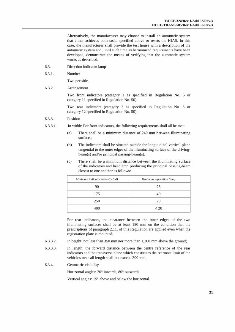
6.3.3.1. In width: For front indicators, the following requirements shall all be met:
(a) There shall be a minimum distance of 240 mm between illuminating
surfaces;
(b) The indicators shall be situated outside the longitudinal vertical plane
tangential to the outer edges of the illuminating surface of the driving-
beam(s) and/or principal passing-beam(s);
(c) There shall be a minimum distance between the illuminating surface
of the indicators and headlamp producing the principal passing-beam
closest to one another as follows:
Minimum indicator intensity (cd) Minimum separation (mm)
90 75
175 40
250 20
400 ≤ 20
For rear indicators, the clearance between the inner edges of the two
illuminating surfaces shall be at least 180 mm on the condition that the
prescriptions of paragraph 2.11. of this Regulation are applied even when the
registration plate is mounted;
6.3.3.2. In height: not less than 350 mm nor more than 1,200 mm above the ground;
6.3.3.3. In length: the forward distance between the centre reference of the rear
indicators and the transverse plane which constitutes the rearmost limit of the
vehicle's over-all length shall not exceed 300 mm.
6.3.4. Geometric visibility
Horizontal angles: 20° inwards, 80° outwards.
Vertical angles: 15° above and below the horizontal.
E/ECE/324/Rev.1/Add.52/Rev.3
E/ECE/TRANS/505/Rev.1/Add.52/Rev.3
22
The vertical angle below the horizontal may be reduced to 5°, however, if the
height of the lamps is less than 750 mm.
6.3.5. Orientation
The front direction indicators may move in line with the steering angle.
6.3.6. Electrical connections
Direction indicator lamps shall switch on independently of the other lamps.
All direction indicator lamps on one side of a vehicle shall be switched on
and off by means of one control.
6.3.7. May not be "reciprocally incorporated" with any other lamp, except amber
front position lamp.
6.3.8. "Operating" tell-tale
Mandatory. This may be optical or auditory or both. If it is optical it shall be
(a) flashing green lamp(s), which, in the event of defective operation of any
of the direction indicators, is extinguished, remains alight without flashing, or
shows a marked change of frequency.
6.3.9. Other requirements
The characteristics indicated below shall be measured with no other load on
the electrical system than that required for the operation of the engine and the
lighting devices. For all vehicles:
6.3.9.1. The light flashing frequency shall be 90 ± 30 times per minute;
6.3.9.2. The flashing of the direction indicators on the same side of the vehicle may
occur synchronously or alternately;
6.3.9.3. Operation of the light-signal control shall be followed within not more than
one second by the appearance of the light and within not more than one-and-
one half seconds by the first extinction of the light.
6.3.9.4. In the event of failure, other than a short circuit, of one direction indicator
lamp, the other(s) direction indicator lamp(s) indicating the same direction
must continue to flash or remain alight, but the frequency in this condition
may be different from that prescribed.
6.4. Stop lamp
6.4.1. Number
One or two.
6.4.2. Arrangement
No special requirement.
6.4.3. Position
6.4.3.1. In height: not less than 250 mm nor more than 1,500 mm above the ground;
6.4.3.2. In length: at the rear of the vehicle.
6.4.4. Geometric visibility
Horizontal angle: 45° to left and to right for a single lamp;
45° outwards and 10° inwards for each pair of lamps.
Vertical angle: 15° above and below the horizontal.
E/ECE/324/Rev.1/Add.52/Rev.3
E/ECE/TRANS/505/Rev.1/Add.52/Rev.3
23
The vertical angle below the horizontal may be reduced to 5°, however, if the
height of the lamp is less than 750 mm.
6.4.5. Orientation
Towards the rear of the vehicle.
6.4.6. Electrical connections
Shall light up at any service brake application.
6.4.7. "Tell-tale"
Tell-tale optional; where fitted, this tell-tale shall be a tell-tale consisting of a
non-flashing warning light which comes on in the event of the
malfunctioning of the stop lamps.
6.4.8. Other requirements
None.
6.5. Rear-registration-plate illuminating device
6.5.1. Number
One, approved as a category 2 device according to Regulation No. 50. The
device may consist of several optical components designed to illuminate the
space reserved for the registration plate.
6.5.2. Arrangement
Such that the device illuminates
the space reserved for the
registration plate.
6.5.3. Position
6.5.3.1. In width:
6.5.3.2. In height:
6.5.3.3. In length:
6.5.4. Geometric visibility
6.5.5. Orientation
6.5.6. Tell-tale
Optional: Its function shall be performed by the tell-tale prescribed for the
position lamp.
6.5.7. Other requirements
When the rear registration plate lamp is combined with the rear position
lamp, reciprocally incorporated in the stop lamp or in the rear fog lamp, the
photometric characteristics of the rear registration plate lamp may be
modified during the illumination of the stop lamp or the rear fog lamp.
6.6. Front position lamp
6.6.1. Number
One or two if coloured white
or
Two (one per side) if coloured amber
6.6.2. Arrangement
No special requirement.
E/ECE/324/Rev.1/Add.52/Rev.3
E/ECE/TRANS/505/Rev.1/Add.52/Rev.3
24
6.6.3. Position
6.6.3.1. Width:
An independent front position lamp may be fitted above or below, or to one
side of another front lamp: if these lamps are one above the other, the
reference centre of the front position lamp must be located within the median
longitudinal plane of the vehicle; if these lamps are side by side, their
reference centres must be symmetrical in relation to the median longitudinal
plane of the vehicle;
A front position lamp, that is reciprocally incorporated with another front
lamp, must be installed in such a way that its reference centre is situated in
the median longitudinal plane of the vehicle. However, when the vehicle is
also fitted with another front lamp alongside the front position lamp, their
reference centres must be symmetrical in relation to the median longitudinal
plane of the vehicle.
Two front position lamps, one or both of them reciprocally incorporated with
another front lamp, must be installed in such a way that their reference
centres are symmetrical in relation to the median longitudinal plane of the
vehicle.
6.6.3.2. In height: not less than 350 mm nor more than 1,200 mm above the ground.
6.6.3.3. In length: at the front of the vehicle.
6.6.4. Geometric visibility
Horizontal angle: 80 degrees to the left and to the right for a single
lamp: the horizontal angle may be 80 degrees
outwards and 20 degrees inwards for each pair of
lamps.
Vertical angle: 15 degrees above and below the horizontal.
The vertical angle below the horizontal may be reduced to 5 degrees,
however, if the height of the lamp is less than 750 mm.
6.6.5. Orientation
Forwards. The lamp(s) may move in line with the steering angle.
6.6.6. "Circuit-closed" tell-tale
Mandatory. Non-flashing green signal lamp. This tell-tale shall not be
required if the instrument illumination lighting can be switched on or off only
simultaneously with the position lamp(s).
6.6.7. Other requirements
When the front position lamp is reciprocally incorporated in the front
direction indicator lamp, the electrical connection shall be such that the
position lamp on the same side as the direction indicator lamp is switched off
when the direction indicator lamp is flashing.
6.7. Rear position lamp
6.7.1. Number
One or two.
E/ECE/324/Rev.1/Add.52/Rev.3
E/ECE/TRANS/505/Rev.1/Add.52/Rev.3
25
6.7.2. Arrangement
No special requirements.
6.7.3. Position
6.7.3.1. in height: not less than 250 mm nor more than 1,500 mm above the ground;
6.7.3.2. in length: at the rear of the vehicle.
6.7.4. Geometric visibility
Horizontal angle: 80° to left and to right for a single lamp:
the horizontal angle may be 80° outwards and 45°
inwards for each pair of lamps.
Vertical angle: 15° above and below the horizontal.
The vertical angle below the horizontal may be reduced to 5°, however, if the
height of the lamp is less than 750 mm.
6.7.5. Orientation
Rearwards.
6.7.6. "Circuit-closed" tell-tale
Optional: Its function shall be performed by the device prescribed for the
front position lamp.
6.7.7. Other requirements
If a rear position lamp is reciprocally incorporated with a direction indicator,
the electrical connection of the rear position lamp on the relevant side of the
vehicle or the reciprocally incorporated part of it may be such that it is
switched OFF during the entire period (both ON and OFF cycle) of activation
of the direction indicator lamp.
6.8. Rear retro-reflector, non-triangular
6.8.1. Number
One or two.
6.8.2. Arrangement
No special requirement.
6.8.3. Position
In height: not less than 250 mm nor more than 900 mm above the ground;
6.8.4. Geometric visibility
Horizontal angle: 30° to left and to right for a single reflector;
30° outwards and 10° inwards for each pair of
reflectors;
Vertical angle: 15° above and below the horizontal.
The vertical angle below the horizontal may be reduced to 5°, however, if the
height of the lamp is less than 750 mm.
6.8.5. Orientation
Rearwards.
E/ECE/324/Rev.1/Add.52/Rev.3
E/ECE/TRANS/505/Rev.1/Add.52/Rev.3
26
6.9. Vehicle-hazard warning signal
6.9.1. The signal shall be given by simultaneous operation of the direction indicator
lamps in accordance with the requirements of paragraph 6.3. above.
6.9.2. Electrical connections
The signal shall be given by means of a separate control enabling all the
direction indicators to be supplied with current simultaneously.
6.9.3. "Circuit-closed" tell-tale
Mandatory. Flashing red signal lamp or, in the case of separate tell-tales, the
simultaneous operation of the tell-tale prescribed in paragraph 6.3.10.
6.9.4. Other requirements
Light flashing 90 ± 30 times per minute.
Operation of the lamp-signal control shall be followed within not more than
one second by the appearance of the light and within not more than one-and-
one-half seconds by the first extinction of the light.
6.10. Front fog lamp
6.10.1. Number
One or two.
6.10.2. Arrangement
No special requirement.
6.10.3. Position
6.10.3.1. In width: for a single lamp the centre of reference shall be in the median
longitudinal plane of the vehicle; or the edge of the illuminating surface
which is nearest to that plane shall be not more than 250 mm away from it;
6.10.3.2. In height: not less than 250 mm above the ground. No point on the
illuminating surface shall be higher than the highest point on the illuminating
surface of the passing-beam headlamp.
6.10.3.3. In length: at the front of the vehicle. This requirement shall be deemed to be
satisfied if the light emitted does not cause discomfort to the driver either
directly, or indirectly through the rear-view mirrors and/or other reflecting
surfaces of the vehicle.
6.10.4. Geometric visibility
Defined by angles α and β as specified in paragraph 2.11.:
α = 5° upwards and downwards;
β = 45° to left and to right for a single lamp, except for an off-
centre light, in which case the inward angle β = 10°;
β = 45° outwards and 10° inwards for each pair of lamps
6.10.5. Orientation
Forwards. The lamp(s) may move in line with the steering angle.
6.10.6. May not be combined with any other front lamp.
E/ECE/324/Rev.1/Add.52/Rev.3
E/ECE/TRANS/505/Rev.1/Add.52/Rev.3
27
6.10.7. "Circuit-closed" tell-tale
Optional; non-flashing green signal.
6.10.8. Other requirements
None.
6.10.9. Electrical connections
It shall be possible to switch the fog lamp(s) on or off independently of the
driving-beam headlamp(s) and/or passing-beam headlamp(s).
6.11. Rear fog lamp
6.11.1. Number
One or two.
6.11.2. Arrangement
No special requirement.
6.11.3. Position
6.11.3.1. In height: not less than 250 mm nor more than 900 mm above the ground;
6.11.3.2. In length at the rear of the vehicle.
6.11.3.3. The distance between the illuminating surface of the rear fog lamp and that of
the stop lamp shall not be less than 100 mm.
6.11.4. Geometric visibility
Defined by angles α and β as specified in paragraph 2.11. of this Regulation:
α = 5° upwards and downwards;
β = 25° to left and to right for a single lamp;
25° outwards and 10° inwards for each pair of lamps.
6.11.5. Orientation
Rearwards.
6.11.6. Electrical connections
They shall be such that the rear fog lamp can light up only when one or more
of the following lamps are switched on: driving-beam headlamp, passing-
beam headlamp, front fog lamp.
If there is a front fog lamp, it shall be possible to switch off the rear fog lamp
independently of the front fog lamp.
The rear fog lamp(s) may continue to operate until the position lamps are
switched off and they shall remain off until deliberately switched on again.
6.11.7. "Circuit-closed" tell-tale
Mandatory. Non-flashing amber signal lamp.
6.11.8. Other requirements
None.
E/ECE/324/Rev.1/Add.52/Rev.3
E/ECE/TRANS/505/Rev.1/Add.52/Rev.3
28
6.12. Side retro-reflector, non-triangular
6.12.1. Number per side
One or two.
6.12.2. Arrangement
No special requirement.
6.12.3. Position
6.12.3.1. On the side of the vehicle.
6.12.3.2. In height: not less than 300 mm nor more than 900 mm above the ground;
6.12.3.3. In length: should be placed in such a position that under normal conditions it
may not be masked by the driver's or passenger's clothes.
6.12.4. Geometric visibility
Horizontal angles β = 30° to the front and to the rear.
Vertical angles α = 15° above and below the horizontal.
The vertical angle below the horizontal may be reduced to 5°, however, if the
height of the retro-reflector is less than 750 mm.
6.12.5. Orientation
The reference axis of the retro-reflectors must be perpendicular to the
vehicle’s median longitudinal plane and directed outwards. The front side
retro-reflectors may move with the steering angle.
6.13. Daytime running lamp
6.13.1. Presence
Optional for motorcycles.
6.13.2. Number
One or two of approved type according to Regulation No. 87.
6.13.3. Arrangement
No special requirement.
6.13.4. Position
6.13.4.1. In width:
6.13.4.1.1. An independent daytime running lamp may be installed above, below or to
one side of another front lamp: If these lamps are one above the other, the
reference centre of the daytime running lamp shall be located within the
medium longitudinal plane of the vehicle; if these lamps are side by side, the
edge of the illuminating surface shall not be more than 250 mm from the
median longitudinal plane of the vehicle.
6.13.4.1.2. A daytime running lamp, that is reciprocally incorporated with another front
lamp (driving-beam headlamp or front position lamp), shall be fitted in such
a way that the edge of the illuminated surface lies not more than 250 mm
from the median longitudinal plane of the vehicle.
E/ECE/324/Rev.1/Add.52/Rev.3
E/ECE/TRANS/505/Rev.1/Add.52/Rev.3
29
6.13.4.1.3. Two daytime running lamps, of which either one or both are reciprocally
incorporated with another front lamp, shall be installed in such a way that
their reference centres are symmetrical in relation to the median longitudinal
plane of the vehicle.
6.13.4.1.4. In the case of two daytime running lamps, the distance separating the
illuminating surfaces shall not exceed 420 mm.
6.13.4.1.5. The maximum separation distance is not applicable when the daytime
running lamps:
(a) Are grouped, combined or reciprocally incorporated with another
headlamp, or
(b) Are within the projection of the frontal silhouette of the motorcycle on
an orthogonal plane perpendicular to the longitudinal median plane of
the vehicle.
6.13.4.2. In height:
Above the ground not less than 250 mm and not more than 1,500 mm.
6.13.4.3. In length:
At the front of the vehicle.
6.13.5. Geometric visibility
Horizontal: Outwards 20° and inwards 10°.
Vertical: Upwards 10° and downwards 10°.
6.13.6. Orientation
Towards the front. The lamp(s) may move in line with the steering angle.
6.13.7. Electrical connections
6.13.7.1. The daytime running lamp shall switch OFF automatically when the
headlamps are switched ON, except when the latter are used to give
intermittent luminous warnings at short intervals.
The rear position lamp shall be switched ON when the daytime running
lamp(s) is/are switched ON. The front position lamp(s) and the rear-
registration-plate illuminating device may be switched ON individually or
together, when the daytime running lamp(s) is/are switched ON.
6.13.7.2. If the distance between the front direction indicator lamp and the daytime
running lamp is equal or less than 40 mm, the electrical connections of the
daytime running lamp on the relevant side of the vehicle may be such that
either:
(a) It is switched OFF; or
(b) Its luminous intensity is reduced during the entire period (both ON
and OFF cycle) of activation of a front direction indicator lamp.
6.13.7.3. If a direction indicator lamp is reciprocally incorporated with a daytime
running lamp, the electrical connections of the daytime running lamp on the
relevant side of the vehicle shall be such that the daytime running lamp is
switched OFF during the entire period (both ON and OFF cycle) of activation
of the direction indicator lamp.
E/ECE/324/Rev.1/Add.52/Rev.3
E/ECE/TRANS/505/Rev.1/Add.52/Rev.3
30
6.13.8. Tell-tale
Closed-circuit green tell-tale, optional.
6.13.9. Other requirements
The DRL symbol in ISO 2575:2004 - Road vehicles. Symbols for controls,
indicators and tell-tales, may be used to inform the driver that the daytime
running lamp is on.
7. Modifications of the vehicle type or of the installation of its lighting and light-signalling devices
7.1. Every modification of the vehicle type, or of the installation of its lighting or
light-signalling devices, or of the list referred to in paragraph 3.2.2. above,
shall be notified to the Type Approval Authority which approved that vehicle
type. The Type Approval Authority may then either;
7.1.1. Consider that the modification made are unlikely to have appreciable adverse
effects and that in any case the vehicle still complies with the requirements;
or
7.1.2. Require a further test report from the Technical Service responsible for
conducting tests.
7.2. Confirmation or refusal of approval, specifying the alternatives, shall be
communicated by the procedure specified in paragraph 4.3. above to the
Parties to the Agreement which apply this Regulation.
7.3. The Type Approval Authority issuing the extension of approval shall assign a
series number for such an extension and inform thereof the other Parties to
the 1958 Agreement applying this Regulation by means of a communication
form conforming to the model in Annex 1 to this Regulation.
8. Conformity of production
The conformity of production procedures shall comply with those set out in
the Agreement, Appendix 2 (E/ECE/324-E/ECE/TRANS/505/Rev.2), with
the following requirements:
8.1. Motorcycles approved under this Regulation shall be so manufactured as to
conform to the type approved, by meeting the requirements set out in
paragraphs 5. and 6. above.
8.2. The minimum requirements for conformity of production control procedures
set forth in Annex 5 to this Regulation shall be complied with.
8.3. The Type Approval Authority which has granted type approval may at any
time verify the conformity control methods applied in each production
facility. The normal frequency of these verifications shall be once a year.
E/ECE/324/Rev.1/Add.52/Rev.3
E/ECE/TRANS/505/Rev.1/Add.52/Rev.3
31
9. Penalties for non-conformity of production
9.1. The approval granted in respect of a vehicle type pursuant to this Regulation
may be withdrawn if the requirement laid down in paragraph 8.1. above is
not met or if the vehicle has failed to pass the checks prescribed in
paragraph 8. above.
9.2. If a Party to the Agreement which applies this Regulation withdraws an
approval it has previously granted, it shall forthwith so notify the other
Contracting Parties to the Agreement which apply this Regulation by means
of a communication form conforming to the model in Annex 1 to this
Regulation.
10. Production definitively discontinued
If the holder of an approval completely ceases to manufacture a vehicle type
approved in accordance with this Regulation, he shall so inform the Type
Approval Authority which granted the approval. Upon receiving the relevant
communication that Authority shall inform thereof the other Parties to the
Agreement applying this Regulation, by means of a communication form
conforming to the model in Annex 1 to this Regulation.
11. Transitional provisions
11.1. As from the official date of entry into force of Supplement 10 to the 01 series
of amendments, no Contracting Party applying this Regulation shall refuse to
grant approvals under this Regulation as amended by Supplement 10 to the
01 series of amendments.
11.2. As from 60 months after the date of entry into force mentioned in
paragraph 11.1. above, Contracting Parties applying this Regulation shall
grant approvals only if the vehicle type with regard to the number and mode
of installation of the lighting and light-signalling devices corresponds to the
requirements of the Supplement 10 to the 01 series of amendments to this
Regulation.
11.3. Existing approvals granted under this Regulation before the date mentioned
in paragraph 11.2. above shall remain valid. In the case of vehicles first
registered more than 84 months after the date of entry into force mentioned in
paragraph 11.1. above Contracting Parties applying this Regulation may
refuse the vehicle type with regard to the number and mode of installation of
the lighting and light-signalling devices which do not meet the requirements
of the Supplement 10 to the 01 series of amendments to this Regulation.
12. Names and addresses of Technical Services responsible for conducting approval tests, and of Type Approval Authorities
The Parties to the 1958 Agreement which apply this Regulation shall
communicate to the United Nations secretariat the names and addresses of the
Technical Services responsible for conducting approval tests and of the Type
Approval Authorities which grant approval and to which forms certifying
approval, extension or refusal or withdrawal of approval, issued, in other
countries, are to be sent.
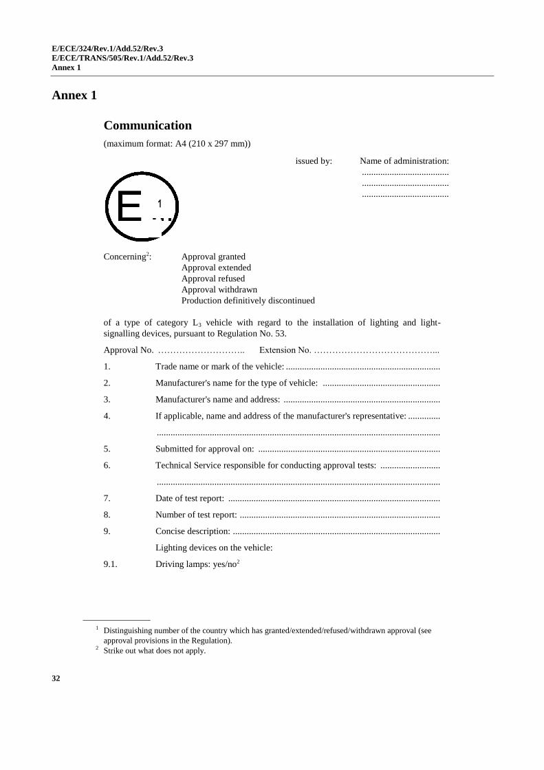
E/ECE/324/Rev.1/Add.52/Rev.3
E/ECE/TRANS/505/Rev.1/Add.52/Rev.3
Annex 1
32
Annex 1
Communication
(maximum format: A4 (210 x 297 mm))
1
Concerning2: Approval granted
Approval extended
Approval refused
Approval withdrawn
Production definitively discontinued
of a type of category L3 vehicle with regard to the installation of lighting and light-
signalling devices, pursuant to Regulation No. 53.
Approval No. ……………………….. Extension No. …………………………………...
1. Trade name or mark of the vehicle: ...................................................................
2. Manufacturer's name for the type of vehicle: ...................................................
3. Manufacturer's name and address: ....................................................................
4. If applicable, name and address of the manufacturer's representative: ..............
...........................................................................................................................
5. Submitted for approval on: ...............................................................................
6. Technical Service responsible for conducting approval tests: ..........................
...........................................................................................................................
7. Date of test report: ............................................................................................
8. Number of test report: .......................................................................................
9. Concise description: ..........................................................................................
Lighting devices on the vehicle:
9.1. Driving lamps: yes/no2
1 Distinguishing number of the country which has granted/extended/refused/withdrawn approval (see
approval provisions in the Regulation).
2 Strike out what does not apply.
issued by: Name of administration:
......................................
......................................
......................................
1
E/ECE/324/Rev.1/Add.52/Rev.3
E/ECE/TRANS/505/Rev.1/Add.52/Rev.3
Annex 1
33
9.2. Passing lamps: yes/no2
9.3. Front fog lamps: yes/no2
9.4. -
9.5. Direction indicators: yes/no2
9.6. -
9.7. Repeating side direction indicators: yes/no2
9.8. Hazard warning signal: yes/no2
9.9. Stop lamps: yes/no2
9.10. Rear-registration-plate illuminating device: yes/no2
9.11. Front position (side) lamps: yes/no2
9.12. Rear position (side) lamps: yes/no2
9.13. Rear fog lamps: yes/no2
9.14. -
9.15. -
9.16. Rear retro-reflectors, non-triangular: yes/no2
9.17. -
9.18. -
9.19. Side retro-reflectors, non-triangular: yes/no2
9.20. Equivalent lamps: yes/no2
10. Any comments: .................................................................................................
11. Masses as declared by the manufacturer3
11.1. Mass in running order:
Total mass: .................................................................................................... kg
Mass on the front wheel: ............................................................................... kg
Mass on the rear wheel: ................................................................................ kg
11.2. Gross vehicle mass:
Total mass: ..................................................................................................... kg
Mass on the front wheel: ............................................................................... kg
Mass on the rear wheel: ................................................................................ kg
12. Position of the approval mark: ..........................................................................
13. Reason(s) for extension (if applicable):
3 These sections only need to be completed if the test according to paragraph 6.2.5.4. of this Regulation
is performed.
E/ECE/324/Rev.1/Add.52/Rev.3
E/ECE/TRANS/505/Rev.1/Add.52/Rev.3
Annex 1
34
14. Approval granted/refused/extended/withdrawn:2
15. Place: ................................................................................................................
16. Date: .................................................................................................................
17. Signature: ..........................................................................................................
18. The list of documents deposited with the Type Approval Authority which has
granted the approval is annexed to this communication and may be obtained
upon request.
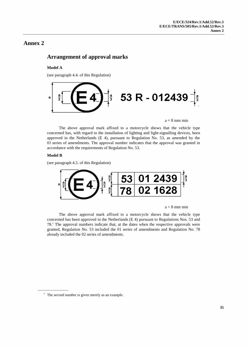
E/ECE/324/Rev.1/Add.52/Rev.3
E/ECE/TRANS/505/Rev.1/Add.52/Rev.3
Annex 2
35
Annex 2
Arrangement of approval marks
Model A
(see paragraph 4.4. of this Regulation)
a = 8 mm min
The above approval mark affixed to a motorcycle shows that the vehicle type
concerned has, with regard to the installation of lighting and light-signalling devices, been
approved in the Netherlands (E 4), pursuant to Regulation No. 53, as amended by the
01 series of amendments. The approval number indicates that the approval was granted in
accordance with the requirements of Regulation No. 53.
Model B
(see paragraph 4.5. of this Regulation)
a = 8 mm min
The above approval mark affixed to a motorcycle shows that the vehicle type
concerned has been approved in the Netherlands (E 4) pursuant to Regulations Nos. 53 and
78.1 The approval numbers indicate that, at the dates when the respective approvals were
granted, Regulation No. 53 included the 01 series of amendments and Regulation No. 78
already included the 02 series of amendments.
1 The second number is given merely as an example.
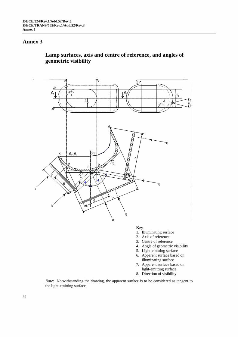
E/ECE/324/Rev.1/Add.52/Rev.3
E/ECE/TRANS/505/Rev.1/Add.52/Rev.3
Annex 3
36
1
35
44
8
8
8
8
8
8
3
1A A
5
2
1
4
4
3
2
a b
6
7
67
A-Ac
d
Annex 3
Lamp surfaces, axis and centre of reference, and angles of geometric visibility
Key
1. Illuminating surface
2. Axis of reference
3. Centre of reference
4. Angle of geometric visibility
5. Light-emitting surface
6. Apparent surface based on
illuminating surface
7. Apparent surface based on
light-emitting surface
8. Direction of visibility
Note: Notwithstanding the drawing, the apparent surface is to be considered as tangent to
the light-emitting surface.
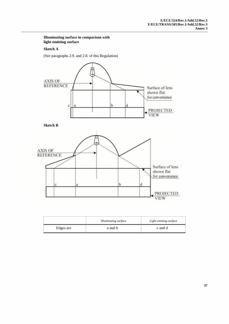
E/ECE/324/Rev.1/Add.52/Rev.3
E/ECE/TRANS/505/Rev.1/Add.52/Rev.3
Annex 3
37
Illuminating surface in comparison with
light-emitting surface
Sketch A
(See paragraphs 2.9. and 2.8. of this Regulation)
Sketch B
Illuminating surface Light-emitting surface
Edges are a and b c and d
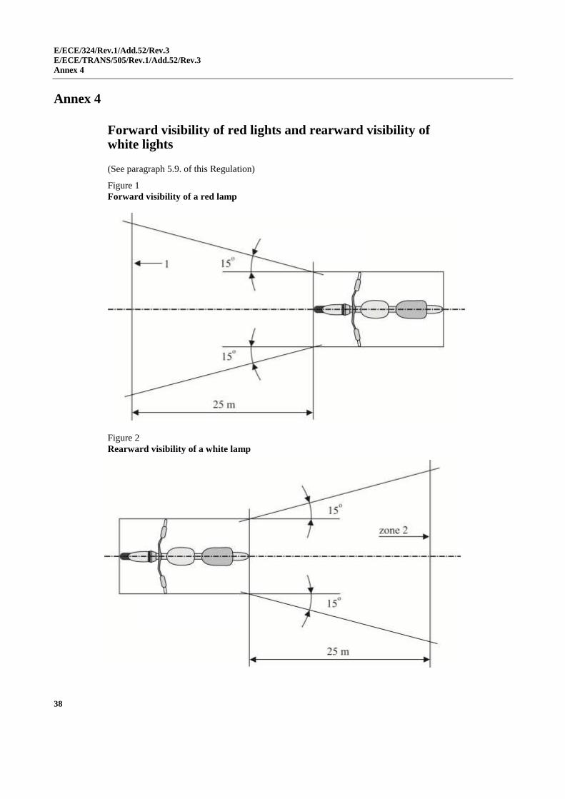
E/ECE/324/Rev.1/Add.52/Rev.3
E/ECE/TRANS/505/Rev.1/Add.52/Rev.3
Annex 4
38
Annex 4
Forward visibility of red lights and rearward visibility of white lights
(See paragraph 5.9. of this Regulation)
Figure 1
Forward visibility of a red lamp
Figure 2
Rearward visibility of a white lamp
E/ECE/324/Rev.1/Add.52/Rev.3
E/ECE/TRANS/505/Rev.1/Add.52/Rev.3
Annex 5
39
Annex 5
Control of conformity of production
1. Tests
1.1. Position of lamps
The position of the lamps as specified in paragraph 6. of this Regulation shall
be checked in accordance with the general requirements set out in paragraph
5. of this Regulation. The values measured for the distances shall be such that
the individual specifications applicable to each lamp are fulfilled.
1.2. Visibility of lamps
1.2.1. The angles of geometric visibility shall be checked in accordance with
paragraph 2.11. of this Regulation. The values measured for the angles shall
be such that the individual specifications applicable to each lamp are fulfilled
except that the limits of the angles may have an allowance corresponding to
the ±3° variation permitted in paragraph 5.3. of this Regulation for the
mounting of the light-signalling devices.
1.2.2. The visibility of red light towards the front and of white light towards the rear
shall be checked in accordance with paragraph 5.9. of this Regulation.
1.3. Alignment of passing-beam headlamps towards the front
1.3.1. Initial downward inclination
(The initial downward inclination of the cut-off of the passing-beam shall be
checked against the requirements of paragraph 6.2.5. of this Regulation).
1.4. Electrical connections and tell-tales
The electrical connections shall be checked by switching on every lamp
supplied by the electrical system of the motorcycle.
The lamps and tell-tales shall function in accordance with the provisions set
out in paragraphs 5.10. to 5.12. of this Regulation and with the individual
specifications, applicable to each lamp.
1.5. Light intensities
1.5.1. Driving-beam headlamps
The aggregate maximum intensity of the driving-beam headlamp(s) shall be
such that the requirement in paragraph 6.1.9. of this Regulation is fulfilled.
1.6. The presence, number, colour, arrangement and, where applicable, the
category of lamps shall be checked by visual inspection of the lamps and
their markings. These shall be such that the requirements set out in
paragraph 5.13. of this Regulation and the individual specifications
applicable to each lamp are fulfilled.
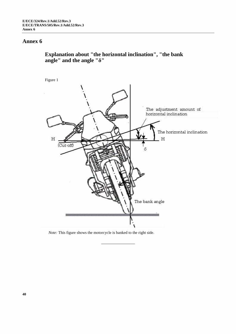
E/ECE/324/Rev.1/Add.52/Rev.3
E/ECE/TRANS/505/Rev.1/Add.52/Rev.3
Annex 6
40
Annex 6
Explanation about "the horizontal inclination", "the bank angle" and the angle "δ"
Figure 1
Note: This figure shows the motorcycle is banked to the right side.