Embed Size (px)
Citation preview
AIMS POWER AIMS MPPT+ SERIES
SOLAR CHARGE CONTROLLERSCC40MPPT / SCC80MPPT
Installation and Operation Manual
MANUAL VER.1, 1111

CONTENTS
Chapter 6 Trouble Shooting.......................................................................................................6-1

IntroductionThe AIMS MPPT+ is a highly reliable solar battery charger and its most critical feature is to maximize the harvest energy from the PV array into the battery by using advanced technology of Maximum Power Point Tracking (MPPT). The battery types that the AIMS MPPT+ will charge include Flooded Lead Acid (FLA), GEL , AGM chemistries in the range of 12Vdc, 24Vdc, 36Vdc and 48Vdc nominal. The high efficiency of charging ability can be accomplished through a 2 or 3 or 4-stage charger depending on the battery type. It was designed with built-in protection circuitry to ensure batteries will not be over or under charged.
The wide range of the input array voltage and output battery voltage are well applied to the solar system to allow system planner to produce the most of the solar energy. The input PV array of the SCC40MPPT and SCC80MPPT may be wired in the range of 16~192Vdc nominal. The output battery voltage is accepted from 12 to 48Vdc nominal. After wiring up and operation, the built-in intelligent data logging system can track the state of charge (SOC) and the harvest power produced over time.
AIMS MPPT+ may not only be used in solar systems but also in wind or hybrid systems. With respect to these systems, the 2 auxiliary relays can be programmed by constants setting. The functions and programming of the relays help to control the dump loads. Multiple AIMS MPPT+ with cables (up to 16 units) can be connected in larger power systems. The controller with optional rectifier and braking unit for wind system is required to control and stop the control from overload condition caused by excessively high wind speeds..Please carefully read through this manual and all the installation instructions and wiring before beginning installation of your AIMS MPPT+. The protection and installation equipment should comply with local codes. The rated fuses, breakers and external lightning protection should be installed along with AIMS MPPT+.
Features Integrates Maximum Power Point Tracking (MPPT), battery charge management, state of charge
information. Continuous output Power Rating without de-rating at up to 50 ambient temperature. ℃ Built-in Battery Energy Monitor tracks power production and consumption in order to calculate the energy remaining in the battery bank. State of charge (SOC) is displayed in percentage of full capacity, Amp-hours, Watt-hours, and 90 days of energy-harvest history and is
stored in the solar charger. Supports Flooded Lead Acid (FLA), GEL, Absorbed Glass Mat (AGM) batteries; 2/3/4-stage
charging with adjustable set points for all parameters. Wire the PV modules in series up to 192VDC normal (240VDC Max) for SCC40MPPT Series,
SCC80MPPT Series. Easy stacking of up to 16 units in parallel for high currents. Precision charging of 12V/ 24V/36V/48V batteries with easy set-up. Use of battery voltage sense
(BVS) wires is required. Built-in temperature compensation function for safe and complete charging.
Specification Model No. SCC40MPPT MPPT SCC80MPPT MPPT
Maximum output current(Continuous at up 50℃ ambient temperature)
40 Amps 80 Amps
Battery Voltages 12, 24, 36, 48 VDC NormalMax PV Input Current 30 Amps 70 Amps
Input Voltage Range16~192VDC Operating
240VDC Maximum Open Circuit Voltage
Max PV Array Power2600 Watts
(Maximum when equalizing a 48V battery to 64V at 40 Amps)
5200 Watts (Maximum when equalizing a
48V battery to 64V at 80 Amps)
Charge Regulation Modes Bulk, Absorption, Float, Auto/ Manual EqualizationBattery Temperature Compensation 5.0 mV per , per 2 volt cell℃
DC to DC Conversion Capability
12V Battery: 16~192VDC24V Battery: 32~192VDC
36V Battery: 48~192VDC
48V Battery: 64~192VDC
Display StatusBuilt-in 2-line, 20-character LCD with backlight LCD status screen displays input voltage and current, output voltage and current, charge-mode, Battery SOC
Data Logging Logs energy harvested for 90 days, LCD displays WH, KWH, AH
Energy Monitor LCD shows SOC, AH, WH, and present charge or discharge current. A 50mV/ 500Amp shunt is required
Auxiliary Relays Two independent relays A (SPST) for control of external devices. Contact rating is 3 Amps, 50VDC
Operation Temperature Full Power Output to +50 ambient℃Standby Power < 2 Watts < 4 WattsDimension 267.6 x 196 x 147 mm 414.8 x 225 x 147 mmWeight 4.3 Kgs 7.1 Kgs
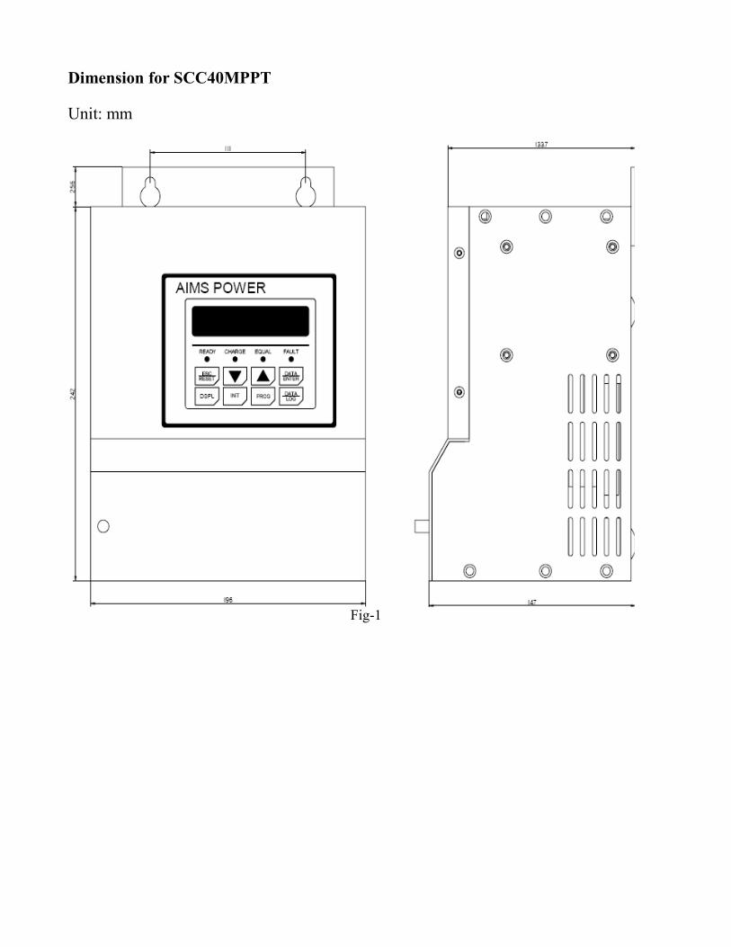
Dimension for SCC40MPPT
Unit: mm
Fig-1
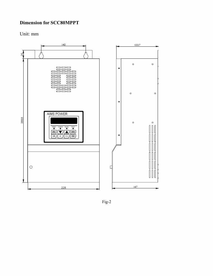
Dimension for SCC80MPPT
Unit: mm
Fig-2
Chapter 1 Installation
1.1 Load Requirement The AIMS MPPT+ series plays a major role in planning your PV system. The first step in planning an efficient PV system is to calculate the load requirement. In order to calculate the anticipated load requirement, it is important to determine average and peak load consumption. The possible load growth should also be taken into consideration when planning the load requirement because loads hardly remain static and they grow more frequently than they reduce.
1.2 Battery Voltage SystemAfter the estimate of the power requirement, the required power from the battery will be the next consideration in planning the system. According to the basic rule of the electricity, “Current is the power divided by voltage”, when the power amount increases, it is suggested to raise the battery voltage so the current amount will decrease. The principle is based on the larger amount of current that exists, the more expensive the circuit protection is. In an example of the 96 watt load, it draws 4 amps at 24V battery system but it draws only 2 amps at 48V system. Cable size thus also decreased as current is decreased. It is another reason to up the Voltage in larger systems.
1.3 PV Array VoltageAs the AIMS MPPT+ is a smart DC to DC converter design, the specification of a PV array is much like sizing a grid tie inverter. Installers choose the max. and min. Vmp and Voc of each string and how many strings are needed.
1.4 Maximum VocThe maximum operating voltage of the SCC40MPPT and SCC80MPPT is 240Vdc. The protection will be active to shut down the unit when the operating voltage is higher. PV array manufacturers have the published data sheet with rated voltage and current as well as the current and temperature coefficients. The rated Voc is measured in the temperature of 25℃ so when calculated at lower temperature such as 0℃, 25% increase of the rated Voc is expected. At different temperatures dependent on location, the maximum Voc of the module should be determined by the Voc voltage temperature coefficient and after that, a series string voltage may be determined as well.
1.5 Shunt (BCS)The Shunt is an optional component and it is required for the AIMS MPPT+ to achieve the optimal operation levels. It also functions as a hub for connecting measurement sensors. The main purpose of the shunt is to allow the AIMS MPPT+ to measure current drawing into and out of the battery bank. DC load centers are where the AIMS MPPT+ Shunt is recommended to be placed. Installing it in an electrical enclosure is also acceptable. Locating the Shunt is essential for safety. Please note that the capacity of the Shunt is 50mV, 500Amp. See page 2-3 for wiring connection terminal.
1.6 Battery Temperature Sensor (BTS-3)The battery temperature sensor BTS-3 is used to compensate charging by adjusting charging voltage up or down according to the temperature detected by the sensor.See page 2-3 for wiring connection terminal. The AIMS MPPT+ requires BTS-3 to be connected for all charging features to be available. AIMS MPPT+ is able to operate without the sensor, but Absorption Trigger set points will be lower and equalization stage will be disabled. BTS-3 can be mounted on the battery posts.
1.7 Battery Voltage Sensing (BVS)Connect the red wire to a battery positive bus and the black wire to a battery negative bus within the DC load center. See page 2-3 for wiring connection terminal. Two sense wires may be connected to compensate possible battery cable loss during charging. Be sure to observe correct polarity when installing voltage sense wires or damage will result.
1.8 Wiring DiagramBefore starting to initiate the AIMS MPPT+, keep all breakers in the OFF position. When you are ready to start the AIMS MPPT+, turn on ONLY the Battery breaker. Do NOT turn on the PV breaker until the instruction on LCD shows during AIMS MPPT+ initialization. The internal electric circuit of the AIMS MPPT+ can only be powered by the batteries.The installation environment of AIMS MPPT+ should be in an area of good ventilation. Never locate the AIMS MPPT+ in a poorly ventilated battery area because batteries emit explosive gases. Do not locate the AIMS MPPT+ within 1 meter of the batteries to ensure a safe distance.See next page for the wiring diagram of SCC40MPPT as an example.
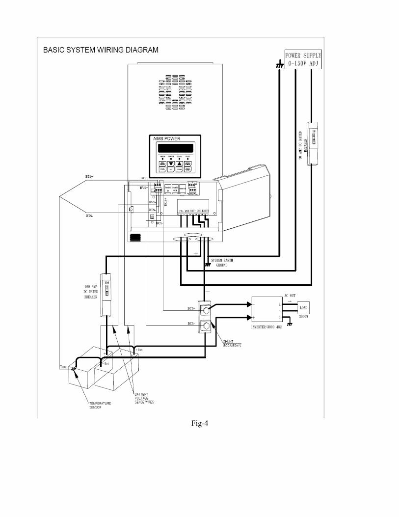
Fig-4
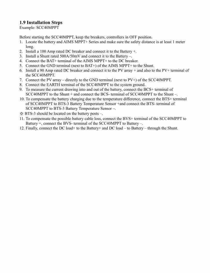
1.9 Installation StepsExample: SCC40MPPT
Before starting the SCC40MPPT, keep the breakers, controllers in OFF position. 1. Locate the battery and AIMS MPPT+ Series and make sure the safety distance is at least 1 meter
long. 2. Install a 100 Amp rated DC breaker and connect it to the Battery +.3. Install a Shunt rated 500A/50mV and connect it to the Battery –. 4. Connect the BAT+ terminal of the AIMS MPPT+ to the DC breaker. 5. Connect the GND terminal (next to BAT+) of the AIMS MPPT+ to the Shunt.6. Install a 90 Amp rated DC breaker and connect it to the PV array + and also to the PV+ terminal of
the SCC40MPPT.7. Connect the PV array – directly to the GND terminal (next to PV+) of the SCC40MPPT.8. Connect the EARTH terminal of the SCC40MPPT to the system ground.9. To measure the current drawing into and out of the battery, connect the BCS+ terminal of
SCC40MPPT to the Shunt + and connect the BCS- terminal of SCC40MPPT to the Shunt –.10. To compensate the battery charging due to the temperature difference, connect the BTS+ terminal
of SCC40MPPT to BTS-3 Battery Temperature Sensor +and connect the BTS- terminal of SCC40MPPT to BTS-3 Battery Temperature Sensor –.
※ BTS-3 should be located on the battery posts –. 11. To compensate the possible battery cable loss, connect the BVS+ terminal of the SCC40MPPT to
Battery +, connect the BVS- terminal of the SCC40MPPT to Battery –.12. Finally, connect the DC load+ to the Battery+ and DC load – to Battery – through the Shunt.
Chapter 2 Wiring
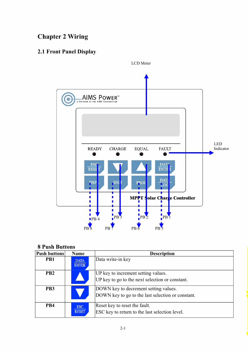
2.1 Front Panel Display
8 Push ButtonsPush buttons Name Description
PB1 Data write-in key
PB2 UP key to increment setting values.UP key to go to the next selection or constant.
PB3 DOWN key to decrement setting values.DOWN key to go to the last selection or constant.
PB4 Reset key to reset the fault.ESC key to return to the last selection level.
2-1
PB 1PB 2PB 3PB 4
PB 5PB 6PB 7PB 8
LED Indicator
LCD Meter
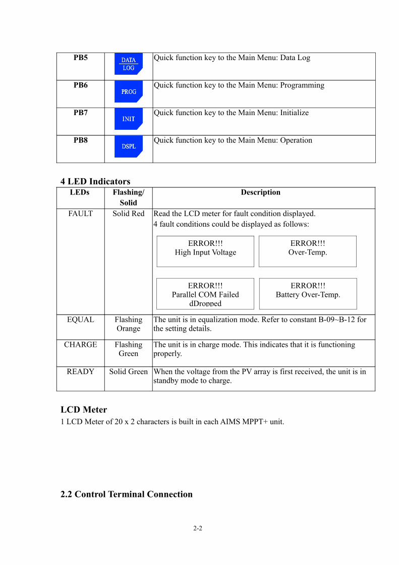
PB5 Quick function key to the Main Menu: Data Log
PB6 Quick function key to the Main Menu: Programming
PB7 Quick function key to the Main Menu: Initialize
PB8 Quick function key to the Main Menu: Operation
4 LED Indicators LEDs Flashing/
SolidDescription
FAULT Solid Red Read the LCD meter for fault condition displayed. 4 fault conditions could be displayed as follows:
EQUAL Flashing Orange
The unit is in equalization mode. Refer to constant B-09~B-12 for the setting details.
CHARGE Flashing Green
The unit is in charge mode. This indicates that it is functioning properly.
READY Solid Green When the voltage from the PV array is first received, the unit is in standby mode to charge.
LCD Meter1 LCD Meter of 20 x 2 characters is built in each AIMS MPPT+ unit.
2.2 Control Terminal Connection
2-2
ERROR!!!High Input Voltage
ERROR!!!Over-Temp.
ERROR!!!Parallel COM Failed
dDropped
ERROR!!!Battery Over-Temp.
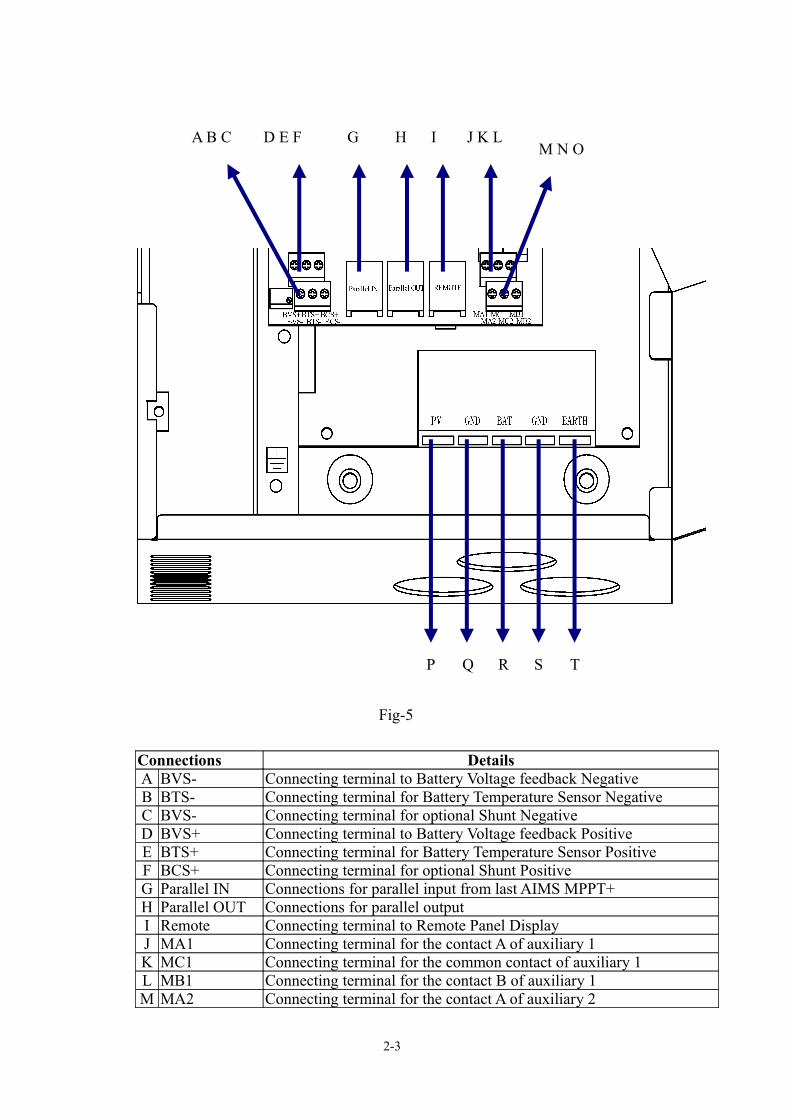
Fig-5
Connections DetailsA BVS- Connecting terminal to Battery Voltage feedback NegativeB BTS- Connecting terminal for Battery Temperature Sensor NegativeC BVS- Connecting terminal for optional Shunt NegativeD BVS+ Connecting terminal to Battery Voltage feedback PositiveE BTS+ Connecting terminal for Battery Temperature Sensor Positive F BCS+ Connecting terminal for optional Shunt PositiveG Parallel IN Connections for parallel input from last AIMS MPPT+H Parallel OUT Connections for parallel outputI Remote Connecting terminal to Remote Panel DisplayJ MA1 Connecting terminal for the contact A of auxiliary 1K MC1 Connecting terminal for the common contact of auxiliary 1L MB1 Connecting terminal for the contact B of auxiliary 1M MA2 Connecting terminal for the contact A of auxiliary 2
P Q R S T
2-3
M N OIHG J K LD E FA B C

N MC2 Connecting terminal for the common contact of auxiliary 2O MB2 Connecting terminal for the contact B of auxiliary 2P PV+ Connecting terminal for Solar Array PositiveQ GND Connecting terminal for Solar Array NegativeR BAT+ Connecting terminal for battery cable PositiveS GND Connecting terminal for battery cable NegativeT EARTH Connecting for ground
2-4
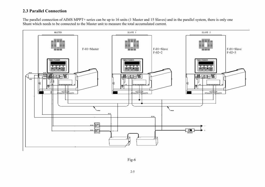
2.3 Parallel Connection
The parallel connection of AIMS MPPT+ series can be up to 16 units (1 Master and 15 Slaves) and in the parallel system, there is only one Shunt which needs to be connected to the Master unit to measure the total accumulated current.
2-5
Fig-6
F-01=Master F-01=SlaveF-02=2
F-01=SlaveF-02=3

2-6
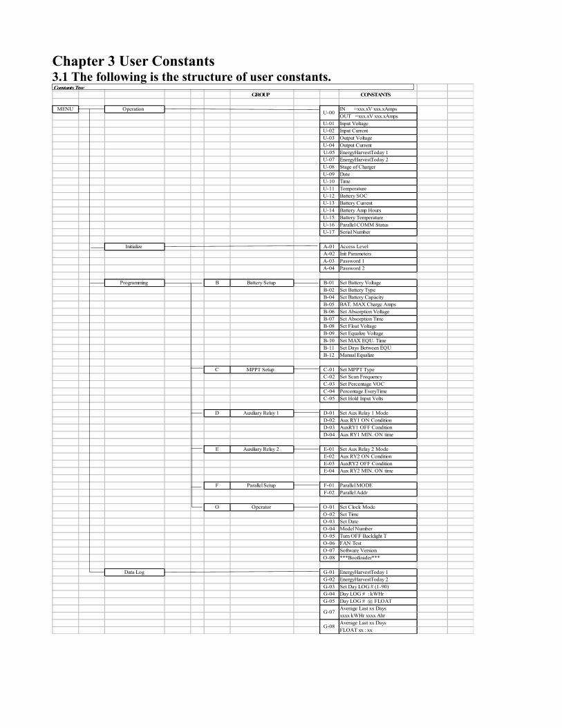
Chapter 3 User Constants3.1 The following is the structure of user constants.
GROUP CONSTANTS
MENU Operation IN =xxx.xV xxx.xAmpsOUT =xxx.xV xxx.xAmps
U-01 Input VoltageU-02 Input CurrentU-03 Output VoltageU-04 Output CurrentU-05 EnergyHarvestToday 1U-07 EnergyHarvestToday 2U-08 Stage of ChargerU-09 DateU-10 TimeU-11 TemperatureU-12 Battery SOCU-13 Battery CurrentU-14 Battery Amp HoursU-15 Battery TemperatureU-16 Parallel COMM StatusU-17 Serial Number
Initialize A-01 Access LevelA-02 Init ParametersA-03 Password 1A-04 Password 2
Programming B Battery Setup B-01 Set Battery VoltageB-02 Set Battery TypeB-04 Set Battery CapacityB-05 BAT. MAX Charge AmpsB-06 Set Absorption VoltageB-07 Set Absorption TimeB-08 Set Float VoltageB-09 Set Equalize VoltageB-10 Set MAX EQU. TimeB-11 Set Days Between EQUB-12 Manual Equalize
C MPPT Setup C-01 Set MPPT TypeC-02 Set Scan FrequencyC-03 Set Percentage VOCC-04 Percentage EveryTimeC-05 Set Hold Input Volts
D Auxiliary Relay 1 D-01 Set Aux Relay 1 ModeD-02 Aux RY1 ON ConditionD-03 AuxRY1 OFF ConditionD-04 Aux RY1 MIN. ON time
E Auxiliary Relay 2 E-01 Set Aux Relay 2 ModeE-02 Aux RY2 ON ConditionE-03 AuxRY2 OFF ConditionE-04 Aux RY2 MIN. ON time
F Parallel Setup F-01 Parallel MODEF-02 Parallel Addr
O Operator O-01 Set Clock ModeO-02 Set TimeO-03 Set DateO-04 Model NumberO-05 Turn OFF Backlight TO-06 FAN TestO-07 Software VersionO-08 ***Bootloader***
Data Log G-01 EnergyHarvestToday 1G-02 EnergyHarvestToday 2G-03 Set Day LOG # (1-90)G-04 Day LOG # : kWHrG-05 Day LOG # @ FLOAT
Average Last xx Daysxxxx kWHr xxxx AhrAverage Last xx DaysFLOAT xx : xx
U-00
G-07
G-08
Constants Tree
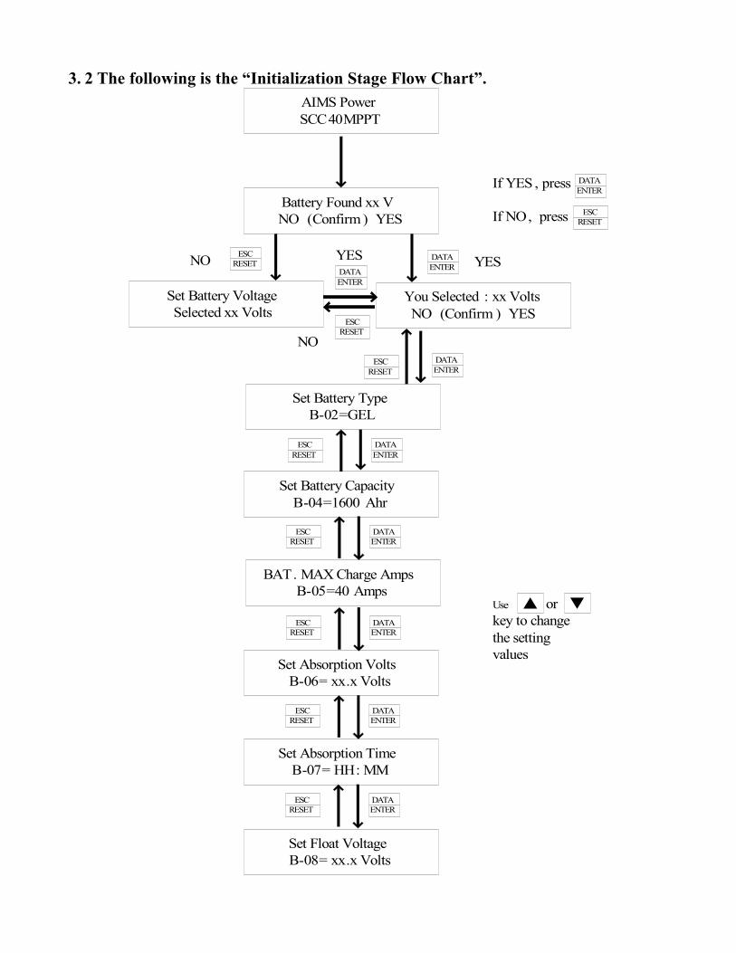
3. 2 The following is the “Initialization Stage Flow Chart”.AIMS PowerSCC40MPPT
Battery Found xx VNO (Confirm ) YES
You Selected : xx VoltsNO (Confirm ) YES
Set Battery VoltageSelected xx Volts
Set Battery TypeB-02=GEL
Set Battery CapacityB-04=1600 Ahr
BAT. MAX Charge AmpsB-05=40 Amps
Set Absorption VoltsB-06= xx.x Volts
Set Absorption TimeB-07= HH: MM
Set Float VoltageB-08= xx.x Volts
DATAENTER
DATAENTER
ESCRESET
DATAENTER
ESCRESET
DATAENTER
ESCRESET
DATAENTER
ESCRESET
DATAENTER
ESCRESET
ESCRESET
Use or key to change the setting values
NO ESCRESET YESDATA
ENTERYESDATAENTER
ESCRESET
NO
If YES , press
If NO, press
DATAENTER
ESCRESET
▼▲
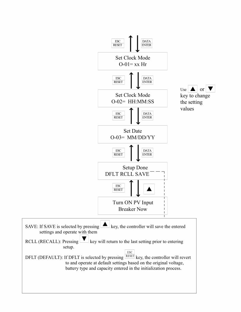
Set Clock ModeO-01= xx Hr
Set Clock ModeO-02= HH:MM:SS
Set DateO-03= MM/DD/YY
Setup Done DFLT RCLL SAVE
Turn ON PV InputBreaker Now
DATAENTER
ESCRESET
DATAENTER
ESCRESET
DATAENTER
ESCRESET
DATAENTER
ESCRESET
ESCRESET
▲
Use or key to change the setting values
▲ ▼
SAVE: If SAVE is selected by pressing ▲ key, the controller will save the entered settings and operate with them
RCLL (RECALL): Pressing ▼ key will return to the last setting prior to entering setup.
DFLT (DEFAULT): If DFLT is selected by pressing ESC
RESET key, the controller will revert to and operate at default settings based on the original voltage, battery type and capacity entered in the initialization process.

3.3 The following is the “Operation Stage Flow Chart”.
Main Menu
*** Main Menu ***Data Log
*** Main Menu ***Initialize
*** Main Menu ***Operation
*** Main Menu ***Programming
▼
▼
▼
▲
▲
▲
Main Menu-OperationMenu Constants
*** Main Menu ***Operation
DATAENTER IN=xxx.xV xxx .xAmps
OUT =xxx.xV xxx .xAmps
Input VoltageU-01=0.0 Volts
Input CurrentU-02=0.0 Amps
Output VoltageU-03=0.0 Volts
Stage of ChargerU-08= Charger OFF
EnergyHarvestToday 2U-07=00:00
TemperatureU-11= 0℃
Battery SOCU-12= 0%
Battery CurrentU-13= 0.0A
Battery Amp HoursU-14= 0 AHr
Battery TemperatureU-15= 0℃
Serial NumberU-17=000001
▲▼
▲
▲
▲
▲
▲
▲
▲
▲
▲
▲
▲
▲
▲
▼
▼
▼
▼
▼
▼
▼
▼
▼
▼
▼
▼
▼Output CurrentU-04=0.0 Amps
EnergyHarvestToday 100000 WHr 0000 AHr
Parallel COMM StatusU-16= SLAVE UNIT
DateU-09= 07/30/09
TimeU-10= HH:MM :SS
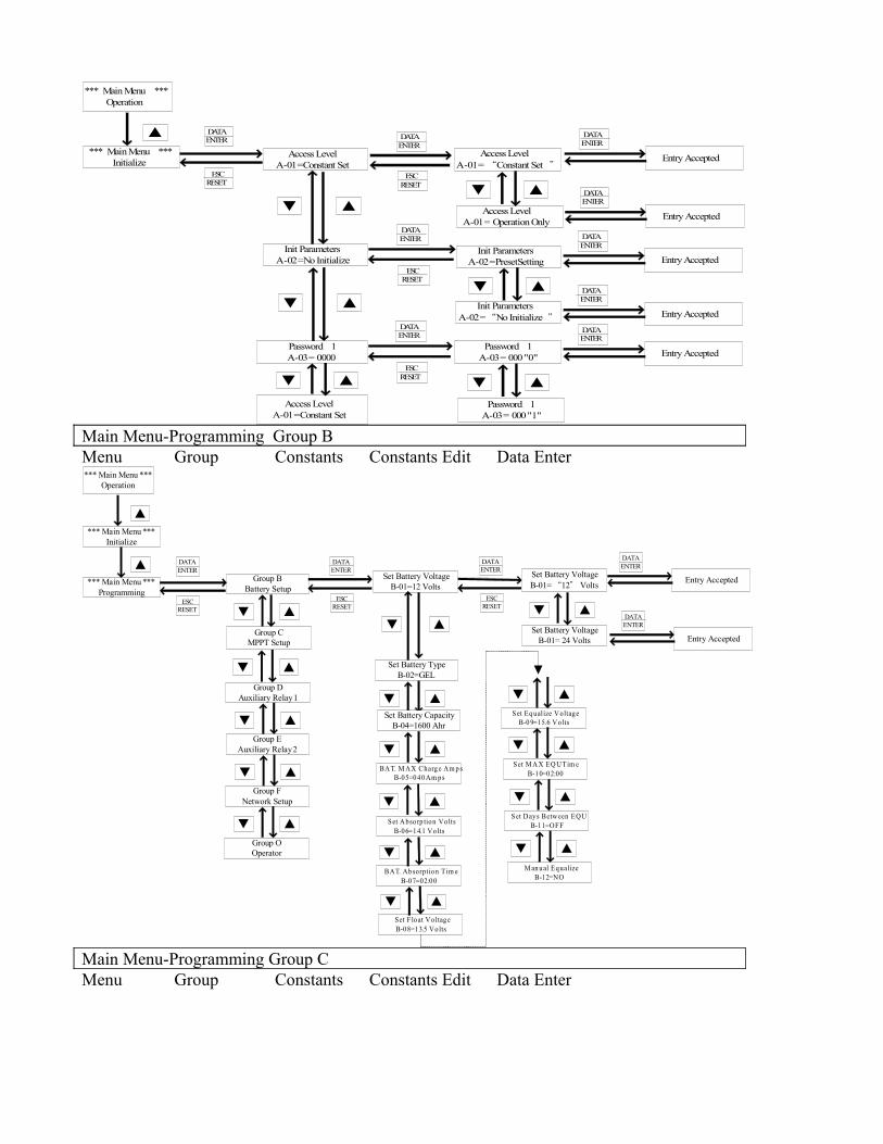
Main Menu-InitializeMenu Constants Constants Edit Data Enter
*** Main Menu ***Operation
DATAENTER
Access LevelA-01=Constant Set
*** Main Menu ***Initialize
Init ParametersA-02=No Initialize
Access LevelA-01= “Constant Set ”
Access LevelA-01= Operation Only
Init ParametersA-02=“No Initialize ”
Init ParametersA-02=PresetSetting
Password 1A-03= 0000
Password 1A-03= 000"0"
Password 1A-03= 000"1"
Access LevelA-01=Constant Set
▲
ESCRESET
DATAENTER
ESCRESET
DATAENTER
ESCRESET
DATAENTER
ESCRESET
▲▼
▲▼
▲▼
Entry Accepted
DATAENTER
Entry Accepted
DATAENTER
Entry Accepted
DATAENTER
Entry Accepted
DATAENTER
Entry Accepted
DATAENTER
▲▼
▲▼
▲▼
Main Menu-Programming Group BMenu Group Constants Constants Edit Data Enter*** Main Menu ***
Operation
DATAENTER
Group BBattery Setup
*** Main Menu ***Initialize
Set Battery TypeB-02=GEL
Set Battery VoltageB-01=12 Volts
Set Battery VoltageB-01= 24 Volts
BAT. M AX Charg e Am p sB-05=040 Am ps
▲
ESCRESET
DATAENTER
ESCRESET ▲▼
▲▼
Entry Accepted
DATAENTER
Entry Accepted
DATAENTER▲▼
▲▼
*** Main Menu ***Programming
▲
Group CMPPT Setup
Group DAuxiliary Relay 1
Group F Network Setup
Group EAuxiliary Relay 2
Group OOperator
▲▼
▲▼
▲▼
▲▼
▲▼
DATAENTER
ESCRESET
Set Battery VoltageB-01= “12” Volts
Set Battery CapacityB-04=1600 Ahr
Set F loat VoltageB-08=13.5 Volts
BAT. Ab sorption Tim eB-07=02:00
Set Abso rp tion VoltsB-06=14.1 Volts
▲▼
▲▼
Set Eq ualize VoltageB-0 9=15.6 Volts
Set M AX EQU. Tim eB-10=02:00
Set Days Between EQUB-11=OFF
M an ual EqualizeB-12=NO
▲▼
▲▼
▲▼
▲▼
▲▼
Main Menu-Programming Group CMenu Group Constants Constants Edit Data Enter
*** Main Menu ***Operation
DATAENTER
Group BBattery Setup
*** Main Menu ***Initialize
Set MPPT TypeC-01= P and O
Set MPPT TypeC-01=“P and O”
▲
ESCRESET
DATAENTER
ESCRESET ▲▼
Entry Accepted
DATAENTER
Entry Accepted
DATAENTER
▲▼
*** Main Menu ***Programming
▲
Group CMPPT Setup
Group DAuxiliary Relay 1
Group F Network Setup
Group EAuxiliary Relay 2
Group OOperator
▲▼
▲▼
▲▼
▲▼
▲▼
DATAENTER
ESCRESET
Set MPPT TypeC-01= Scan and Hold
Set Scan FrequencyC-02=01:00
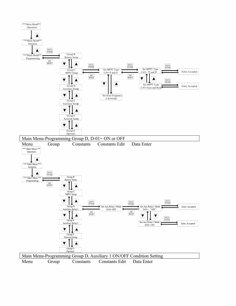
Main Menu-Programming Group D, D-01= ON or OFFMenu Group Constants Constants Edit Data Enter*** Main Menu ***
Operation
DATAENTER
Group BBattery Setup
*** Main Menu ***Initialize
Set Aux Relay 1 ModeD-01=OFF
▲
ESCRESET
DATAENTER
ESCRESET
Entry Accepted
DATAENTER
Entry Accepted
DATAENTER
*** Main Menu ***Programming
▲
Group CMPPT Setup
Group DAuxiliary Relay 1
Group F Network Setup
Group EAuxiliary Relay 2
Group OOperator
▲▼
▲▼
▲▼
▲▼
▲▼
DATAENTER
ESCRESET
Set Aux Relay 1 ModeD-01= “OFF”
Set Aux Relay 1 ModeD-01= ON
▼ ▼
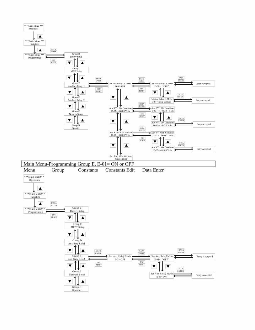
Main Menu-Programming Group D, Auxiliary 1 ON/OFF Condition SettingMenu Group Constants Constants Edit Data Enter
*** Main Menu ***Operation
DATAENTER
Group BBattery Setup
*** Main Menu ***Initialize
Set Aux Relay 1 ModeD-01=OFF
▲
ESCRESET
DATAENTER
ESCRESET
Entry Accepted
DATAENTER
Entry Accepted
DATAENTER
*** Main Menu ***Programming
▲
Group CMPPT Setup
Group DAuxiliary Relay 1
Group F Network Setup
Group EAuxiliary Relay 2
Group OOperator
▲▼
▲▼
▲▼
▲▼
▲▼
DATAENTER
ESCRESET
Set Aux Relay 1 ModeD-01= “OFF”
Set Aux Relay 1 ModeD-01= Solar Voltage
▲▼
▲▼
Aux RY 1 ON ConditionD-02= <000.0 Volts
DATAENTER
ESCRESET
Aux RY1 ON ConditionD-02= <“000.0”Volts
▲▼
Aux RY1 ON ConditionD-02=< 010.0 Volts Entry Accepted
DATAENTER▲▼
Aux RY1 OFF ConditionD-03= <000.0 Volts
DATAENTER
ESCRESET
Aux RY1 OFF ConditionD-03= >“000.0”Volts
▲▼
Entry Accepted
DATAENTER
Aux RY 1 ON ConditionD-03=> 016.0 Volts
▲▼
Aux RY1 MIN. ON timeD-04= 00:00
Main Menu-Programming Group E, E-01= ON or OFFMenu Group Constants Constants Edit Data Enter*** Main Menu ***
Operation
DATAENTER
Group BBattery Setup
*** M ain Menu ***Initialize
Set Aux Relay 2 ModeE-01=OFF
▲
ESCRESET
DATAENTER
ESCRESET
Entry Accepted
DATAENTER
Entry Accepted
DATAENTER
*** M ain Menu ***Programming
▲
Group CMPPT Setup
Group DAuxiliary Relay 1
Group F Network Setup
Group EAuxiliary Relay 2
Group OOperator
▲▼
▲▼
▲▼
▲▼
▲▼
DATAENTER
ESCRESET
Set Aux Relay 2 ModeE-01= “OFF”
Set Aux Relay 2 ModeE-01= ON
▼ ▼
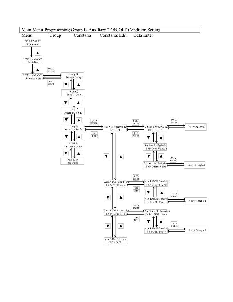
Main Menu-Programming Group E, Auxiliary 2 ON/OFF Condition SettingMenu Group Constants Constants Edit Data Enter*** Main Menu ***
Operation
DATAENTER
Group BBattery Setup
*** Main M enu ***Initialize
Set Aux Relay 2 ModeE-01=OFF
▲
ESCRESET
DATAENTER
ESCRESET
E ntry Accepted
DATAENTER
*** Main M enu ***Program m ing
▲
Group CMPPT Setup
G roup DAuxiliary Relay 1
Group F Network Setup
Group EAuxiliary Relay 2
Group OOperator
▲▼
▲▼
▲▼
▲▼
▲▼
DATAENTER
ESCRESET
Set Aux Relay 2 ModeE-01= “OFF”
Set Aux Relay 2 M odeE-01= Solar Voltage
▲▼
Aux RY2 ON ConditionE-02= <000.0 Volts
DATAENTER
ESCRESET
Aux RY2 ON ConditionE-02= <“0 00.0”V o lts
▲▼
Aux RY2 ON ConditionE-02=< 011.0 Volts Entry Accepted
DATAENTER▲▼
A u x R Y2 O F F C on d itionE-03= <000.0 Volts
DATAENTER
ESCRESET
A u x R Y2 O F F C on ditio nE-0 3= >“0 0 0.0”V o lts
▲▼
Entry Accepted
DATAENTER
Aux RY2 ON ConditionD-03=> 014.4 Volts
▲▼
A u x R Y2 M IN. O N tim eE-04= 00:00
▲▼
Set Aux Relay 2 ModeE-01= Output Volts Entry Accepted
DATAENTER
▼ ▲
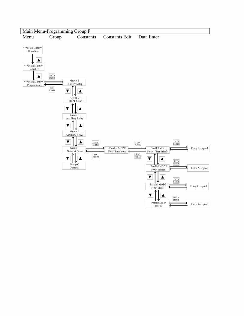
Main Menu-Programming Group FMenu Group Constants Constants Edit Data Enter
*** Main Menu ***Operation
DATAENTER
Group BBattery Setup
*** Main Menu ***Initialize
Parallel MODEF-01= Standalone
▲
ESCRESET
DATAENTER
ESCRESET
Entry Accepted
DATAENTER
Entry Accepted
DATAENTER
*** Main Menu ***Programming
▲
Group CMPPT Setup
Group DAuxiliary Relay 1
Group F Network Setup
Group EAuxiliary Relay 2
Group OOperator
▲▼
▲▼
▲▼
▲▼
▲▼ DATAENTER
ESCRESET
Parallel MODEF-01= “Standalone”
Parallel MODEF-01= Master
Parallel MODEF-01= Slave
▲▼
▲▼
Entry Accepted
DATAENTER
Parallel AddrF-02= 02
▲▼
Entry Accepted
DATAENTER
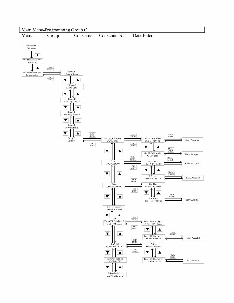
Main Menu-Programming Group OMenu Group Constants Constants Edit Data Enter
*** Main Menu ***Operation
DATAENTER
Group BBattery Setup
*** Main Menu ***Initialize
Set CLOCK ModeO-01= 12Hr
▲
ESCRESET
DATAENTER
ESCRESET
Entry Accepted
DATAENTER
Entry Accepted
DATAENTER
*** Main Menu ***Programming
▲
Group CMPPT Setup
Group DAuxiliary Relay 1
Group F Network Setup
Group EAuxiliary Relay 2
Group OOperator
▲▼
▲▼
▲▼
▲▼
▲▼
DATAENTER
ESCRESET
Set CLOCK ModeO-01= “12”Hr
Set CLOCK ModeO-01= 24Hr
▲▼
TimeO-02=00:00:00
▲▼
DATAENTER
ESCRESET
Set TimeO-02= “00” : 00: 00
Set TimeO-02=01: “00”:00
▲▼
▲▼
DateO-03=00/00/00
DATAENTER
ESCRESET
Set DateO-03= “00”/00/00
▲▼
Set DateO-03= 01/ “00"/00
▲▼
Model NumberO-04=SCC40MPP
DATAENTER
ESCRESET
Turn OFF Backlight TO-05= “10” Minutes
Turn OFF Backlight TO-05= 9 Minutes
▲▼
Turn OFF Backlight TO-05=10 Minutes
▲▼
FAN testO-06=10 FAN OFF
DATAENTER
ESCRESET
FAN testO-06= “FAN OFF”
Turn OFF Backlight TO-06= FAN ON
▲▼
▲▼
Software VersionO-07=09.31I
▲▼
Entry Accepted
DATAENTER
Entry Accepted
Entry Accepted
Entry Accepted
DATAENTER
Entry Accepted
DATAENTER
***Bootloader ***Load New Software !
▲▼
DATAENTER
DATAENTER
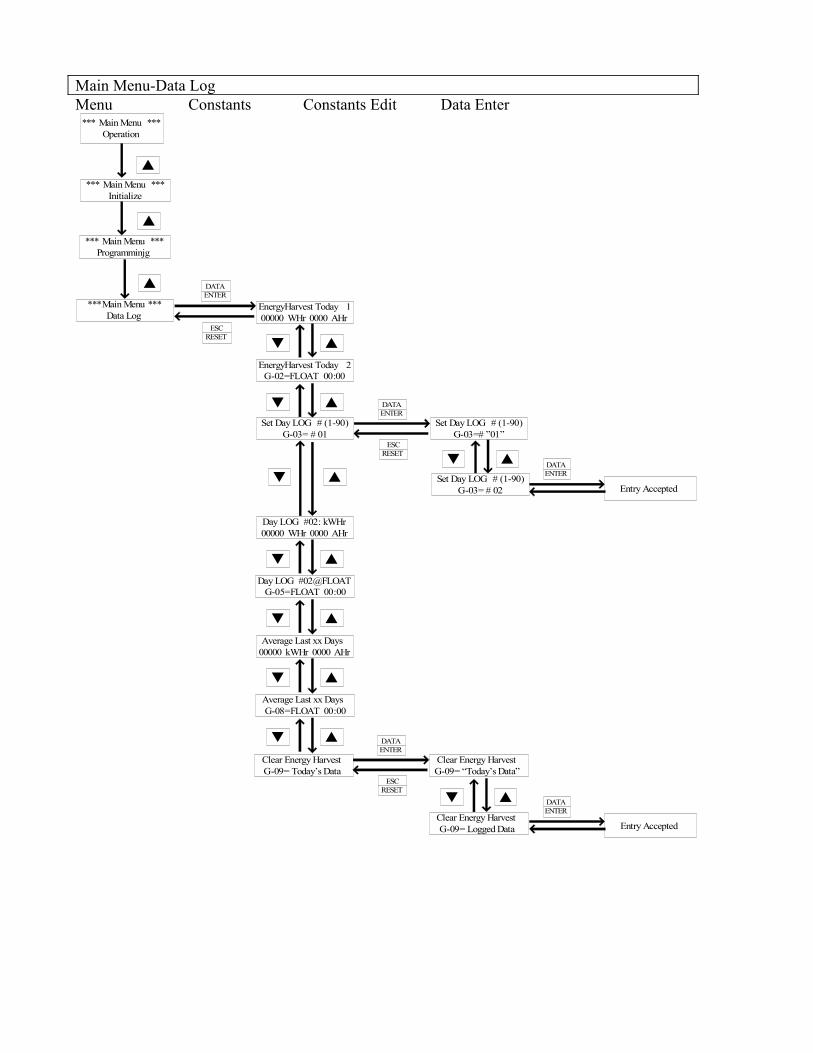
Main Menu-Data LogMenu Constants Constants Edit Data Enter
*** Main Menu ***Operation
EnergyHarvest Today 100000 WHr 0000 AHr
*** Main Menu ***Initialize
***Main Menu ***Data Log
▲
DATAENTER
ESCRESET
DATAENTER
ESCRESET
▲▼
Entry Accepted
DATAENTER▲▼
▲
*** Main Menu ***Programminjg
▲
EnergyHarvest Today 2G-02=FLOAT 00:00
▲▼
Set Day LOG # (1-90)G-03= # 01
Set Day LOG # (1-90)G-03=# ”01”
▲▼
Set Day LOG # (1-90)G-03= # 02
Day LOG #02: kWHr00000 WHr 0000 AHr
▲▼
Day LOG #02@FLOATG-05=FLOAT 00:00
▲▼
Average Last xx Days00000 kWHr 0000 AHr
▲▼
Average Last xx DaysG-08=FLOAT 00:00
▲▼
Clear Energy HarvestG-09= Today’s Data
Clear Energy HarvestG-09= “Today’s Data”
Entry Accepted
DATAENTER
▲▼
Clear Energy HarvestG-09= Logged Data
DATAENTER
ESCRESET
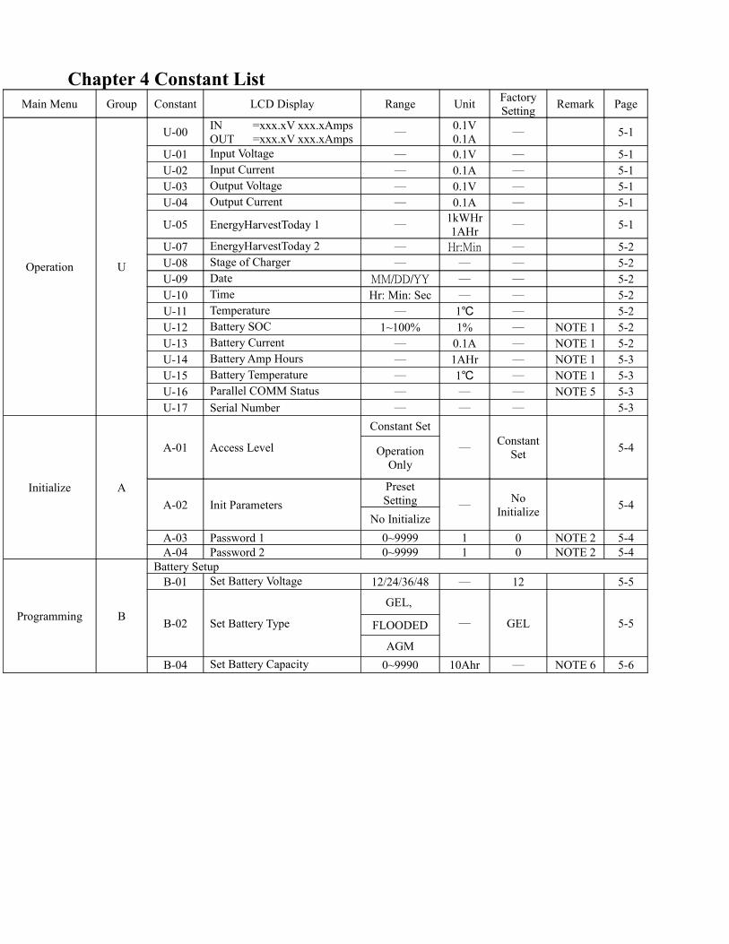
Chapter 4 Constant ListMain Menu Group Constant LCD Display Range Unit Factory
Setting Remark Page
Operation U
U-00 INOUT
=xxx.xV xxx.xAmps =xxx.xV xxx.xAmps ─
0.1V0.1A ─ 5-1
U-01 Input Voltage ─ 0.1V ─ 5-1U-02 Input Current ─ 0.1A ─ 5-1U-03 Output Voltage ─ 0.1V ─ 5-1U-04 Output Current ─ 0.1A ─ 5-1
U-05 EnergyHarvestToday 1 ─1kWHr1AHr ─ 5-1
U-07 EnergyHarvestToday 2 ─ Hr:Min ─ 5-2U-08 Stage of Charger ─ ─ ─ 5-2U-09 Date MM/DD/YY ─ ─ 5-2U-10 Time Hr: Min: Sec ─ ─ 5-2U-11 Temperature ─ 1℃ ─ 5-2U-12 Battery SOC 1~100% 1% ─ NOTE 1 5-2U-13 Battery Current ─ 0.1A ─ NOTE 1 5-2U-14 Battery Amp Hours ─ 1AHr ─ NOTE 1 5-3U-15 Battery Temperature ─ 1℃ ─ NOTE 1 5-3U-16 Parallel COMM Status ─ ─ ─ NOTE 5 5-3U-17 Serial Number ─ ─ ─ 5-3
Initialize A
A-01 Access Level
Constant Set
─Constant
Set 5-4Operation Only
A-02 Init ParametersPreset Setting ─
No Initialize 5-4
No InitializeA-03 Password 1 0~9999 1 0 NOTE 2 5-4A-04 Password 2 0~9999 1 0 NOTE 2 5-4
Programming B
Battery SetupB-01 Set Battery Voltage 12/24/36/48 ─ 12 5-5
B-02 Set Battery Type
GEL,
─ GEL 5-5FLOODED
AGMB-04 Set Battery Capacity 0~9990 10Ahr ─ NOTE 6 5-6
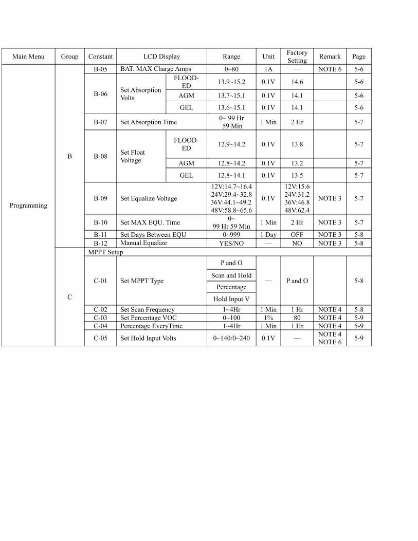
Main Menu Group Constant LCD Display Range Unit FactorySetting Remark Page
Programming
B
B-05 BAT. MAX Charge Amps 0~80 1A ─ NOTE 6 5-6
B-06 Set AbsorptionVolts
FLOOD-ED 13.9~15.2 0.1V 14.6 5-6
AGM 13.7~15.1 0.1V 14.1 5-6
GEL 13.6~15.1 0.1V 14.1 5-6
B-07 Set Absorption Time 0~ 99 Hr 59 Min 1 Min 2 Hr 5-7
B-08 Set Float Voltage
FLOOD-ED 12.9~14.2 0.1V 13.8 5-7
AGM 12.8~14.2 0.1V 13.2 5-7
GEL 12.8~14.1 0.1V 13.5 5-7
B-09 Set Equalize Voltage
12V:14.7~16.424V:29.4~32.836V:44.1~49.248V:58.8~65.6
0.1V
12V:15.624V:31.236V:46.848V:62.4
NOTE 3 5-7
B-10 Set MAX EQU. Time 0~99 Hr 59 Min 1 Min 2 Hr NOTE 3 5-7
B-11 Set Days Between EQU 0~999 1 Day OFF NOTE 3 5-8B-12 Manual Equalize YES/NO ─ NO NOTE 3 5-8
C
MPPT Setup
C-01 Set MPPT Type
P and O
─ P and O 5-8Scan and Hold
Percentage
Hold Input VC-02 Set Scan Frequency 1~4Hr 1 Min 1 Hr NOTE 4 5-8C-03 Set Percentage VOC 0~100 1% 80 NOTE 4 5-9C-04 Percentage EveryTime 1~4Hr 1 Min 1 Hr NOTE 4 5-9
C-05 Set Hold Input Volts 0~140/0~240 0.1V ─NOTE 4NOTE 6 5-9
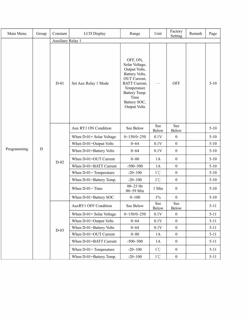
Main Menu Group Constant LCD Display Range Unit FactorySetting Remark Page
Programming D
Auxiliary Relay 1
D-01 Set Aux Relay 1 Mode
OFF, ON, Solar Voltage,Output Volts, Battery Volts, OUT Current,BATT Current, Temperature
Battery Temp.Time
Battery SOC,Output Volts
─ OFF 5-10
D-02
Aux RY1 ON Condition See Below See Below
See Below 5-10
When D-01= Solar Voltage 0~150/0~250 0.1V 0 5-10
When D-01=Output Volts 0~64 0.1V 0 5-10
When D-01=Battery Volts 0~64 0.1V 0 5-10
When D-01=OUT Current 0~80 1A 0 5-10
When D-01=BATT Current -500~500 1A 0 5-10When D-01= Temperature -20~100 1℃ 0 5-10
When D-01=Battery Temp. -20~100 1℃ 0 5-10
When D-01= Time 00~23 Hr00~59 Min 1 Min 0 5-10
When D-01=Battery SOC 0~100 1% 0 5-10
D-03
AuxRY1 OFF Condition See Below See Below
See Below 5-11
When D-01= Solar Voltage 0~150/0~250 0.1V 0 5-11
When D-01=Output Volts 0~64 0.1V 0 5-11
When D-01=Battery Volts 0~64 0.1V 0 5-11When D-01=OUT Current 0~80 1A 0 5-11
When D-01=BATT Current -500~500 1A 0 5-11
When D-01= Temperature -20~100 1℃ 0 5-11
When D-01=Battery Temp. -20~100 1℃ 0 5-11
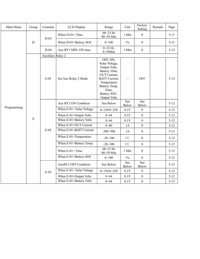
Main Menu Group Constant LCD Display Range Unit FactorySetting Remark Page
Programming
DD-03
When D-01= Time 00~23 Hr00~59 Min 1 Min 0 5-11
When D-01=Battery SOC 0~100 1% 0 5-11
D-04 Aux RY1 MIN. ON time 0~23 Hr, 0~59Min 1 Min 0 5-12
E
Auxiliary Relay 2
E-01 Set Aux Relay 2 Mode
OFF, ON, Solar Voltage,Output Volts, Battery Volts, OUT Current,BATT Current, Temperature
Battery Temp.Time,
Battery SOC,Output Volts
─ OFF 5-12
E-02
Aux RY2 ON Condition See Below See Below
See Below 5-12
When E-01= Solar Voltage 0~150/0~250 0.1V 0 5-12
When E-01=Output Volts 0~64 0.1V 0 5-12When E-01=Battery Volts 0~64 0.1V 0 5-12When E-01=OUT Current 0~80 1A 0 5-12When E-01=BATT Current -500~500 1A 0 5-12When E-01=Temperature -20~100 1℃ 0 5-12When E-01=Battery Temp. -20~100 1℃ 0 5-12
When E-01= Time 00~23 Hr00~59 Min 1 Min 0 5-12
When E-01=Battery SOC 0~100 1% 0 5-12
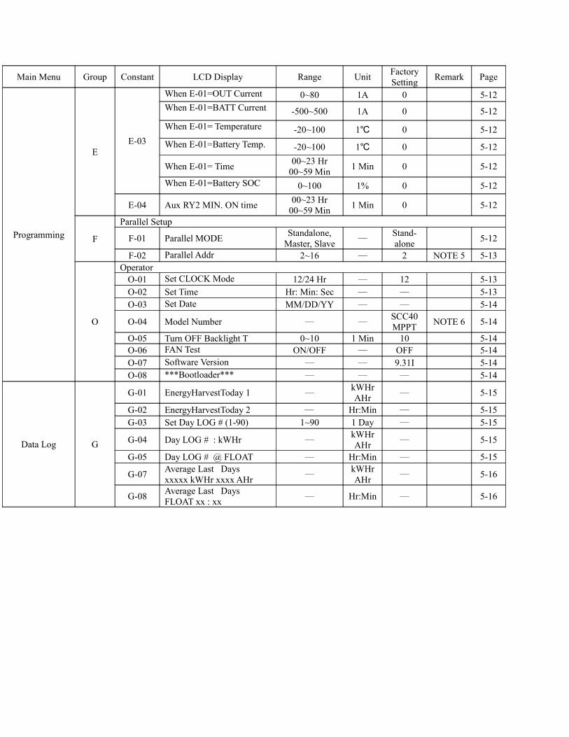
E-03
AuxRY2 OFF Condition See Below See Below
See Below 5-12
When E-01= Solar Voltage 0~150/0~250 0.1V 0 5-12When E-01=Output Volts 0~64 0.1V 0 5-12When E-01=Battery Volts 0~64 0.1V 0 5-12
Main Menu Group Constant LCD Display Range Unit FactorySetting Remark Page
Programming
EE-03
When E-01=OUT Current 0~80 1A 0 5-12When E-01=BATT Current -500~500 1A 0 5-12When E-01= Temperature -20~100 1℃ 0 5-12When E-01=Battery Temp. -20~100 1℃ 0 5-12
When E-01= Time 00~23 Hr00~59 Min 1 Min 0 5-12
When E-01=Battery SOC 0~100 1% 0 5-12
E-04 Aux RY2 MIN. ON time 00~23 Hr 00~59 Min 1 Min 0 5-12
F
Parallel Setup
F-01 Parallel MODE Standalone, Master, Slave ─
Stand-alone 5-12
F-02 Parallel Addr 2~16 ─ 2 NOTE 5 5-13
O
OperatorO-01 Set CLOCK Mode 12/24 Hr ─ 12 5-13O-02 Set Time Hr: Min: Sec ─ ─ 5-13O-03 Set Date MM/DD/YY ─ ─ 5-14
O-04 Model Number ─ ─SCC40MPPT NOTE 6 5-14
O-05 Turn OFF Backlight T 0~10 1 Min 10 5-14O-06 FAN Test ON/OFF ─ OFF 5-14O-07 Software Version ─ ─ 9.31I 5-14O-08 ***Bootloader*** ─ ─ ─ 5-14
Data Log G
G-01 EnergyHarvestToday 1 ─kWHrAHr ─ 5-15
G-02 EnergyHarvestToday 2 ─ Hr:Min ─ 5-15G-03 Set Day LOG # (1-90) 1~90 1 Day ─ 5-15
G-04 Day LOG # : kWHr ─kWHrAHr ─ 5-15
G-05 Day LOG # @ FLOAT ─ Hr:Min ─ 5-15
G-07 Average Last Daysxxxxx kWHr xxxx AHr ─
kWHrAHr ─ 5-16
G-08 Average Last DaysFLOAT xx : xx ─ Hr:Min ─ 5-16
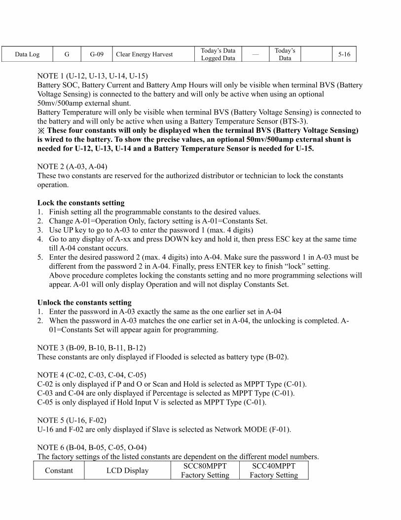
Data Log G G-09 Clear Energy Harvest Today’s DataLogged Data ─
Today’s Data 5-16
NOTE 1 (U-12, U-13, U-14, U-15)Battery SOC, Battery Current and Battery Amp Hours will only be visible when terminal BVS (Battery Voltage Sensing) is connected to the battery and will only be active when using an optional 50mv/500amp external shunt.Battery Temperature will only be visible when terminal BVS (Battery Voltage Sensing) is connected to the battery and will only be active when using a Battery Temperature Sensor (BTS-3).
These four constants will only be displayed when the terminal BVS (Battery Voltage Sensing)※ is wired to the battery. To show the precise values, an optional 50mv/500amp external shunt is needed for U-12, U-13, U-14 and a Battery Temperature Sensor is needed for U-15.
NOTE 2 (A-03, A-04)These two constants are reserved for the authorized distributor or technician to lock the constants operation.
Lock the constants setting 1. Finish setting all the programmable constants to the desired values.2. Change A-01=Operation Only, factory setting is A-01=Constants Set.3. Use UP key to go to A-03 to enter the password 1 (max. 4 digits)4. Go to any display of A-xx and press DOWN key and hold it, then press ESC key at the same time
till A-04 constant occurs.5. Enter the desired password 2 (max. 4 digits) into A-04. Make sure the password 1 in A-03 must be
different from the password 2 in A-04. Finally, press ENTER key to finish “lock” setting. Above procedure completes locking the constants setting and no more programming selections will appear. A-01 will only display Operation and will not display Constants Set.
Unlock the constants setting 1. Enter the password in A-03 exactly the same as the one earlier set in A-042. When the password in A-03 matches the one earlier set in A-04, the unlocking is completed. A-
01=Constants Set will appear again for programming.
NOTE 3 (B-09, B-10, B-11, B-12)These constants are only displayed if Flooded is selected as battery type (B-02).
NOTE 4 (C-02, C-03, C-04, C-05)C-02 is only displayed if P and O or Scan and Hold is selected as MPPT Type (C-01). C-03 and C-04 are only displayed if Percentage is selected as MPPT Type (C-01). C-05 is only displayed if Hold Input V is selected as MPPT Type (C-01).
NOTE 5 (U-16, F-02)U-16 and F-02 are only displayed if Slave is selected as Network MODE (F-01).
NOTE 6 (B-04, B-05, C-05, O-04)The factory settings of the listed constants are dependent on the different model numbers.
Constant LCD Display SCC80MPPTFactory Setting
SCC40MPPTFactory Setting

B-04 Set Battery Capacity 1600 Ahr 800 AhrB-05 Bat. MAX Charge Amps 80A 40AC-05 Set Hold Input Volts 240Vdc 240VdcO-04 Model Number SCC80MPPT SCC40MPPT
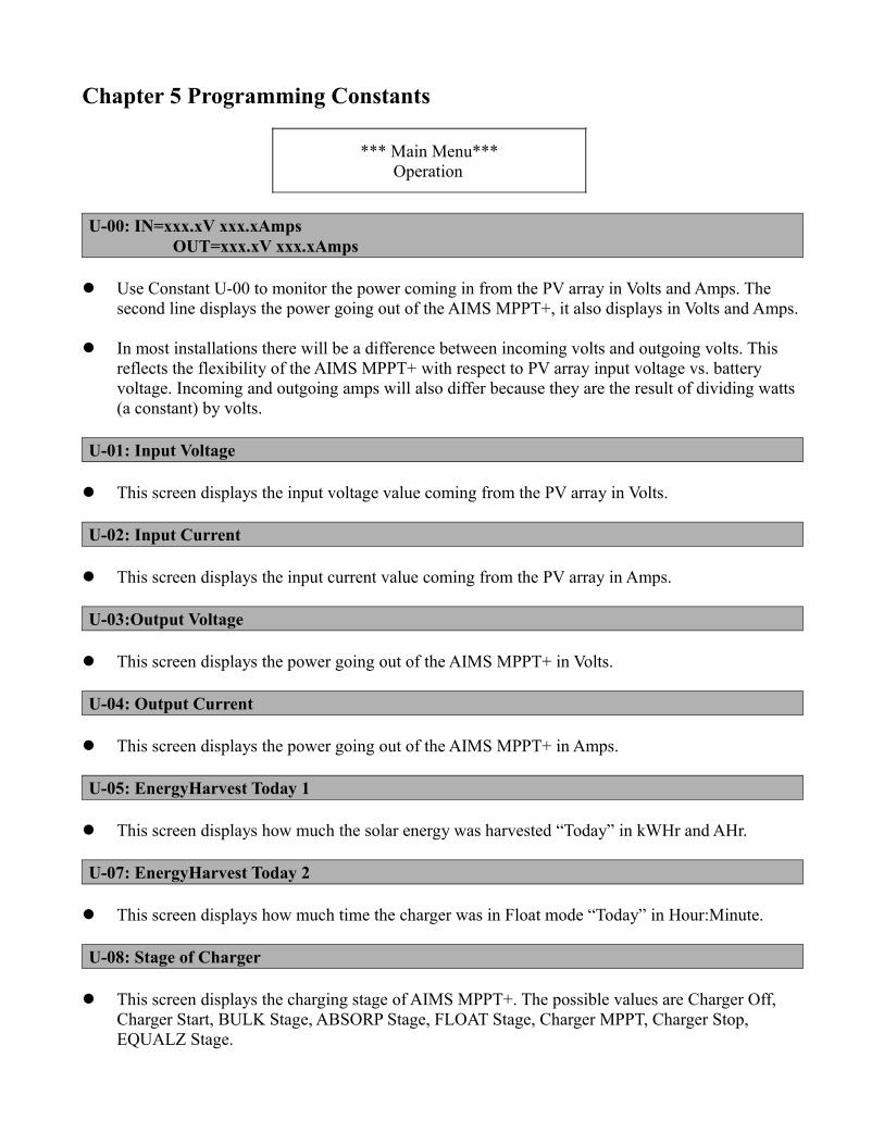
Chapter 5 Programming Constants
*** Main Menu***Operation
U-00: IN=xxx.xV xxx.xAmps OUT=xxx.xV xxx.xAmps
Use Constant U-00 to monitor the power coming in from the PV array in Volts and Amps. The second line displays the power going out of the AIMS MPPT+, it also displays in Volts and Amps.
In most installations there will be a difference between incoming volts and outgoing volts. This reflects the flexibility of the AIMS MPPT+ with respect to PV array input voltage vs. battery voltage. Incoming and outgoing amps will also differ because they are the result of dividing watts (a constant) by volts.
U-01: Input Voltage
This screen displays the input voltage value coming from the PV array in Volts.
U-02: Input Current
This screen displays the input current value coming from the PV array in Amps.
U-03:Output Voltage
This screen displays the power going out of the AIMS MPPT+ in Volts.
U-04: Output Current
This screen displays the power going out of the AIMS MPPT+ in Amps.
U-05: EnergyHarvest Today 1
This screen displays how much the solar energy was harvested “Today” in kWHr and AHr.
U-07: EnergyHarvest Today 2
This screen displays how much time the charger was in Float mode “Today” in Hour:Minute.
U-08: Stage of Charger
This screen displays the charging stage of AIMS MPPT+. The possible values are Charger Off, Charger Start, BULK Stage, ABSORP Stage, FLOAT Stage, Charger MPPT, Charger Stop, EQUALZ Stage.

U-09: Date
This screen displays the date according to the setting of initialization stage. The display format is MM/DD/YY.
U-10: Time
This screen displays the time according to the setting of initialization stage.
U-11: Temperature
This screen displays the temperature detected in AIMS MPPT+ Battery Charger.
U-12: Battery SOC
This screen displays the State Of Charge (SOC) as a percentage of fully charged. SOC will only be visible when terminal BVS (Battery Voltage Sensing) is connected to the battery and will only be active when using an optional 50mv/500amp external shunt.
U-12 will only be displayed when the terminal BVS (Battery Voltage Sensing) is wired to the※ battery. To show the precise values, an optional 50mv/500amp external shunt is needed.
U-13: Battery Current
This screen displays the battery current in Amps. Battery Current will only be visible when terminal BVS (Battery Voltage Sensing) is connected to the battery and will only be active when using an optional 50mv/500amp external shunt.
U-13 will only be displayed when the terminal BVS (Battery Voltage Sensing) is wired to the※ battery. To show the precise values, an optional 50mv/500amp external shunt is needed.
U-14: Battery Amp Hours
This screen displays the battery capacity in AHr (Amp Hours). Battery Amp Hours will only be visible when terminal BVS (Battery Voltage Sensing) is connected to the battery and will only be active when using an optional 50mv/500amp external shunt.
U-14 will only be displayed when the terminal BVS (Battery Voltage Sensing) is wired to the※ battery. To show the precise values, an optional 50mv/500amp external shunt is needed.
U-15: Battery Temperature
This screen displays the battery temperature in . ℃ Battery Temperature will only be visible when Battery Voltage Sensor is connected and will only be active when using a Battery Temperature Sensor (BTS-3).
U-15 will only be displayed when the terminal BVS (Battery Voltage Sensing) is wired to the※ battery. To show the precise values, a Battery Temperature Sensor (BTS-3) is needed to be wired to terminal BTS.
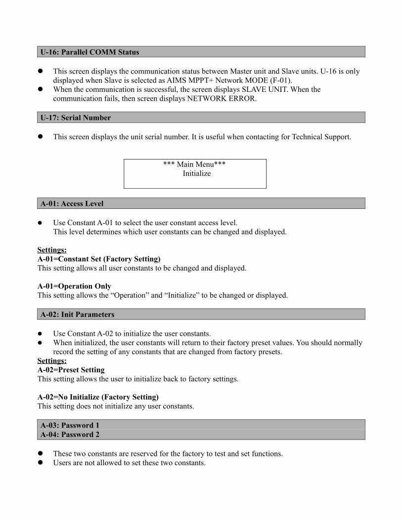
U-16: Parallel COMM Status
This screen displays the communication status between Master unit and Slave units. U-16 is only displayed when Slave is selected as AIMS MPPT+ Network MODE (F-01).
When the communication is successful, the screen displays SLAVE UNIT. When the communication fails, then screen displays NETWORK ERROR.
U-17: Serial Number
This screen displays the unit serial number. It is useful when contacting for Technical Support.
*** Main Menu***Initialize
A-01: Access Level
Use Constant A-01 to select the user constant access level. This level determines which user constants can be changed and displayed.
Settings:A-01=Constant Set (Factory Setting)This setting allows all user constants to be changed and displayed.
A-01=Operation OnlyThis setting allows the “Operation” and “Initialize” to be changed or displayed.
A-02: Init Parameters
Use Constant A-02 to initialize the user constants. When initialized, the user constants will return to their factory preset values. You should normally
record the setting of any constants that are changed from factory presets.Settings:A-02=Preset Setting This setting allows the user to initialize back to factory settings.
A-02=No Initialize (Factory Setting)This setting does not initialize any user constants.
A-03: Password 1A-04: Password 2
These two constants are reserved for the factory to test and set functions. Users are not allowed to set these two constants.
Lock the constants setting 1. Finish setting all the programmable constants to the desired values.2. Change A-01=Operation Only, factory setting is A-01=Constants Set.3. Use UP key to go to A-03 to enter the password 1 (max. 4 digits)4. Go to any display of A-xx and press DOWN key and hold it, then press ESC key at the same time
until A-04 constant occurs.5. Enter the desired password 2 (max. 4 digits) into A-04. Make sure the password 1 in A-03 must be
different from the password 2 in A-04. Finally, press ENTER key to finish “lock” setting. Above procedure completes locking the constants setting and no more programming selection will appear. A-01 will only display Operation and will not display Constants Set.
Unlock the constants setting 1. Enter the password in A-03 exactly the same as the one earlier set in A-042. When the password in A-03 matches the one earlier set in A-04, the unlocking is completed. A-
01=Constants Set would appear again for programming.
*** Main Menu***Programming
Group BBattery Setup
B-01: Set Battery Voltage
During initialization of AIMS MPPT+, it will detect and ask the installer to confirm the battery voltage found is correct. In almost all circumstance the AIMS MPPT+ will correctly detect battery voltage.
Use Constant B-01 to change the battery voltage if the battery voltage displayed by the AIMS MPPT+ is different from the installed batteries. The selection range of the battery voltage is 12V (Factory Setting), 24V, 36V and 48V.
B-02: Set Battery Type
Use UP or DOWN keys to allow the installer to change what type of batteries it is connected to (Flooded, Gel, AGM) AIMS MPPT+. The default “BATTERY TYPE” is GEL
Please be sure to select the type which matches the system’s batteries. This setting controls battery charging voltages in B-06 and B-08.
B-04: Set Battery Capacity
This setting controls battery charging amperages and other settings. The factory setting for CAPACITY is 800 amp hours for SCC40MPPT and1600 amp hours for SCC80MPPT.
At full output capacity a SCC80MPPT can deliver 80 amps to a battery, this amount of amperage (current) is equal to the C/10 (capacity divided by ten) rate of a 1600 amp hour battery and, as
such meets most manufacturers recommendations for minimum PV charging capacity. In applications with battery banks under 1600 amp hours it is recommended to lower the
Maximum Charge Rate setting from the default 80 amps to the C10 rate of the battery bank.
B-05: BAT. MAX Charge Amps
Use Constant B-05 to allow the installer to limit the maximum charge amps allowed to the batteries. The factory setting is 40 amps (SCC40MPPT).
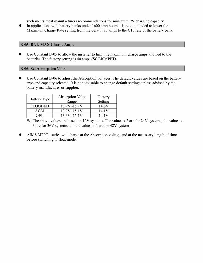
B-06: Set Absorption Volts
Use Constant B-06 to adjust the Absorption voltages. The default values are based on the battery type and capacity selected. It is not advisable to change default settings unless advised by the battery manufacturer or supplier.
Battery Type Absorption Volts Range
FactorySetting
FLOODED 13.9V~15.2V 14.6VAGM 13.7V~15.1V 14.1VGEL 13.6V~15.1V 14.1V
※ The above values are based on 12V systems. The values x 2 are for 24V systems; the values x 3 are for 36V systems and the values x 4 are for 48V systems.
AIMS MPPT+ series will charge at the Absorption voltage and at the necessary length of time before switching to float mode.
B-07: Set Absorption Time
Use Constant B-07 to adjust the length of Absorption time. The factory setting is 2 hours (displayed as 02:00).
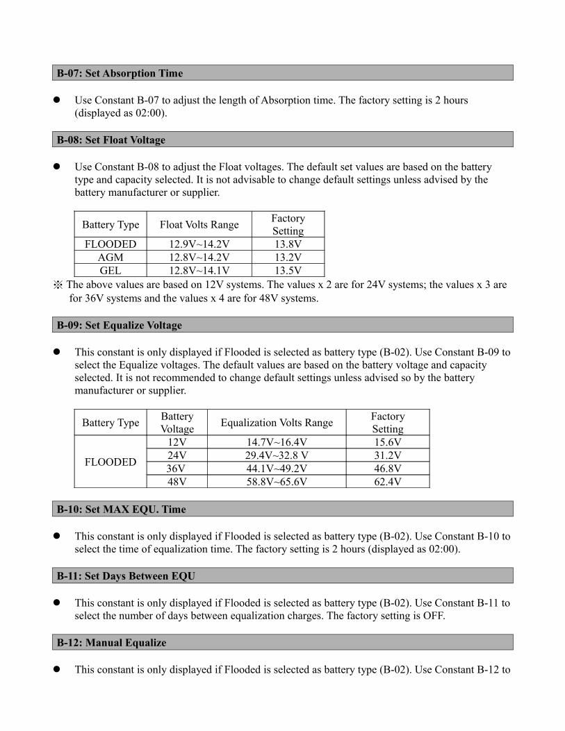
B-08: Set Float Voltage
Use Constant B-08 to adjust the Float voltages. The default set values are based on the battery type and capacity selected. It is not advisable to change default settings unless advised by the battery manufacturer or supplier.
Battery Type Float Volts Range FactorySetting
FLOODED 12.9V~14.2V 13.8VAGM 12.8V~14.2V 13.2VGEL 12.8V~14.1V 13.5V
※ The above values are based on 12V systems. The values x 2 are for 24V systems; the values x 3 are for 36V systems and the values x 4 are for 48V systems.
B-09: Set Equalize Voltage
This constant is only displayed if Flooded is selected as battery type (B-02). Use Constant B-09 to select the Equalize voltages. The default values are based on the battery voltage and capacity selected. It is not recommended to change default settings unless advised so by the battery manufacturer or supplier.
Battery Type Battery Voltage Equalization Volts Range Factory
Setting
FLOODED
12V 14.7V~16.4V 15.6V24V 29.4V~32.8 V 31.2V36V 44.1V~49.2V 46.8V48V 58.8V~65.6V 62.4V
B-10: Set MAX EQU. Time
This constant is only displayed if Flooded is selected as battery type (B-02). Use Constant B-10 to select the time of equalization time. The factory setting is 2 hours (displayed as 02:00).
B-11: Set Days Between EQU
This constant is only displayed if Flooded is selected as battery type (B-02). Use Constant B-11 to select the number of days between equalization charges. The factory setting is OFF.
B-12: Manual Equalize
This constant is only displayed if Flooded is selected as battery type (B-02). Use Constant B-12 to
choose between manual and automatic equalization settings. Press ENTER key to select Yes for manual equalization and then it will display the Equalize
voltage set in B-09 and the Max. EQU time set in B-10. Press ENTER key again to start the manual equalization.
※ During equalization, only ESC key is active to leave the equalization process screen.
After the manual equalization starts, BAT displays Battery voltage. Battery temperature and Equalizing will alternately blink. CHARGE displays charging current. Finally, the remaining time for equalization charge is counted down.
WARNING: Before the manual equalization is selected, AIMS MPPT+ should be connected to Battery Temperature Sensor (BTS-3). If it is not connected to BTS-3, “Warning, Bat. Sr Not Connected” is displayed.
Press ESC key to select No to return to the display of Group B.
Group CMPPT Setup
C-01: Set MPPT Type
Use Constant C-01 to set up the MPPT type: P and O, Scan and Hold, Percentage, Hold Input V. The factory setting is P and O.
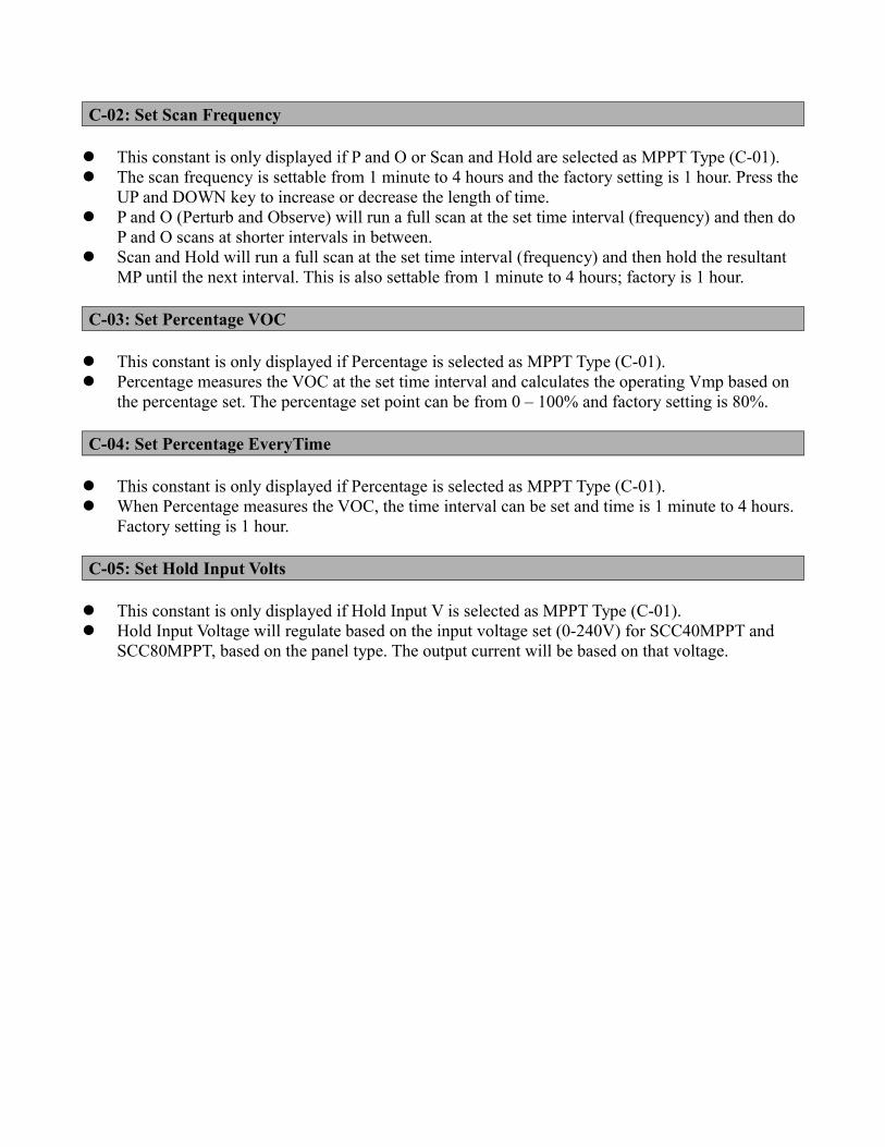
C-02: Set Scan Frequency
This constant is only displayed if P and O or Scan and Hold are selected as MPPT Type (C-01). The scan frequency is settable from 1 minute to 4 hours and the factory setting is 1 hour. Press the
UP and DOWN key to increase or decrease the length of time. P and O (Perturb and Observe) will run a full scan at the set time interval (frequency) and then do
P and O scans at shorter intervals in between. Scan and Hold will run a full scan at the set time interval (frequency) and then hold the resultant
MP until the next interval. This is also settable from 1 minute to 4 hours; factory is 1 hour.
C-03: Set Percentage VOC
This constant is only displayed if Percentage is selected as MPPT Type (C-01). Percentage measures the VOC at the set time interval and calculates the operating Vmp based on
the percentage set. The percentage set point can be from 0 – 100% and factory setting is 80%.
C-04: Set Percentage EveryTime
This constant is only displayed if Percentage is selected as MPPT Type (C-01). When Percentage measures the VOC, the time interval can be set and time is 1 minute to 4 hours.
Factory setting is 1 hour.
C-05: Set Hold Input Volts
This constant is only displayed if Hold Input V is selected as MPPT Type (C-01). Hold Input Voltage will regulate based on the input voltage set (0-240V) for SCC40MPPT and
SCC80MPPT, based on the panel type. The output current will be based on that voltage.
Group DAuxiliary Relay 1
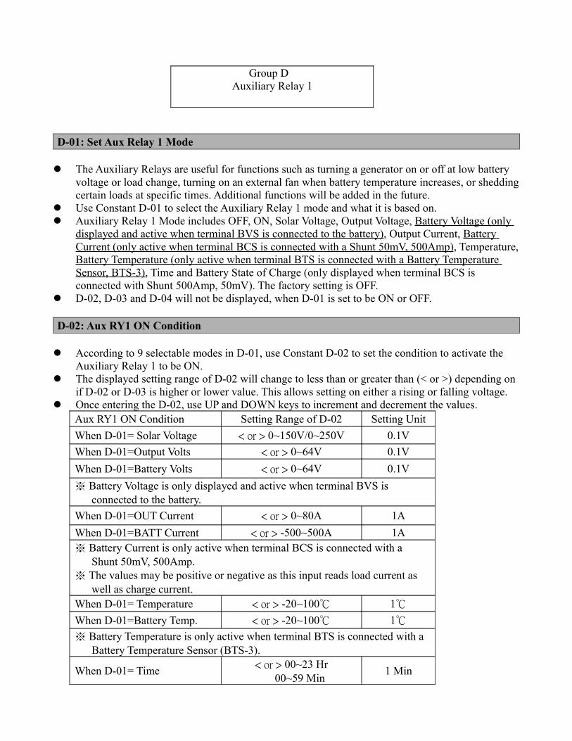
D-01: Set Aux Relay 1 Mode
The Auxiliary Relays are useful for functions such as turning a generator on or off at low battery voltage or load change, turning on an external fan when battery temperature increases, or shedding certain loads at specific times. Additional functions will be added in the future.
Use Constant D-01 to select the Auxiliary Relay 1 mode and what it is based on. Auxiliary Relay 1 Mode includes OFF, ON, Solar Voltage, Output Voltage, Battery Voltage (only
displayed and active when terminal BVS is connected to the battery), Output Current, Battery Current (only active when terminal BCS is connected with a Shunt 50mV, 500Amp), Temperature, Battery Temperature (only active when terminal BTS is connected with a Battery Temperature Sensor, BTS-3), Time and Battery State of Charge (only displayed when terminal BCS is connected with Shunt 500Amp, 50mV). The factory setting is OFF.
D-02, D-03 and D-04 will not be displayed, when D-01 is set to be ON or OFF.
D-02: Aux RY1 ON Condition
According to 9 selectable modes in D-01, use Constant D-02 to set the condition to activate the Auxiliary Relay 1 to be ON.
The displayed setting range of D-02 will change to less than or greater than (< or >) depending on if D-02 or D-03 is higher or lower value. This allows setting on either a rising or falling voltage.
Once entering the D-02, use UP and DOWN keys to increment and decrement the values. Aux RY1 ON Condition Setting Range of D-02 Setting UnitWhen D-01= Solar Voltage < or > 0~150V/0~250V 0.1VWhen D-01=Output Volts < or > 0~64V 0.1VWhen D-01=Battery Volts < or > 0~64V 0.1V※ Battery Voltage is only displayed and active when terminal BVS is
connected to the battery.When D-01=OUT Current < or > 0~80A 1AWhen D-01=BATT Current < or > -500~500A 1A※ Battery Current is only active when terminal BCS is connected with a
Shunt 50mV, 500Amp.※ The values may be positive or negative as this input reads load current as
well as charge current. When D-01= Temperature < or > -20~100℃ 1℃
When D-01=Battery Temp. < or > -20~100℃ 1℃
※ Battery Temperature is only active when terminal BTS is connected with a Battery Temperature Sensor (BTS-3).
When D-01= Time < or > 00~23 Hr 00~59 Min 1 Min
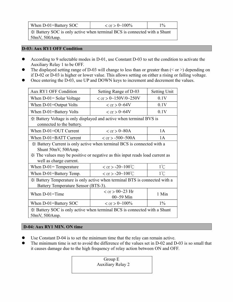
When D-01=Battery SOC < or > 0~100% 1%※ Battery SOC is only active when terminal BCS is connected with a Shunt 50mV, 500Amp.
D-03: Aux RY1 OFF Condition
According to 9 selectable modes in D-01, use Constant D-03 to set the condition to activate the Auxiliary Relay 1 to be OFF.
The displayed setting range of D-03 will change to less than or greater than (< or >) depending on if D-02 or D-03 is higher or lower value. This allows setting on either a rising or falling voltage.
Once entering the D-03, use UP and DOWN keys to increment and decrement the values.
Aux RY1 OFF Condition Setting Range of D-03 Setting UnitWhen D-01= Solar Voltage < or > 0~150V/0~250V 0.1VWhen D-01=Output Volts < or > 0~64V 0.1VWhen D-01=Battery Volts < or > 0~64V 0.1V※ Battery Voltage is only displayed and active when terminal BVS is
connected to the battery.When D-01=OUT Current < or > 0~80A 1AWhen D-01=BATT Current < or > -500~500A 1A ※ Battery Current is only active when terminal BCS is connected with a
Shunt 50mV, 500Amp.※ The values may be positive or negative as this input reads load current as
well as charge current.When D-01= Temperature < or > -20~100℃ 1℃
When D-01=Battery Temp. < or > -20~100℃ 1℃
※ Battery Temperature is only active when terminal BTS is connected with a Battery Temperature Sensor (BTS-3).
When D-01=Time < or > 00~23 Hr 00~59 Min 1 Min
When D-01=Battery SOC < or > 0~100% 1%※ Battery SOC is only active when terminal BCS is connected with a Shunt 50mV, 500Amp.
D-04: Aux RY1 MIN. ON time
Use Constant D-04 is to set the minimum time that the relay can remain active. The minimum time is set to avoid the difference of the values set in D-02 and D-03 is so small that
it causes damage due to the high frequency of relay action between ON and OFF.
Group EAuxiliary Relay 2
E-01: Set Aux Relay 2 ModeE-02: Aux RY2 ON ConditionE-03: Aux RY2 OFF ConditionE-04: Aux RY2 MIN. ON time
※ The functions and the settings of Auxiliary Relay 2 are exactly the same as those of Auxiliary Relay 1 so please refer to above Group D, Auxiliary Relay 1 description.
Group FParallel Setup
F-01: Parallel MODE
Use Constant F-01 to set up AIMS MPPT+ Network. Each AIMS MPPT+ in parallel requires a mode and address entry.
The Mode choices are:
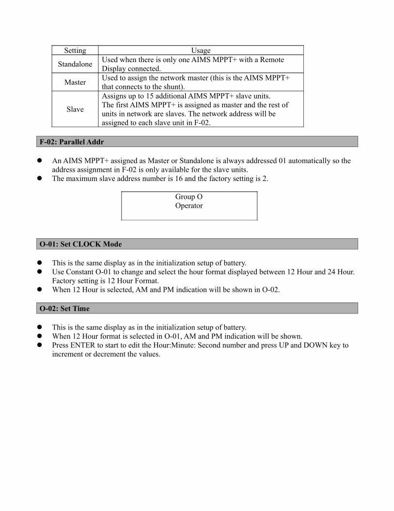
Setting Usage
Standalone Used when there is only one AIMS MPPT+ with a Remote Display connected.
Master Used to assign the network master (this is the AIMS MPPT+ that connects to the shunt).
Slave
Assigns up to 15 additional AIMS MPPT+ slave units.The first AIMS MPPT+ is assigned as master and the rest of units in network are slaves. The network address will be assigned to each slave unit in F-02.
F-02: Parallel Addr
An AIMS MPPT+ assigned as Master or Standalone is always addressed 01 automatically so the address assignment in F-02 is only available for the slave units.
The maximum slave address number is 16 and the factory setting is 2.
Group OOperator
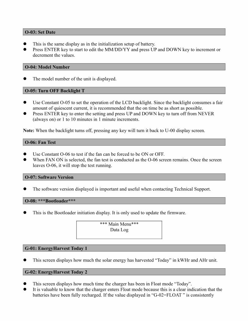
O-01: Set CLOCK Mode
This is the same display as in the initialization setup of battery. Use Constant O-01 to change and select the hour format displayed between 12 Hour and 24 Hour.
Factory setting is 12 Hour Format. When 12 Hour is selected, AM and PM indication will be shown in O-02.
O-02: Set Time
This is the same display as in the initialization setup of battery. When 12 Hour format is selected in O-01, AM and PM indication will be shown. Press ENTER to start to edit the Hour:Minute: Second number and press UP and DOWN key to
increment or decrement the values.
O-03: Set Date
This is the same display as in the initialization setup of battery. Press ENTER key to start to edit the MM/DD/YY and press UP and DOWN key to increment or
decrement the values.
O-04: Model Number
The model number of the unit is displayed.
O-05: Turn OFF Backlight T Use Constant O-05 to set the operation of the LCD backlight. Since the backlight consumes a fair
amount of quiescent current, it is recommended that the on time be as short as possible. Press ENTER key to enter the setting and press UP and DOWN key to turn off from NEVER
(always on) or 1 to 10 minutes in 1 minute increments.
Note: When the backlight turns off, pressing any key will turn it back to U-00 display screen.
O-06: Fan Test
Use Constant O-06 to test if the fan can be forced to be ON or OFF. When FAN ON is selected, the fan test is conducted as the O-06 screen remains. Once the screen
leaves O-06, it will stop the test running.
O-07: Software Version
The software version displayed is important and useful when contacting Technical Support.
O-08: ***Bootloader***
This is the Bootloader initiation display. It is only used to update the firmware.
*** Main Menu***Data Log
G-01: EnergyHarvest Today 1
This screen displays how much the solar energy has harvested “Today” in kWHr and AHr unit.
G-02: EnergyHarvest Today 2
This screen displays how much time the charger has been in Float mode “Today”. It is valuable to know that the charger enters Float mode because this is a clear indication that the
batteries have been fully recharged. If the value displayed in “G-02=FLOAT ” is consistently
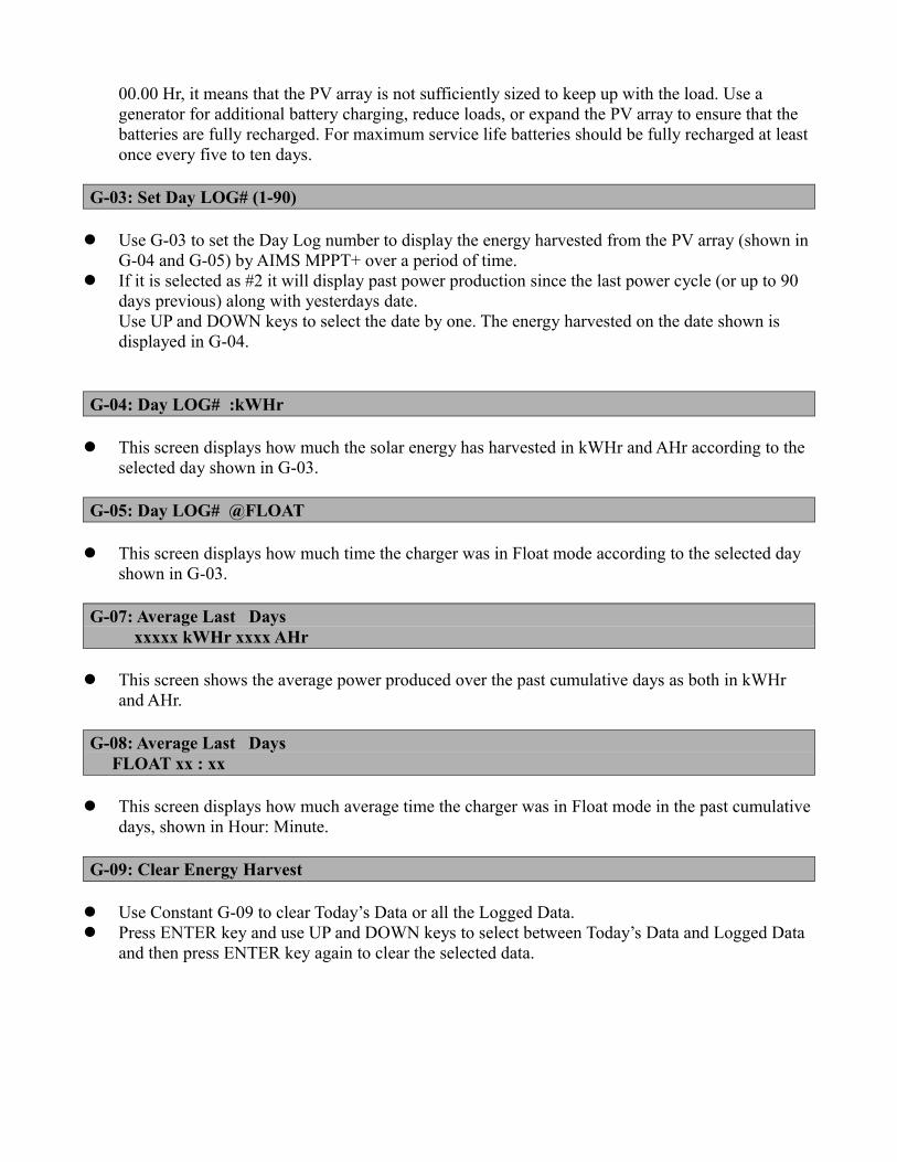
00.00 Hr, it means that the PV array is not sufficiently sized to keep up with the load. Use a generator for additional battery charging, reduce loads, or expand the PV array to ensure that the batteries are fully recharged. For maximum service life batteries should be fully recharged at least once every five to ten days.
G-03: Set Day LOG# (1-90)
Use G-03 to set the Day Log number to display the energy harvested from the PV array (shown in G-04 and G-05) by AIMS MPPT+ over a period of time.
If it is selected as #2 it will display past power production since the last power cycle (or up to 90 days previous) along with yesterdays date.Use UP and DOWN keys to select the date by one. The energy harvested on the date shown is displayed in G-04.
G-04: Day LOG# :kWHr
This screen displays how much the solar energy has harvested in kWHr and AHr according to the selected day shown in G-03.
G-05: Day LOG# @FLOAT
This screen displays how much time the charger was in Float mode according to the selected day shown in G-03.
G-07: Average Last Daysxxxxx kWHr xxxx AHr
This screen shows the average power produced over the past cumulative days as both in kWHr and AHr.
G-08: Average Last Days FLOAT xx : xx
This screen displays how much average time the charger was in Float mode in the past cumulative days, shown in Hour: Minute.
G-09: Clear Energy Harvest
Use Constant G-09 to clear Today’s Data or all the Logged Data. Press ENTER key and use UP and DOWN keys to select between Today’s Data and Logged Data
and then press ENTER key again to clear the selected data.
Chapter 6 Trouble Shooting
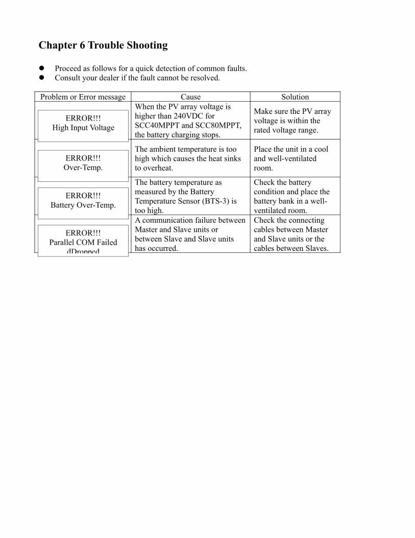
Proceed as follows for a quick detection of common faults. Consult your dealer if the fault cannot be resolved.
Problem or Error message Cause SolutionWhen the PV array voltage is higher than 240VDC for SCC40MPPT and SCC80MPPT, the battery charging stops.
Make sure the PV array voltage is within the rated voltage range.
The ambient temperature is too high which causes the heat sinks to overheat.
Place the unit in a cool and well-ventilated room.
The battery temperature as measured by the Battery Temperature Sensor (BTS-3) is too high.
Check the battery condition and place the battery bank in a well-ventilated room.
A communication failure between Master and Slave units or between Slave and Slave units has occurred.
Check the connecting cables between Master and Slave units or the cables between Slaves.
ERROR!!!High Input Voltage
ERROR!!!Over-Temp.
ERROR!!!Parallel COM Failed
dDropped
ERROR!!!Battery Over-Temp.

Contact Us
9736 S. Virginia St. STE A, Reno, NV 89511
Tel: (775) 359-6703
Fax: (775) 359-6753
e-mail:[email protected]

AIMS Operating Corp., Inc. dba AIMS Power Warranty Instructions:
This product is designed using the most modern digital technology and under very strict quality control and testing guide lines. If however you feel this product is not performing as it should, please contact us:
[email protected] or (775)359-6703
We will do our best to resolve your concerns. If the product needs repair or replacement, make sure to keep your receipt/invoice, as that will need to be sent back along with the package and RA# prepaid to AIMS. You have a full 1 year from date of purchase warranty.
This warranty is valid world wide with the exception that freight and duty charges incurred outside the contiguous 48 United States will be prepaid by customer.
Except as provided above, AIMS makes no warranty of any kind, express or implied, including without limitation the implied warranties of merchantability and fitness for a particular purpose. In no event shall AIMS be liable for indirect, special or consequential damages. This warranty only applies to AIMS Power branded products. All other name brand products are warranted by and according to their respective manufacturer. Please do not attempt to return non-AIMS Power branded products to AIMS Power.
For additional products such as:- Modified sine wave inverters- Pure sine wave inverters- Solar Charge Controllers- On Grid Inverters- Inverter Chargers and Automatic transfer switches- Custom cut cables- Batteries- Solar Panels
Please visit our web site: www.aimscorp.net
To find out where to buy any of our products, you may also e-mail: [email protected] or call (775)359-6703.