Embed Size (px)
Citation preview
HEADQUARTERSDEPARTMENT OF THE ARMY
FM 3-01.11 (FM 44-100-2)
AIR DEFENSE ARTILLERYREFERENCE HANDBOOK
DISTRIBUTION RESTRICTION: Approved for public release; distribution is unlimited.
i
∗∗∗∗ FM 3-01.11 (FM 44-1-2)
Field ManualNo. 3-01.11
HeadquartersDepartment of the Army
Washington, DC, 31 OCTOBER 2000
Air Defense ArtilleryReference Handbook
ContentsPage
Preface ........................................................................................................................ iii
Chapter 1 AIR DEFENSE ARTILLERY MISSION .....................................................................1-1Mission .......................................................................................................................1-1Air and Missile Defense in Relation to Army Tenets .................................................1-2Air and Missile Defense in Force Protection..............................................................1-3Air Defense Battlefield Operating System .................................................................1-3
Chapter 2 THREAT.....................................................................................................................2-1The Evolving Threat...................................................................................................2-1Electronic Warfare .....................................................................................................2-8Weapons of Mass Destruction...................................................................................2-9Summary....................................................................................................................2-9
Chapter 3 SHORT RANGE AIR DEFENSE ...............................................................................3-1MANPADS Stinger.....................................................................................................3-1Bradley Stinger Fighting Vehicle................................................................................3-8Linebacker System ..................................................................................................3-11Avenger System.......................................................................................................3-14
Chapter 4 THEATER HIGH ALTITUDE AREA DEFENSE SYSTEM ........................................4-1Mission .......................................................................................................................4-1System Description ....................................................................................................4-1
∗ This publication supersedes FM 44-1-2, 15 June 1984
Distribution Restriction: Approved for public release; distribution is unlimited.
FM 44-100-2
ii
System Operational Overview................................................................................. 4-10
Chapter 5 PATRIOT AIR DEFENSE SYSTEM ......................................................................... 5-1Mission ...................................................................................................................... 5-1System Description – Battalion Fire Direction Center ............................................... 5-1System Description - Firing Battery........................................................................... 5-3System Operational Overview................................................................................... 5-9Patriot Logistics Support ......................................................................................... 5-16
Chapter 6 COMMAND AND CONTROL SYSTEMS ................................................................. 6-1Air and Missile Defense Battle Command Organizations ......................................... 6-1Air and Missile Defense Planning and Control System............................................. 6-2Tactical Command System ....................................................................................... 6-6Master Information and Coordination Central ........................................................... 6-6Forward Area Air Defense C3I System ..................................................................... 6-6
Chapter 7 TRAINING DEVICES AND AERIAL TARGETS....................................................... 7-1MANPADS Stinger Training Devices ........................................................................ 7-1Bradley Stinger Fighting Vehicle/Linebacker Training Devices ................................ 7-4Avenger Training Devices ......................................................................................... 7-6Sentinel Training Devices.......................................................................................... 7-7FAAD C3I Training Devices ...................................................................................... 7-7Patriot Training Devices ............................................................................................ 7-8THAAD Training Devices ........................................................................................ 7-11Joint Radio Operator and Maintenance Procedures Simulator............................... 7-13Aerial Targets for Training....................................................................................... 7-14
Appendix A ADA EMPLOYMENT PRINCIPLES, GUIDELINES, AND PRIORITIES ..................A-1
Appendix B ADA SYMBOLS ........................................................................................................B-1
GLOSSARY ..................................................................................................Glossary-1
BIBLIOGRAPHY ..................................................................................... Bibliography-1
INDEX ................................................................................................................ Index-1
III
PrefaceThe purpose of this field manual (FM) is to familiarize personnel with ADA operations and weaponsystems. This FM will be useful to personnel serving in the following types of positions:
• staff positions requiring general knowledge of Air Defense Artillery systems andoperations
• instructor positions in service schools and the Reserve Officer Training Corps (ROTC)• members of advisory elements and groups assigned to missions in foreign countries• advisory positions in reserve component forces• command and leadership positions in special operations force units• executive positions and advisory positions that require knowledge of air defense
subjectsReaders are reminded that weapons systems and operations are continually changing. Publicationssuch as technical manuals, tables of organization and equipment, and mission training plans(MTP) provide more detailed information on specific subjects. Many of these sources are referred toin appropriate sections of this field manual.The proponent for this manual is HQ TRADOC. Send comments and recommendations onDA Form 2028 to Commandant, USAADASCH, ATTN: ATSA-DT-WF, Fort Bliss, TX 79916-3802.
Unless this publication states otherwise, masculine nouns and pronouns do not refer exclusively tomen.
iii
1-1
Chapter 1
Air Defense Artillery MissionThis chapter addresses the Air Defense Artillery (ADA) mission and therelationship to the Army tenets and battlefield operating systems. ADAcontributes unique capabilities to theater counterair and theater missiledefense operations as part of a joint, multinational, or interagency team.The theater objectives of ADA are to preserve combat power, gain theinitiative, and support offensive operations.
MISSION1-1. The mission of US Army Air Defense Artillery is to protect the force andselected geopolitical assets from aerial attack, missile attack andsurveillance.
FORCES1-2. ADA commanders allocate active and reserve component ADA assetsbased on the supported commander's priorities. In addition, the mission isbroadly written to include protection of critical assets, installations, andfacilities along with joint and multinational forces when required.
GEOPOLITICAL ASSETS1-3. Geopolitical assets are nonmilitary assets that US, allied, or host nationcivil authorities nominate for air and missile defense protection. These assetscould be political, religious, ethnic, historical, or territorial in nature. Sinceprotection of geopolitical assets may not directly support military operations,integration of geopolitical assets into the air and missile defense prioritieslist must be done at the highest levels. Geopolitical assets may include USterritories.
THREAT1-4. The threat includes all aircraft, aerial surveillance platforms, andtheater missiles. Chapter 2 provides more detail and information on thethreat.
CONSEQUENCES1-5. Successful air and missile defense is key to generating and sustainingcombat power in force projection operations. The AD contribution to friendlyefforts to counter threat reconnaissance, intelligence surveillance, and targetacquisition efforts has gained greater emphasis. Current and future ArmyADA capabilities, both active and reserve component, must synergisticallycombine with the AD assets of other services to defeat the multifacetedthreat. Army ADA forces participate in operations at all levels of war.
FM 44-100-2
1-2
AIR AND MISSILE DEFENSE IN RELATION TO ARMY TENETS1-6. Air and missile defense operations are inherently joint operations, multi-component, and embody Army doctrine. ADA forces are versatile, agile, andfight throughout the depth of the battlefield. Through aggressive planningand fully orchestrated execution, ADA allows the commander at any level toseize and maintain the initiative. Commanders integrate air and missiledefense operations into campaigns fought at the operational level, and battlesand engagements fought at the tactical level.
INITIATIVE1-7. Air Defense Artillery units participate in planning for offensive anddefensive counterair and theater missile defense operations. Air and missiledefense commanders recommend enemy airfields, missile launch sites,command and control nodes, and logistics for deep attack. They contribute towinning the information war by destroying threat aerial reconnaissanceplatforms. ADA units engage air threats from directions and in ways that theenemy does not expect.
AGILITY1-8. ADA units anticipate and counter enemy actions and react rapidly tochanges in the situation. Agility is as much a mental quality as a physicalone. ADA must quickly change from offense to defense, entry to decisiveoperations, and counterair to theater missile defense. Concentrating coverageand fires, or screening the flanks from attack and surveillance, are tasksroutinely accomplished by ADA units.
DEPTH1-9. ADA units are among the first units to deploy during force-projectionoperations and the last units to depart during redeployment operations. Theyconduct operations throughout the width and depth of the theater. ADA unitsachieve defense in depth using a system of systems approach, which givesmultiple opportunities to defeat the aerial threat. ADA systems see deep intothreat airspace to contribute to the commander's situational awareness anddefeat air, missile, and surveillance threats at maximum range. Depth alsoincludes staying power, which is the access to adequate resources to continuethe fight. Army air and missile defense includes contributions from allbattlefield operating systems and units.
SYNCHRONIZATION1-10. The Synchronization tenet requires controlling the tempo of operationsas well as weighting and shifting air and missile defense efforts. ADA unitscounter the entire aerial threat spectrum by integrating a system of systems.Commanders integrate their operations horizontally with all battlefieldoperating systems and vertically with both higher and lower ADA units.
VERSATILITY1-11. ADA units meet diverse mission requirements. They require discipline,high standards, and thorough preparation. Commanders need to shift focus,task-organize, and move from one role or mission to another quickly and
FM 44-100-2
1-3
efficiently. ADA units are multifunctional, able to defeat several different airthreats while operating at the strategic, operational, and tactical levels.
AIR AND MISSILE DEFENSE IN FORCE PROTECTION1-12. Commanders seek to apply overwhelming combat power to achievevictory with minimum casualties to their forces and assets. Combat powercombines the elements of maneuver, firepower, protection, and leadership.Overwhelming combat power is the ability to focus sufficient force to ensuresuccess and deny the threat any chance of escape or effective retaliation.Commanders apply overwhelming combat power by bringing all combatelements to bear at the optimum time and place, giving the threat noopportunity to respond effectively. Commanders integrate and coordinate avariety of functions with the elements of combat power. As a result, theyconvert the potential of forces, resources, and opportunities into actualcapability through violent, coordinated action at the decisive time and place.They attempt to defeat the threat's combat power by interfering with itsability to conduct reconnaissance, maneuver, and apply firepower.1-13. Air and missile defense makes its greatest contribution to forceprotection, while contributing to all four elements of combat power.Protection conserves the fighting potential of a force so commanders canapply it at the decisive time and place. Protection includes the active andpassive actions units take to preserve combat power and deny the enemy theability to successfully attack the force.1-14. Air and missile defense operations are important active force protectionmeasures. Offensive counterair and TMD attack operations attempt to defeator suppress threat capabilities to launch air and missile attacks. Defensivecounterair and TMD active defense destroy enemy aircraft and missiles thatthreaten the force.
AIR DEFENSE BATTLEFIELD OPERATING SYSTEM1-15. Air defense is one of the seven battlefield operating systems thatprovide a structure for integrating and synchronizing critical combatactivities in time, space, and purpose. At every echelon, commanders use theavailable battle command system to visualize, plan, direct, coordinate, adjust,and control the battlefield operating systems. The seven battlefield operatingsystems are:
• Intelligence• Maneuver• Fire support• Air defense• Mobility/Countermobility/Survivability• Combat Service Support• Command and Control
1-16. Battlefield operating systems exist at all echelons of command.Successful operations occur when the battlefield operating systems interacthorizontally and vertically. Horizontal interaction occurs when all battlefieldoperating systems interact at the same echelon to maximize combat power.

FM 44-100-2
1-4
Vertical integration occurs when higher and lower echelons within eachbattlefield operating system interact to synchronize operations. Air andmissile defense commanders synchronize their operations by integratingthem horizontally with other battlefield operating systems and verticallywithin the Air Defense battlefield operating system.
2-1
Chapter 2
ThreatThis chapter describes the air and missile threats facing U.S. militaryforces. This evolving threat will take on new, stressing characteristicsduring the 21st century. Adversaries will closely observe emerging U.S.capabilities in an effort to identify and exploit weaknesses usingasymmetric approaches. An asymmetric approach seeks to negate U.S.capabilities by simple counters and avoids a direct match with U.S.strengths. Fundamental capabilities that 21st-century adversaries maypursue to counter U.S. strengths include weapons of mass destruction(WMD); unmanned reconnaissance, surveillance, and target acquisition(RSTA) systems; precision strike weapons; large numbers of inexpensiverockets; land attack cruise missiles (LACM); and information warfare.Some states will rely on asymmetric capabilities as a substitute for, orcomplement to, large conventional forces. This trend started in the late1980s, and is continuing today. The proliferation of low-cost, high-payoff,unmanned systems, theater missiles (TM), unmanned aerial vehicles(UAV), and large caliber rockets (LCR) is a recent trend.
THE EVOLVING THREAT2-1. Fixed-wing aircraft and helicopters are still formidable threats, however,the trend is toward the proliferation of unmanned systems: ballistic missiles,cruise missiles (CM), unmanned aerial vehicles (UAV), and rockets. Thetrend toward unmanned threats is driven by cost, training, operationalfactors and a strategy to counter, rather than match, enemy capabilities.Potential adversaries can obtain a significant number of UAV or CM for theprice of one or two highly sophisticated aircraft, without the attendant costsof training, maintaining, basing, and sustaining a manned aircraft fleet.These weapons possess inherently lethal capabilities that stress the defenseof the force, and they are increasingly available on the world market.Sophisticated and rudimentary versions of these unmanned systems pose adanger to deployed U.S. military forces. TBMs and CMs can deliver WMD ondeployed forces or geopolitical assets. RSTA UAVs can detect U.S. forceoperations and provide the basis for near real time targeting, leading topotential disruption of decisive operations. Rockets, such as large-calibermultiple rocket launchers (MRL), pose special hazards and challenges acrossthe spectrum of operations. Traditional air threats will still exist in the worldof tomorrow. Helicopters continue to pose a significant lethal hazard forground forces. Fixed-wing aircraft continue to evolve as expensive but highlycapable weapon systems.
FM 44-100-2
2-2
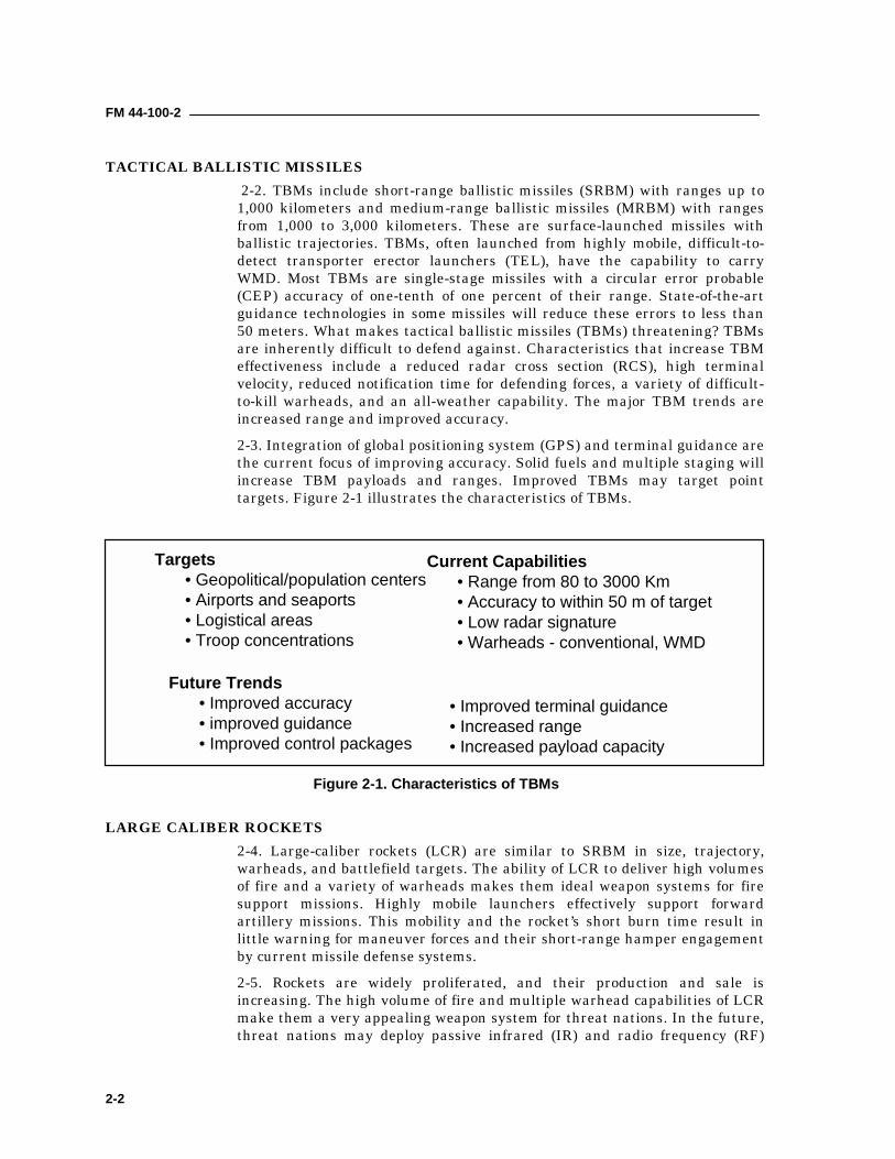
TACTICAL BALLISTIC MISSILES 2-2. TBMs include short-range ballistic missiles (SRBM) with ranges up to1,000 kilometers and medium-range ballistic missiles (MRBM) with rangesfrom 1,000 to 3,000 kilometers. These are surface-launched missiles withballistic trajectories. TBMs, often launched from highly mobile, difficult-to-detect transporter erector launchers (TEL), have the capability to carryWMD. Most TBMs are single-stage missiles with a circular error probable(CEP) accuracy of one-tenth of one percent of their range. State-of-the-artguidance technologies in some missiles will reduce these errors to less than50 meters. What makes tactical ballistic missiles (TBMs) threatening? TBMsare inherently difficult to defend against. Characteristics that increase TBMeffectiveness include a reduced radar cross section (RCS), high terminalvelocity, reduced notification time for defending forces, a variety of difficult-to-kill warheads, and an all-weather capability. The major TBM trends areincreased range and improved accuracy.2-3. Integration of global positioning system (GPS) and terminal guidance arethe current focus of improving accuracy. Solid fuels and multiple staging willincrease TBM payloads and ranges. Improved TBMs may target pointtargets. Figure 2-1 illustrates the characteristics of TBMs.
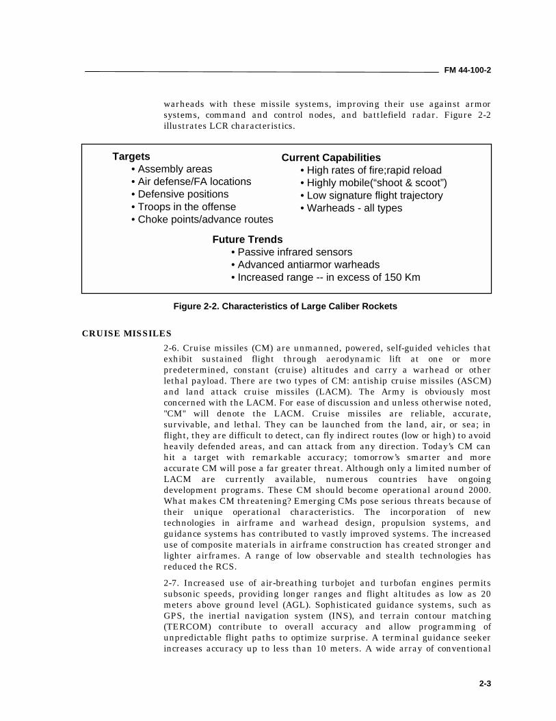
LARGE CALIBER ROCKETS2-4. Large-caliber rockets (LCR) are similar to SRBM in size, trajectory,warheads, and battlefield targets. The ability of LCR to deliver high volumesof fire and a variety of warheads makes them ideal weapon systems for firesupport missions. Highly mobile launchers effectively support forwardartillery missions. This mobility and the rocket’s short burn time result inlittle warning for maneuver forces and their short-range hamper engagementby current missile defense systems.2-5. Rockets are widely proliferated, and their production and sale isincreasing. The high volume of fire and multiple warhead capabilities of LCRmake them a very appealing weapon system for threat nations. In the future,threat nations may deploy passive infrared (IR) and radio frequency (RF)
Targets• Geopolitical/population centers• Airports and seaports• Logistical areas• Troop concentrations
Current Capabilities• Range from 80 to 3000 Km• Accuracy to within 50 m of target• Low radar signature• Warheads - conventional, WMD
Future Trends• Improved accuracy• improved guidance• Improved control packages
• Improved terminal guidance• Increased range• Increased payload capacity
Figure 2-1. Characteristics of TBMs
FM 44-100-2
2-3
warheads with these missile systems, improving their use against armorsystems, command and control nodes, and battlefield radar. Figure 2-2illustrates LCR characteristics.
CRUISE MISSILES2-6. Cruise missiles (CM) are unmanned, powered, self-guided vehicles thatexhibit sustained flight through aerodynamic lift at one or morepredetermined, constant (cruise) altitudes and carry a warhead or otherlethal payload. There are two types of CM: antiship cruise missiles (ASCM)and land attack cruise missiles (LACM). The Army is obviously mostconcerned with the LACM. For ease of discussion and unless otherwise noted,"CM" will denote the LACM. Cruise missiles are reliable, accurate,survivable, and lethal. They can be launched from the land, air, or sea; inflight, they are difficult to detect, can fly indirect routes (low or high) to avoidheavily defended areas, and can attack from any direction. Today’s CM canhit a target with remarkable accuracy; tomorrow’s smarter and moreaccurate CM will pose a far greater threat. Although only a limited number ofLACM are currently available, numerous countries have ongoingdevelopment programs. These CM should become operational around 2000.What makes CM threatening? Emerging CMs pose serious threats because oftheir unique operational characteristics. The incorporation of newtechnologies in airframe and warhead design, propulsion systems, andguidance systems has contributed to vastly improved systems. The increaseduse of composite materials in airframe construction has created stronger andlighter airframes. A range of low observable and stealth technologies hasreduced the RCS.2-7. Increased use of air-breathing turbojet and turbofan engines permitssubsonic speeds, providing longer ranges and flight altitudes as low as 20meters above ground level (AGL). Sophisticated guidance systems, such asGPS, the inertial navigation system (INS), and terrain contour matching(TERCOM) contribute to overall accuracy and allow programming ofunpredictable flight paths to optimize surprise. A terminal guidance seekerincreases accuracy up to less than 10 meters. A wide array of conventional
Targets• Assembly areas• Air defense/FA locations• Defensive positions• Troops in the offense• Choke points/advance routes
Current Capabilities• High rates of fire;rapid reload• Highly mobile(“shoot & scoot”)• Low signature flight trajectory• Warheads - all types
Future Trends• Passive infrared sensors• Advanced antiarmor warheads• Increased range -- in excess of 150 Km
Figure 2-2. Characteristics of Large Caliber Rockets
FM 44-100-2
2-4
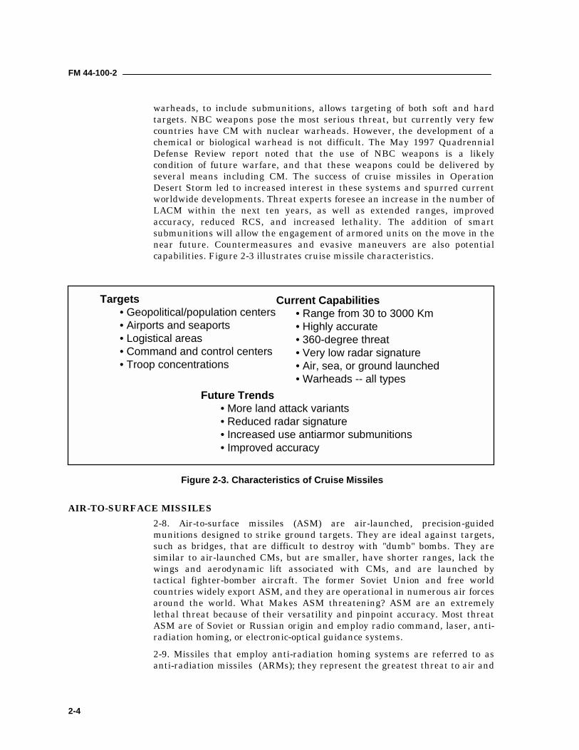
warheads, to include submunitions, allows targeting of both soft and hardtargets. NBC weapons pose the most serious threat, but currently very fewcountries have CM with nuclear warheads. However, the development of achemical or biological warhead is not difficult. The May 1997 QuadrennialDefense Review report noted that the use of NBC weapons is a likelycondition of future warfare, and that these weapons could be delivered byseveral means including CM. The success of cruise missiles in OperationDesert Storm led to increased interest in these systems and spurred currentworldwide developments. Threat experts foresee an increase in the number ofLACM within the next ten years, as well as extended ranges, improvedaccuracy, reduced RCS, and increased lethality. The addition of smartsubmunitions will allow the engagement of armored units on the move in thenear future. Countermeasures and evasive maneuvers are also potentialcapabilities. Figure 2-3 illustrates cruise missile characteristics.
AIR-TO-SURFACE MISSILES2-8. Air-to-surface missiles (ASM) are air-launched, precision-guidedmunitions designed to strike ground targets. They are ideal against targets,such as bridges, that are difficult to destroy with "dumb" bombs. They aresimilar to air-launched CMs, but are smaller, have shorter ranges, lack thewings and aerodynamic lift associated with CMs, and are launched bytactical fighter-bomber aircraft. The former Soviet Union and free worldcountries widely export ASM, and they are operational in numerous air forcesaround the world. What Makes ASM threatening? ASM are an extremelylethal threat because of their versatility and pinpoint accuracy. Most threatASM are of Soviet or Russian origin and employ radio command, laser, anti-radiation homing, or electronic-optical guidance systems.2-9. Missiles that employ anti-radiation homing systems are referred to asanti-radiation missiles (ARMs); they represent the greatest threat to air and
Targets• Geopolitical/population centers• Airports and seaports• Logistical areas• Command and control centers• Troop concentrations
Current Capabilities• Range from 30 to 3000 Km• Highly accurate• 360-degree threat• Very low radar signature• Air, sea, or ground launched• Warheads -- all types
Future Trends• More land attack variants• Reduced radar signature• Increased use antiarmor submunitions• Improved accuracy
Figure 2-3. Characteristics of Cruise Missiles
FM 44-100-2
2-5
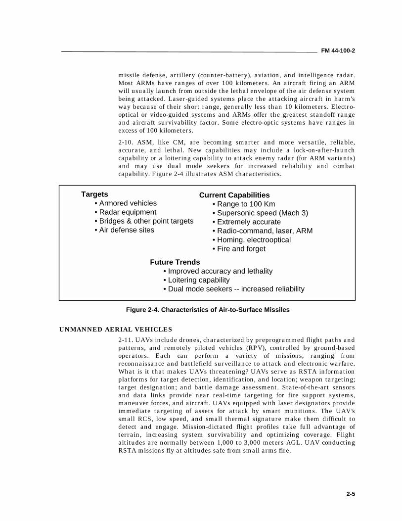
missile defense, artillery (counter-battery), aviation, and intelligence radar.Most ARMs have ranges of over 100 kilometers. An aircraft firing an ARMwill usually launch from outside the lethal envelope of the air defense systembeing attacked. Laser-guided systems place the attacking aircraft in harm'sway because of their short range, generally less than 10 kilometers. Electro-optical or video-guided systems and ARMs offer the greatest standoff rangeand aircraft survivability factor. Some electro-optic systems have ranges inexcess of 100 kilometers.2-10. ASM, like CM, are becoming smarter and more versatile, reliable,accurate, and lethal. New capabilities may include a lock-on-after-launchcapability or a loitering capability to attack enemy radar (for ARM variants)and may use dual mode seekers for increased reliability and combatcapability. Figure 2-4 illustrates ASM characteristics.
UNMANNED AERIAL VEHICLES2-11. UAVs include drones, characterized by preprogrammed flight paths andpatterns, and remotely piloted vehicles (RPV), controlled by ground-basedoperators. Each can perform a variety of missions, ranging fromreconnaissance and battlefield surveillance to attack and electronic warfare.What is it that makes UAVs threatening? UAVs serve as RSTA informationplatforms for target detection, identification, and location; weapon targeting;target designation; and battle damage assessment. State-of-the-art sensorsand data links provide near real-time targeting for fire support systems,maneuver forces, and aircraft. UAVs equipped with laser designators provideimmediate targeting of assets for attack by smart munitions. The UAV’ssmall RCS, low speed, and small thermal signature make them difficult todetect and engage. Mission-dictated flight profiles take full advantage ofterrain, increasing system survivability and optimizing coverage. Flightaltitudes are normally between 1,000 to 3,000 meters AGL. UAV conductingRSTA missions fly at altitudes safe from small arms fire.
Targets• Armored vehicles• Radar equipment• Bridges & other point targets• Air defense sites
Current Capabilities• Range to 100 Km• Supersonic speed (Mach 3)• Extremely accurate• Radio-command, laser, ARM• Homing, electrooptical• Fire and forget
Future Trends• Improved accuracy and lethality• Loitering capability• Dual mode seekers -- increased reliability
Figure 2-4. Characteristics of Air-to-Surface Missiles
FM 44-100-2
2-6
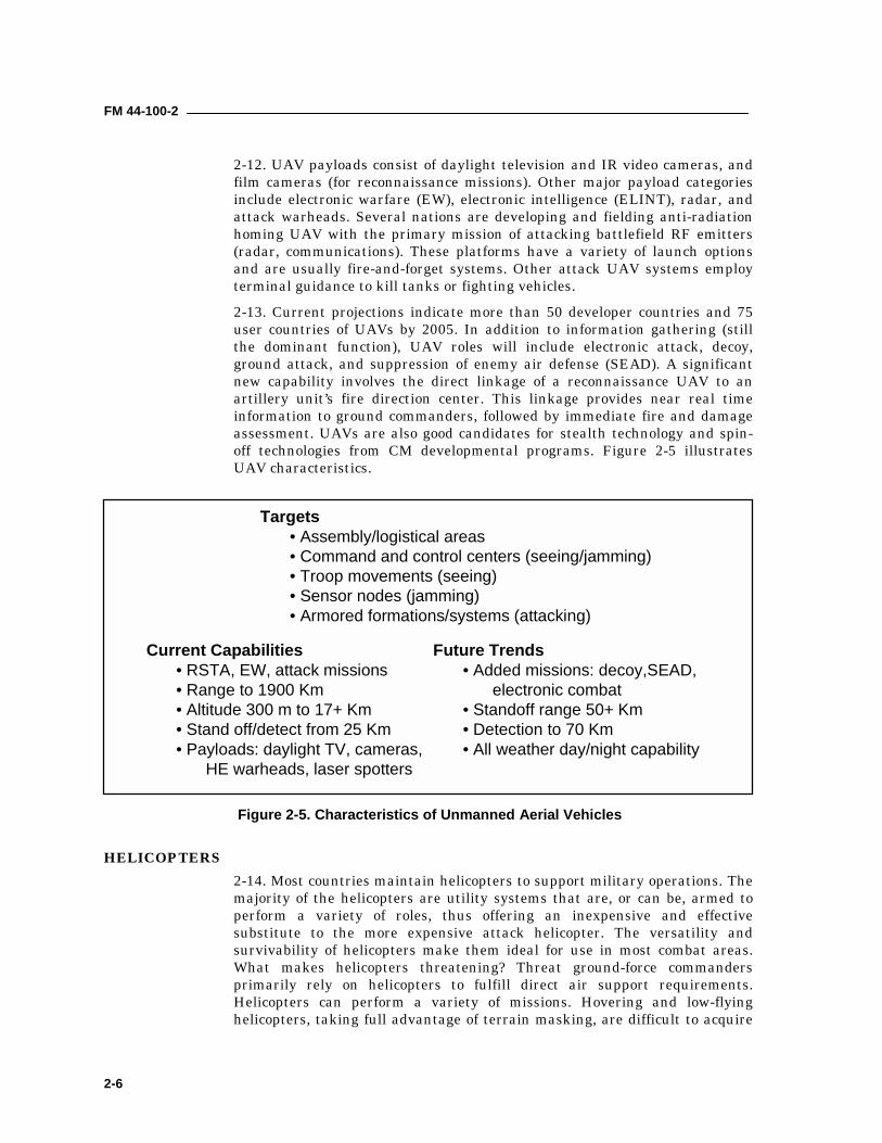
2-12. UAV payloads consist of daylight television and IR video cameras, andfilm cameras (for reconnaissance missions). Other major payload categoriesinclude electronic warfare (EW), electronic intelligence (ELINT), radar, andattack warheads. Several nations are developing and fielding anti-radiationhoming UAV with the primary mission of attacking battlefield RF emitters(radar, communications). These platforms have a variety of launch optionsand are usually fire-and-forget systems. Other attack UAV systems employterminal guidance to kill tanks or fighting vehicles.2-13. Current projections indicate more than 50 developer countries and 75user countries of UAVs by 2005. In addition to information gathering (stillthe dominant function), UAV roles will include electronic attack, decoy,ground attack, and suppression of enemy air defense (SEAD). A significantnew capability involves the direct linkage of a reconnaissance UAV to anartillery unit’s fire direction center. This linkage provides near real timeinformation to ground commanders, followed by immediate fire and damageassessment. UAVs are also good candidates for stealth technology and spin-off technologies from CM developmental programs. Figure 2-5 illustratesUAV characteristics.
HELICOPTERS2-14. Most countries maintain helicopters to support military operations. Themajority of the helicopters are utility systems that are, or can be, armed toperform a variety of roles, thus offering an inexpensive and effectivesubstitute to the more expensive attack helicopter. The versatility andsurvivability of helicopters make them ideal for use in most combat areas.What makes helicopters threatening? Threat ground-force commandersprimarily rely on helicopters to fulfill direct air support requirements.Helicopters can perform a variety of missions. Hovering and low-flyinghelicopters, taking full advantage of terrain masking, are difficult to acquire
Targets• Assembly/logistical areas• Command and control centers (seeing/jamming)• Troop movements (seeing)• Sensor nodes (jamming)• Armored formations/systems (attacking)
Current Capabilities• RSTA, EW, attack missions• Range to 1900 Km• Altitude 300 m to 17+ Km• Stand off/detect from 25 Km• Payloads: daylight TV, cameras,
HE warheads, laser spotters
Future Trends• Added missions: decoy,SEAD,
electronic combat• Standoff range 50+ Km• Detection to 70 Km• All weather day/night capability
Figure 2-5. Characteristics of Unmanned Aerial Vehicles
FM 44-100-2
2-7
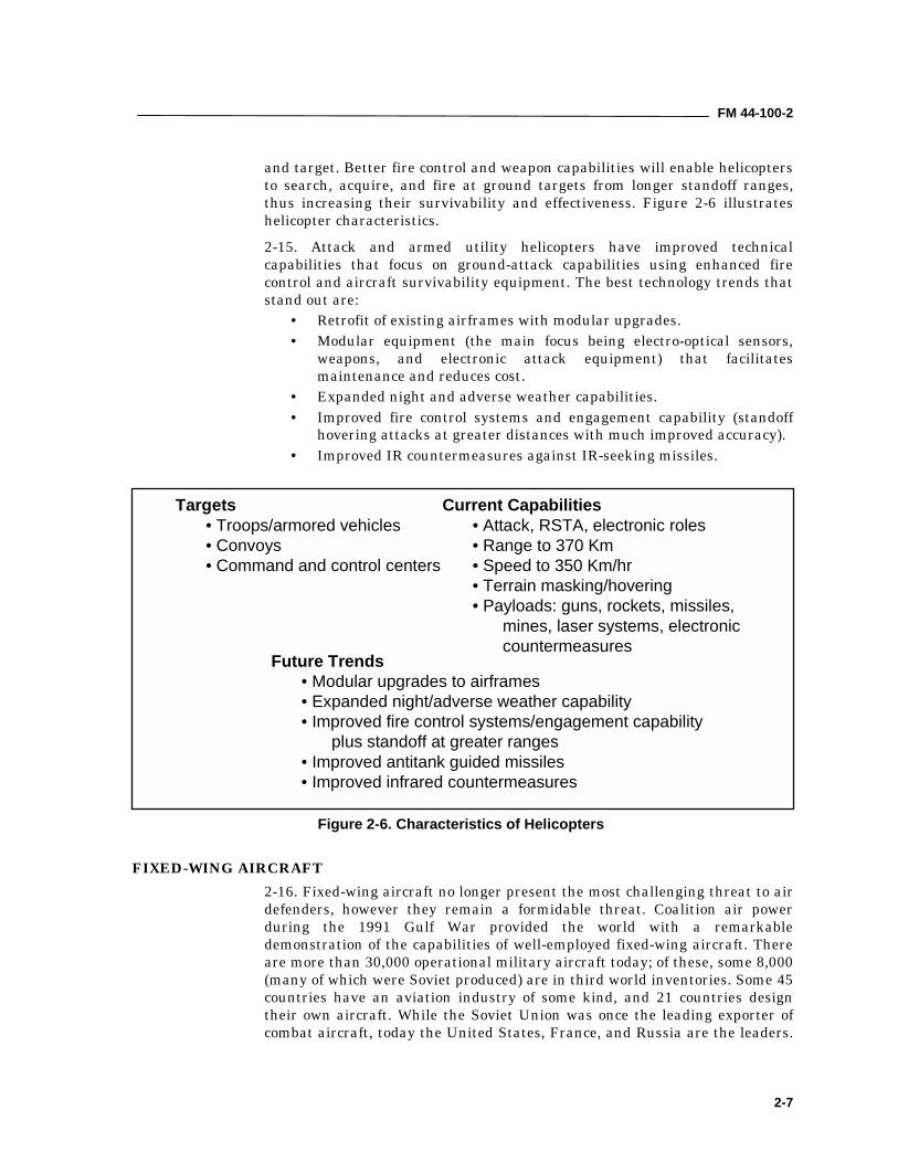
and target. Better fire control and weapon capabilities will enable helicoptersto search, acquire, and fire at ground targets from longer standoff ranges,thus increasing their survivability and effectiveness. Figure 2-6 illustrateshelicopter characteristics.2-15. Attack and armed utility helicopters have improved technicalcapabilities that focus on ground-attack capabilities using enhanced firecontrol and aircraft survivability equipment. The best technology trends thatstand out are:
• Retrofit of existing airframes with modular upgrades.• Modular equipment (the main focus being electro-optical sensors,
weapons, and electronic attack equipment) that facilitatesmaintenance and reduces cost.
• Expanded night and adverse weather capabilities.• Improved fire control systems and engagement capability (standoff
hovering attacks at greater distances with much improved accuracy).• Improved IR countermeasures against IR-seeking missiles.
FIXED-WING AIRCRAFT2-16. Fixed-wing aircraft no longer present the most challenging threat to airdefenders, however they remain a formidable threat. Coalition air powerduring the 1991 Gulf War provided the world with a remarkabledemonstration of the capabilities of well-employed fixed-wing aircraft. Thereare more than 30,000 operational military aircraft today; of these, some 8,000(many of which were Soviet produced) are in third world inventories. Some 45countries have an aviation industry of some kind, and 21 countries designtheir own aircraft. While the Soviet Union was once the leading exporter ofcombat aircraft, today the United States, France, and Russia are the leaders.
Targets• Troops/armored vehicles• Convoys• Command and control centers
Current Capabilities• Attack, RSTA, electronic roles• Range to 370 Km• Speed to 350 Km/hr• Terrain masking/hovering• Payloads: guns, rockets, missiles,
mines, laser systems, electroniccountermeasures
Future Trends• Modular upgrades to airframes• Expanded night/adverse weather capability• Improved fire control systems/engagement capability
plus standoff at greater ranges• Improved antitank guided missiles• Improved infrared countermeasures
Figure 2-6. Characteristics of Helicopters
FM 44-100-2
2-8
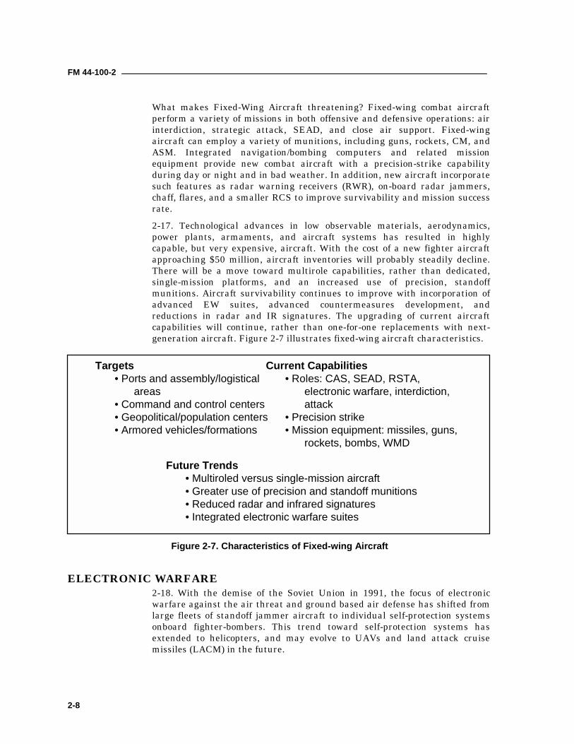
What makes Fixed-Wing Aircraft threatening? Fixed-wing combat aircraftperform a variety of missions in both offensive and defensive operations: airinterdiction, strategic attack, SEAD, and close air support. Fixed-wingaircraft can employ a variety of munitions, including guns, rockets, CM, andASM. Integrated navigation/bombing computers and related missionequipment provide new combat aircraft with a precision-strike capabilityduring day or night and in bad weather. In addition, new aircraft incorporatesuch features as radar warning receivers (RWR), on-board radar jammers,chaff, flares, and a smaller RCS to improve survivability and mission successrate.2-17. Technological advances in low observable materials, aerodynamics,power plants, armaments, and aircraft systems has resulted in highlycapable, but very expensive, aircraft. With the cost of a new fighter aircraftapproaching $50 million, aircraft inventories will probably steadily decline.There will be a move toward multirole capabilities, rather than dedicated,single-mission platforms, and an increased use of precision, standoffmunitions. Aircraft survivability continues to improve with incorporation ofadvanced EW suites, advanced countermeasures development, andreductions in radar and IR signatures. The upgrading of current aircraftcapabilities will continue, rather than one-for-one replacements with next-generation aircraft. Figure 2-7 illustrates fixed-wing aircraft characteristics.
ELECTRONIC WARFARE2-18. With the demise of the Soviet Union in 1991, the focus of electronicwarfare against the air threat and ground based air defense has shifted fromlarge fleets of standoff jammer aircraft to individual self-protection systemsonboard fighter-bombers. This trend toward self-protection systems hasextended to helicopters, and may evolve to UAVs and land attack cruisemissiles (LACM) in the future.
Targets• Ports and assembly/logistical
areas• Command and control centers• Geopolitical/population centers• Armored vehicles/formations
Current Capabilities• Roles: CAS, SEAD, RSTA,
electronic warfare, interdiction, attack
• Precision strike• Mission equipment: missiles, guns,
rockets, bombs, WMD
Future Trends• Multiroled versus single-mission aircraft• Greater use of precision and standoff munitions• Reduced radar and infrared signatures• Integrated electronic warfare suites
Figure 2-7. Characteristics of Fixed-wing Aircraft
FM 44-100-2
2-9
WEAPONS OF MASS DESTRUCTION2-19. Any nation with the will and resources can turn their legitimatenuclear, medical, and chemical industries to weapons production. This threatexists in all regions of the world, from states with long-established programsto those with emerging capabilities. Despite the dissolution of the WarsawPact, the downfall of communism in the former Soviet Union, and extensiveefforts to negotiate treaties that would reduce the number of nuclear weaponsand eliminate chemical and biological weapons from military arsenals, thenumber of countries pursuing NBC weapons programs continues to increase.2-20. Russia and China currently possess nuclear weapons and there aremany other nations of nuclear proliferation concern. As many as 26 countriesare developing, or are suspected of developing, chemical weapons.2-21. Principal doctrine for chemical weapons use by threat nations is tomaintain the momentum of an attack and to degrade their enemy’s capabilityto fight. Chemical and biological agents can be delivered to target areasvirtually anywhere in a theater of operation. Delivery means include ballisticmissiles, aircraft bombs or rockets and spray, multiple rocket launchers,mortars, conventional artillery, CM, UAV, and Special Forces.2-22. Nuclear weapons cause casualties and materiel damage through theeffects of blast, thermal radiation, and nuclear radiation. Biological agents,consisting of pathogens and toxins, produce diseases in soldiers, therebyreducing their ability to accomplish their missions. These agents areprimarily an inhalation threat. Threat forces will employ chemical agents toexpose soldiers to a respiratory and percutaneous agent threat by attackingwith non-persistent and persistent agents. Persistent agents will also be usedto contaminate personal clothing, equipment, and materiel. This willmandate the diversion of resources to decontaminate personnel andequipment.2-23. Insurgent or terrorist groups could manufacture or acquire chemicaland biological weapons to attack AD forces and other high-payoff targets.Small laboratories, such as school labs, or the drug labs used for processingcocaine, can produce some chemical and biological warfare agents.2-24. Threat nations will employ NBC weapons to incapacitate or killpersonnel. In addition, unit effectiveness decreases while operating in acontaminated environment due to fear, the requirement to wear protectiveclothing, and the need to decontaminate personnel and equipment. ADAunits throughout the theater will be high-priority targets for NBC attack.The air defense commander and staff must, therefore, train their soldiers andunits for operations in an NBC environment.
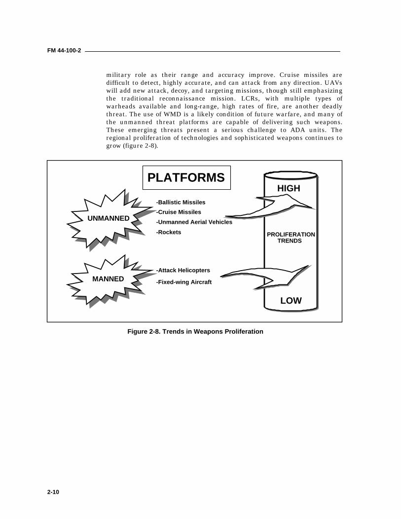
SUMMARY2-25. Numbers of countries with the potential to present regional challengesto the United States and its allies will increase. While traditional air threats,such as fixed-wing aircraft and helicopters, will continue to improve, theacquisition of new, lower-cost, unmanned threats such as ballistic missiles,CMs, UAVs, and LCRs will add greater lethality. Ballistic missiles, inaddition to being effective terror weapons, will have a more significant
FM 44-100-2
2-10
military role as their range and accuracy improve. Cruise missiles aredifficult to detect, highly accurate, and can attack from any direction. UAVswill add new attack, decoy, and targeting missions, though still emphasizingthe traditional reconnaissance mission. LCRs, with multiple types ofwarheads available and long-range, high rates of fire, are another deadlythreat. The use of WMD is a likely condition of future warfare, and many ofthe unmanned threat platforms are capable of delivering such weapons.These emerging threats present a serious challenge to ADA units. Theregional proliferation of technologies and sophisticated weapons continues togrow (figure 2-8).
PLATFORMS
LOW
HIGH-Ballistic Missiles-Cruise Missiles-Unmanned Aerial Vehicles-Rockets
-Attack Helicopters
-Fixed-wing AircraftMANNED
UNMANNED
PROLIFERATIONTRENDS
Figure 2-8. Trends in Weapons Proliferation
3-1
Chapter 3
Short Range Air DefenseThis chapter provides information on short range air defense (SHORAD),systems currently in the force. SHORAD weapons are employed insupport of maneuver forces. They defend personnel and assets againstattack by enemy aerial platforms. They are also employed in rear areas todefend air bases, forces, key installations, and other vital assets.SHORAD systems include: Stinger (MANPADS), Bradley StingerFighting Vehicle (BSFV), Linebacker, and the Avenger system.
MANPADS STINGER3-1. Stinger missiles are deployed as the missile component of the Avengermissile system, as the missile component of MANPADS teams, and as themissile component of the Linebacker. A MANPADS team is also part of theBradley Stinger Fighting Vehicle.3-2. The Stinger MANPADS team carries a manportable, shoulder-fired,infrared or IR/NUV seeking missile that requires no control from the gunnerafter firing. It has an identification, friend or foe (IFF) interrogator that aidsthe gunner and team chief in identifying targets. The team consists of agunner and team chief.
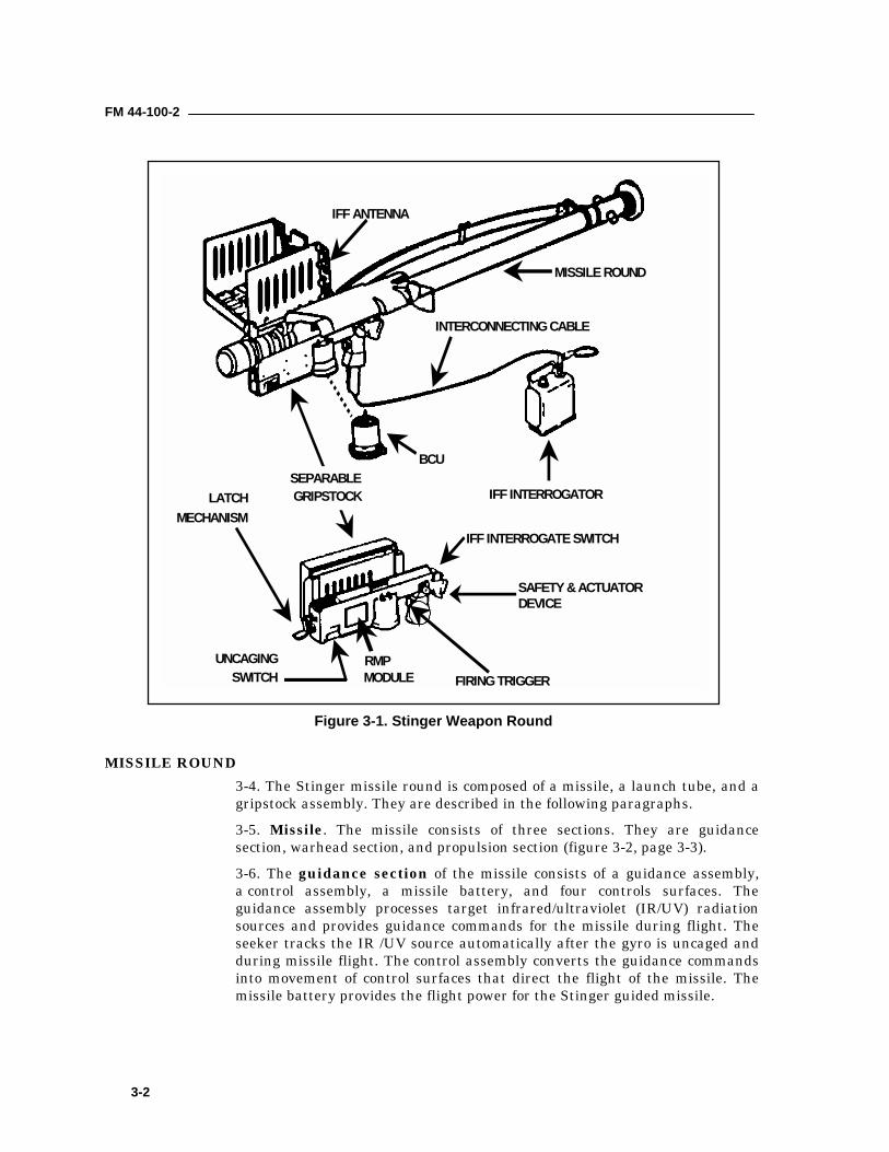
WEAPON ROUND3-3. The Stinger Man Portable Air Defense System (MANPADS) is ashoulder-fired, self-contained, close-in air defense weapon used by the UnitedStates and many foreign countries. Stinger is an infrared (IR) orinfrared/negative ultraviolet (IR/NUV) seeking, fire-and-forget weapon,allowing the gunner to engage another target or take cover immediately afterlaunch (figure 3-1, page 3-2). The system is self-contained, including its ownelectrical power, argon coolant, and IFF system. There are three versions ofthe missile: Basic, POST (Passive Optical Seeker Technique), and RMP(Reprogrammable Microprocessor). Basic Stinger has limited countermeasurecapabilities, Stinger-POST has improved countermeasure capabilities, andStinger-RMP has further refinements to its countermeasure capabilities. TheRMP version has the ability to be reprogrammed to meet an ever-changingthreat without hardware redesign or replacement. The RMP missile uses atwo color, infrared and ultraviolet, detector and advanced algorithms to helpacquire targets. This advanced capability allows the missile to effectivelydiscriminate between targets, flares, and background clutter therebypreventing false engagements. Unlike the basic Stinger missile, the RMP hasthe capability to track and destroy high-performance, fixed-wing aircraft,unmanned aerial vehicles, and cruise missiles in clutter and at tacticalranges.
FM 44-100-2
3-2
MISSILE ROUND3-4. The Stinger missile round is composed of a missile, a launch tube, and agripstock assembly. They are described in the following paragraphs.3-5. Missile. The missile consists of three sections. They are guidancesection, warhead section, and propulsion section (figure 3-2, page 3-3).3-6. The guidance section of the missile consists of a guidance assembly,a control assembly, a missile battery, and four controls surfaces. Theguidance assembly processes target infrared/ultraviolet (IR/UV) radiationsources and provides guidance commands for the missile during flight. Theseeker tracks the IR /UV source automatically after the gyro is uncaged andduring missile flight. The control assembly converts the guidance commandsinto movement of control surfaces that direct the flight of the missile. Themissile battery provides the flight power for the Stinger guided missile.
INTERCONNECTING CABLE
IFF INTERROGATOR
BCU
RMPMODULE
UNCAGINGSWITCH
SAFETY & ACTUATORDEVICE
LATCHMECHANISM
FIRING TRIGGER
IFF INTERROGATE SWITCH
IFF ANTENNA
MISSILE ROUND
SEPARABLE GRIPSTOCK
Figure 3-1. Stinger Weapon Round
FM 44-100-2
3-3
3-7. The warhead section consists of a fuse assembly and a quantity ofexplosives, all within a cylindrical case. After the flight motor ignites, thefuse arms the warhead. The fuse can detonate the warhead in three ways: bymeans of a low impact switch, by a hard target sensor, or by self-destructing(should target intercept not occur after launch).3-8. The propulsion for the missile is provided by a separable launch (eject)motor and a dual thrust flight motor. The launch motor provides initialthrust that ejects the missile from the launch tube. It allows the missile tocoast a safe distance (28 feet or 8.53 meters) from the gunner prior to ignitionof the flight motor. The launch motor is expended and separated from theflight motor and falls a safe distance forward of the gunner. At separation, alanyard attached to the launch motor pulls the shorting plug from the flightmotor ignition circuit to ignite the flight motor. The flight motor providespropulsion during missile flight. Part of the propulsion system is the tailassembly. The tail assembly consists of four folding tail fins that provide rolland missile stability.
3-9. Launch Tube Assembly. The launch tube assembly (figure 3-3, page 3-4) is a fiberglass tube that houses the missile. It provides the means totransport, aim, and fire the missile. The launch tube provides the mainsupport for all other parts of the weapon round. Both ends of the launch tubeare sealed with breakable disks. The front disk is transparent to IR radiation,allowing the radiation to reach the heat-sensitive missile seeker. The frontdisk breaks outward at launch, and the aft disk blows out as the launchmotor ignites. A desiccant cartridge and humidity indicator measures thehumidity level in the sealed tube. The hinged sight assembly attached to thelaunch tube allows the gunner to sight the weapon, determine target range,superelevate the weapon, and hear the audible tones through the acquisitionindicators. The eye shield attached to the sight frame protects the gunner's
GUIDANCESECTION
WARHEAD SECTION
PROPULSION SECTION
LAUNCH MOTORTAIL FINS (4)
CONTROL SURFACES (4)
SEEKER HEAD
FLIGHT MOTOR
Figure 3-2. Stinger Missile
FM 44-100-2
3-4
left eye during launch. The launch tube is destroyed and discarded after themissile is fired.
3-10. Gripstock Assembly. The gripstock is attached to and removed from alaunch tube by means of a latch (figure 3-1, page 3-2). Located on thegripstock assembly are the safety and actuator device, uncaging switch, firingtrigger, IFF antenna assembly, IFF INTERROGATE switch, IFF interrogatorconnector, and Battery Coolant Unit (BCU) receptacle. After a missile islaunched, the separable gripstock is removed from the launch tube for reuse.It can be reused until failure.3-11. When the IFF antenna assembly is deployed and the interrogator isconnected to the gripstock, it is capable of interrogating aerial platforms andreceiving coded replies. After a missile is fired the IFF antenna assemblyfolds into a holder on the right side of the gripstock assembly.3-12. The BCU is used to energize the weapon's electrical circuits and to coolthe IR detector in the missile's seeker prior to launch of the missile. Itcontains a thermal battery to provide power for preflight operation, andpressurized argon gas coolant.
INTERROGATOR FRIEND OR FOE SYSTEM3-13. Stinger is equipped with an AN/PPX-3 A/B IFF subsystem to aid in theidentification of aerial platforms. The IFF system classifies aerial platformsas either friendly or unknown. It does not identify hostile aerial platforms.IFF components include the IFF interrogator and an interconnecting cable.3-14. The gunner initiates the IFF sequence by pressing the IFFINTERROGATE switch on the gripstock assembly. The interrogator attached
DESSICANT CARTRIDGE/HUMIDITY INDICATOR
UNIT
BLOWOUT DISK
ACQUISITIONINDICATORS
SIGHTASSEMBLYFOLDED
EYESHIELDIR WINDOW
Figure 3-3. Stinger Launch Tube
FM 44-100-2
3-5
to the gunner's belt sends a coded signal to the aerial platform. Once thegunner issues a challenge, the rest of the sequence is automatic.
3-15. The aerial platform's transponder then prepares and sends a codedreply. The reply is received by the Stinger IFF antenna and is routed to theinterrogator for decoding. The interrogator converts the reply into an audibletone that is then routed via the interconnecting cable to the gunner as afriendly tone. If the aerial platform's transponder sends an incorrect reply tothe IFF challenge, the reply is processed by the IFF system into an unknowntone. Aerial platforms not equipped with transponders will not reply to thechallenge, and this is interpreted as an unknown tone. The gunner hears thefriendly or unknown tone immediately after challenging the aerial platform.3-16. The IFF challenge is coded in Mode 4 form or Mode 3 form. A friendlyMode 4 reply is considered a true friend reply. A friendly Mode 3 reply isconsidered only as a possible friend reply.3-17. Support equipment for the IFF (figure 3-4) includes a programmerbattery charger AN/GSX-1, computer KIR-1C/TSEC (with power supplymodel ZAC A/1), and two code changing keys KOI-18/TSEC. The computerand code changing keys, when set with classified code, are classifiedCONFIDENTIAL, and must be safeguarded as outlined in TB 380-41. Theinterrogator (specifically, the reply evaluator module within the interrogator)
CABLE TO115V POWER
SOURCE
COMPUTER &POWERSUPPLY
CODECHANGING
KEYS
PROGRAMMERBATTERYCHARGER
INTERROGATOR
Figure 3-4. IFF Support Equipment
FM 44-100-2
3-6
is also classified CONFIDENTIAL, and proper security measures must betaken for it. An IFF subsystem training set is available for training purposes.See TM 9-1425-429-12 for IFF support equipment operation instructions.
WEAPON ROUND CONTAINER3-18. A weapon round container provides environmental protection duringshipping and storage. The container is equipped with one set of ear plugs,four latches, handles for two-man carry, a pressure relief valve, a humidityindicator, and a BCU storage area for 3 to 5 BCUs (figure 3-5).
EMPLOYMENT OF STINGER3-19. The Stinger operates by the gunner sighting on a target. The gunnercenters the target in the sight range ring. The gunner interrogates the targetby pressing the IFF interrogator switch and listens for an IFF response. Ifthe response is not a friend, he continues tracking and ranging the target.When the target is within range, he operates a safety and actuation device.When a distinct acquisition tone is heard, he presses and holds the uncagingswitch. After identifying the target as hostile (aided and assisted by the teamchief) the gunner will superelevate the weapon. He will then place the targetin proper lead reticule and, if IR tone is still distinct, squeeze and hold thefiring trigger. The gunner continues to track the target for three to fiveseconds. The BCU must be removed in less than three minutes after firing toprevent damage to the reusable gripstock.3-20. Stinger's primary role is to provide Air Defense for forward combatelements against aerial platforms. Stinger defends HIMAD units, high-
HUMIDITY INDICATOR
Figure 3-5. Weapon Round Container
FM 44-100-2
3-7
priority maneuver units, and high-priority critical assets (such as commandposts, trains, ammunition storage point (ASP) and POL). Stingercomplements other ADA systems when priorities and the situation permit.
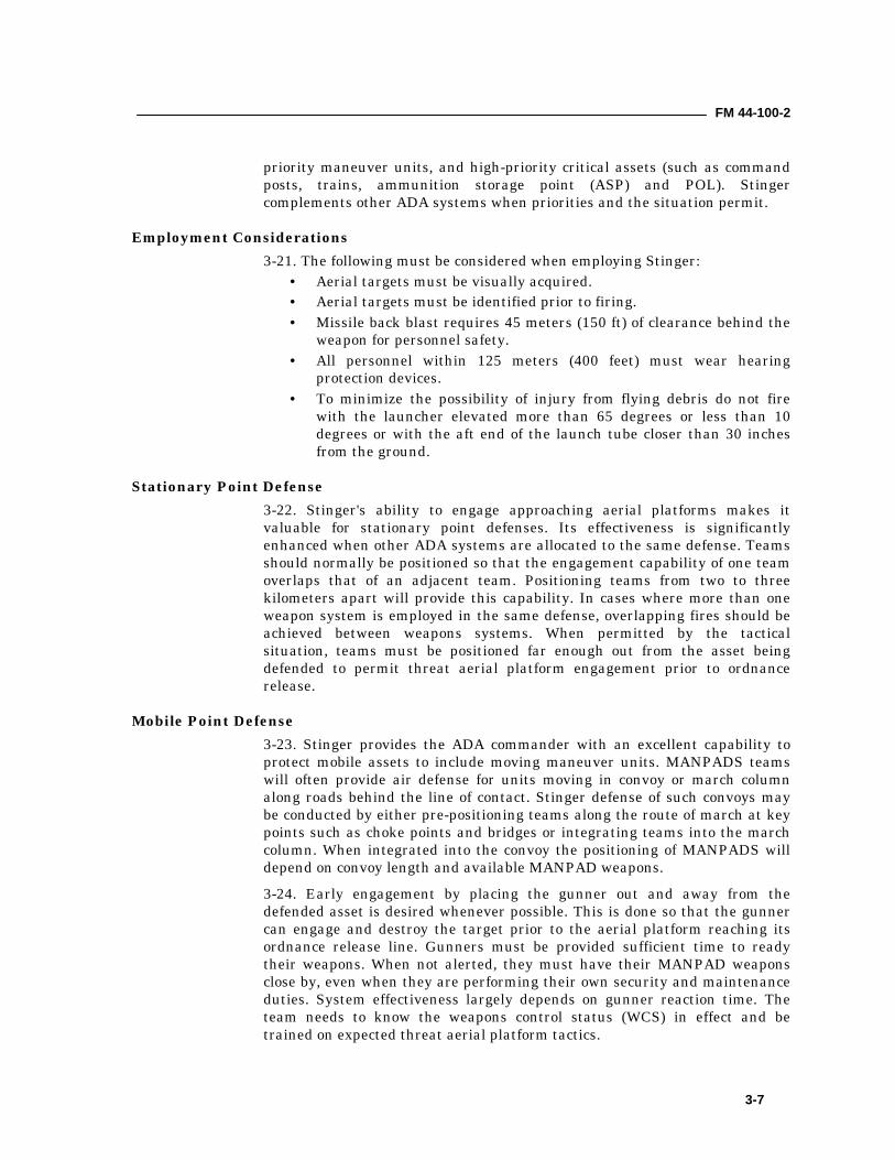
Employment Considerations3-21. The following must be considered when employing Stinger:
• Aerial targets must be visually acquired.• Aerial targets must be identified prior to firing.• Missile back blast requires 45 meters (150 ft) of clearance behind the
weapon for personnel safety.• All personnel within 125 meters (400 feet) must wear hearing
protection devices.• To minimize the possibility of injury from flying debris do not fire
with the launcher elevated more than 65 degrees or less than 10degrees or with the aft end of the launch tube closer than 30 inchesfrom the ground.
Stationary Point Defense3-22. Stinger's ability to engage approaching aerial platforms makes itvaluable for stationary point defenses. Its effectiveness is significantlyenhanced when other ADA systems are allocated to the same defense. Teamsshould normally be positioned so that the engagement capability of one teamoverlaps that of an adjacent team. Positioning teams from two to threekilometers apart will provide this capability. In cases where more than oneweapon system is employed in the same defense, overlapping fires should beachieved between weapons systems. When permitted by the tacticalsituation, teams must be positioned far enough out from the asset beingdefended to permit threat aerial platform engagement prior to ordnancerelease.
Mobile Point Defense3-23. Stinger provides the ADA commander with an excellent capability toprotect mobile assets to include moving maneuver units. MANPADS teamswill often provide air defense for units moving in convoy or march columnalong roads behind the line of contact. Stinger defense of such convoys maybe conducted by either pre-positioning teams along the route of march at keypoints such as choke points and bridges or integrating teams into the marchcolumn. When integrated into the convoy the positioning of MANPADS willdepend on convoy length and available MANPAD weapons.3-24. Early engagement by placing the gunner out and away from thedefended asset is desired whenever possible. This is done so that the gunnercan engage and destroy the target prior to the aerial platform reaching itsordnance release line. Gunners must be provided sufficient time to readytheir weapons. When not alerted, they must have their MANPAD weaponsclose by, even when they are performing their own security and maintenanceduties. System effectiveness largely depends on gunner reaction time. Theteam needs to know the weapons control status (WCS) in effect and betrained on expected threat aerial platform tactics.
FM 44-100-2
3-8
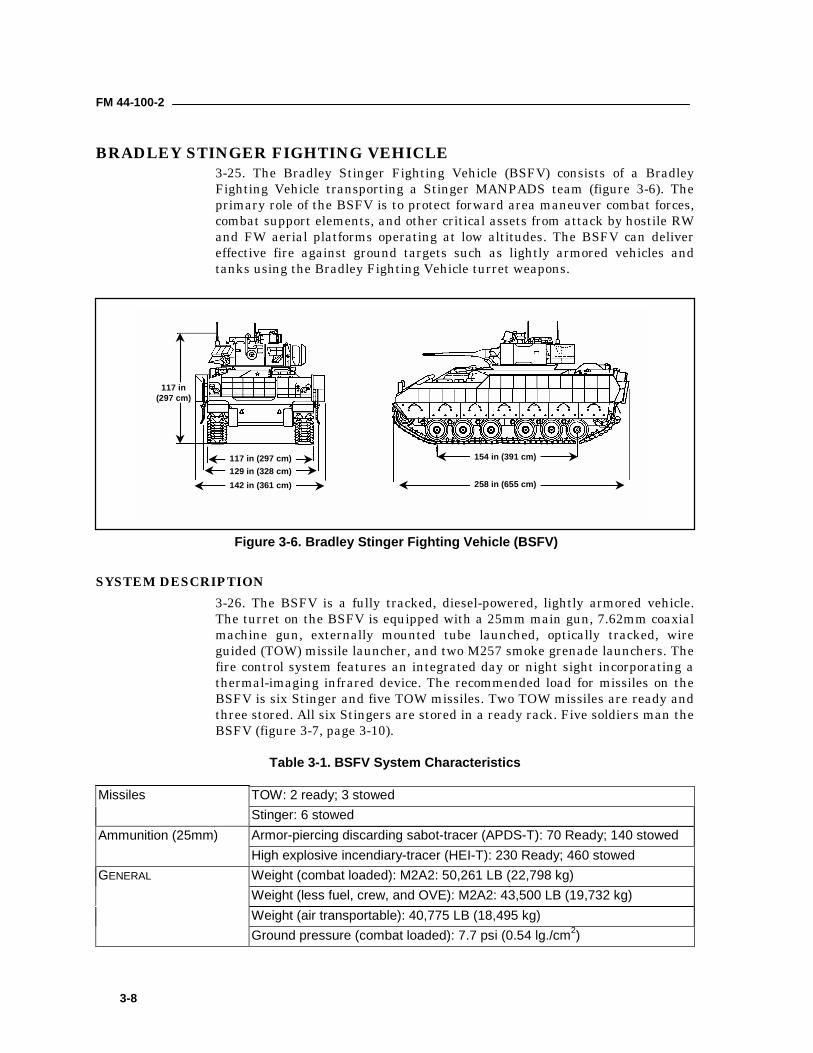
BRADLEY STINGER FIGHTING VEHICLE3-25. The Bradley Stinger Fighting Vehicle (BSFV) consists of a BradleyFighting Vehicle transporting a Stinger MANPADS team (figure 3-6). Theprimary role of the BSFV is to protect forward area maneuver combat forces,combat support elements, and other critical assets from attack by hostile RWand FW aerial platforms operating at low altitudes. The BSFV can delivereffective fire against ground targets such as lightly armored vehicles andtanks using the Bradley Fighting Vehicle turret weapons.
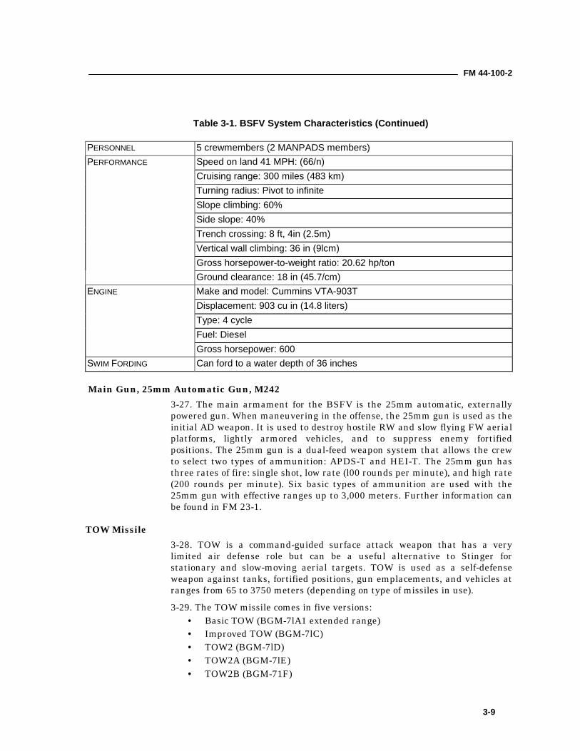
SYSTEM DESCRIPTION3-26. The BSFV is a fully tracked, diesel-powered, lightly armored vehicle.The turret on the BSFV is equipped with a 25mm main gun, 7.62mm coaxialmachine gun, externally mounted tube launched, optically tracked, wireguided (TOW) missile launcher, and two M257 smoke grenade launchers. Thefire control system features an integrated day or night sight incorporating athermal-imaging infrared device. The recommended load for missiles on theBSFV is six Stinger and five TOW missiles. Two TOW missiles are ready andthree stored. All six Stingers are stored in a ready rack. Five soldiers man theBSFV (figure 3-7, page 3-10).
Table 3-1. BSFV System Characteristics
Missiles TOW: 2 ready; 3 stowedStinger: 6 stowed
Ammunition (25mm) Armor-piercing discarding sabot-tracer (APDS-T): 70 Ready; 140 stowedHigh explosive incendiary-tracer (HEI-T): 230 Ready; 460 stowed
GENERAL Weight (combat loaded): M2A2: 50,261 LB (22,798 kg)Weight (less fuel, crew, and OVE): M2A2: 43,500 LB (19,732 kg)Weight (air transportable): 40,775 LB (18,495 kg)Ground pressure (combat loaded): 7.7 psi (0.54 lg./cm2)
117 in(297 cm)
117 in (297 cm)129 in (328 cm)142 in (361 cm)
154 in (391 cm)
258 in (655 cm)
Figure 3-6. Bradley Stinger Fighting Vehicle (BSFV)
FM 44-100-2
3-9
Table 3-1. BSFV System Characteristics (Continued)
PERSONNEL 5 crewmembers (2 MANPADS members)PERFORMANCE Speed on land 41 MPH: (66/n)
Cruising range: 300 miles (483 km)Turning radius: Pivot to infiniteSlope climbing: 60%Side slope: 40%Trench crossing: 8 ft, 4in (2.5m)Vertical wall climbing: 36 in (9lcm)Gross horsepower-to-weight ratio: 20.62 hp/tonGround clearance: 18 in (45.7/cm)
ENGINE Make and model: Cummins VTA-903TDisplacement: 903 cu in (14.8 liters)Type: 4 cycleFuel: DieselGross horsepower: 600
SWIM FORDING Can ford to a water depth of 36 inches
Main Gun, 25mm Automatic Gun, M2423-27. The main armament for the BSFV is the 25mm automatic, externallypowered gun. When maneuvering in the offense, the 25mm gun is used as theinitial AD weapon. It is used to destroy hostile RW and slow flying FW aerialplatforms, lightly armored vehicles, and to suppress enemy fortifiedpositions. The 25mm gun is a dual-feed weapon system that allows the crewto select two types of ammunition: APDS-T and HEI-T. The 25mm gun hasthree rates of fire: single shot, low rate (l00 rounds per minute), and high rate(200 rounds per minute). Six basic types of ammunition are used with the25mm gun with effective ranges up to 3,000 meters. Further information canbe found in FM 23-1.
TOW Missile3-28. TOW is a command-guided surface attack weapon that has a verylimited air defense role but can be a useful alternative to Stinger forstationary and slow-moving aerial targets. TOW is used as a self-defenseweapon against tanks, fortified positions, gun emplacements, and vehicles atranges from 65 to 3750 meters (depending on type of missiles in use).3-29. The TOW missile comes in five versions:
• Basic TOW (BGM-7lA1 extended range)• Improved TOW (BGM-7lC)• TOW2 (BGM-7lD)• TOW2A (BGM-7lE)• TOW2B (BGM-71F)
FM 44-100-2
3-10
3-30. Each version is an improvement over the previous missile. Primaryimprovements are in the areas of penetration, effective range, and usabilityin adverse firing conditions. Additional information can be found in FM 23-1.
M240C 7.62 Coaxial Machine Gun3-31. The M240C 7.62mm machine gun is a coaxial, belt-fed, gas operated,fully automatic weapon that can be used against fixed and rotary wing aerialplatforms, UAVs, and unarmored vehicles. However, its maximum range of900 meters limits its usefulness as an air defense weapon. Furtherinformation can be found in FM 23-1.
EMPLOYMENT OF BSFV3-32. The primary mission of the BSFV squad is to defeat multiple aerialthreats both moving and stationary. See table 3-2, page 3-11, for weaponusage guidelines.
Offensive Employment3-33. BSFV units will accompany the main attack in offensive situations.When moving, or in situations with brief halts, the 25mm chain gun is theinitial weapon with an effective range of two kilometers against aerial attack.Consequently, BSFVs should maneuver no further than 1000 meters apart toprovide mutual support.3-34. The Stinger team should be dismounted to provide air defense of theforces when the attacking forces are stalled or at the objective. Dismounting aStinger team is a squad leader's decision based on the artillery threat, theability of the FU to overwatch the maneuver force, and anticipated futuremovements. The Stinger can overwatch from up to one kilometer to the rear
DRIVER
SQUADLEADER
SENIORGUNNER
STINGERGUNNER
2 TOWS READYIN TOW POD
4 STINGER IN RACK1 STINGER RTF
Figure 3-7. BSFV Crew
FM 44-100-2
3-11
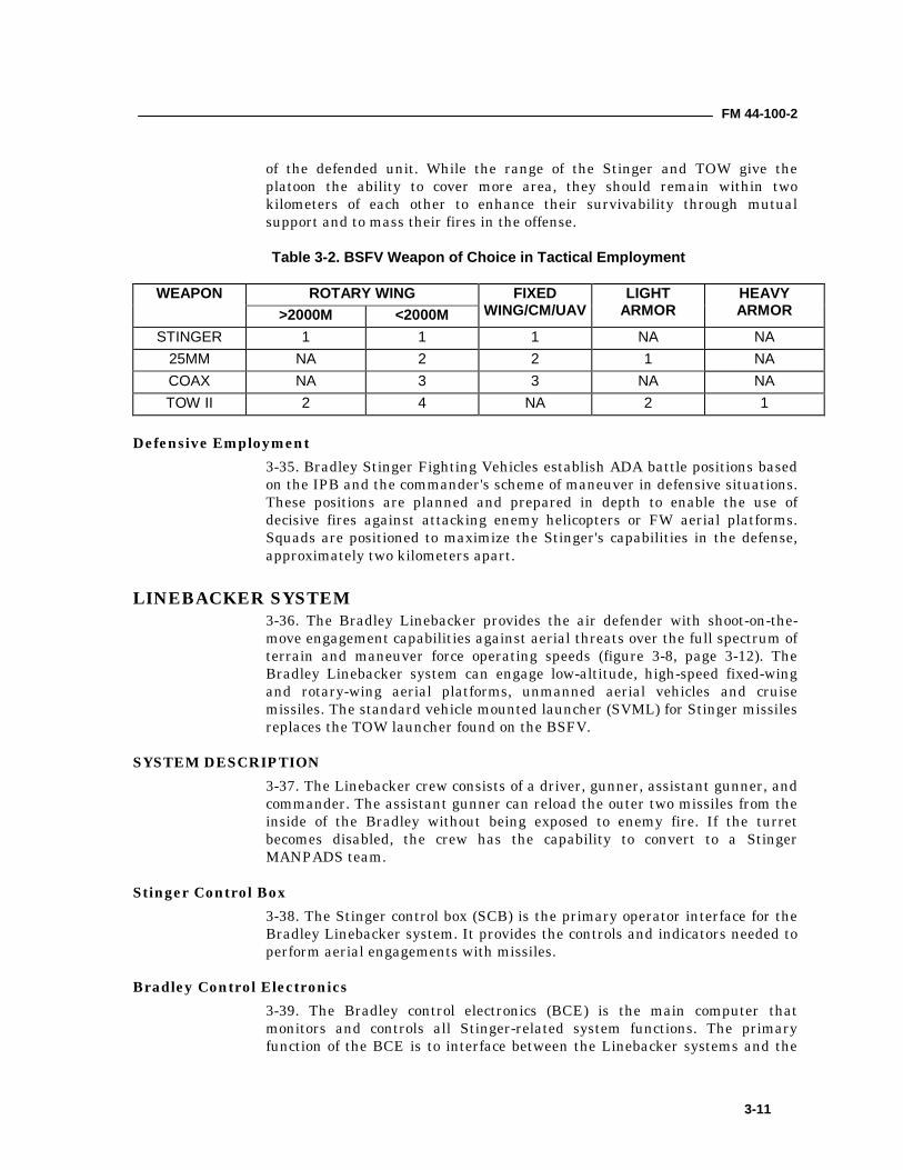
of the defended unit. While the range of the Stinger and TOW give theplatoon the ability to cover more area, they should remain within twokilometers of each other to enhance their survivability through mutualsupport and to mass their fires in the offense.
Table 3-2. BSFV Weapon of Choice in Tactical Employment
ROTARY WINGWEAPON>2000M <2000M
FIXEDWING/CM/UAV
LIGHTARMOR
HEAVYARMOR
STINGER 1 1 1 NA NA25MM NA 2 2 1 NACOAX NA 3 3 NA NATOW II 2 4 NA 2 1
Defensive Employment3-35. Bradley Stinger Fighting Vehicles establish ADA battle positions basedon the IPB and the commander's scheme of maneuver in defensive situations.These positions are planned and prepared in depth to enable the use ofdecisive fires against attacking enemy helicopters or FW aerial platforms.Squads are positioned to maximize the Stinger's capabilities in the defense,approximately two kilometers apart.
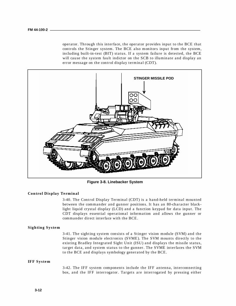
LINEBACKER SYSTEM3-36. The Bradley Linebacker provides the air defender with shoot-on-the-move engagement capabilities against aerial threats over the full spectrum ofterrain and maneuver force operating speeds (figure 3-8, page 3-12). TheBradley Linebacker system can engage low-altitude, high-speed fixed-wingand rotary-wing aerial platforms, unmanned aerial vehicles and cruisemissiles. The standard vehicle mounted launcher (SVML) for Stinger missilesreplaces the TOW launcher found on the BSFV.
SYSTEM DESCRIPTION3-37. The Linebacker crew consists of a driver, gunner, assistant gunner, andcommander. The assistant gunner can reload the outer two missiles from theinside of the Bradley without being exposed to enemy fire. If the turretbecomes disabled, the crew has the capability to convert to a StingerMANPADS team.
Stinger Control Box3-38. The Stinger control box (SCB) is the primary operator interface for theBradley Linebacker system. It provides the controls and indicators needed toperform aerial engagements with missiles.
Bradley Control Electronics3-39. The Bradley control electronics (BCE) is the main computer thatmonitors and controls all Stinger-related system functions. The primaryfunction of the BCE is to interface between the Linebacker systems and the
FM 44-100-2
3-12
operator. Through this interface, the operator provides input to the BCE thatcontrols the Stinger system. The BCE also monitors input from the system,including built-in-test (BIT) status. If a system failure is detected, the BCEwill cause the system fault indictor on the SCB to illuminate and display anerror message on the control display terminal (CDT).
Control Display Terminal3-40. The Control Display Terminal (CDT) is a hand-held terminal mountedbetween the commander and gunner positions. It has an 80-character black-light liquid crystal display (LCD) and a function keypad for data input. TheCDT displays essential operational information and allows the gunner orcommander direct interface with the BCE.
Sighting System3-41. The sighting system consists of a Stinger vision module (SVM) and theStinger vision module electronics (SVME). The SVM mounts directly to theexisting Bradley Integrated Sight Unit (ISU) and displays the missile status,target data, and system status to the gunner. The SVME interfaces the SVMto the BCE and displays symbology generated by the BCE.
IFF System3-42. The IFF system components include the IFF antenna, interconnectingbox, and the IFF interrogator. Targets are interrogated by pressing either
STINGER MISSILE POD
Figure 3-8. Linebacker System
FM 44-100-2
3-13
inner thumb switch forward on the gunner’s hand station. The IFF antennatransmits signals from the IFF interrogator and receives the response signalsfrom the subject target. The result of the interrogation is announced over theintercom system as a series of tones. The IFF interrogator is an AN/PPX-3Binterrogator. The IFF can be dismounted to support MANPADS Stingeroperations.
Missile System3-43. The missile system consists of the SVLM and the Interface ElectronicAssembly (IEA). The missile launcher holds up to four ready-to-fire Stingermissiles. It contains two argon bottles to cool down missile seeker heads, andtwo Launcher Electronic Assemblies (LEA) that control missile selection, gyrodrive, coolant control, cycling, signal processing, and firing. Loading andunloading missiles is accomplished through upper and lower access doors.The missile launcher is mounted on a retractable platform. The platformcontains an erector motor and a latch solenoid/sensor combination to ensurethe platform is locked in place prior to missile firing. The launcher ismounted in an armor protective box that also provides an alignment plate forazimuth boresighting.
Command and Control3-44. The Linebacker is equipped with the single channel ground andairborne radio system (SINCGARS), enhanced position, location andreporting system (EPLRS), precision lightweight global positioning systemreceiver (PLGR), simplified handheld terminal unit (SHTU) or handheldterminal unit (HTU), and slew-to-cue capability. This allows the Linebackerto receive early warning information and enables the Linebacker toaccomplish early engagement.
Missile Countermeasure Device3-45. The Missile Countermeasure Device (MCD) system is mounted on top ofthe turret forward of the gunner's hatch. It generates infrared radiation (IR)and directs it through the front window of the MCD unit. When the turret isturned toward an incoming antitank guided missile (ATGM), the IR causesthe operation of the missile to lose electronic guidance control by sendinginaccurate course correction signals. The inaccurate signals cause the missileto fly off course and crash. The MCD can defeat a variety of current first andsecond generation ATGMS (TOW, Dragon, HOT, Milan, AT-4-5-6-7 andSwingfire). The system effectiveness can be limited by the angle of coverage,the battlefield's haze, and any dust or mud accumulated on the systemwindow.
Digital Compass System3-46. The Digital Compass System (DCS) can operate in conjunction with thePLGR or as a stand-alone system. It provides the crew with directionalprompts allowing them to navigate from one point to another point moreefficiently. A liquid crystal display indicates range and direction to the target,along with directional prompts. The DCS, when used in conjunction with the
FM 44-100-2
3-14
laser range finder, provides the commander with the information needed tocall for fire.
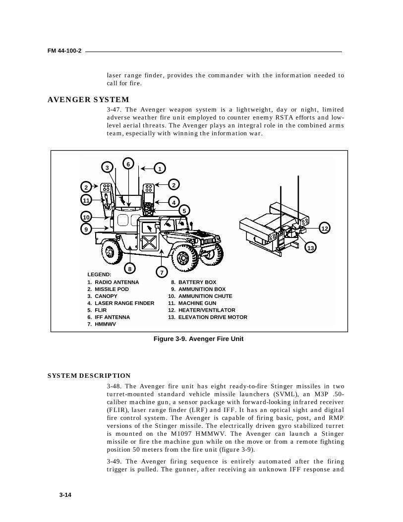
AVENGER SYSTEM3-47. The Avenger weapon system is a lightweight, day or night, limitedadverse weather fire unit employed to counter enemy RSTA efforts and low-level aerial threats. The Avenger plays an integral role in the combined armsteam, especially with winning the information war.
SYSTEM DESCRIPTION3-48. The Avenger fire unit has eight ready-to-fire Stinger missiles in twoturret-mounted standard vehicle missile launchers (SVML), an M3P .50-caliber machine gun, a sensor package with forward-looking infrared receiver(FLIR), laser range finder (LRF) and IFF. It has an optical sight and digitalfire control system. The Avenger is capable of firing basic, post, and RMPversions of the Stinger missile. The electrically driven gyro stabilized turretis mounted on the M1097 HMMWV. The Avenger can launch a Stingermissile or fire the machine gun while on the move or from a remote fightingposition 50 meters from the fire unit (figure 3-9).3-49. The Avenger firing sequence is entirely automated after the firingtrigger is pulled. The gunner, after receiving an unknown IFF response and
61
8 7
9
10
11
2
3
2
45
12
13
1. RADIO ANTENNA2. MISSILE POD3. CANOPY4. LASER RANGE FINDER5. FLIR6. IFF ANTENNA7. HMMWV
8. BATTERY BOX 9. AMMUNITION BOX10. AMMUNITION CHUTE11. MACHINE GUN12. HEATER/VENTILATOR13. ELEVATION DRIVE MOTOR
LEGEND:
Figure 3-9. Avenger Fire Unit
FM 44-100-2
3-15
having visually identified the target as hostile, will activate a missile, uncagethe seeker, and, if the target is within range, fire a missile. Immediately uponfiring the missile, the next missile is already spinning up its gyro and coolingdown. This is done without the gunner activating the next missile. TheAvenger system has the unique ability of having a backup capability ofperforming it’s mission. Should the Avenger become disabled, the missiles inthe pods can be removed, gripstocks attached, and then fired in theMANPADS configuration. Gripstocks and BCUs are stored on the Avengerduring combat missions.3-50. Onboard communications equipment consists of the Enhanced PositionLocation Reporting System (EPLRS) and the Single Channel Ground andAirborne Radio System (SINCGARS). The Avenger can be transported in C-130 and larger aerial platforms.
Turret (Gunner's Station)3-51. The Avenger turret provides the gunner with unobstructed fields of fire.It can rotate through 360° degrees of azimuth and from negative 10 degreesto positive 68 degrees in elevation. The SVML pods are mounted on each sideof the turret and contain four Stinger missiles each. Reload time is less thansix minutes.3-52. The Avenger turret is gyro-stabilized. A gyro is attached to the turretfloor that senses changes in azimuth of the HMMWV and provides errorsignals to the Electronic Control Assembly (ECA) to maintain weaponpointing when in the stabilized mode of operation.
M3P .50-Caliber Machine Gun3-53. The M3P .50-caliber machine gun is mounted on the right launch beam.It provides air defense coverage inside the missile’s dead zone, and fire unitself-defense against hostile ground fire. Linked ammunition (200 rounds) isstored in the ammunition box and fed to the gun via a flexible feed chute.
Remote Control Unit3-54. The Avenger gunner can operate the system remotely from up to adistance of 50 meters using the Remote Control Unit (RCU). The hand controlswitches and indicators on the RCU are the same as those on the gunner'sconsole. Adjustments to the FLIR console cannot be made from the RCU. Asthe environment or weather changes, it is critical that the FLIR be keptproperly adjusted at all times so that the RCU remains effective.
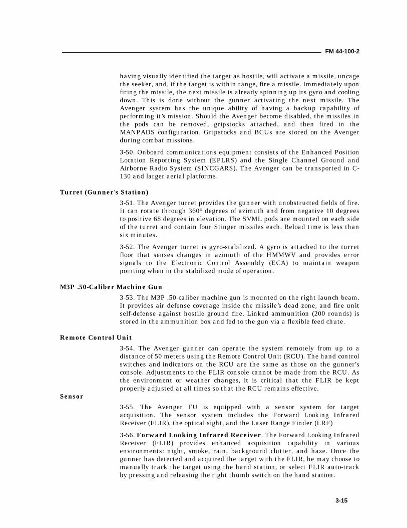
Sensor3-55. The Avenger FU is equipped with a sensor system for targetacquisition. The sensor system includes the Forward Looking InfraredReceiver (FLIR), the optical sight, and the Laser Range Finder (LRF)3-56. Forward Looking Infrared Receiver. The Forward Looking InfraredReceiver (FLIR) provides enhanced acquisition capability in variousenvironments: night, smoke, rain, background clutter, and haze. Once thegunner has detected and acquired the target with the FLIR, he may choose tomanually track the target using the hand station, or select FLIR auto-trackby pressing and releasing the right thumb switch on the hand station.
FM 44-100-2
3-16
3-57. The two auto-tracking functions on Avenger are FLIR and missile. Inmissile auto-track, the missile seeker will lock onto the target and the turretwill follow the target in azimuth and elevation, providing the Operate Mode –Track switchlight is set to Auto. In FLIR auto-track, the target must beinside the FLIR track box before pressing and releasing the right thumbswitch on the hand station.3-58. Optical Sight. To conduct a heads-up engagement using the opticalsight, the gunner looks at the sight symbology that is being super-imposedonto the combining glass and out through the canopy. This is the samesymbology that appears on the FLIR monitor, but without the auto-trackreticule and NFOV fixed reticule.3-59. Identification Friend or Foe. The Avenger IFF subsystem isactivated by the gunner. It permits the gunner to identify aerial platformsequipped with Mode 3 or Mode 4 programmed transponders as friend,possible friend, or unknown. In normal operation the system provides a codedinterrogation signal for transmission from the FU to the unidentified aerialplatform. A reply is automatically generated and transmitted by a friendlyaerial platform. Based on the IFF response and visual identification, thegunner either continues the engagement sequence or goes back tosearch/scan.3-60. Laser Range Finder. Range data from the laser range finder isprocessed by the on-board computer and is displayed to the gunner on theControl Display Terminal in meters. The computer uses this range data todetermine fire permit and lead angle information for missile and gun use. Afire permit symbol is not required to launch a missile, however it is requiredto fire the machine gun in the Air or Ground (Auto) mode.
OFFENSIVE EMPLOYMENT3-61. A decision to employ Avenger fire units in support of maneuver forcesrequires a thorough understanding of the supported commander's intent andthe establishment of disengagement criteria. Avengers may follow thebrigade in zone, providing overwatch, and protecting command and controlassets, reserve units, and artillery units. Planning should include thefollowing risk considerations when deploying Avenger in support of maneuverforces. Avengers are light-skinned vehicles with a distinct high profile andare extremely vulnerable to direct fire, small arms, and indirect fire. Thevehicle is unable to negotiate rugged terrain with side slopes exceeding 22degrees.3-62. Avengers are normally placed in a GS or GS-R supporting role.However, Avenger may be used in the direct support role, especially in lightand special divisions. At night, in adverse weather and when no other ADAsystem can perform the ADA mission, the Avenger can be integrated into alight battalion's scheme of maneuver.
DEFENSIVE EMPLOYMENT3-63. The Avenger platoon leader must perform a mission analysis, ensuringhe understands the commander's intent and the supported unit's concept ofthe operation. The Avenger platoon leader must clearly understand how

FM 44-100-2
3-17
Avengers will contribute to the force's air defense coverage. Based on theseconsiderations, the platoon leader will develop a coverage plan to support thedefensive concept of operations.
4-1
Chapter 4
Theater High Altitude Area Defense SystemThis chapter describes the Theater High Altitude Area Defense (THAAD)system. This system is deployed to defend theater and corps commanders'assets.
MISSION4-1. The THAAD system serves as a high altitude defense against ballisticmissiles. It is capable of detecting and intercepting ballistic missile threats inand above the atmosphere.
SYSTEM DESCRIPTION4-2. A THAAD battery is made up of missile rounds, launchers, a radar, aBM/C3I segment, and ground support equipment (the FUE battery in 2006will have 16 missiles, 1 radar, 2 launchers, and 1 BM/C3I segment). THAADis designed to perform its mission in a centralized, decentralized, orautonomous mode of control. It will take advantage of threat data from externalsources such as early warning/detection sensors and communications assets.
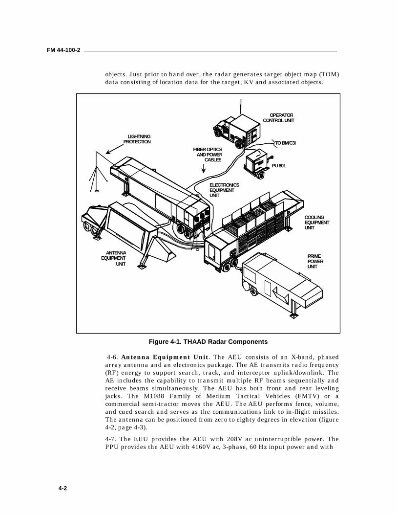
Radar4-3. The THAAD radar is a high resolution, multimode, X-band, phased-arrayradar. It is a mobile radar system capable of being transported from site tosite by aircraft and tow vehicles. The overall purpose of the radar is toidentify, classify, track, and report the position of hostile vehicles to theTHAAD battery Tactical Operations Center. The THAAD radar consists ofseveral components rather than the traditional single piece of hardware:Antenna Equipment Unit, Electronics Equipment Unit, Cooling EquipmentUnit, and Prime Power Unit. The radar components are all C141 aircrafttransportable and are roll-on/roll-off capable on FAST ships and railtransport.4-4. The radar uses fence, volume, and cued search modes, and provides firecontrol functions of surveillance, acquisition, track, discrimination, missileengagement support, and kill assessment for the THAAD system. Figure 4-1,page 4-2, shows a typical layout for the radar subsystem (the OperatorControl Unit will not be a part of the fielded system).4-5. The radar detects a potential object of interest, verifies that the detectionis of legitimate interest, and initiates the track. The radar classifies theobject as an air breathing threat, a TBM, or other. The radar classifies theTBMs as specific missiles such as ND-1 or SS-21. The radar identifies athreat TBM based on the predicted ground impact point. The radar providestrack data concerning targets, THAAD missiles, kill vehicles (KV) and other
FM 44-100-2
4-2
objects. Just prior to hand over, the radar generates target object map (TOM)data consisting of location data for the target, KV and associated objects.
4-6. Antenna Equipment Unit. The AEU consists of an X-band, phasedarray antenna and an electronics package. The AE transmits radio frequency(RF) energy to support search, track, and interceptor uplink/downlink. TheAE includes the capability to transmit multiple RF beams sequentially andreceive beams simultaneously. The AEU has both front and rear levelingjacks. The M1088 Family of Medium Tactical Vehicles (FMTV) or acommercial semi-tractor moves the AEU. The AEU performs fence, volume,and cued search and serves as the communications link to in-flight missiles.The antenna can be positioned from zero to eighty degrees in elevation (figure4-2, page 4-3).4-7. The EEU provides the AEU with 208V ac uninterruptible power. ThePPU provides the AEU with 4160V ac, 3-phase, 60 Hz input power and with
OPERATORCONTROL UNIT
TO BM/C3I
PU 801
COOLINGEQUIPMENTUNIT
PRIMEPOWERUNIT
ELECTRONICSEQUIPMENTUNIT
ANTENNAEQUIPMENT
UNIT
LIGHTNINGPROTECTION
FIBER OPTICSAND POWER
CABLES
Figure 4-1. THAAD Radar Components
FM 44-100-2
4-3
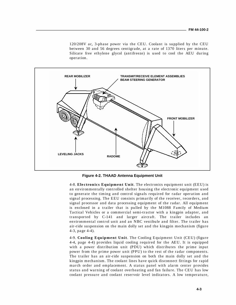
120/208V ac, 3-phase power via the CEU. Coolant is supplied by the CEUbetween 30 and 56 degrees centigrade, at a rate of 1370 liters per minute.Silicate free ethylene glycol (antifreeze) is used to cool the AEU duringoperation.
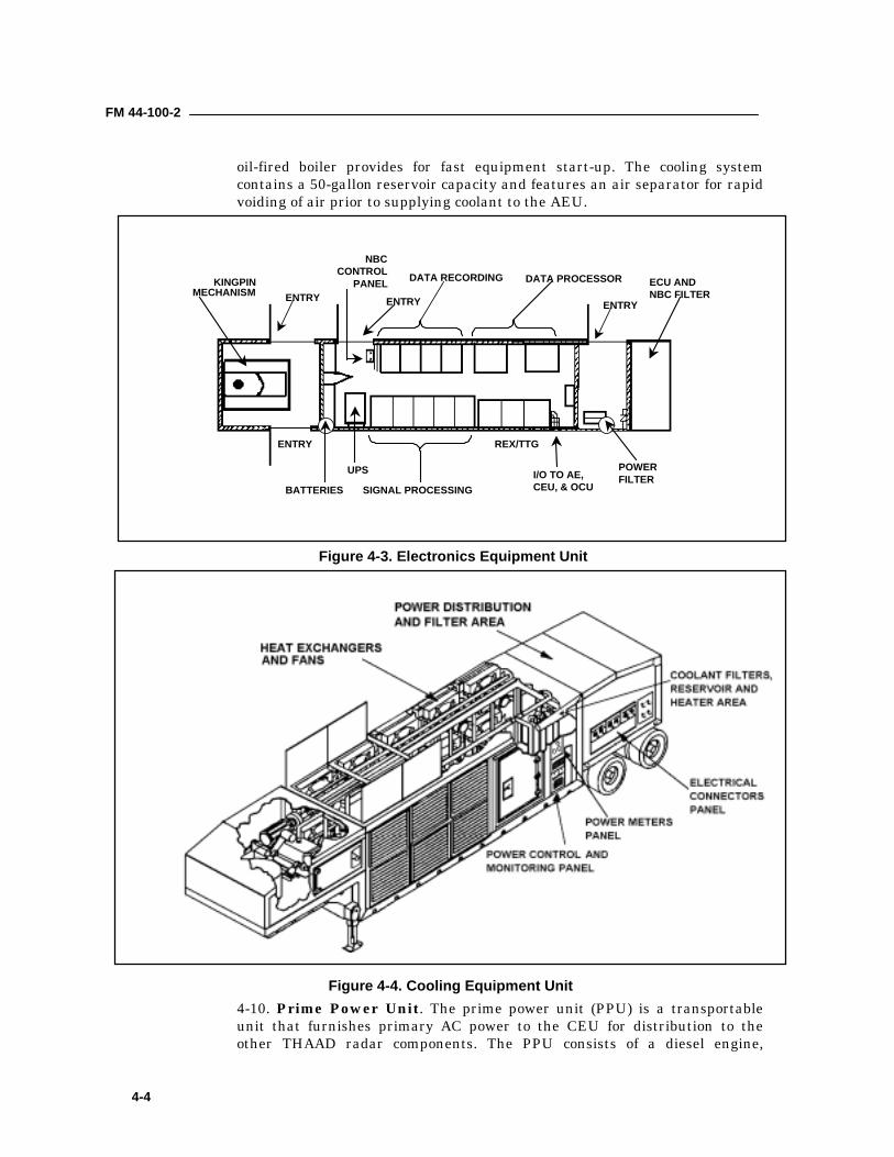
4-8. Electronics Equipment Unit. The electronics equipment unit (EEU) isan environmentally controlled shelter housing the electronic equipment usedto generate the timing and control signals required for radar operation andsignal processing. The EEU consists primarily of the receiver, recorders, andsignal processor and data processing equipment of the radar. All equipmentis enclosed in a trailer that is pulled by the M1088 Family of MediumTactical Vehicles or a commercial semi-tractor with a kingpin adapter, andtransported by C-141 and larger aircraft. The trailer includes anenvironmental control unit and an NBC vestibule and filter. The trailer hasair-ride suspension on the main dolly set and the kingpin mechanism (figure4-3, page 4-4).4-9. Cooling Equipment Unit. The Cooling Equipment Unit (CEU) (figure4-4, page 4-4) provides liquid cooling required for the AEU. It is equippedwith a power distribution unit (PDU) which distributes the prime inputpower from the prime power unit (PPU) to the rest of the radar components.The trailer has an air-ride suspension on both the main dolly set and thekingpin mechanism. The coolant lines have quick disconnect fittings for rapidmarch order and emplacement. A status panel with alarm center providesstatus and warning of coolant overheating and fan failure. The CEU has lowcoolant pressure and coolant reservoir level indicators. A low temperature,
REAR MOBILIZER TRANSMIT/RECEIVE ELEMENT ASSEMBLIESBEAM STEERING GENERATOR
LEVELING JACKSRADOME
FRONT MOBILIZER
Figure 4-2. THAAD Antenna Equipment Unit
FM 44-100-2
4-4
oil-fired boiler provides for fast equipment start-up. The cooling systemcontains a 50-gallon reservoir capacity and features an air separator for rapidvoiding of air prior to supplying coolant to the AEU.
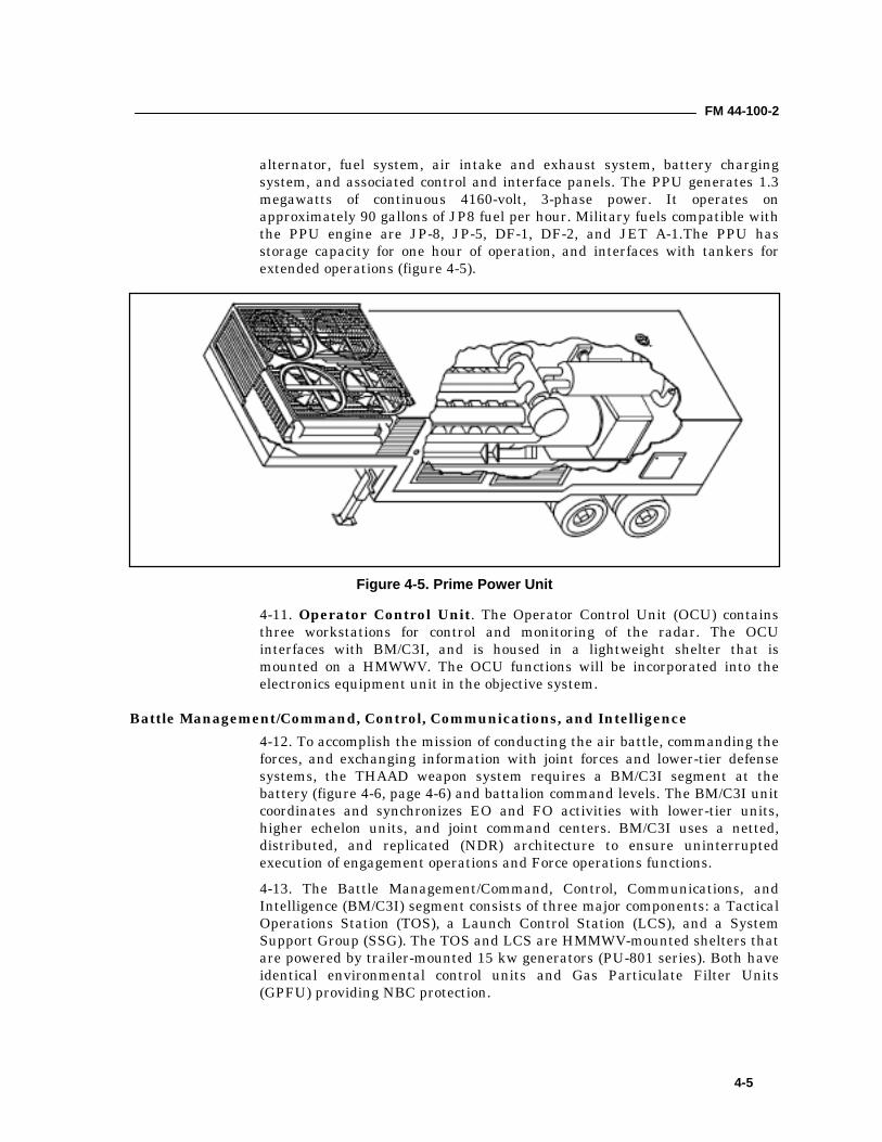
4-10. Prime Power Unit. The prime power unit (PPU) is a transportableunit that furnishes primary AC power to the CEU for distribution to theother THAAD radar components. The PPU consists of a diesel engine,
KINGPINMECHANISM
NBCCONTROL
PANEL DATA RECORDING DATA PROCESSOR
ENTRYENTRY
ENTRY
SIGNAL PROCESSING
REX/TTG
I/O TO AE,CEU, & OCU
POWERFILTER
ECU ANDNBC FILTER
BATTERIES
UPS
ENTRY
Figure 4-3. Electronics Equipment Unit
Figure 4-4. Cooling Equipment Unit
FM 44-100-2
4-5
alternator, fuel system, air intake and exhaust system, battery chargingsystem, and associated control and interface panels. The PPU generates 1.3megawatts of continuous 4160-volt, 3-phase power. It operates onapproximately 90 gallons of JP8 fuel per hour. Military fuels compatible withthe PPU engine are JP-8, JP-5, DF-1, DF-2, and JET A-1.The PPU hasstorage capacity for one hour of operation, and interfaces with tankers forextended operations (figure 4-5).
4-11. Operator Control Unit. The Operator Control Unit (OCU) containsthree workstations for control and monitoring of the radar. The OCUinterfaces with BM/C3I, and is housed in a lightweight shelter that ismounted on a HMWWV. The OCU functions will be incorporated into theelectronics equipment unit in the objective system.
Battle Management/Command, Control, Communications, and Intelligence4-12. To accomplish the mission of conducting the air battle, commanding theforces, and exchanging information with joint forces and lower-tier defensesystems, the THAAD weapon system requires a BM/C3I segment at thebattery (figure 4-6, page 4-6) and battalion command levels. The BM/C3I unitcoordinates and synchronizes EO and FO activities with lower-tier units,higher echelon units, and joint command centers. BM/C3I uses a netted,distributed, and replicated (NDR) architecture to ensure uninterruptedexecution of engagement operations and Force operations functions.4-13. The Battle Management/Command, Control, Communications, andIntelligence (BM/C3I) segment consists of three major components: a TacticalOperations Station (TOS), a Launch Control Station (LCS), and a SystemSupport Group (SSG). The TOS and LCS are HMMWV-mounted shelters thatare powered by trailer-mounted 15 kw generators (PU-801 series). Both haveidentical environmental control units and Gas Particulate Filter Units(GPFU) providing NBC protection.
Figure 4-5. Prime Power Unit
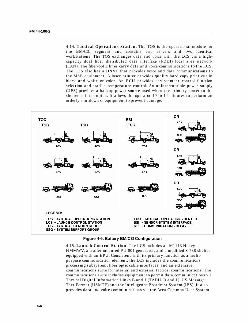
FM 44-100-2
4-6
4-14. Tactical Operations Station. The TOS is the operational module forthe BM/C3I segment and contains two servers and two identicalworkstations. The TOS exchanges data and voice with the LCS via a high-capacity dual fiber distributed data interface (FDDI) local area network(LAN). The fiber-optic lines carry data and voice communications to the LCS.The TOS also has a DNVT that provides voice and data communications tothe MSE equipment. A laser printer provides quality hard copy print out inblack and white or color. An ECU provides environment control functionselection and station temperature control. An uninterruptible power supply(UPS) provides a backup power source used when the primary power to theshelter is interrupted. It allows the operator 10 to 14 minutes to perform anorderly shutdown of equipment to prevent damage.
4-15. Launch Control Station. The LCS includes an M1113 HeavyHMMWV, a trailer mounted PU-801 generator, and a modified S-788 shelterequipped with an EPU. Consistent with its primary function as a multi-purpose communication element, the LCS includes the communicationsprocessing subsystem, fiber optic cable interfaces, and an extensivecommunications suite for internal and external tactical communications. Thecommunications suite includes equipment to permit data communications viaTactical Digital Information Links B and J (TADIL B and J), US MessageText Format (USMTF) and the Intelligence Broadcast System (IBS). It alsoprovides data and voice communications via the Area Common User System
LEGEND:
Figure 4-6. Battery BM/C3I Configuration
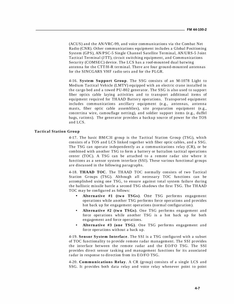
FM 44-100-2
4-7
(ACUS) and the AN/VRC-99, and voice communications via the Combat NetRadio (CNR). Other communications equipment includes a Global PositioningSystem (GPS), AN/PSC-5 Single Channel Satellite Terminal, AN/URS-5 JointTactical Terminal (JTT), circuit switching equipment, and CommunicationsSecurity (COMSEC) device. The LCS has a roof-mounted dual batwingantenna for the CTT/H-R terminal. There are four ground-mounted antennasfor the SINCGARS VHF radio sets and for the PLGR.
4-16. System Support Group. The SSG consists of an M-1078 Light toMedium Tactical Vehicle (LMTV) equipped with an electric crane installed inthe cargo bed and a towed PU-802 generator. The SSG is also used to supportfiber optics cable laying activities and to transport additional items ofequipment required for THAAD Battery operations. Transported equipmentincludes communications ancillary equipment (e.g., antennas, antennamasts, fiber optic cable assemblies), site preparation equipment (e.g.,concertina wire, camouflage netting), and soldier support items (e.g., duffelbags, rations). The generator provides a backup source of power for the TOSand LCS.
Tactical Station Group4-17. The basic BM/C3I group is the Tactical Station Group (TSG), whichconsists of a TOS and LCS linked together with fiber optic cables, and a SSG.The TSG can operate independently as a communications relay (CR), or becombined with another TSG to form a battery or battalion tactical operationscenter (TOC). A TSG can be attached to a remote radar site where itfunctions as a sensor system interface (SSI). These various functional groupsare discussed in the following paragraphs.4-18. THAAD TOC. The THAAD TOC normally consists of two TacticalStation Groups (TSG). Although all necessary TOC functions can beaccomplished using one TSG, to ensure against total system failure duringthe ballistic missile battle a second TSG shadows the first TSG. The THAADTOC may be configured as follows:
• Alternative #1 (two TSGs). One TSG performs engagementoperations while another TSG performs force operations and provideshot back up for engagement operations (normal configuration).
• Alternative #2 (two TSGs). One TSG performs engagement andforce operations while another TSG is a hot back up for bothengagement and force operations.
• Alternative #3 (one TSG). One TSG performs engagement andforce operations without a back up.
4-19. Sensor System Interface. The SSI is a TSG configured with a subsetof TOC functionality to provide remote radar management. The SSI providesthe interface between the remote radar and the EO/FO TSG. The SSIprovides direct sensor tasking and management functions for its associatedradar in response to direction from its EO/FO TSG.4-20. Communications Relay. A CR (group) consists of a single LCS andSSG. It provides both data relay and voice relay whenever point to point
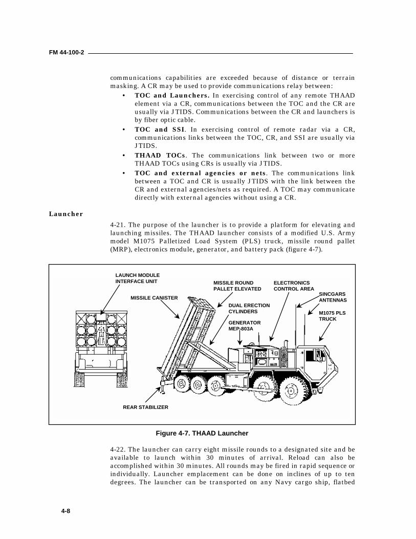
FM 44-100-2
4-8
communications capabilities are exceeded because of distance or terrainmasking. A CR may be used to provide communications relay between:
• TOC and Launchers. In exercising control of any remote THAADelement via a CR, communications between the TOC and the CR areusually via JTIDS. Communications between the CR and launchers isby fiber optic cable.
• TOC and SSI. In exercising control of remote radar via a CR,communications links between the TOC, CR, and SSI are usually viaJTIDS.
• THAAD TOCs. The communications link between two or moreTHAAD TOCs using CRs is usually via JTIDS.
• TOC and external agencies or nets. The communications linkbetween a TOC and CR is usually JTIDS with the link between theCR and external agencies/nets as required. A TOC may communicatedirectly with external agencies without using a CR.
Launcher4-21. The purpose of the launcher is to provide a platform for elevating andlaunching missiles. The THAAD launcher consists of a modified U.S. Armymodel M1075 Palletized Load System (PLS) truck, missile round pallet(MRP), electronics module, generator, and battery pack (figure 4-7).
4-22. The launcher can carry eight missile rounds to a designated site and beavailable to launch within 30 minutes of arrival. Reload can also beaccomplished within 30 minutes. All rounds may be fired in rapid sequence orindividually. Launcher emplacement can be done on inclines of up to tendegrees. The launcher can be transported on any Navy cargo ship, flatbed
LAUNCH MODULEINTERFACE UNIT
MISSILE CANISTER
MISSILE ROUNDPALLET ELEVATED
DUAL ERECTIONCYLINDERS
ELECTRONICSCONTROL AREA
M1075 PLSTRUCK
REAR STABILIZER
GENERATORMEP-803A
SINCGARSANTENNAS
Figure 4-7. THAAD Launcher
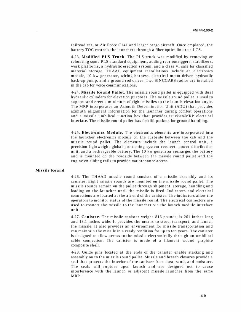
FM 44-100-2
4-9
railroad car, or Air Force C141 and larger cargo aircraft. Once emplaced, thebattery TOC controls the launchers through a fiber optics link to a LCS.4-23. Modified PLS Truck. The PLS truck was modified by removing orrelocating some PLS standard equipment, adding rear outriggers, stabilizers,work platforms, a hydraulic erection system, and a class VI safe for classifiedmaterial storage. THAAD equipment installations include an electronicsmodule, 10 kw generator, wiring harness, electrical motor-driven hydraulicback-up pump, and a ground rod driver. Two SINCGARS radios are installedin the cab for voice communications.4-24. Missile Round Pallet. The missile round pallet is equipped with dualhydraulic cylinders for elevation purposes. The missile round pallet is used tosupport and erect a minimum of eight missiles to the launch elevation angle.The MRP incorporates an Azimuth Determination Unit (ADU) that providesazimuth alignment information for the launcher during combat operationsand a missile umbilical junction box that provides truck-to-MRP electricalinterface. The missile round pallet has forklift pockets for ground handling.
4-25. Electronics Module. The electronics elements are incorporated intothe launcher electronics module on the curbside between the cab and themissile round pallet. The elements include the launch control unit, aprecision lightweight global positioning system receiver, power distributionunit, and a rechargeable battery. The 10 kw generator recharges the batteryand is mounted on the roadside between the missile round pallet and theengine on sliding rails to provide maintenance access.
Missile Round4-26. The THAAD missile round consists of a missile assembly and itscanister. Eight missile rounds are mounted on the missile round pallet. Themissile rounds remain on the pallet through shipment, storage, handling andloading on the launcher until the missile is fired. Indicators and electricalconnections are located at the aft end of the canister. The indicators allow theoperators to monitor status of the missile round. The electrical connectors areused to connect the missile to the launcher via the launch module interfaceunit.4-27. Canister. The missile canister weighs 816 pounds, is 261 inches longand 18.1 inches wide. It provides the means to store, transport, and launchthe missile. It also provides an environment for missile transportation andcan maintain the missile in a ready condition for up to ten years. The canisteris designed to allow access to the missile electronically through an umbilicalcable connection. The canister is made of a filament wound graphitecomposite shell.4-28. Guide pins located at the ends of the canister enable stacking andassembly on to the missile round pallet. Muzzle and breech closures provide aseal that protects the interior of the canister from dust, sand, and moisture.The seals will rupture upon launch and are designed not to causeinterference with the launch or adjacent missile launches from the sameMRP.
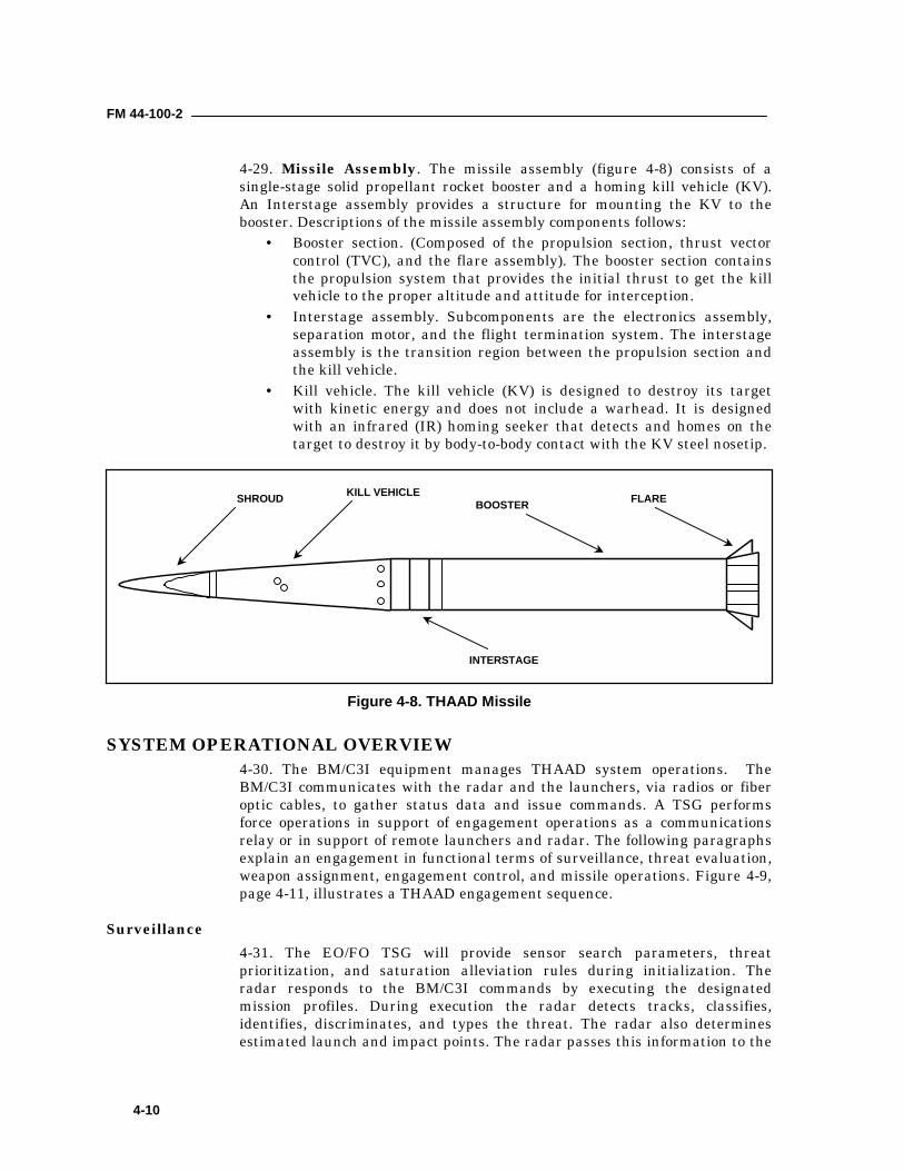
FM 44-100-2
4-10
4-29. Missile Assembly. The missile assembly (figure 4-8) consists of asingle-stage solid propellant rocket booster and a homing kill vehicle (KV).An Interstage assembly provides a structure for mounting the KV to thebooster. Descriptions of the missile assembly components follows:
• Booster section. (Composed of the propulsion section, thrust vectorcontrol (TVC), and the flare assembly). The booster section containsthe propulsion system that provides the initial thrust to get the killvehicle to the proper altitude and attitude for interception.
• Interstage assembly. Subcomponents are the electronics assembly,separation motor, and the flight termination system. The interstageassembly is the transition region between the propulsion section andthe kill vehicle.
• Kill vehicle. The kill vehicle (KV) is designed to destroy its targetwith kinetic energy and does not include a warhead. It is designedwith an infrared (IR) homing seeker that detects and homes on thetarget to destroy it by body-to-body contact with the KV steel nosetip.
SYSTEM OPERATIONAL OVERVIEW4-30. The BM/C3I equipment manages THAAD system operations. TheBM/C3I communicates with the radar and the launchers, via radios or fiberoptic cables, to gather status data and issue commands. A TSG performsforce operations in support of engagement operations as a communicationsrelay or in support of remote launchers and radar. The following paragraphsexplain an engagement in functional terms of surveillance, threat evaluation,weapon assignment, engagement control, and missile operations. Figure 4-9,page 4-11, illustrates a THAAD engagement sequence.
Surveillance4-31. The EO/FO TSG will provide sensor search parameters, threatprioritization, and saturation alleviation rules during initialization. Theradar responds to the BM/C3I commands by executing the designatedmission profiles. During execution the radar detects tracks, classifies,identifies, discriminates, and types the threat. The radar also determinesestimated launch and impact points. The radar passes this information to the
SHROUD BOOSTER FLAREKILL VEHICLE
INTERSTAGE
Figure 4-8. THAAD Missile
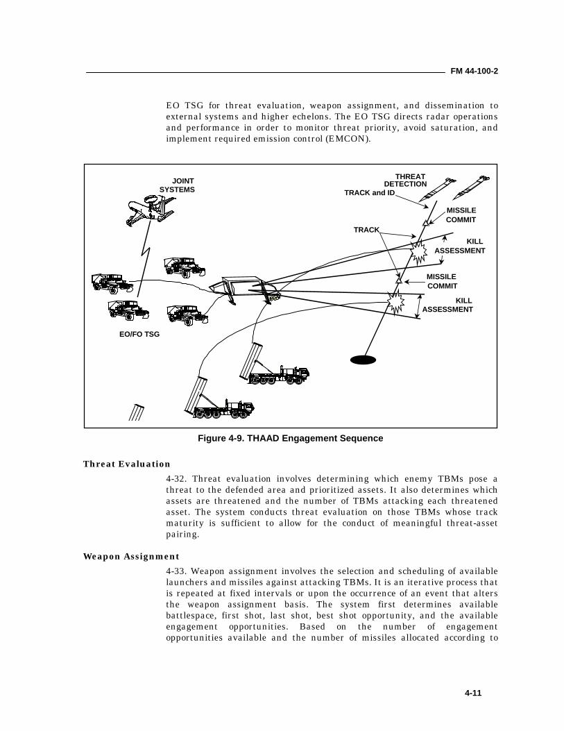
FM 44-100-2
4-11
EO TSG for threat evaluation, weapon assignment, and dissemination toexternal systems and higher echelons. The EO TSG directs radar operationsand performance in order to monitor threat priority, avoid saturation, andimplement required emission control (EMCON).
Threat Evaluation4-32. Threat evaluation involves determining which enemy TBMs pose athreat to the defended area and prioritized assets. It also determines whichassets are threatened and the number of TBMs attacking each threatenedasset. The system conducts threat evaluation on those TBMs whose trackmaturity is sufficient to allow for the conduct of meaningful threat-assetpairing.
Weapon Assignment4-33. Weapon assignment involves the selection and scheduling of availablelaunchers and missiles against attacking TBMs. It is an iterative process thatis repeated at fixed intervals or upon the occurrence of an event that altersthe weapon assignment basis. The system first determines availablebattlespace, first shot, last shot, best shot opportunity, and the availableengagement opportunities. Based on the number of engagementopportunities available and the number of missiles allocated according to
THREATDETECTION
TRACK and ID
MISSILECOMMIT
MISSILECOMMIT
KILLASSESSMENT
KILLASSESSMENT
TRACK
JOINTSYSTEMS
EO/FO TSG
Figure 4-9. THAAD Engagement Sequence
FM 44-100-2
4-12
defense objectives, the system selects a method of fire. The system uses shoot-look-shoot as the method of fire where feasible.4-34. The system examines launcher-target combinations with a view towardselecting intercept points that maximize system effectiveness and schedulingintercepts so that the radar is not overloaded and scheduling launchers thatcan best support the engagement. The system plans subsequent shotopportunities for execution, if required. Based on the above, the systemselects for implementation the set of launcher-target schedules most nearlysatisfying the decision criteria. Launch time is predicated on achieving anintercept point location accuracy that is good enough to ensure that themissile possesses sufficient divert capacity and that the target will be in themissile seeker's acquisition field of view.
Engagement Control4-35. Engagement control involves determining the fire control solution andthose BM/C3I and radar functions associated with controlling theengagement through kills assessment and possible re-engagement. Aftermissile commit and prior to launch, the system determines the finaltrajectory, monitors launch and launch time, establishes the guidance andtrack update schedule, and schedules radar and communications supportresources. During missile flyout, the EO TSG determines guidance and targetinformation and transmits them to the missile through the radar. The radartracks the missile and target through intercept and provides kill assessmentdata to the EO TSG. In case of a miss, re-engagement is immediate,battlespace permitting. In case of a miss with an uncertain kill, the systemre-identifies the target and reinitiates the threat evaluation and weaponassignment processes and is reengaged if battlespace permits.
Missile Operations4-36. The following paragraphs summarizes the major actions from the timethe EO TSG determines engagement solutions up to destruction of a targetby the kill vehicle (KV) with kinetic energy.4-37. Prelaunch. The EO TSG determines the engagement solution andpairs the target with the launcher. It schedules the launch. It also providestrajectory parameters to the radar and launcher, which update the radar,and initializes the missile via the launcher. The missile performs built-in-tests in response to the EO TSG command and relays results back to the EOTSG via the launcher.4-38. Launch. The EO TSG sends the fire command to the missile via thelauncher. The missile booster ignites. The launcher then provides the EOTSG the exact time of launch.4-39. Boost. The booster section contains the propulsion system thatprovides the initial thrust to get the kill vehicle to the proper altitude andattitude for interception. The booster section has two sub-components: thepropulsion section and the thrust vector control (TVC). The EO TSG updatesactual time of launch and sends it to the radar. The radar provides boostphase update to the in-flight missile. The missile then deploys the boosterflares.
FM 44-100-2
4-13
4-40. Postboost. The EO TSG provides in-flight target and missile statusupdate to the missile via the radar. The booster then separates. The radarprovides the EO TSG with the kill vehicle (KV) and target status.4-41. Midcourse. The EO TSG provides in-flight target update to the KV viathe radar. A divert and attitude control system (DACS) provides the KV withangle of attack and roll control. The KV has a self-contained cooling systemthat cools the seeker when in the IR operation. Seeker cool down begins priorto acquisition.4-42. Hand-over and Acquisition. The EO TSG provides final in-flighttarget update and target object map (TOM) to the KV via the radar. TheTOM is designed to display object details and includes range, altitude, speed,and threat class. The shroud separates from the KV. The seeker beginsacquisition mode. The KV matches the seeker scene against the TOM. TheKV designates the target and initiates a track file.4-43. Target Track. The KV downlinks processed homing data. The KVsteers to aimpoint based on radar estimates and the thrusters’ control of theKV attitude.4-44. Engage. The KV resolves the target image and determines the finalaimpoint. The KV diverts to intercept and downlinks homing data.4-45. Impact and Target Destruction. The KV hits the target withtremendous kinetic energy to destroy the TBM. The radar updates the EOTSG data and then conducts kill assessment.
Communications Equipment4-46. Many different types of communications equipment is organic to theTHAAD battery. Each has different characteristics and multiple potentialuses. These items consist of radio terminal sets, telephone sets, andcommunications processors. Together they makeup the heart of the THAADcommunications system and are described in the following paragraphs.4-47. AN/GRC-193A Radio. The AN/GRC-193A is a long-haul EO HEUsecondary radio communication network which supports the air defensecoordination net (ADCN).4-48. AN/GRC-226 Radio. The AN/GRC-226 UHF (band 3 only), 15 channelradio operates in the 225 – 400 MHz band. This radio is compatible withradios used in the ACUS network. Two AN/GRC-226 radios are installed ineach LCS. The radio provides line-of-sight communications for both voice anddata. This is a bulk (trunk) encrypted communications link containingmultiplexed voice and data circuits. Each set is comprised of a receiver-transmitter, a baseband assembly, and an antenna assembly.4-49. AN/GSQ-240 JTIDS Class 2M Radio. The JTIDS provides a jamresistant ground-to-air and ground-to-ground data communications. JTIDS isa high-speed data radio that operates in a time-shared data networkproviding access to theater EO surveillance and targeting informationnetwork via a time division multiple access (TDMA) architecture in the 960MHz to 1215 MHz frequency range. Within the battery, JTIDS supports theEO data communications between the EO TSG and the SSI. The JTIDS
FM 44-100-2
4-14
terminal, with omnidirectional antenna and telescoping mast makes upJTIDS. The JTIDS may be initialized through any one of the TOS or LCSworkstations.4-50. Commander’s Tactical Terminal. The CTT is a hybrid two-channelreceiver that operates within the 225 MHz to 1.4 GHz UHF frequency range.It provides access to a TIBS intelligence network via either LOS or satellitebroadcasts. This terminal is interfaced to a laptop computer that providesTHAAD access to intelligence information at theater and national levels. TheCTT utilizes the LCS roof mounted dual batwing antenna.4-51. Compact Digital Switch. The Compact Digital Switch (CDS [ON-422]) is the heart of the THAAD’s communication capabilities. It can handleover 708 individual circuits (THAAD requires less than its capability). Thisdevice routes telephone and data throughout the battery and the externalACUS network. Each LCS contains one CDS, which includes a multi-stationintercom system with selective answering capability, audible/visual alerts,and conference calling (intercom, radio, and telephone) capability. The twoassociated pieces of COMSEC equipment are the speech security equipmentand the trunk encryption devices that provide bulk encryption for ACUSpurposes. The software used to initialize the CDS is contained in a laptopcomputer. The software version of the CDS must also be compatible with thesoftware version used by the MSE system. Pre-affiliation lists (routing tables)and individual phone lists must also stay current to ensure maximuminteroperability.4-52. Encryption Devices. THAAD has two types of encryption for theACUS/MSE network. The first is a trunk encryption device (TED), KG-194A.This device performs trunk encryption (e.g. encrypts all the channels in thetrunk group) for external connectivity. There are two TEDs per LCS thatsupport the AN/GRC-226 radio and the CDS. They also support the two trunkcable connections (TG1 and TG2) located at the communication demarcationpanel. The second device is a KIV-7 that is also routed through the CDS. TheKIV-7 supports single channel TADIL B data link encryption. This data linkis used to exchange EO data with an Air Force CRC or a Marine TAOC.4-53. Fiber Optic Cable. Fiber optic communications consist of modulator-demodulator equipment connected by cables with four fiber optic strands tiedtogether to form cables capable of carrying data and voice. These cables are inone-kilometer increments. For the fiber optic cables a maximum distance oftwo kilometers may be used. The BMC3I, radar, LCS, and launcher sectionsall use the same cable type. At the BMC3I, radar and LCSs, the fiber opticcables are used to interconnect the TOS and LCS in any configuration. Theselocal area network (LAN) configurations are referred to as the fiber optic datadistribution interface (FDDI) system.4-54. Global Positioning System. Each major subsystem with the THAADbattery has a GPS. The GPS is used for location identification and timesynchronization across the battery. The GPS (PLGR) unit may also beremoved from the mounted location and used as a handheld receiver fornavigational purposes. However, prior to removing the GPS receiver from themounted location, the GPS must be inactivated from the THAAD tacticalsoftware to avoid system faults.
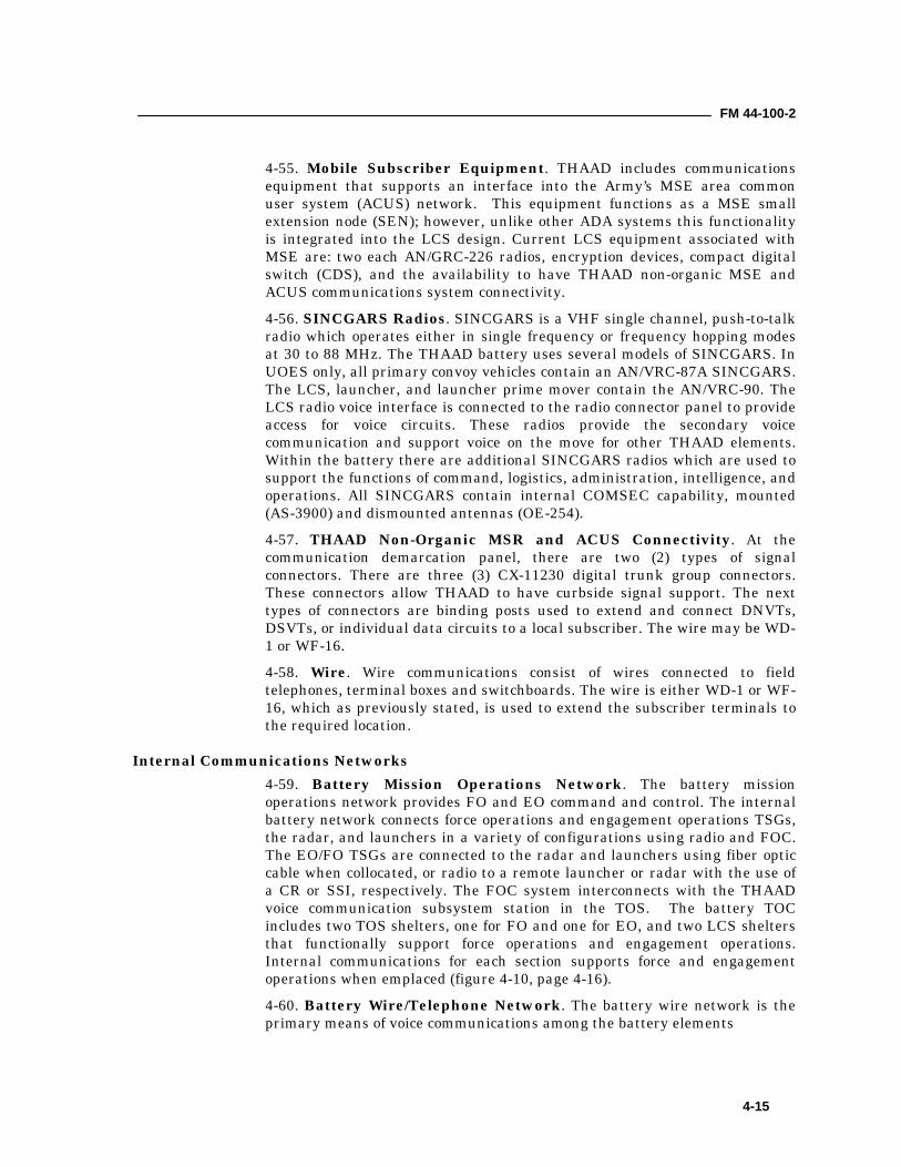
FM 44-100-2
4-15
4-55. Mobile Subscriber Equipment. THAAD includes communicationsequipment that supports an interface into the Army’s MSE area commonuser system (ACUS) network. This equipment functions as a MSE smallextension node (SEN); however, unlike other ADA systems this functionalityis integrated into the LCS design. Current LCS equipment associated withMSE are: two each AN/GRC-226 radios, encryption devices, compact digitalswitch (CDS), and the availability to have THAAD non-organic MSE andACUS communications system connectivity.4-56. SINCGARS Radios. SINCGARS is a VHF single channel, push-to-talkradio which operates either in single frequency or frequency hopping modesat 30 to 88 MHz. The THAAD battery uses several models of SINCGARS. InUOES only, all primary convoy vehicles contain an AN/VRC-87A SINCGARS.The LCS, launcher, and launcher prime mover contain the AN/VRC-90. TheLCS radio voice interface is connected to the radio connector panel to provideaccess for voice circuits. These radios provide the secondary voicecommunication and support voice on the move for other THAAD elements.Within the battery there are additional SINCGARS radios which are used tosupport the functions of command, logistics, administration, intelligence, andoperations. All SINCGARS contain internal COMSEC capability, mounted(AS-3900) and dismounted antennas (OE-254).4-57. THAAD Non-Organic MSR and ACUS Connectivity. At thecommunication demarcation panel, there are two (2) types of signalconnectors. There are three (3) CX-11230 digital trunk group connectors.These connectors allow THAAD to have curbside signal support. The nexttypes of connectors are binding posts used to extend and connect DNVTs,DSVTs, or individual data circuits to a local subscriber. The wire may be WD-1 or WF-16.4-58. Wire. Wire communications consist of wires connected to fieldtelephones, terminal boxes and switchboards. The wire is either WD-1 or WF-16, which as previously stated, is used to extend the subscriber terminals tothe required location.
Internal Communications Networks4-59. Battery Mission Operations Network. The battery missionoperations network provides FO and EO command and control. The internalbattery network connects force operations and engagement operations TSGs,the radar, and launchers in a variety of configurations using radio and FOC.The EO/FO TSGs are connected to the radar and launchers using fiber opticcable when collocated, or radio to a remote launcher or radar with the use ofa CR or SSI, respectively. The FOC system interconnects with the THAADvoice communication subsystem station in the TOS. The battery TOCincludes two TOS shelters, one for FO and one for EO, and two LCS sheltersthat functionally support force operations and engagement operations.Internal communications for each section supports force and engagementoperations when emplaced (figure 4-10, page 4-16).4-60. Battery Wire/Telephone Network. The battery wire network is theprimary means of voice communications among the battery elements
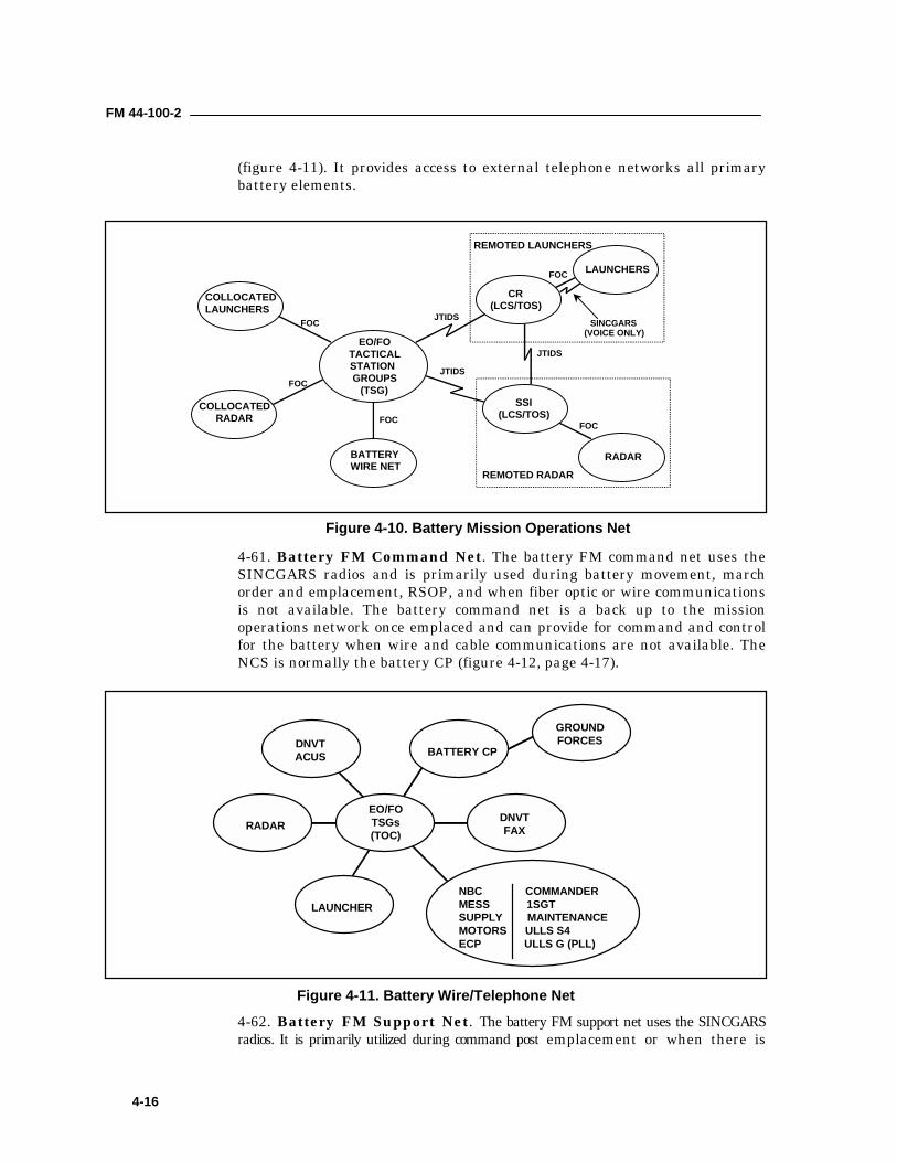
FM 44-100-2
4-16
(figure 4-11). It provides access to external telephone networks all primarybattery elements.
4-61. Battery FM Command Net. The battery FM command net uses theSINCGARS radios and is primarily used during battery movement, marchorder and emplacement, RSOP, and when fiber optic or wire communicationsis not available. The battery command net is a back up to the missionoperations network once emplaced and can provide for command and controlfor the battery when wire and cable communications are not available. TheNCS is normally the battery CP (figure 4-12, page 4-17).
4-62. Battery FM Support Net. The battery FM support net uses the SINCGARSradios. It is primarily utilized during command post emplacement or when there is
EO/FOTACTICALSTATIONGROUPS
(TSG)COLLOCATED
RADAR
COLLOCATEDLAUNCHERS
BATTERYWIRE NET
SSI(LCS/TOS)
LAUNCHERS
CR(LCS/TOS)
RADAR
FOC JTIDS
FOC
FOC FOC
FOC
JTIDS
JTIDS
SINCGARS(VOICE ONLY)
REMOTED LAUNCHERS
REMOTED RADAR
Figure 4-10. Battery Mission Operations Net
RADAR
LAUNCHER
BATTERY CPDNVTACUS
GROUNDFORCES
DNVTFAX
EO/FOTSGs(TOC)
NBC COMMANDERMESS 1SGTSUPPLY MAINTENANCEMOTORS ULLS S4ECP ULLS G (PLL)
Figure 4-11. Battery Wire/Telephone Net
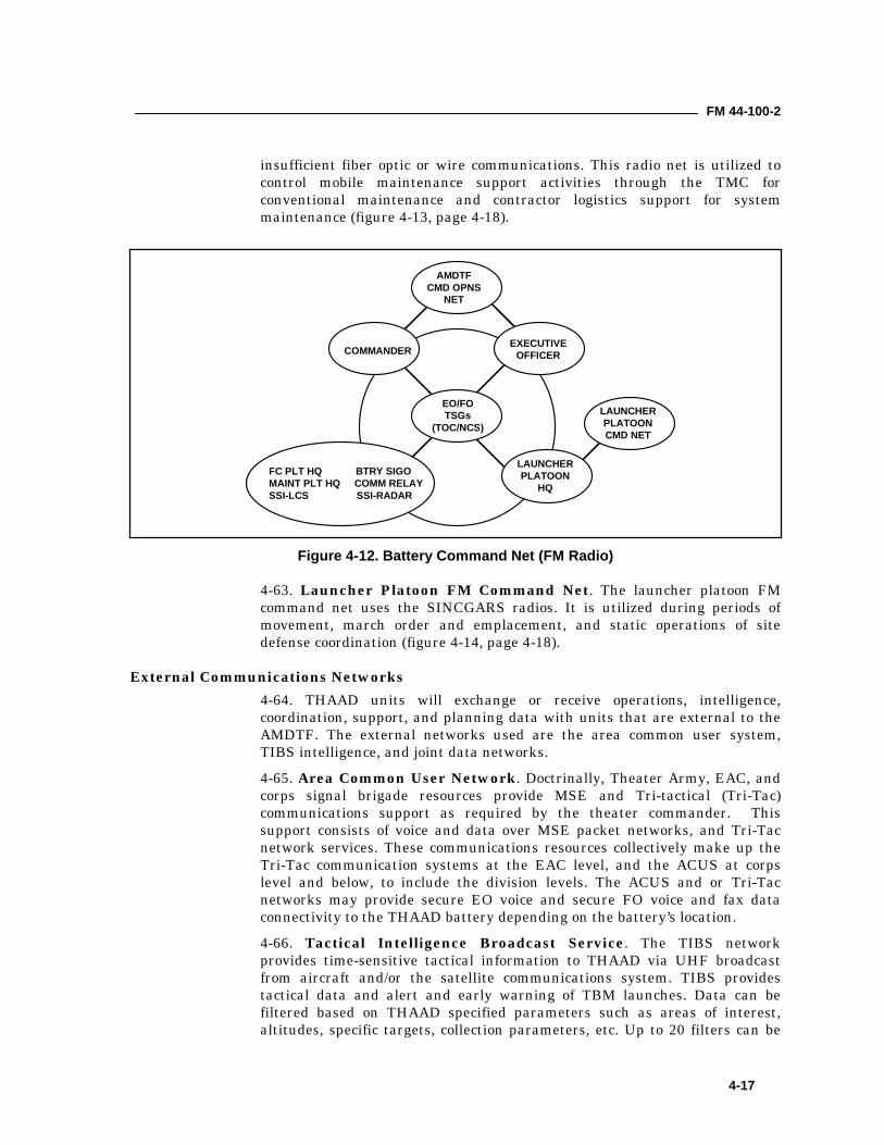
FM 44-100-2
4-17
insufficient fiber optic or wire communications. This radio net is utilized tocontrol mobile maintenance support activities through the TMC forconventional maintenance and contractor logistics support for systemmaintenance (figure 4-13, page 4-18).
4-63. Launcher Platoon FM Command Net. The launcher platoon FMcommand net uses the SINCGARS radios. It is utilized during periods ofmovement, march order and emplacement, and static operations of sitedefense coordination (figure 4-14, page 4-18).
External Communications Networks4-64. THAAD units will exchange or receive operations, intelligence,coordination, support, and planning data with units that are external to theAMDTF. The external networks used are the area common user system,TIBS intelligence, and joint data networks.4-65. Area Common User Network. Doctrinally, Theater Army, EAC, andcorps signal brigade resources provide MSE and Tri-tactical (Tri-Tac)communications support as required by the theater commander. Thissupport consists of voice and data over MSE packet networks, and Tri-Tacnetwork services. These communications resources collectively make up theTri-Tac communication systems at the EAC level, and the ACUS at corpslevel and below, to include the division levels. The ACUS and or Tri-Tacnetworks may provide secure EO voice and secure FO voice and fax dataconnectivity to the THAAD battery depending on the battery’s location.4-66. Tactical Intelligence Broadcast Service. The TIBS networkprovides time-sensitive tactical information to THAAD via UHF broadcastfrom aircraft and/or the satellite communications system. TIBS providestactical data and alert and early warning of TBM launches. Data can befiltered based on THAAD specified parameters such as areas of interest,altitudes, specific targets, collection parameters, etc. Up to 20 filters can be
EO/FOTSGs
(TOC/NCS)
COMMANDEREXECUTIVE
OFFICER
LAUNCHERPLATOON
HQ
AMDTFCMD OPNS
NET
LAUNCHERPLATOONCMD NET
FC PLT HQ BTRY SIGOMAINT PLT HQ COMM RELAYSSI-LCS SSI-RADAR
Figure 4-12. Battery Command Net (FM Radio)
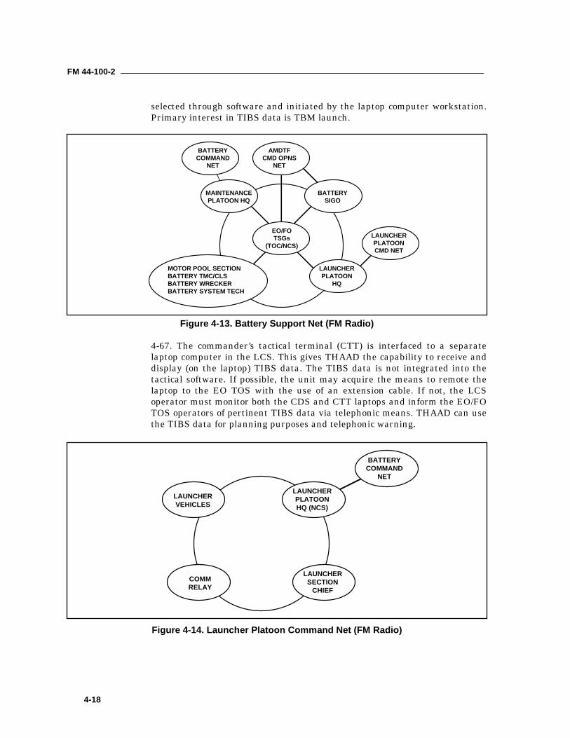
FM 44-100-2
4-18
selected through software and initiated by the laptop computer workstation.Primary interest in TIBS data is TBM launch.
4-67. The commander’s tactical terminal (CTT) is interfaced to a separatelaptop computer in the LCS. This gives THAAD the capability to receive anddisplay (on the laptop) TIBS data. The TIBS data is not integrated into thetactical software. If possible, the unit may acquire the means to remote thelaptop to the EO TOS with the use of an extension cable. If not, the LCSoperator must monitor both the CDS and CTT laptops and inform the EO/FOTOS operators of pertinent TIBS data via telephonic means. THAAD can usethe TIBS data for planning purposes and telephonic warning.
BATTERYCOMMAND
NET
LAUNCHERVEHICLES
LAUNCHERPLATOONHQ (NCS)
COMMRELAY
LAUNCHERSECTION
CHIEF
Figure 4-14. Launcher Platoon Command Net (FM Radio)
EO/FOTSGs
(TOC/NCS)
MAINTENANCEPLATOON HQ
BATTERYSIGO
LAUNCHERPLATOON
HQ
AMDTFCMD OPNS
NET
LAUNCHERPLATOONCMD NET
MOTOR POOL SECTIONBATTERY TMC/CLSBATTERY WRECKERBATTERY SYSTEM TECH
BATTERYCOMMAND
NET
Figure 4-13. Battery Support Net (FM Radio)

5-1
Chapter 5
Patriot Air Defense SystemThis chapter describes Patriot air defense system. This system is deployedto defend theater and corps commanders' assets.
MISSION5-1. The mission of Patriot is to provide protection for critical assets andmaneuver forces belonging to corps and echelons above corps (EAC) againstairborne threats from very low to very high altitudes. The objective of Patriotoperations at all levels is to disrupt and destroy the enemy's ability to mounteffective air operations.
SYSTEM DESCRIPTION – BATTALION FIRE DIRECTION CENTER5-2. The major end items of the Patriot battalion fire direction center (FDC)are the Information and Coordination Central (ICC) (AN/MSQ-ll6), ElectricPower Unit (EPU II) (PU 789), Communications Relay Group (CRG)(AN/MRC-137) and Antenna Mast Group (AMG) (OE-349/MRC).
Figure 5-1. Information and Coordination Central
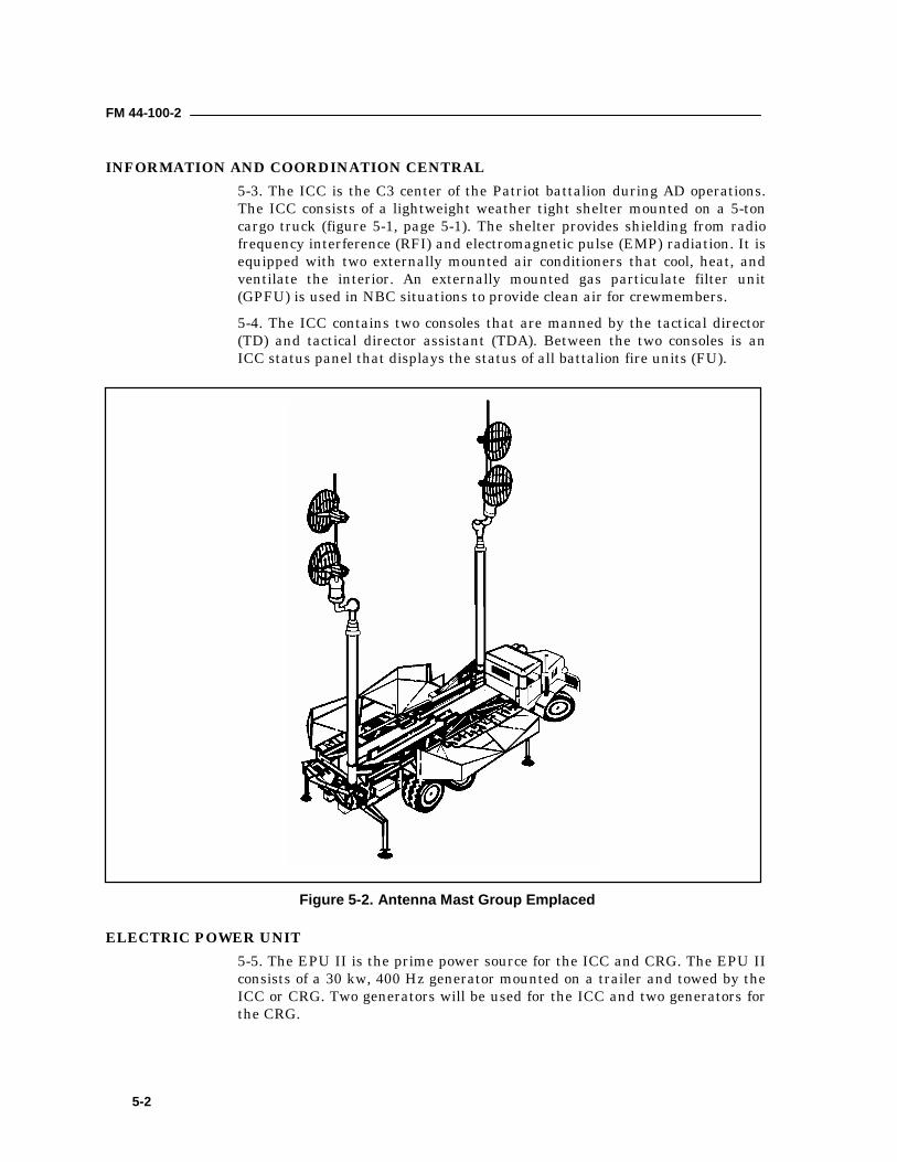
FM 44-100-2
5-2
INFORMATION AND COORDINATION CENTRAL5-3. The ICC is the C3 center of the Patriot battalion during AD operations.The ICC consists of a lightweight weather tight shelter mounted on a 5-toncargo truck (figure 5-1, page 5-1). The shelter provides shielding from radiofrequency interference (RFI) and electromagnetic pulse (EMP) radiation. It isequipped with two externally mounted air conditioners that cool, heat, andventilate the interior. An externally mounted gas particulate filter unit(GPFU) is used in NBC situations to provide clean air for crewmembers.5-4. The ICC contains two consoles that are manned by the tactical director(TD) and tactical director assistant (TDA). Between the two consoles is anICC status panel that displays the status of all battalion fire units (FU).
ELECTRIC POWER UNIT5-5. The EPU II is the prime power source for the ICC and CRG. The EPU IIconsists of a 30 kw, 400 Hz generator mounted on a trailer and towed by theICC or CRG. Two generators will be used for the ICC and two generators forthe CRG.
Figure 5-2. Antenna Mast Group Emplaced
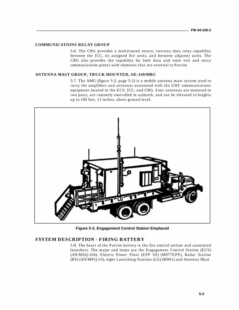
FM 44-100-2
5-3
COMMUNICATIONS RELAY GROUP5-6. The CRG provides a multirouted secure, two-way data relay capabilitybetween the ICC, its assigned fire units, and between adjacent units. TheCRG also provides the capability for both data and voice exit and entrycommunication points with elements that are external to Patriot.
ANTENNA MAST GROUP, TRUCK MOUNTED, OE-349/MRC5-7. The AMG (figure 5-2, page 5-2) is a mobile antenna mast system used tocarry the amplifiers and antennas associated with the UHF communicationsequipment located in the ECS, ICC, and CRG. Four antennas are mounted intwo pairs, are remotely controlled in azimuth, and can be elevated to heightsup to 100 feet, 11 inches, above ground level.
SYSTEM DESCRIPTION - FIRING BATTERY5-8. The heart of the Patriot battery is the fire control section and associatedlaunchers. The major end items are the Engagement Control Station (ECS)(AN/MSQ-104), Electric Power Plant (EPP III) (M977EPP), Radar Station(RS) (AN/MPQ-53), eight Launching Stations (LS) (M901) and Antenna Mast
Figure 5-3. Engagement Control Station Emplaced
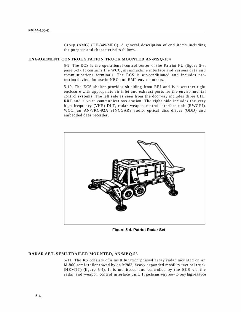
FM 44-100-2
5-4
Group (AMG) (OE-349/MRC). A general description of end items includingthe purpose and characteristics follows.
ENGAGEMENT CONTROL STATION TRUCK MOUNTED AN/MSQ-1045-9. The ECS is the operational control center of the Patriot FU (figure 5-3,page 5-3). It contains the WCC, man/machine interface and various data andcommunications terminals. The ECS is air-conditioned and includes pro-tection devices for use in NBC and EMP environments.5-10. The ECS shelter provides shielding from RFI and is a weather-tightenclosure with appropriate air inlet and exhaust ports for the environmentalcontrol systems. The left side as seen from the doorway includes three UHFRRT and a voice communications station. The right side includes the veryhigh frequency (VHF) DLT, radar weapon control interface unit (RWCIU),WCC, an AN/VRC-92A SINCGARS radio, optical disc drives (ODD) andembedded data recorder.
RADAR SET, SEMI-TRAILER MOUNTED, AN/MPQ-535-11. The RS consists of a multifunction phased array radar mounted on anM-860 semi-trailer towed by an M983, heavy expanded mobility tactical truck(HEMTT) (figure 5-4). It is monitored and controlled by the ECS via theradar and weapon control interface unit. It performs very low- to very high-altitude
Figure 5-4. Patriot Radar Set
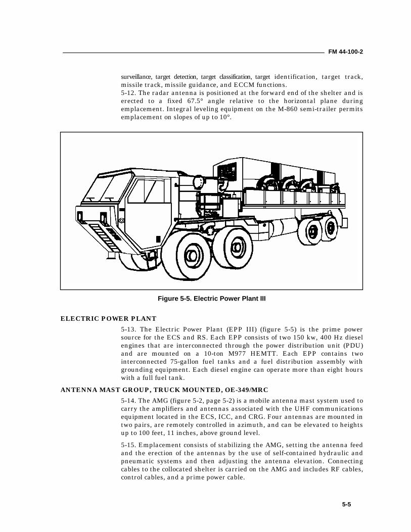
FM 44-100-2
5-5
surveillance, target detection, target classification, target identification, target track,missile track, missile guidance, and ECCM functions.5-12. The radar antenna is positioned at the forward end of the shelter and iserected to a fixed 67.5° angle relative to the horizontal plane duringemplacement. Integral leveling equipment on the M-860 semi-trailer permitsemplacement on slopes of up to 10°.
ELECTRIC POWER PLANT5-13. The Electric Power Plant (EPP III) (figure 5-5) is the prime powersource for the ECS and RS. Each EPP consists of two 150 kw, 400 Hz dieselengines that are interconnected through the power distribution unit (PDU)and are mounted on a 10-ton M977 HEMTT. Each EPP contains twointerconnected 75-gallon fuel tanks and a fuel distribution assembly withgrounding equipment. Each diesel engine can operate more than eight hourswith a full fuel tank.
ANTENNA MAST GROUP, TRUCK MOUNTED, OE-349/MRC5-14. The AMG (figure 5-2, page 5-2) is a mobile antenna mast system used tocarry the amplifiers and antennas associated with the UHF communicationsequipment located in the ECS, ICC, and CRG. Four antennas are mounted intwo pairs, are remotely controlled in azimuth, and can be elevated to heightsup to 100 feet, 11 inches, above ground level.5-15. Emplacement consists of stabilizing the AMG, setting the antenna feedand the erection of the antennas by the use of self-contained hydraulic andpneumatic systems and then adjusting the antenna elevation. Connectingcables to the collocated shelter is carried on the AMG and includes RF cables,control cables, and a prime power cable.
Figure 5-5. Electric Power Plant III
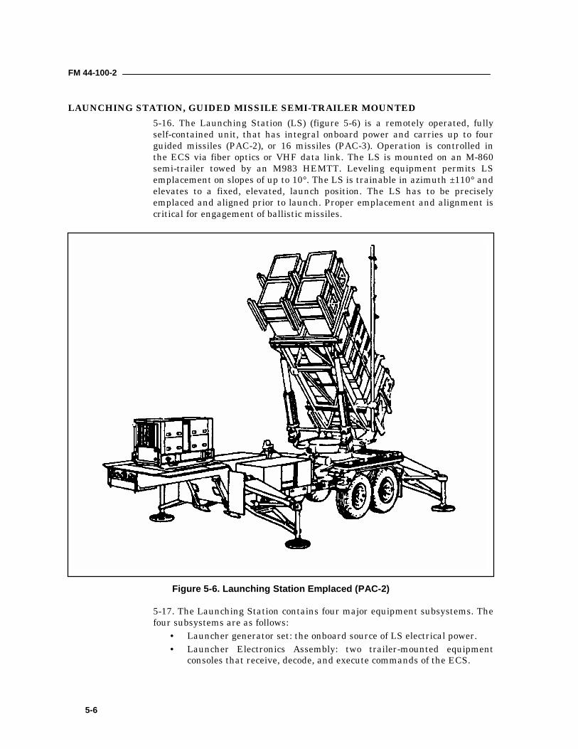
FM 44-100-2
5-6
LAUNCHING STATION, GUIDED MISSILE SEMI-TRAILER MOUNTED5-16. The Launching Station (LS) (figure 5-6) is a remotely operated, fullyself-contained unit, that has integral onboard power and carries up to fourguided missiles (PAC-2), or 16 missiles (PAC-3). Operation is controlled inthe ECS via fiber optics or VHF data link. The LS is mounted on an M-860semi-trailer towed by an M983 HEMTT. Leveling equipment permits LSemplacement on slopes of up to 10°. The LS is trainable in azimuth ±110° andelevates to a fixed, elevated, launch position. The LS has to be preciselyemplaced and aligned prior to launch. Proper emplacement and alignment iscritical for engagement of ballistic missiles.
5-17. The Launching Station contains four major equipment subsystems. Thefour subsystems are as follows:
• Launcher generator set: the onboard source of LS electrical power.• Launcher Electronics Assembly: two trailer-mounted equipment
consoles that receive, decode, and execute commands of the ECS.
Figure 5-6. Launching Station Emplaced (PAC-2)
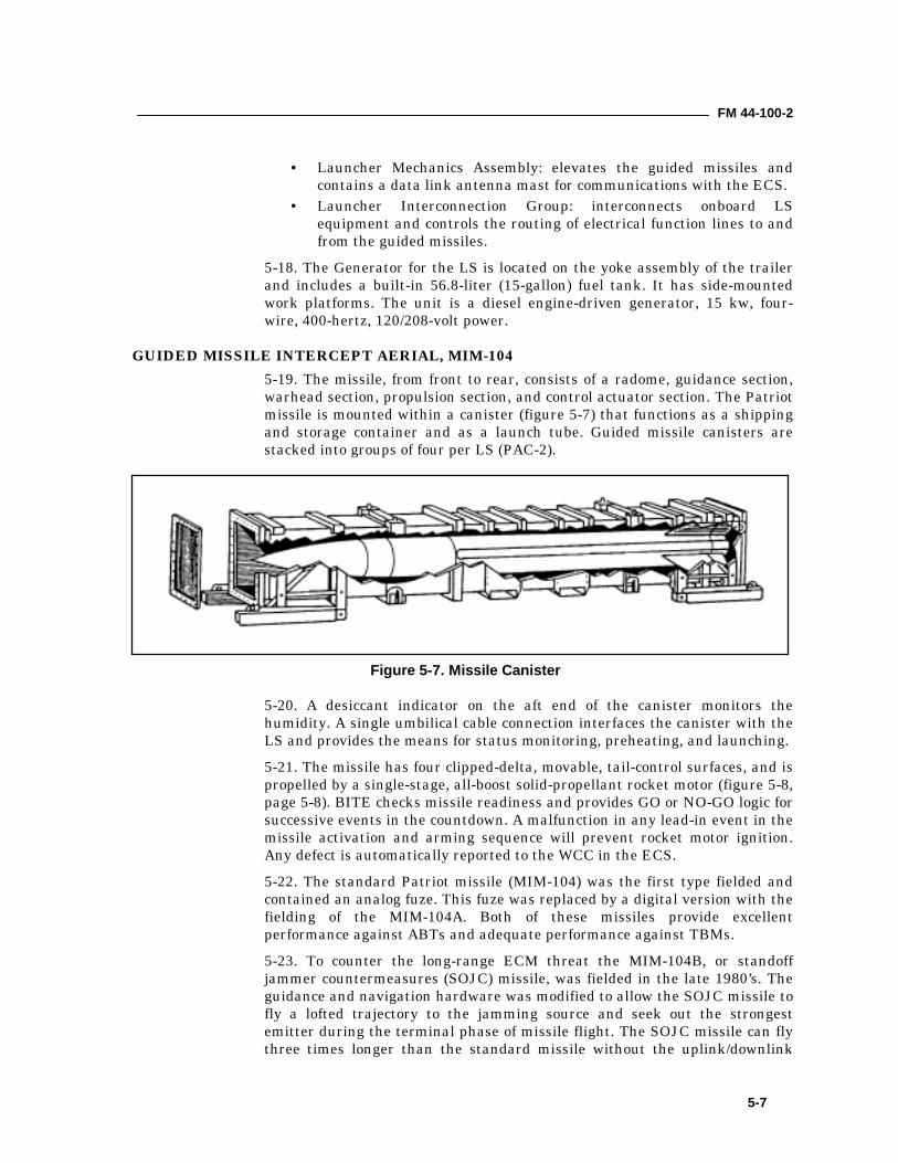
FM 44-100-2
5-7
• Launcher Mechanics Assembly: elevates the guided missiles andcontains a data link antenna mast for communications with the ECS.
• Launcher Interconnection Group: interconnects onboard LSequipment and controls the routing of electrical function lines to andfrom the guided missiles.
5-18. The Generator for the LS is located on the yoke assembly of the trailerand includes a built-in 56.8-liter (15-gallon) fuel tank. It has side-mountedwork platforms. The unit is a diesel engine-driven generator, 15 kw, four-wire, 400-hertz, 120/208-volt power.
GUIDED MISSILE INTERCEPT AERIAL, MIM-1045-19. The missile, from front to rear, consists of a radome, guidance section,warhead section, propulsion section, and control actuator section. The Patriotmissile is mounted within a canister (figure 5-7) that functions as a shippingand storage container and as a launch tube. Guided missile canisters arestacked into groups of four per LS (PAC-2).
5-20. A desiccant indicator on the aft end of the canister monitors thehumidity. A single umbilical cable connection interfaces the canister with theLS and provides the means for status monitoring, preheating, and launching.5-21. The missile has four clipped-delta, movable, tail-control surfaces, and ispropelled by a single-stage, all-boost solid-propellant rocket motor (figure 5-8,page 5-8). BITE checks missile readiness and provides GO or NO-GO logic forsuccessive events in the countdown. A malfunction in any lead-in event in themissile activation and arming sequence will prevent rocket motor ignition.Any defect is automatically reported to the WCC in the ECS.5-22. The standard Patriot missile (MIM-104) was the first type fielded andcontained an analog fuze. This fuze was replaced by a digital version with thefielding of the MIM-104A. Both of these missiles provide excellentperformance against ABTs and adequate performance against TBMs.5-23. To counter the long-range ECM threat the MIM-104B, or standoffjammer countermeasures (SOJC) missile, was fielded in the late 1980’s. Theguidance and navigation hardware was modified to allow the SOJC missile tofly a lofted trajectory to the jamming source and seek out the strongestemitter during the terminal phase of missile flight. The SOJC missile can flythree times longer than the standard missile without the uplink/downlink
Figure 5-7. Missile Canister
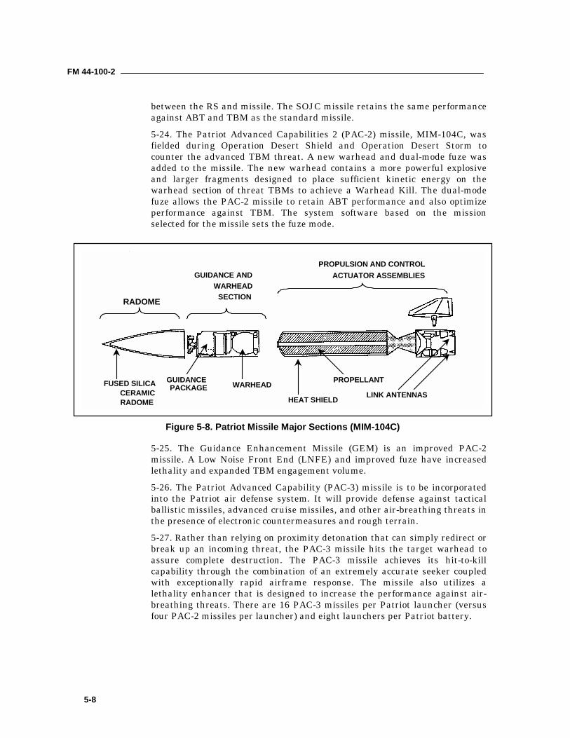
FM 44-100-2
5-8
between the RS and missile. The SOJC missile retains the same performanceagainst ABT and TBM as the standard missile.5-24. The Patriot Advanced Capabilities 2 (PAC-2) missile, MIM-104C, wasfielded during Operation Desert Shield and Operation Desert Storm tocounter the advanced TBM threat. A new warhead and dual-mode fuze wasadded to the missile. The new warhead contains a more powerful explosiveand larger fragments designed to place sufficient kinetic energy on thewarhead section of threat TBMs to achieve a Warhead Kill. The dual-modefuze allows the PAC-2 missile to retain ABT performance and also optimizeperformance against TBM. The system software based on the missionselected for the missile sets the fuze mode.
5-25. The Guidance Enhancement Missile (GEM) is an improved PAC-2missile. A Low Noise Front End (LNFE) and improved fuze have increasedlethality and expanded TBM engagement volume.5-26. The Patriot Advanced Capability (PAC-3) missile is to be incorporatedinto the Patriot air defense system. It will provide defense against tacticalballistic missiles, advanced cruise missiles, and other air-breathing threats inthe presence of electronic countermeasures and rough terrain.5-27. Rather than relying on proximity detonation that can simply redirect orbreak up an incoming threat, the PAC-3 missile hits the target warhead toassure complete destruction. The PAC-3 missile achieves its hit-to-killcapability through the combination of an extremely accurate seeker coupledwith exceptionally rapid airframe response. The missile also utilizes alethality enhancer that is designed to increase the performance against air-breathing threats. There are 16 PAC-3 missiles per Patriot launcher (versusfour PAC-2 missiles per launcher) and eight launchers per Patriot battery.
RADOME
GUIDANCE ANDWARHEAD
SECTION
PROPULSION AND CONTROLACTUATOR ASSEMBLIES
LINK ANTENNAS
PROPELLANT
HEAT SHIELD
WARHEADGUIDANCEPACKAGEFUSED SILICA
CERAMICRADOME
Figure 5-8. Patriot Missile Major Sections (MIM-104C)
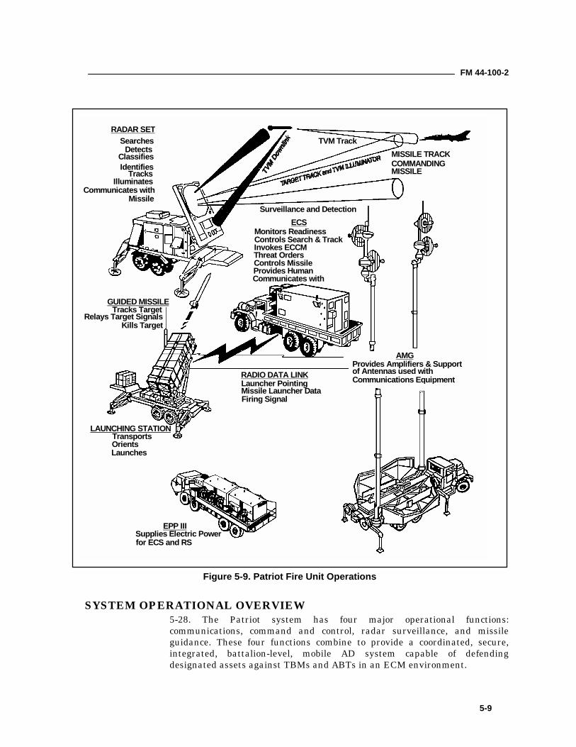
FM 44-100-2
5-9
SYSTEM OPERATIONAL OVERVIEW5-28. The Patriot system has four major operational functions:communications, command and control, radar surveillance, and missileguidance. These four functions combine to provide a coordinated, secure,integrated, battalion-level, mobile AD system capable of defendingdesignated assets against TBMs and ABTs in an ECM environment.
RADAR SETSearches
DetectsClassifiesIdentifies
TracksIlluminates
Communicates withMissile
MISSILE TRACKCOMMANDINGMISSILE
GUIDED MISSILETracks Target
Relays Target SignalsKills Target
LAUNCHING STATIONTransportsOrientsLaunches
RADIO DATA LINKLauncher PointingMissile Launcher DataFiring Signal
ECSMonitors ReadinessControls Search & TrackInvokes ECCMThreat OrdersControls MissileProvides HumanCommunicates with
AMGProvides Amplifiers & Supportof Antennas used withCommunications Equipment
EPP IIISupplies Electric Powerfor ECS and RS
Surveillance and Detection
TVM Track
Figure 5-9. Patriot Fire Unit Operations
FM 44-100-2
5-10
INFORMATION AND COORDINATION CENTRAL5-29. The ICC provides the automated data processing (ADP) andcommunications capabilities that are required to integrate with other ADsystems. The ICC communicates with the air defense brigade tacticaloperation center (TOC-AMDPCS) using either the Army tactical data link-1(ATDL-1) or tactical digital information link-B (TADIL-B) data link. In theabsence of a brigade TOC, the ICC can communicate directly with elementsof the USAF Tactical Air Control System/Tactical Air Defense System(TACS/TADS) using either TADIL-A, TADIL-B, or TADIL-J data links.5-30. The ICC can interface with other weapons surveillance and intelligencesystems using communications equipment mounted in the Tactical CommandSystem (TCS). The ICC receives intelligence and early warning informationfrom the CTT-H/R terminal and can establish an UHF TADIL-A data linkusing the TADIL-A suite of equipment in the TCS.
FIRE UNIT TARGET ENGAGEMENT SEQUENCE5-31. Surveillance and Detection. The RS searches the surveillance areaand detects, identifies, tracks, and illuminates targets. The ECS receivestarget track data from the RS and processes this information within theWCC. Targets are assessed and identified as unknown, friendly, or hostile.When a target has been identified as hostile, it may be engaged once theWCC sends a launch command to the selected LS. The LS receives its launchcommand from the WCC by way of fiber optic communications or by way of aVHF link, and a selected missile is launched. The RS acquires the launchedmissile and a two-way data link is established with the ECS WCC throughthe RS.5-32. Track via Missile. The Patriot missile is commanded to the vicinity ofthe target by the WCC and then the on-board missile seeker acquires thetarget. The target is then TVM, while the two-way data link is maintained atan increased rate. The missile moves to the intercept point while the RSilluminates the target.5-33. Target Intercept. At the proper time, the missile proximity fuse isarmed. This activates the warhead for target intercept and destruction(figure 5-9, page 5-9).
COMMUNICATIONS EQUIPMENT5-34. AN/ARC-187 UHF Radio. The AN/ARC-187 receive/transmit UHFradio is used for TADIL-A operations. It is used in the TCS and ICC.5-35. AN/GRC-103 UHF Radio. The AN/GRC-103, 12-channel, Band IIIradio set is used in every ICC, ECS, and CRG. Two corner reflector antennasare used for short-range communications, and the AMG is used for long-range communications. Encryption is provided by the KG-194A.5-36. AN/GSQ-240 JTIDS Class 2M Radio. The AN/GSQ-240 radio is ahigh-speed data radio that provides jam resistant ground-to-air and ground-to-ground data communications. It operates in a time-shared data networkproviding subscribers access to theater engagement operations surveillance
FM 44-100-2
5-11
and targeting information. JTIDS operates in the 960 MHz to 1215 MHzfrequency range.5-37. AN/TRC-170 Radio Terminal Set. The AN/TRC-170 radio providestactical multichannel digital troposcatter or line-of-sight systems fortransmission of analog and digital traffic. It operates in the 4 to 5 GHzranges with 8 to 144 channels and is housed in a HMMWV mounted shelter.It is used at the ICC for interface with the TCS.5-38. Commander’s Tactical Terminal/Hybrid Receive Unit. TheCommander’s Tactical Terminal/Hybrid Receive Unit (CTT/H-R) is aruggedized, dual channel terminal capable of receiving and processingbroadcasts from the Tactical Information Broadcast Service (TIBS)intelligence network and other communications networks. It operates withinthe 225 MHz to 1.4 GHz UHF range. It is used in the ICC and TCS.5-39. IHFR-AM. The AN/GRC-193A medium/high power radio set is used atbattalion, and brigade CPs primarily as backup communications for C2 whenat a static position. The AN/GRC-213 low power radio set is used at firingbatteries. Some units are using the AN/GRC-106A radio sets until replacedwith AN/GRC-193A or AN/GRC–213 radios.5-40. Mobile Subscriber Equipment. The mobile subscriber equipment(MSE) consists of an interface box at the ICC hardwired to a small extensionnode (SEN) van which will transmit the signal to other SENs, and variousdigital secure and non-secure voice telephones. The purpose is to allow thebattalion to communicate with higher echelons, other ADA units, and anyonein the net. MSE is not necessarily an organic asset; a supporting signalcompany may furnish it. It may be used to transmit TADIL-B and ADTL-1.5-41. VHF-FM. At the battalion level, FM radios are used for command,logistics, administrative, intelligence, and operations networks. SINCGARSare the primary radios for the FM networks.5-42. Wire. WD-1 and 26-pair cables are used to connect elements within thebattalion and battery for C2, administration, logistics, and CSS. The wirelines are connected with the UHF equipment to communicate withsubordinate, higher, and supporting units.
BATTALION COMMUNICATIONS REQUIREMENTS5-43. The communications system for Patriot battalions must providereliable, real-time or near real-time information to dispersed Patriotbatteries, higher headquarters, adjacent battalions, and supported units. Thecommunications system must be redundant to provide continuouscommunications even when the primary system fails. To effectively defeat theair threat, the Patriot battalion must maintain communications to supportthe following functions:
• Control of the air battle.• Command, administrative, and logistical lines with higher
headquarters, subordinate units, and lateral units.• Liaison with supported units or the units in whose area the Patriot
battalion is operating.
FM 44-100-2
5-12
5-44. Each Patriot battalion commander is responsible for establishing aneffective communications system. He exercises C2 of organic signal assetsthrough his signal officer. Communications are established from higher tolower, left to right, and supporting to supported (see FM 24-1 for moredetails). The battalion uses multichannel radio and wire nets to maintainexternal and internal communications. A communications platoon organic tothe Patriot battalion provides external and internal communications for thebattalion TOC (extended multichannel radio systems) and limited support tothe FU.5-45. The following digital links is used to transmit data:
• PADIL: An internal digital data link for communication betweenPatriot battalions and batteries. Patriot batteries are PADIL capableonly.
• ATDL-1: A secure, full-duplex, point-to-point digital data link thatinterconnects tactical air control systems and Army or Marinetactical air defense systems.
• TADIL-A: A secure, half-duplex, netted digital data link normallyoperated in a roll-call mode under control of a net control station toexchange information between land-based, airborne, and shipboardtactical data systems. NATO’s equivalent is Link 11.
• TADIL-B: A secure, full-duplex, point-to-point digital data link usedto connect Patriot brigades and SHORAD units to the CRC and otherpoints. NATO’s equivalent is Link 4.
• TADIL-J: A secure, high capacity, jam-resistant, nodeless data linkwhich uses the Joint Tactical Information Distribution System(JTIDS) transmission characteristics and the protocols, conventions,and fixed-length message formats defined by JTIDS. It is a time-shared net used by airborne, shipboard, and land-based tacticalcombat operations. NATO’s equivalent is Link 16.
EXTERNAL COMMUNICATIONS5-46. External communications are established with the ADA brigade andadjacent Patriot battalions. The battalion is also capable of communicatingwith a CRC, SHORAD battalion, THAAD battery, or a Hawk battalion.5-47. ADA Brigade. Communications with the ADA brigade supports airbattle C2. It also facilitates administrative, logistical, operational, andintelligence functions. Voice and data links are established via multichannelradio and MSE between brigade and battalion.5-48. The EAC ADA brigade uses MSE resources to establish and maintainan MSE network between the brigade and subordinate battalions. The corpsADA brigade establishes an MSE network using MSE assets from the corpssignal brigade. The primary means of communications with brigade is MSEfor all networks (data link, IRR, ADC, brigade command, and brigadeadmin/log). SINCGARS is the secondary means of communications with thebrigade for the ADC, brigade command, and brigade admin/log networks.5-49. Generally, three dedicated circuits are used for control of the air battle.One circuit is dedicated to automatic data link connectivity that uses either
FM 44-100-2
5-13
TADIL-B or ADTL-1. The brigade and battalion tactical directors (TD) usethe second circuit for the identification function. This is called IRR and isusually established on party line two. The brigade and battalion tacticaldirector assistants (TDA) use the third circuit for engagement functions. Thisis called ADC and is usually established on party line one. The brigadecommand and admin/log networks are accessed via MSE user terminals(DVNT/DSVT) on an as needed dial-up basis.5-50. IHFR-AM is used as a backup voice system for ADC and IRR.Battalions establish the AM net with brigade to pass messages and facilitatecommand, control, and coordination with higher echelons. Because ofeffective communications using MSE and SINCGARS, only a backup AMcapability between battalion and brigade is required.5-51. Adjacent Patriot Battalions. A Patriot battalion may establish aUHF multichannel communications system with an adjacent Patriotbattalion. Generally, each battalion for this external communications linkuses one terminal of a CRG. The EAC ADA brigade can also establish thelink. Because the Patriot UHF equipment provides a more effective link, useof a CRG is recommended for interbattalion communications. Battalions canexchange selected information using the Patriot air defense informationlanguage (PADIL) at a data exchange rate of 1,200 bits per second. Theinformation is exchanged to improve fire and track coordination.
5-52. Supported and Supporting Unit. Patriot battalions establishcommunications with the supported unit or the unit in whose area thebattalion is operating. Supporting units establish communications with thesupported unit. Normally, the direct support (DS) Patriot MaintenanceCompany collocates with or sends a liaison element to the Patriot battalionheadquarters. If this is not feasible, the DS Patriot Maintenance Companyenters the Patriot battalion VHF-FM administrative and logistics net. Allother units that provide support to the Patriot battalion on an area basisnormally do not establish communications with the Patriot battalion. TheADA brigade establishes communications with the COSCOM and TAACOMto provide support for Patriot units.
INTERNAL COMMUNICATIONS5-53. Internal communications are established with each Patriot FU tosupport the battalion command function. Internal communications alsofacilitate control of the air battle, administrative, intelligence, operations,and logistics functions, using UHF multichannel and VHF-FM nets.5-54. Multichannel Radio Systems. Patriot battalions use organicresources to establish a multichannel radio network to each subordinatebattery. When collocated, an FU can connect via specialty cable directly tobattalion. The C2 structure is heavily dependent upon communications forefficient operations. To pass real-time air battle and air traffic information,automatic data links must be established.5-55. To effectively fight the air battle, each FU needs three UHF circuits.One channel on each radio is used for the multirouting of data on theautomatic data link circuit. Normally, for standardization, channel four is
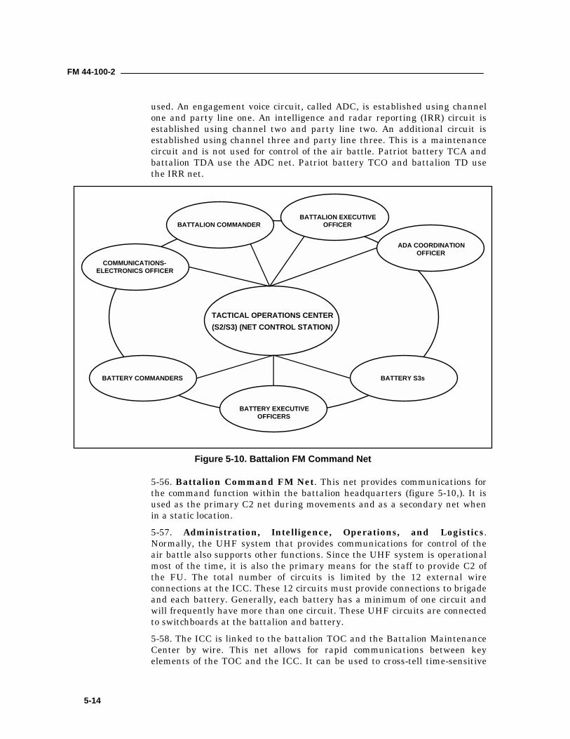
FM 44-100-2
5-14
used. An engagement voice circuit, called ADC, is established using channelone and party line one. An intelligence and radar reporting (IRR) circuit isestablished using channel two and party line two. An additional circuit isestablished using channel three and party line three. This is a maintenancecircuit and is not used for control of the air battle. Patriot battery TCA andbattalion TDA use the ADC net. Patriot battery TCO and battalion TD usethe IRR net.
5-56. Battalion Command FM Net. This net provides communications forthe command function within the battalion headquarters (figure 5-10,). It isused as the primary C2 net during movements and as a secondary net whenin a static location.5-57. Administration, Intelligence, Operations, and Logistics.Normally, the UHF system that provides communications for control of theair battle also supports other functions. Since the UHF system is operationalmost of the time, it is also the primary means for the staff to provide C2 ofthe FU. The total number of circuits is limited by the 12 external wireconnections at the ICC. These 12 circuits must provide connections to brigadeand each battery. Generally, each battery has a minimum of one circuit andwill frequently have more than one circuit. These UHF circuits are connectedto switchboards at the battalion and battery.5-58. The ICC is linked to the battalion TOC and the Battalion MaintenanceCenter by wire. This net allows for rapid communications between keyelements of the TOC and the ICC. It can be used to cross-tell time-sensitive
BATTALION COMMANDER
TACTICAL OPERATIONS CENTER(S2/S3) (NET CONTROL STATION)
BATTALION EXECUTIVEOFFICER
ADA COORDINATIONOFFICER
BATTERY S3s
BATTERY EXECUTIVEOFFICERS
BATTERY COMMANDERS
COMMUNICATIONS-ELECTRONICS OFFICER
Figure 5-10. Battalion FM Command Net
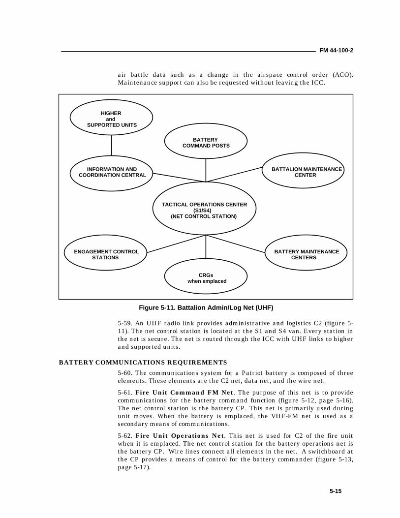
FM 44-100-2
5-15
air battle data such as a change in the airspace control order (ACO).Maintenance support can also be requested without leaving the ICC.
5-59. An UHF radio link provides administrative and logistics C2 (figure 5-11). The net control station is located at the S1 and S4 van. Every station inthe net is secure. The net is routed through the ICC with UHF links to higherand supported units.
BATTERY COMMUNICATIONS REQUIREMENTS5-60. The communications system for a Patriot battery is composed of threeelements. These elements are the C2 net, data net, and the wire net.5-61. Fire Unit Command FM Net. The purpose of this net is to providecommunications for the battery command function (figure 5-12, page 5-16).The net control station is the battery CP. This net is primarily used duringunit moves. When the battery is emplaced, the VHF-FM net is used as asecondary means of communications.5-62. Fire Unit Operations Net. This net is used for C2 of the fire unitwhen it is emplaced. The net control station for the battery operations net isthe battery CP. Wire lines connect all elements in the net. A switchboard atthe CP provides a means of control for the battery commander (figure 5-13,page 5-17).
BATTERYCOMMAND POSTS
TACTICAL OPERATIONS CENTER(S1/S4)
(NET CONTROL STATION)
BATTALION MAINTENANCECENTER
BATTERY MAINTENANCECENTERS
CRGswhen emplaced
ENGAGEMENT CONTROLSTATIONS
INFORMATION ANDCOORDINATION CENTRAL
HIGHERand
SUPPORTED UNITS
Figure 5-11. Battalion Admin/Log Net (UHF)
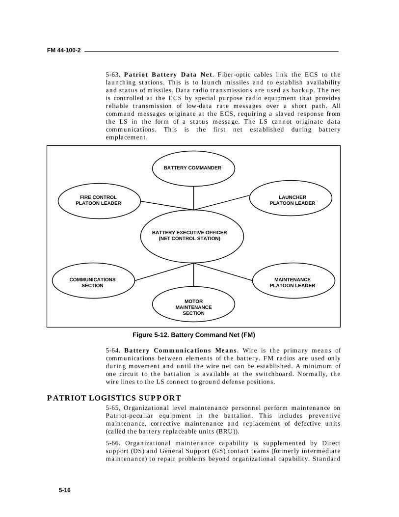
FM 44-100-2
5-16
5-63. Patriot Battery Data Net. Fiber-optic cables link the ECS to thelaunching stations. This is to launch missiles and to establish availabilityand status of missiles. Data radio transmissions are used as backup. The netis controlled at the ECS by special purpose radio equipment that providesreliable transmission of low-data rate messages over a short path. Allcommand messages originate at the ECS, requiring a slaved response fromthe LS in the form of a status message. The LS cannot originate datacommunications. This is the first net established during batteryemplacement.
5-64. Battery Communications Means. Wire is the primary means ofcommunications between elements of the battery. FM radios are used onlyduring movement and until the wire net can be established. A minimum ofone circuit to the battalion is available at the switchboard. Normally, thewire lines to the LS connect to ground defense positions.
PATRIOT LOGISTICS SUPPORT5-65, Organizational level maintenance personnel perform maintenance onPatriot-peculiar equipment in the battalion. This includes preventivemaintenance, corrective maintenance and replacement of defective units(called the battery replaceable units (BRU)).5-66. Organizational maintenance capability is supplemented by Directsupport (DS) and General Support (GS) contact teams (formerly intermediatemaintenance) to repair problems beyond organizational capability. Standard
BATTERY COMMANDER
BATTERY EXECUTIVE OFFICER(NET CONTROL STATION)
LAUNCHERPLATOON LEADER
MAINTENANCEPLATOON LEADER
MOTORMAINTENANCE
SECTION
COMMUNICATIONSSECTION
FIRE CONTROLPLATOON LEADER
Figure 5-12. Battery Command Net (FM)
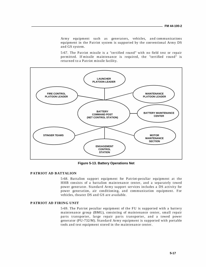
FM 44-100-2
5-17
Army equipment such as generators, vehicles, and communicationsequipment in the Patriot system is supported by the conventional Army DSand GS system.5-67. The Patriot missile is a "certified round" with no field test or repairpermitted. If missile maintenance is required, the "certified round" isreturned to a Patriot missile facility.
PATRIOT AD BATTALION5-68. Battalion support equipment for Patriot-peculiar equipment at theHHB consists of a battalion maintenance center, and a separately towedpower generator. Standard Army support services includes a DS activity forpower generation, air conditioning, and communication equipment. Forvehicles, theater DS and GS are available.
PATRIOT AD FIRING UNIT5-69. The Patriot peculiar equipment of the FU is supported with a batterymaintenance group (BMG), consisting of maintenance center, small repairparts transporter, large repair parts transporter, and a towed powergenerator (PU-732/M). Standard Army equipment is supported with portabletools and test equipment stored in the maintenance center.
LAUNCHERPLATOON LEADER
BATTERYCOMMAND POST
(NET CONTROL STATION)
MAINTENANCEPLATOON LEADER
MOTORMAINTENANCE
SECTION
ENGAGEMENTCONTROLSTATION
STINGER TEAMS
FIRE CONTROLPLATOON LEADER
BATTERY MAINTENANCECENTER
Figure 5-13. Battery Operations Net
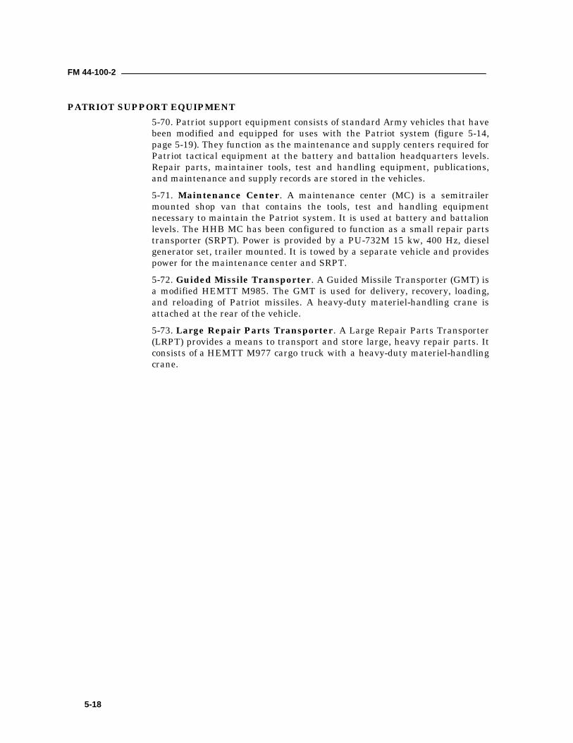
FM 44-100-2
5-18
PATRIOT SUPPORT EQUIPMENT5-70. Patriot support equipment consists of standard Army vehicles that havebeen modified and equipped for uses with the Patriot system (figure 5-14,page 5-19). They function as the maintenance and supply centers required forPatriot tactical equipment at the battery and battalion headquarters levels.Repair parts, maintainer tools, test and handling equipment, publications,and maintenance and supply records are stored in the vehicles.5-71. Maintenance Center. A maintenance center (MC) is a semitrailermounted shop van that contains the tools, test and handling equipmentnecessary to maintain the Patriot system. It is used at battery and battalionlevels. The HHB MC has been configured to function as a small repair partstransporter (SRPT). Power is provided by a PU-732M 15 kw, 400 Hz, dieselgenerator set, trailer mounted. It is towed by a separate vehicle and providespower for the maintenance center and SRPT.5-72. Guided Missile Transporter. A Guided Missile Transporter (GMT) isa modified HEMTT M985. The GMT is used for delivery, recovery, loading,and reloading of Patriot missiles. A heavy-duty materiel-handling crane isattached at the rear of the vehicle.5-73. Large Repair Parts Transporter. A Large Repair Parts Transporter(LRPT) provides a means to transport and store large, heavy repair parts. Itconsists of a HEMTT M977 cargo truck with a heavy-duty materiel-handlingcrane.
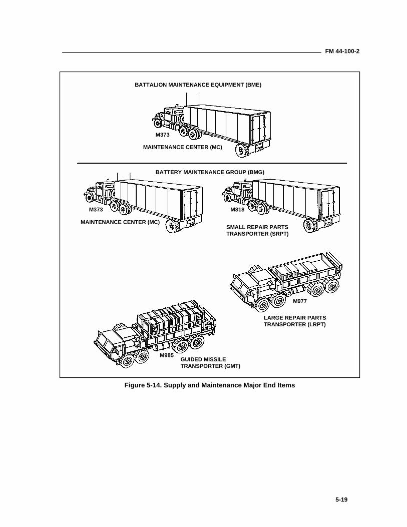
FM 44-100-2
5-19
BATTALION MAINTENANCE EQUIPMENT (BME)
MAINTENANCE CENTER (MC)
BATTERY MAINTENANCE GROUP (BMG)
M373
M373
MAINTENANCE CENTER (MC)SMALL REPAIR PARTSTRANSPORTER (SRPT)
M818
M977
M985
LARGE REPAIR PARTSTRANSPORTER (LRPT)
GUIDED MISSILETRANSPORTER (GMT)
Figure 5-14. Supply and Maintenance Major End Items
6-1
Chapter 6
Command and Control SystemsThis chapter discusses the command, control, communications, andintelligence collecting systems used by the Air Defense Artillery. Thesystems discussed are the Air and Missile Defense Planning and ControlSystem (AMDPCS), Tactical Command System (TCS), Patriot Master ICC(MICC), and FAAD Command, Control, Communications and Intelligence(C3I).
AIR AND MISSILE DEFENSE BATTLE COMMAND ORGANIZATIONS6-1. ADA commanders and leaders organize their personnel and equipment tocommand and control their units. There are three types of Command andControl (C2) organizations, which are standard in ADA units: command posts(CP), tactical operations centers (TOC), and fire direction centers (FDC).
COMMAND POST6-2. The principal facility employed by the commander to control operationsis a CP. The commander is located anywhere on the battlefield where he canbest command the force and is only present at the CP when necessary. A CPconsists of facilities for the commander, coordinating staff, and special staff.The organization of the CP reflects the commander's needs. CPs can beorganized by echelon, for example, a tactical CP, main CP, and rear CP. Thecommander may form an alternate or assault CP. ADA units from AAMDC toplatoon level form CPs tailored to their needs.6-3. A command post is organized to perform the following functions:
• Monitor the execution of operations.• Synchronize combat activities to sustain tempo and adjust the plan to
fit the situation.• Maintain the current operations situation.• Effectively manage logistics ensuring a continuity of combat
consumables.• Provide a focal point for the receipt and development of intelligence.• Plan future operations.• Monitor combat operations of supported, adjacent, and higher echelon
organizations.• Provide situational information to higher headquarters.
TACTICAL OPERATIONS CENTER6-4. A TOC is a sub-element of a headquarters CP with members of thecommander’s staff. A TOC consists of a physical grouping of the staff
FM 44-100-2
6-2
elements concerned with current and future tactical operations and tacticalsupport. A key standardized, digitized element of equipment in the AAMDCand brigade TOCs is the Air and Missile Defense Planning and ControlSystem. At the battalion TOC level, the key standard, digitized equipment isthe Air and Missile Defense workstation, which is completely compatible withthe AAMDC and brigade equipment.
FIRE DIRECTION CENTER6-5. A fire direction center is that element of a command post by means ofwhich the commander exercises fire direction and/or fire control (engagementoperations). The FDC receives target intelligence and fire control orders andtranslates them into appropriate fire directions and fire distribution.
AIR AND MISSILE DEFENSE PLANNING AND CONTROL SYSTEM6-6. The AMDPCS is a mission essential system that provides ADAcommanders, staffs and crews with automated capabilities to enhance theexecution of air and missile defense operations. The AMDPCS is composed ofa set of modular, reconfigurable, and standardized automated dataprocessing equipment, based on common hardware and software (CHS)developed for the Army Battle Command System (ABCS). The AMDPCScomponents will be designed for use with variants of the army standardintegrated command post system (SICPS) appropriate to the mission andmobility requirements of the supported unit. The reconfigurable nature of theAMDPCS provides an inherent “jump TOC” capability to support limitedAMDPCS operations. A portion of the AMDPCS is deployed into a theater ornew area of operations to provide a capability to perform critical command,control, communications and intelligence (C3I) functions until the entireAMDPCS is deployed. Appropriate configurations of the AMDPCS will befielded at all echelons of command and control.6-7. The AMDPCS integrates all air and missile defense sensors, weaponsand C3I capabilities into a cohesive, synergistic system capable of minimizingfratricide, protecting the force and defeating or neutralizing the air andmissile threat. It provides the automated interface for AMD elements attheater and below with the Army Battle Command System (ABCS) and theArmy Global Command and Control System (AGCCS), allowing unitcommanders and staffs to plan, coordinate and control the AMD fight. TheAMDPCS will also be capable of joint service information exchange andinterfacing with appropriate allied C3I systems.
OPERATIONAL CONCEPT6-8. The AMDPCS is the focal point for air and missile defense planning. Itprovides the means to horizontally and vertically integrate Army, joint andcombined forces to synchronize the actions of all AMD elements on thebattlefield.6-9. The AMDPCS provides a commander the timely information necessary toassess the situation, decide on a course of action (COA) and direct his forcesto act within the enemy’s decision cycle. The system is configurable byoperators to automatically collect, process, sort, categorize, classify, correlate,
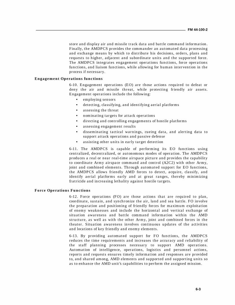
FM 44-100-2
6-3
store and display air and missile track data and battle command information.Finally, the AMDPCS provides the commander an automated data processingand exchange means by which to distribute his decisions, orders, plans andrequests to higher, adjacent and subordinate units and the supported force.The AMDPCS integrates engagement operations functions, force operationsfunctions, and liaison functions, while allowing for human intervention in theprocess if necessary.
Engagement Operations functions6-10. Engagement operations (EO) are those actions required to defeat ordeny the air and missile threat, while protecting friendly air assets.Engagement operations include the following:
• employing sensors• detecting, classifying, and identifying aerial platforms• assessing the threat• nominating targets for attack operations• directing and controlling engagements of hostile platforms• assessing engagement results• disseminating tactical warnings, cueing data, and alerting data to
support attack operations and passive defense• assisting other units in early target detection
6-11. The AMDPCS is capable of performing its EO functions usingcentralized, decentralized, or autonomous modes of operation. The AMDPCSproduces a real or near real-time airspace picture and provides the capabilityto coordinate Army airspace command and control (A2C2) with other Army,joint and combined elements. Through automated support for EO functions,the AMDPCS allows friendly AMD forces to detect, acquire, classify, andidentify aerial platforms early and at great ranges, thereby minimizingfratricide and increasing lethality against hostile targets.
Force Operations Functions6-12. Force operations (FO) are those actions that are required to plan,coordinate, sustain, and synchronize the air, land and sea battle. FO involvethe preparation and positioning of friendly forces for maximum exploitationof enemy weaknesses and include the horizontal and vertical exchange ofsituation awareness and battle command information within the AMDstructure, as well as with the other Army, joint and combined forces in thetheater. Situation awareness involves continuous updates of the activitiesand locations of key friendly and enemy elements.6-13. By providing automated support for FO functions, the AMDPCSreduces the time requirements and increases the accuracy and reliability ofthe staff planning processes necessary to support AMD operations.Automation of intelligence, operations, logistics and personnel actions,reports and requests ensures timely information and responses are providedto, and shared among, AMD elements and supported and supporting units soas to enhance the AMD unit’s capabilities to perform the assigned mission.
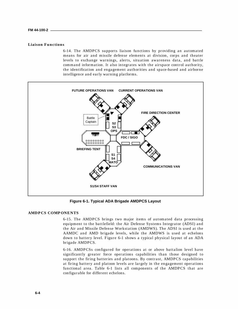
FM 44-100-2
6-4
Liaison Functions6-14. The AMDPCS supports liaison functions by providing an automatedmeans for air and missile defense elements at division, corps and theaterlevels to exchange warnings, alerts, situation awareness data, and battlecommand information. It also integrates with the airspace control authority,the identification and engagement authorities and space-based and airborneintelligence and early warning platforms.
AMDPCS COMPONENTS6-15. The AMDPCS brings two major items of automated data processingequipment to the battlefield: the Air Defense Systems Integrator (ADSI) andthe Air and Missile Defense Workstation (AMDWS). The ADSI is used at theAAMDC and AMD brigade levels, while the AMDWS is used at echelonsdown to battery level. Figure 6-1 shows a typical physical layout of an ADAbrigade AMDPCS.6-16. AMDPCSs configured for operations at or above battalion level havesignificantly greater force operations capabilities than those designed tosupport the firing batteries and platoons. By contrast, AMDPCS capabilitiesat firing battery and platoon levels are largely in the engagement operationsfunctional area. Table 6-1 lists all components of the AMDPCS that areconfigurable for different echelons.
CURRENT OPERATIONS VAN
COMMUNICATIONS VAN
S1/S4 STAFF VAN
S2 S3 OPS
BRIEFING TENT
FIRE DIRECTION CENTER
FDC / SIGO
FUTURE OPERATIONS VAN
S1S4
MATO
BattleCaptain
Figure 6-1. Typical ADA Brigade AMDPCS Layout
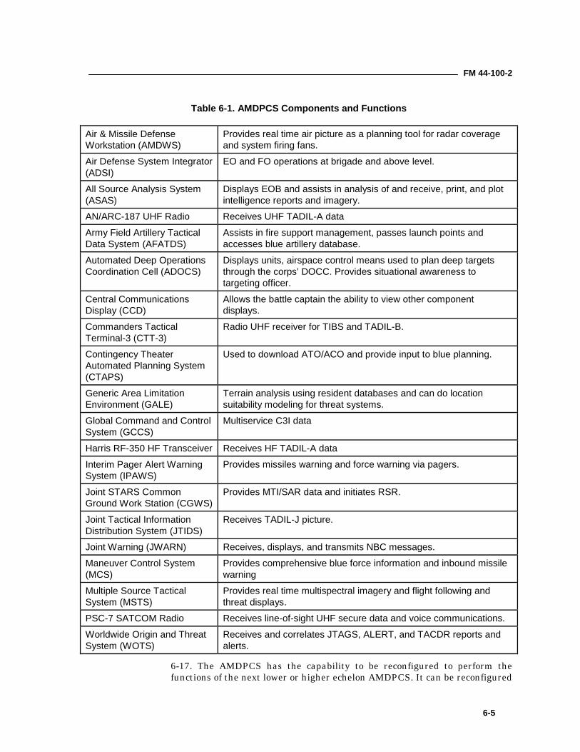
FM 44-100-2
6-5
Table 6-1. AMDPCS Components and Functions
Air & Missile DefenseWorkstation (AMDWS)
Provides real time air picture as a planning tool for radar coverageand system firing fans.
Air Defense System Integrator(ADSI)
EO and FO operations at brigade and above level.
All Source Analysis System(ASAS)
Displays EOB and assists in analysis of and receive, print, and plotintelligence reports and imagery.
AN/ARC-187 UHF Radio Receives UHF TADIL-A data
Army Field Artillery TacticalData System (AFATDS)
Assists in fire support management, passes launch points andaccesses blue artillery database.
Automated Deep OperationsCoordination Cell (ADOCS)
Displays units, airspace control means used to plan deep targetsthrough the corps’ DOCC. Provides situational awareness totargeting officer.
Central CommunicationsDisplay (CCD)
Allows the battle captain the ability to view other componentdisplays.
Commanders TacticalTerminal-3 (CTT-3)
Radio UHF receiver for TIBS and TADIL-B.
Contingency TheaterAutomated Planning System(CTAPS)
Used to download ATO/ACO and provide input to blue planning.
Generic Area LimitationEnvironment (GALE)
Terrain analysis using resident databases and can do locationsuitability modeling for threat systems.
Global Command and ControlSystem (GCCS)
Multiservice C3I data
Harris RF-350 HF Transceiver Receives HF TADIL-A data
Interim Pager Alert WarningSystem (IPAWS)
Provides missiles warning and force warning via pagers.
Joint STARS CommonGround Work Station (CGWS)
Provides MTI/SAR data and initiates RSR.
Joint Tactical InformationDistribution System (JTIDS)
Receives TADIL-J picture.
Joint Warning (JWARN) Receives, displays, and transmits NBC messages.
Maneuver Control System(MCS)
Provides comprehensive blue force information and inbound missilewarning
Multiple Source TacticalSystem (MSTS)
Provides real time multispectral imagery and flight following andthreat displays.
PSC-7 SATCOM Radio Receives line-of-sight UHF secure data and voice communications.
Worldwide Origin and ThreatSystem (WOTS)
Receives and correlates JTAGS, ALERT, and TACDR reports andalerts.
6-17. The AMDPCS has the capability to be reconfigured to perform thefunctions of the next lower or higher echelon AMDPCS. It can be reconfigured
FM 44-100-2
6-6
by the addition or deletion of modules, workstations, cells or software orthrough system initialization procedures IAW the assigned mission and taskorganization.
TACTICAL COMMAND SYSTEM6-18. The Patriot Tactical Command System (TCS) is a facility whichaccommodates the commander and staff of up to ten air defense personneland provides automated equipment to support force operations (FO) taskswhich complement the EO activities in the Patriot ICC. The TCS is mountedon an M934 5-ton expandable van. It is co-located with and interfaces directlyto the Patriot ICC using MSE and LAN, uses US Army common hardwareand software components, and is powered by a standard US Army 30 kw, 60Hz generator with UPS backup power.6-19. Automation is provided through the use of two Tactical PlannerWorkstations and a communications processor. The TCS workstationstandard software package is Air and Missile Defense Workstation (AMDWS)1.1. Automated functions internal to the TCS include the following areas:defense design (TBM and ABT planning), situation awareness, missionreporting, recording/replay of the air battle, and ICC initialization. Thefollowing summarizes the functions performed by the AMDWS:
• Maintain situation awareness of the hostile air threat.• Provide data required for air intelligence preparation of the
battlefield (IPB).• Maintain situation awareness during ongoing air defense operations.• Monitor logistical status reports.• Provide for the interface and data exchange between the TCS and
other elements of the ABCS.
MASTER INFORMATION AND COORDINATION CENTRAL6-20. The Patriot Information and Coordination Central has the capability tofunction as a master ICC (MICC) fire distribution element. Major features ofa MICC include:
• Increased external and internal interfaces• Brigade wide track management• Automatic fire distribution and battalion engagement assignment
6-21. A master ICC can work together with external elements. These may beas follows:
• subordinate or lateral battalions (SICC, MICC)• higher echelons (CRC, TAOC, AWACS)• up to 12 Fire Units (ECS)
FORWARD AREA AIR DEFENSE C3I SYSTEM6-22. The FAAD C3I system provides automated engagement operations (EO) andforce operations (FO) capabilities at the SHORAD battalion. EO capabilitiesinclude near-real-time early warning and target cueing information to SHORAD
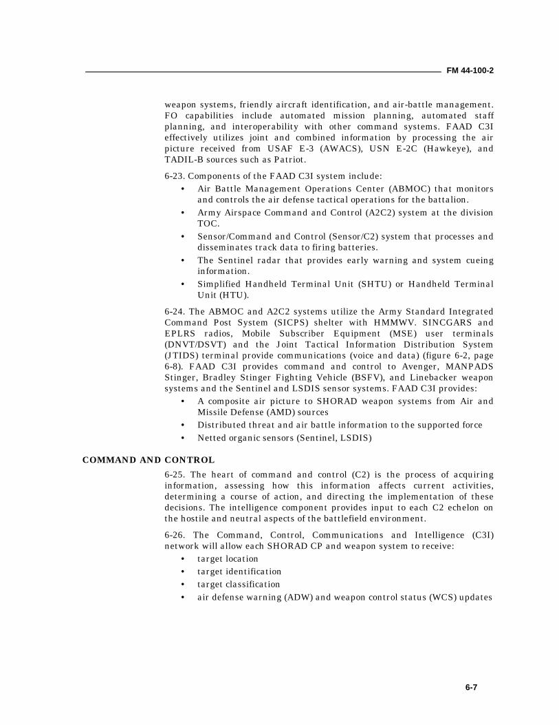
FM 44-100-2
6-7
weapon systems, friendly aircraft identification, and air-battle management.FO capabilities include automated mission planning, automated staffplanning, and interoperability with other command systems. FAAD C3Ieffectively utilizes joint and combined information by processing the airpicture received from USAF E-3 (AWACS), USN E-2C (Hawkeye), andTADIL-B sources such as Patriot.6-23. Components of the FAAD C3I system include:
• Air Battle Management Operations Center (ABMOC) that monitorsand controls the air defense tactical operations for the battalion.
• Army Airspace Command and Control (A2C2) system at the divisionTOC.
• Sensor/Command and Control (Sensor/C2) system that processes anddisseminates track data to firing batteries.
• The Sentinel radar that provides early warning and system cueinginformation.
• Simplified Handheld Terminal Unit (SHTU) or Handheld TerminalUnit (HTU).
6-24. The ABMOC and A2C2 systems utilize the Army Standard IntegratedCommand Post System (SICPS) shelter with HMMWV. SINCGARS andEPLRS radios, Mobile Subscriber Equipment (MSE) user terminals(DNVT/DSVT) and the Joint Tactical Information Distribution System(JTIDS) terminal provide communications (voice and data) (figure 6-2, page6-8). FAAD C3I provides command and control to Avenger, MANPADSStinger, Bradley Stinger Fighting Vehicle (BSFV), and Linebacker weaponsystems and the Sentinel and LSDIS sensor systems. FAAD C3I provides:
• A composite air picture to SHORAD weapon systems from Air andMissile Defense (AMD) sources
• Distributed threat and air battle information to the supported force• Netted organic sensors (Sentinel, LSDIS)
COMMAND AND CONTROL6-25. The heart of command and control (C2) is the process of acquiringinformation, assessing how this information affects current activities,determining a course of action, and directing the implementation of thesedecisions. The intelligence component provides input to each C2 echelon onthe hostile and neutral aspects of the battlefield environment.6-26. The Command, Control, Communications and Intelligence (C3I)network will allow each SHORAD CP and weapon system to receive:
• target location• target identification• target classification• air defense warning (ADW) and weapon control status (WCS) updates
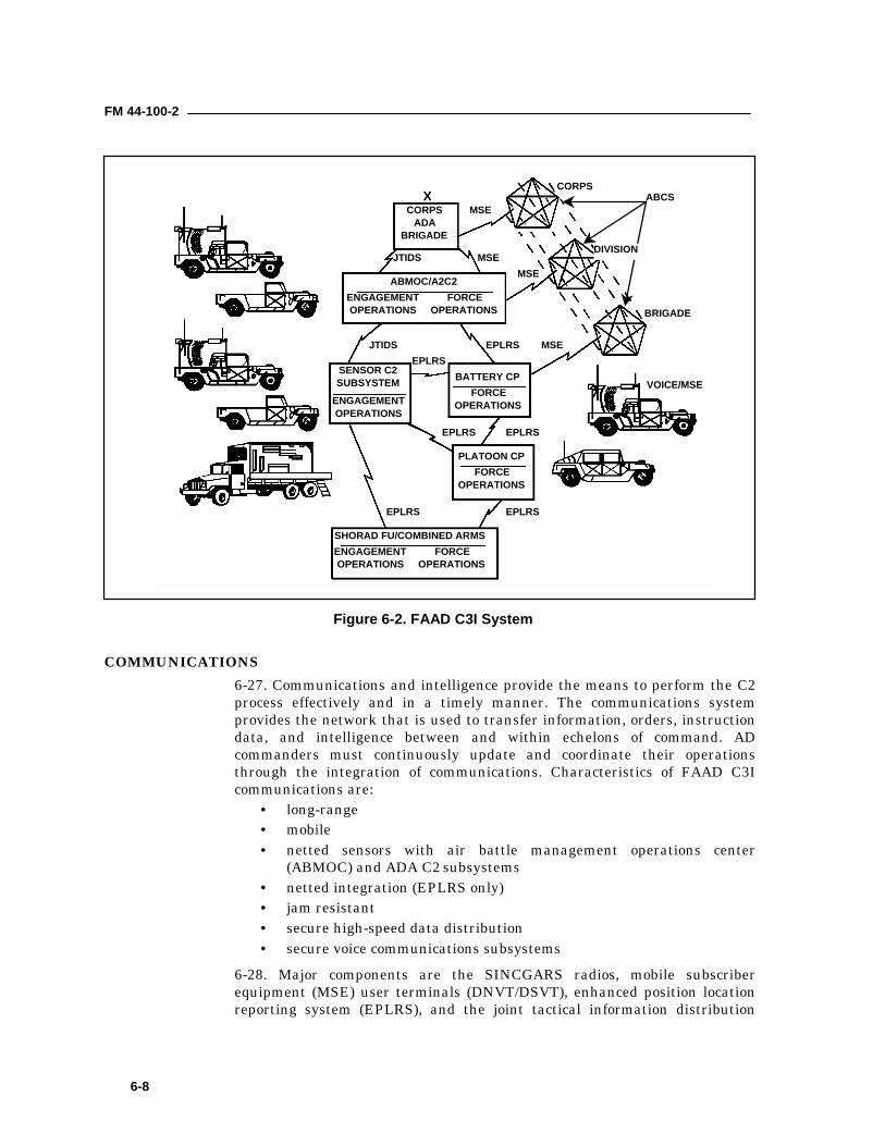
FM 44-100-2
6-8
COMMUNICATIONS6-27. Communications and intelligence provide the means to perform the C2process effectively and in a timely manner. The communications systemprovides the network that is used to transfer information, orders, instructiondata, and intelligence between and within echelons of command. ADcommanders must continuously update and coordinate their operationsthrough the integration of communications. Characteristics of FAAD C3Icommunications are:
• long-range• mobile• netted sensors with air battle management operations center
(ABMOC) and ADA C2 subsystems• netted integration (EPLRS only)• jam resistant• secure high-speed data distribution• secure voice communications subsystems
6-28. Major components are the SINCGARS radios, mobile subscriberequipment (MSE) user terminals (DNVT/DSVT), enhanced position locationreporting system (EPLRS), and the joint tactical information distribution
XCORPS
ADABRIGADE
ABMOC/A2C2ENGAGEMENTOPERATIONS
FORCEOPERATIONS
FORCEOPERATIONS
FORCEOPERATIONS
ENGAGEMENTOPERATIONS
SENSOR C2SUBSYSTEM BATTERY CP
PLATOON CP
SHORAD FU/COMBINED ARMSFORCE
OPERATIONSENGAGEMENTOPERATIONS
EPLRS EPLRS
EPLRSEPLRS
EPLRSEPLRSJTIDS
JTIDS MSE
MSE
MSE
MSE
VOICE/MSE
BRIGADE
CORPSABCS
DIVISION
Figure 6-2. FAAD C3I System
FM 44-100-2
6-9
system (JTIDS). These components are discussed in the followingparagraphs.
Single Channel Ground and Airborne Radio System6-29. SINCGARS radios are used for both secure voice and digital data in theFAAD C2I equipped SHORAD Battalions. SINCGARS operates in the 30 to88 MHz frequency range, in 25 kHz steps for a total of 2,320 channels. It canoperate in either a single channel or frequency-hopping mode.
Mobile Subscriber Equipment6-30. Mobile subscriber equipment (MSE) is a common-user, switchedcommunications system of linked switching nodes. The nodes form a grid thatprovides the force with an area common-user communications system. MSEis digital, secure, and flexible. It contains features that compensate for linkfailures, functional equipment outages, overload in traffic, and rapidmovement of users. FAAD C2I uses Mobile Subscriber Equipment (MSE) toshare TADIL-B track data with Patriot battalions and adjacent SHORADbattalions, as well as interface with other Army Battle Command Systemelements.
Enhanced Position Location Reporting System (EPLRS)6-31. Enhanced Position Location Reporting System (EPLRS) radios are usedfor secure digital data communications (figure 6-3). The EPLRS networksupports timely air track broadcast, two-way command and control,communication need-line allocation, and sensor netting. EPLRS resistsjamming by waveform design and signal processing techniques, relatively
BATTERY BOXUSER-TO-USER DATA
COMMUNICATIONS
SUPPORTSDUAL-LEVEL
SECURITY
ENHANCEDPLRS USERUNIT (EPUU)
USERREADOUT(URO)
PRIME POWER 28 VDC 14 WATTS
WEIGHT 24 LBS (10.9 KG)
(INCLUDES BATTERY BOX WITH 1 BATTERY)
EPUU DIMENSIONSHEIGHT 5.1 INCHES (12.95 CM)WIDTH 10.2 INCHES (25.91 CM)DEPTH 14.7 INCHES (37.34 CM)
Figure 6-3. Enhanced Position Location Reporting System (EPLRS)
FM 44-100-2
6-10
high values of effective radiated power, automatic network reconfigurationand path redundancy.
Joint Tactical Information Distribution System6-32. Joint Tactical Information Distribution System (JTIDS) is a jamresistant, secure data and voice communications system used for command,control, and identification. JTIDS provides FAAD C2I with a TADIL-J (link16) capability to participate on the JDN. JTIDS class 2M radios are located atthe divisional level in the Army Airspace Command and Control (A2C2) andat the battalion level in the ABMOC in support of FAAD C2I. The ABMOCand A2C2 use JTIDS to receive long range early warning, classification andidentification from the JDN (i.e. AWACS). That data is then correlated withother external sources (i.e. Patriot) and organic sensors, and is thenbroadcast to the sensor C2 nodes in the battalion. JTIDS provides theABMOC and A2C2 the means to transmit specific organic SHORAD airtracks (i.e. CM, UAV) to the JDN.
SENTINEL SYSTEM6-33. The Sentinel is organic to divisional SHORAD battalions, ACRs, and isreplacing LSDIS in light and special divisions (figure 6-4, page 6-13).Sentinel is designed to operate in all types of weather, severe ECMenvironments and survive anti-radiation missile (ARM) attacks. The missionof the Sentinel is to alert the Linebacker, the Bradley Stinger FightingVehicle, and MANPADS Stinger teams of hostile and unknown aircraft (FWand RW), cruise missiles, and unmanned aerial vehicles (UAV). It alsoprotects friendly forces from fratricide and provides air situational data tocommand and control centers.6-34. Sentinel track data is broadcast to SHORAD weapons and CommandPosts through the FAAD C2 system or, in the event a sensor node is notavailable, directly to the fire units over EPLRS or SINCGARS. The method oftransmission is operator-selectable from the remote control terminal (RCT)during initialization.6-35. The Sentinel system consists of an Antenna-Transceiver Group (ATG)mounted on a high-mobility trailer, and a HMMWV Group consisting of aM1097A1 HMMWV, a MEP-813A 10 kw 400 Hz generator, powerconditioning equipment and communications equipment. The system ismarch-ordered and emplaced by two soldiers and operated by a single soldier.It incorporates automatic fault detection and built in test equipment (BITE).The Sentinel is transportable by aircraft (to include helicopters), rail, or ship.
Sentinel Radar6-36. The Sentinel radar is a mobile, compact, modular, multifunction,phased-array radar. It consists of a radar antenna unit mounted on top of thetransceiver unit. The radar antenna unit also includes an IFF interrogator,an IFF antenna, and an auxiliary ECCM antenna mounted on a singlepedestal that rotates during operation. The antenna unit is lowered by handcrank to the stowed position for road march.
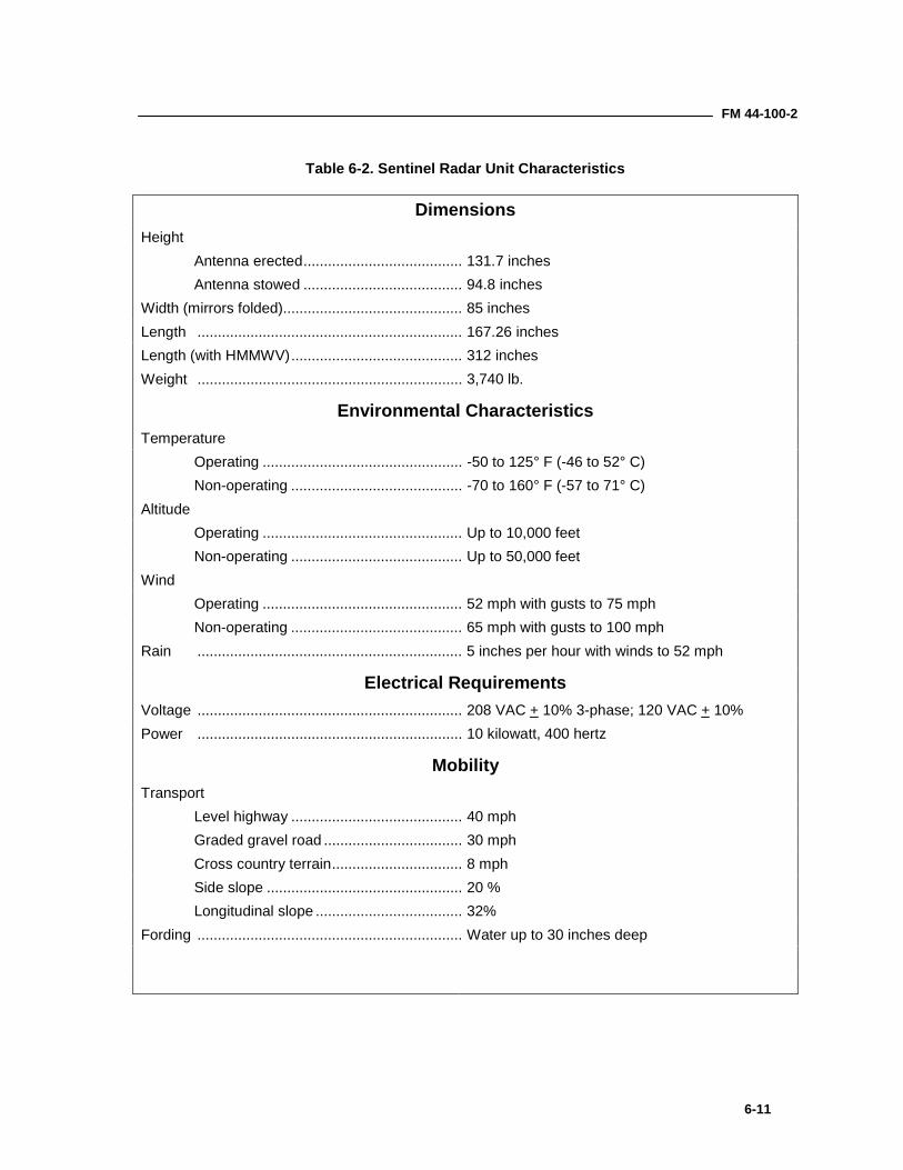
FM 44-100-2
6-11
Table 6-2. Sentinel Radar Unit Characteristics
DimensionsHeight
Antenna erected....................................... 131.7 inchesAntenna stowed ....................................... 94.8 inches
Width (mirrors folded)............................................ 85 inchesLength ................................................................. 167.26 inchesLength (with HMMWV).......................................... 312 inchesWeight ................................................................. 3,740 lb.
Environmental CharacteristicsTemperature
Operating ................................................. -50 to 125° F (-46 to 52° C)Non-operating .......................................... -70 to 160° F (-57 to 71° C)
AltitudeOperating ................................................. Up to 10,000 feetNon-operating .......................................... Up to 50,000 feet
WindOperating ................................................. 52 mph with gusts to 75 mphNon-operating .......................................... 65 mph with gusts to 100 mph
Rain ................................................................. 5 inches per hour with winds to 52 mph
Electrical RequirementsVoltage ................................................................. 208 VAC + 10% 3-phase; 120 VAC + 10%Power ................................................................. 10 kilowatt, 400 hertz
MobilityTransport
Level highway .......................................... 40 mphGraded gravel road .................................. 30 mphCross country terrain................................ 8 mphSide slope ................................................ 20 %Longitudinal slope .................................... 32%
Fording ................................................................. Water up to 30 inches deep
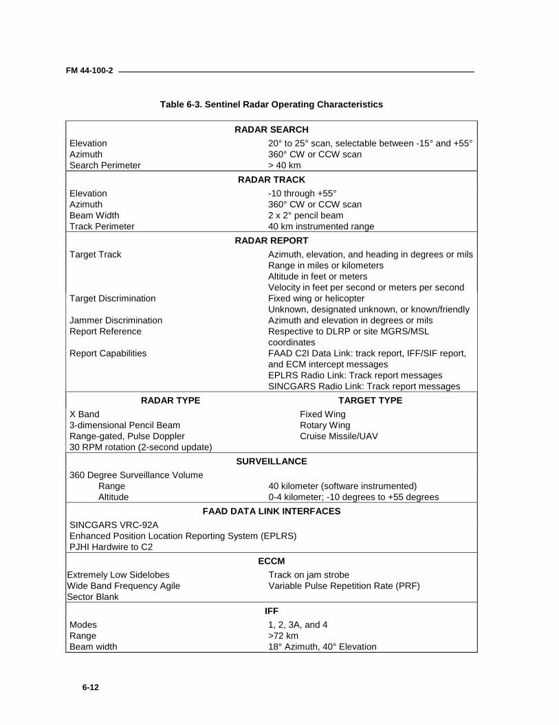
FM 44-100-2
6-12
Table 6-3. Sentinel Radar Operating Characteristics
RADAR SEARCH Elevation Azimuth Search Perimeter
20° to 25° scan, selectable between -15° and +55°360° CW or CCW scan> 40 km
RADAR TRACK Elevation Azimuth Beam Width Track Perimeter
-10 through +55°360° CW or CCW scan2 x 2° pencil beam40 km instrumented range
RADAR REPORT Target Track Azimuth, elevation, and heading in degrees or mils
Range in miles or kilometersAltitude in feet or metersVelocity in feet per second or meters per second
Target Discrimination Fixed wing or helicopterUnknown, designated unknown, or known/friendly
Jammer Discrimination Azimuth and elevation in degrees or mils Report Reference Respective to DLRP or site MGRS/MSL
coordinates Report Capabilities FAAD C2I Data Link: track report, IFF/SIF report,
and ECM intercept messagesEPLRS Radio Link: Track report messagesSINCGARS Radio Link: Track report messages
RADAR TYPE TARGET TYPE X Band 3-dimensional Pencil Beam Range-gated, Pulse Doppler 30 RPM rotation (2-second update)
Fixed WingRotary WingCruise Missile/UAV
SURVEILLANCE 360 Degree Surveillance Volume
RangeAltitude
40 kilometer (software instrumented)0-4 kilometer; -10 degrees to +55 degrees
FAAD DATA LINK INTERFACES SINCGARS VRC-92A Enhanced Position Location Reporting System (EPLRS) PJHI Hardwire to C2
ECCMExtremely Low SidelobesWide Band Frequency AgileSector Blank
Track on jam strobeVariable Pulse Repetition Rate (PRF)
IFF Modes Range Beam width
1, 2, 3A, and 4>72 km18° Azimuth, 40° Elevation
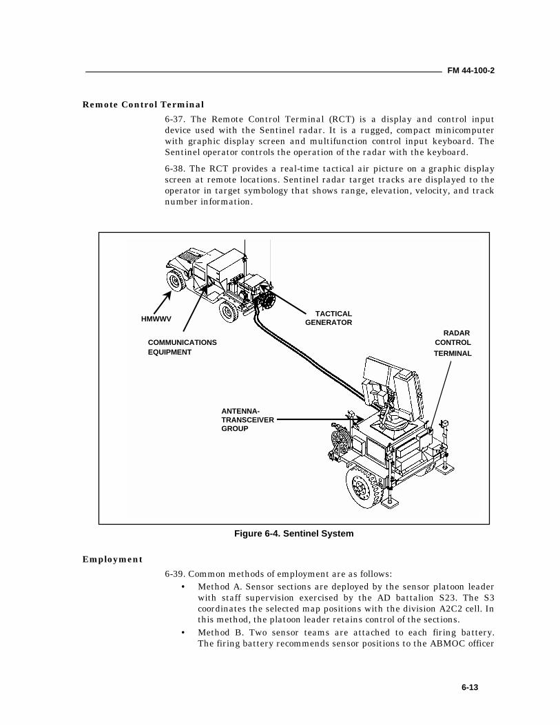
FM 44-100-2
6-13
Remote Control Terminal6-37. The Remote Control Terminal (RCT) is a display and control inputdevice used with the Sentinel radar. It is a rugged, compact minicomputerwith graphic display screen and multifunction control input keyboard. TheSentinel operator controls the operation of the radar with the keyboard.6-38. The RCT provides a real-time tactical air picture on a graphic displayscreen at remote locations. Sentinel radar target tracks are displayed to theoperator in target symbology that shows range, elevation, velocity, and tracknumber information.
Employment6-39. Common methods of employment are as follows:
• Method A. Sensor sections are deployed by the sensor platoon leaderwith staff supervision exercised by the AD battalion S23. The S3coordinates the selected map positions with the division A2C2 cell. Inthis method, the platoon leader retains control of the sections.
• Method B. Two sensor teams are attached to each firing battery.The firing battery recommends sensor positions to the ABMOC officer
HMWWV TACTICALGENERATOR
COMMUNICATIONSEQUIPMENT
ANTENNA-TRANSCEIVERGROUP
RADARCONTROLTERMINAL
Figure 6-4. Sentinel System
FM 44-100-2
6-14
in charge (OIC). The S3 coordinates these positions with the battalionS2 and division A2C2 cell. The S3 recommends approval or changes,and forwards the approved positions to the firing battery commander.
6-40. The AD battalion commander must consider certain deployment factorsto determine which method to use. These factors include but are not limitedto the following:
• mission• deployment of supported forces• deployment of fire units• the enemy threat, both air and ground• terrain• electronic warfare environment
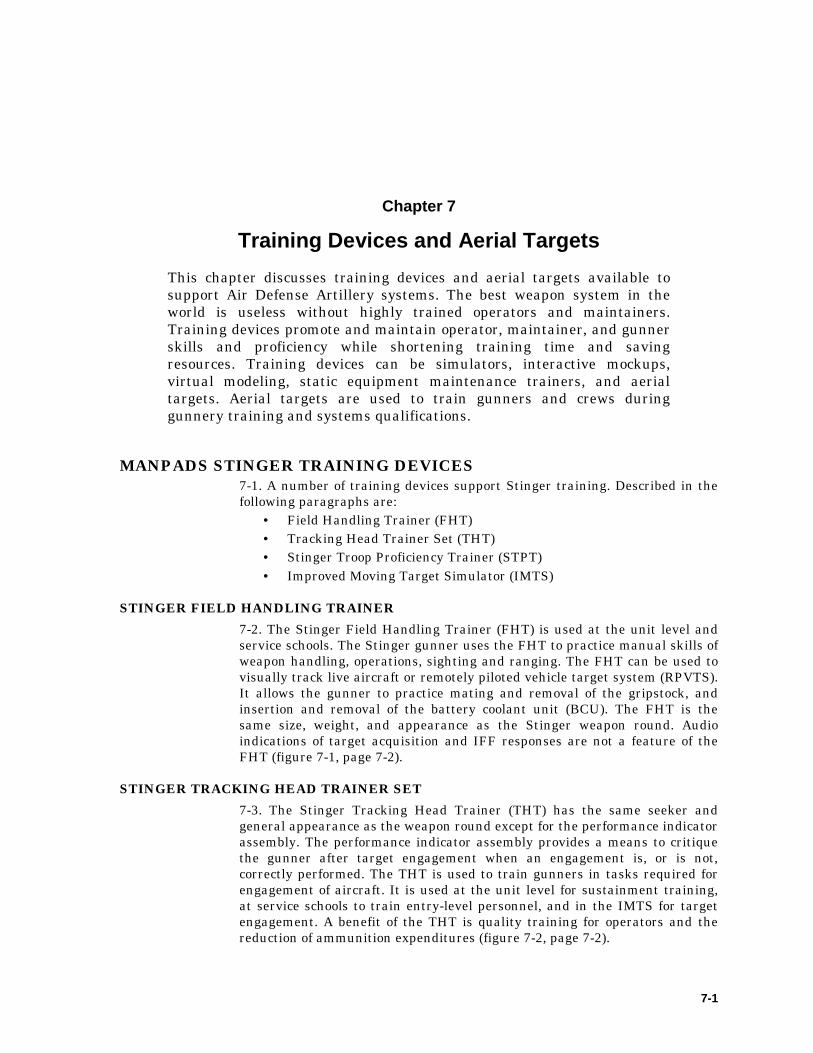
7-1
Chapter 7
Training Devices and Aerial TargetsThis chapter discusses training devices and aerial targets available tosupport Air Defense Artillery systems. The best weapon system in theworld is useless without highly trained operators and maintainers.Training devices promote and maintain operator, maintainer, and gunnerskills and proficiency while shortening training time and savingresources. Training devices can be simulators, interactive mockups,virtual modeling, static equipment maintenance trainers, and aerialtargets. Aerial targets are used to train gunners and crews duringgunnery training and systems qualifications.
MANPADS STINGER TRAINING DEVICES7-1. A number of training devices support Stinger training. Described in thefollowing paragraphs are:
• Field Handling Trainer (FHT)• Tracking Head Trainer Set (THT)• Stinger Troop Proficiency Trainer (STPT)• Improved Moving Target Simulator (IMTS)
STINGER FIELD HANDLING TRAINER7-2. The Stinger Field Handling Trainer (FHT) is used at the unit level andservice schools. The Stinger gunner uses the FHT to practice manual skills ofweapon handling, operations, sighting and ranging. The FHT can be used tovisually track live aircraft or remotely piloted vehicle target system (RPVTS).It allows the gunner to practice mating and removal of the gripstock, andinsertion and removal of the battery coolant unit (BCU). The FHT is thesame size, weight, and appearance as the Stinger weapon round. Audioindications of target acquisition and IFF responses are not a feature of theFHT (figure 7-1, page 7-2).
STINGER TRACKING HEAD TRAINER SET7-3. The Stinger Tracking Head Trainer (THT) has the same seeker andgeneral appearance as the weapon round except for the performance indicatorassembly. The performance indicator assembly provides a means to critiquethe gunner after target engagement when an engagement is, or is not,correctly performed. The THT is used to train gunners in tasks required forengagement of aircraft. It is used at the unit level for sustainment training,at service schools to train entry-level personnel, and in the IMTS for targetengagement. A benefit of the THT is quality training for operators and thereduction of ammunition expenditures (figure 7-2, page 7-2).
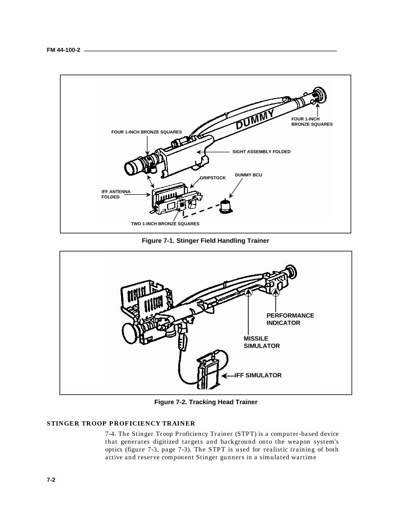
FM 44-100-2
7-2
STINGER TROOP PROFICIENCY TRAINER7-4. The Stinger Troop Proficiency Trainer (STPT) is a computer-based devicethat generates digitized targets and background onto the weapon system'soptics (figure 7-3, page 7-3). The STPT is used for realistic training of bothactive and reserve component Stinger gunners in a simulated wartime
DUMMY BCUGRIPSTOCK
TWO 1-INCH BRONZE SQUARES
FOUR 1-INCH BRONZE SQUARES
FOUR 1-INCHBRONZE SQUARES
SIGHT ASSEMBLY FOLDED
IFF ANTENNAFOLDED
Figure 7-1. Stinger Field Handling Trainer
PERFORMANCEINDICATOR
MISSILESIMULATOR
IFF SIMULATOR
Figure 7-2. Tracking Head Trainer
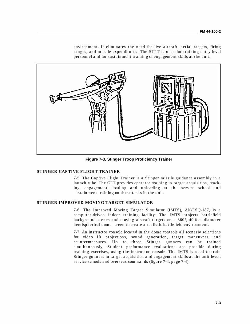
FM 44-100-2
7-3
environment. It eliminates the need for live aircraft, aerial targets, firingranges, and missile expenditures. The STPT is used for training entry-levelpersonnel and for sustainment training of engagement skills at the unit.
STINGER CAPTIVE FLIGHT TRAINER7-5. The Captive Flight Trainer is a Stinger missile guidance assembly in alaunch tube. The CFT provides operator training in target acquisition, track-ing, engagement, loading and unloading at the service school andsustainment training on these tasks in the unit.
STINGER IMPROVED MOVING TARGET SIMULATOR7-6. The Improved Moving Target Simulator (IMTS), AN/FSQ-187, is acomputer-driven indoor training facility. The IMTS projects battlefieldbackground scenes and moving aircraft targets on a 360°, 40-foot diameterhemispherical dome screen to create a realistic battlefield environment.7-7. An instructor console located in the dome controls all scenario selectionsfor video IR projections, sound generation, target maneuvers, andcountermeasures. Up to three Stinger gunners can be trainedsimultaneously. Student performance evaluations are possible duringtraining exercises, using the instructor console. The IMTS is used to trainStinger gunners in target acquisition and engagement skills at the unit level,service schools and overseas commands (figure 7-4, page 7-4).
Figure 7-3. Stinger Troop Proficiency Trainer
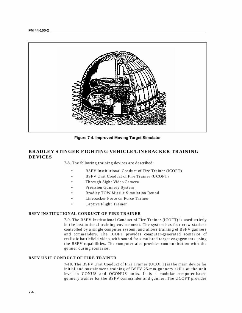
FM 44-100-2
7-4
BRADLEY STINGER FIGHTING VEHICLE/LINEBACKER TRAININGDEVICES
7-8. The following training devices are described:
• BSFV Institutional Conduct of Fire Trainer (ICOFT)• BSFV Unit Conduct of Fire Trainer (UCOFT)• Through Sight Video Camera• Precision Gunnery System• Bradley TOW Missile Simulation Round• Linebacker Force on Force Trainer• Captive Flight Trainer
BSFV INSTITUTIONAL CONDUCT OF FIRE TRAINER7-9. The BSFV Institutional Conduct of Fire Trainer (ICOFT) is used strictlyin the institutional training environment. The system has four crew stationscontrolled by a single computer system, and allows training of BSFV gunnersand commanders. The ICOFT provides computer-generated scenarios ofrealistic battlefield video, with sound for simulated target engagements usingthe BSFV capabilities. The computer also provides communication with thegunner during scenarios.
BSFV UNIT CONDUCT OF FIRE TRAINER7-10. The BSFV Unit Conduct of Fire Trainer (UCOFT) is the main device forinitial and sustainment training of BSFV 25-mm gunnery skills at the unitlevel in CONUS and OCONUS units. It is a modular computer-basedgunnery trainer for the BSFV commander and gunner. The UCOFT provides
Figure 7-4. Improved Moving Target Simulator
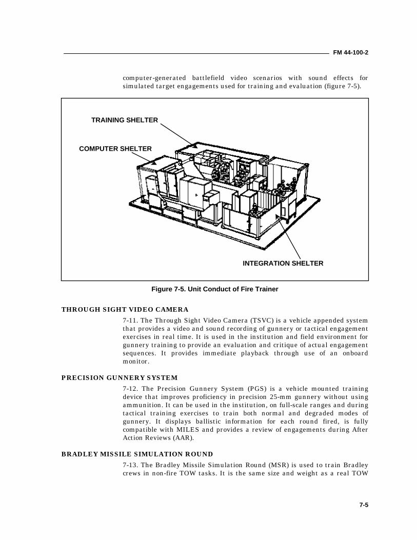
FM 44-100-2
7-5
computer-generated battlefield video scenarios with sound effects forsimulated target engagements used for training and evaluation (figure 7-5).
THROUGH SIGHT VIDEO CAMERA7-11. The Through Sight Video Camera (TSVC) is a vehicle appended systemthat provides a video and sound recording of gunnery or tactical engagementexercises in real time. It is used in the institution and field environment forgunnery training to provide an evaluation and critique of actual engagementsequences. It provides immediate playback through use of an onboardmonitor.
PRECISION GUNNERY SYSTEM7-12. The Precision Gunnery System (PGS) is a vehicle mounted trainingdevice that improves proficiency in precision 25-mm gunnery without usingammunition. It can be used in the institution, on full-scale ranges and duringtactical training exercises to train both normal and degraded modes ofgunnery. It displays ballistic information for each round fired, is fullycompatible with MILES and provides a review of engagements during AfterAction Reviews (AAR).
BRADLEY MISSILE SIMULATION ROUND7-13. The Bradley Missile Simulation Round (MSR) is used to train Bradleycrews in non-fire TOW tasks. It is the same size and weight as a real TOW
INTEGRATION SHELTER
TRAINING SHELTER
COMPUTER SHELTER
Figure 7-5. Unit Conduct of Fire Trainer
FM 44-100-2
7-6
missile. It is used to practice uploading, unloading, removing misfires andstoring TOW.
LINEBACKER FORCE ON FORCE TRAINER7-14. The Force on Force Trainer (FOFT) is a training device for theLinebacker. It will be used to replicate Stinger engagements in MILES FOFTexercises. It will provide simulation of missile firings, weapon effects,signature simulation and real time target assessment. The FOFT will be usedfor realistic training in combat training center exercises for gunners in asimulated wartime environment.
STINGER CAPTIVE FLIGHT TRAINER7-15. The Captive Flight Trainer is a simulated Stinger missile guidanceassembly in a launch tube. The CFT will be used to provide operator trainingin target acquisition tracking, engagement, loading and unloading at theservice school and sustain these tasks in the unit.
AVENGER TRAINING DEVICES7-16. The following Avenger training devices are described:
• Institutional Conduct of Fire Trainer• Captive Flight Trainer• Force on Force Trainer• Table Top Trainer• Troop Proficiency Trainer
AVENGER INSTITUTIONAL CONDUCT OF FIRE TRAINER7-17. The Avenger Institutional Conduct of Fire Trainer (ICOFT) is acomputer-based device that generates digitized battlefield scenarios on videodisplay terminals for the Avenger weapons system. The ICOFT provides fulltraining of all target engagement tasks. Each ICOFT consists of oneinstructor station and six student stations. The ICOFT is primarily used totrain IET enlisted students in their combat mission of target engagement,however, RC and OBC personnel are also trained using the ICOFT.
AVENGER CAPTIVE FLIGHT TRAINER7-18. The Captive Flight Trainer (CFT) is an actual Stinger missile withoutthe rocket motor and warhead. The guidance section provides realistic targetengagement training for Avenger teams in field units.
AVENGER FORCE-ON-FORCE TRAINER7-19. The Avenger Force-On-Force Trainer (FOFT) is an integrated laserengagement simulator used in the MILES FOFT exercises. It providessimulation of missile firings, weapons effects, signature simulation, and realtime target assessment. The FOFT is used for realistic training in combattraining center exercises for gunners in a simulated wartime environment.
FM 44-100-2
7-7
AVENGER TABLE TOP TRAINER7-20. The Avenger Table Top Trainer (TTT) is an interactive graphics trainerwith the principle features of the Avenger turret/gunner station. A 17-inchmonitor presents the out-of-window (canopy) view and the gunner’s FLIRdisplay. In addition, a FLIR field-of-view (FOV) footswitch and a tacticalgunner handstation provide the gunner-machine interface.
AVENGER TROOP PROFICIENCY TRAINER7-21. The Avenger Troop Proficiency Trainer (TPT) provides real time, free-play, and interactive simulation of stationary and remote operations. TheTPT is used in conjunction with tactical equipment at unit level to train andsustain crewmember engagement skills and to train entry level personnel atthe institution.
SENTINEL TRAINING DEVICES7-22. Sentinel training devices described are:
• Sentinel Troop Proficiency Trainer• Sentinel Institutional Maintenance Trainer• Sentinel Training System
SENTINEL TROOP PROFICIENCY TRAINER7-23. The Sentinel Troop Proficiency Trainer (TPT) is embedded into andused with the actual Sentinel equipment. The TPT will display incoming andoutgoing information that will stimulate operator procedural actions. Thiswill provide real time, free play interactive simulation that is representativeof initialization, BIT/BITE, operations and the evaluation of data/errormessages. The TPT will provide reports of operator actions and summaryreports used to determine operator performance to standard.
SENTINEL INSTITUTIONAL MAINTENANCE TRAINER7-24. The Sentinel Institutional Maintenance Trainer (SIMT) is a 3D trainerused for maintenance training. It is an institutional trainer consisting of aninstructor console and four student stations. The instructor console will beable to initialize, control and monitor any combination of training stations.The SIMT is capable of training at least 100 different maintenance tasks.
SENTINEL TRAINING SYSTEM7-25. The Sentinel Training System (STS) is capable of training students tooperate the Sentinel system. The STS simulates the functional, physicaloperations and characteristics of the system. The Instructor/Operator Station(IOS) has the capability to interface with and control up to eight studentstations to provide personnel training in the operator tasks associated withthe Sentinel system. The IOS has the capability to monitor any selectedstudent station.
FAAD C3I TRAINING DEVICES7-26. SHORAD is a complex system of new technologies and C3I is the gluethat binds these weapons systems together. C3I provides the ADA
FM 44-100-2
7-8
commander information about force operations as well as engagementoperations. The FAAD C3I training devices will serve to promote C3Ioperators’ efficiency in the tactical operations centers, A2C2, sensor C2, andbattery command post nodes. The training devices described are theInstitutional Conduct of Operations Trainer, and the C3I Troop ProficiencyTrainer
INSTITUTIONAL CONDUCT OF OPERATIONS TRAINER7-27. The FAADS C3I Institutional Conduct of Operations Trainer (ICOT) is ascheduled future computer-based training device. It will simulate all softwareoperations of the C3I nodes (A2C2 BTOC, battery CP, Sensor C2 nodes) suchas air tracks, symbology, range and bearing data, weapon control orders,status’s, ADW, fault simulation, BIT operations and continuous operations.Each ICOT will consist of six student stations and one instructor station. TheICOT will be used for realistic training for all C3I operators and ADA officers.This device will train initial entry and transition personnel at the institution.
C3 I TROOP PROFICIENCY TRAINER7-28. The C3I Troop Proficiency Trainer (TPT) is an embedded device withinthe system that supports a stand-alone capability to train operators toinitiate and monitor critical actions. The TPT allows the operator to sustainoperational skills in garrison or in the field without external training devices.
PATRIOT TRAINING DEVICES7-29. Patriot training devices serve to train initial entry personnel andsustain unit operator and maintainer efficiency in fighting the Air Defensebattle and maintaining the Patriot system's operational readiness. Thetraining devices described are:
• Patriot Organizational Maintenance Trainer• Patriot Conduct of Fire Trainer• Patriot Radar Set March Order and Emplacement Trainer• Patriot Communications System Task Trainer• Patriot Data Link Upgrade Task Trainer• Patriot Radar Frequency Comparator Task Trainer• Patriot Cooling Liquid Electron Tube Removal and Replacement Task
Trainer• Patriot Antenna Element Task Trainer• Patriot Embedded Trainers• Patriot Empty Round Trainer• Patriot Missile Round Trainer• Patriot Intermediate Maintenance Instructional Trainer
PATRIOT ORGANIZATIONAL MAINTENANCE TRAINER7-30. The Patriot Organizational Maintenance Trainer (POMT) provides arealistic static mockup of the Engagement Control Station (interior andexterior) with operator consoles interchangeable to the battalion Information
FM 44-100-2
7-9
Coordination Central (ICC) configuration, and the interior and exterior ofthe Radar Set shelter7-31. The POMT consists of the active maintenance trainer simulator and theparts task trainer. It is used to train maintenance personnel in the use ofDisplay Aided Maintenance (DAM), non-display aided maintenance (non-DAM), and BITE indicator procedures to diagnose, fault locate, remove andreplace defective components, and use software routines for the RS, the ECS,and ICC.
PATRIOT CONDUCT OF FIRE TRAINER7-32. The Patriot Conduct of Fire Trainer (PCOFT) is an institutionaltraining device for Patriot. It is a computer-driven battlefield system trainingdevice used at the USAADASCH and OCONUS. The PCOFT allows runningPatriot tactical TPT software using four enhanced weapons control computeroperator tactical trainers. The PCOFT has eight student consoles that arereproductions of the Patriot ECS and ICC tactical system operator consoles.One instructor station is used for controlling and monitoring the student con-soles. The PCOFT is used to train battalion Tactical Directors, TacticalDirector Assistants, and firing battery Tactical Control Officers and TacticalControl Assistants. Training is conducted on initialization procedures and ADbattles, individually or paired Fire Unit (FU), paired battalion or netted FU,and battalion. One PCOFT can simulate up to four battalions.
PATRIOT RADAR SET MARCH ORDER AND EMPLACEMENT TRAINER7-33. The Patriot Radar Set March Order and Emplacement Trainer (RSMO&E) trainer is an institutional training device. The MO&E trainer will bea mock-up of the Patriot RS physical characteristics as applied to MO&Etasks. The trainer consists of an RS trailer with electrical power, a rotatingplatform with antenna face, a shelter and outriggers.7-34. The MO&E trainer will be used to train Patriot missile crew members,operators and system mechanics, system maintenance technicians, and ADofficers in MO&E tasks. All MO&E tasks can be trained using this deviceinstead of the tactical systems.
PATRIOT COMMUNICATIONS SYSTEM TASK TRAINER7-35. The communication system task trainer consists of two tactical UHFradio stacks, a patch panel, an antenna control unit, three communicationssystems controls and a power distribution panel to provide hands-on trainingin initialization, operation, and maintenance of the AN/GRC-103 UHF radiocommunications systems.
PATRIOT DATA LINK UPGRADE TASK TRAINER7-36. The Patriot Data Link Upgrade (DLU) task trainer consists of a rack oftactical DLU equipment to provide hands-on training in operation of the DLUsystem. Although the same basic classroom configuration as the data linkterminal (DLT) used for the DLU modified DLT on the ECS, the assembliescomprising the trainer will be different. The DLU modification will add theSINCGARS radio AN/VRC-9O as the over-the-air communications link. Afiber optics unit will not be included due to its cost. Instead, the radio
FM 44-100-2
7-10
transmitters will need to be loaded (dummy load) the same as the unmodifiedDLT. A signal will be picked up, and the signal connected to the other DLUreceiver via hardwire. The DLU task trainer enables the student to performthe following emplacement tasks:
• Energize DLT module A2• De-energize DLT module A2• DLT power-up• Radio AN/VRC-9O loading• DLT self-test• DLT synchronizing• Security unit TSEC/KY-57 loading
PATRIOT RADAR FREQUENCY COMPARATOR TASK TRAINER7-37. The Patriot Radar Frequency (RF) Comparator task trainer is a mockupof the tactical radar RF Comparator and consists of tactical and mockupBattery Replaceable units (BRU). The following is a list of the removal andreplacement tasks that can be taught with the RF Comparator task trainer:
• Remove and replace radome with support and cooling (A139)• Pressure switch (S1). Remove and replace• Tube axial fan 81 or 82. Remove and replace• Radome Feed assembly. Remove and replace• Main Comparator horn assembly (A140) housing• Microwave device assemblies A142, A143, or A144• Microwave device assemblies A142, A143, or A144 air duct hose
assembly
PATRIOT COOLING LIQUID ELECTRON TUBE REMOVAL AND REPLACEMENTTASK TRAINER
7-38. The Patriot Cooling Liquid Electron Tube Removal and Replacement(CLET) (R&R) task trainer is a mockup of the right rear of the RS shelter, asimulated CLET rear door, and all associated hardware to perform R&Rprocedures. The CLET mockup includes four coolant hoses and two electricalcables.
PATRIOT ANTENNA ELEMENT TASK TRAINER7-39. The antenna element task trainer is a task training device used to trainthe removal and insertion of the individual elements in the Patriot phasedarray radar antenna. The radar antenna systems group diagnostics areperformed using either the ECS or the POMT. Identifying particular faultyelements will be accomplished using full-scale silk screen drawings, partialscale photographs, or overhead projections of line drawing or photographs.Using one of these media in lieu of tactical equipment better fills require-ments of student and instructor safety and convenience, and off-loads timefrom tactical equipment to training devices.
FM 44-100-2
7-11
PATRIOT EMBEDDED TRAINERS7-40. Patriot Embedded Trainers (ET) are troop proficiency trainers (TPT)with software programs that are built into the tactical system and providetraining in simulated AD battle scenarios. Tactical Directors (TD), TacticalControl Officers (TCO), Tactical Director Assistants (TDA), and TacticalControl Assistants (TCA) receive sustainment training and collective trainingin detection, acquisition, identification, and engagement in ECMenvironments.
PATRIOT EMPTY ROUND TRAINER7-41. The Patriot Empty Round Trainer (ERT) canister is a reworkedexpended Patriot missile round canister with appropriate markings. The ERTis used in both the institution and unit to train Patriot missile crewmembersin transporting, handling, and unloading procedures of expended roundcanisters.
PATRIOT MISSILE ROUND TRAINER7-42. The Patriot Missile Round Trainer (MRT) emulates a Patriot ready-round missile in size, weight, shape, and electrical connections. The MRT isused in both institution and unit to teach Patriot missile crewmembershandling, loading, and electrical checks without using a ready round.
PATRIOT INTERMEDIATE MAINTENANCE INSTRUCTIONAL TRAINER7-43. The Patriot Intermediate Maintenance Instructional Trainer (PIMIT) isa training device used to provide intermediate maintenance level training tostudents in the use of diagnostic programs, adjustments and calibrationprocedures, use of Test, Measuring and Diagnostic Equipment (TMDE), partslocation, and troubleshooting of system malfunctions.
THAAD TRAINING DEVICES7-44. THAAD training devices are used to support New Equipment Training(NET), institutional training, and unit training. THAAD system embeddedtraining (ET) capabilities will be used to the maximum extent possible. Thefollowing devices are described in detail in the THAAD OperationalRequirements Document (ORD):
• THAAD Institutional Conduct of Fire Trainer (ICOFT)• THAAD Missile Round Trainer (MRT)• THAAD Missile Round Pallet Trainer (MRPT)• THAAD Institutional Maintenance Trainer (IMT)• THAAD Explosive Ordnance Disposal Trainers (EODT)• THAAD March Order and Emplacement Trainer (MOET)• THAAD Embedded Training (ET) capability
INSTITUTIONAL CONDUCT OF FIRE TRAINER7-45. The purpose of the ICOFT is to train THAAD personnel in the operationof system integration, hardware and software. The ICOFT will consist ofthree nodes, BMC3I, Radar, and Launcher. The ICOFT Control Console will
FM 44-100-2
7-12
control the nodes. This training device will provide realistic institutionaltraining for BM/C4I, Radar, and Launcher operators/crewman, andcommanders and staff. The device will simulate system hardware interfacesand provides institutional training of operational functions. It will be used totrain operator/maintainers on the hardware and software of the threesystems segments independently, simultaneously, or collectively as anintegrated system. Each of the three nodes will run tactical software(embedded training, Interactive Electronic Technical Manuals (IETM), andhelp aids) and replicate tactical system operations. The ICOFT nodes can beconfigured in all THAAD system configurations so skills learned on theICOFT will be directly transferable to the actual system. The ICOFT alsoincludes Part Task Trainers (PTT) to teach initial switch settings andoperator/maintainer removal and replacement functions.
INSTITUTIONAL MAINTENANCE TRAINER7-46. The IMT will provide performance – oriented maintenance/repairtraining. This device is designed to train critical tasks associated withdiagnosis and fault isolation of the THAAD weapon system. This feature isrequired in order to assess the repairer’s performance. The IMT mustreplicate the tactical system in 3-D fidelity to train all critical tasks selectedby the proponent school for the device, identified to maintain the THAADsystem. This device provides realistic training without, the need for largequantities of costly tactical equipment. Skills learned on this devise must bedirectly transferable to the tactical equipment. The IMT consists of BM/C3I,radar and launcher PTT, 3-D mock-ups of the radar Cooling Equipment Unit(CEU), and instructor stations that are interchangeable between the PTT andCEU. The IMT emulates the THAAD system by responding in the samemanner and having the same performance fidelity as the objective system.
MISSILE ROUND TRAINERS7-47. The Missile Round Trainer consist of two separate configurations, theMissile Round Pallet Trainer (MRPT) and the Missile Round Trainer (MRT).The purpose of the Missile Round Pallet Trainer (MRPT) and the MissileRound Trainer (MRT) is to train operators in the handling of the THAADmissile at the institution and unit. Both configurations are used inconjunction with the THAAD launcher for training. The MRPT and MRT willsimulate the weight, balance and physical characteristics of the THAADmissile and will be used to train load/reload, hangfire and misfire procedures,and to practice missile handling and transporting procedures.
EXPLOSIVE ORDNANCE DISPOSAL TRAINERS7-48. The purpose of this device is to train Explosive Ordnance Disposal(EOD) personnel to recognize inherent hazards associated with thecomponents of the missile and practice EOD handling procedures. There aretwo (2) separate EOD trainers. They are the Practical Explosive OrdnanceDisposal System Trainer (PEST) and the Classroom Explosive OrdnanceDisposal System Trainer (CEST). The PEST is a full-scale inert model of theproduction THAAD missile and canister. The CEST is a half-scale inertmodel of the production THAAD missile and canister that has a cutaway ofthe areas containing explosive, hazardous and classified components.
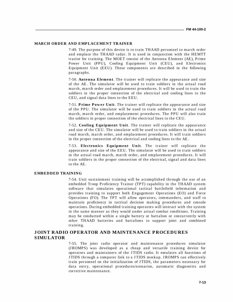
FM 44-100-2
7-13
MARCH ORDER AND EMPLACEMENT TRAINER7-49. The purpose of this device is to train THAAD personnel to march orderand emplace the THAAD radar. It is used in conjunction with the HEMTTtractor for training. The MOET consist of the Antenna Element (AE), PrimePower Unit (PPU), Cooling Equipment Unit (CEU), and ElectronicsEquipment Unit (EEU). These components are described in the followingparagraphs.7-50. Antenna Element. The trainer will replicate the appearance and sizeof the AE. The simulator will be used to train soldiers in the actual roadmarch, march order and emplacement procedures. It will be used to train thesoldiers in the proper connection of the electrical and cooling lines to theCEU, and signal data lines to the EEU.7-51. Prime Power Unit. The trainer will replicate the appearance and sizeof the PPU. The simulator will be used to train soldiers in the actual roadmarch, march order, and emplacement procedures. The PPU will also trainthe soldiers in proper connection of the electrical lines to the CEU.7-52. Cooling Equipment Unit. The trainer will replicate the appearanceand size of the CEU. The simulator will be used to train soldiers in the actualroad march, march order, and emplacement procedures. It will train soldiersin the proper connection of the electrical and cooling lines to the AE.7-53. Electronics Equipment Unit. The trainer will replicate theappearance and size of the EEU. The simulator will be used to train soldiersin the actual road march, march order, and emplacement procedures. It willtrain soldiers in the proper connection of the electrical, signal and data linesto the AE.
EMBEDDED TRAINING7-54. Unit sustainment training will be accomplished through the use of anembedded Troop Proficiency Trainer (TPT) capability in the THAAD systemsoftware that simulates operational tactical battlefield information andprovides training to support both Engagement Operations (EO) and ForceOperations (FO). The TPT will allow operators, commanders, and staff tomaintain proficiency in tactical decision making procedures and consoleoperations. During embedded training operators will interact with the systemin the same manner as they would under actual combat conditions. Trainingmay be conducted within a single battery or battalion or concurrently withother THAAD batteries and battalions to support joint and combinedtraining.
JOINT RADIO OPERATOR AND MAINTENANCE PROCEDURESSIMULATOR
7-55. The joint radio operator and maintenance procedures simulator(JROMPS) was developed as a cheap and versatile training device foroperators and maintainers of the JTIDS radio. It emulates all functions ofJTIDS through a computer link to a JTIDS mockup. JROMPS can effectivelytrain personnel on the initialization of JTIDS, the parameters necessary fordata entry, operational procedures/scenarios, automatic diagnostics andcorrective maintenance.
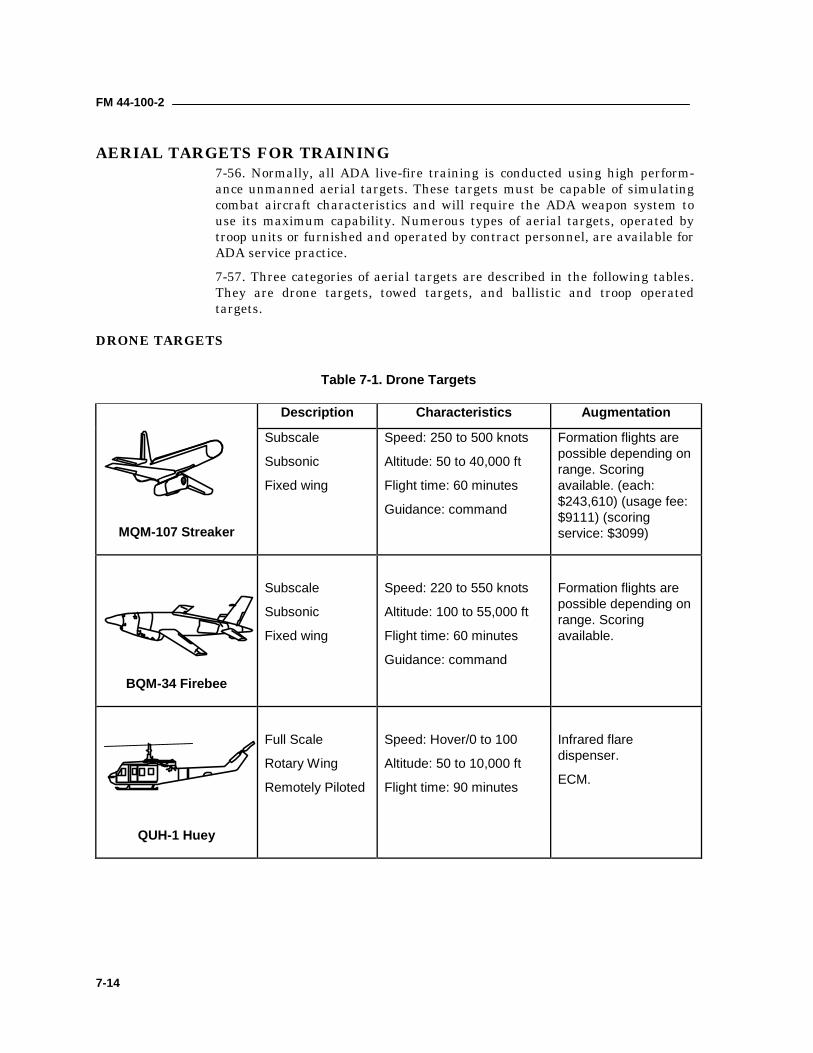
FM 44-100-2
7-14
AERIAL TARGETS FOR TRAINING7-56. Normally, all ADA live-fire training is conducted using high perform-ance unmanned aerial targets. These targets must be capable of simulatingcombat aircraft characteristics and will require the ADA weapon system touse its maximum capability. Numerous types of aerial targets, operated bytroop units or furnished and operated by contract personnel, are available forADA service practice.7-57. Three categories of aerial targets are described in the following tables.They are drone targets, towed targets, and ballistic and troop operatedtargets.
DRONE TARGETS
Table 7-1. Drone Targets
Description Characteristics Augmentation
MQM-107 Streaker
Subscale
Subsonic
Fixed wing
Speed: 250 to 500 knots
Altitude: 50 to 40,000 ft
Flight time: 60 minutes
Guidance: command
Formation flights arepossible depending onrange. Scoringavailable. (each:$243,610) (usage fee:$9111) (scoringservice: $3099)
BQM-34 Firebee
Subscale
Subsonic
Fixed wing
Speed: 220 to 550 knots
Altitude: 100 to 55,000 ft
Flight time: 60 minutes
Guidance: command
Formation flights arepossible depending onrange. Scoringavailable.
QUH-1 Huey
Full Scale
Rotary Wing
Remotely Piloted
Speed: Hover/0 to 100
Altitude: 50 to 10,000 ft
Flight time: 90 minutes
Infrared flaredispenser.
ECM.
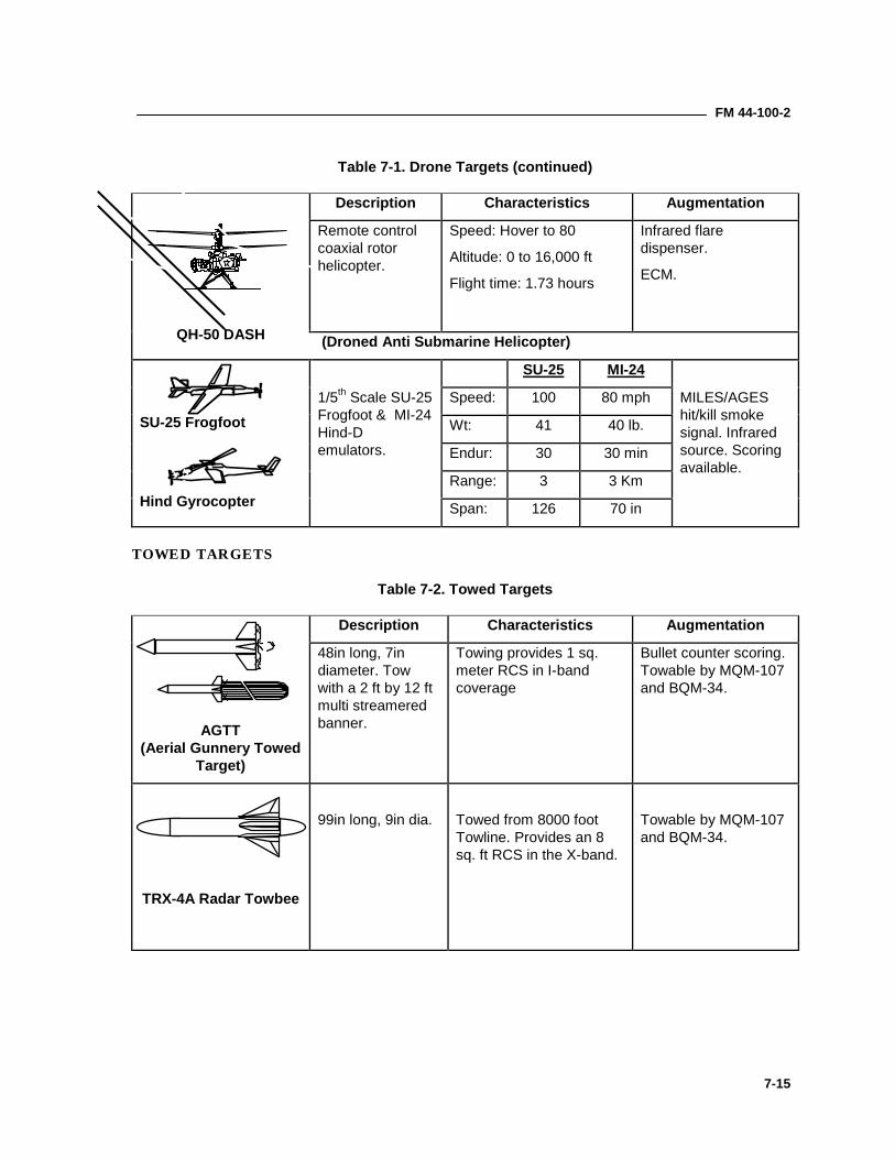
FM 44-100-2
7-15
Table 7-1. Drone Targets (continued)
Description Characteristics Augmentation
Remote controlcoaxial rotorhelicopter.
Speed: Hover to 80
Altitude: 0 to 16,000 ft
Flight time: 1.73 hours
Infrared flaredispenser.
ECM.
QH-50 DASH (Droned Anti Submarine Helicopter)
SU-25 MI-24
Speed: 100 80 mph
Wt: 41 40 lb.
Endur: 30 30 min
Range: 3 3 Km
SU-25 Frogfoot
Hind Gyrocopter
1/5th Scale SU-25Frogfoot & MI-24Hind-Demulators.
Span: 126 70 in
MILES/AGEShit/kill smokesignal. Infraredsource. Scoringavailable.
TOWED TARGETS
Table 7-2. Towed Targets
Description Characteristics Augmentation
AGTT(Aerial Gunnery Towed
Target)
48in long, 7indiameter. Towwith a 2 ft by 12 ftmulti streameredbanner.
Towing provides 1 sq.meter RCS in I-bandcoverage
Bullet counter scoring.Towable by MQM-107and BQM-34.
TRX-4A Radar Towbee
99in long, 9in dia. Towed from 8000 footTowline. Provides an 8sq. ft RCS in the X-band.
Towable by MQM-107and BQM-34.
XX
XXX
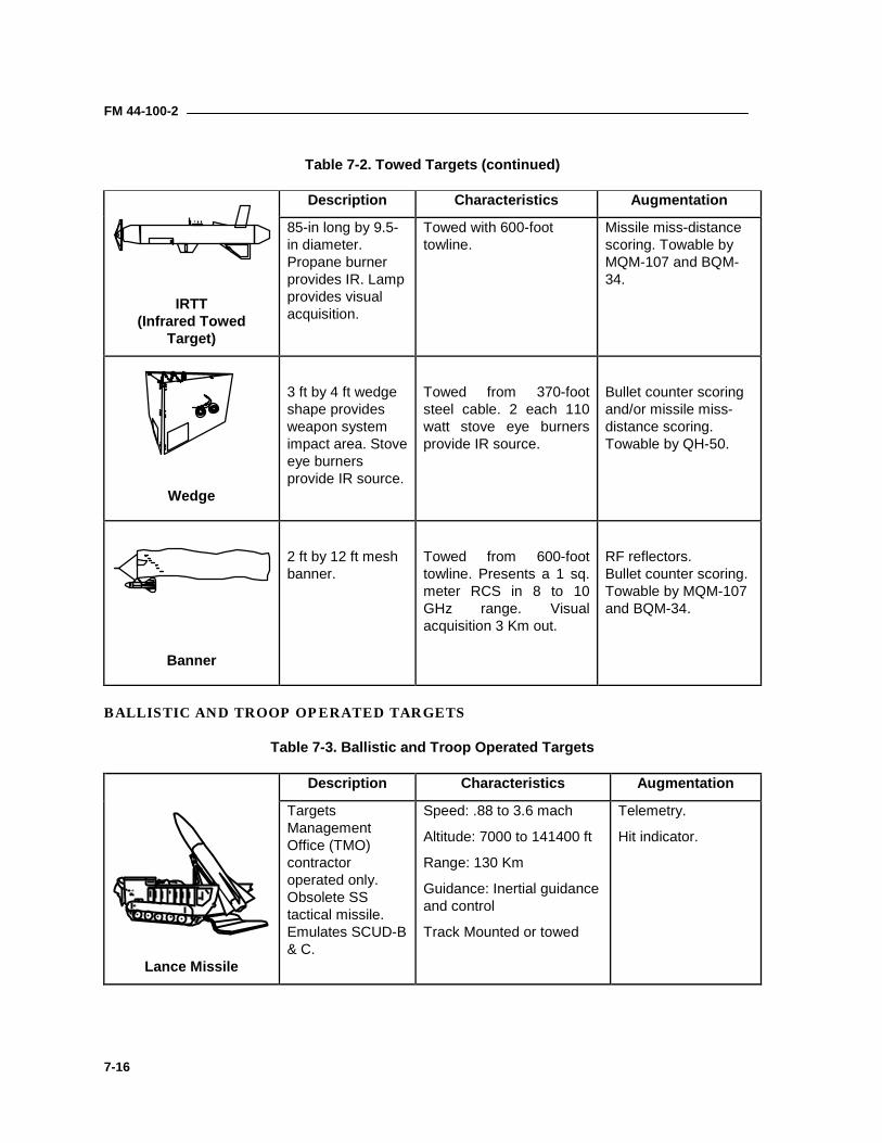
FM 44-100-2
7-16
Table 7-2. Towed Targets (continued)
Description Characteristics Augmentation
IRTT(Infrared Towed
Target)
85-in long by 9.5-in diameter.Propane burnerprovides IR. Lampprovides visualacquisition.
Towed with 600-foottowline.
Missile miss-distancescoring. Towable byMQM-107 and BQM-34.
Wedge
3 ft by 4 ft wedgeshape providesweapon systemimpact area. Stoveeye burnersprovide IR source.
Towed from 370-footsteel cable. 2 each 110watt stove eye burnersprovide IR source.
Bullet counter scoringand/or missile miss-distance scoring.Towable by QH-50.
Banner
2 ft by 12 ft meshbanner.
Towed from 600-foottowline. Presents a 1 sq.meter RCS in 8 to 10GHz range. Visualacquisition 3 Km out.
RF reflectors.Bullet counter scoring.Towable by MQM-107and BQM-34.
BALLISTIC AND TROOP OPERATED TARGETS
Table 7-3. Ballistic and Troop Operated Targets
Description Characteristics Augmentation
Lance Missile
TargetsManagementOffice (TMO)contractoroperated only.Obsolete SStactical missile.Emulates SCUD-B& C.
Speed: .88 to 3.6 mach
Altitude: 7000 to 141400 ft
Range: 130 Km
Guidance: Inertial guidanceand control
Track Mounted or towed
Telemetry.
Hit indicator.
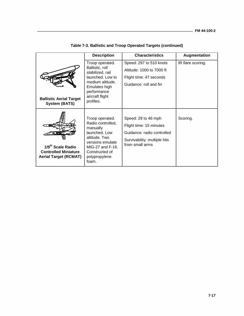
FM 44-100-2
7-17
Table 7-3. Ballistic and Troop Operated Targets (continued)
Description Characteristics Augmentation
Ballistic Aerial TargetSystem (BATS)
Troop operated.Ballistic, rollstabilized, raillaunched. Low tomedium altitude.Emulates highperformanceaircraft flightprofiles.
Speed: 297 to 510 knots
Altitude: 1000 to 7000 ft
Flight time: 47 seconds
Guidance: roll and fin
IR flare scoring.
1/9th Scale RadioControlled Miniature
Aerial Target (RCMAT)
Troop operated.Radio controlled,manuallylaunched. Lowaltitude. Twoversions emulateMIG-27 and F-16.Constructed ofpolypropylenefoam.
Speed: 29 to 46 mph
Flight time: 15 minutes
Guidance: radio controlled
Survivability: multiple hitsfrom small arms
Scoring.
A-1
Appendix A
ADA Employment Principles, Guidelines,and Priorities
This appendix describes how ADA commanders use employmentprinciples and guidelines and priority considerations to design air andmissile defenses. ADA commanders at all echelons use these principles,guidelines, and considerations for AMD planning. When applying theseprinciples and guidelines, planners must consider the tactical andtechnical capabilities of each weapon and sensor system as well as therelevant factors of METT-TC, IPB, and the air and missile defensepriorities.
EMPLOYMENT PRINCIPLESA-1. Commanders apply four principles when planning active air and missiledefense operations. These principles are mass, mix, mobility, and integration.
MASSA-2. Mass is the concentration of air and missile defense combat power. It isachieved by assigning enough firepower to successfully defend the force or theasset against air and missile attack or surveillance. To mass air and missiledefense combat power, commanders may have to accept risks in other areasof the battlefield.
MIXA-3. Mix is the employment of a combination of weapons systems to protectthe force from the air threat. Mix offsets the limitations of one system withthe capabilities of another and complicates the problem of the attacker. Alljoint and combined arms resources are considered when applying thisprinciple. Proper mix causes enemy aircraft to adjust their tactics. Enemymaneuvers designed to defeat one weapon system may make an aircraftvulnerable to another weapon system.
MOBILITYA-4. Mobility is the capability to move from place to place while retaining theability to perform the air and missile defense mission. The mobility of air andmissile defense resources must be equivalent to the mobility of the supportedasset. First priority for mobility should be planning moves that supportaccomplishment of the mission. Tactical situations may dictate additionalmoves to enhance survivability.
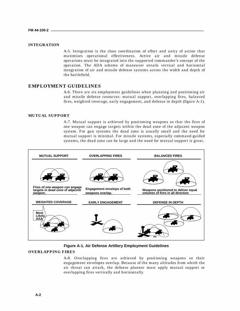
FM 44-100-2
A-2
INTEGRATIONA-5. Integration is the close coordination of effort and unity of action thatmaximizes operational effectiveness. Active air and missile defenseoperations must be integrated into the supported commander's concept of theoperation. The ADA scheme of maneuver entails vertical and horizontalintegration of air and missile defense systems across the width and depth ofthe battlefield.
EMPLOYMENT GUIDELINESA-6. There are six employment guidelines when planning and positioning airand missile defense resources: mutual support, overlapping fires, balancedfires, weighted coverage, early engagement, and defense in depth (figure A-1).
MUTUAL SUPPORTA-7. Mutual support is achieved by positioning weapons so that the fires ofone weapon can engage targets within the dead zone of the adjacent weaponsystem. For gun systems the dead zone is usually small and the need formutual support is minimal. For missile systems, especially command-guidedsystems, the dead zone can be large and the need for mutual support is great.
OVERLAPPING FIRESA-8. Overlapping fires are achieved by positioning weapons so theirengagement envelopes overlap. Because of the many altitudes from which theair threat can attack, the defense planner must apply mutual support oroverlapping fires vertically and horizontally.
DEFENSE IN DEPTHWEIGHTED COVERAGE EARLY ENGAGEMENT
MUTUAL SUPPORT OVERLAPPING FIRES BALANCED FIRES
Fires of one weapon can engagetargets in dead zone of adjacentweapon.
Engagement envelops of bothweapons overlap.
Weapons positioned to deliver equalvolumes of fires in all direction
MostLikelyAAA
Figure A-1. Air Defense Artillery Employment Guidelines
FM 44-100-2
A-3
BALANCED FIRESA-9. Balanced fires are achieved by positioning weapons to deliver an equalvolume of fire in all directions. This may be necessary when air and missiledefense is used in an area where the terrain does not canalize the attacker, orwhen the Air Avenue of approach is not predictable.
WEIGHTED COVERAGEA-10. Weighted coverage is achieved by combining and concentrating firestoward the most likely enemy air avenues of approach or direction of attack.Based on the tactical situation, a commander may risk leaving one directionof attack unprotected or lightly protected to weight his coverage towardanother direction.
EARLY ENGAGEMENTA-11. Early engagement is achieved by positioning weapons so they canengage the threat before ordnance release; ideally, weapons should engageand destroy the enemy before he can fire on the defended asset.
DEFENSE IN DEPTHA-12. Defense in depth is achieved by positioning weapons so the air threatwill come under an increasing volume of fire as it approaches the protectedasset. Defense in depth lowers the probability that threat aircraft will reachthe defended asset.
AIR AND MISSILE DEFENSE PRIORITIESA-13. The ADA commander considers METT-TC, IPB, and the supportedcommander's intent and concept of operations as he develops AMD priorities.Priorities are based on the factors of criticality, vulnerability, recuperability,and the threat (CVRT). The ADA commander recommends these priorities tothe maneuver commander for approval.

FM 44-100-2
A-4
BLANK
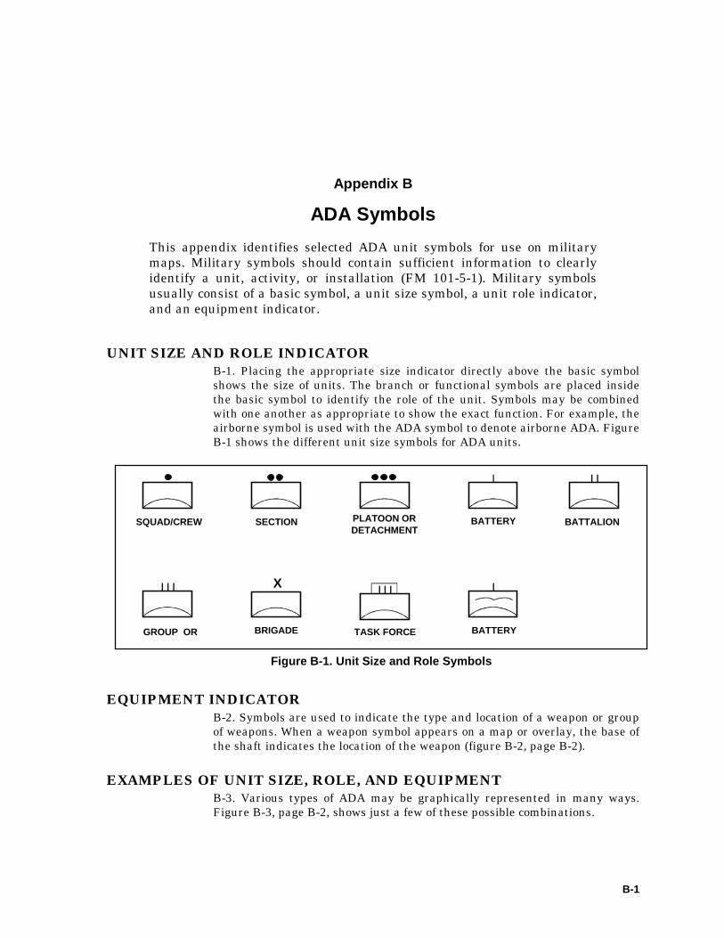
B-1
Appendix B
ADA SymbolsThis appendix identifies selected ADA unit symbols for use on militarymaps. Military symbols should contain sufficient information to clearlyidentify a unit, activity, or installation (FM 101-5-1). Military symbolsusually consist of a basic symbol, a unit size symbol, a unit role indicator,and an equipment indicator.
UNIT SIZE AND ROLE INDICATORB-1. Placing the appropriate size indicator directly above the basic symbolshows the size of units. The branch or functional symbols are placed insidethe basic symbol to identify the role of the unit. Symbols may be combinedwith one another as appropriate to show the exact function. For example, theairborne symbol is used with the ADA symbol to denote airborne ADA. FigureB-1 shows the different unit size symbols for ADA units.
EQUIPMENT INDICATORB-2. Symbols are used to indicate the type and location of a weapon or groupof weapons. When a weapon symbol appears on a map or overlay, the base ofthe shaft indicates the location of the weapon (figure B-2, page B-2).
EXAMPLES OF UNIT SIZE, ROLE, AND EQUIPMENTB-3. Various types of ADA may be graphically represented in many ways.Figure B-3, page B-2, shows just a few of these possible combinations.
X
SQUAD/CREW SECTION PLATOON ORDETACHMENT
BATTERY BATTALION
GROUP OR BRIGADE TASK FORCE BATTERY
Figure B-1. Unit Size and Role Symbols
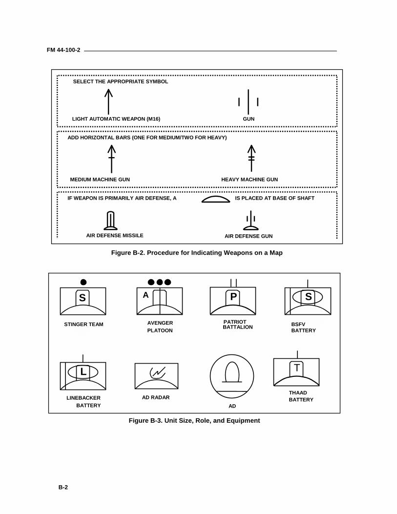
FM 44-100-2
B-2
LIGHT AUTOMATIC WEAPON (M16) GUN
SELECT THE APPROPRIATE SYMBOL
AIR DEFENSE MISSILE AIR DEFENSE GUN
IF WEAPON IS PRIMARILY AIR DEFENSE, A IS PLACED AT BASE OF SHAFT
MEDIUM MACHINE GUN HEAVY MACHINE GUN
ADD HORIZONTAL BARS (ONE FOR MEDIUM/TWO FOR HEAVY)
Figure B-2. Procedure for Indicating Weapons on a Map
S PA S
L
STINGER TEAM AVENGERPLATOON
PATRIOTBATTALION BSFV
BATTERY
LINEBACKERBATTERY
AD RADARAD
T
THAADBATTERY
Figure B-3. Unit Size, Role, and Equipment
Glossary-1
GlossaryA2C2AAA
AADCAAMDC
AARABCS
ABMOCABTACAACCACOACRACV
ADADA
ADCNADCS
ADIADIZ
ADLNOADOAADSIADWAEU
AGCCSAGL
AGTSAI
Air DefenseArtillery
army airspace command and controlantiaircraft artilleryarea air defense commanderarmy air and missile defense commandafter action reviewarmy battle command systemair battle management operations centerair breathing threatairspace control authorityair component commanderairspace control orderarmored cavalry regimentantenna cable vehicleair defenseair defense artilleryair defense coordination netair defense coordination sectionair defense interfaceair defense identification zoneair defense liaison officerair defense operations areaair defense systems integratorair defense warningantenna equipment unitarmy global command and control systemabove ground leveladvanced gunnery training systemair interdictionground-based surface-to-air weapons, for engaging air and missiletargets
FM 44-100-2
Glossary-2
air defenseoperations area
(ADOA)air interdiction
airspacemanagement
air superiority
air supremacy
ALERTALOC
AMCAMD
AMDCOORDAMDPCSAMDWS
AMGAMT
ANBACISAO
AOCAOI
AORAPC
APDS-TAPOD
APUAR
area air defenseCommander
an area and the airspace above it within which procedures areestablished to minimize mutual interference between air defenseand other operationsair operations conducted to destroy, neutralize, or delay the enemy'smilitary potential before it can be brought to bear effectively againstfriendly forcesthe coordination, integration, and regulation of the use of airspace ofdefined dimensionsthat degree of dominance in the air battle of one force over anotherthat permits the conduct of operations by the former and its relatedland, sea, and air forces at a given time and place withoutprohibitive interference by the opposing forcethat degree of air superiority wherein the opposing air force isincapable of effective interferenceattack and launch early reporting to theaterair lines of communicationsarmy materiel commandair and missile defenseair and missile defense coordinatorair and missile defense planning and control systemair and missile defense workstationantenna mast groupavenger maintenance trainerarmy nuclear, biological and chemical information systemarea of operationsair operations centerarea of interestarea of responsibilityarmored personnel carrierarmor piercing discarding sabot-traceraerial port of debarkationauxiliary power unitarmorwithin an over seas unified command, subordinate unifiedcommand, or joint task force, the commander will assign overallresponsibility for air defense to a single commander
FM 44-100-2
Glossary-3
ARMARNG
ARSPACEASASASATASCCASCM
ASGASP
ASPOATACMS
ATCCSATDL
ATGATGM
ATOATP
AVAVT
AWACSA2C2BAS
BATSbattlefield air
interdictionbattlefield
coordinationdetachment
BCDBCE
BCISBCUBde
antiradiation missilearmy national guardarmy space commandall source analysis systemanti-satellite systemarmy service component commanderanti ship cruise missilearea support groupammunition supply pointarmy space program officearmy tactical missile systemarmy tactical command and control systemarmy tactical data linkantenna/transceiver groupanti-tank guided missileair tasking orderallied tactical publicationaviationautomatic video trackerairborne warning and control systemarmy airspace command and controlbattalion aid stationballistic aerial target systemair interdiction attacks against targets which are in a position tohave a near term effect on friendly land forcesthe army liaison element collocated with the JAOC which processesland forces' requests for tactical air support, monitors and interpretsthe land battle situation for the JAOC, and provides the necessaryinterface for the exchange of current intelligence and operationaldatabattlefield coordination detachmentbradley control electronicsbattlefield combat identification systembattery coolant unitbrigade
FM 44-100-2
Glossary-4
BFVBIT
BITEBM
BMMOBM/C3I
BM/C4I
BMEBMG
BNBRUBSA
BSFVBSG
C2C2WC3IC4I
CADCICAFAD
CAPCASCAU
CCIRCDI
CDOPSCdr
CDRUSELM-NORAD
CDTCEPCEU
bradley fighting vehiclebuilt-in testbuilt-in test equipmentbattle managementbattalion motor maintenance officerbattle management and command, control, communications andintelligencebattle management and command, control, communications,computers and intelligencebattalion maintenance equipmentbattery maintenance groupbattalionbattery replaceable unitbrigade support areabradley stinger fighting vehiclebeam steering generatorcommand and controlcommand and control warfarecommand, control, communications and intelligencecommand, control, communications, computers, and intelligencecommon air defense communications interfacecombined arms for air defensecombat air patrol; crises action proceduresclose air supportcrew access unitcommander’s critical information requirementsclassification, discrimination and identificationcoherent doppler scorercommanderCommander, United States Element-North American AerospaceDefense Commandcontrol display terminalcircular error probablecooling equipment unit
FM 44-100-2
Glossary-5
CFTCHS
CINCCINCNORAD
CIUCJCSCLET
close air support(CAS)
CMCMMC
CNRCOA
COCOMCOFACOFT
COMARSPACECommand
Command andControl
COMMCOMMZ
COMSECControl
CONUS
captive flight trainercommon hardware softwarecommander in chiefCommander In Chief, North American Aerospace DefenseCommandcontrol interface unit/communications interface unitchairman, joint chiefs of staffcooling liquid electronic tubeair action against hostile tar gets which are in close proximity tofriendly forcescruise missilecorps materiel management centercombat net radiocourse of actioncombatant commandcorrelation of forces-airconduct of fire trainerCommander, United States Army Space CommandThe authority that a commander in the military service lawfullyexercises over subordinates by virtue of rank or assignment.Command includes the authority and responsibility for effectivelyusing available resources and for planning the employment of,organizing, directing, coordinating, and controlling military forcesfor the accomplishment of assigned missions. it also includesresponsibility for health, welfare, morale, and discipline of assignedpersonnel.The exercise of authority and direction by a properly designatedcommander over assigned forces in the accomplishment of themission. Command and control functions are performed through anarrangement of personnel, equipment, communications, facilities,and procedures employed by a commander in planning, directing,coordinating, and controlling forces and operations in theaccomplishment of the mission.communications vancommunications zonecommunications securityauthority less than full command exercised by a commander overpart of the activities of subordinate or other organizationscontinental united states
FM 44-100-2
Glossary-6
COSCOMcounterairoperations
CPCPUCRCCRGCRPCSACSGCSRCSS
CSSCSCSTCTC
Cueing
CZDA
DACSDAMDAODCA
DCSOPSDEFCON
DefensivecounterairDEM/VAL
DISDISCOM
DISEDLADLTDLU
corps support commandair operations conducted to attain and maintain a desired degree ofair superiority by the destruction or neutralization of enemy aircommand postcontrol processing unitcontrol and reporting centercommunications relay groupcontrol and reporting postcorps storage areacorps support groupcontrol supply ratecombat service supportcombat service support control systemcrew station trainercombined training centerproviding timely position data and with tentative identification ofaircraft within a designated range of a fire unitcombat zonedepartment of the armydivert attitude control systemdisplay aided maintenancedivision ammunition officerdefensive counter airdeputy chief of staff for operations and plansdefense readiness conditionthe protection of assets from air attack through both direct defenseand destruction of the enemy's air attack capacity in the airdemonstration and validationdistributive interactive simulationdivision support commanddeployable intelligence support elementdefense logistics agencydata link terminaldata link unit
FM 44-100-2
Glossary-7
DMSPDOD
DPDS
DSADSCS
DSCSOCDSMCDNVT
DSPDSS-1DSVT
EE3A
EAEAC
ECCMECMECSECUEDREEFIEEUEHFEIU
electronic attack
electronic warfare
EMCONEMI
EMPEN
defense meteorological satellite programdepartment of defensedecision pointdirect supportdivision support areadefense satellite communications systemdefense satellite communications system operation centerdirect support maintenance companydigital non-secure voice terminaldefense support program/direct support platoondigital small switchdigital secure voice terminaleastNavy AWACS aircraftelectronic attackechelons above corpselectronic counter countermeasureselectronic countermeasuresengagement control stationequipment coolant unitembedded data recorderessential elements of friendly informationelectronic equipment unitextremely high frequencyexternal interface unitthat division of electronic warfare involving actions taken to preventor reduce an enemy's effective use of the electromagnetic spectrummilitary action involving the use of electromagnetic energy todetermine, exploit, reduce, or prevent hostile use of theelectromagnetic spectrum and action which retains friendly use ofthe electromagnetic spectrumemissions controlelectromagnetic interferenceelectromagnetic pulsecorps of engineers
FM 44-100-2
Glossary-8
engage
EOEOD
EOSATEP
EPLRSEPPEPU
ERINTEROS
ERTESET
ETPTEW
EWCCEWOPS
FAFAADFARP
FAXFCCFDC
FEBAFEZ
FFIRFHTFID
fire supportcoordinator(FSCOORD)fire support
element (FSE)
a command order used to direct surface-to-air units to engagespecific targets with intent to destroyengagement operationsexplosive ordnance disposalearth observation satelliteelectronic protectionenhanced position location reporting systemelectric power plantelectric power unitextended range interceptorearth resources observation systemempty round trainerelectronic warfare supportembedded trainerembedded troop proficiency trainerelectronic warfareexpanded weapons control computerelectronic warfare operationsfield artilleryforward area air defenseforward area rearm/refuel pointfacsimileflight control centerfire direction centerforward edge of the battle areafighter engagement zonefriendly forces information requirementsfield handling trainerforeign internal defensethe individual responsible for the planning and execution of fires sothat targets are adequately covered by a suitable weapon or group ofweaponsA functional element of a force command post that providescentralized targeting, coordination, and integration of fires deliveredon surface targets by fire support means under the control of or insupport of the force. This element is staffed from the field artillery
FM 44-100-2
Glossary-9
FLIRFLOT
FLTSATFLTSATCOM
FMFO
FOCFOFTFOPS
FOSFOV
FRAGOFROG
FSFSB
FSCOORDFSEFSTFUFWG1G2G3G4
GCIGEMGFE
GMFSCGMT
GPFUGPS
GS
headquarters or field artillery staff section of the force andrepresentatives of other fire support means.forward-looking infrared receiverforward line of own troopsfleet satellitefleet satellite communication systemfield manualforce operationsflight operations centerforce-on-force trainerfuture operations vanfiber optic systemfield of viewfragmentary orderfree rocket over groundfire supportforward support battalionfire support coordinatorfire support elementfinance support teamfire unitfixed wingassistant chief-of-staff, personnelassistant chief-of-staff, intelligenceassistant chief-of-staff, operations and plansassistant chief-of-staff, logisticsground control interceptionguidance enhanced missilegovernment furnished equipmentground mobile forces satellite communicationsguided missile transporter / Greenwich mean timegas particulate filter unitglobal positioning systemgeneral support
FM 44-100-2
Glossary-10
GS-RGSA
HEHEI-T
HEMTTHF
HHBHIDACZHIMAD
HMMWVHQDA
HRVHSS
HzIAPIBS
ICBMICC
ICOFTICOMS
ICSID
IEAIEWIFFIFVILS
IMETSIMT
IMTSIN
INTELintelligence
preparation of the
general support-reinforcinggeneral services administrationhigh explosivehigh explosive incendiary-tracerheavy expanded mobility tactical truckhigh frequencyheadquarters and headquarters batteryhigh-density airspace control zonehigh- to medium-altitude air defensehigh mobility multipurpose wheeled vehicleHeadquarters, Department of the Armyhigh resolution visiblehealth service supporthertzintegrated avionics packageintelligence broadcast systemintercontinental ballistic missileinformation and coordination centralinstitutional conduct of fire trainerintegrated communications securityintercommunication systemidentificationinterface electronic assemblyintelligence and electronic warfareidentification, friend or foeinfantry fighting vehicleintegrated logistics supportintegrated meteorological systeminstitutional maintenance trainerimproved moving target simulatorinfantryintelligencea continuous, integrated, and comprehensive analysis of the effectsof terrain, weather, and enemy capabilities on operations
FM 44-100-2
Glossary-11
battlefieldINTERCOM
IOSIOT&E
IPBIR
IRBMIR/NUV
ISUJ3
JAOCJCSJDNJEZ
JFACCJFC
JFLCCJFMCC
JFSOCCJICOJOA
Joint Force AirComponent
Commander(JFACC)
Joint Force LandComponent
Commander(JFLCC)
JOPESJOTS
JRAJSN
JSOA
intercommunicationsinstructor operator stationinitial operational test and evaluationintelligence preparation of the battlefieldinfrared radiation/intelligence requirementintermediate-range ballistic missileinfrared/negative ultravioletintegrated sight unitoperations directoratejoint air operations centerjoint chiefs of staffjoint data netjoint engagement zonejoint force air component commanderjoint force commanderjoint force land component commanderjoint force maritime component commanderjoint force special operations component commanderjoint interface control officerjoint operations areaThe joint force air component commander's responsibilities will beassigned by the joint force commander (normally these wouldinclude, but not be limited to, planning, coordination, allocation, andtasking based on the joint force commander's appointment decision).The designated senior land commander in a joint force who exercisescommand and control of all assigned land forces. based upon thejoint force commander's guidance, the JFLCC develops his conceptof operations, assigns missions and allocated resources. He supportssubordinate units by conducting joint planning and coordination toimplement their schemes of maneuver.joint operations planning and execution systemjoint operations tactical systemjoint rear areajoint surveillance netjoint special operations area
FM 44-100-2
Glossary-12
JSTARSJTADSJTAGS
JTAMDJTAR
J-TENSJTF
JTIDSJTMDJTOC
JTTJZkgkwkmKV
LLACMLADW
LANLANDSAT
LARLATLAW
LBLCCLCDLCRLCSLCULEALEDLID
LNO
joint surveillance and target attack radar systemjoint TADIL-A distribution systemjoint tactical ground stationjoint theater air and missile defensejoint tactical air requestjoint-tactical exploitation of national capabilitiesjoint task forcejoint tactical information distribution systemjoint theater missile defensejump tactical operations centerjoint tactical terminaljoint zonekilogramkilowattkilometerkill vehicleliterland attack cruise missilelocal air defense warninglocal area networkland satellitelogistics assistance representativelive air trainerlight antitank weaponpoundland component commanderliquid crystal displaylarge caliber rocketlaunch control stationlightweight computer unitlauncher electronic assemblylight emitting diodelight infantry divisionliaison officer
FM 44-100-2
Glossary-13
LOCLOSLRCLRF
LRPTLRU
LSLSA
LSDISLSMU
LZMAGTF
MANPADSMAP
MARFORCCMC
MCDMCOMCSMCTMEFMEI
METT-TC
MEZMHz
MICCMILES
MILSATCOMMLRSMMC
MOETMOPP
MOS
lines of communications (logistic routes)line of sightlogistics readiness centerlaser range finderlarge repair parts transporterline replaceable unitlaunching stationlogistics support analysislight and special division interim sensorlauncher and sensor mockuplanding zonemarine air ground task forcemanportable air defense systemmission application programmarine force component commandermaintenance centermissile countermeasure devicemovement control officermaneuver control systemmovement control teammarine expeditionary forcemajor end itemsmission, enemy, terrain and weather, troops and support available,time available, and civil considerationsmissile engagement zonemegahertzmaster information and coordination centralmultiple integrated laser engagement simulatormilitary satellite communicationsmultiple-launch rocket systemmateriel management centermarch order and emplacement trainermission oriented protective posturemilitary occupational specialty
FM 44-100-2
Glossary-14
MPCMPH
MRBMMREMRLMRP
MRPTMRRMRTMSBMSEMSI
MSRMTOE
MTWMWR
NNAI
NASANATO
NAVCCNBCNCANEONGO
NICPNMD
NORADNTC
NTDSOAC
OBOCA
OCOKA
message processing centermiles per hourmedium range ballistic missilemeals ready to eatmultiple rocket launchermissile round palletmissile round pallet trainerminimum risk routemissile round trainermain support battalionmobile subscriber equipmentmultispectral imagerymain supply route/missile simulation roundmodified table of organization and equipmentmajor theater warmorale, welfare, and recreationnorthnamed area of interestnational aeronautics and space administrationNorth Atlantic Treaty Organizationnavy component commandernuclear, biological, and chemicalnational command authoritynoncombatant evacuation operationsnon-government organizationnational inventory control pointnational missile defensenorth American aerospace defense commandnational training centernaval tactical data systemofficers advanced courseorder of battleoffensive counterairobservation, cover and concealment, obstacles, key terrain, and
FM 44-100-2
Glossary-15
offensivecounterair
OCUODDOICOLS
OOTWOP
OPCONoperational
command
operationalcontrol
operational levelof war
operationssecurity (OPSEC)
OPLANOPORDOPSEC
ORFOSI
PACPADILPADS
PAOpassive air
defense
PASRPCOFT
avenues of approachan operation mounted to destroy, disrupt, or limit enemy air powerclose to its source as possibleoperator control unitoptical disk driveofficer in chargeoperational linescan systemoperations other than warobservation postoperational controlthose functions of command involving the composition ofsubordinate forces, the assignment of tasks, the designation ofobjectives, and the authoritative direction necessary to accomplishthe missionsynonymous with operational command
the level of war at which campaigns and major operations areplanned, conducted, and sustained to accomplish strategic objectiveswithin theaters or areas of operationsthe process of denying adversaries information about friendlycapabilities and intentions by identifying, controlling, andprotecting indicators associated with planning and conductingmilitary operations and other activitiesoperation planoperation orderoperations securityoperational readiness floatoperator system interfacepatriot advanced capabilitiespatriot digital information linkposition and azimuth determining systempublic affairs officerAll measures, other than active defense, taken to minimize theeffects of hostile air action. These include the use of tactical warningof air or missile attack, cover, concealment, camouflage, deception,dispersion, and protective construction.personnel accounting and strength reportingpatriot conduct of fire trainer
FM 44-100-2
Glossary-16
PDUPGS
PIMITPIR
PJHIPLGR
PLLPLS
PMCSPODPOIPOL
POMTpositive control
PPIPPSPPUPRM
procedural control
PSSPTLPub
PZR
R&SRADC
RCRCMAT
RCSRCTRCU
power distribution unitprecision gunnery systempatriot intermediate maintenance instructional trainerpriority intelligence requirementPLGR/JTIDS hybrid interfaceprecision lightweight global positioning system receiverprescribed load listpalletized load systempreventive maintenance checks and servicesport of debarkationprogram of instructionpetroleum, oils and lubricantspatriot organizational maintenance trainera method of airspace control that relies on positiveidentification, tracking, and direction of aircraft within an airspace,conducted with electronic means by an agency having this authorityand responsibility thereinplanned position indicatorprecision positioning systemprimary power unitpersonnel readiness managementa method of airspace control that relies on a combination ofpreviously agreed and promulgated orders and procedurespersonnel system supportprimary target linepublicationpick-up zonereinforcingreconnaissance and surveillanceregion air defense commanderreserve componentradio controlled miniature aerial targetradar cross sectionremote control terminalremote control unit
FM 44-100-2
Glossary-17
RFRFI
remotely-pilotedvehicle (RPV)
RLRIURMPROE
ROTCROWRPMRPV
RPVTSRRTR&S
RSRSI
RSOPRSTARSOIRSR
RTRTO
rules ofengagement (ROE)
RWRWCIU
RWRRWS
SS1S2S3S4
radio frequencyradio frequency interferenceAn unmanned aerial vehicle capable of being controlled by a personfrom a distant location through a communications link. It isnormally designed to be recoverable.routing logic radio interface unitreprogrammable microprocessorrules of engagementreserve officer training corpsrest of worldrevolutions per minuteremotely piloted vehicleremotely piloted vehicle trainer stationradio relay terminalreconnaissance and surveillanceradar setradio subsystem interfacereconnaissance, selection, and occupation of positionreconnaissance, surveillance, and target acquisitionreception, staging, onward-movement and integrationrequired supply ratereturn to duty/radio terminalradiotelephone operatorDirectives that delineate the circumstances under which weaponsmay fire at an aerial threat.rotary wingradar weapons control interface unitradar warning receiverrigid wall sheltersecret/southadjutantintelligence officeroperations and training officerlogistics officer
FM 44-100-2
Glossary-18
SAMSATCOM
SCBSDCSDI
SDPSDU
SEADSENSEPSHF
SHORADSHORADEZ
SHTUSIAPSICC
SICPSSIF
SIGOSIMT
SINCGARSSJA
SLBMSLC
SMUSOCSOESOFSOJ
SOJCSOPSOR
SPACECOMSPOD
surface to air missilesatellite communicationsstinger control boxstrategic defense commandstrategic defense initiativesignal data processorstinger distribution unitsuppression of enemy air defensessmall extension nodespherical error probablesuper high frequencyshort-range air defenseshort-range air defense engagement zonesimplified hand held terminal unitsingle integrated air picturesubordinate information and coordination centralstandardized integrated command post systemselective identification featuresignal officersentinel institutional maintenance trainersingle channel ground and airborne radio systemstaff judge advocatesea-launched ballistic missileside lobe cancellerswitch multiplexer unitsector operations centerstate of emissionsspecial operation forcesstand off jammerstand off jammer countermeasuresstanding operating procedurestate of readinessspace commandsea port of debarkation
FM 44-100-2
Glossary-19
SPOTSPINSSRBMSRPT
SSCSSDC
SSISTL
STPTstrategic level of
war
STSSTU
suppression ofenemy air
defenses (SEAD)SVM
SVMLTAA
TAAMDCOORDTACC
TACDARtactical air control
center (TACC)
tactical level ofwar
TADILTADSS
TAITASM
TBMTCATCO
systeme probatoire d'observation de la terrespecial instructionsshort range ballistic missilesmall repair parts transportersmall scale contingenciesspace and strategic defense commandsensor system interfacesecondary target linestinger troop proficiency trainerthe level of war at which a nation or group of nations determinesnational or alliance security objectives and develops and usesnational resources to accomplish those objectivessentinel training systemsecure telephone unitthat activity which neutralizes, destroys, or temporarily degradesenemy air defenses in a specific area by physical attack and orelectronic warfarestinger vision modulestandard vehicle missile launchertactical assembly areatheater army air and missile defense coordinatortactical air control centertactical detection and reportingthe principal air operations installation (land- or ship-based) fromwhich all aircraft and air warning functions of tactical airoperations are controlledthe level of war at which battles and engagements are planned andexecuted to accomplish military objectives assigned to tactical unitsor task forcestactical digital information linktraining aids, devices, simulators and simulationstarget area of interesttactical air-to-surface missiletactical/theater ballistic missiletactical control assistanttactical control officer
FM 44-100-2
Glossary-20
TCSTD
TDATDDS
TELTENCAPTERCOM
TERSTES
TFTHAAD
THTTIBS
TMTMD
TMDETNMC
TNTTOCTOW
TPTPT
TRANSCOMTRAP
TSATSGTST
TSVCTTTTTYTVCTVMUAV
UCOFT
tactical command systemtactical directortactical director assistanttactical-related applications data distribution systemtransporter erector launchertactical exploitation of national capabilitiesterrain contour matchingtactical event reporting systemtactical event systemtask forcetheater high altitude area defensetracking head trainertactical information broadcast servicetechnical manual/theater missiletheater missile defensetest, measuring and diagnostic equipmenttactical network mission centertroop netted trainertactical operations centertube-launched, optically-tracked, wire guided (missile)tactical plannertroop proficiency trainertransportation commandtactical related applicationstheater storage areatactical station grouptroop subordinate trainerthrough sight video cameratable top trainerteletypethrust vector controltrack via missileunmanned aerial vehicleunit conduct of fire trainer
FM 44-100-2
Glossary-21
UHFUPS
USUSA
USAADASCHUSAF
USEUCOMUSCINCSPACE
USMCUSMTF
USNUSPACOM
USSPACECOMUSTRANSCOM
UVVHF
VSTTW
WADWANWCSWEZ
WMDXO
ultrahigh frequencyuninterruptible power supplyUnited StatesUnited States ArmyUnited States Army Air Defense Artillery SchoolUnited States Air ForceUnited States European CommandUnited States Commander In Chief, Space CommandUnited States Marine CorpsUnited states marine task forceUnited States NavyUS Pacific CommandUnited States Space Commandunited states transportation commandultravioletvery high frequencyvariable speed training targetwestweapons alert designatorwide area networkweapon control statusweapon engagement zoneweapons of mass destructionexecutive officer

FM 44-100-2
Glossary-22
BLANK
Bibliography-1
Bibliography1
FM 40-1. Joint Tactical Ground Station Operations. 9 September 1999.2
FM 44-3. Air Defense Artillery Employment Stinger. 15 June 1984.3
FM 44-3. Air Defense Artillery Employment Stinger. 15 June 1984.4
FM 44-12. Multi-Service Procedures for Airborne Warning and Control5System Ground-Based Air Defense Operations. 30 September 1993.6
FM 44-16. Stinger Platoon Combat Operations. 29 May 1987.7
FM 44-18-1. Stinger Team Operations. 31 December 1984.8
FM 44-44. Avenger Platoon Squad Operations. 3 October 1995.9
FM 44-46. MANPADS Platoon and Section Operations. December 96.10
FM 44-64. SHORAD Battalion and Battery Operations. 05 June 1997.11
FM 44-85. Patriot Battalion and Battery Operations. 21 February 1997.12
FM 44-85-1. Patriot Tactics, Techniques and Procedures. 1 November 1995.13
FM 44-94. AAMDC Operations. 31 March 2000.14
FM 44-100. US Army Air Defense Operations. 6 March 2000.15
FM 100-5. Operations. 14 June 1993.16
FM 100-12. Army Theater Missile Defense Operations. 31 March 2000.17
FM 100-103. Army Airspace Command and Control in a Combat Zone.187 October 1987.19
FM 101-5-1. Operational Terms and Graphics. 30 September 1997.20
FY 00. Air and Missile Defense Master Plan. 15 October 1999.21
ST 44-85-3. Patriot Advanced Capability-3 Doctrine and Tactics Impact22Package. 19 May 1999.23
TM 9-1425-429-12. Operator's and Organizational Manual: Stinger Guided24Missile System. 21 April 1992.25
TM 9-1425-600-12. Operator's and Organizational Maintenance Manual26System Description Patriot Air Defense Guided Missile System.2730 December 1994.28
TM 9-2350-252-10-2. Operator's Manual Fighting Vehicle Infantry M2, M2Al29and Fighting Vehicle Cavalry M3, M3AI. 22 September 1986.30
TM 11-5820-890-10-1. Operator's Manual for Radio Sets, AN/PRC-119,31AN/VRC-87, AN/VRC-88, AN/VRC-89, AN/VRC-91, AN/VRC-9232(SINCGARS). 1 March 1988.33
34
Index-1
IndexA
ADSI, 6-4, 6-5Aerial targets, 7-1, 7-14 thru 7-17
Ballistic aerial target system(BATS), 7-17
BQM-34 Firebee, 7-14 thru7-16
MQM-107 Streaker, 7-14thru 7-16
Multiple integrated laserengagement system(MILES), 7-5, 7-6, 7-15
Radio-controlled miniatureaerial target (RCMAT),7-17
Remotely piloted vehicletarget system (RPVTS),7-1
Stinger, 3-7TOW (employment against),
3-9Agility, 1-2Air Defense Artillery
Employment guidelines, A-2Employment principles, A-1Forces, 1-1Mission, 1-1Relation to Army tenets, 1-2Symbols, B-1, B-2Threat, 1-1, 2-1
Air and Missile Defense, 1-1 thru1-4, 2-4, 2-5
Battle commandorganization, 6-1, 6-2
Combat function, 1-3Force protection, 1-3Relation to Army tenets, 1-2,
1-3Air and Missile Defense Planning
and Control System (AMDPCS),6-1 thru 6-6, 6-14
Air and missile defenseworkstation, 6-2, 6-6
Air defense systemintegrator (ADSI), 6-4, 6-5
All source analysis system(ASAS), 6-5
Maneuver control system(MCS), 6-5
Air and missile defenseworkstation (AMDWS), 6-2, 6-4,6-6
Air battle management operationscenter (ABMOC), 6-7, 6-8, 6-10,6-13
Airborne Warning and ControlSystem (AWACS), 6-6, 6-7, 6-10
All source analysis system, 6-5AN/FSQ-187, Improved moving
target simulator (IMTS), 7-1, 7-3,7-4
Antenna element task trainer, 7-8,7-10
Antenna equipment, 4-1, 4-2Antenna mast group (AMG), 5-1
thru 5-5, 5-10Army Airspace Command and
Control (A2C2), 6-3, 6-7, 6-10,6-13, 6-14, 7-8
Army Air and Missile DefenseCommand (AAMDC), 6-1, 6-2,6-4
Avenger weapon system, 3-14thru 3-17
Communications equipment,3-15
Forward looking infraredreceiver (FLIR), 3-14 thru3-16, 7-7
Gunner’s station, 3-15HMMWV characteristics,
3-15, 5-11, 6-10Interrogator Friend or Foe
(IFF), 3-14 thru 3-16Laser range finder (LRF),
3-14 thru 3-16Machine gun M3P, 3-14,
3-15Remote control unit (RCU),
3-15Reticules, 3-16
Sensor system, 6-7, A-1System description, 3-14
thru 3-16Training devices, 7-6, 7-7
Captive flight trainer, 7-6Force-on-force trainer,
7-4, 7-6Institutional Conduct of
Fire trainer (ICOFT),7-6
Table top trainer (TTT),7-6, 7-7
Troop proficiency trainer(TPT), 7-6, 7-7
Turret, 3-14 thru 3-16, 7-7B
Balanced fires, A-2, A-3Ballistic aerial target system
(BATS), 7-17Battery coolant unit (BCU), 3-4,
3-6, 3-15, 7-1Battle command organizations,
AMD, 6-1, 6-2Command post (CP), 6-1,
6-2Fire Direction Center (FDC),
2-6, 5-1, 6-1, 6-2Tactical Operations Center
(TOC), 4-7 thru 4-9, 4-15,5-10, 5-12, 5-14, 6-1, 6-2,6-7, 7-8
Battle management command,control, communications andintelligence (BM/C3I), 4-1, 4-5thru 4-7, 4-10, 4-12, 7-12
Bradley Stinger Fighting Vehicle(BSFV), 3-8 thru 3-11, 6-7, 6-10,7-4
Employment, 3-6, 3-7, 3-10,3-11
Machine gun M240C, 3-10Main gun M242, 3-9System description, 3-8 thru
3-14System characteristics, 3-8,
3-9
FM 44-100-2
Index-2
TOW missile, 3-9, 7-4Training devices, 7-4, 7-5
Bradley missilesimulation round(MSR), 7-4, 7-5
Crew station trainer, 7-4Force-on-force trainer
(FOFT), 7-4, 7-6ICOFT, 7-4Precision gunnery
system (PGS), 7-4, 7-5Thru sight video camera
(TSVC), 7-4, 7-5UCOFT, 7-4
Brigade TOC, 5-10, 6-2Communications and
navigation equipment, 5-5Fire direction center (FDC),
6-2Jump tactical operations
center (JTOC), 6-2C
Canister, guided missile (Patriot),5-7
Canister, missile (THAAD), 4-8,4-9
Command Post (CP), 3-7, 4-16,6-10
Battle command organizations, AMD, 6-1, 6-2FAAD/C3I system, 7-8functions, 6-1
Communications relay group(CRG), 5-1 thru 5-3, 5-5, 5-10,5-10, 5-13
Communications system tasktrainer, 7-8, 7-9
Conduct of fire trainer, Patriot(PCOFT), 7-8, 7-9
Cooling equipment unit (CEU),4-1, 4-3, 4-4, 7-12, 7-13
Cooling equipment unit trainer,7-13
Cooling liquid tube removal andreplacement task trainer, 7-8,7-10
D
Data link upgrade task trainer,7-8, 7-9
Defense in depth, A-2, A-3Depth, 1-2Digital non-secure voice terminal
(DNVT), 4-6, 4-15, 6-7, 6-8Digital secure voice terminal
(DSVT), 4-15, 5-13, 6-7, 6-8E
Early engagement, 3-7, 3-13, A-2Electric power plant, EPP III, 5-3,
5-5Electronic equipment unit (EEU),
4-1 thru 4-5, 7-13Electronic equipment unit trainer,
7-13Embedded data recorder, 5-4Employment guidelines, ADA, A-2Employment principles, ADA, A-1Empty round trainer (ERT), 7-8,
7-11Enhanced position location
reporting system (EPLRS), 3-13,3-15, 6-7 thru 6-10, 6-12
Engagement Control Station(ECS), 5-3 thru 5-7, 5-10, 5-16,6-6, 7-8 thru 7-10
Explosive ordnance disposaltrainer, THAAD, 7-11, 7-12
FFAAD C3I system, 6-6 thru 6-8
A2C2, 6-3, 6-7, 6-10, 6-13, 6-14, 7-8ABMOC, 6-7, 6-8, 6-10, 6-13Command and control, 6-1
thru 6-3, 6-5, 6-7, 6-9, 6-10Command post, 7-8Communications, 6-8 thru
6-10Enhanced position
location reportingsystem (EPLRS), 6-8thru 6-10, 6-12
Joint tactical informationdistribution system(JTIDS), 6-5, 6-7 thru6-10
Mobile subscriberequipment (MSE), 4-6,4-14, 4-15, 4-17, 5-11thru 5-13, 6-7 thru 6-9
SINCGARS, 6-7 thru6-10, 6-12
Components, 6-7, 6-8Intelligence, 6-7, 6-8Sensors, 6-7, 6-8, 6-10
Light and special divisioninterim sensor (LSDIS),6-7, 6-10
Sentinel, 6-7, 6-10 thru6-12
Sensor/C2, 6-7, 6-8Field handling trainer (FHT), 7-1,
7-2Fire Direction Center (FDC), 2-6,
5-1, 6-1, 6-2Firebee, BQM-34, 7-14 thru 7-16FLIR (forward looking infrared
receiver), 3-14 thru 3-16, 7-7Force on force trainer (FOFT),
7-4, 7-6Forward area air defense
command controlcommunications andintelligence, 6-6
GGas Particulate Filter Unit
(GPFU), 4-5, 5-2Generator, 10 kW, 4-9, 6-10Generator, 15 kW, 4-5, 5-7, 5-18Generator, 150 kW, 5-5Generator, PU-801, 4-5, 4-6Generator, PU-802, 4-7Geopolitical assets, 1-1, 2-1Gripstock assembly, 3-2, 3-4Guided missile transporter, 5-18
HHEMTT (heavy expanded mobility
tactical truck), 5-4 thru 5-6, 5-18,7-13
HIMAD, 3-6Horizontal interaction, 1-3
FM 44-100-2
Index-3
IImproved moving target simulator
(IMTS) AN/FSQ-187, 7-1, 7-3Institutional maintenance trainer
(IMT), 7-7, 7-11, 7-12Information and coordination
central (ICC), 5-1 thru 5-3, 5-5,5-10, 5-11, 5-14 thru 5-16, 6-6,7-9
Initiative, 1-1, 1-2Institutional conduct of fire trainer
(THAAD), 7-11Integration, 1-4, 7-11, A-1, A-2Intermediate maintenance
instructional trainer, 7-8, 7-11Interrogator Friend or Foe (IFF),
3-1, 3-4 thru 3-6, 3-12 thru 3-14,3-16
JJoint radio operator and
maintenance proceduressimulator (JROMPS), 7-13
Joint tactical informationdistribution system (JTIDS), 4-8,4-13, 5-10 thru 5-12, 6-5, 6-7thru 6-10, 7-13
LLarge repair parts transporter,
5-17, 5-18Laser range finder (LRF), 3-14
thru 3-16Launch tube assembly, 3-3Launching station (LS), 5-3, 5-6,
5-7, 5-10, 5-16Launcher (THAAD), 4-8, 4-9,
4-12, 4-16, 4-18, 7-11, 7-12M
M1075 Truck, 4-8M240C machine gun, 3-10M242 main gun, 3-9M3P machine gun, 3-14, 3-15M983 Truck, 5-4, 5-6M977 Truck, 5-3, 5-5, 5-18Machine gun, 3-8, 3-10, 3-14 thru
3-16Maneuver control system, 6-5
March order and emplacementtrainer (MOET), 7-8, 7-9, 7-11,7-13
March order and emplacementtrainer, radar set (RS MO&E),7-9
Mass, 3-11Master Information and
coordination central, 6-6MCS, 6-5METT-TC, A-1, A-3Military symbols, B-1Missile (Stinger), 3-1thru 3-7Missile (THAAD), 4-1, 4-9, 4-10,
7-12Missile round pallet, 4-8, 4-9Missile round trainer (MRT), 7-8,
7-11, 7-12Mix, A-1Mobile subscriber equipment
(MSE), 4-6, 4-14, 4-15, 4-17,5-11 thru 5-13, 6-7 thru 6-9
Mobility, 1-3, 2-2, 5-4, 6-2, 6-11,A-1
MQM-107, Streaker, 7-14 thru7-16
Multiple integrated laserengagement system (MILES),7-5, 7-6, 7-15
Mutual support, 3-11, 3-10, A-2O
Operator control unit (OCU), 4-1,4-5
Organizational maintenancetrainer, Patriot (POMT), 7-8 thru7-10
Overlapping fires, 3-7, A-2P
Patriot missile system, 5-1 thru5-19
Antenna mast group (AMG), 5-1 thru 5-5, 5-10Canister, guided missile, 5-7Communications, 5-1, 5-3
thru 5-5, 5-7, 5-9 thru 5-17
Battalioncommunicationsequipment, 5-11, 5-12
Externalcommunications, 5-12,5-13
Internal communications,5-13, 5-14
Battery communicationsrequirements, 5-15,5-16
Communications relay group(CRG), 5-1 thru 5-3, 5-5,5-10, 5-10, 5-13
Electric power plant, EPP III,5-3, 5-5
Engagement Control Station(ECS), 5-3 thru 5-7, 5-10,5-16, 6-6, 7-8 thru 7-10
Gas Particulate Filter Unit(GPFU), 4-5, 5-2
Guided missile interceptaerial, 5-7 thru 5-9
Information and coordinationcentral (ICC), 5-1 thru 5-3,5-5, 5-10, 5-11, 5-14 thru5-16, 6-6, 7-9
Launching station (LS), 5-3,5-6, 5-7, 5-10, 5-16
Logistics (supply,maintenance) support,5-16
Master information andcoordination central(MICC), 6-1, 6-6
Mission, 5-1, 5-8, 5-11Radar set, 7-8, 7-9System description,
battalion, 5-1 thru 5-3System description, battery,
5-3 thru 5-9System operational
overview, 5-9 thru 5-16Target engagement
sequence, 5-9, 5-10Training devices, 7-1 thru
7-13Antenna element task
trainer, 7-8, 7-10
FM 44-100-2
Index-4
Communications systemtask trainer, 7-8, 7-9
Conduct of fire trainer(PCOFT), 7-8, 7-9
Cooling liquid tuberemoval andreplacement tasktrainer, 7-8, 7-10
Data link upgrade tasktrainer, 7-8, 7-9
Embedded trainers (ET),7-8, 7-11
Empty round trainer(ERT), 7-8, 7-11
Explosive ordnancedisposal trainer, 7-8,7-11
Intermediatemaintenanceinstructional trainer,7-8, 7-11
March order andemplacement trainer,radar set (RS MO&E),7-8, 7-9
Missile round trainer(MRT), 7-8, 7-11
Organizationalmaintenance trainer(POMT), 7-8 thru 7-10
Radar frequencycomparator tasktrainer, 7-8, 7-9
Planning, A-1Prime power unit (PPU), 4-1, 4-4,
4-5Program,
Display and control, 6-13External communications,
4-17, 5-12, 5-13PU-801 generator, 4-6PU-802 generator, 4-7
RRadar (THAAD), 4-1 thru 4-4, 4-7,
4-8, 4-10 thru 4-15Radio controlled miniature aerial
target (RCMAT), 7-17
Radar frequency comparator tasktrainer, 7-8, 7-10
Radar set (Patriot), 7-8, 7-9Radar cross section (RCS), 2-2
thru 2-5, 2-5, 2-8, 7-15, 7-16RCU (remote control unit,
Avenger), 3-15Remotely piloted vehicle target
system (RPVTS), 7-1S
Sensor system interface (SSI), 4-7, 4-8, 4-13, 4-15
SINCGARS (single channelground and airborne radiosystem), 3-13, 3,15, 4-7, 4-9,4-15 thru 4-17, 5-4, 5-11 thru 5-13, 6-7 thru 6-10, 6-12, 7-9
Standardized integrated commandpost system (SICPS), 6-2, 6-7
Stinger MANPADS, 3-1, 3-8, 3-11,3-13, 6-7, 6-10, 7-1
Battery coolant unit (BCU),3-4, 3-6, 3-15, 7-1
Employment, 3-6, 3-7Gripstock assembly, 3-2, 3-4IFF, 3-1, 3-4 thru 3-7, 3-12
thru 3-16, 6-10Launch tube assembly, 3-2,
3-3Missile, 3-2, 3-11, 3-14,
3-15, 7-5, 7-6Missile round, 3-2Missile versions, 3-1Ready rack, 3-8System characteristics, 3-8,
3-9System description, 3-8Stinger team, 3-1Training devices, 7-1 thru
7-4Field handling trainer
(FHT), 7-1, 7-2Force on force trainer
(FOFT), 7-6Improved moving target
simulator (IMTS)AN/FSQ-187, 7-3
Tracking head trainer(THT), 7-1, 7-2
Troop proficiency trainer(STPT), 7-1, 7-3, 7-4
Weapon round container,3-6,
Small repair parts transporter,5-17, 5-18
Streaker, MQM-107, 7-14 thru7-16
Symbols, B-1, B-2T
Targets (see Aerial targets)Tactical operations center (TOC)
AMDPCS “jump,” 6-2brigade, 5-10defined, 6-1, 6-2division, 6-7FAAD C3I training, 7-8Patriot battalion, 5-12, 5-14,
5-15THAAD, 4-1, 4-7 thru 4-9, 4-15
Tactical operations station (TOS), 4-5, 4-6
Tactical station group (TSG), 4-7, 4-8, 4-10 thru 4-13, 4-15
Target Object Map (TOM), 4-2, 4-13
Theater High Altitude Area Defense (THAAD)
battery, 4-1, 4-7, 4-13 thru 4-17, 7-13BM/C3I, 4-1, 4-5 thru 4-7, 4-10, 4-12communications, 4-13 thru 4-18encryption devices, 4-14engagement, 4-10 thru 4-13launcher, 4-8, 4-9missile, 4-1, 4-9, 4-10, 7-12mission, 4-1operational overview, 4-10 thru 4-18ORD, 7-11radar, 4-1, 4-4, 7-13
FM 44-100-2
Index-5
system description, 4-1 thru 4-10threat, 4-1TOC, 4-1, 4-7 thru 4-9, 4-15training devices, 7-11 thru 7-13troop proficiency trainer, 7-13
Threat, 1-1 thru 1-3, 2-1 thru 2-10ADA mission, 1-1aerial reconnaissance, 1-2AMDPCS, 6-2, 6-3, 6-5artillery, 3-10assessment, 6-3ASM, 2-4, 2-5Avenger, 3-14Bradley Linebacker, 3-11class, 4-13cruise missile (CM), 2-3, 2-9,
5-8denial, 1-3ECM, 5-7evaluation, 4-10 thru 4-12electronic warfare, 2-5, 2-8,
6-14evolving, 2-1 thru 2-10, 3-1FAAD/C3I, 6-7fixed wing aircraft, 2-7 thru
2-9guidelines to counter, A-2,
A-3helicopter, 2-6, 2-7, 2-9large caliber rockets (LCR),
2-1 thru 2-3, 2-9, 2-10NBC, 2-4, 2-9Patriot, 5-1, 5-11, 6-6principles to counter, A-1,
A-2prioritization, 4-10, 4-11, A-3RSTA, 1-1, 3-14Sentinel, 6-14tactical ballistic missile
(TBM), 4-1, 4-11, 5-8THAAD, 4-1types, 1-1, 4-10
unmanned aerial vehicle(UAV), 2-5, 2-6, 2-9
weapons of massdestruction (WMD), 2-9,2-10
Tracking head trainer (THT), 7-1,7-2
Training devices, 7-1 thru 7-13Aerial targets (see Aerial
targets)Avenger, 7-6, 7-7Bradley Stinger Fighting
Vehicle (BSFV), 7-4, 7-5FAAD C3I, 7-7, 7-8Joint Radio Operator and
Maintenance ProceduresSimulator (JROMPS), 7-13
Linebacker, 7-4, 7-6Patriot, 7-8 thru 7-11Sentinel, 7-7Stinger, 7-1 thru 7-6THAAD, 7-11 thru 7-13
Troop proficiency trainer (TPT)Avenger, 7-6, 7-7C3I, 7-8Patriot, 7-11Sentinel, 7-7Stinger, 7-2THAAD, 7-13
Truck, M977, 5-3, 5-5, 5-8Truck, M983, 5-4, 5-6Truck, M1075, 4-8
VVersatility, 2-4, 2-6Vertical integration, 1-4
WWeighted coverage, A-2, A-3
FM 3-01.11 (FM 44-1-2)31 OCTOBER 2000
DISTR
Activeaccor
By Order of the Secretary of the Army:
ERIC K. SHINSEKIGeneral, United States Army
Chief of StaffOfficial:
AdmS
JOEL B. HUDSONinistrative Assistant to theecretary of the Army
0026305
IBUTION:
Army, Army National Guard, and U. S. Army Reserve: To be distributed indance with the initial distribution number 110350, requirements for FM 3-01.11.

PIN: 078610-000