Embed Size (px)
Citation preview
MaintenanceDocument
intended for professionals
To be saved for future consultation
Split integrated DHW type
Document n° 1768-3 ~ 07/03/2016
Air to Water Heat Pump
Fujitsu General (Euro) GmbHWerftstrasse 20
40549 Düsseldorf - Germany
Subject to modifications without notice.Non contractual document.
Outdoor unitWOYG112LCTAWOYG140LCTAWOYK112LCTAWOYK140LCTAWOYK160LCTA
Hydraulic unitWGYG140DG6WGYK160DG9
FR EN IT NL DE
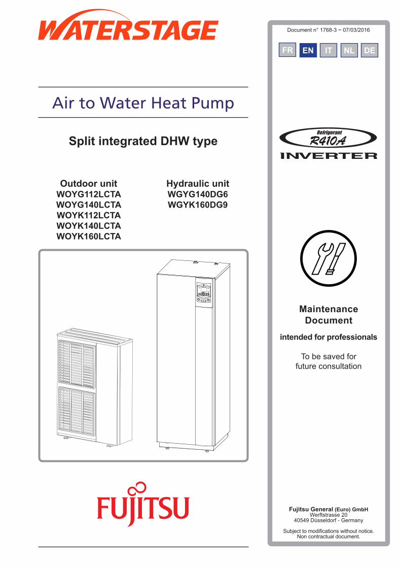
Contents
Package 4Definitions 4Specifications 5
Description 9Operating principle 10
Installation . . . . . . . . . . . . . . . . . . . . . . . . . . . . . . . . . . . 12Regulation installation and maintenance conditions 12Unpacking and reservations 12
Receipt 12Handling 12Containment of refrigerant circuits 12Accessories provided 12
Installation of refrigerant connections 13
Installation of the outdoor unit 14Installation precautions 14Outdoor unit positioning 15Condensate drain hose 15
Installing the hydraulic unit 16Installation precautions 16
Description of the unit . . . . . . . . . . . . . . . . . . . . . . . . . . . . . . 4
" This device requires for its installation, the intervention of qualified personnel with a certificate of capacity for handling refrigerants .
Refrigerant gas connection and filling the installation with gas . . . . . . 17Rules and precautions 17Shaping the refrigerant pipes 17
Bending 17Creating the flarings 17
Check and connecting 18
Filling the installation with gas 20Seal test 21Creating a vacuum 21Filling the installation with gas 22Sealing test 22Additional charge 22Pump down operation (Refrigerant collecting operation) outdoor unit 23
Hydraulic connecting . . . . . . . . . . . . . . . . . . . . . . . . . . . . . 24Connecting to the Heating circuit 24
Rinsing out the installation 24Connecting 24Volume of the heating system 25
Connecting to the DHW circuit 26Filling and purging the installation 27Thermal insulation 28Heating circulation pump speed settings 29
Installation and operating manual "1768 - EN"
Air to Water Heat Pump (Split integrated DHW type)
- 2 -
Electrical connections . . . . . . . . . . . . . . . . . . . . . . . . . . . . . 32General 32
Characteristic of the electrical supply 32General remarks on electrical connections 32 Overview of all the electrical connections 33
Cable section and protection rating 33Electrical connections on the single phase outdoor unit side 34Electrical connections on the 3- phase outdoor unit side 35
Electrical connections on the hydraulic unit side 36Outdoor sensor 40Room thermostat and/or room control unit 40
Installing a room sensor 40 Installing a room control unit 40 Fan convectors or dynamic radiators area 40
Commissioning . . . . . . . . . . . . . . . . . . . . . . . . . . . . . . . . . 40Configuring room thermostat 41
Regulation system . . . . . . . . . . . . . . . . . . . . . . . . . . . . . . . 42User interface, Room control unit (option) and Room thermostat (option) 42Description of the display 44Temperature control 44
Set to 44
Overall hydraulic layout . . . . . . . . . . . . . . . . . . . . . . . . . . . . 62
Electrical wiring diagrams . . . . . . . . . . . . . . . . . . . . . . . . . . . 64
Configuring room control unit 41
Parametering the setting 46General 46Setting parameters 46Recommended settings according to the heat emitters installation 46List of function lines (settings, diagnosis, status) 47
Troubleshooting . . . . . . . . . . . . . . . . . . . . . . . . . . . . . . . . 68Faults displayed on the hydraulic unit 68Information display 70
Faults displayed on the single phase outdoor unit 72Faults displayed on the 3-phase outdoor unit 73
Maintenance of the installation . . . . . . . . . . . . . . . . . . . . . . . . 74Hydraulic checks 74Maintenance of the DHW tank 74
Emptying the hot water tank 74Descaling 74
Checking the outdoor unit 74Electrical checks 74
Maintenance . . . . . . . . . . . . . . . . . . . . . . . . . . . . . . . . . . 75Emptying the hydraulic unit 75Distribution valve 75
ACI check 75
Quick-start procedure . . . . . . . . . . . . . . . . . . . . . . . . . . . . . 76Start-up check-list 76
Before starting-up 76Starting-up 77
Settings sheet 78Start-up data sheet 79
ErP performance values . . . . . . . . . . . . . . . . . . . . . . . . . . . . 80ErP Definition 80ErP specifications 80
Package fiche 82
Instructions for the user . . . . . . . . . . . . . . . . . . . . . . . . . . . . 83
Installation and operating manual "1768 - EN" - 3 -
Air to Water Heat Pump (Split integrated DHW type)
ERP values . . . . . . . . . . . . . . . . . . . . . . . . . . . . . . . . . . . 72
Instructions for the user . . . . . . . . . . . . . . . . . . . . . . . . . . . 81
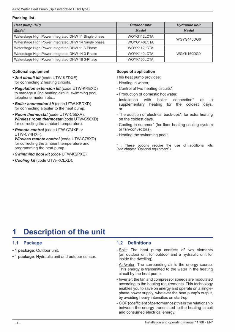
1 .1 Package• 1 package: Outdoor unit.• 1 package: Hydraulic unit and outdoor sensor.
1 .2 Definitions - Split: The heat pump consists of two elements (an outdoor unit for outdoor and a hydraulic unit for inside the dwelling). - Air/water: The surrounding air is the energy source. This energy is transmitted to the water in the heating circuit by the heat pump. - Inverter: the fan and compressor speeds are modulated according to the heating requirements. This technology enables you to save on energy and operate on a single-phase power supply, whatever the heat pump's output, by avoiding heavy intensities on start-up. - COP (coefficient of performance): this is the relationship between the energy transmitted to the heating circuit and consumed electrical energy.
1 Description of the unit
Installation and operating manual "1768 - EN"
Air to Water Heat Pump (Split integrated DHW type)
- 4 -
Optional equipment• 2nd circuit kit (code UTW-KZDXE)
for connecting 2 heating circuits.• Regulation extension kit (code UTW-KREXD)
to manage a 2nd heating circuit, swimming pool, telephone modem etc...
• Boiler connection kit (code UTW-KBDXD) for connecting a boiler to the heat pump.
• Room thermostat (code UTW-C55XA), Wireless room thermostat (code UTW-C58XD) for correcting the ambient temperature.
• Remote control (code UTW-C74XF or UTW-C74HXF), Wireless remote control (code UTW-C78XD) for correcting the ambient temperature and programming the heat pump.
• Swimming pool kit (code UTW-KSPXE).• Cooling kit (code UTW-KCLXD).
Packing list
Heat pump (HP) Outdoor unit Hydraulic unitModel Model ModelWaterstage High Power Integrated DHW 11 Single phase WOYG112LCTA
WGYG140DG6Waterstage High Power Integrated DHW 14 Single phase WOYG140LCTAWaterstage High Power Integrated DHW 11 3-Phase WOYK112LCTA
WGYK160DG9Waterstage High Power Integrated DHW 14 3-Phase WOYK140LCTAWaterstage High Power Integrated DHW 16 3-Phase WOYK160LCTA
Scope of applicationThis heat pump provides: - Heating in winter, - Control of two heating circuits*, - Production of domestic hot water. - Installation with boiler connection* as a supplementary heating for the coldest days. or - The addition of electrical back-ups*, for extra heating on the coldest days. - Cooling in summer* (for floor heating-cooling system or fan-convectors). - Heating the swimming pool*.
* : These options require the use of additional kits (see chapter "Optional equipment").
1 .3 SpecificationsDesignation model alfea excellia duo 11
Single phase14
Single phase11
3-phase14
3-phase16
3-phaseNominal heating performances (outdoor temperature/ initial temperature)Heat output +7 °C / +35 °C - Floor heating system kW 10,80 13,50 10,80 13,00 15,17 -7 °C / +35 °C - Floor heating system kW 10,38 11,54 10,38 12,20 12,98 +7 °C / +45 °C - Low temperature radiator kW 9,05 11,32 9,90 12,10 12,75 -7 °C / +45 °C - Low temperature radiator kW 9,16 11,41 9,98 10,70 12,95 +7 °C / +55 °C - Radiator kW 7,59 9,48 9,29 10,60 12,71 -7 °C / +55 °C - Radiator kW 7,57 9,20 9,27 10,10 12,00Power absorbed +7 °C / +35 °C - Floor heating system kW 2,54 3,23 2,51 3,11 3,70 -7 °C / +35 °C - Floor heating system kW 4,32 5,08 4,28 5,13 5,40 +7 °C / +45 °C - Low temperature radiator kW 2,82 3,69 2,99 3,78 3,97 -7 °C / +45 °C - Low temperature radiator kW 4,58 5,92 4,63 5,14 6,37 +7 °C / +55 °C - Radiator kW 3,07 3,95 3,52 4,40 5,04 -7 °C / +55 °C - Radiator kW 4,57 5,08 5,09 5,65 6,89Coefficient of performance (COP) (+7 °C / + 35 °C) 4,25 4,18 4,30 4,18 4,10Electrical characteristicsSupply voltage (50 HZ) V 230 400Maximum current for appliance A 22 25 8,5 9,5 10,5Nominal current A 11,4 14,2 3,7 4,8 5,5Maximum current of the Heating electrical back-ups A 13,05 / 26,1 3x13Power of the Heating electrical back-ups kW ajustable 3 or 6 kW (Single phase) 9 kW (3-phase)Real power absorbed by the fan W 2x100 2x10⁴Real power absorbed by the circulation pump W 39,5Maximum power absorption by the outdoor unit W 5060 5750 5865 6555 7245Electrical back-up power DHW W 1500Hydraulic circuitMaximum operating pressure Heating MPa (bar) 0,3 (3)Maximum operating pressure Domestic hot water tank MPa (bar) 1 (10)Hydraulic system flow rate 4°C<Δt<8°C (nominal conditions) l/h 1170 / 2340 1460 / 2920 1170 / 2340 1390/2790 1650 / 3290VariousWeight of outdoor unit kg 92 99Weight of hydraulic unit (empty / full of water) kg 152 / 370Water capacity of the hydraulic unit / of the domestic tank l 24 / 190Noise level at 1 m 1 (hydraulic unit) dB 39Sound power level according to EN 12102 2 (hydraulic unit) dB 46Noise level at 5 m 1 (outdoor unit) dB 47 48 46 47 48Sound power level according to EN 12102 2 (outdoor unit) dB 69 70 68 69 70Heating system operating limitsOutdoor temperature mini / maxi °C -25 / +35Initial max. heating water temperature Floor heating system °C 45Initial max. heating water temperature Low temperature radiator °C 60Refrigerant circuitDiameter of "Gas" pipes inches 5/8Diameter of "Liquid" pipes inches 3/8Factory charge of refrigerant R410A 3 g 2500Maximum operating pressure MPa (bar) 4,15 (41,5)Minimum / Maximum length of pipes 4 m 5 / 15Maximum length of pipes 5 / Maximum level difference m 20 / 15
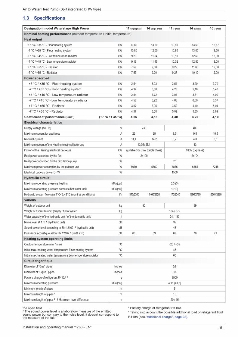
1 Sound pressure level in (x)m of the device, 1,5m of the ground, the open field. 2 The sound power level is a laboratory measure of the emitted sound power but contrary to the noise level, it doesn't correspond to the measure of the felt.
3 Refrigerant R410A (as per the standard EN 378.1). 4 Factory charge of refrigerant R410A.5 Taking into account the possible additional load of refrigerant fluid R410A (see "Additional charge", page 22).
Installation and operating manual "1768 - EN" - 5 -
Air to Water Heat Pump (Split integrated DHW type)
Designation model Waterstage High Power 11 Single phase 14 Single phase 11 3-phase 14 3-phase 16 3-phase
Nominal heating performances (outdoor temperature / initial temperature)
Heat output +7 °C / +35 °C - Floor heating system kW 10,80 13,50 10,80 13,50 15,17 -7 °C / +35 °C - Floor heating system kW 10,80 12,00 10,80 13,00 13,50 +7 °C / +45 °C - Low temperature radiator kW 9,23 11,54 10,10 12,60 13,00 -7 °C / +45 °C - Low temperature radiator kW 9,16 11,45 10,02 12,50 13,00 +7 °C / +55 °C - Radiator kW 7,59 9,68 9,29 11,60 12,00 -7 °C / +55 °C - Radiator kW 7,57 9,20 9,27 10,10 12,00Power absorbed +7 °C / +35 °C - Floor heating system kW 2,54 3,23 2,51 3,20 3,70 -7 °C / +35 °C - Floor heating system kW 4,32 5,08 4,28 5,18 5,40 +7 °C / +45 °C - Low temperature radiator kW 2,84 3,72 3,01 3,81 4,00 -7 °C / +45 °C - Low temperature radiator kW 4,58 5,92 4,63 6,00 6,37 +7 °C / +55 °C - Radiator kW 3,07 3,95 3,52 4,40 5,04 -7 °C / +55 °C - Radiator kW 4,57 5,08 5,09 5,65 6,89Coefficient of performance (COP) (+7 °C / + 35 °C) 4,25 4,18 4,30 4,22 4,10Electrical characteristicsSupply voltage (50 HZ) V 230 400Maximum current for appliance A 22 25 8,5 9,5 10,5Nominal current A 11,4 14,2 3,7 4,8 5,5Maximum current of the Heating electrical back-ups A 13,05 / 26,1 13Power of the Heating electrical back-ups kW ajustable 3 or 6 kW (Single phase) 9 kW (3-phase)Real power absorbed by the fan W 2x100 2x10⁴Real power absorbed by the circulation pump W 70Maximum power absorption by the outdoor unit W 5060 5750 5865 6555 7245Electrical back-up power DHW W 1500Hydraulic circuitMaximum operating pressure heating MPa (bar) 0,3 (3)Maximum operating pressure domestic hot water tank MPa (bar) 1 (10)Hydraulic system flow rate 4°C<Δt<8°C (nominal conditions) l/h 1170/2340 1460/2920 1170/2340 1390/2790 1650 / 3290VariousWeight of outdoor unit kg 92 99Weight of hydraulic unit (empty / full of water) kg 154 / 372Water capacity of the hydraulic unit / of the domestic tank l 24 / 190Noise level at 1 m 1 (hydraulic unit) dB 39Sound power level according to EN 12102 2 (hydraulic unit) dB 46Puissance acoustique selon EN 12102 2 (unité ext.) dB 68 69 69 70 71Heating system operating limitsOutdoor temperature mini / maxi °C -25 / +35Initial max. heating water temperature Floor heating system °C 45Initial max. heating water temperature Low temperature radiator °C 60Circuit frigorifiqueDiameter of "Gas" pipes inches 5/8Diameter of "Liquid" pipes inches 3/8Factory charge of refrigerant R410A 3 g 2500Maximum operating pressure MPa (bar) 4,15 (41,5)Minimum length of pipes m 5Maximum length of pipes 4 m 15Maximum length of pipes 5 / Maximum level difference m 20 / 15
31 77900330 12
9400
650
21
1290
151
170
196
370
99
3/8
5/8
Air
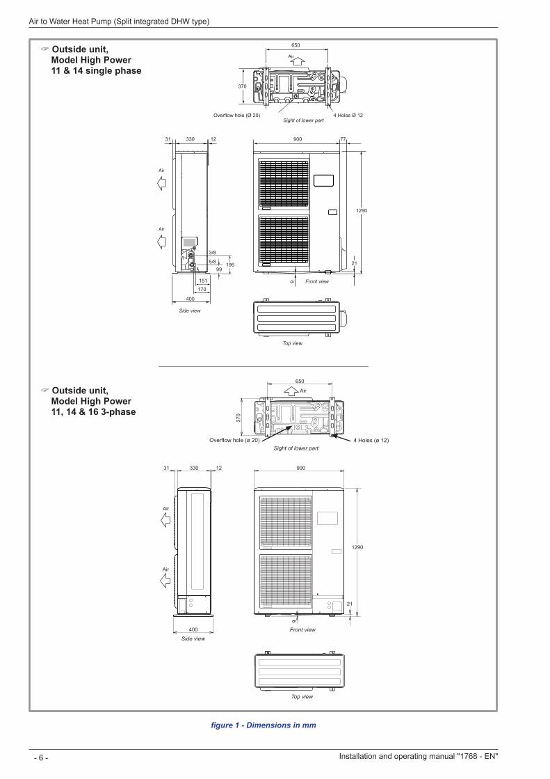
Overflow hole (Ø 20) 4 Ø 12Holes
Top view
Front view
Sight of lower part
Side view
Air
Air
900
1290
9
21
650
370
Air
31 12330
400
Air
Air
figure 1 - Dimensions in mm
Overflow hole (ø 20) 4 Holes (ø 12)Sight of lower part
Front view
Top view
Side view
Installation and operating manual "1768 - EN"
Air to Water Heat Pump (Split integrated DHW type)
- 6 -
" Outside unit, Model High Power 11, 14 & 16 3-phase
" Outside unit, Model High Power 11 & 14 single phase
175 210
1840
47
244
1189
1141
648
1296
698 103
1850
43
630599576
644
272 55
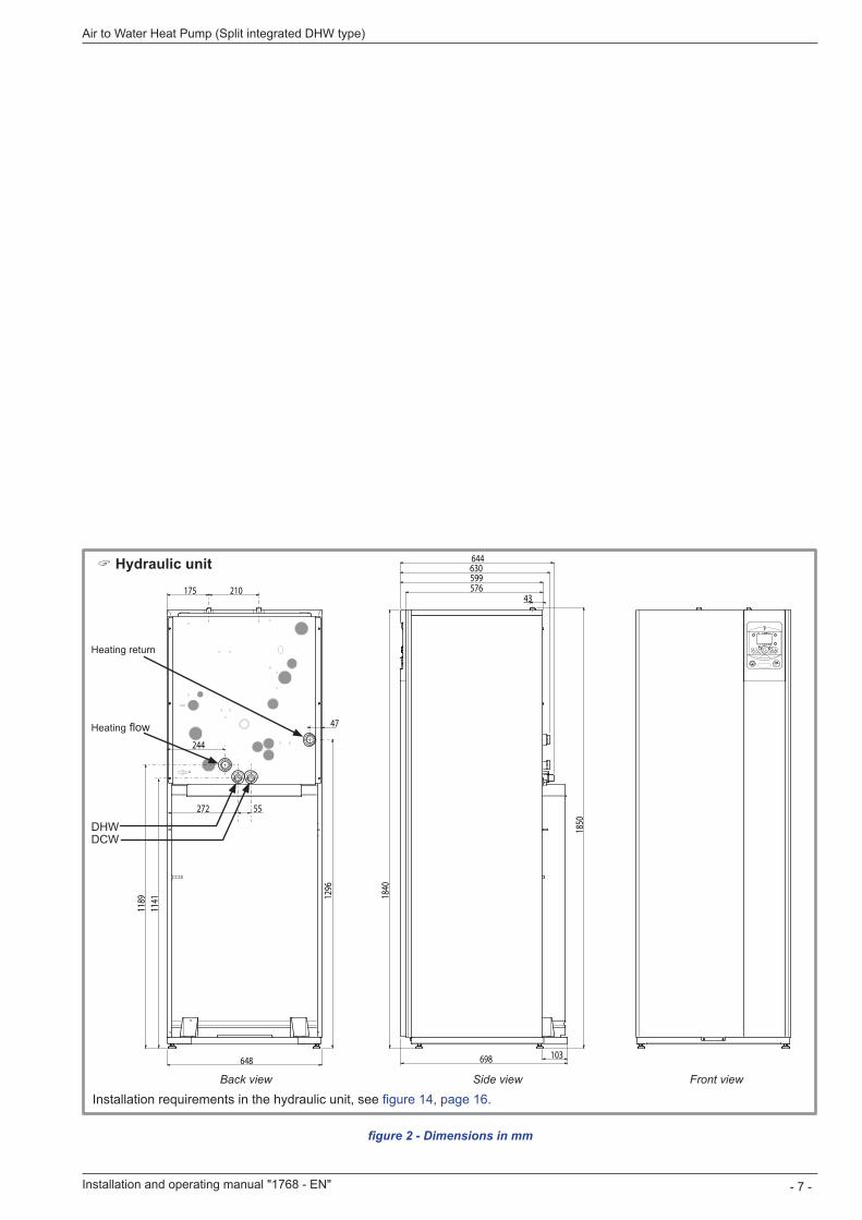
figure 2 - Dimensions in mm
Installation requirements in the hydraulic unit, see figure 14, page 16.Back view
Heating flow
DHWDCW
Heating return
Side view Front view
" Hydraulic unit
Installation and operating manual "1768 - EN" - 7 -
Air to Water Heat Pump (Split integrated DHW type)
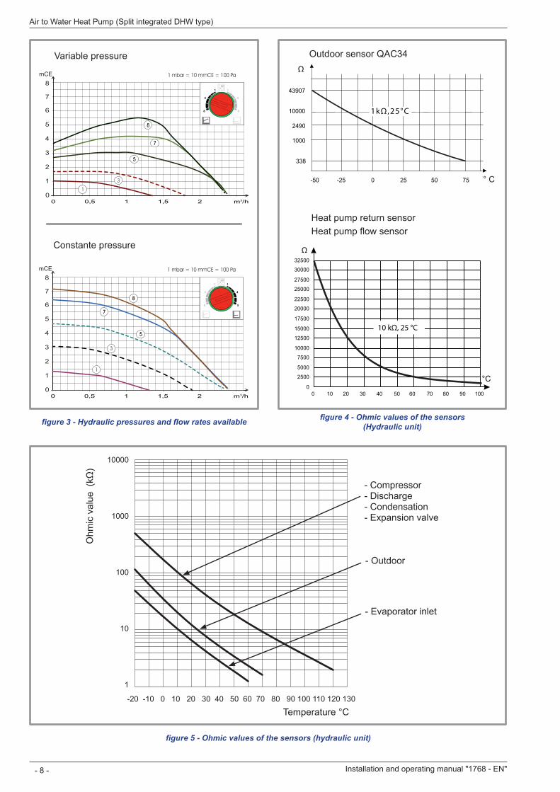
figure 3 - Hydraulic pressures and flow rates available
-50
1000
10000
43907
2490
338
-25 0 25 50 75 ° C
0
2500
5000
7500
10000
12500
15000
17500
20000
22500
25000
27500
30000
32500
0 10 20 30 40 50 60 70 80 90 100
°C
Outdoor sensor QAC34
Heat pump return sensorHeat pump flow sensor
figure 4 - Ohmic values of the sensors (Hydraulic unit)
figure 5 - Ohmic values of the sensors (hydraulic unit)
-20 -10 0 10 20 30 40 50 60 70 80 90 100 110 120 130
10000
1000
100
10
1
- Compressor - Discharge - Condensation - Expansion valve
- Evaporator inlet
- Outdoor
Temperature °C
Ohm
ic v
alue
(kΩ
)
0
1
2
3
4
5
6
7
8mCE 1 mbar = 10 mmCE = 100 Pa
m /h31 1,5 20,500 0,5 1 1,5 2 m3/h
1
3
55
77
88
0
1
2
3
4
5
6
7
8mCE 1 mbar = 10 mmCE = 100 Pa
m /h31 1,5 20,500 0,5 1 1,5 2 m3/h
1
3
55
77
88
Variable pressure
Constante pressure
Installation and operating manual "1768 - EN"
Air to Water Heat Pump (Split integrated DHW type)
- 8 -
1 .4 Description
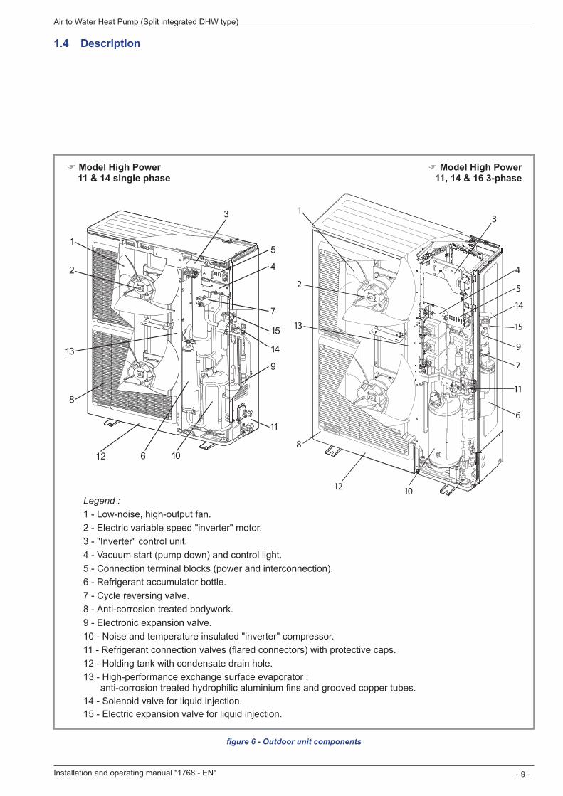
figure 6 - Outdoor unit components
Legend :1 - Low-noise, high-output fan.2 - Electric variable speed "inverter" motor.3 - "Inverter" control unit.4 - Vacuum start (pump down) and control light.5 - Connection terminal blocks (power and interconnection).6 - Refrigerant accumulator bottle.7 - Cycle reversing valve.8 - Anti-corrosion treated bodywork.9 - Electronic expansion valve.10 - Noise and temperature insulated "inverter" compressor.11 - Refrigerant connection valves (flared connectors) with protective caps.12 - Holding tank with condensate drain hole.13 - High-performance exchange surface evaporator ;
anti-corrosion treated hydrophilic aluminium fins and grooved copper tubes.14 - Solenoid valve for liquid injection.15 - Electric expansion valve for liquid injection.
1
2
3
4
5
6
7
8
9
10
11
12
13 14
15
WO*K1**LCT
2
13
4
5
7
9
8
1012
13
11
14
15
6
Installation and operating manual "1768 - EN" - 9 -
Air to Water Heat Pump (Split integrated DHW type)
" Model High Power 11 & 14 single phase
" Model High Power 11, 14 & 16 3-phase
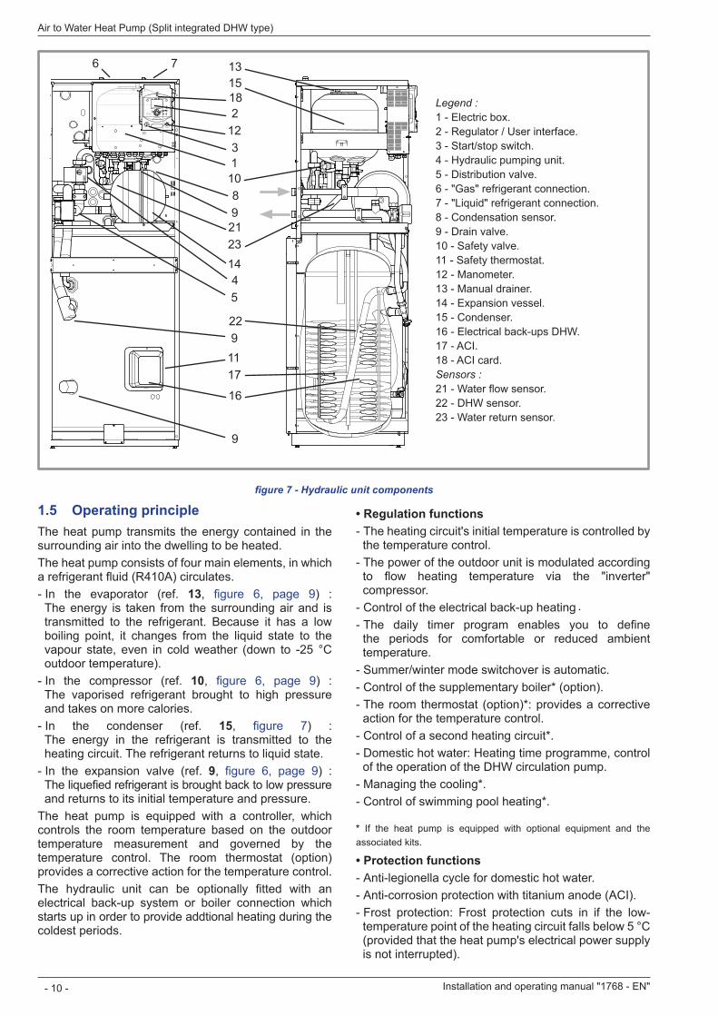
1 .5 Operating principleThe heat pump transmits the energy contained in the surrounding air into the dwelling to be heated.The heat pump consists of four main elements, in which a refrigerant fluid (R410A) circulates. - In the evaporator (ref. 13, figure 6, page 9) : The energy is taken from the surrounding air and is transmitted to the refrigerant. Because it has a low boiling point, it changes from the liquid state to the vapour state, even in cold weather (down to -25 °C outdoor temperature). - In the compressor (ref. 10, figure 6, page 9) : The vaporised refrigerant brought to high pressure and takes on more calories. - In the condenser (ref. 15, figure 7) : The energy in the refrigerant is transmitted to the heating circuit. The refrigerant returns to liquid state. - In the expansion valve (ref. 9, figure 6, page 9) : The liquefied refrigerant is brought back to low pressure and returns to its initial temperature and pressure.
The heat pump is equipped with a controller, which controls the room temperature based on the outdoor temperature measurement and governed by the temperature control. The room thermostat (option) provides a corrective action for the temperature control.The hydraulic unit can be optionally fitted with an electrical back-up system or boiler connection which starts up in order to provide addtional heating during the coldest periods.
Legend :1 - Electric box.2 - Regulator / User interface.3 - Start/stop switch.4 - Hydraulic pumping unit.5 - Distribution valve.6 - "Gas" refrigerant connection.7 - "Liquid" refrigerant connection.8 - Condensation sensor.9 - Drain valve.10 - Safety valve.11 - Safety thermostat.12 - Manometer.13 - Manual drainer.14 - Expansion vessel.15 - Condenser.16 - Electrical back-ups DHW.17 - ACI.18 - ACI card.Sensors :21 - Water flow sensor.22 - DHW sensor.23 - Water return sensor.
• Regulation functions - The heating circuit's initial temperature is controlled by the temperature control. - The power of the outdoor unit is modulated according to flow heating temperature via the "inverter" compressor. - Control of the electrical back-up heating (option). - The daily timer program enables you to define the periods for comfortable or reduced ambient temperature. - Summer/winter mode switchover is automatic. - Control of the supplementary boiler* (option). - The room thermostat (option)*: provides a corrective action for the temperature control. - Control of a second heating circuit*. - Domestic hot water: Heating time programme, control of the operation of the DHW circulation pump. - Managing the cooling*. - Control of swimming pool heating*.
* If the heat pump is equipped with optional equipment and the associated kits.
• Protection functions - Anti-legionella cycle for domestic hot water. - Anti-corrosion protection with titanium anode (ACI). - Frost protection: Frost protection cuts in if the low-temperature point of the heating circuit falls below 5 °C (provided that the heat pump's electrical power supply is not interrupted).
figure 7 - Hydraulic unit components
312
110
4
98
212314
5
17
22
16
11
9
9
21815136 7
Installation and operating manual "1768 - EN"
Air to Water Heat Pump (Split integrated DHW type)
- 10 -
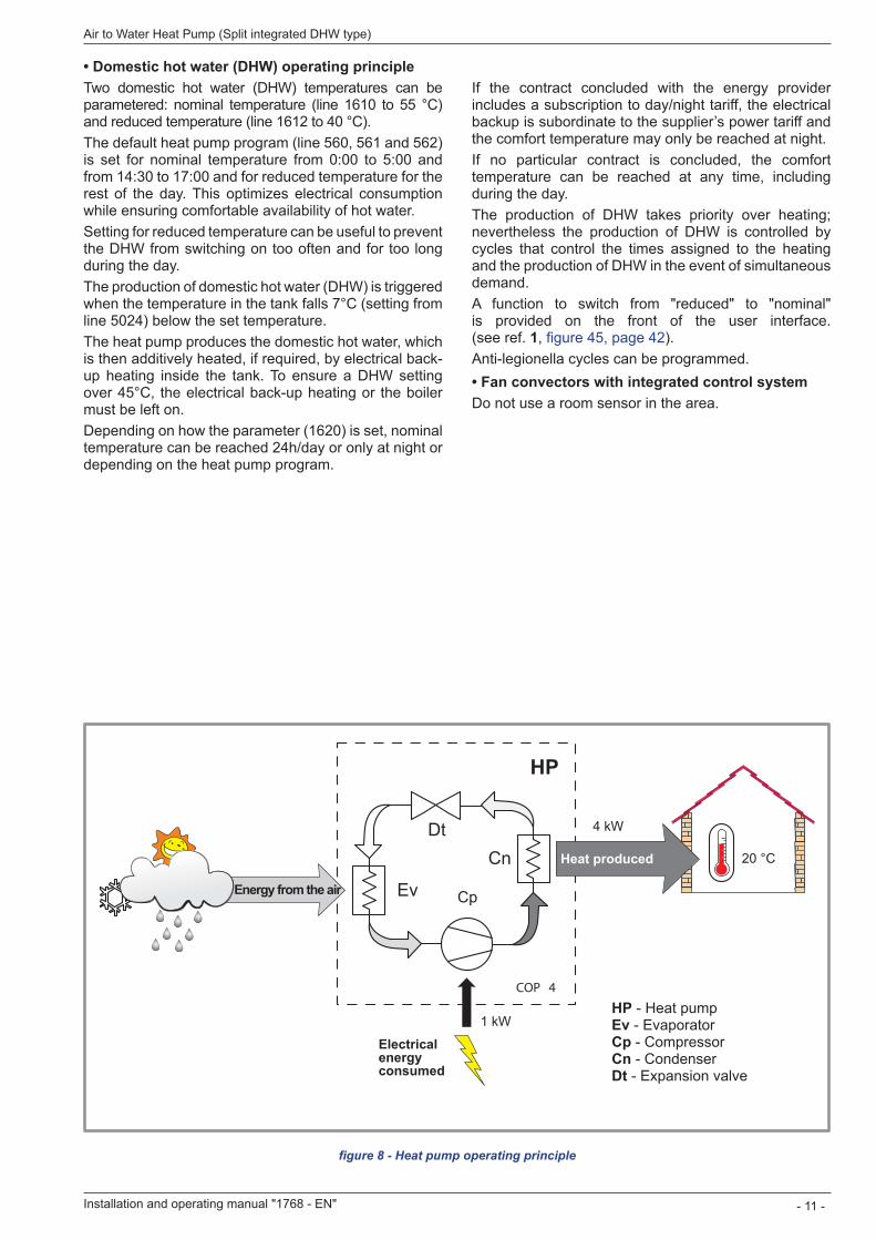
• Domestic hot water (DHW) operating principleTwo domestic hot water (DHW) temperatures can be parametered: nominal temperature (line 1610 to 55 °C) and reduced temperature (line 1612 to 40 °C).The default heat pump program (line 560, 561 and 562) is set for nominal temperature from 0:00 to 5:00 and from 14:30 to 17:00 and for reduced temperature for the rest of the day. This optimizes electrical consumption while ensuring comfortable availability of hot water.Setting for reduced temperature can be useful to prevent the DHW from switching on too often and for too long during the day.The production of domestic hot water (DHW) is triggered when the temperature in the tank falls 7°C (setting from line 5024) below the set temperature.The heat pump produces the domestic hot water, which is then additively heated, if required, by electrical back-up heating inside the tank. To ensure a DHW setting over 45°C, the electrical back-up heating or the boiler must be left on.Depending on how the parameter (1620) is set, nominal temperature can be reached 24h/day or only at night or depending on the heat pump program.
figure 8 - Heat pump operating principle
If the contract concluded with the energy provider includes a subscription to day/night tariff, the electrical backup is subordinate to the supplier’s power tariff and the comfort temperature may only be reached at night.If no particular contract is concluded, the comfort temperature can be reached at any time, including during the day.The production of DHW takes priority over heating; nevertheless the production of DHW is controlled by cycles that control the times assigned to the heating and the production of DHW in the event of simultaneous demand.A function to switch from "reduced" to "nominal" is provided on the front of the user interface. (see ref. 1, figure 45, page 42).Anti-legionella cycles can be programmed.• Fan convectors with integrated control systemDo not use a room sensor in the area.
Ev
DtCn
Cp
1 kW
COP 4
4 kW
20 °C
PAC
HP - Heat pumpEv - EvaporatorCp - CompressorCn - CondenserDt - Expansion valve
Energy from the air
Heat produced
Electrical energy consumed
HP
Installation and operating manual "1768 - EN" - 11 -
Air to Water Heat Pump (Split integrated DHW type)
2 .1 Regulation installation and maintenance conditionsThe appliance must be installed and the maintained by an approved professional in accordance with the prevailing regulations and code of practice, in particular: - The legislation on the handling of refrigerants. - Heating installation with floor heating system. - Low voltage electrical installations - Rules.
2 .2 Unpacking and reservations
2 .2 .1 Receipt Carefully check, in the carrier's presence, the general appearance of the appliances and check that the outdoor unit is not laid on its side or back.In the case of any dispute, state any appropriate reservations to the carrier in writing within 48 hours and send a copy of this letter to the After-Sales service.
2 .2 .2 HandlingThe outdoor unit should not be laid on its side or back during transport. If not kept upright during transport, the appliance could be damaged through displacement of the refrigerant and deformation of the compressor suspension. Any damage caused by transportation of the unit lying down is not covered by the warranty.If necessary the outdoor unit may be tilted only during manual handling (to go through a door or use a staircase). This operation must be conducted very carefully and the appliance must be immediately restored to upright position.
2 .2 .3 Containment of refrigerant circuitsAll refrigerant circuits fear contamination from dust and moisture. If such pollutants introduced into refrigerant circuit, they can contribute to degrade the reliability of the heat pump.
" It’s necessary to ensure correct containment connections and refrigerant circuits (hydraulic unit, outdoor unit). " In case of subsequent failure and expertise, the finding of the presence of moisture or foreign objects into the compressor oil would lead to systematic exclusion of warranty.
- Check upon receipt that the fittings and the refrigerant circuit caps mounted on hydraulic unit and outdoor unit are properly seated and locked (impossible to loosen bare hands). If not the case, tighten them using an against wrench. - Check also that the refrigerant connections are sealed (plastic caps or tubes crushed at the ends and soldered). If the caps must be removed during installation (tubes cut by example), put back them as soon as possible.
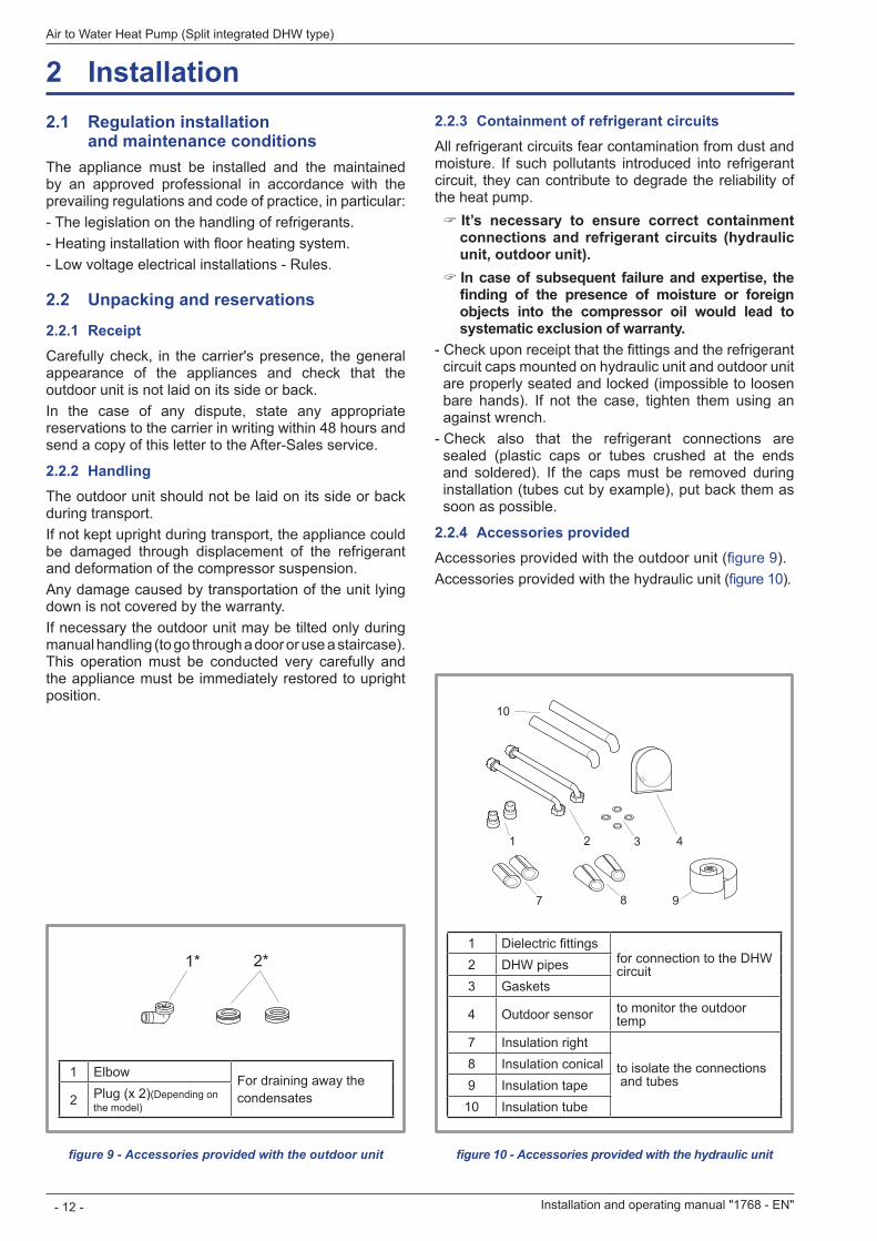
2 .2 .4 Accessories providedAccessories provided with the outdoor unit (figure 9).Accessories provided with the hydraulic unit (figure 10).
figure 9 - Accessories provided with the outdoor unit figure 10 - Accessories provided with the hydraulic unit
1* 3**2* 4
1 Elbow For draining away thecondensates2 Plug (x 2)(Depending on
the model)
1 Dielectric fittingsfor connection to the DHW circuit2 DHW pipes
3 Gaskets
4 Outdoor sensor to monitor the outdoor temp
7 Insulation right
to isolate the connections and tubes
8 Insulation conical9 Insulation tape
10 Insulation tube
64
10
9
5
32
8
1
7
2 Installation
Installation and operating manual "1768 - EN"
Air to Water Heat Pump (Split integrated DHW type)
- 12 -
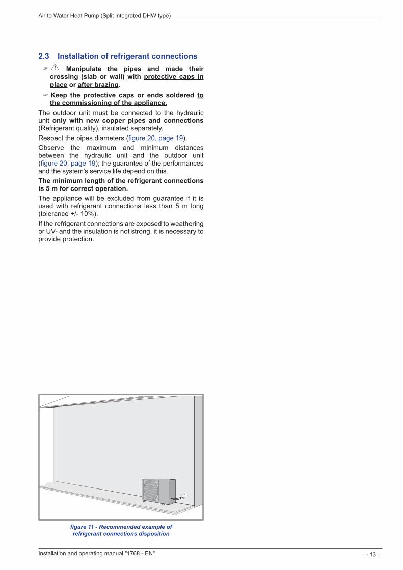
2 .3 Installation of refrigerant connections " Manipulate the pipes and made their crossing (slab or wall) with protective caps in place or after brazing . " Keep the protective caps or ends soldered to the commissioning of the appliance .
The outdoor unit must be connected to the hydraulic unit only with new copper pipes and connections (Refrigerant quality), insulated separately.Respect the pipes diameters (figure 20, page 19).Observe the maximum and minimum distances between the hydraulic unit and the outdoor unit (figure 20, page 19); the guarantee of the performances and the system's service life depend on this.The minimum length of the refrigerant connections is 5 m for correct operation .The appliance will be excluded from guarantee if it is used with refrigerant connections less than 5 m long (tolerance +/- 10%).If the refrigerant connections are exposed to weathering or UV- and the insulation is not strong, it is necessary to provide protection.
figure 11 - Recommended example of refrigerant connections disposition
Installation and operating manual "1768 - EN" - 13 -
Air to Water Heat Pump (Split integrated DHW type)
2 .4 Installation of the outdoor unit
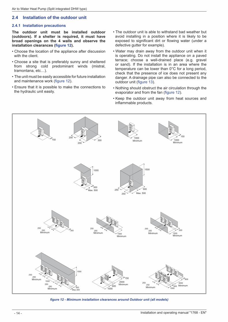
2 .4 .1 Installation precautionsThe outdoor unit must be installed outdoor (outdoors). If a shelter is required, it must have broad openings on the 4 walls and observe the installation clearances (figure 12).• Choose the location of the appliance after discussion
with the client.• Choose a site that is preferably sunny and sheltered
from strong cold predominant winds (mistral, tramontana, etc…).
• The unit must be easily accessible for future installation and maintenance work (figure 12).
• Ensure that it is possible to make the connections to the hydraulic unit easily.
• The outdoor unit is able to withstand bad weather but avoid installing in a position where it is likely to be exposed to significant dirt or flowing water (under a defective gutter for example).
• Water may drain away from the outdoor unit when it is operating. Do not install the appliance on a paved terrace; choose a well-drained place (e.g. gravel or sand). If the installation is in an area where the temperature can be lower than 0°C for a long period, check that the presence of ice does not present any danger. A drainage pipe can also be connected to the outdoor unit (figure 13).
• Nothing should obstruct the air circulation through the evaporator and from the fan (figure 12).
• Keep the outdoor unit away from heat sources and inflammable products.
figure 12 - Minimum installation clearances around Outdoor unit (all models)
1000
150
600
2000 or more 250
or more
250 3000 or more
600
6001500
250 or more
250
250 250 or more
1500
500Max.300
1500
300Max. 500
1000 1500
250
250
500
Max. 500
1000 or more
200300
2001000 or more
150150
250250 or more 1500
or more
250250 or more
300250
250 or more 1500
or more
500
MinimumMinimum
MinimumMinimum
MinimumMinimum
Minimum
MinimumMinimumMinimum
Minimum
Minimum
Installation and operating manual "1768 - EN"
Air to Water Heat Pump (Split integrated DHW type)
- 14 -
• Make sure the appliance not disturb the surrounding area or users (noise level, draught generated, low temperature of the air being blown out, with the risk of freezing plants in its path).
• The surface on which the appliance is installed must: - be permeable (soil, gravel, etc), - support its weight easily, - provide a solid fixing and - not transmit any vibration to the dwelling. (Anti-vibratory blocks are available as an option).
• The wall bracket can not be used in conditions likely to transmit vibrations, ground position is preferred.
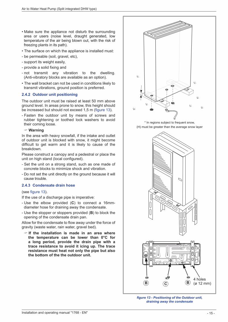
2 .4 .2 Outdoor unit positioningThe outdoor unit must be raised at least 50 mm above ground level. In areas prone to snow, this height should be increased but should not exceed 1,5 m (figure 13). - Fasten the outdoor unit by means of screws and rubber tightening or toothed lock washers to avoid their coming loose.
" WarningIn the area with heavy snowfall, if the intake and outlet of outdoor unit is blocked with snow, it might become difficult to get warm and it is likely to cause of the breakdown.Please construct a canopy and a pedestral or place the unit on high stand (local configured). - Set the unit on a strong stand, such as one made of concrete blocks to minimize shock and vibration. - Do not set the unit directly on the ground because it will cause trouble.
2 .4 .3 Condensate drain hose(see figure 13).If the use of a discharge pipe is imperative: - Use the elbow provided (C) to connect a 16mm-diameter hose for draining away the condensate. - Use the stopper or stoppers provided (B) to block the opening of the condensate drain pan.
Allow for the condensate to flow away under the force of gravity (waste water, rain water, gravel bed).
" If the installation is made in an area where the temperature can be lower than 0°C for a long period, provide the drain pipe with a trace resistance to avoid it icing up . The trace resistance must heat not only the pipe but also the bottom of the the outdoor unit .
figure 13 - Positioning of the Outdoor unit, draining away the condensate
* In regions subject to frequent snow, (H) must be greater than the average snow layer
BB C4 holes(ø 12 mm)
Installation and operating manual "1768 - EN" - 15 -
Air to Water Heat Pump (Split integrated DHW type)
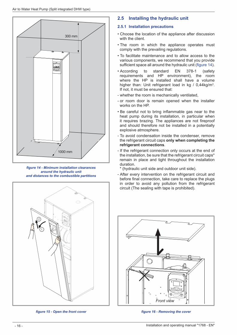
figure 14 - Minimum installation clearances around the hydraulic unit
and distances to the combustible partitions
300 mm
1000 mm
125 mm
1800
mm
Front view
2 .5 Installing the hydraulic unit
2 .5 .1 Installation precautions
• Choose the location of the appliance after discussion with the client.
• The room in which the appliance operates must comply with the prevailing regulations.
• To facilitate maintenance and to allow access to the various components, we recommend that you provide sufficient space all around the hydraulic unit (figure 14).
• According to standard EN 378-1 (safety requirements and HP environment), the room where the HP is installed shall have a volume higher than: Unit refrigerant load in kg / 0,44kg/m3 If not, it must be ensured that: - whether the room is mechanically ventilated, - or room door is remain opened when the installer works on the HP.
• Be careful not to bring inflammable gas near to the heat pump during its installation, in particular when it requires brazing. The appliances are not fireproof and should therefore not be installed in a potentially explosive atmosphere. - To avoid condensation inside the condenser, remove the refrigerant circuit caps only when completing the refrigerant connections - If the refrigerant connection only occurs at the end of the installation, be sure that the refrigerant circuit caps* remain in place and tight throughout the installation duration.* (hydraulic unit side and outdoor unit side). - After every intervention on the refrigerant circuit and before final connection, take care to replace the plugs in order to avoid any pollution from the refrigerant circuit (The sealing with tape is prohibited).
1
2
figure 15 - Open the front cover figure 16 - Removing the cover
Installation and operating manual "1768 - EN"
Air to Water Heat Pump (Split integrated DHW type)
- 16 -
" This appliance uses refrigerant R410A .Comply with the legislation for handling refrigerants.
3 .1 Rules and precautions " Connections must be made the day of the filling the installation with gas (3 .4, page 20).
• Minimum necessary tools - Set of manometers (Manifold) with hoses exclusively reserved for HFCs (Hydrofluorocarbons). - Vacuum gauge whith isolation valves. - Vacuum pump specially for HFCs (use of a traditional vacuum pump is authorized if, and only if, it is fitted with a non-return valve on the suction side). - Flaring tool, Pipe-cutter, Deburring tool, Wrenches. - Refrigerant gas leak detector certified (sensitivity 5g/year).
" Provision on using tools that have been in contact with HCFCs (R22 for example) or CFCs. " The manufacturer declines any liability with regard to the guarantee if the above instructions are not observed .
• Flared connections " Lubrication with mineral oil (for R12, R22) is forbidden .
- Only lubricate with polyolester refrigerant oil (POE). If POE is not available, fit without lubrication.
Coat the flared surface with POE refrigerant oil .Do not use mineral oil .
• Brazing on the refrigerant circuit (if necessary) - Silver brazing (40% minimum recommended). - Brazing only under dry nitrogen internal flux.
• Remarks - After every intervention on the refrigerant circuit and before final connection, take care to replace the plugs in order to avoid any pollution from the refrigerant circuit. - To eliminate any filings in the pipes, use dry nitrogen to avoid introducing any humidity that may adversely affect the appliances operation. In general, take every precaution to avoid humidity penetrating into the appliance. - Proceed to insulate the "Gas" and "Liquid" pipes to avoid any condensation. Use pipe insulators resistant to temperatures over 90°C. In addition if the humidity level in areas where the refrigerant pipes are installed is expected to exceed 70%, protect the pipes with pipe insulators. Use an insulating material thicker than 15mm if the humidity level is 70~80%, and an insulating material thicker than 20mm if the humidity exceeds 80%. If the recommended thicknesses are
not observed under the conditions described above, condensation will form on the surface of the insulation material. Lastly, take care to use pipe insulators whose thermal conductivity is 0.045 W/mK or less when the temperature is 20°C. The insulation must be impermeable to resist the passage of steam during the defrosting cycles (fibreglass wool is prohibited).
3 .2 Shaping the refrigerant pipes
3 .2 .1 BendingThe refrigerant pipes must be shaped only on a bending machine or with a bending spring in order to avoid any risk of crushing or breaking them.
" Warning !• Remove the insulation material locally to bend the
pipes. • Do not bend the copper to any angle over 90°.Never bend pipes more than 3 times in the same position otherwise traces of fracturing may appear (from strain-hardening the metal).
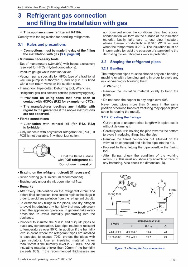
3 .2 .2 Creating the flarings - Cut the pipe to an appropriate length with a pipe-cutter without deforming it. - Carefully deburr it, holding the pipe towards the bottom to avoid introducing filings into the pipe. - Remove the flared connection nut situated on the valve to be connected and slip the pipe into the nut. - Proceed to flare, letting the pipe overflow the flaring tool. - After flaring, check the condition of the working radius (L). This must not show any scratch or trace of any fracturing. Also check the dimension (B).
3 Refrigerant gas connection and filling the installation with gas
figure 17 - Flaring for flare connections
Flaring tool
Hose
Flarenut
B
L
C
ø Hosedimensions in mm
L B 0/-0,4 C
9,52 (3/8") 2,5 to 2,7 13,2 22
15,88 (5/8") 2,9 to 3,1 19,7 29
Installation and operating manual "1768 - EN" - 17 -
Air to Water Heat Pump (Split integrated DHW type)
3 .3 Check and connecting
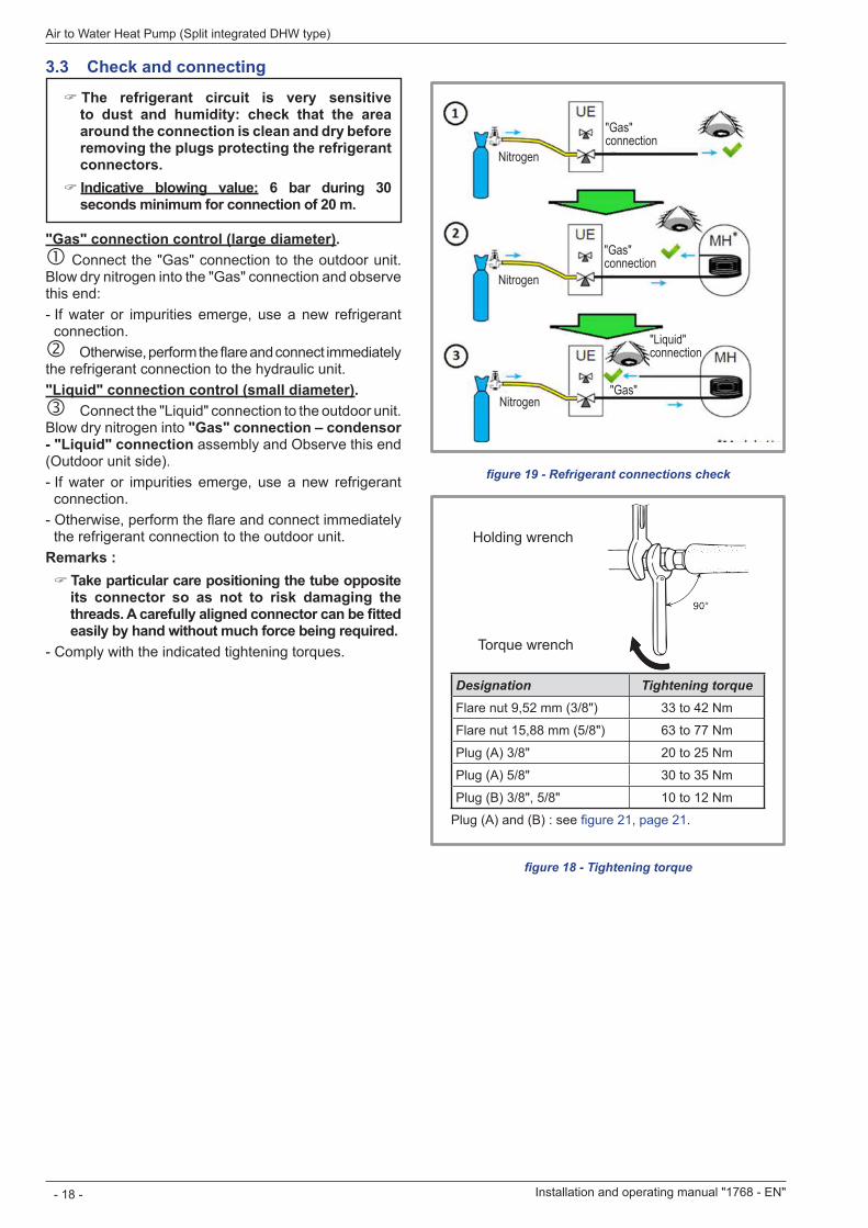
" The refrigerant circuit is very sensitive to dust and humidity: check that the area around the connection is clean and dry before removing the plugs protecting the refrigerant connectors . " Indicative blowing value: 6 bar during 30 seconds minimum for connection of 20 m .
"Gas" connection control (large diameter) . Connect the "Gas" connection to the outdoor unit. Blow dry nitrogen into the "Gas" connection and observe this end: - If water or impurities emerge, use a new refrigerant connection. Otherwise, perform the flare and connect immediately the refrigerant connection to the hydraulic unit."Liquid" connection control (small diameter) . Connect the "Liquid" connection to the outdoor unit.Blow dry nitrogen into "Gas" connection – condensor - "Liquid" connection assembly and Observe this end (Outdoor unit side). - If water or impurities emerge, use a new refrigerant connection. - Otherwise, perform the flare and connect immediately the refrigerant connection to the outdoor unit.
Remarks : " Take particular care positioning the tube opposite its connector so as not to risk damaging the threads. A carefully aligned connector can be fitted easily by hand without much force being required.
- Comply with the indicated tightening torques.
Designation Tightening torqueFlare nut 9,52 mm (3/8") 33 to 42 Nm
Flare nut 15,88 mm (5/8") 63 to 77 Nm
Plug (A) 3/8" 20 to 25 Nm
Plug (A) 5/8" 30 to 35 Nm
Plug (B) 3/8", 5/8" 10 to 12 Nm
Plug (A) and (B) : see figure 21, page 21
Holding wrench
Torque wrench
figure 18 - Tightening torque
figure 19 - Refrigerant connections check
Nitrogen
Nitrogen
Nitrogen
"Gas" connection
"Gas" connection
"Gas"
"Liquid" connection
Installation and operating manual "1768 - EN"
Air to Water Heat Pump (Split integrated DHW type)
- 18 -
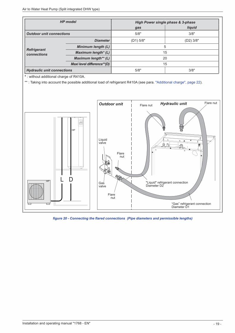
figure 20 - Connecting the flared connections (Pipe diameters and permissible lengths)
HP model alféa excellia duo Single phase & 3-phasegas liquid
Outdoor unit connections 5/8" 3/8"
Refrigerant connections
Diameter (D1) 5/8" (D2) 3/8"
Minimum length (L) 5Maximum length* (L) 15
Maximum length** (L) 20Maxi level difference**(D) 15
Hydraulic unit connections 5/8" 3/8"
* : without additional charge of R410A.** : Taking into account the possible additional load of refrigerant R410A (see para. "Additional charge", page 22).
DL
HP
HP
“Gas” refrigerant connection Diameter D1
"Liquid" refrigerant connection Diameter D2
Flare nutFlare nut
Flare nut
Flare nut
Liquid valve
Gas valve
Hydraulic unitOutdoor unit
Installation and operating manual "1768 - EN" - 19 -
Air to Water Heat Pump (Split integrated DHW type)
High Power single phase & 3-phase
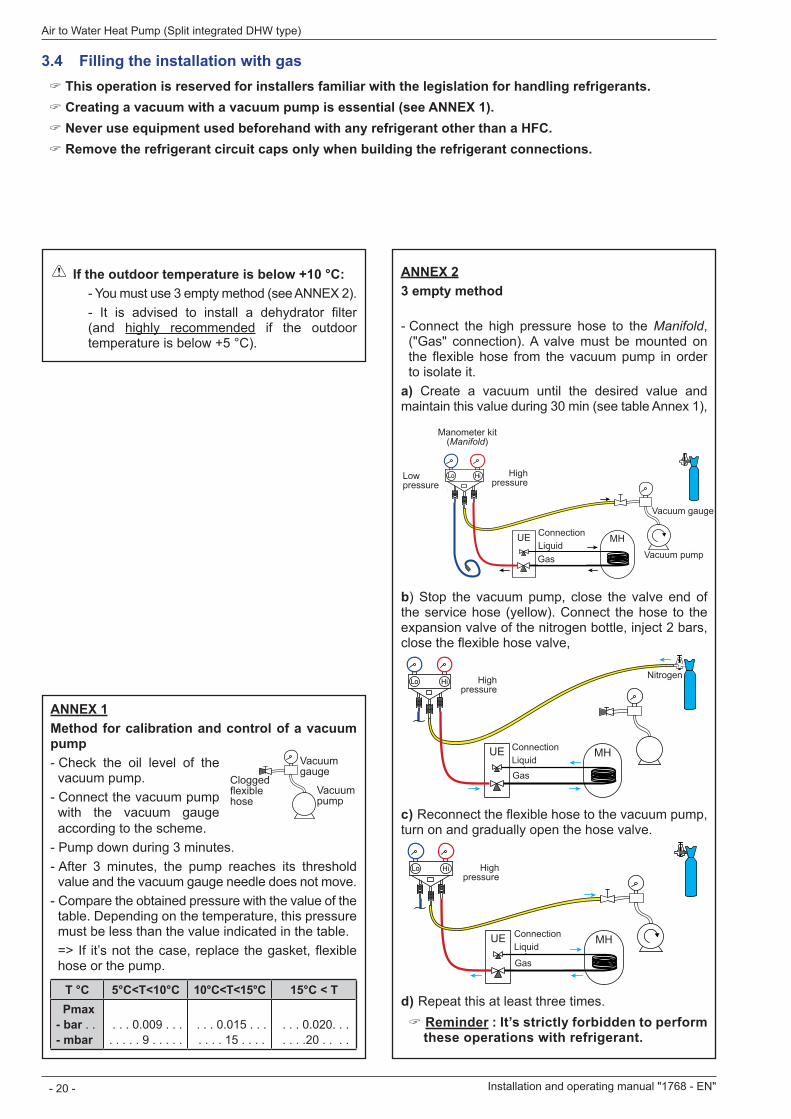
3 .4 Filling the installation with gas " This operation is reserved for installers familiar with the legislation for handling refrigerants. " Creating a vacuum with a vacuum pump is essential (see ANNEX 1). " Never use equipment used beforehand with any refrigerant other than a HFC. " Remove the refrigerant circuit caps only when building the refrigerant connections.
ANNEX 23 empty method
- Connect the high pressure hose to the Manifold, ("Gas" connection). A valve must be mounted on the flexible hose from the vacuum pump in order to isolate it.
a) Create a vacuum until the desired value and maintain this value during 30 min (see table Annex 1),
Lo Hi
UE MHLiaison...liquidegaz
Hautepression
Jeu de manomètres(Manifold)
Basse pression
Vacuomètre
Pompe à vide
Manometer kit (Manifold)
Low pressure
High pressure
Vacuum pump
ConnectionLiquidGas
Vacuum gauge
b) Stop the vacuum pump, close the valve end of the service hose (yellow). Connect the hose to the expansion valve of the nitrogen bottle, inject 2 bars, close the flexible hose valve,
Lo Hi
UE MHLiaison...liquidegaz
Hautepression
AzoteHigh pressure
Nitrogen
ConnectionLiquidGas
c) Reconnect the flexible hose to the vacuum pump, turn on and gradually open the hose valve.
Lo Hi
UE MHLiaison...liquidegaz
Hautepression
High pressure
ConnectionLiquid
Gas
d) Repeat this at least three times. " Reminder : It’s strictly forbidden to perform these operations with refrigerant.
ANNEX 1Method for calibration and control of a vacuum pump - Check the oil level of the vacuum pump. - Connect the vacuum pump with the vacuum gauge according to the scheme. - Pump down during 3 minutes. - After 3 minutes, the pump reaches its threshold value and the vacuum gauge needle does not move. - Compare the obtained pressure with the value of the table. Depending on the temperature, this pressure must be less than the value indicated in the table.=> If it’s not the case, replace the gasket, flexible hose or the pump.
T °C 5°C<T<10°C 10°C<T<15°C 15°C < T Pmax - bar - mbar
0 009 9
0 015 15
0 020 20
VacuomètreFlexible bouché
Pompeà vide
Clogged flexible hose
Vacuum pump
Vacuum gauge
If the outdoor temperature is below +10 °C:- You must use 3 empty method (see ANNEX 2).- It is advised to install a dehydrator filter (and highly recommended if the outdoor temperature is below +5 °C).
Installation and operating manual "1768 - EN"
Air to Water Heat Pump (Split integrated DHW type)
- 20 -
3 .4 .1 Seal test - Remove the protective plugs (B) from the charging hole (Schrader) in the "Gas" valve (large diameter). - Connect the high pressure hose to the Manifold - Connect the bottle of nitrogen to the Manifold (Use only dry nitrogen type U). - Pressurize the refrigerant circuit with nitrogen (10 bar maximum) ("Gas" connection – condensor - "Liquid" connection assembly). - Let the circuit under pressure for 30 minutes.
Lo Hi
UE MHLiaison...liquidegaz
Hautepression
Azote10 bars max.30 mn mini
High pressure
NitrogenMax. 10 bar
during 30 mn mini.
ConnectionLiquid
Gas
- If pressure drop, get it down to 1 bar and look for leaks with a leak detector, repair and repeat the test.
Lo Hi
UE MHLiaison...liquidegaz
Hautepression
Contrôle d’étanchéité
Vanne fermée,Contrôle pression
High pressure
Closed valve,pressure control
Leak control
- When the pressure is stable and leakage is excluded, drain nitrogen letting a pressure above atmospheric pressure (0,2 to 0,4 bar).
3 .4 .2 Creating a vacuum
The 3 empty method (ANNEX 2) is highly recommended for any installation especially when the outdoor temperature is below 10 ° C.
- If necessary, calibrate the Manifold gauge to 0 bar. Adjust the vacuum gauge to the atmospheric pressure (around 1013 mbar). - Connect the vacuum pump to the Manifold. Connect a vacuum gauge if the vacuum pump is not equipped.
Lo Hi
UE MHLiaison...liquidegaz
Hautepression
Vacuomètre
Pompe à videVacuum pump
High pressure
Vacuum pump
ConnectionLiquid
Gas
Vacuum gauge
- Create a vacuum until the residual pressure* in the circuit falls below the value given in the following table. (* measured with the vacuum gauge).
T °C 5°C<T<10°C 10°C<T<15°C 15°C < T Pmax - bar - mbar
0 009 9
0 015 15
0 020 20
- Let the pump continue to operate for another 30 minutes minimum after reaching the vacuum. - Close the Manifold valve and then stop the vacuum pump without disconnecting any of the hoses in place
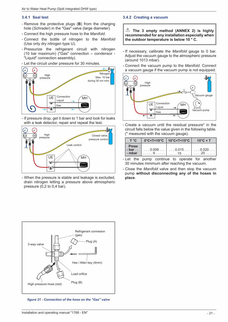
figure 21 - Connection of the hose on the "Gaz" valve
Refrigerant connexion (gas)
Plug (A)
Hex / Allen key (4mm)
3-way valve
Load orifice
Plug (B)High pressure hose (red)
Installation and operating manual "1768 - EN" - 21 -
Air to Water Heat Pump (Split integrated DHW type)
3 .4 .3 Filling the installation with gas
If an additional charge is requires, add the additional charge before filling the hydraulic unit with gas. Please refer to the para . "Additional charge", page 22 .
- Remove the access plugs (A) from the valve controls. - First of all fully open the "Liquid" valve (small) and then the "Gas" valve (large) using a hex key (counterclockwise direction) without forcing excessively against the stop. - Remove the hose rapidly to the Manifold - Refit the 2 original caps (be sure they are clean) and tighten them to the recommended tightening torque (figure 18, page 18). The sealing is performed in the caps only metal to metal.
The outdoor unit does not contain any additional refrigerant, enabling the installation to be purged.Flushing is strictly forbidden.
3 .4 .4 Sealing testThe sealing test must be performed with a certified gas detector (sensitivity 5g/year).Once the refrigerant circuit has been gassed as described above, check that all the refrigerant connectors are gas-tight (4 connectors). If the flarings have been made correctly, there should be no leaks. Eventually, check the tightness of the refrigerant valves caps.
" If there is a leak: - Bring the gas into the outdoor unit (pump down). The pressure should not drop below atmospheric pressure (0 bar to read on Manifold) so as not to contaminate the recovered gas with air or moisture. - Make the connection again. - Repeat the commissioning procedure.
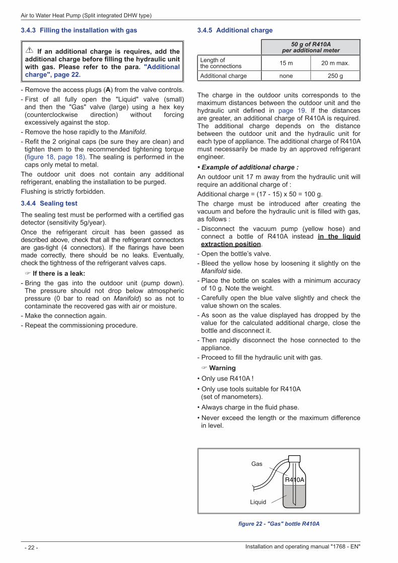
R410A
figure 22 - "Gas" bottle R410A
Gas
Liquid
3 .4 .5 Additional charge
50 g of R410A per additional meter
Length of the connections 15 m 20 m max.
Additional charge none 250 g
The charge in the outdoor units corresponds to the maximum distances between the outdoor unit and the hydraulic unit defined in page 19. If the distances are greater, an additional charge of R410A is required. The additional charge depends on the distance between the outdoor unit and the hydraulic unit for each type of appliance. The additional charge of R410A must necessarily be made by an approved refrigerant engineer.• Example of additional charge :An outdoor unit 17 m away from the hydraulic unit will require an additional charge of :Additional charge = (17 - 15) x 50 = 100 g.The charge must be introduced after creating the vacuum and before the hydraulic unit is filled with gas, as follows : - Disconnect the vacuum pump (yellow hose) and connect a bottle of R410A instead in the liquid extraction position - Open the bottle’s valve. - Bleed the yellow hose by loosening it slightly on the Manifold side. - Place the bottle on scales with a minimum accuracy of 10 g. Note the weight. - Carefully open the blue valve slightly and check the value shown on the scales. - As soon as the value displayed has dropped by the value for the calculated additional charge, close the bottle and disconnect it. - Then rapidly disconnect the hose connected to the appliance. - Proceed to fill the hydraulic unit with gas.
" Warning• Only use R410A !• Only use tools suitable for R410A
(set of manometers).• Always charge in the fluid phase.• Never exceed the length or the maximum difference
in level.
Installation and operating manual "1768 - EN"
Air to Water Heat Pump (Split integrated DHW type)
- 22 -
DIP SW
Interface card
LED2 (green)LED1 (red)
OFFON
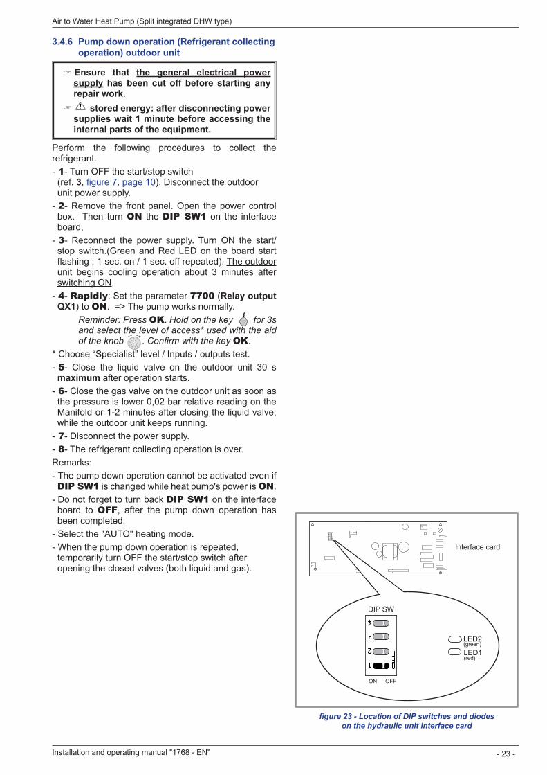
figure 23 - Location of DIP switches and diodes on the hydraulic unit interface card
3 .4 .6 Pump down operation (Refrigerant collecting operation) outdoor unit
" Ensure that the general electrical power supply has been cut off before starting any repair work. " stored energy: after disconnecting power supplies wait 1 minute before accessing the internal parts of the equipment .
Perform the following procedures to collect the refrigerant. - 1- Turn OFF the start/stop switch (ref. 3, figure 7, page 10). Disconnect the outdoor unit power supply. - 2- Remove the front panel. Open the power control box. Then turn ON the DIP SW1 on the interface board, - 3- Reconnect the power supply. Turn ON the start/stop switch.(Green and Red LED on the board start flashing ; 1 sec. on / 1 sec. off repeated). The outdoor unit begins cooling operation about 3 minutes after switching ON - 4- Rapidly: Set the parameter 7700 (Relay output QX1) to ON. => The pump works normally.
Reminder: Press OK Hold on the key for 3s and select the level of access* used with the aid of the knob Confirm with the key OK
* Choose “Specialist” level / Inputs / outputs test. - 5- Close the liquid valve on the outdoor unit 30 s maximum after operation starts. - 6- Close the gas valve on the outdoor unit as soon as the pressure is lower 0,02 bar relative reading on the Manifold or 1-2 minutes after closing the liquid valve, while the outdoor unit keeps running. - 7- Disconnect the power supply. - 8- The refrigerant collecting operation is over.
Remarks: - The pump down operation cannot be activated even if DIP SW1 is changed while heat pump's power is ON - Do not forget to turn back DIP SW1 on the interface board to OFF, after the pump down operation has been completed. - Select the "AUTO" heating mode. - When the pump down operation is repeated, temporarily turn OFF the start/stop switch after opening the closed valves (both liquid and gas).
Installation and operating manual "1768 - EN" - 23 -
Air to Water Heat Pump (Split integrated DHW type)
" GeneralThe connection must comply with good trade practice according to local building regulations.Reminder: Seal everything when fitting in accordance with prevailing trade practice for plumbing work: - Use suitable seals (fibre seals, o-rings). - Use Teflon tape or hemp. - Use sealing paste (synthetic depending on the case).
Use glycol if the flow temperature set [908-909 Settings] <10 ° C. If you are using a glycol/water mix, provide for an annual check on the quantity of glycol. Use monopropylene glycol only. The recommended concentration is 30% minimum. Never use monoethylene glycol .
" In certain installations, the presence of different metals can cause corrosion problems; the formation of metal particles and sludge in the hydraulic circuit is then seen . " In this case, it is advisable to use a corrosion inhibitor in the proportions indicated by its manufacturer .
- Please refer to the chapter "Treatment of domestic and heating water" in our price catalogue.
" It is also necessary to ensure that the treated water does not become aggressive.
4 .1 Connecting to the Heating circuit
4 .1 .1 Rinsing out the installationBefore connecting the hydraulic unit to the installation, rinse out the heating system correctly to eliminate any particles that may affect the appliance's correct operation.Do not use solvents or aromatic hydrocarbons (petrol, paraffin, etc.).In the case of an old installation, provide a sufficiently large decanting pot with a drain on the return from the boiler and at the lowest point in the system in order to collect and remove the impurities.Add an alkaline product to the water and a dispersant.Rinse the installation several times before filling it definitively.
4 .1 .2 ConnectingThe heating circulating pump is built into the hydraulic unit.Connect the central heating pipes to the appliance, complying with the direction of circulation.The pipe between the heat pump and the heat collector must be at least one inch in diameter (26x34 mm).Calculate the diameter of the pipes according to the flow rates and the lengths of the hydraulic systems.Tightening torque: 15 to 35 Nm.Use union connectors to facilitate removing the hydraulic unit.Preferentially use connection hoses to avoid transmitting noise and vibrations to the building.Connect the drains from the drain valve and the safety valve to the main sewer system.Verify the correct functioning of the expansion system. Control the vessel pressure (precharge 1 bar) and the safety valve setting.The flow of the installation must be at least equal to the minimum value noted in the characteristics table (section 1.3, page 5). Do not instal any regulating appliance (without those present in our configurations) who's reduce or stop the flow through the hydraulic unit.
4 Hydraulic connecting
Installation and operating manual "1768 - EN"
Air to Water Heat Pump (Split integrated DHW type)
- 24 -
R1
D
MT
CAR
GS
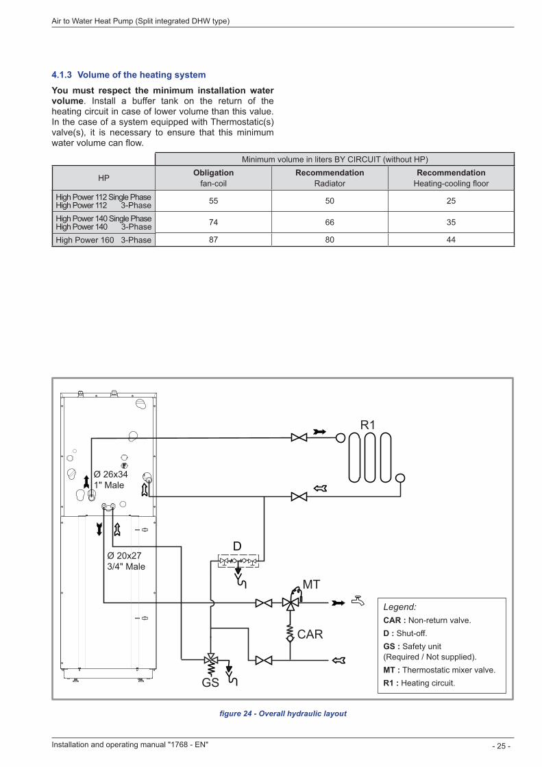
figure 24 - Overall hydraulic layout
Legend:CAR : Non-return valve.D : Shut-off.GS : Safety unit (Required / Not supplied).MT : Thermostatic mixer valve.R1 : Heating circuit.
Ø 26x341" Male
Ø 20x273/4" Male
4 .1 .3 Volume of the heating systemYou must respect the minimum installation water volume. Install a buffer tank on the return of the heating circuit in case of lower volume than this value. In the case of a system equipped with Thermostatic(s) valve(s), it is necessary to ensure that this minimum water volume can flow.
Minimum volume in liters BY CIRCUIT (without HP)
HP Obligationfan-coil
RecommendationRadiator
RecommendationHeating-cooling floor
excellia duo 11 excellia duo tri 11 55 50 25
excellia duo 14 excellia duo tri 14 74 66 35
excellia duo tri 16 87 80 44
Installation and operating manual "1768 - EN" - 25 -
Air to Water Heat Pump (Split integrated DHW type)
High Power 112 Single Phase High Power 112 3-PhaseHigh Power 140 Single Phase High Power 140 3-PhaseHigh Power 160 3-Phase
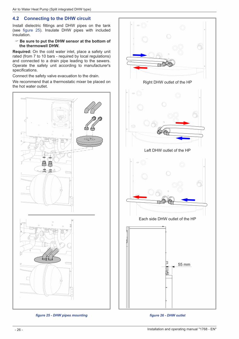
4 .2 Connecting to the DHW circuitInstall dielectric fittings and DHW pipes on the tank (see figure 25). Insulate DHW pipes with included insulation.
" Be sure to put the DHW sensor at the bottom of the thermowell DHW.
Required: On the cold water inlet, place a safety unit rated (from 7 to 10 bars - required by local regulations) and connected to a drain pipe leading to the sewers. Operate the safety unit according to manufacturer's specifications.Connect the safety valve evacuation to the drain.We recommend that a thermostatic mixer be placed on the hot water outlet.
figure 25 - DHW pipes mounting
Right DHW outlet of the HP
Left DHW outlet of the HP
Each side DHW outlet of the HP
55 mm
figure 26 - DHW outlet
Installation and operating manual "1768 - EN"
Air to Water Heat Pump (Split integrated DHW type)
- 26 -
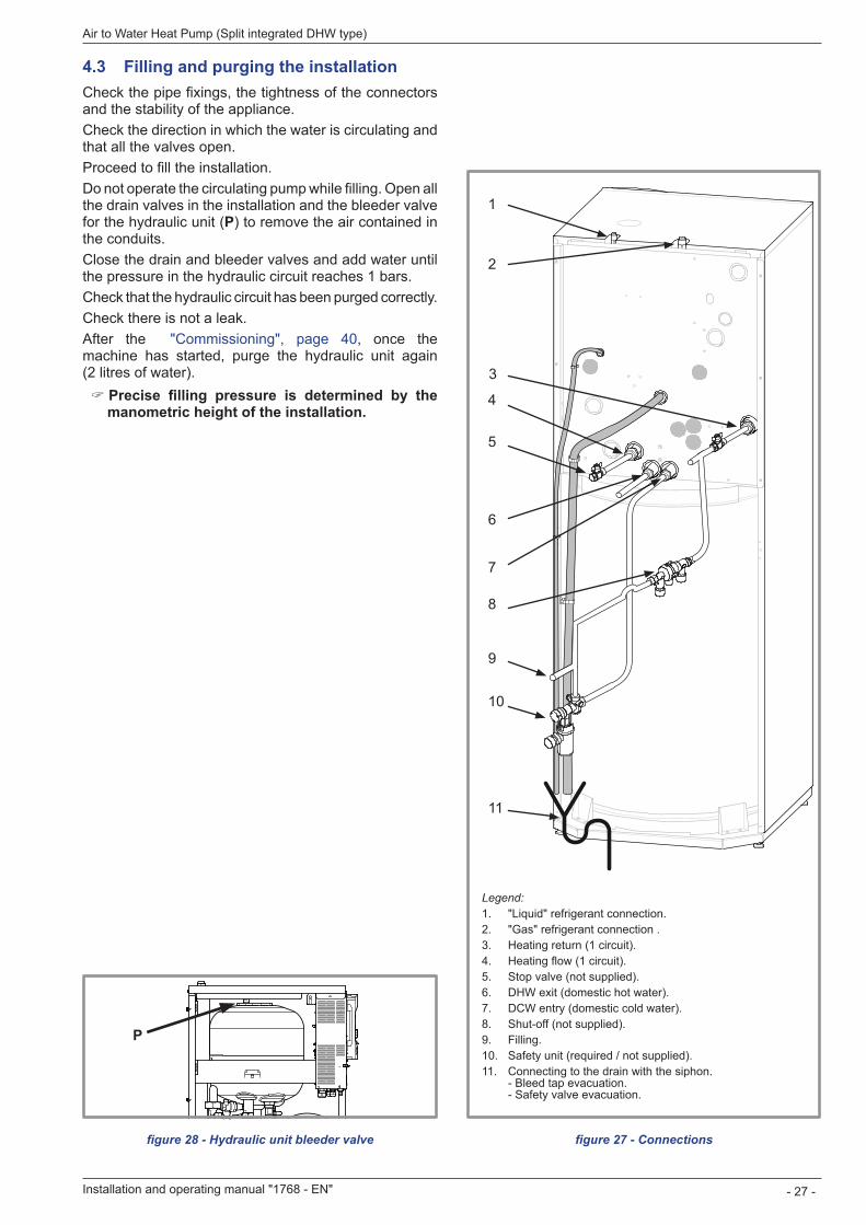
figure 27 - Connections
1
2
3
5
4
6
7
8
9
10
11
Legend:1 "Liquid" refrigerant connection.2 "Gas" refrigerant connection .3 Heating return (1 circuit).4 Heating flow (1 circuit).5 Stop valve (not supplied).6 DHW exit (domestic hot water).7 DCW entry (domestic cold water).8 Shut-off (not supplied).9 Filling.10 Safety unit (required / not supplied).11 Connecting to the drain with the siphon.
- Bleed tap evacuation. - Safety valve evacuation.
4 .3 Filling and purging the installationCheck the pipe fixings, the tightness of the connectors and the stability of the appliance.Check the direction in which the water is circulating and that all the valves open.Proceed to fill the installation.Do not operate the circulating pump while filling. Open all the drain valves in the installation and the bleeder valve for the hydraulic unit (P) to remove the air contained in the conduits.Close the drain and bleeder valves and add water until the pressure in the hydraulic circuit reaches 1 bars. Check that the hydraulic circuit has been purged correctly.Check there is not a leak.After the "Commissioning", page 40, once the machine has started, purge the hydraulic unit again (2 litres of water).
" Precise filling pressure is determined by the manometric height of the installation .
figure 28 - Hydraulic unit bleeder valve
P
Installation and operating manual "1768 - EN" - 27 -
Air to Water Heat Pump (Split integrated DHW type)
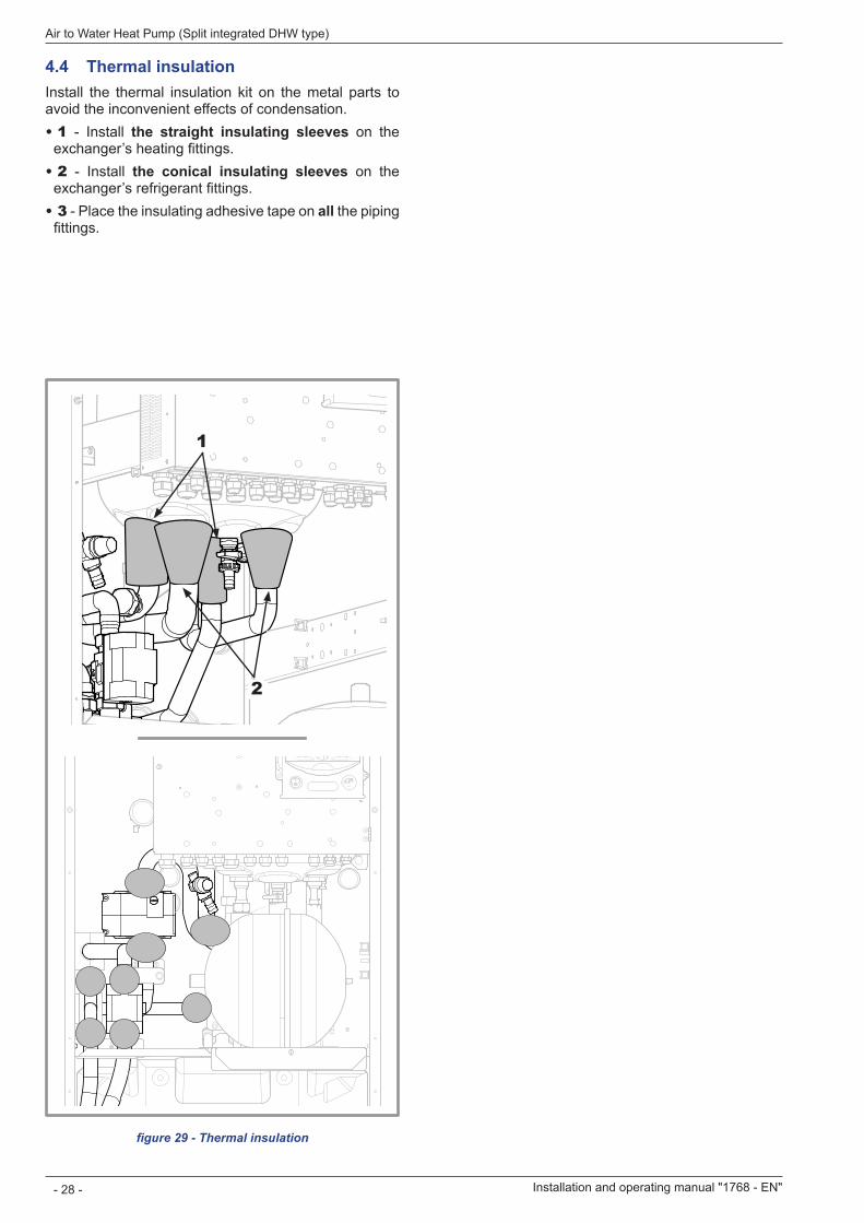
figure 29 - Thermal insulation
1
2
4 .4 Thermal insulationInstall the thermal insulation kit on the metal parts to avoid the inconvenient effects of condensation.• 1 - Install the straight insulating sleeves on the
exchanger’s heating fittings.• 2 - Install the conical insulating sleeves on the
exchanger’s refrigerant fittings.• 3 - Place the insulating adhesive tape on all the piping
fittings.
Installation and operating manual "1768 - EN"
Air to Water Heat Pump (Split integrated DHW type)
- 28 -
4 .5 Heating circulation pump speed settings
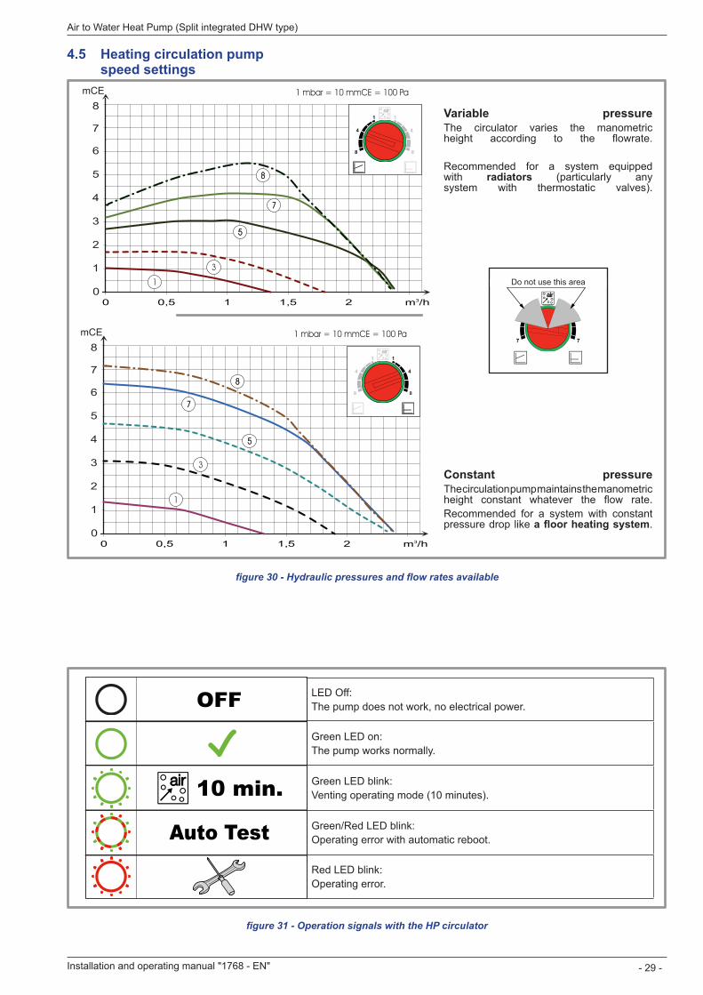
figure 30 - Hydraulic pressures and flow rates available
0
1
2
3
4
5
6
7
8mCE 1 mbar = 10 mmCE = 100 Pa
m /h31 1,5 20,500 0,5 1 1,5 2 m3/h
1
3
55
77
88
0
1
2
3
4
5
6
7
8mCE 1 mbar = 10 mmCE = 100 Pa
m /h31 1,5 20,500 0,5 1 1,5 2 m3/h
1
3
55
77
88
Variable pressureThe circulator varies the manometric height according to the flowrate.
Recommended for a system equipped with radiators (particularly any system with thermostatic valves).
Constant pressureThe circulation pump maintains the manometric height constant whatever the flow rate.Recommended for a system with constant pressure drop like a floor heating system
figure 31 - Operation signals with the HP circulator
LED Off:The pump does not work, no electrical power.
Green LED on:The pump works normally.
Green LED blink:Venting operating mode (10 minutes).
Green/Red LED blink:Operating error with automatic reboot.
Red LED blink:Operating error.
Ne pas utiliser cette zoneDo not use this area
Installation and operating manual "1768 - EN" - 29 -
Air to Water Heat Pump (Split integrated DHW type)
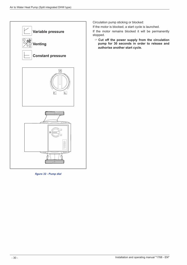
Circulation pump sticking or blocked:If the motor is blocked, a start cycle is launched.If the motor remains blocked it will be permanently stopped.
" Cut off the power supply from the circulation pump for 30 seconds in order to release and authorise another start cycle .
figure 32 - Pump dial
Pression variable
Dégazage
Pression constate
Variable pressure
Venting
Constant pressure
Installation and operating manual "1768 - EN"
Air to Water Heat Pump (Split integrated DHW type)
- 30 -
Installation and operating manual "1768 - EN" - 31 -
Air to Water Heat Pump (Split integrated DHW type)
Ensure that the general electrical power supply has been cut off before starting any repair work.
5 .1 General
5 .1 .1 Characteristic of the electrical supplyThe electrical installation must be conducted in accordance with the prevailing regulations.The electrical connections must only be made when all the other fitting operations have been completed (fixing, assembly, etc.).
" Warning !The contract concluded with the energy provider must be sufficient not only to cover the heat pump's power but also the combined sum of all the appliances likely to be operating at the same time. When the power is too low, check with your energy provider the value subscribed to in your contract.Never use a socket for the power supply.The heat pump must be supplied directly (without external switch) with power by special protected leads from the electric panel via 2-pole circuit breakers specially dedicated to the heat pump, Curve D for the outdoor unit, curve C for the electrical heating and domestic water back-ups (see tables on page 33).The electrical installation must necessarily be equipped with a 30mA differential protection.This appliance is designed to operate under a nominal voltage of 230 V or 400 V +/- 10%, 50 Hz (according to model).
5 .1 .2 General remarks on electrical connectionsIt is essential to maintain the live-neutral polarity when making the electrical connections.Rigid wires are preferable for fixed installations, particularly in a building.Tighten the cables using the cable glands to prevent the conductors from disconnecting accidentally.Connection to Earth and Earth bonding continuity are essential.
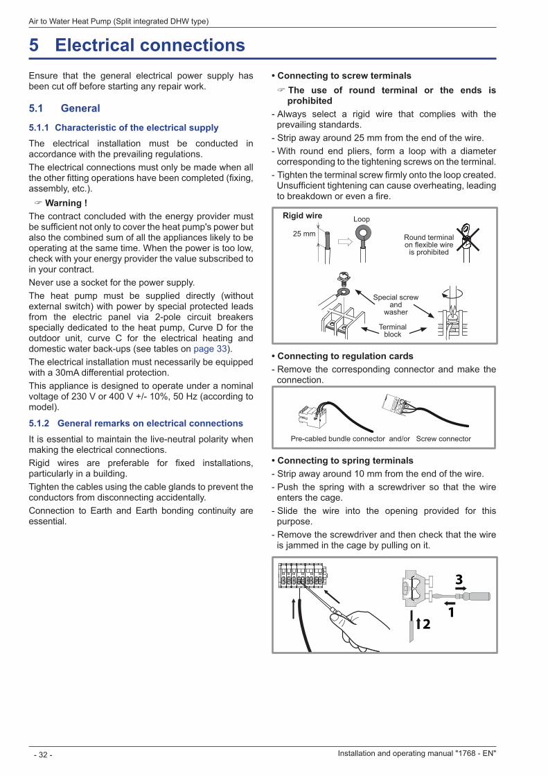
• Connecting to screw terminals " The use of round terminal or the ends is prohibited
- Always select a rigid wire that complies with the prevailing standards. - Strip away around 25 mm from the end of the wire. - With round end pliers, form a loop with a diameter corresponding to the tightening screws on the terminal. - Tighten the terminal screw firmly onto the loop created. Unsufficient tightening can cause overheating, leading to breakdown or even a fire.
Rigid wire Loop
25 mm Round terminal on flexible wire
is prohibited
Special screw and
washer
Terminal block
• Connecting to regulation cards - Remove the corresponding connector and make the connection.
• Connecting to spring terminals - Strip away around 10 mm from the end of the wire. - Push the spring with a screwdriver so that the wire enters the cage. - Slide the wire into the opening provided for this purpose. - Remove the screwdriver and then check that the wire is jammed in the cage by pulling on it.
21
3
Pre-cabled bundle connector and/or Screw connector
5 Electrical connections
Installation and operating manual "1768 - EN"
Air to Water Heat Pump (Split integrated DHW type)
- 32 -
5 .2 Cable section and protection ratingThe cable sections are given for information purposes only and do not exempt the installer from checking that these sections correspond to the requirements and comply with the prevailing standards.• Power supply to outdoor unit
Heat pump (single phase) Electricity supply 230 V - 50 Hz
Model Maxi. power absorbed Cable connection (phase, neutral, earth) Curve D circuit breaker size
excellia duo 11 Single phase 5060 W3 x 6 mm² 32 A
excellia duo 14 Single phase 5750 W
Heat pump (3-phase) Electricity supply 400 V - 50 Hz
Model Maxi. power absorbed Cable connection (3 phases, neutral, earth) Curve D circuit breaker size
excellia duo 11 3-phase 5865 W5 x 2,5 mm² 20 Aexcellia duo 14 3-phase 6555 W
excellia duo 16 3-phase 7245 W
• Interconnection between the outdoor unit and the hydraulic unit: The hydraulic unit is powered by the outdoor unit by means of a cable with 4 x 1,5 mm² (phase, neutral, earth, communication bus).
• Electricity supply DHW: The DHW section is powered directly via a 3 x 1,5 mm² cable (phase, neutral, earth). Protection by circuit breaker (16 A, curve C).
• Power supply to the electrical back-ups (option)The hydraulic unit contains two stages of electrical back-ups installed in a heat exchange tank.
Heat pump (HP) Electrical back-ups Power supply to the electrical back-ups
Model Power Nominal current Cable connection Curve C circuit breaker size
excellia duo Single phase 2 x 3 kW 26,1 A 3 x 6 mm² 32 Aexcellia duo 3-phase 9 kW 3 x 13 A 4 x 2,5 mm² 20 A
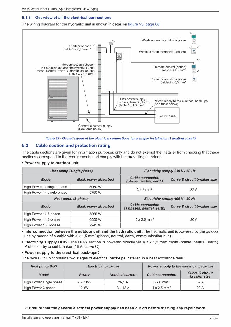
figure 33 - Overall layout of the electrical connections for a simple installation (1 heating circuit)
" Ensure that the general electrical power supply has been cut off before starting any repair work.
5 .1 .3 Overview of all the electrical connectionsThe wiring diagram for the hydraulic unit is shown in detail on figure 53, page 66
Outdoor sensor Cable 2 x 0,75 mm²
Interconnection between the outdoor unit and the hydraulic unit :
Phase, Neutral, Earth, Communication bus Cable 4 x 1,5 mm²
Room control unit T78 (option)
Room thermostat T58 (option)
Room control unit T75 (option) Cable 3 x 0,5 mm²
Room thermostat T55 (option) Cable 2 x 0,5 mm²
Power supply to the electrical back-ups (Phase, Neutral, Earth) Cable 3 x 6 mm²
DHW power supply (Phase, Neutral, Earth) Cable 3 x 1,5 mm²
General power supply (Phase, Neutral, Earth) (depending on heat pump power)
Electric panel
or
or
or
Installation and operating manual "1768 - EN" - 33 -
Air to Water Heat Pump (Split integrated DHW type)
High Power 11 single phaseHigh Power 14 single phase
High Power 11 3-phaseHigh Power 14 3-phaseHigh Power 16 3-phase
High Power single phaseHigh Power 3-phase
Outdoor sensor Cable 2 x 0,75 mm²
Interconnection between the outdoor unit and the hydraulic unit :
Phase, Neutral, Earth, Communication bus Cable 4 x 1,5 mm²
Wireless remote control (option)
Wireless room thermostat (option)
Remote control (option) Cable 3 x 0,5 mm²
Room thermostat (option) Cable 2 x 0,5 mm²
Power supply to the electrical back-ups (See table below)
DHW power supply (Phase, Neutral, Earth) Cable 3 x 1,5 mm²
General electrical supply (See table below)
Electric panel
or
or
or
:
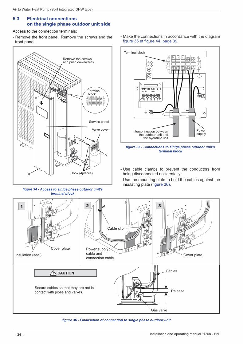
5 .3 Electrical connections on the single phase outdoor unit sideAccess to the connection terminals: - Remove the front panel. Remove the screws and the front panel.
figure 34 - Access to sinlge phase outdoor unit’s terminal block
figure 35 - Connections to sinlge phase outdoor unit’s terminal block
figure 36 - Finalisation of connection to single phase outdoor unit
- Make the connections in accordance with the diagram figure 35 et figure 44, page 39
- Use cable clamps to prevent the conductors from being disconnected accidentally. - Use the mounting plate to hold the cables against the insulating plate (figure 36)
Remove the screws and push downwards
Service panel
Valve cover
Hook (4places)
Terminal block
Terminal block
Interconnection between the outdoor unit and
the hydraulic unit
Power supply
Cover plate
Insulation (seal)Power supply cable and connection cable
Cable clip
Cover plate
CAUTION
Release
Cables
Gas valve
Secure cables so that they are not in contact with pipes and valves.
1 2 3
Installation and operating manual "1768 - EN"
Air to Water Heat Pump (Split integrated DHW type)
- 34 -
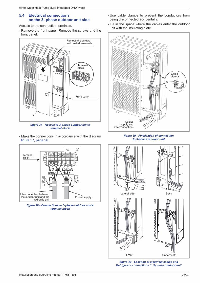
5 .4 Electrical connections on the 3- phase outdoor unit sideAccess to the connection terminals. - Remove the front panel. Remove the screws and the front panel.
- Make the connections in accordance with the diagram figure 37, page 26
- Use cable clamps to prevent the conductors from being disconnected accidentally. - Fill in the space where the cables enter the outdoor unit with the insulating plate.
figure 37 - Access to 3-phase outdoor unit’s terminal block
figure 38 - Connections to 3-phase outdoor unit’s terminal block
figure 39 - Finalisation of connection to 3-phase outdoor unit
figure 40 - Location of electrical cables and Refrigerant connections to 3-phase outdoor unit
Remove the screws and push downwards
Front panel
Terminal block
Cable clamps
Cables (supply and
interconnection)
1INDOOR UNIT POWER
2 3 L1 L2 L3 N
Terminal block
Interconnection between the outdoor unit and the
hydraulic unitPower supply
Front Underneath
Lateral side Back
Installation and operating manual "1768 - EN" - 35 -
Air to Water Heat Pump (Split integrated DHW type)
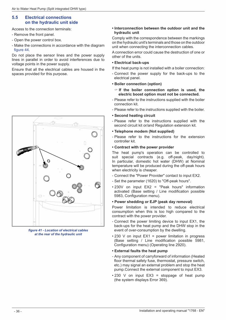
5 .5 Electrical connections on the hydraulic unit sideAccess to the connection terminals: - Remove the front panel. - Open the power control box. - Make the connections in accordance with the diagram figure 44
Do not place the sensor lines and the power supply lines in parallel in order to avoid interferences due to voltage points in the power supply.Ensure that all the electrical cables are housed in the spaces provided for this purpose.
• Interconnection between the outdoor unit and the hydraulic unit
Comply with the correspondence between the markings on the hydraulic unit's terminals and those on the outdoor unit when connecting the interconnection cables.A connection error could cause the destruction of one or other of the units.• Electrical back-ups (option)If the heat pump is not installed with a boiler connection: - Connect the power supply for the back-ups to the electrical panel.
• Boiler connection (option) " If the boiler connection option is used, the electric boost option must not be connected .
- Please refer to the instructions supplied with the boiler connection kit. - Please refer to the instructions supplied with the boiler.
• Second heating circuit - Please refer to the instructions supplied with the second circuit kit or/and Regulation extension kit.
• Telephone modem (Not supplied) - Please refer to the instructions for the extension controller kit.
• Contract with the power providerThe heat pump's operation can be controlled to suit special contracts (e.g. off-peak, day/night). In particular, domestic hot water (DHW) at Nominal temperature will be produced during the off-peak hours when electricity is cheaper. - Connect the "Power Provider" contact to input EX2. - Set the parameter (1620) to "Off-peak hours".
• 230V on input EX2 = "Peak hours" information activated (Base setting / Line modification possible 5983, Configuration menu).
• Power shedding or EJP (peak day removal)Power limitation is intended to reduce electrical consumption when this is too high compared to the contract with the power provider. - Connect the power limiting device to input EX1, the back-ups for the heat pump and the DHW stop in the event of over-consumption by the dwelling.
• 230 V on input EX1 = power limitation in progress (Base setting / Line modification possible 5981, Configuration menu) (Operating line 2920).
• External faults the heat pump - Any component of carryforward of information (Heated floor thermal safety fuse, thermostat, pressure switch, etc.) may signal an external problem and stop the heat pump.Connect the external component to input EX3.
• 230 V on input EX3 = stoppage of heat pump (the system displays Error 369).
Installation and operating manual "1768 - EN"
Air to Water Heat Pump (Split integrated DHW type)
- 36 -
figure 41 - Location of electrical cables at the rear of the hydraulic unit
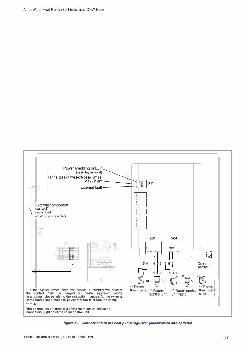
figure 42 - Connections to the heat pump regulator (accessories and options)
EX1EX2EX3
X86
L
X84
X11
6545 6
M B91
12 1 3 2
654
13 2
Power shedding or EJP(peak day removal)
Tariffs, peak times/off-peak times,day / night
External fault
** RoomthermostatT55
** Roomthermostatradio T58
Outdoorsensor
** Roomcontrol unitT75
** Room controlunit radio T78
External componentcontact*(faults, loadshedder, power meter)
or oror
* If the control device does not provide a potential-free contact, the contact must be relayed to create equivalent wiring. In all cases, please refer to the instruction manuals for the external components (load shedder, power meters) to create the wiring.** OptionT75 : The connection of terminal 3 of the room control unit T75 is not mandatory (lighting of the room control unit.
Installation and operating manual "1768 - EN" - 37 -
Air to Water Heat Pump (Split integrated DHW type)
* If the control device does not provide a potential-free contact, the contact must be relayed to create equivalent wiring. In all cases, please refer to the instruction manuals for the external components (load shedder, power meters) to create the wiring.** OptionThe connection of terminal 3 of the room control unit is not mandatory (lighting of the room control unit.
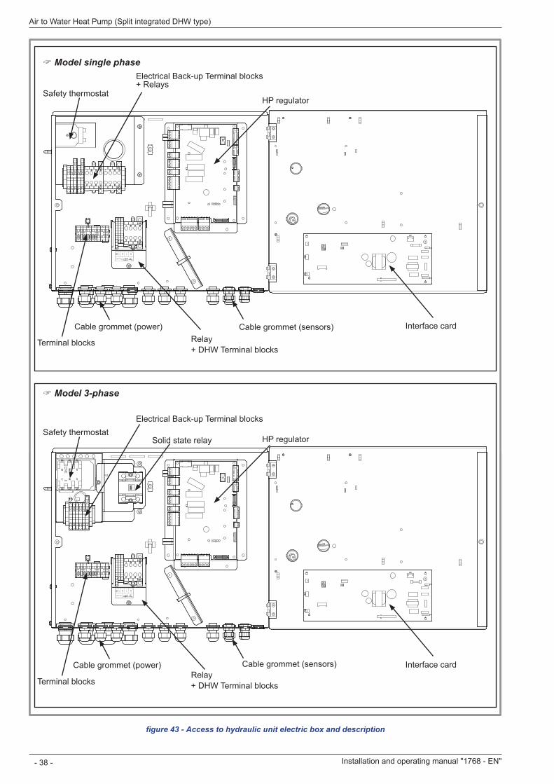
figure 43 - Access to hydraulic unit electric box and description
230 V
L N L N2 4
HP regulator
Cable grommet (Power)
Interface cardCable grommet (sensors)
Relay + DHW Terminal blocks
Terminal blocks
Installation and operating manual "1768 - EN"
Air to Water Heat Pump (Split integrated DHW type)
- 38 -
230 V
L N L N2 4
230 V
L N L N2 4
Relay + DHW Terminal blocks
Relay + DHW Terminal blocks
HP regulator
Electrical Back-up Terminal blocks
Solid state relaySafety thermostat
Cable grommet (power) Interface cardCable grommet (sensors)
Terminal blocks
" Model 3-phase
HP regulator
Electrical Back-up Terminal blocks + Relays
Safety thermostat
Cable grommet (power) Interface cardCable grommet (sensors)
Terminal blocks
" Model single phase
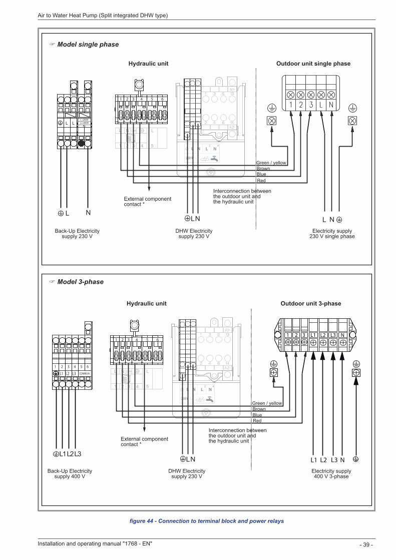
figure 44 - Connection to terminal block and power relays
230 V
L N L N2 4
LN
1 2 3 4 5 6
L N
230 V
L N L N2 4
LN
1 2 3 4 5 61 2 3 L1 L2 L3 N
L1 L2 L3 N
Outdoor unit single phase
Outdoor unit 3-phase
Hydraulic unit
Hydraulic unit
Power supply 230 V single phase
Power supply 400 V 3-phase
DHW power supply 230 V
DHW power supply 230 V
External component contact *
External component contact *
Red
Red
Blue
Blue
Brown
Brown
Green / yellow
Green / yellow
Interconnection between the outdoor unit and the hydraulic unit
Interconnection between the outdoor unit and the hydraulic unit
" Model single phase
" Model 3-phase
Installation and operating manual "1768 - EN" - 39 -
Air to Water Heat Pump (Split integrated DHW type)
230 V
L N L N2 4
LN
1 2 3 4 5 6
L NL N
230 V
L N L N2 4
LN
1 2 3 4 5 61 2 3 L1 L2 L3 N
L1 L2 L3 N
1 2 3 4 5 6
L1 L2 L3 COMMUN
L1 L2 L3
Outdoor unit single phase
Outdoor unit 3-phase
Hydraulic unit
Hydraulic unit
Electricity supply 230 V single phase
Electricity supply 400 V 3-phase
Back-Up Electricity supply 230 V
DHW Electricity supply 230 V
DHW Electricity supply 230 V
Back-Up Electricity supply 400 V
External component contact *
External component contact *
Red
Red
Blue
Blue
Brown
Brown
Green / yellow
Green / yellow
Interconnection between the outdoor unit and the hydraulic unit
Interconnection between the outdoor unit and the hydraulic unit
" Model single phase
" Model 3-phase
5 .6 Outdoor sensorThe outdoor sensor is required for the heat pump to operate correctly.Consult the fitting instructions on the packaging.Place the sensor on the coldest part, generally the northern or north-eastern side.In any case, it must not be exposed to the morning sun.It must be installed so as to be easily accessible but at least 2,5 m from the floor.It is essential that it avoid any sources of heat such as flues, the upper parts of doors and windows, proximity to extraction vents, the underneath of balconies and under-eave areas, which would isolate the sensor from variations in the outdoor air temperature. - Connect the outdoor sensor to the connector X84 (terminals M and B9) on the heat pump control board.
5 .7 Room thermostat and/or room control unitThe room thermostat (room control unit) is optional.Consult the fitting instructions on the packaging.The sensor must be installed in the living room area on a very uncluttered wall. It must be installed so as to be easily accessible.Avoid direct sources of heat (chimney/flue, television, cooking hobs), draughty areas (ventilation, door, etc.).Air leaks in the seals in the constructions are often translated into cold air blowing through the electrical conduits. Lag the electrical conduits if there is a cold draught on the back of the IR sensor.
5 .7 .1 Installing a room sensor
• Room thermostat T55 - Connect the sensor to the X86 connector of the heat pump’s regulator board using the connector provided (terminals 1, 2).
• Room thermostat radio T58 - Please refer to the instructions .
5 .7 .2 Installing a room control unit
• Room control unit T75 - Connect the sensor to the X86 connector of the heat pump’s regulator board using the connector provided (terminals 1, 2 and 3).
• Room control unit radio T78 - Please refer to the instructions .
5 .7 .3 Fan convectors or dynamic radiators areaIf the installation is equipped with fan convector or dynamic radiators, Do not use a room sensor in the area
6 Commissioning - Close the installation's main circuit breaker.
On first commissioning (or in winter), in order to allow the compressor to pre-heat, engage the installation's main circuit breaker (power supply to the outdoor unit) some hours before starting up the tests.
- Engage the start/stop switch.To ensure that inputs EX1, EX2 and EX3 operate correctly: Check that the live-neutral polarity of the power supply is correct.
When the power is switched on and every time that the ON/OFF button is switched off and then switched on again, the outdoor unit will take approximately 4 minutes to start up, even if the setting is requesting heating.
The display can show error 370 when the appliance (re)starts. Do not be concerned, the communication between the outdoor and hydraulic unit will re-establish itself in a few moments.
During the regulator initialisation phase, the display shows all the symbols and then "Data, update" and then "State heat pump". - Make all the specific adjustments to the setting. (Installation configuration):
- Press OK
- Hold down the key for 3s and select the level of access used with the aid of the knob.
- Confirm with the key OK
- Parameter the heat pump's setting (Consult the settings' list page 35).
On commissioning (or the case of error 10), the electrical back-up heaters are liable to start up even if the outdoor temperature at the time is above the heaters’ trigger temperature.The regulating system uses an average initial outdoor temperature of 0°C and requires some time to update this temperature.To avoid this situation, the sensor must be connected correctly. Re-initialise parameter 8703 (commissioning level, consumer diagnostic menu).
Installation and operating manual "1768 - EN"
Air to Water Heat Pump (Split integrated DHW type)
- 40 -
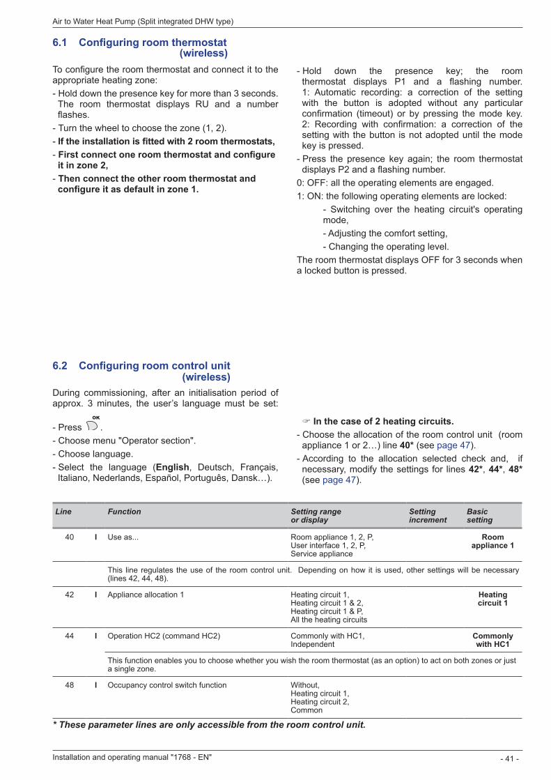
6 .1 Configuring room thermostat
To configure the room thermostat and connect it to the appropriate heating zone: - Hold down the presence key for more than 3 seconds. The room thermostat displays RU and a number flashes. - Turn the wheel to choose the zone (1, 2). - If the installation is fitted with 2 room thermostats, - First connect one room thermostat and configure it in zone 2, - Then connect the other room thermostat and configure it as default in zone 1.
" In the case of 2 heating circuits . - Choose the allocation of the room control unit (room appliance 1 or 2…) line 40* (see page 47). - According to the allocation selected check and, if necessary, modify the settings for lines 42*, 44*, 48* (see page 47).
Line Function Setting range or display
Setting increment
Basic setting
40 I Use as... Room appliance 1, 2, P, User interface 1, 2, P, Service appliance
Room appliance 1
This line regulates the use of the room control unit. Depending on how it is used, other settings will be necessary (lines 42, 44, 48).
42 I Appliance allocation 1 Heating circuit 1, Heating circuit 1 & 2, Heating circuit 1 & P, All the heating circuits
Heating circuit 1
44 I Operation HC2 (command HC2) Commonly with HC1, Independent
Commonly with HC1
This function enables you to choose whether you wish the room thermostat (as an option) to act on both zones or just a single zone.
48 I Occupancy control switch function Without, Heating circuit 1, Heating circuit 2, Common
* These parameter lines are only accessible from the room control unit.
- Hold down the presence key; the room thermostat displays P1 and a flashing number. 1: Automatic recording: a correction of the setting with the button is adopted without any particular confirmation (timeout) or by pressing the mode key. 2: Recording with confirmation: a correction of the setting with the button is not adopted until the mode key is pressed. - Press the presence key again; the room thermostat displays P2 and a flashing number.
0: OFF: all the operating elements are engaged.1: ON: the following operating elements are locked:
- Switching over the heating circuit's operating mode,- Adjusting the comfort setting,- Changing the operating level.
The room thermostat displays OFF for 3 seconds when a locked button is pressed.
6 .2 Configuring room control unit
During commissioning, after an initialisation period of approx. 3 minutes, the user’s language must be set:
- Press OK
- Choose menu "Operator section". - Choose language. - Select the language (English, Deutsch, Français, Italiano, Nederlands, Español, Português, Dansk…).
Installation and operating manual "1768 - EN" - 41 -
Air to Water Heat Pump (Split integrated DHW type)
(wireless)
(wireless)
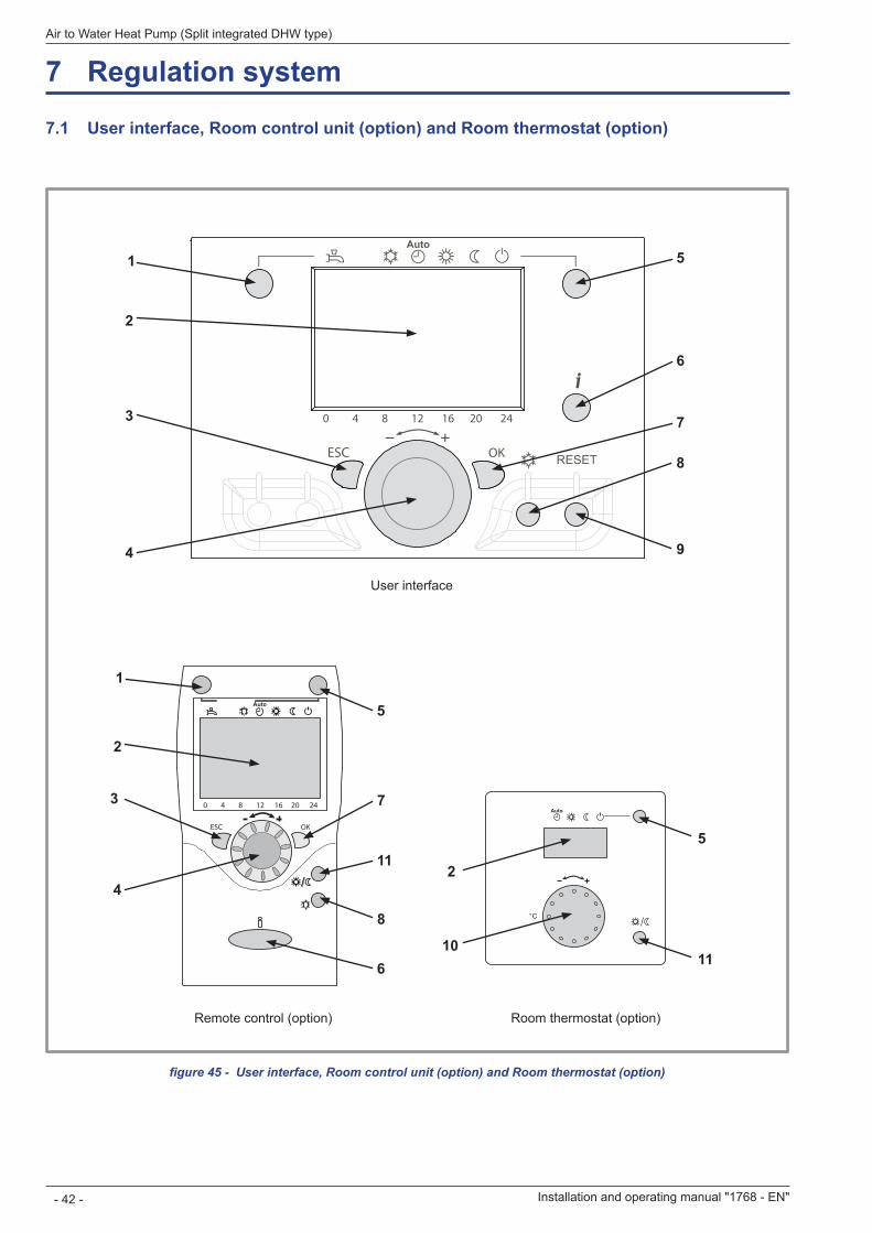
7 Regulation system
7 .1 User interface, Room control unit (option) and Room thermostat (option)
figure 45 - User interface, Room control unit (option) and Room thermostat (option)
°C
Auto
Auto
ESC OK
0 4 8 12 16 20 24
1
2
3
4
5
6
7
8
115
2
1011
Room control unit T75 / T78 Room thermostat T55 / T58
1
2
3
4
5
6
7
8
9
User interface
Installation and operating manual "1768 - EN"
Air to Water Heat Pump (Split integrated DHW type)
- 42 -
Remote control (option) Room thermostat (option)
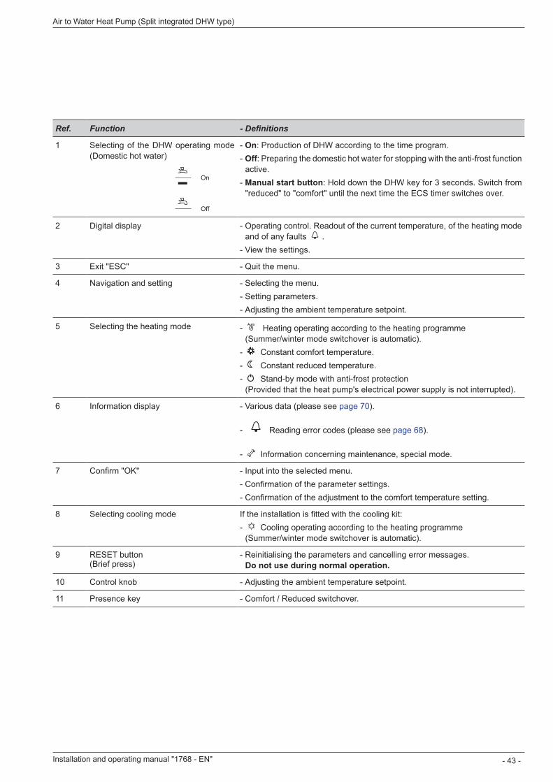
Ref. Function - Definitions
1 Selecting of the DHW operating mode (Domestic hot water)
On
Off
- On: Production of DHW according to the time program. - Off: Preparing the domestic hot water for stopping with the anti-frost function active.
- Manual start button: Hold down the DHW key for 3 seconds. Switch from "reduced" to "comfort" until the next time the ECS timer switches over.
2 Digital display - Operating control. Readout of the current temperature, of the heating mode and of any faults
- View the settings.
3 Exit "ESC" - Quit the menu.
4 Navigation and setting - Selecting the menu. - Setting parameters. - Adjusting the ambient temperature setpoint.
5 Selecting the heating mode - Auto Heating operating according to the heating programme (Summer/winter mode switchover is automatic).
- Constant comfort temperature. - Constant reduced temperature. - Stand-by mode with anti-frost protection (Provided that the heat pump's electrical power supply is not interrupted).
6 Information display - Various data (please see page 70).
- Reading error codes (please see page 68).
- Information concerning maintenance, special mode.
7 Confirm "OK" - Input into the selected menu. - Confirmation of the parameter settings. - Confirmation of the adjustment to the comfort temperature setting.
8 Selecting cooling mode If the installation is fitted with the cooling kit: - Cooling operating according to the heating programme (Summer/winter mode switchover is automatic).
9 RESET button (Brief press)
- Reinitialising the parameters and cancelling error messages. Do not use during normal operation .
10 Control knob - Adjusting the ambient temperature setpoint.
11 Presence key - Comfort / Reduced switchover.
Installation and operating manual "1768 - EN" - 43 -
Air to Water Heat Pump (Split integrated DHW type)
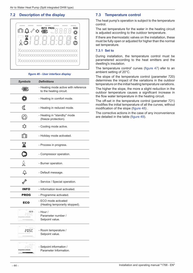
7 .3 Temperature controlThe heat pump's operation is subject to the temperature control.The set temperature for the water in the heating circuit is adjusted according to the outdoor temperature.If there are thermostatic valves on the installation, these must be fully open or adjusted for higher than the normal set temperature.
7 .3 .1 Set toDuring installation, the temperature control must be parametered according to the heat emitters and the dwelling's insulation.The temperature control' curves (figure 47) efer to an ambient setting of 20°C.The slope of the temperature control (parameter 720) determines the impact of the variations in the outdoor temperature on the initial heating temperature variations.The higher the slope, the more a slight reduction in the outdoor temperature causes a significant increase in the flow water temperature in the heating circuit.The off-set in the temperature control (parameter 721) modifies the initial temperature of all the curves, without modification of the slope (figure 48) .The corrective actions in the case of any inconvenience are detailed in the table (figure 49).
7 .2 Description of the display
Symbols Definitions
- Heating mode active with reference to the heating circuit.
- Heating in comfort mode.
- Heating in reduced mode.
- Heating in "standby" mode (freeze protection).
- Cooling mode active.
- Holiday mode activated.
- Process in progress.
- Compressor operation.
- Burner operation.
- Default message.
- Service / Special operation.
INFO - Information level activated.
PROG - Programme activated.
ECO - ECO mode activated (Heating temporarily stopped).
temperature ambiante
- Hour / Parameter number / Setpoint value.
temperature ambiante
- Room temperature / Setpoint value.
temperature ambiante
- Setpoint information / Parameter Information.
figure 46 - User interface display
XxxxxxxxxxxxxxxxxxxxxxxxxxxXxxxxxxxxxxxxxxxxxxxxxxxxxxXxxxxxxxxxxxxxxxxxxxxxxxxxx
Installation and operating manual "1768 - EN"
Air to Water Heat Pump (Split integrated DHW type)
- 44 -
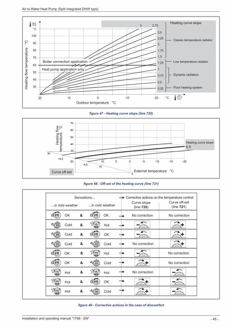
figure 49 - Corrective actions in the case of discomfort
figure 47 - Heating curve slope (line 720)
figure 48 - Off-set of the heating curve (line 721)
40
50
60
70
-20-15-10-5510-4,5
+4,520
0
10
30
0
30
Hea
ting
flow
te
mpe
ratu
re
°C
External temperature °CCurve off-set
Heating curve slope 0,5
&
&
&
&
&
&
&
&
&
Sensations...
...in mild weather ...in cold weatherCurve slope
(line 720)Curve off-set
(line 721)
No correction
No correction
No correction
No correction
No correction
OK OK
OK
OK
OK
OK
Cold
Cold
Cold Cold
Cold
Hot
Hot
HotHot
Hot
Hot Cold
No correction
Corrective actions on the temperature control:
90
80
70
60
50
40
30
° C
100
° C20 -2010
1
0,75
1,75
0,5
0,25
1,25
-100
2
1,5
2,753
2,25
2,5
Heating curve slope
Classic temperature radiator
Dynamic radiators
Low temperature radiator
Floor heating systemHea
ting
flow
tem
pera
ture
°C
Outdoor temperature °C
Boiler connection application
Heat pump application only
Installation and operating manual "1768 - EN" - 45 -
Air to Water Heat Pump (Split integrated DHW type)
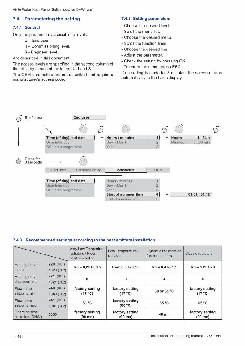
7 .4 Parametering the setting
7 .4 .1 GeneralOnly the parameters accessible to levels:
U – End user. I – Commissioning level.S - Engineer level.
Are described in this document.The access levels are specified in the second column of the table by means of the letters U, I and S The OEM parameters are not described and require a manufacturer's access code.
7 .4 .2 Setting parameters - Choose the desired level. - Scroll the menu list. - Choose the desired menu. - Scroll the function lines. - Choose the desired line. - Adjust the parameter. - Check the setting by pressing OK - To return the menu, press ESC
If no setting is made for 8 minutes, the screen returns automatically to the basic display.
7 .4 .3 Recommended settings according to the heat emitters installation
Very Low Temperture radiators / Floor heating-cooling
Low Temperature radiators
Dynamic radiators or fan coil heaters Classic radiators
Heating curve slope
720 (CC1)from 0,25 to 0,5 from 0,5 to 1,25 from 0,4 to 1,1 from 1,25 to 3
1020 (CC2)
Heating curve displacement
721 (CC1)0 0 4 0
1021 (CC2)
Flow temp setpoint mini
740 (CC1) factory setting (17 °C)
factory setting (17 °C) 30 or 35 °C factory setting
(17 °C)1040 (CC2)
Flow temp setpoint maxi
741 (CC1)50 °C factory setting
(60 °C) 65 °C 65 °C1041 (CC2)
Charging time limitation (DHW) 5030 factory setting
(90 mn)factory setting
(90 mn) 40 mn factory setting (90 mn)
OKBrief press End user
OK OK OK
Time (of day) and date Hours / minutes 1 Hours 1 . . .24 hUser interface Day / Month 2 Minutes 0...60 minCC1 time programme Year 3
Press for 3 seconds
End user Commissioning Specialist OEM
Time (of day) and date Hours / minutes 1User interface Day / Month 2CC1 time programme Year 3 Start of summer time 4 01 .01 . . .31 .12
End of summer time 5
Installation and operating manual "1768 - EN"
Air to Water Heat Pump (Split integrated DHW type)
- 46 -
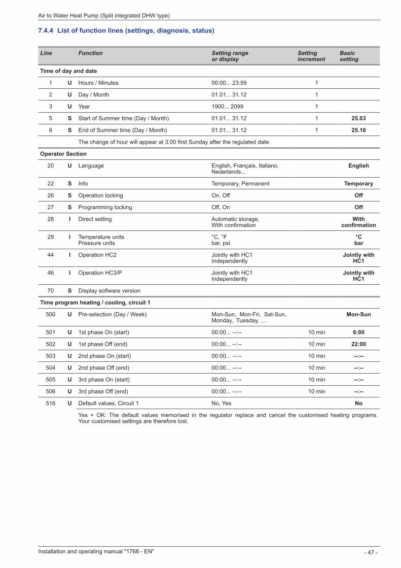
Line Function Setting range or display
Setting increment
Basic setting
Time of day and date
1 U Hours / Minutes 00:00 23:59 1
2 U Day / Month 01 01 31 12 1
3 U Year 1900 2099 1
5 S Start of Summer time (Day / Month) 01 01 31 12 1 25 .03
6 S End of Summer time (Day / Month) 01 01 31 12 1 25 .10
The change of hour will appear at 3:00 first Sunday after the regulated date.
Operator Section
20 U Language English, Français, Italiano,Nederlands...
English
22 S Info Temporary, Permanent Temporary
26 S Operation locking On, Off Off
27 S Programming locking Off, On Off
28 I Direct setting Automatic storage, With confirmation
With confirmation
29 I Temperature units Pressure units
°C, °F bar, psi
°C bar
44 I Operation HC2 Jointly with HC1 Independently
Jointly with HC1
46 I Operation HC3/P Jointly with HC1 Independently
Jointly with HC1
70 S Display software version
Time program heating / cooling, circuit 1
500 U Pre-selection (Day / Week) Mon-Sun, Mon-Fri, Sat-Sun, Monday, Tuesday, …
Mon-Sun
501 U 1st phase On (start) 00:00... --:-- 10 min 6:00
502 U 1st phase Off (end) 00:00... --:-- 10 min 22:00
503 U 2nd phase On (start) 00:00... --:-- 10 min --:--
504 U 2nd phase Off (end) 00:00... --:-- 10 min --:--
505 U 3rd phase On (start) 00:00... --:-- 10 min --:--
506 U 3rd phase Off (end) 00:00... --:-- 10 min --:--
516 U Default values, Circuit 1 No, Yes No
Yes + OK: The default values memorised in the regulator replace and cancel the customised heating programs. Your customised settings are therefore lost.
7 .4 .4 List of function lines (settings, diagnosis, status)
Installation and operating manual "1768 - EN" - 47 -
Air to Water Heat Pump (Split integrated DHW type)
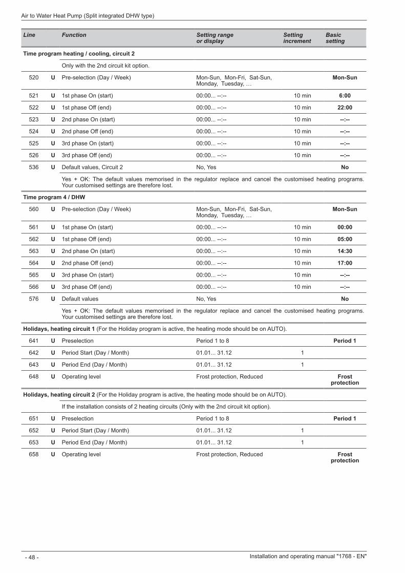
Line Function Setting range or display
Setting increment
Basic setting
Time program heating / cooling, circuit 2
Only with the 2nd circuit kit option.
520 U Pre-selection (Day / Week) Mon-Sun, Mon-Fri, Sat-Sun, Monday, Tuesday, …
Mon-Sun
521 U 1st phase On (start) 00:00... --:-- 10 min 6:00
522 U 1st phase Off (end) 00:00... --:-- 10 min 22:00
523 U 2nd phase On (start) 00:00... --:-- 10 min --:--
524 U 2nd phase Off (end) 00:00... --:-- 10 min --:--
525 U 3rd phase On (start) 00:00... --:-- 10 min --:--
526 U 3rd phase Off (end) 00:00... --:-- 10 min --:--
536 U Default values, Circuit 2 No, Yes No
Yes + OK: The default values memorised in the regulator replace and cancel the customised heating programs. Your customised settings are therefore lost.
Time program 4 / DHW
560 U Pre-selection (Day / Week) Mon-Sun, Mon-Fri, Sat-Sun, Monday, Tuesday, …
Mon-Sun
561 U 1st phase On (start) 00:00... --:-- 10 min 00:00
562 U 1st phase Off (end) 00:00... --:-- 10 min 05:00
563 U 2nd phase On (start) 00:00... --:-- 10 min 14:30
564 U 2nd phase Off (end) 00:00... --:-- 10 min 17:00
565 U 3rd phase On (start) 00:00... --:-- 10 min --:--
566 U 3rd phase Off (end) 00:00... --:-- 10 min --:--
576 U Default values No, Yes No
Yes + OK: The default values memorised in the regulator replace and cancel the customised heating programs. Your customised settings are therefore lost.
Holidays, heating circuit 1 (For the Holiday program is active, the heating mode should be on AUTO).
641 U Preselection Period 1 to 8 Period 1
642 U Period Start (Day / Month) 01 01 31 12 1
643 U Period End (Day / Month) 01 01 31 12 1
648 U Operating level Frost protection, Reduced Frost protection
Holidays, heating circuit 2 (For the Holiday program is active, the heating mode should be on AUTO).
If the installation consists of 2 heating circuits (Only with the 2nd circuit kit option).
651 U Preselection Period 1 to 8 Period 1
652 U Period Start (Day / Month) 01 01 31 12 1
653 U Period End (Day / Month) 01 01 31 12 1
658 U Operating level Frost protection, Reduced Frost protection
Installation and operating manual "1768 - EN"
Air to Water Heat Pump (Split integrated DHW type)
- 48 -
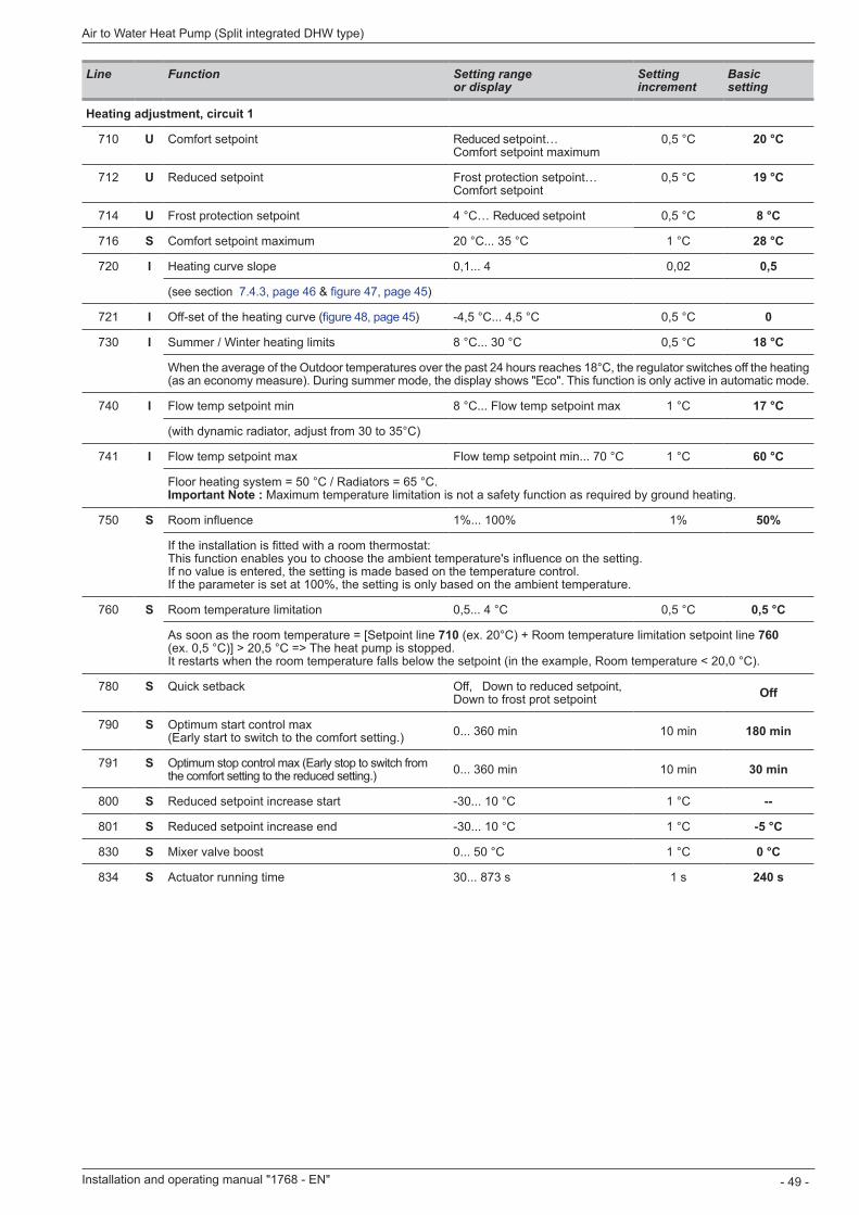
Line Function Setting range or display
Setting increment
Basic setting
Heating adjustment, circuit 1
710 U Comfort setpoint Reduced setpoint… Comfort setpoint maximum
0,5 °C 20 °C
712 U Reduced setpoint Frost protection setpoint… Comfort setpoint
0,5 °C 19 °C
714 U Frost protection setpoint 4 °C… Reduced setpoint 0,5 °C 8 °C
716 S Comfort setpoint maximum 20 °C 35 °C 1 °C 28 °C
720 I Heating curve slope 0,1... 4 0,02 0,5
(see section 7.4.3, page 46 & figure 47, page 45)
721 I Off-set of the heating curve (figure 48, page 45) -4,5 °C... 4,5 °C 0,5 °C 0
730 I Summer / Winter heating limits 8 °C 30 °C 0,5 °C 18 °C
When the average of the Outdoor temperatures over the past 24 hours reaches 18°C, the regulator switches off the heating (as an economy measure). During summer mode, the display shows "Eco". This function is only active in automatic mode.
740 I Flow temp setpoint min 8 °C... Flow temp setpoint max 1 °C 17 °C
(with dynamic radiator, adjust from 30 to 35°C)
741 I Flow temp setpoint max Flow temp setpoint min... 70 °C 1 °C 60 °C
Floor heating system = 50 °C / Radiators = 65 °C. Important Note : Maximum temperature limitation is not a safety function as required by ground heating.
750 S Room influence 1%... 100% 1% 50%
If the installation is fitted with a room thermostat: This function enables you to choose the ambient temperature's influence on the setting. If no value is entered, the setting is made based on the temperature control. If the parameter is set at 100%, the setting is only based on the ambient temperature.
760 S Room temperature limitation 0,5... 4 °C 0,5 °C 0,5 °C
As soon as the room temperature = [Setpoint line 710 (ex. 20°C) + Room temperature limitation setpoint line 760 (ex. 0,5 °C)] > 20,5 °C => The heat pump is stopped. It restarts when the room temperature falls below the setpoint (in the example, Room temperature < 20,0 °C).
780 S Quick setback Off, Down to reduced setpoint, Down to frost prot setpoint Off
790 S Optimum start control max (Early start to switch to the comfort setting.) 0... 360 min 10 min 180 min
791 S Optimum stop control max (Early stop to switch from the comfort setting to the reduced setting.) 0... 360 min 10 min 30 min
800 S Reduced setpoint increase start -30... 10 °C 1 °C --
801 S Reduced setpoint increase end -30... 10 °C 1 °C -5 °C
830 S Mixer valve boost 0 50 °C 1 °C 0 °C
834 S Actuator running time 30... 873 s 1 s 240 s
Installation and operating manual "1768 - EN" - 49 -
Air to Water Heat Pump (Split integrated DHW type)

Line Function Setting range or display
Setting increment
Basic setting
850 I Floor curing function (figure 50) Off
- Off: Early interruption of the current programme, programme inactive. - Operational heating. - Heating ready for occupation. - Operational heating + ready heating. - Ready heating + operational heating. - Manual: Manual mode enables you to programme your own concrete slab drying time.The function ends automatically after 25 days.
" Please comply with the standards and instructions of the manufacturer of the building ! A good performance of this function is only possible with an installation correctly implemented (hydraulic, electricity and adjustments) ! This function can be stopped by anticipation when setting the adjustment on "Off" .
5045403530
2050
25
55
1 15 7
X
10 18
25
15
1
figure 50 - Diagram of the concrete slab drying programmes
Hea
ting
flow
tem
pera
ture
°C
Operational heating + Heating ready for occupation
Heating ready for occupation
Day
Operational heating
851 I Floor curing setpoint manually (if line 850 = manual)
0 95 °C 1 °C 25 °C
This function enables you to set the custom concrete slab drying temperature. This temperature remains fixed. The concrete slab-drying programme stops automatically after running for 25 days.
856 I Floor curing day current 0 32
857 I Floor curing day completed 0 32
900 S Operating mode changeover None, Protection mode, Reduced, Comfort, Automatic
1 Reduced
Operating mode at end of concrete slab drying period
Cooling circuit 1
If the installation is fitted with the cooling kit (Only with the cooling kit option).
901 U Operating mode Protection, Automatic, Reduced, Comfort
Protection
902 U Comfort cooling setpoint 17 40 °C 0,5 °C 24 °C
903 U Reduced setpoint 5 40°C 26 °C
908 I Flow temp setp at OT° 25°C 6 35 °C 0,5 °C 20 °C
909 I Flow temp setp at OT° 35°C 6 35 °C 0,5 °C 16 °C
912 I Cooling limit at OT° 8 35 °C 0,5 °C 24 °C
913 S Lock time at end of heating / cooling 8 100 1 h 24 h
918 S Summer comp start at OT° 20 50 °C 1 °C 26 °C
919 S Summer comp end at OT° 20 50 °C 1 °C 40 °C
920 S Summer comp setp increase 1 10 °C 1 °C 4 °C
923 S Flow temp setp min OT° 25°C 6 35 °C 0,5 °C 18 °C
924 S Flow temp setp min OT° 35°C 6 35 °C 0,5 °C 18 °C
Installation and operating manual "1768 - EN"
Air to Water Heat Pump (Split integrated DHW type)
- 50 -
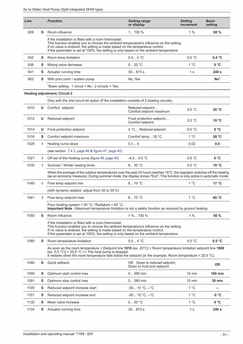
Line Function Setting range or display
Setting increment
Basic setting
928 S Room influence 1... 100 % 1 % 80 %
If the installation is fitted with a room thermostat: This function enables you to choose the ambient temperature's influence on the setting. If no value is entered, the setting is made based on the temperature control. If the parameter is set at 100%, the setting is only based on the ambient temperature.
932 S Room temp limitation 0,5... 4 °C 0,5 °C 0,5 °C
938 S Mixing valve decrease 0 20 °C 1 °C 0 °C
941 S Actuator running time 30... 873 s 1 s 240 s
963 S With prim contr / system pump No, Yes No*
*Basic setting : 1 circuit = No ; 2 circuits = Yes.
Heating adjustment, Circuit 2
Only with the 2nd circuit kit option (If the installation consists of 2 heating circuits).
1010 U Comfort setpoint Reduced setpoint… Comfort setpoint maximum 0,5 °C 20 °C
1012 U Reduced setpoint Frost protection setpoint… Comfort setpoint 0,5 °C 19 °C
1014 U Frost protection setpoint 4 °C… Reduced setpoint 0,5 °C 8 °C
1016 S Comfort setpoint maximum Comfort temp... 35 °C 1 °C 28 °C
1020 I Heating curve slope 0,1... 4 0,02 0,5
(see section 7.4.3, page 46 & figure 47, page 45)
1021 I Off-set of the heating curve (figure 48, page 45) -4,5... 4,5 °C 0,5 °C 0 °C
1030 I Summer / Winter heating limits 8 30 °C 0,5 °C 18 °C
When the average of the outdoor temperatures over the past 24 hours reaches 18°C, the regulator switches off the heating (as an economy measure). During summer mode, the display shows "Eco". This function is only active in automatic mode.
1040 I Flow temp setpoint min 8 70 °C 1 °C 17 °C
(with dynamic radiator, adjust from 30 to 35°C)
1041 I Flow temp setpoint max 8 70 °C 1 °C 60 °C
Floor heating system = 50 °C / Radiators = 65 °C. Important Note : Maximum temperature limitation is not a safety function as required by ground heating.
1050 S Room influence 1 %... 100 % 1 % 50 %
If the installation is fitted with a room thermostat: This function enables you to choose the ambient temperature's influence on the setting. If no value is entered, the setting is made based on the temperature control. If the parameter is set at 100%, the setting is only based on the ambient temperature.
1060 S Room temperature limitation 0,5... 4 °C 0 5 °C 0.5 °C
As soon as the room temperature = [Setpoint line 1010 (ex. 20°C) + Room temperature limitation setpoint line 1060 (ex. 0,5 °C)] > 20,5 °C => The heat pump is stopped. It restarts when the room temperature falls below the setpoint (in the example, Room temperature < 20,0 °C).
1080 S Quick setback Off, Down to reduced setpoint, Down to frost prot setpoint Off
1090 S Optimum start control max 0... 360 min 10 min 180 min
1091 S Optimum stop control max 0... 360 min 10 min 30 min
1100 S Reduced setpoint increase start -30... 10 °C, --°C 1 °C --
1101 S Reduced setpoint increase end -30... 10 °C, --°C 1 °C -5 °C
1130 S Mixer valve increase 0 50 °C 1 °C 0 °C
1134 S Actuator running time 30... 873 s 1 s 240 s
Installation and operating manual "1768 - EN" - 51 -
Air to Water Heat Pump (Split integrated DHW type)
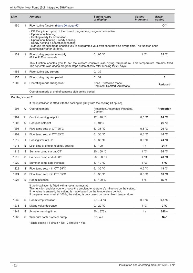
Line Function Setting range or display
Setting increment
Basic setting
1150 I Floor curing function (figure 50, page 50) Off
- Off: Early interruption of the current programme, programme inactive. - Operational heating. - Heating ready for occupation. - Operational heating + ready heating. - Ready heating + operational heating. - Manual: Manual mode enables you to programme your own concrete slab drying time.The function ends automatically after 25 days.
1151 I Floor curing setpoint manually (if line 1150 = manual)
0 95 °C 1 °C 25 °C
This function enables you to set the custom concrete slab drying temperature. This temperature remains fixed. The concrete slab-drying program stops automatically after running for 25 days.
1156 I Floor curing day current 0 32
1157 I Floor curing day completed 0 32 0
1200 S Operating mode changeover None, Protection mode, Reduced, Comfort, Automatic Reduced
Operating mode at end of concrete slab drying period.
Cooling circuit 2
If the installation is fitted with the cooling kit (Only with the cooling kit option).
1201 U Operating mode Protection, Automatic, Reduced, Comfort
Protection
1202 U Comfort cooling setpoint 17 40 °C 0,5 °C 24 °C
1203 U Reduced setpoint 5 40°C 26 °C
1208 I Flow temp setp at OT° 25°C 6 35 °C 0,5 °C 20 °C
1209 I Flow temp setp at OT° 35°C 6 35 °C 0,5 °C 16 °C
1212 I Cooling limit at OT° 8 35 °C 0,5 °C 24 °C
1213 S Lock time at end of heating / cooling 8 100 1 h 24 h
1218 S Summer comp start at OT° 20 50 °C 1 °C 26 °C
1219 S Summer comp end at OT° 20 50 °C 1 °C 40 °C
1220 S Summer comp setp increase 1 10 °C 1 °C 4 °C
1223 S Flow temp setp min OT° 25°C 6 35 °C 0,5 °C 18 °C
1224 S Flow temp setp min OT° 35°C 6 35 °C 0,5 °C 18 °C
1228 S Room influence 1... 100 % 1 % 80 %
If the installation is fitted with a room thermostat: This function enables you to choose the ambient temperature's influence on the setting. If no value is entered, the setting is made based on the temperature control. If the parameter is set at 100%, the setting is only based on the ambient temperature.
1232 S Room temp limitation 0,5... 4 °C 0,5 °C 0,5 °C
1238 S Mixing valve decrease 0 20 °C 1 °C 0 °C
1241 S Actuator running time 30... 873 s 1 s 240 s
1263 S With prim contr / system pump No, Yes No*
*Basic setting : 1 circuit = No ; 2 circuits = Yes.
Installation and operating manual "1768 - EN"
Air to Water Heat Pump (Split integrated DHW type)
- 52 -
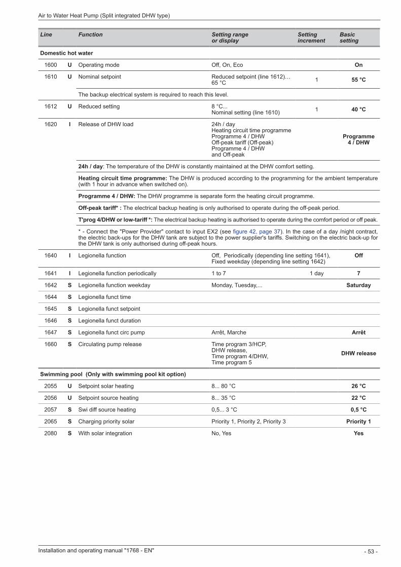
Line Function Setting range or display
Setting increment
Basic setting
Domestic hot water
1600 U Operating mode Off, On, Eco On
1610 U Nominal setpoint Reduced setpoint (line 1612)… 65 °C 1 55 °C
The backup electrical system is required to reach this level.
1612 U Reduced setting 8 °C Nominal setting (line 1610) 1 40 °C
1620 I Release of DHW load 24h / day Heating circuit time programme Programme 4 / DHW Off-peak tariff (Off-peak) Programme 4 / DHW and Off-peak
Programme 4 / DHW
24h / day: The temperature of the DHW is constantly maintained at the DHW comfort setting.
Heating circuit time programme: The DHW is produced according to the programming for the ambient temperature (with 1 hour in advance when switched on).
Programme 4 / DHW: The DHW programme is separate form the heating circuit programme.
Off-peak tariff* : The electrical backup heating is only authorised to operate during the off-peak period.
T'prog 4/DHW or low-tariff *: The electrical backup heating is authorised to operate during the comfort period or off peak.
* - Connect the "Power Provider" contact to input EX2 (see figure 42, page 37). In the case of a day /night contract, the electric back-ups for the DHW tank are subject to the power supplier's tariffs. Switching on the electric back-up for the DHW tank is only authorised during off-peak hours.
1640 I Legionella function Off, Periodically (depending line setting 1641), Fixed weekday (depending line setting 1642)
Off
1641 I Legionella function periodically 1 to 7 1 day 7
1642 S Legionella function weekday Monday, Tuesday,... Saturday
1644 S Legionella funct time
1645 S Legionella funct setpoint
1646 S Legionella funct duration
1647 S Legionella funct circ pump Arrêt, Marche Arrêt
1660 S Circulating pump release Time program 3/HCP, DHW release, Time program 4/DHW, Time program 5
DHW release
Swimming pool (Only with swimming pool kit option)
2055 U Setpoint solar heating 8 80 °C 26 °C
2056 U Setpoint source heating 8 35 °C 22 °C
2057 S Swi diff source heating 0,5... 3 °C 0,5 °C
2065 S Charging priority solar Priority 1, Priority 2, Priority 3 Priority 1
2080 S With solar integration No, Yes Yes
Installation and operating manual "1768 - EN" - 53 -
Air to Water Heat Pump (Split integrated DHW type)
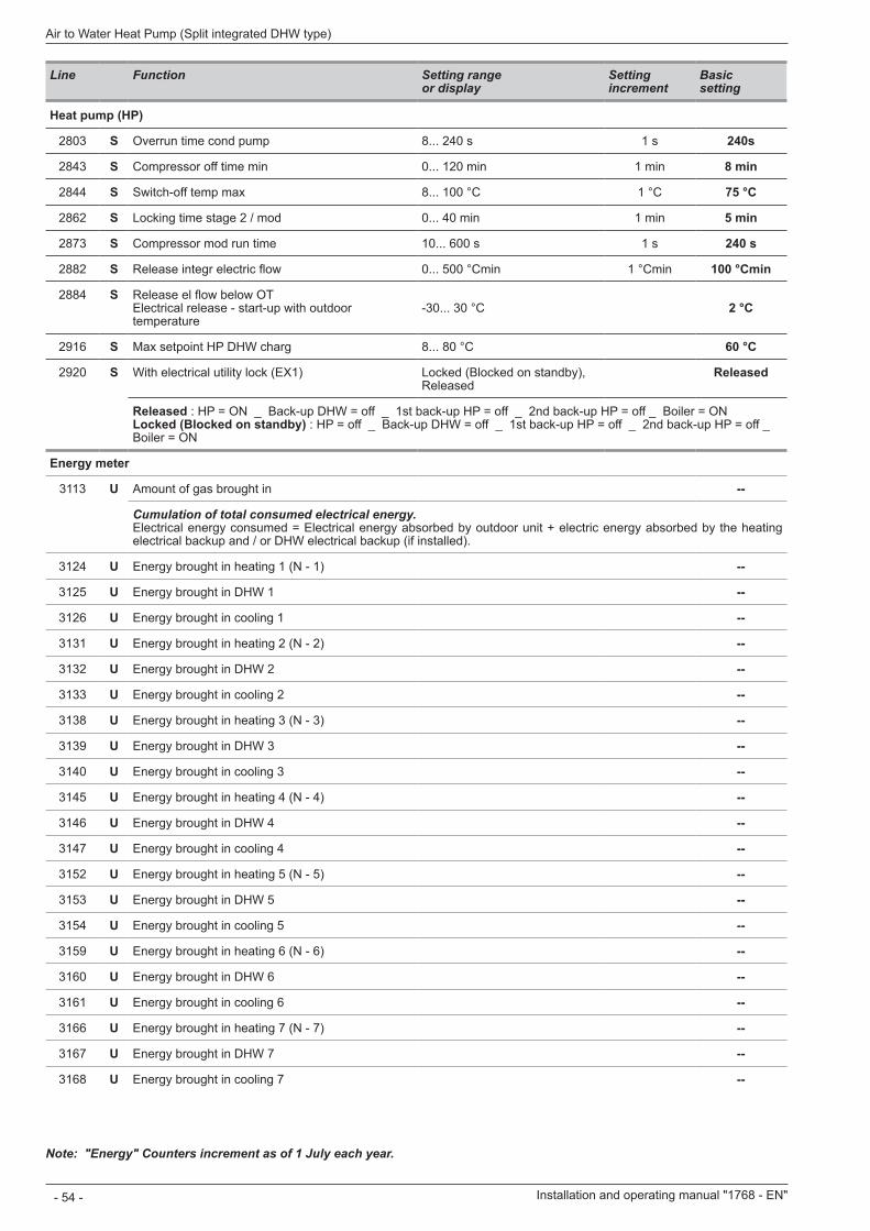
Line Function Setting range or display
Setting increment
Basic setting
Heat pump (HP)
2803 S Overrun time cond pump 8... 240 s 1 s 240s
2843 S Compressor off time min 0... 120 min 1 min 8 min
2844 S Switch-off temp max 8 100 °C 1 °C 75 °C
2862 S Locking time stage 2 / mod 0... 40 min 1 min 5 min
2873 S Compressor mod run time 10... 600 s 1 s 240 s
2882 S Release integr electric flow 0... 500 °Cmin 1 °Cmin 100 °Cmin
2884 S Release el flow below OT Electrical release - start-up with outdoor temperature
-30... 30 °C 2 °C
2916 S Max setpoint HP DHW charg 8 80 °C 60 °C
2920 S With electrical utility lock (EX1) Locked (Blocked on standby), Released
Released
Released : HP = ON _ Back-up DHW = off _ 1st back-up HP = off _ 2nd back-up HP = off _ Boiler = ON Locked (Blocked on standby) : HP = off _ Back-up DHW = off _ 1st back-up HP = off _ 2nd back-up HP = off _ Boiler = ON
Energy meter
3113 U Amount of gas brought in --
Cumulation of total consumed electrical energy.Electrical energy consumed = Electrical energy absorbed by outdoor unit + electric energy absorbed by the heating electrical backup and / or DHW electrical backup (if installed).
3124 U Energy brought in heating 1 (N - 1) --
3125 U Energy brought in DHW 1 --
3126 U Energy brought in cooling 1 --
3131 U Energy brought in heating 2 (N - 2) --
3132 U Energy brought in DHW 2 --
3133 U Energy brought in cooling 2 --
3138 U Energy brought in heating 3 (N - 3) --
3139 U Energy brought in DHW 3 --
3140 U Energy brought in cooling 3 --
3145 U Energy brought in heating 4 (N - 4) --
3146 U Energy brought in DHW 4 --
3147 U Energy brought in cooling 4 --
3152 U Energy brought in heating 5 (N - 5) --
3153 U Energy brought in DHW 5 --
3154 U Energy brought in cooling 5 --
3159 U Energy brought in heating 6 (N - 6) --
3160 U Energy brought in DHW 6 --
3161 U Energy brought in cooling 6 --
3166 U Energy brought in heating 7 (N - 7) --
3167 U Energy brought in DHW 7 --
3168 U Energy brought in cooling 7 --
Note: "Energy" Counters increment as of 1 July each year.
Installation and operating manual "1768 - EN"
Air to Water Heat Pump (Split integrated DHW type)
- 54 -
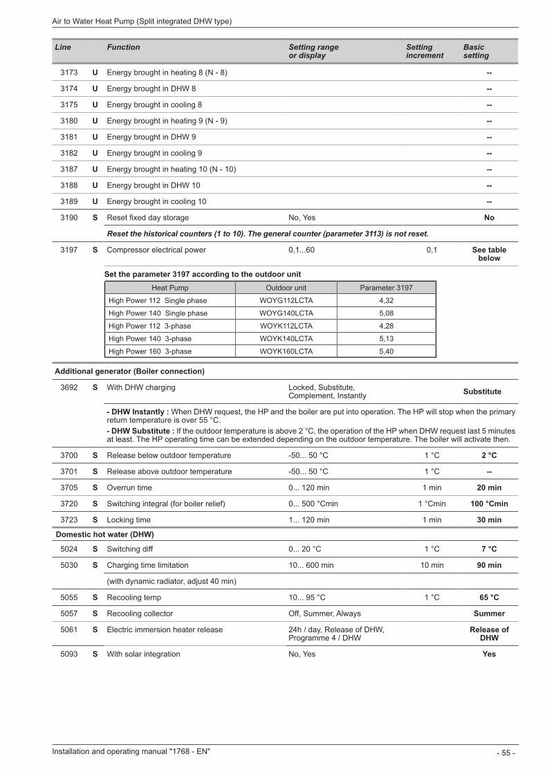
Line Function Setting range or display
Setting increment
Basic setting
3173 U Energy brought in heating 8 (N - 8) --
3174 U Energy brought in DHW 8 --
3175 U Energy brought in cooling 8 --
3180 U Energy brought in heating 9 (N - 9) --
3181 U Energy brought in DHW 9 --
3182 U Energy brought in cooling 9 --
3187 U Energy brought in heating 10 (N - 10) --
3188 U Energy brought in DHW 10 --
3189 U Energy brought in cooling 10 --
3190 S Reset fixed day storage No, Yes No
Reset the historical counters (1 to 10). The general counter (parameter 3113) is not reset.
3197 S Compressor electrical power 0,1...60 0,1 See tablebelow
Set the parameter 3197 according to the outdoor unitHeat Pump Outdoor unit Parameter 3197
excellia (duo) 11 Single phase WOYG112LCT(A) 4,32
excellia (duo) 14 Single phase WOYG140LCT(A) 5,08
excellia (duo) 11 3-phase WOYK112LCT(A) 4,28
excellia (duo) 14 3-phase WOYK140LCT(A) 5,13
excellia (duo) 16 3-phase WOYK160LCT(A) 5,40
Additional generator (Boiler connection)
3692 S With DHW charging Locked, Substitute, Complement, Instantly Substitute
- DHW Instantly : When DHW request, the HP and the boiler are put into operation. The HP will stop when the primary return temperature is over 55 °C.- DHW Substitute : If the outdoor temperature is above 2 °C, the operation of the HP when DHW request last 5 minutes at least. The HP operating time can be extended depending on the outdoor temperature. The boiler will activate then.
3700 S Release below outdoor temperature -50... 50 °C 1 °C 2 °C
3701 S Release above outdoor temperature -50... 50 °C 1 °C --
3705 S Overrun time 0... 120 min 1 min 20 min
3720 S Switching integral (for boiler relief) 0... 500 °Cmin 1 °Cmin 100 °Cmin
3723 S Locking time 1... 120 min 1 min 30 min
Domestic hot water (DHW)
5024 S Switching diff 0 20 °C 1 °C 7 °C
5030 S Charging time limitation 10... 600 min 10 min 90 min
(with dynamic radiator, adjust 40 min)
5055 S Recooling temp 10 95 °C 1 °C 65 °C
5057 S Recooling collector Off, Summer, Always Summer
5061 S Electric immersion heater release 24h / day, Release of DHW, Programme 4 / DHW
Release of DHW
5093 S With solar integration No, Yes Yes
Installation and operating manual "1768 - EN" - 55 -
Air to Water Heat Pump (Split integrated DHW type)
Heat Pump Outdoor unit Parameter 3197
High Power 112 Single phase WOYG112LCTA 4,32
High Power 140 Single phase WOYG140LCTA 5,08
High Power 112 3-phase WOYK112LCTA 4,28
High Power 140 3-phase WOYK140LCTA 5,13
High Power 160 3-phase WOYK160LCTA 5,40
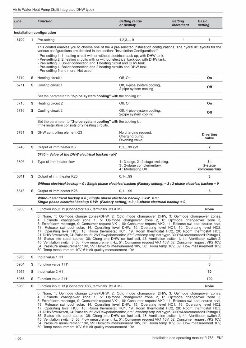
Line Function Setting range or display
Setting increment
Basic setting
Installation configuration
5700 I Pre-setting 1,2,3,... 9 1 1
This control enables you to choose one of the 4 pre-selected installation configurations. The hydraulic layouts for the various configurations are detailed in the section: "Installation Configurations".- Pre-setting 1: 1 heating circuit with or without electrical back-up, with DHW tank. - Pre-setting 2: 2 heating circuits with or without electrical back-up, with DHW tank. - Pre-setting 3: Boiler connection and 1 heating circuit and DHW tank. - Pre-setting 4: Boiler connection and 2 heating circuits and DHW tank. - Pre-setting 5 and more: Not used.
5710 S Heating circuit 1 Off, On On
5711 S Cooling circuit 1 Off, 4-pipe system cooling, 2-pipe system cooling Off
Set the parameter to "2-pipe system cooling" with the cooling kit.
5715 S Heating circuit 2 Off, On On
5716 S Cooling circuit 2 Off, 4-pipe system cooling, 2-pipe system cooling Off
Set the parameter to "2-pipe system cooling" with the cooling kit. If the installation consists of 2 heating circuits.
5731 S DHW controlling element Q3 No charging request, Charging pump, Diverting valve
Diverting valve
5740 S Output el imm heater K6 0,1... 99 kW 2
5740 = Value of the DHW electrical backup - kW
5806 I Type el imm heater flow 1 : 3-stage, 2 : 2-stage excluding, 3 : 2-stage complementary, 4 : Modulating UX
3 : 2-stage
complementary
5811 S Output el imm heater K25 0,1-...99 3
Without electrical backup = 0 ; Single phase electrical backup (Factory setting) = 3 ; 3-phase electrical backup = 9
5813 S Output el imm heater K26 0,1-...99 3
Without electrical backup = 0 ; Single phase electrical backup 3 kW = 0 ; Single phase electrical backup 6 kW (Factory setting) = 3 ; 3-phase electrical backup = 0
5950 S Function input H1 (Connector X86, terminals B1 & M) None
0: None, 1: Op'mode change zones+DHW, 2: Optg mode changeover DHW, 3: Op'mode changeover zones, 4: Op'mode changeover zone 1, 5: Op'mode changeover zone 2, 6: Op'mode changeover zone 3, 8: Error/alarm message, 9: Consumer request VK1, 10: Consumer request VK2, 11: Release swi pool source heat, 13: Release swi pool solar, 14: Operating level DHW, 15: Operating level HC1, 16: Operating level HC2, 17: Operating level HC3, 18: Room thermostat HC1, 19: Room thermostat HC2, 20: Room thermostat HC3, 21: DHW flow switch, 24: Pulse count, 26: Dewpoint monitor, 27: Flow temp setp incr hygro, 30: Swi-on command HP stage 1, 35: Status info suppl source, 36: Charg prio DHW sol fuel boil, 43: Ventilation switch 1, 44: Ventilation switch 2, 45: Ventilation switch 3, 50: Flow measurement Hz, 51: Consumer request VK1 10V, 52: Consumer request VK2 10V, 54: Pressure measurement 10V, 55: Humidity measurement 10V, 56: Room temp 10V, 59: Flow measurement 10V, 60: Temp measurement 10V, 61: Air quality measurement 10V
5953 S Input value 1 H1 0
5954 S Function value 1 H1 0
5955 S Input value 2 H1 10
5956 S Function value 2 H1 100
5960 S Function input H3 (Connector X86, terminals B2 & M) None
0: None, 1: Op'mode change zones+DHW, 2: Optg mode changeover DHW, 3: Op'mode changeover zones, 4: Op'mode changeover zone 1, 5: Op'mode changeover zone 2, 6: Op'mode changeover zone 3, 8: Error/alarm message, 9: Consumer request VK1, 10: Consumer request VK2, 11: Release swi pool source heat, 13: Release swi pool solar, 14: Operating level DHW, 15: Operating level HC1, 16: Operating level HC2, 17: Operating level HC3, 18: Room thermostat HC1, 19: Room thermostat HC2, 20: Room thermostat HC3, 21: DHW flow switch, 24: Pulse count, 26: Dewpoint monitor, 27: Flow temp setp incr hygro, 30: Swi-on command HP stage 1, 35: Status info suppl source, 36: Charg prio DHW sol fuel boil, 43: Ventilation switch 1, 44: Ventilation switch 2, 45: Ventilation switch 3, 50: Flow measurement Hz, 51: Consumer request VK1 10V, 52: Consumer request VK2 10V, 54: Pressure measurement 10V, 55: Humidity measurement 10V, 56: Room temp 10V, 59: Flow measurement 10V, 60: Temp measurement 10V, 61: Air quality measurement 10V
Installation and operating manual "1768 - EN"
Air to Water Heat Pump (Split integrated DHW type)
- 56 -
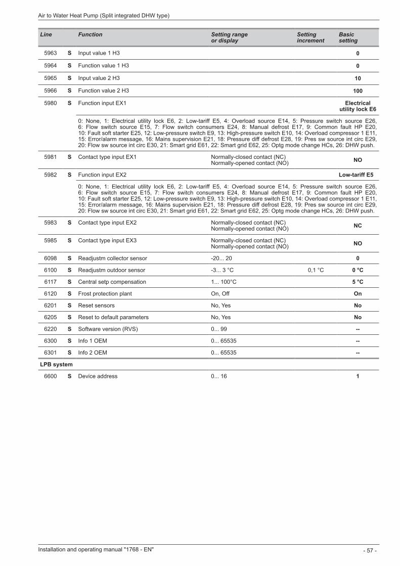
Line Function Setting range or display
Setting increment
Basic setting
5963 S Input value 1 H3 0
5964 S Function value 1 H3 0
5965 S Input value 2 H3 10
5966 S Function value 2 H3 100
5980 S Function input EX1 Electrical utility lock E6
0: None, 1: Electrical utility lock E6, 2: Low-tariff E5, 4: Overload source E14, 5: Pressure switch source E26, 6: Flow switch source E15, 7: Flow switch consumers E24, 8: Manual defrost E17, 9: Common fault HP E20, 10: Fault soft starter E25, 12: Low-pressure switch E9, 13: High-pressure switch E10, 14: Overload compressor 1 E11, 15: Error/alarm message, 16: Mains supervision E21, 18: Pressure diff defrost E28, 19: Pres sw source int circ E29, 20: Flow sw source int circ E30, 21: Smart grid E61, 22: Smart grid E62, 25: Optg mode change HCs, 26: DHW push.
5981 S Contact type input EX1 Normally-closed contact (NC) Normally-opened contact (NO) NO
5982 S Function input EX2 Low-tariff E5
0: None, 1: Electrical utility lock E6, 2: Low-tariff E5, 4: Overload source E14, 5: Pressure switch source E26, 6: Flow switch source E15, 7: Flow switch consumers E24, 8: Manual defrost E17, 9: Common fault HP E20, 10: Fault soft starter E25, 12: Low-pressure switch E9, 13: High-pressure switch E10, 14: Overload compressor 1 E11, 15: Error/alarm message, 16: Mains supervision E21, 18: Pressure diff defrost E28, 19: Pres sw source int circ E29, 20: Flow sw source int circ E30, 21: Smart grid E61, 22: Smart grid E62, 25: Optg mode change HCs, 26: DHW push.
5983 S Contact type input EX2 Normally-closed contact (NC) Normally-opened contact (NO) NC
5985 S Contact type input EX3 Normally-closed contact (NC) Normally-opened contact (NO) NO
6098 S Readjustm collector sensor -20... 20 0
6100 S Readjustm outdoor sensor -3... 3 °C 0,1 °C 0 °C
6117 S Central setp compensation 1 100°C 5 °C
6120 S Frost protection plant On, Off On
6201 S Reset sensors No, Yes No
6205 S Reset to default parameters No, Yes No
6220 S Software version (RVS) 0 99 --
6300 S Info 1 OEM 0 65535 --
6301 S Info 2 OEM 0 65535 --
LPB system
6600 S Device address 0 16 1
Installation and operating manual "1768 - EN" - 57 -
Air to Water Heat Pump (Split integrated DHW type)
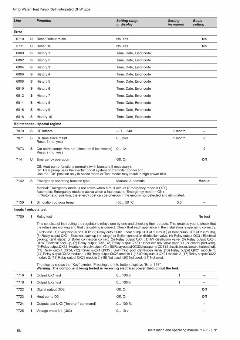
Line Function Setting range or display
Setting increment
Basic setting
Error
6710 U Reset Defaut relais No, Yes No
6711 U Reset HP No, Yes No
6800 S History 1 Time, Date, Error code
6802 S History 2 Time, Date, Error code
6804 S History 3 Time, Date, Error code
6806 S History 4 Time, Date, Error code
6808 S History 5 Time, Date, Error code
6810 S History 6 Time, Date, Error code
6812 S History 7 Time, Date, Error code
6814 S History 8 Time, Date, Error code
6816 S History 9 Time, Date, Error code
6818 S History 10 Time, Date, Error code
Maintenance / special regime
7070 S HP interval --, 1... 240 1 month --
7071 S HP time since maint Reset ? (no, yes)
0 240 1 month 0
7073 S Cur starts compr1/hrs run (since the 6 last weeks) Reset ? (no, yes)
0 12 0
7141 U Emergency operation Off, On Off
Off: Heat pump functions normally (with boosters if necessary). On: Heat pump uses the electric boost system or the boiler connection. Use the “On” position only in Assist mode or Test mode: may result in high power bills.
7142 S Emergency operating function type Manual, Automatic Manual
Manual: Emergency mode is not active when a fault occurs (Emergency mode = OFF). Automatic: Emergency mode is active when a fault occurs (Emergency mode = ON). In "Automatic" position, the energy cost can be onerous if the error is not detected and eliminated.
7150 I Simulation outdoor temp -50... 50 °C 0,5 --
Inputs / outputs test
7700 I Relay test No test
This consists of instructing the regulator's relays one by one and checking their outputs. This enables you to check that the relays are working and that the cabling is correct. Check that each appliance in the installation is operating correctly.(0) No test, (1) Everything is on STOP, (2) Relay output QX1 : heat pump CC1 (if 1 circuit ) or heat pump CC2 (if 2 circuits), (3) Relay output QX2 : Electrical back-up (1st stage) or Boiler connection distribution valve, (4) Relay output QX3 : Electrical back-up (2nd stage) or Boiler connection contact, (5) Relay output QX4 : DHW distribution valve, (6) Relay output QX5 : DHW Electrical back-up, (7) Relay output QX6 , (8) Relay output QX31 : Heat circ mix valve open Y1 (or control pilot-wire), (9) Relay output QX32 : Heat circ mix valve close Y2, (10) Relay output QX33 : heat pump CC1 if 2 circuits (mixed circuit, the less hot), (11) Relay output QX34, (12) Relay output QX35 : Swimming pool distribution valve, (13) Relay output QX21 module 1, (14) Relay output QX22 module 1, (15) Relay output QX23 module 1, (16) Relay output QX21 module 2, (17) Relay output QX22 module 2, (18) Relay output QX23 module 2, (19) Not used, (20) Not used, (21) Not used.
The display shows the “Key” symbol. Pressing the Info button displays "Error 368". Warning: The component being tested is receiving electrical power throughout the test.
7710 I Output UX1 test 0... 100% 1 --
7716 I Output UX2 test 0... 100% 1 --
7722 I Digital output DO2 Off, On Off
7723 I Heat pump D3 Off, On Off
7724 I Outputs test UX3 ("Inverter" command) 0... 100 % --
7725 I Voltage value U4 (Ux3) 0... 10 v --
Installation and operating manual "1768 - EN"
Air to Water Heat Pump (Split integrated DHW type)
- 58 -
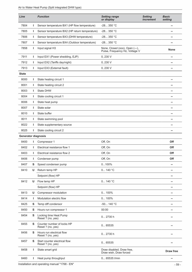
Line Function Setting range or display
Setting increment
Basic setting
7804 I Sensor temperature BX1 (HP flow temperature) -28... 350 °C --
7805 I Sensor temperature BX2 (HP return temperature) -28... 350 °C --
7806 I Sensor temperature BX3 (DHW temperature) -28... 350 °C --
7807 I Sensor temperature BX4 (Outdoor temperature) -28... 350 °C --
7858 I Input signal H3 None, Closed (ooo), Open (---), Pulse, Frequency Hz, Voltage V None
7911 I Input EX1 (Power shedding, EJP) 0, 230 V --
7912 I Input EX2 (Tariffs day/night) 0, 230 V --
7913 I Input EX3 (External fault) 0, 230 V --
State
8000 I State heating circuit 1 --
8001 I State heating circuit 2 --
8003 I State DHW --
8004 I State cooling circuit 1 --
8006 I State heat pump --
8007 I State solar --
8010 I State buffer --
8011 I State swimming pool --
8022 I State supplementary source --
8025 I State cooling circuit 2 --
Generator diagnosis
8400 I Compressor 1 Off, On Off
8402 I Electrical resistance flow 1 Off, On Off
8403 I Electrical resistance flow 2 Off, On Off
8406 I Condenser pump Off, On Off
8407 S Speed condenser pump 0...100% --
8410 U Return temp HP 0 140 °C --
Setpoint (flow) HP --
8412 U Flow temp HP 0 140 °C --
Setpoint (flow) HP --
8413 U Compressor modulation 0... 100% --
8414 I Modulation electric flow 0... 100% --
8425 S Temp diff condensor -50... 140 °C --
8450 S Hours run compressor 1 00:00 --
8454 S Locking time Heat Pump Reset ? (no, yes) 0... 2730 h --
8455 S Counter number of locks HP Reset ? (no, yes) 0 65535 --
8456 S Hours run electrical flow Reset ? (no, yes) 0... 2730 h --
8457 S Start counter electrical flow Reset ? (no, yes) 0 65535 --
8458 I State smart grid Draw disabled, Draw free, Draw wish, Draw forced Draw free
8460 I Heat pump throughput 0... 65535 l/min --
Installation and operating manual "1768 - EN" - 59 -
Air to Water Heat Pump (Split integrated DHW type)
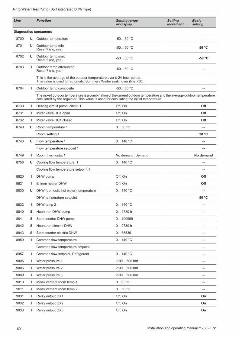
Line Function Setting range or display
Setting increment
Basic setting
Diagnostics consumers
8700 U Outdoor temperature -50... 50 °C --
8701 U Outdoor temp min Reset ? (no, yes) -50... 50 °C 50 °C
8702 U Outdoor temp max Reset ? (no, yes) -50... 50 °C -50 °C
8703 I Outdoor temp attenuated Reset ? (no, yes) -50... 50 °C --
This is the average of the outdoor temperature over a 24-hour period. This value is used for automatic Summer / Winter switchover (line 730).
8704 I Outdoor temp composite -50... 50 °C --
The mixed outdoor temperature is a combination of the current outdoor temperature and the average outdoor temperature calculated by the regulator. This value is used for calculating the initial temperature.
8730 I Heating circuit pump, circuit 1 Off, On Off
8731 I Mixer valve HC1 open Off, On Off
8732 I Mixer valve HC1 closed Off, On Off
8740 U Room temperature 1 0 50 °C --
Room setting 1 20 °C
8743 U Flow temperature 1 0 140 °C --
Flow temperature setpoint 1 --
8749 I Room thermostat 1 No demand, Demand No demand
8756 U Cooling flow temperature 1 0 140 °C --
Cooling flow temperature setpoint 1 --
8820 I DHW pump Off, On Off
8821 I El imm heater DHW Off, On Off
8830 U DHW (domestic hot water) temperature 0 140 °C --
DHW temperature setpoint 50 °C
8832 I DHW temp 2 0 140 °C --
8840 S Hours run DHW pump 0... 2730 h --
8841 S Start counter DHW pump 0 199999 --
8842 S Hours run electric DHW 0... 2730 h --
8843 S Start counter electric DHW 0 65535 --
8950 I Common flow temperature 0 140 °C --
Common flow temperature setpoint --
8957 I Common flow setpoint, Refrigerant 0 140 °C --
9005 I Water pressure 1 -100... 500 bar --
9006 I Water pressure 2 -100... 500 bar --
9009 I Water pressure 3 -100... 500 bar --
9010 I Measurement room temp 1 0 50 °C --
9011 I Measurement room temp 2 0 50 °C --
9031 I Relay output QX1 Off, On On
9032 I Relay output QX2 Off, On On
9033 I Relay output QX3 Off, On On
Installation and operating manual "1768 - EN"
Air to Water Heat Pump (Split integrated DHW type)
- 60 -
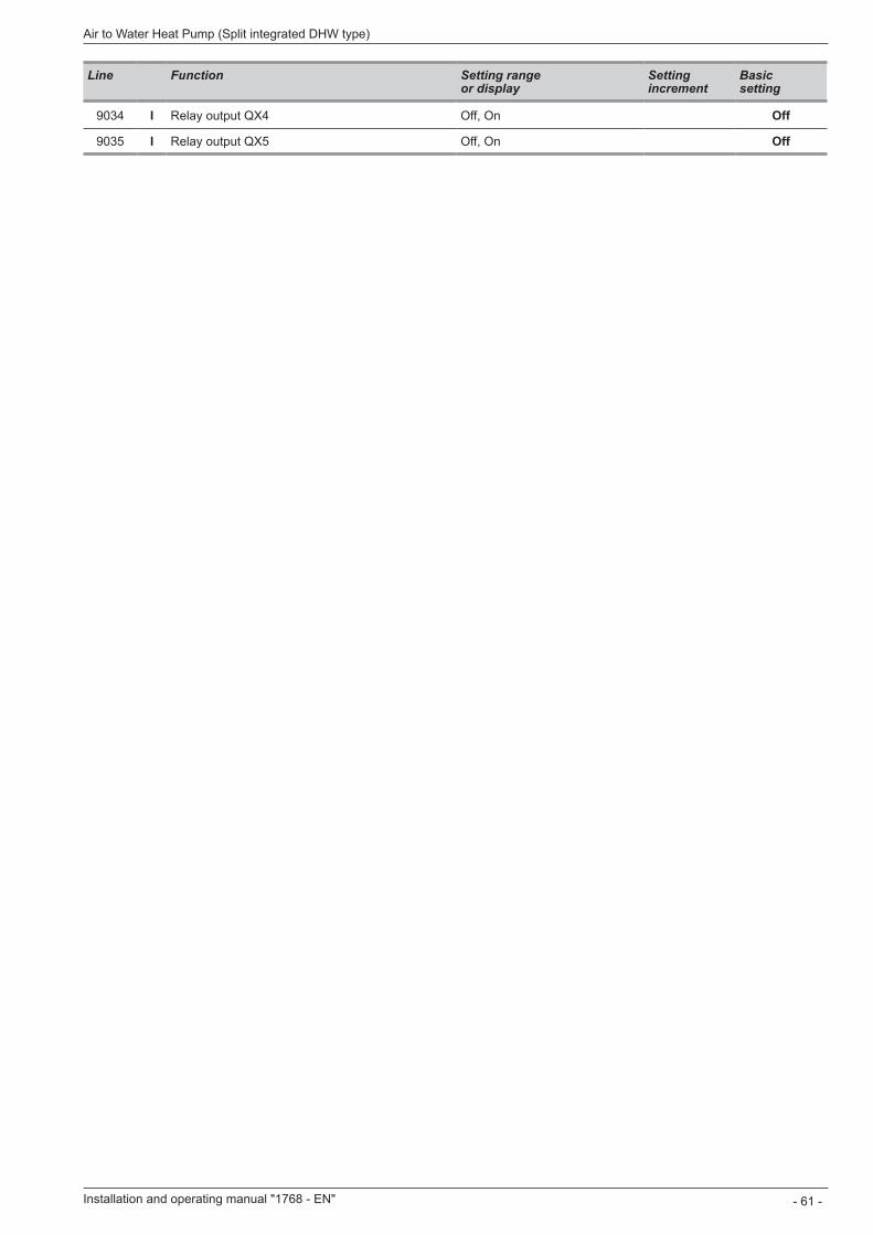
Line Function Setting range or display
Setting increment
Basic setting
9034 I Relay output QX4 Off, On Off
9035 I Relay output QX5 Off, On Off
Installation and operating manual "1768 - EN" - 61 -
Air to Water Heat Pump (Split integrated DHW type)
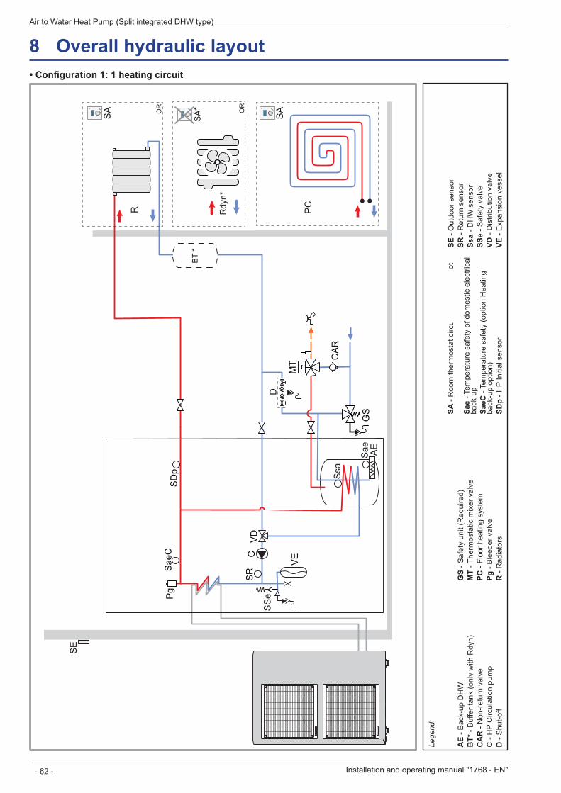
8 Overall hydraulic layout• Configuration 1: 1 heating circuit
SE
Ssa
Sae AE
SR
VEC
VD
GS
MT C
AR
SD
pP
gS
aeC
SS
eD
R
OU
PC
SA
SA
Rdy
n*
OU
SA
*B
T *
Lege
nd:
AE
- Bac
k-up
DH
WB
T* -
Buf
fer t
ank
(onl
y w
ith R
dyn)
C
AR
- N
on-r
etur
n va
lve
C -
HP
Circ
ulat
ion
pum
pD
- S
hut-o
ff
GS
- Saf
ety
unit
(Req
uire
d)M
T - T
herm
osta
tic m
ixer
val
vePC
- Fl
oor h
eatin
g sy
stem
Pg -
Ble
eder
val
veR
- R
adia
tors
SA -
Roo
m th
erm
osta
t circ
uit 1
(opt
ion
/ * N
ot
with
Rdy
n)Sa
e - T
empe
ratu
re s
afet
y of
dom
estic
ele
ctric
al
back
-up
SaeC
- Te
mpe
ratu
re s
afet
y (o
ptio
n H
eatin
g ba
ck-u
p op
tion)
SDp
- HP
Initi
al s
enso
r
SE -
Out
door
sen
sor
SR -
Ret
urn
sens
orSs
a - D
HW
sen
sor
SSe
- Saf
ety
valv
eVD
- D
istri
butio
n va
lve
VE -
Exp
ansi
on v
esse
l
OR
OR
Installation and operating manual "1768 - EN"
Air to Water Heat Pump (Split integrated DHW type)
- 62 -
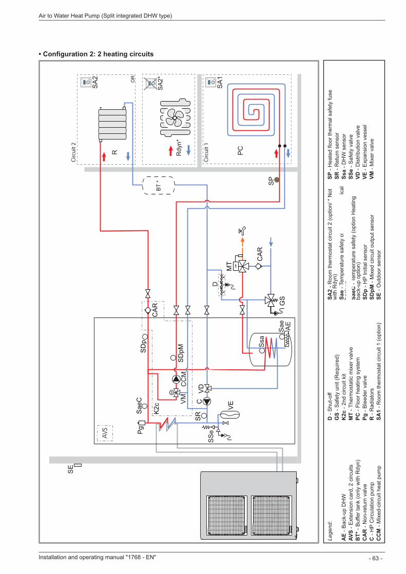
• Configuration 2: 2 heating circuits
Lege
nd:
AE
- Bac
k-up
DH
WAV
S - E
xten
sion
car
d, 2
circ
uits
BT*
- B
uffe
r tan
k (o
nly
with
Rdy
n)
CA
R -
Non
-ret
urn
valv
e C
- H
P C
ircul
atio
n pu
mp
CC
M -
Mix
ed-c
ircui
t hea
t pum
p
D -
Shu
t-off
GS
- Saf
ety
unit
(Req
uire
d)K
2c -
2nd
circ
uit k
itM
T - T
herm
osta
tic m
ixer
val
vePC
- Fl
oor h
eatin
g sy
stem
Pg -
Ble
eder
val
veR
- R
adia
tors
SA1
- Roo
m th
erm
osta
t circ
uit 1
(opt
ion)
SA2
- Roo
m th
erm
osta
t circ
uit 2
(opt
ion/
* N
ot
with
Rdy
n)Sa
e - T
empe
ratu
re s
afet
y of
dom
estic
ele
ctric
al
back
-up
SaeC
- Te
mpe
ratu
re s
afet
y (o
ptio
n H
eatin
g ba
ck-u
p op
tion)
SDp
- HP
Initi
al s
enso
rSD
pM -
Mix
ed c
ircui
t out
put s
enso
rSE
- O
utdo
or s
enso
r
SP -
Hea
ted
floor
ther
mal
saf
ety
fuse
SR -
Ret
urn
sens
orSs
a - D
HW
sen
sor
SSe
- Saf
ety
valv
eVD
- D
istri
butio
n va
lve
VE -
Exp
ansi
on v
esse
lVM
- M
ixer
val
ve
SE
Ssa
Sae AE
SR
VEC
VD
GS
MT C
AR
SD
pP
gS
aeC
SS
eD
R
OU
PC
SA
SA
Rdy
n*
OU
SA
*B
T *
M
SP
CC
MV
MS
DpM
K2c
CA
R
AVS
SA
1
SA
2
SA
2*
Circ
uit 2
Circ
uit 1
OR
Installation and operating manual "1768 - EN" - 63 -
Air to Water Heat Pump (Split integrated DHW type)
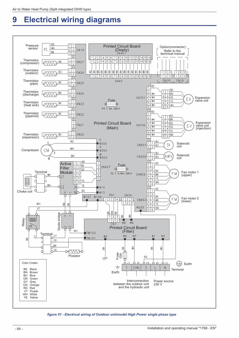
9 Electrical wiring diagrams
figure 51 - Electrical wiring of Outdoor unit model alféa excellia (single phase type)
Thermistor (expansion)
Expansion valve coil (Injecrtion)
Thermistor (pipe)
Thermistor (pipemid)
Thermistor (discharge)
Thermistor (outdoor)
Thermistor (compressor)
Pressure sensor
Choke coil
Posistor
Solenoid coil
Solenoid coil
Expansion valve coil
Fan motor 1 (upper)
Fan motor 2 (lower)
Option(connector)Refer to the
technical manual
Fuse
Fuse
Power source 230 V
Interconnection between the outdoor unit
and the hydraulic unit
F4 T 5A - 250 V
F2 T 3,15A - 250 V
Fuse
10
A
Rel
ay
Dio
de b
ridge
Terminal
Earth
Earth
Terminal
Terminal
Compressor
ActiveFilterModule
Printed Circuit Board (Main)
Printed Circuit Board (Disply)
Printed Circuit Board (Filter)
Thermistor (heat sink)
Color Codes
BK BlackBN BrownBU BlueGN GreenGY GreyOG OrangeRD RedVT Purple
WH WhiteYE Yellow
Installation and operating manual "1768 - EN"
Air to Water Heat Pump (Split integrated DHW type)
- 64 -
model High Power single phase type

figure 52 - Electrical wiring of Outdoor unit model alféa excellia (3-phase type)
BK
WH
RD
RD
RD
RD
RD
RD
RD
RD
RDRD
RD
RD
RDBN
BN
BN
BN
BN
BN
BN
BNYE
YE
YE
YE
YEGN
GN
GN
GN
GN
YE
YE
VT
OG
OG
OG
OG
OG
OG
WH
WH
WH
WH
WH
WH
WH
WH
WH
WH
WH
WH
BK BK
BK
BK
BK
BK
BK
BUBU BU
BU
BU
BUBU
BU
BU
BK
BKBK
BKBK
BK
BK
BK
BK
BKBK
BKBK
BK
BK
BK
BK
1 2 3 L1 L2 L3 N
ThermistorInj expansion
valve
Thermistor heatexchanger mid
Expansion
valve coil (Inj)
Thermistordischarge
pipe
Thermistor heat
exchanger out
Thermistoroutdoor temp.
Thermistorcompressor
temp.
Pressure
sensor
Reactor fan
Solenoid
coil
Solenoid coil (Inj)
Expansion
valve coil
Fan motor 1(upper)
Fan motor 2(lower)
Option (connector)
Fuse
Power source 3-phase 400 V
Interconnection between the outdoor unit and the hydraulic unit
F3 10A - 250 V
F2 3,15A - 250 V
F1 5A - 250 V
Reactors
Terminal
Compressor
Thermistor
(Heatsink inv.)
Inverter PCB assy
Capacitor PCB assy
Filter PCB assy
P.F.C. PCB assy
Controller PCB assy (Main PCB)
Thermistorheatsink PFC
Color Codes
BK Black BN Brown BU Blue GN Green GY Grey OG Orange RD Red VT Purple WH White YE Yellow
Installation and operating manual "1768 - EN" - 65 -
Air to Water Heat Pump (Split integrated DHW type)
model High Power 3-phase type
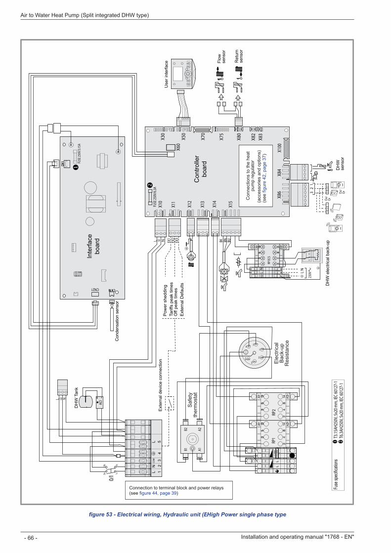
figure 53 - Electrical wiring, Hydraulic unit (Except installer's connections)
X10
X11
X12
X13
X14
X15
X30
X50
X70
X75
X80
X82
X83
X84
X86
X100
C.C
X60
0/I
M
2a 1a1b2b
EX1
EX2
EX3
BK BN BU
L N
32
1
RP EC
S
LN
LN
230V
ACI
L N
12
34
5L
NCO
ML
Ou/
Or
Ou/
Or3
21
32
1
CN21
T3
.15AH
250V
, 5x2
0 mm
, IEC 6
0127
-1
T6.3A
H250
V, 5x
20 m
m, IE
C 601
27-1
FUSE
250V
/3.15
A
FUSE
250V
/6.3A
Fuse
spec
ificati
ons
Con
dens
atio
n se
nsor
Con
trolle
rbo
ard
Inte
rface
boar
d
Ext
erna
l dev
ice
conn
ectio
n
Flow
se
nsor
Use
r int
erfa
ce Ret
urn
sens
or
Pow
er s
hedd
ing
Tarif
fs p
eak
times
Off
peak
tim
esE
xter
nal D
efau
lts
DH
W T
ank
DH
W e
lect
rical
bac
k-up
DH
Wse
nsor
Con
nect
ion
to te
rmin
al
bloc
k an
d po
wer
rela
ys
(see
figu
re 4
4, p
age
39)
Con
nect
ions
to th
e he
at
pum
p re
gula
tor
(acc
esso
ries
and
optio
ns)
(see
figu
re 4
2, p
age
37)
Installation and operating manual "1768 - EN"
Air to Water Heat Pump (Split integrated DHW type)
- 66 -
X10
X11
X12
X13
X14
X15
X30
X50
X70
X75
X80
X82
X83
X84
X86
X100
C.C
X60
0/I
M
2a 1a1b2b
EX1
EX2
EX3
BK BN BU
L N
32
1
RP EC
S
LN
LN
230V
ACI
L N
12
34
5L
NCO
ML
Ou/
Or
Ou/
Or3
21
32
1
RP1
RP2
RD1 RD
2
BU2
BU1
WH1
WH
2
A1
A2
B1
B2
CN21
T3
.15AH
250V
, 5x2
0 mm
, IEC 6
0127
-1
T6.3A
H250
V, 5x
20 m
m, IE
C 601
27-1
FUSE
250V
/3.15
A
FUSE
250V
/6.3A
Fuse
spec
ificati
ons
Con
dens
atio
n se
nsor
Con
trolle
rbo
ard
Inte
rface
boar
d
Ext
erna
l dev
ice
conn
ectio
n
Flow
se
nsor
Use
r int
erfa
ce Ret
urn
sens
or
Pow
er s
hedd
ing
Tarif
fs p
eak
times
Off
peak
tim
esE
xter
nal D
efau
lts
DH
W T
ank
DH
W e
lect
rical
bac
k-up
DH
Wse
nsor
Saf
ety
ther
mos
tat
Ele
ctric
al
Bac
k-up
R
esis
tanc
e
High Power single phase type
Connection to terminal block and power relays (see figure 44, page 39)
Con
nect
ions
to th
e he
at
pum
p re
gula
tor
(acc
esso
ries
and
optio
ns)
(see
figu
re 4
2, p
age
37)
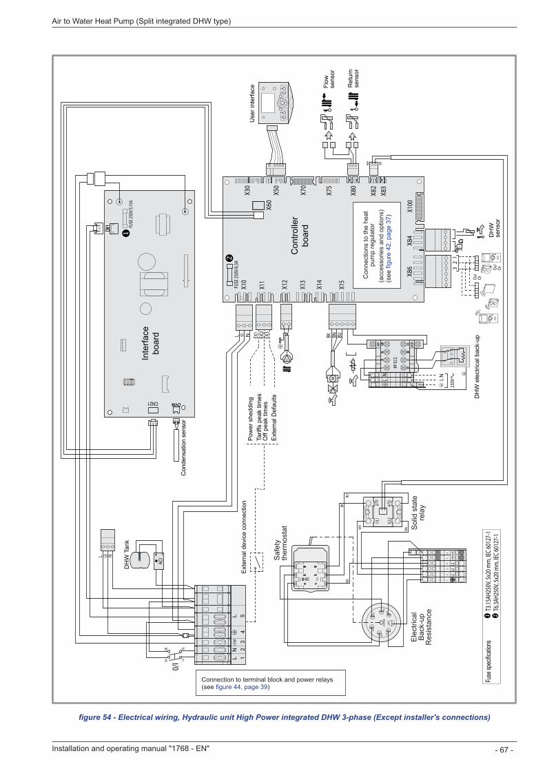
Installation and operating manual "1768 - EN" - 67 -
Air to Water Heat Pump (Split integrated DHW type)
X10
X11
X12
X13
X14
X15
X30
X50
X70
X75
X80
X82
X83
X84
X86
X100
C.C
X60
0/I
M
2a 1a1b2b
EX1
EX2
EX3
BK BN BU
L N
32
1
RP EC
S
LN
LN
230V
ACI
L N
12
34
5L
NCO
ML
Ou/
Or
Ou/
Or3
21
32
1
RD1
RD2
BU2
BU1
BK1BK
2CA
PILL
AIRE
GN/Y
E
12
34
56
L1L2
L3CO
MM
UN
1/L1
2/T1
3/L2
4/T2
WH
BN
RDBK
BU
BUWH
CN21
T3
.15AH
250V
, 5x2
0 mm
, IEC 6
0127
-1
T6.3A
H250
V, 5x
20 m
m, IE
C 601
27-1
FUSE
250V
/3.15
A
FUSE
250V
/6.3A
Fuse
spec
ificati
ons
Con
dens
atio
n se
nsor
Con
trolle
rbo
ard
Inte
rface
boar
d
Ext
erna
l dev
ice
conn
ectio
n
Flow
se
nsor
Use
r int
erfa
ce Ret
urn
sens
or
Pow
er s
hedd
ing
Tarif
fs p
eak
times
Off
peak
tim
esE
xter
nal D
efau
lts
DH
W T
ank
DH
W e
lect
rical
bac
k-up
DH
Wse
nsor
figure 54 - Electrical wiring, Hydraulic unit High Power integrated DHW 3-phase (Except installer's connections)
Ele
ctric
al
Bac
k-up
R
esis
tanc
e
Saf
ety
ther
mos
tat Sol
id s
tate
re
lay
Connection to terminal block and power relays (see figure 44, page 39)
Con
nect
ions
to th
e he
at
pum
p re
gula
tor
(acc
esso
ries
and
optio
ns)
(see
figu
re 4
2, p
age
37)
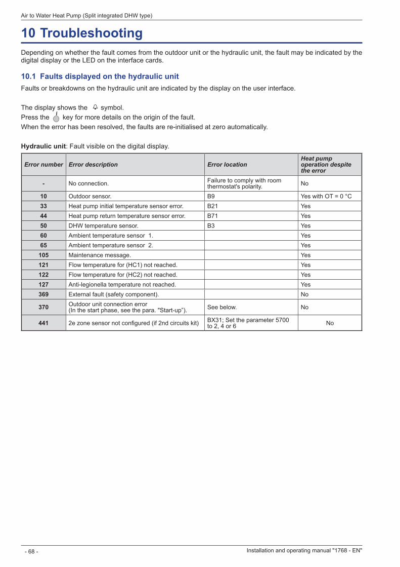
10 TroubleshootingDepending on whether the fault comes from the outdoor unit or the hydraulic unit, the fault may be indicated by the digital display or the LED on the interface cards.
10 .1 Faults displayed on the hydraulic unitFaults or breakdowns on the hydraulic unit are indicated by the display on the user interface.
The display shows the symbol.Press the key for more details on the origin of the fault.When the error has been resolved, the faults are re-initialised at zero automatically.
Hydraulic unit: Fault visible on the digital display.
Error number Error description Error locationHeat pump operation despite the error
- No connection. Failure to comply with room thermostat's polarity. No
10 Outdoor sensor. B9 Yes with OT = 0 °C33 Heat pump initial temperature sensor error. B21 Yes44 Heat pump return temperature sensor error. B71 Yes50 DHW temperature sensor. B3 Yes60 Ambient temperature sensor 1. Yes65 Ambient temperature sensor 2. Yes
105 Maintenance message. Yes121 Flow temperature for (HC1) not reached. Yes122 Flow temperature for (HC2) not reached. Yes127 Anti-legionella temperature not reached. Yes369 External fault (safety component). No
370 Outdoor unit connection error (In the start phase, see the para. "Start-up”). See below. No
441 2e zone sensor not configured (if 2nd circuits kit) BX31; Set the parameter 5700 to 2, 4 or 6 No
Installation and operating manual "1768 - EN"
Air to Water Heat Pump (Split integrated DHW type)
- 68 -
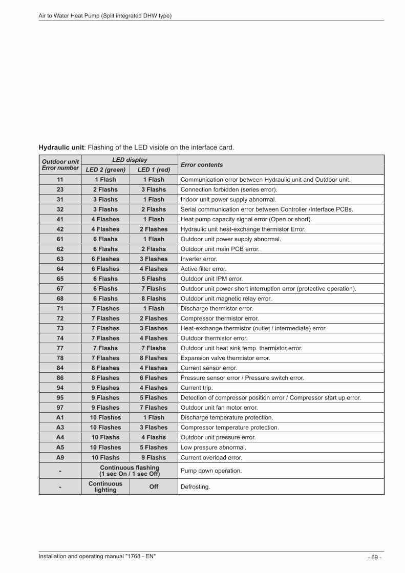
Hydraulic unit: Flashing of the LED visible on the interface card.
Outdoor unit Error number
LED displayError contents
LED 2 (green) LED 1 (red)11 1 Flash 1 Flash Communication error between Hydraulic unit and Outdoor unit.23 2 Flashs 3 Flashs Connection forbidden (series error).31 3 Flashs 1 Flash Indoor unit power supply abnormal.32 3 Flashs 2 Flashs Serial communication error between Controller /Interface PCBs.41 4 Flashes 1 Flash Heat pump capacity signal error (Open or short).42 4 Flashes 2 Flashes Hydraulic unit heat-exchange thermistor Error.61 6 Flashs 1 Flash Outdoor unit power supply abnormal.62 6 Flashs 2 Flashs Outdoor unit main PCB error.63 6 Flashes 3 Flashes Inverter error.64 6 Flashes 4 Flashes Active filter error.65 6 Flashs 5 Flashs Outdoor unit IPM error.67 6 Flashs 7 Flashs Outdoor unit power short interruption error (protective operation).68 6 Flashs 8 Flashs Outdoor unit magnetic relay error.71 7 Flashes 1 Flash Discharge thermistor error.72 7 Flashes 2 Flashes Compressor thermistor error.73 7 Flashes 3 Flashes Heat-exchange thermistor (outlet / intermediate) error.74 7 Flashes 4 Flashes Outdoor thermistor error.77 7 Flashs 7 Flashs Outdoor unit heat sink temp. thermistor error.78 7 Flashes 8 Flashes Expansion valve thermistor error.84 8 Flashes 4 Flashes Current sensor error.86 8 Flashes 6 Flashes Pressure sensor error / Pressure switch error.94 9 Flashes 4 Flashes Current trip.95 9 Flashes 5 Flashes Detection of compressor position error / Compressor start up error.97 9 Flashes 7 Flashes Outdoor unit fan motor error.A1 10 Flashes 1 Flash Discharge temperature protection.A3 10 Flashes 3 Flashes Compressor temperature protection.A4 10 Flashs 4 Flashs Outdoor unit pressure error.A5 10 Flashes 5 Flashes Low pressure abnormal.
A9 10 Flashs 9 Flashs Current overload error.
- Continuous flashing (1 sec On / 1 sec Off) Pump down operation.
- Continuous lighting Off Defrosting.
Installation and operating manual "1768 - EN" - 69 -
Air to Water Heat Pump (Split integrated DHW type)
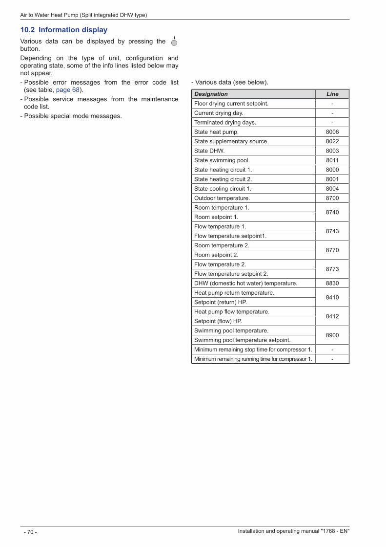
10 .2 Information displayVarious data can be displayed by pressing the button.Depending on the type of unit, configuration and operating state, some of the info lines listed below may not appear. - Possible error messages from the error code list (see table, page 68). - Possible service messages from the maintenance code list. - Possible special mode messages.
- Various data (see below).
Designation LineFloor drying current setpoint. -Current drying day. -Terminated drying days. -State heat pump. 8006State supplementary source. 8022State DHW. 8003State swimming pool. 8011State heating circuit 1. 8000State heating circuit 2. 8001State cooling circuit 1. 8004Outdoor temperature. 8700Room temperature 1.
8740Room setpoint 1.Flow temperature 1.
8743Flow temperature setpoint1.Room temperature 2.
8770Room setpoint 2.Flow temperature 2.
8773Flow temperature setpoint 2.DHW (domestic hot water) temperature. 8830Heat pump return temperature.
8410Setpoint (return) HP.Heat pump flow temperature.
8412Setpoint (flow) HP.Swimming pool temperature.
8900Swimming pool temperature setpoint.Minimum remaining stop time for compressor 1. -Minimum remaining running time for compressor 1. -
Installation and operating manual "1768 - EN"
Air to Water Heat Pump (Split integrated DHW type)
- 70 -

Installation and operating manual "1768 - EN" - 71 -
Air to Water Heat Pump (Split integrated DHW type)
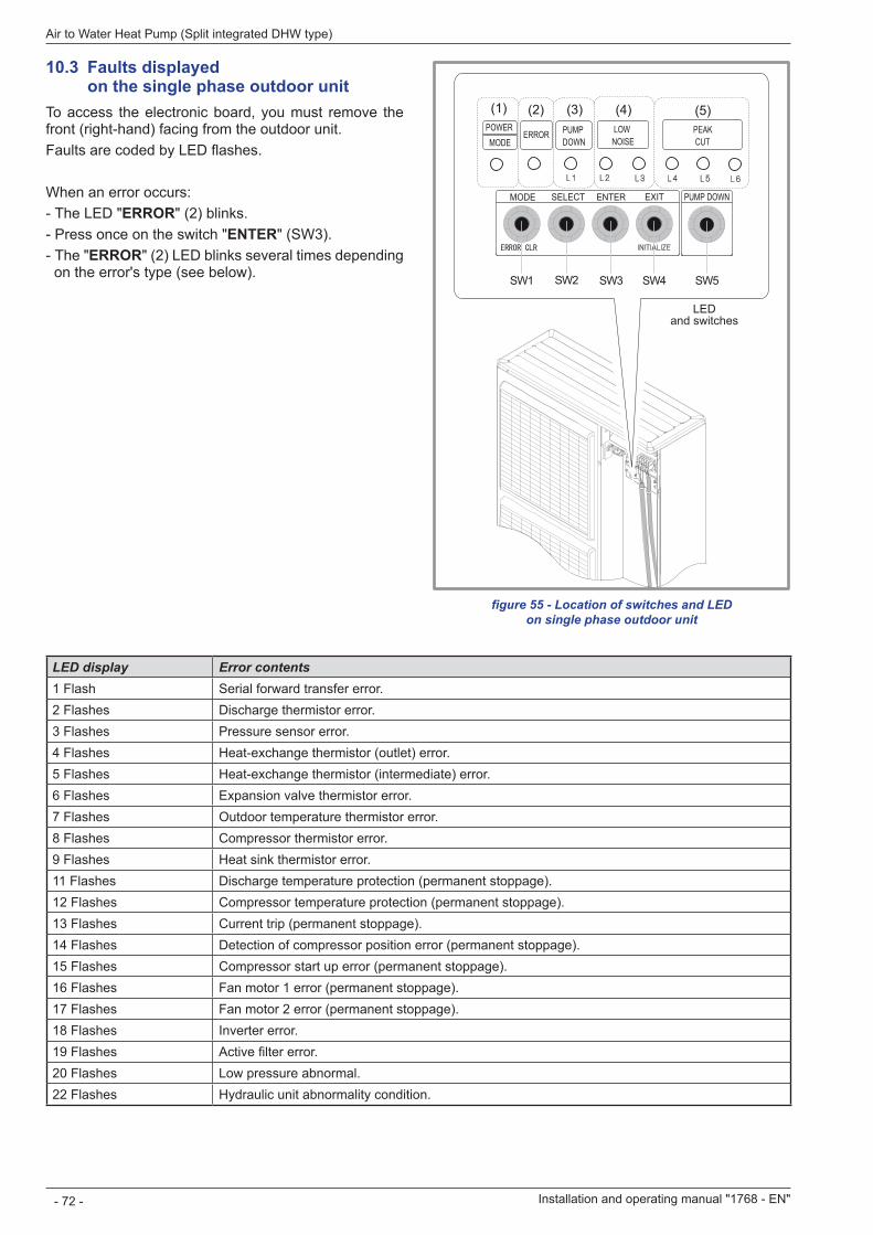
10 .3 Faults displayed on the single phase outdoor unitTo access the electronic board, you must remove the front (right-hand) facing from the outdoor unit.Faults are coded by LED flashes.
When an error occurs: - The LED "ERROR" (2) blinks. - Press once on the switch "ENTER" (SW3). - The "ERROR" (2) LED blinks several times depending on the error's type (see below).
LED display Error contents1 Flash Serial forward transfer error.2 Flashes Discharge thermistor error.3 Flashes Pressure sensor error.4 Flashes Heat-exchange thermistor (outlet) error.5 Flashes Heat-exchange thermistor (intermediate) error.6 Flashes Expansion valve thermistor error.7 Flashes Outdoor temperature thermistor error.8 Flashes Compressor thermistor error.9 Flashes Heat sink thermistor error.11 Flashes Discharge temperature protection (permanent stoppage).12 Flashes Compressor temperature protection (permanent stoppage).13 Flashes Current trip (permanent stoppage).14 Flashes Detection of compressor position error (permanent stoppage).15 Flashes Compressor start up error (permanent stoppage).16 Flashes Fan motor 1 error (permanent stoppage).17 Flashes Fan motor 2 error (permanent stoppage).18 Flashes Inverter error.19 Flashes Active filter error.20 Flashes Low pressure abnormal.22 Flashes Hydraulic unit abnormality condition.
figure 55 - Location of switches and LED on single phase outdoor unit
SW1 SW2 SW3 SW4 SW5
(1) (2) (3) (4) (5)
LED and switches
Installation and operating manual "1768 - EN"
Air to Water Heat Pump (Split integrated DHW type)
- 72 -
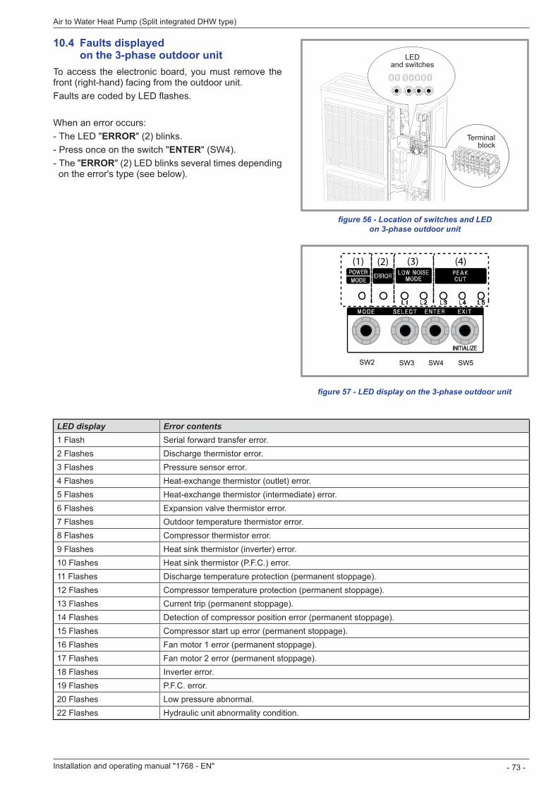
10 .4 Faults displayed on the 3-phase outdoor unitTo access the electronic board, you must remove the front (right-hand) facing from the outdoor unit.Faults are coded by LED flashes.
When an error occurs: - The LED "ERROR" (2) blinks. - Press once on the switch "ENTER" (SW4). - The "ERROR" (2) LED blinks several times depending on the error's type (see below).
figure 56 - Location of switches and LED on 3-phase outdoor unit
SW2 SW3 SW4 SW5
(1) (2) (3) (4)
figure 57 - LED display on the 3-phase outdoor unit
LED display Error contents1 Flash Serial forward transfer error.2 Flashes Discharge thermistor error.3 Flashes Pressure sensor error.4 Flashes Heat-exchange thermistor (outlet) error.5 Flashes Heat-exchange thermistor (intermediate) error.6 Flashes Expansion valve thermistor error.7 Flashes Outdoor temperature thermistor error.8 Flashes Compressor thermistor error.9 Flashes Heat sink thermistor (inverter) error.10 Flashes Heat sink thermistor (P.F.C.) error.11 Flashes Discharge temperature protection (permanent stoppage).12 Flashes Compressor temperature protection (permanent stoppage).13 Flashes Current trip (permanent stoppage).14 Flashes Detection of compressor position error (permanent stoppage).15 Flashes Compressor start up error (permanent stoppage).16 Flashes Fan motor 1 error (permanent stoppage).17 Flashes Fan motor 2 error (permanent stoppage).18 Flashes Inverter error.19 Flashes P.F.C. error.20 Flashes Low pressure abnormal.22 Flashes Hydraulic unit abnormality condition.
LED and switches
Terminal block
Installation and operating manual "1768 - EN" - 73 -
Air to Water Heat Pump (Split integrated DHW type)
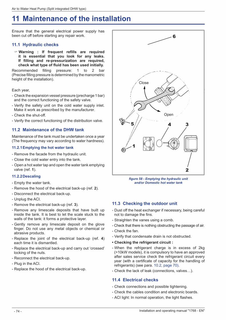
figure 58 - Emptying the hydraulic unit and/or Domestic hot water tank
Ensure that the general electrical power supply has been cut off before starting any repair work.
11 .1 Hydraulic checks " Warning : If frequent refills are required it is essential that you look for any leaks . If filling and re-pressurization are required, check what type of fluid has been used initially.
Recommended filling pressure: 1 to 2 bar (Precise filling pressure is determined by the manometric height of the installation).
Each year, - Check the expansion vessel pressure (precharge 1 bar) and the correct functioning of the safety valve. - Verify the safety unit on the cold water supply inlet. Make it work as prescribed by the manufacturer. - Check the shut-off. - Verify the correct functioning of the distribution valve.
11 .2 Maintenance of the DHW tankMaintenance of the tank must be undertaken once a year (The frequency may vary according to water hardness).
11 .2 .1 Emptying the hot water tank - Remove the facade from the hydraulic unit. - Close the cold water entry into the tank. - Open a hot water tap and open the water tank emptying valve (ref. 1).
11 .2 .2 Descaling - Empty the water tank. - Remove the hood of the electrical back-up (ref. 2). - Disconnect the electrical back-up. - Unplug the ACI. - Remove the electrical back-up (ref. 3). - Remove any limescale deposits that have built up inside the tank. It is best to let the scale stuck to the walls of the tank: it forms a protective layer. - Gently remove any limescale deposit on the glove finger. Do not use any metal objects or chemical or abrasive products. - Replace the joint of the electrical back-up (ref. 4) each time it is dismantled. - Replace the electrical back-up and carry out ‘crossed’ locking of the nuts. - Reconnect the electrical back-up. - Plug in the ACI. - Replace the hood of the electrical back-up.
1
5
6
2
4 3
11 .3 Checking the outdoor unit - Dust off the heat exchanger if necessary, being careful not to damage the fins. - Straighten the vanes using a comb. - Check that there is nothing obstructing the passage of air. - Check the fan. - Verify that condensate drain is not obstructed.
• Checking the refrigerant circuit : - When the refrigerant charge is in excess of 2kg (>10kW models), it is compulsory to have an approved after sales service check the refrigerant circuit every year (with a certificate of capacity for the handling of refrigerants) (see para. 10.2, page 70) - Check the lack of leak (connections, valves…).
11 .4 Electrical checks - Check connections and possible tightening. - Check the cables condition and electronic boards. - ACI light: In normal operation, the light flashes.
Close
Open
11 Maintenance of the installation
Installation and operating manual "1768 - EN"
Air to Water Heat Pump (Split integrated DHW type)
- 74 -
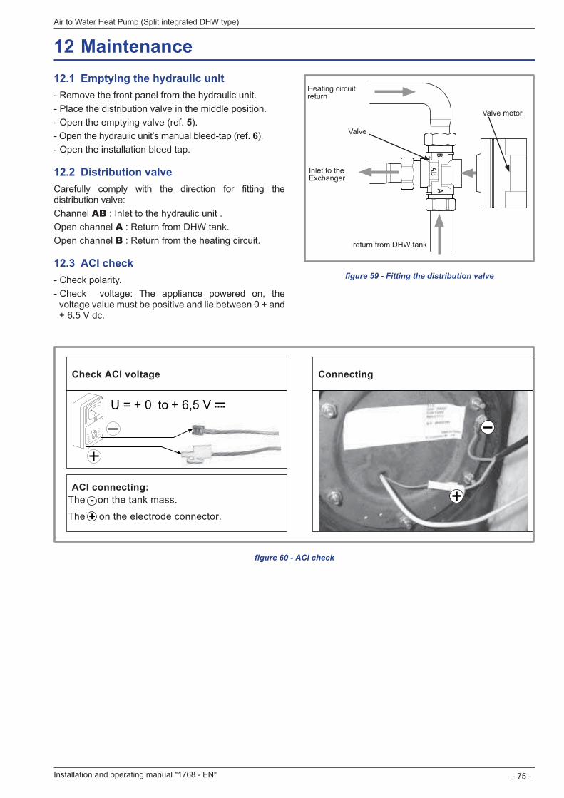
BA
AB
figure 59 - Fitting the distribution valve
12 .1 Emptying the hydraulic unit - Remove the front panel from the hydraulic unit. - Place the distribution valve in the middle position. - Open the emptying valve (ref. 5). - Open the hydraulic unit’s manual bleed-tap (ref. 6). - Open the installation bleed tap.
12 .2 Distribution valveCarefully comply with the direction for fitting the distribution valve:Channel AB : Inlet to the hydraulic unit .Open channel A : Return from DHW tank.Open channel B : Return from the heating circuit.
12 .3 ACI check - Check polarity. - Check voltage: The appliance powered on, the voltage value must be positive and lie between 0 + and + 6.5 V dc.
U = + 0 + 6,5 V
Check ACI voltage Connecting
ACI connecting:The on the tank mass.
The on the electrode connector.-+
to
figure 60 - ACI check
Inlet to the Exchanger
Heating circuit return
return from DHW tank
Valve
Valve motor
12 Maintenance
Installation and operating manual "1768 - EN" - 75 -
Air to Water Heat Pump (Split integrated DHW type)
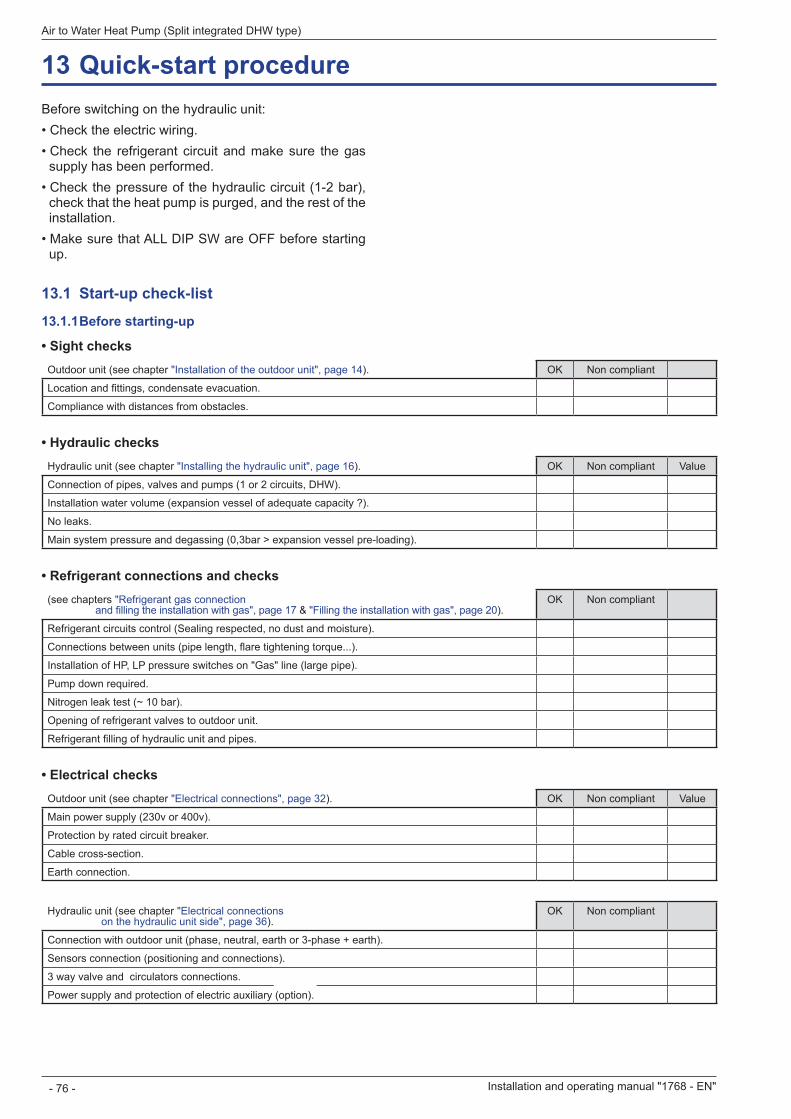
Before switching on the hydraulic unit:• Check the electric wiring.• Check the refrigerant circuit and make sure the gas
supply has been performed.• Check the pressure of the hydraulic circuit (1-2 bar),
check that the heat pump is purged, and the rest of the installation.
• Make sure that ALL DIP SW are OFF before starting up
13 .1 Start-up check-list
13 .1 .1 Before starting-up
• Sight checksOutdoor unit (see chapter "Installation of the outdoor unit", page 14). OK Non compliant
Location and fittings, condensate evacuation.
Compliance with distances from obstacles. • Hydraulic checks
Hydraulic unit (see chapter "Installing the hydraulic unit", page 16). OK Non compliant Value
Connection of pipes, valves and pumps (1 or 2 circuits, DHW).
Installation water volume (expansion vessel of adequate capacity ?).
No leaks.
Main system pressure and degassing (0,3bar > expansion vessel pre-loading). • Refrigerant connections and checks
(see chapters "Refrigerant gas connection and filling the installation with gas", page 17 & "Filling the installation with gas", page 20).
OK Non compliant
Refrigerant circuits control (Sealing respected, no dust and moisture).
Connections between units (pipe length, flare tightening torque...).
Installation of HP, LP pressure switches on "Gas" line (large pipe).
Pump down required.
Nitrogen leak test (~ 10 bar).
Opening of refrigerant valves to outdoor unit.
Refrigerant filling of hydraulic unit and pipes. • Electrical checks
Outdoor unit (see chapter "Electrical connections", page 32). OK Non compliant Value
Main power supply (230v or 400v).
Protection by rated circuit breaker.
Cable cross-section.
Earth connection.
Hydraulic unit (see chapter "Electrical connections on the hydraulic unit side", page 36).
OK Non compliant
Connection with outdoor unit (phase, neutral, earth or 3-phase + earth).
Sensors connection (positioning and connections).
3 way valve and circulators connections.
Power supply and protection of electric auxiliary (option).
13 Quick-start procedure
Installation and operating manual "1768 - EN"
Air to Water Heat Pump (Split integrated DHW type)
- 76 -
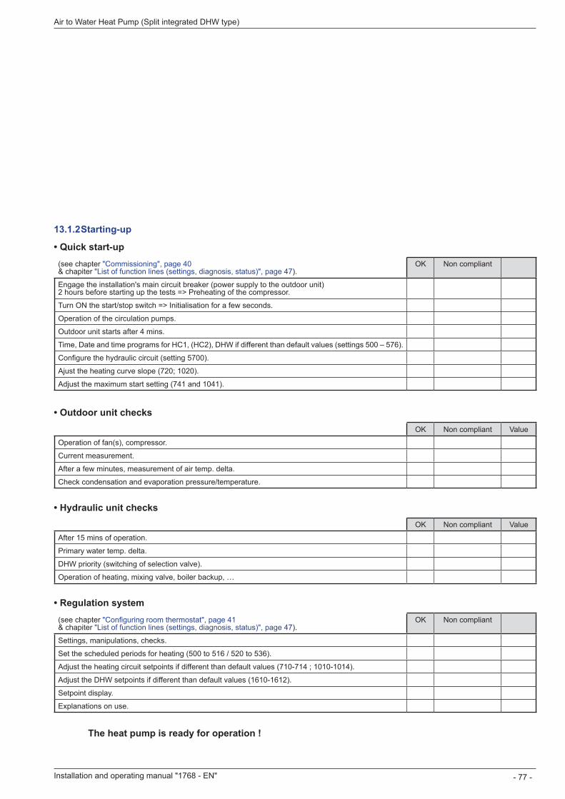
13 .1 .2 Starting-up
• Quick start-up(see chapter "Commissioning", page 40 & chapiter "List of function lines (settings, diagnosis, status)", page 47).
OK Non compliant
Engage the installation's main circuit breaker (power supply to the outdoor unit) 2 hours before starting up the tests => Preheating of the compressor.
Turn ON the start/stop switch => Initialisation for a few seconds.
Operation of the circulation pumps.
Outdoor unit starts after 4 mins.
Time, Date and time programs for HC1, (HC2), DHW if different than default values (settings 500 – 576).
Configure the hydraulic circuit (setting 5700).
Ajust the heating curve slope (720; 1020).
Adjust the maximum start setting (741 and 1041).
• Outdoor unit checksOK Non compliant Value
Operation of fan(s), compressor.
Current measurement.
After a few minutes, measurement of air temp. delta.
Check condensation and evaporation pressure/temperature. • Hydraulic unit checks
OK Non compliant Value
After 15 mins of operation.
Primary water temp. delta.
DHW priority (switching of selection valve).
Operation of heating, mixing valve, boiler backup, … • Regulation system
(see chapter "Configuring room thermostat", page 41 & chapiter "List of function lines (settings, diagnosis, status)", page 47).
OK Non compliant
Settings, manipulations, checks.
Set the scheduled periods for heating (500 to 516 / 520 to 536).
Adjust the heating circuit setpoints if different than default values (710-714 ; 1010-1014).
Adjust the DHW setpoints if different than default values (1610-1612).
Setpoint display.
Explanations on use.
The heat pump is ready for operation !
Installation and operating manual "1768 - EN" - 77 -
Air to Water Heat Pump (Split integrated DHW type)
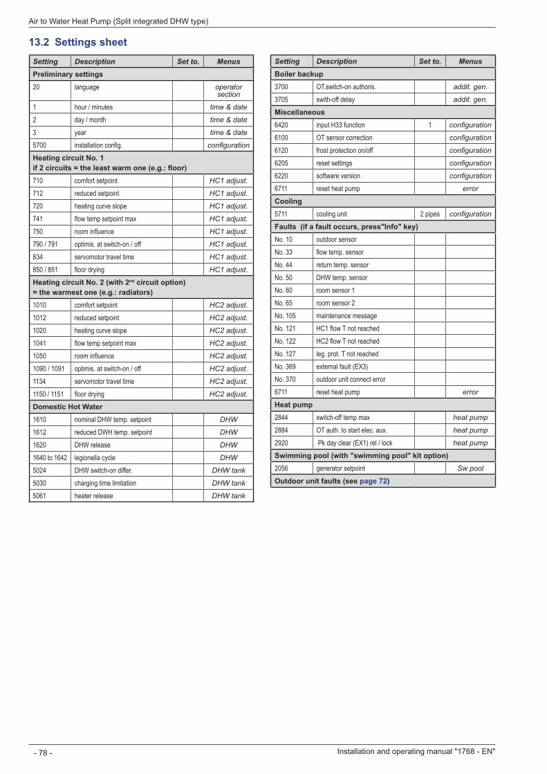
13 .2 Settings sheetSetting Description Set to. MenusPreliminary settings20 language operator
section
1 hour / minutes time & date
2 day / month time & date
3 year time & date
5700 installation config. configuration
Heating circuit No . 1if 2 circuits = the least warm one (e.g.: floor)710 comfort setpoint HC1 adjust.
712 reduced setpoint HC1 adjust.
720 heating curve slope HC1 adjust.
741 flow temp setpoint max HC1 adjust.
750 room influence HC1 adjust.
790 / 791 optimis. at switch-on / off HC1 adjust.
834 servomotor travel time HC1 adjust.
850 / 851 floor drying HC1 adjust.
Heating circuit No. 2 (with 2nd circuit option)= the warmest one (e.g.: radiators)1010 comfort setpoint HC2 adjust.
1012 reduced setpoint HC2 adjust.
1020 heating curve slope HC2 adjust.
1041 flow temp setpoint max HC2 adjust.
1050 room influence HC2 adjust.
1090 / 1091 optimis. at switch-on / off HC2 adjust.
1134 servomotor travel time HC2 adjust.
1150 / 1151 floor drying HC2 adjust.
Domestic Hot Water1610 nominal DHW temp. setpoint DHW
1612 reduced DWH temp. setpoint DHW
1620 DHW release DHW
1640 to 1642 legionella cycle DHW
5024 DHW switch-on differ. DHW tank
5030 charging time limitation DHW tank
5061 heater release DHW tank
Setting Description Set to. MenusBoiler backup3700 OT.switch-on authoris. addit. gen.
3705 swith-off delay addit. gen.
Miscellaneous6420 input H33 function 1 configuration
6100 OT sensor correction configuration
6120 frost protection on/off configuration
6205 reset settings configuration
6220 software version configuration
6711 reset heat pump error
Cooling5711 cooling unit 2 pipes configuration
Faults (if a fault occurs, press"Info" key)No. 10 outdoor sensorNo. 33 flow temp. sensorNo. 44 return temp. sensorNo. 50 DHW temp. sensorNo. 60 room sensor 1No. 65 room sensor 2No. 105 maintenance messageNo. 121 HC1 flow T not reachedNo. 122 HC2 flow T not reachedNo. 127 leg. prot. T not reachedNo. 369 external fault (EX3)No. 370 outdoor unit connect error6711 reset heat pump error
Heat pump2844 switch-off temp max heat pump
2884 OT auth. to start elec. aux. heat pump
2920 Pk day clear (EX1) rel / lock heat pump
Swimming pool (with "swimming pool" kit option)2056 generator setpoint Sw pool
Outdoor unit faults (see page 72)
Installation and operating manual "1768 - EN"
Air to Water Heat Pump (Split integrated DHW type)
- 78 -
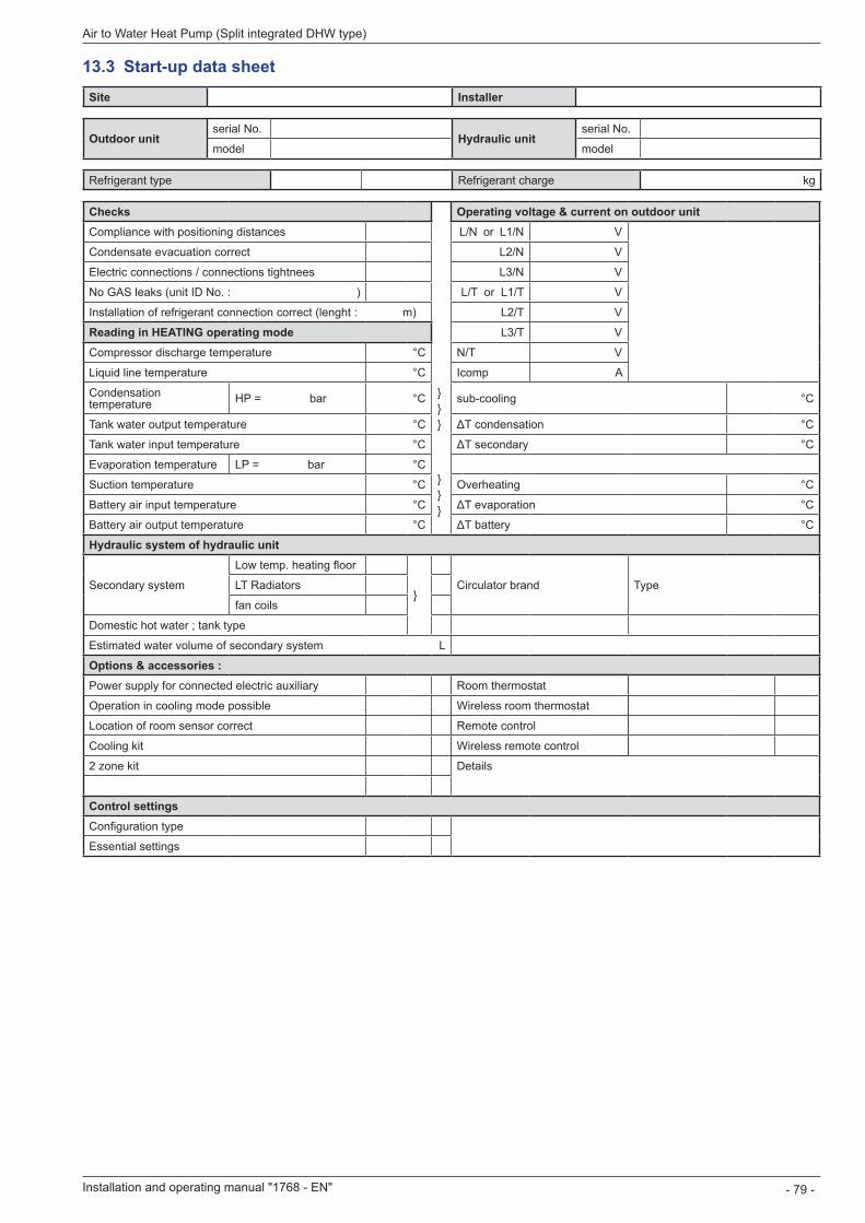
13 .3 Start-up data sheetSite Installer
Outdoor unitserial No.
Hydraulic unitserial No.
model model
Refrigerant type Refrigerant charge kg
Checks Operating voltage & current on outdoor unitCompliance with positioning distances L/N or L1/N V
Condensate evacuation correct L2/N V
Electric connections / connections tightnees L3/N V
No GAS leaks (unit ID No. : ) L/T or L1/T V
Installation of refrigerant connection correct (lenght : m) L2/T V
Reading in HEATING operating mode L3/T V
Compressor discharge temperature °C N/T V
Liquid line temperature °C
}}}
Icomp A
Condensation temperature HP = bar °C sub-cooling °C
Tank water output temperature °C ΔT condensation °C
Tank water input temperature °C ΔT secondary °C
Evaporation temperature LP = bar °C}}}
Suction temperature °C Overheating °C
Battery air input temperature °C ΔT evaporation °C
Battery air output temperature °C ΔT battery °C
Hydraulic system of hydraulic unit
Secondary system
Low temp. heating floor
}Circulator brand TypeLT Radiators
fan coils
Domestic hot water ; tank type
Estimated water volume of secondary system L
Options & accessories :Power supply for connected electric auxiliary Room thermostat T55
Operation in cooling mode possible Wireless room thermostat T58
Location of room sensor correct Remote control T75
Cooling kit Wireless remote control T78
2 zone kit Details
Control settingsConfiguration type
Essential settings
Installation and operating manual "1768 - EN" - 79 -
Air to Water Heat Pump (Split integrated DHW type)
Room thermostat
Wireless room thermostat
Remote control
Wireless remote control
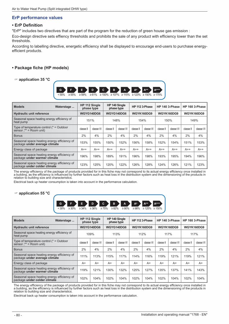
Installation and operating manual "1768 - EN"
Air to Water Heat Pump (Split integrated DHW type)
- 80 -
• Package fiche (HP models)
" application 35 °C
A+++A++G F E D C B A A+
< 55% ≥ 55% ≥ 59% ≥ 61% ≥ 100% ≥ 107% ≥ 115% ≥ 123% ≥ 150% ≥ 175%
Models Waterstage . . . HP 112 Single phase type
HP 140 Single phase type HP 112 3-Phase HP 140 3-Phase HP 160 3-Phase
Hydraulic unit reference WGYG140DG6 WGYG140DG6 WGYK160DG9 WGYK160DG9 WGYK160DG9Seasonal space heating energy efficiency of heat pump 151% 148% 154% 150% 149%
Type of temperature control (* = Outdoor sensor ;** = Room unit) classe II classe VI classe II classe VI classe II classe VI classe II classe VI classe II classe VI
Bonus 2% 4% 2% 4% 2% 4% 2% 4% 2% 4%
Seasonal space heating energy efficiency of package under average climate 153% 155% 150% 152% 156% 158% 152% 154% 151% 153%
Energy class of package A++ A++ A++ A++ A++ A++ A++ A++ A++ A++
Seasonal space heating energy efficiency of package under warmer climate 196% 198% 189% 191% 196% 198% 193% 195% 194% 196%
Seasonal space heating energy efficiency of package under colder climate 123% 125% 120% 122% 126% 128% 124% 126% 121% 123%
The energy efficiency of the package of products provided for in this fiche may not correspond to its actual energy efficiency once installed in a building, as the efficiency is influenced by further factors such as heat loss in the distribution system and the dimensioning of the products in relation to building size and characteristics.Electrical back up heater consumption is taken into account in the performance calculation.
" application 55 °C
A+++A++G F E D C B A A+
< 30% ≥ 30% ≥ 34% ≥ 36% ≥ 75% ≥ 82% ≥ 90% ≥ 98% ≥ 125% ≥ 150%
Models Waterstage . . . HP 112 Single phase type
HP 140 Single phase type HP 112 3-Phase HP 140 3-Phase HP 160 3-Phase
Hydraulic unit reference WGYG140DG6 WGYG140DG6 WGYK160DG9 WGYK160DG9 WGYK160DG9Seasonal space heating energy efficiency of heat pump 109% 113% 112% 117% 117%
Type of temperature control (* = Outdoor sensor ;** = Room unit) classe II classe VI classe II classe VI classe II classe VI classe II classe VI classe II classe VI
Bonus 2% 4% 2% 4% 2% 4% 2% 4% 2% 4%
Seasonal space heating energy efficiency of package under average climate 111% 113% 115% 117% 114% 116% 119% 121% 119% 121%
Energy class of package A+ A+ A+ A+ A+ A+ A+ A+ A+ A+
Seasonal space heating energy efficiency of package under warmer climate 119% 121% 130% 132% 125% 127% 135% 137% 141% 143%
Seasonal space heating energy efficiency of package under colder climate 102% 104% 102% 104% 102% 104% 102% 104% 102% 104%
The energy efficiency of the package of products provided for in this fiche may not correspond to its actual energy efficiency once installed in a building, as the efficiency is influenced by further factors such as heat loss in the distribution system and the dimensioning of the products in relation to building size and characteristics.Electrical back up heater consumption is taken into account in the performance calculation.
• ErP Definition"ErP" includes two directives that are part of the program for the reduction of green house gas emission :Eco-design directive sets effiency thresholds and prohibits the sale of any product with efficiency lower than the set thresholds.According to labelling directive, energetic efficiency shall be displayed to encourage end-users to purchase energy-efficient products.
ErP performance values
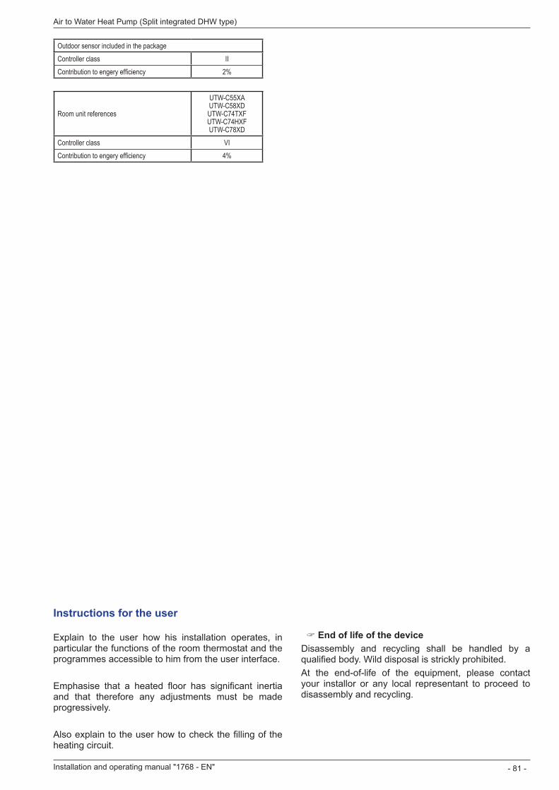
Installation and operating manual "1768 - EN" - 81 -
Air to Water Heat Pump (Split integrated DHW type)
Outdoor sensor included in the packageController class IIContribution to engery efficiency 2%
Room unit references
UTW-C55XA UTW-C58XD UTW-C74TXF UTW-C74HXF UTW-C78XD
Controller class VIContribution to engery efficiency 4%
Instructions for the user
Explain to the user how his installation operates, in particular the functions of the room thermostat and the programmes accessible to him from the user interface.
Emphasise that a heated floor has significant inertia and that therefore any adjustments must be made progressively.
Also explain to the user how to check the filling of the heating circuit.
" End of life of the deviceDisassembly and recycling shall be handled by a qualified body. Wild disposal is strickly prohibited.At the end-of-life of the equipment, please contact your installor or any local representant to proceed to disassembly and recycling.
Date of installation :
Contact of your heating technician or your after-sales service.
This appliance is marked with this symbol. This means that electrical and electronic products shall not be mixed with general household waste. European Community countries(*), Norway, Iceland and Liechtenstein should have a dedicated collection system for these products. Do not try to dismantle the system yourself as this could have harmful effects on your health and on the environment. The dismantling and treatment of refrigerant, oil and other parts must be done by a qualified installer in accordance with relevant local and national regulations. This appliance must be treated at a specialized treatment facility for re-use, recycling and other forms of recovery and shall not be disposed of in the municipal waste stream. Please contact the installer or local authority for more information. * subject to the national law of each member state
Mat
érie
l suj
et à
mod
ifica
tions
san
s pr
éavi
s - D
ocum
ent n
on c
ontra
ctue
l
Complies with : - Low voltage directive 2006/95/EC, under standard EN 60335-1 and EN 60335-2-40. - Electromagnetic compatibility Diretive 2004/108/EC, - Directive 2006/42/EC Machinery, - Directive for pressurised equipment 97/23/EC, - Eco-design directive 2009/125/CE, - Labelling directive2010/30/CE.
This appliance also conforms to: - Regulation 842/2006 of the european parliament on certain fluorinated greenhouse gases. - The standards relating to the product and the testing methods used: Air-conditioners, Refrigerant units and heat pumps with compressor driven by electric motor for heating and Refrigerant EN 14511-1, 14511-2, 14511-3, and 14511-4.
- To standard EN 12102: Air-conditioners, heat pumps and dehumidifiers with compressor driven by electric motor. Measurement of airborne noise. Determination of acoustic power level.