Embed Size (px)
Citation preview
AIRBUS INDUSTRIE A310
TOWING
1. General
The A310 is designed with means for conventional tractor towing.
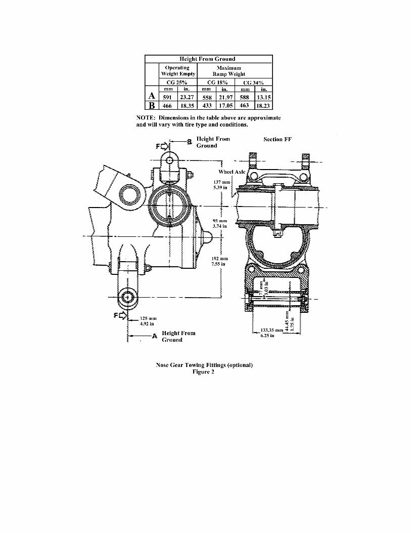
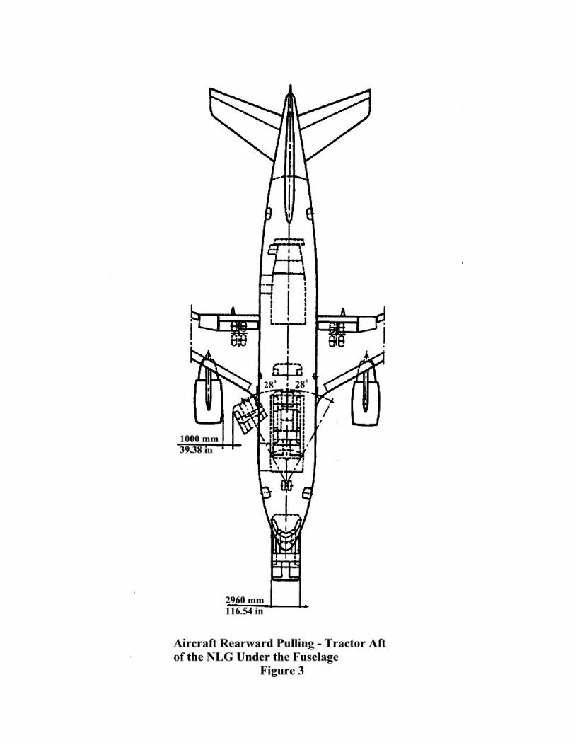
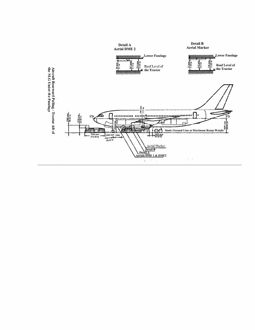
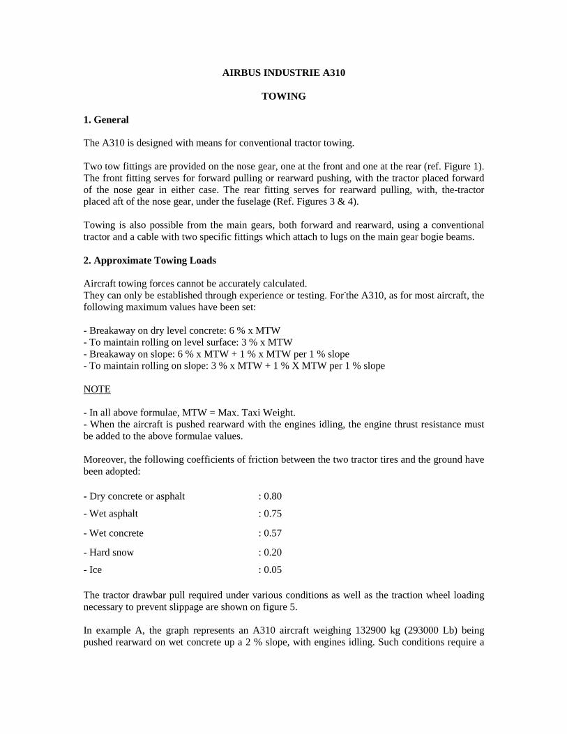
Two tow fittings are provided on the nose gear, one at the front and one at the rear (ref. Figure 1). The front fitting serves for forward pulling or rearward pushing, with the tractor placed forward of the nose gear in either case. The rear fitting serves for rearward pulling, with, the-tractor placed aft of the nose gear, under the fuselage (Ref. Figures 3 & 4).
Towing is also possible from the main gears, both forward and rearward, using a conventional tractor and a cable with two specific fittings which attach to lugs on the main gear bogie beams.
2. Approximate Towing Loads
Aircraft towing forces cannot be accurately calculated.They can only be established through experience or testing. For-the A310, as for most aircraft, the following maximum values have been set:
- Breakaway on dry level concrete: 6 % x MTW- To maintain rolling on level surface: 3 % x MTW- Breakaway on slope: 6 % x MTW + 1 % x MTW per 1 % slope- To maintain rolling on slope: 3 % x MTW + 1 % X MTW per 1 % slope
NOTE
- In all above formulae, MTW = Max. Taxi Weight.- When the aircraft is pushed rearward with the engines idling, the engine thrust resistance must be added to the above formulae values.
Moreover, the following coefficients of friction between the two tractor tires and the ground have been adopted:
- Dry concrete or asphalt : 0.80
- Wet asphalt : 0.75
- Wet concrete : 0.57
- Hard snow : 0.20
- Ice : 0.05
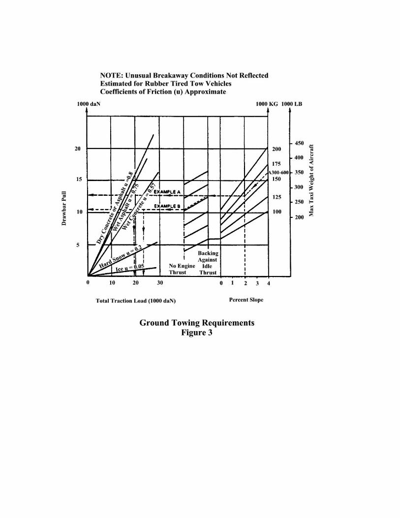
The tractor drawbar pull required under various conditions as well as the traction wheel loading necessary to prevent slippage are shown on figure 5.
In example A, the graph represents an A310 aircraft weighing 132900 kg (293000 Lb) being pushed rearward on wet concrete up a 2 % slope, with engines idling. Such conditions require a
9000 daN (20200 lbf) drawbar pull and a minimum 15000 daN (33700 lbf) load on the traction wheels.
In example B, the graph. represents an A310 aircraft weighing 132900 kg (293000 Lb) being pushed rearward on wet concrete up a 2 % slope, with engines idling. Such conditions require a 11000 daN (24700 lbf) drawbar pull and a minimum 15000 daN (33700 lbf) load on the traction wheels.
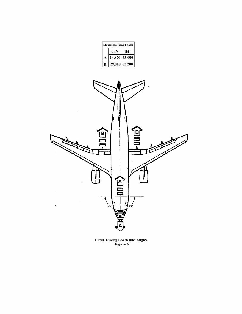
3. Limit Loads and Angles
The limit towing loads and angles are shown in figure 6.
Whatever towing arrangement used, the steering angle allowed on each side of the aircraft centerline is only 95° when control lever on the interphone box is disengaged and locked in this position with a special pin.
The steering angle is limited to 65° during rearward pushing using front fitting and the engines at idle to avoid the tractor entering in to engine suction area.
The steering angle is limited to 28° in case of rearward pulling using rear fitting, with the tractor under the fuselage, and the engines idling. This is to reduce possibility of fan ingestion (Ref. Figure 3).
4. Nose Gear Tow Bar
A. Towing by Nose Gear FWD Fitting
A conventional type tow bar is required which should be equipped with a damping system to protect the nose gear against jerks and with towing shear pins.
- calibrated to 14670 daN (33000 Lbf) for gear protection against excessive loads,
- calibrated to 1750 daN (12907 Lbf) for gear protection against excessive torque.
B. Towing by Nose Gear Rear Fitting
The tow bar used in this instance is similar to the preceding one; it differs by its length which is limited to 2.5 m (8.2 ft).
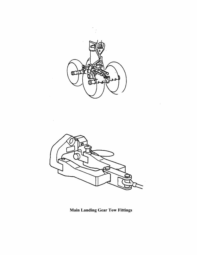
5. Towing by Main Gears (Ref. Figure 5)
Forward of rearward towing by the main landing gears uses two fork-shaped fittings and a cable. The two fittings, which are specific tools, are attached to lugs provided at each end of the. gear bogie beam.
The two fitting/cable set is provided with a safety shear pin calibrated to 29000 daN (65200 Lbf).
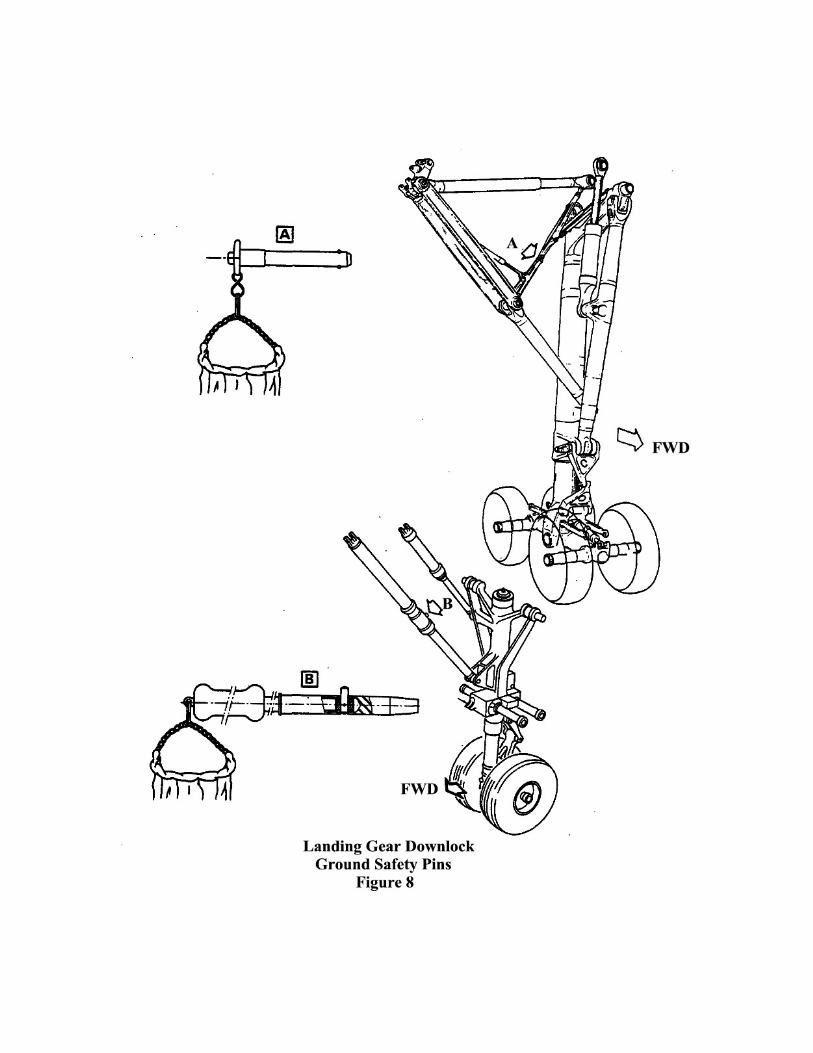
6. Landing Gear Downlock Ground Safety Pins
If required the landing gear may be mechanically locked in the "down" position during towing by inserting ground safety pins in the nose gear telescopic drag strut and in main gear locking rods (Ref. Figure 8).
A. Electrical Supply
During towing operations several aircraft systems have to be electrically supplied.
A ground power unit provided on the tractor is connected to a ground power receptacle located underneath the fuselage aft of the nose landing gear well.
Before supplying the aircraft electrical network, the Cockpit Safety Check must be performed. If necessary, the cockpit DOME Lights must be switched ON.
At night, if the anti-collision lighting is required by local airport regulations or by airlines procedures the BEACON/STROBE lighting must be turned ON.
If communication between the aircraft and the control tower is necessary the VHF communication system N° 1 must be activated.
During-the towing operation, the flight interphone system must be used providing communication between the flight compartment and the ground crew.
The ground crew boomset connection is located in the electric ground power receptacle aft of the nose landing gear well.