Embed Size (px)
Citation preview
- Accident - Serious Incident - Incident
- Accident
- Serious Incident
- Incident
AAI Case Reference: 10/2009
AIR ACCIDENT INVESTIGATION SECTOR
FINAL
AIR ACCIDENT INVESTIGATION REPORT
AIRCRAFT CRASH AFTER TAKEOFF Boeing 707-330C ST-AKW Azza Air Transport Near Sharjah International Airport The United Arab Emirates 21 October 2009
General Civil Aviation Authority of
The United Arab Emirates AAI Form 036 (November 2011)
AIR ACCIDENT FINAL REPORT 10/2009, DATED 12 March 2013 ii
Air Accident Investigation Sector General Civil Aviation Authority
United Arab Emirates
OBJECTIVE
This Investigation is performed in accordance with the UAE Federal Act No. 20 of 1991, promulgating the Civil Aviation Law, Chapter VII, Aircraft Accidents, Article 48, and in compliance with the UAE Civil Aviation Regulations, Part VI, Chapter 3, Aviation Accident and Incident Investigation, and in conformity with Annex 13 to the Convention on International Civil Aviation.
The sole objective of this Investigation is to prevent aircraft accidents and incidents. It is not the purpose of this activity to apportion blame or liability.
AIR ACCIDENT FINAL REPORT 10/2009, DATED 12 March 2013 iii
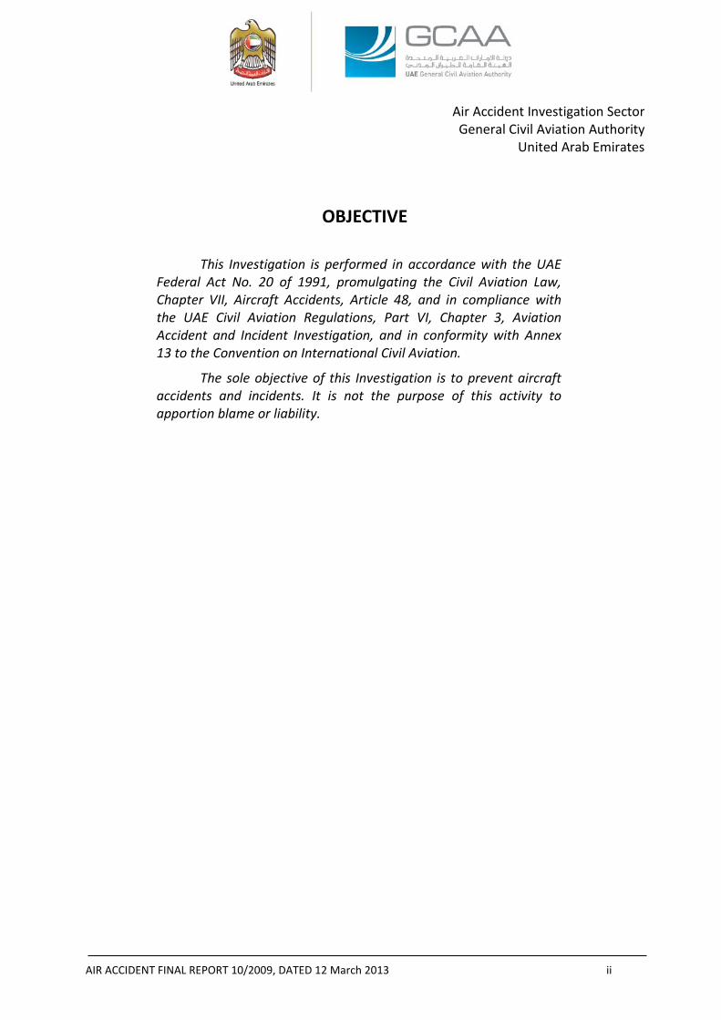
AIRCRAFT ACCIDENT BRIEF GCAA AAI Report No.: 10/2009 Operator: Azza Air Transport Aircraft Type and Registration: Boeing 707-330C (Cargo), ST-AKW Engine Type: Four, Pratt & Whitney JT3D-3B Turbofan Engines Date and Time (UTC): 21 October 2009, 1131 Location: 1.6 kilometers (0.86 nautical miles) from the end of runway 30
(threshold of RWY 12), Sharjah International Airport Type of Flight: Cargo Transport Persons on Board: 6 crewmembers Injuries: 6 Fatal Nature of Damage: Aircraft completely destroyed by ground impact and consumed by fire
The Accident, involving a Boeing 707-330C (Cargo) aircraft, registration mark ST-AKW, was notified to the General Civil Aviation Authority (“GCAA”), on 21 October 2009 at about 1133 UTC. An investigation Team was formed, launched immediately and reached the Accident site within minutes after the notification was received from Sharjah International Airport. The Investigation Team coordinated with all authorities on site by initiating the Accident Investigation process in accordance with the already developed practices and procedures. The Air Accident Investigation Sector (“AAIS”) of the GCAA led the Investigation as the United Arab Emirates (“UAE”) is the State of Occurrence. Notes:
1 The word (“Aircraft”) in this Report refers to the Accident Aircraft.
2 The word (“Airport”) in this Report refers to Sharjah International Airport, UAE.
3 Since Azza Air Transport was holding the maintenance and control functions as a “lessor” of the Aircraft to Sudan Airways “lessee”; the word “Operator” in this Report will always refer to Azza Air Transport.
4 The word (“Team”) in this Report refers to the Accident Investigation Team led by an Investigator-In-Charge (“IIC”) assigned by the GCAA and encompassed investigators from the GCAA, an Accredited Representative from Sudan Civil Aviation Authority (“SCAA”) and his Advisor, and an Accredited Representative from the National Transportation Safety Board (“NTSB”) of the United States of America (“USA”) and his Advisors from the Federal Aviation Administration (“FAA”), the Boeing Company, and Pratt & Whitney.
5 All times in this Report are Coordinated Universal Time (“UTC”) (UAE Local Time= UTC +4 hours).
6 All directional references to front and rear, right and left, top and bottom, and clockwise and counterclockwise are made aft looking forward (“ALF”) as is the convention. The direction of rotation of the engine low and high rotors is clockwise. All numbering in the circumferential direction starts with the No. 1 position at the 12:00 o’clock position, or immediately clockwise from the 12:00 o’clock position and progresses sequentially clockwise ALF.
AIR ACCIDENT FINAL REPORT 10/2009, DATED 12 March 2013 iv
7 Photos used in the text of this Report are taken from different sources and are adjusted from the original for the sole purpose to improve the clarity of the Report. Modifications to images used in this Report are limited to cropping, magnification, file compression, or enhancement of color, brightness, contrast, or addition of text boxes, arrows or lines.
AIR ACCIDENT FINAL REPORT 10/2009, DATED 12 March 2013 v
ABBREVIATIONS AND DEFINITIONS USED IN THIS REPORT
ACMI Aircraft, Crew, Maintenance and Insurance AD Airworthiness Directive AFM Airplane Flight Manual AGL Above Ground Level AMM Aircraft Maintenance Manual AMS Aircraft Maintenance Schedule An Antonov ANR Air Navigation Regulations of Sudan ANU Airplane Nose Up ATA Air Transport Association AVG Average BOAS Blade Outer Air Seal °C Degrees Centigrade (unit of temperature) CAR Civil Aviation Regulations of the UAE CAS Calibrated Air Speed CFR Code of Federal Regulations of the USA C.G. Center of Gravity C/O Carried Out CPCP Corrosion Prevention and Control Program CRS Certificate of Release to Service CVR Cockpit Voice Recorder CSN Cycles Since New CV Curriculum Vitae EASA European Aviation Safety Agency ECAM The Egyptian Company for Aircraft Maintenance EGT Exhaust Gas Temperature EPR Engine Pressure Ratio EU European Union E.W. Empty Weight EXH TEMP Exhaust Temperature (a Gauge in Pilot’s Center Panel) FCU Fuel Control Unit FDR Flight Data Recorder ft Feet FWD Forward GCAA The General Civil Aviation Authority of the United Arab
Emirates HPC High Pressure Compressor HPT High Pressure Turbine hrs Hours IAS Indicated Air Speed ICAO The International Civil Aviation Organization ID Inner Diameter
AIR ACCIDENT FINAL REPORT 10/2009, DATED 12 March 2013 vi
IIC Investigator-In-Charge IL Ilyushin IMC Intermediate Case Investigation The investigation into this Accident INBD Inboard JIC Job Instruction Card km Kilometer(s) (unit of distance) kts Knot(s) (unit of speed) LE Leading Edge LG Landing Gear LH Left Hand LOC Loss of Control LPC Low Pressure Compressor LPT Low Pressure Turbine LT Local time of the United Arab Emirates m Meters(s) (unit of distance) MAC Mean Aerodynamic Chord MAX Maximum METAR A format for reporting weather information (Aviation
Routine Weather Report) MSN Manufacturer Serial Number MIN or MNM Minimum MPD Maintenance Planning Document MLG Main Landing Gear N1 Identifies the low pressure rotor section of a turbine engine;
and its rotational speed is normally expressed as a percentage (%) of a reference speed
N2 Identifies the high pressure rotor section of a turbine engine; and its rotational speed is normally expressed as a percentage (%) of a reference speed
NLG Nose Landing Gear NS Nacelle Station (Stations referring to a certain datum
identified along the aircraft in inches) No. Number NRC Non-Routine Card NTSB The National Transportation Safety Board OAT Outside Air Temperature OD Outer Diameter OUTBD Outboard PF Pilot Flying PIC Pilot In Command P/N Part Number PNF Pilot Not Flying PPC Pilot Proficiency Check
AIR ACCIDENT FINAL REPORT 10/2009, DATED 12 March 2013 vii
Pt7 Engine exhaust total pressure Pt2 Engine inlet total pressure QNH Barometric pressure adjusted to sea level RH Right Hand RIC Routine Inspection Card RPM Revolutions Per Minute RVR Runway Visual Range RWY Runway s Second(s) (unit of time) SEM Scanning Electronic Microscope S/N Serial Number SSID Supplemental Structural Inspection Document SUD 2241 Accident flight number SCAA Sudan Civil Aviation Authority SFOD Safety and Flight Operations Directorate of the SCAA TAF Terminal Aerodrome Forecast TAS True Air Speed TCDS Type Certificate Data Sheet TE Trailing Edge TEC Turbine Exhaust Case T/R Thrust reverser TSN Time Since New (in flight hours) TWY Taxiway UAE The United Arab Emirates USOAP Universal Safety Oversight Audit Program UTC Coordinated Universal Time V/C Visual Check
AIR ACCIDENT FINAL REPORT 10/2009, DATED 12 March 2013 viii
TABLE OF CONTENTS OBJECTIVE ii
AIRCRAFT ACCIDENT BRIEF iii
ABBREVIATIONS AND DEFINITIONS USED IN THIS REPORT v
TABLE OF CONTENTS viii
SYNOPSIS xi
1. FACTUAL INFORMATION 1
1.1 HISTORY OF FLIGHT ............................................................................................ 1
1.2 INJURIES TO PERSONS ........................................................................................ 3
1.3 DAMAGE TO AIRCRAFT ....................................................................................... 3
1.4 OTHER DAMAGE ................................................................................................. 3
1.5 PERSONNEL INFORMATION ................................................................................ 3
1.5.1 The Captain .................................................................................................... 5
1.5.2 The Co-pilot ................................................................................................... 8
1.5.3 Flight Engineer ............................................................................................. 10
1.6 AIRCRAFT INFORMATION ................................................................................. 10
1.6.1 Type General Information ........................................................................... 10
1.6.2 Aircraft General Information ....................................................................... 11
1.6.3 Aircraft Maintenance History ...................................................................... 12
1.6.4 JT3D-3B Engine Description......................................................................... 16
1.6.5 Thrust Reversers Description ...................................................................... 16
1.6.6 Engine Pressure Ratio Indicating System .................................................... 17
1.7 METEOROLOGICAL INFORMATION .................................................................... 18
1.8 AIDS TO NAVIGATION ....................................................................................... 19
1.9 COMMUNICATIONS .......................................................................................... 19
1.10 AERODROME FORMATION ............................................................................... 20
1.11 FLIGHT RECORDERS .......................................................................................... 21
1.11.1 General Information .................................................................................... 21
1.11.2 Recovery of the Flight Recorders ................................................................ 21
1.11.3 CVR Examination ......................................................................................... 21
1.11.4 FDR Examination ......................................................................................... 22
AIR ACCIDENT FINAL REPORT 10/2009, DATED 12 March 2013 ix
1.11.5 Maintenance Records of the CVR and FDR ................................................. 23
1.12 WRECKAGE AND IMPACT INFORMATION .......................................................... 23
1.13 MEDICAL AND PATHOLOGICAL INFORMATION .................................................. 26
1.14 FIRE ................................................................................................................. 26
1.15 SURVIVAL ASPECTS ........................................................................................... 27
1.16 TESTS AND RESEARCH ....................................................................................... 27
1.16.1 No. 4 Engine Core Cowls Examination ........................................................ 27
1.16.2 Cowl Hinge Support Structure Examination ............................................... 30
1.16.3 Engine Instrument Panel Examination ........................................................ 31
1.16.4 Fuel Control Units Examination ................................................................... 33
1.16.5 No. 4 Engine Examination ........................................................................... 34
1.16.6 No. 4 Engine Core T/R Examination ............................................................ 35
1.16.7 Simulation with All Engines Operating and Thrust Reverser on the
“Stow” Position ........................................................................................................ 37
1.17 ORGANIZATIONAL AND MANAGEMENT INFORMATION .................................... 39
1.17.1 Operator’s Information ............................................................................... 39
1.17.2 The Operator’s Organisation Structure ....................................................... 39
1.17.3 Operator’s Maintenance Procedure ........................................................... 40
1.17.4 Operator’s Operations Procedure ............................................................... 40
1.17.6 Operator’s Crew Training Policy .................................................................. 41
1.17.7 Lease Agreement ......................................................................................... 41
1.17.8 SCAA’s Audits on the Operator ................................................................... 41
1.17.9 The Sudanese State Oversight System ........................................................ 44
1.17.10 The UAE Foreign Operators’ Oversight System ........................................... 45
1.18 ADDITIONAL INFORMATION ............................................................................. 46
1.18.1 Engine Failure and Shutdown Emergency/Abnormal Checklist .................. 46
1.18.2 Calculating the Takeoff Parameters ............................................................ 48
1.18.3 Inadvertent In-flight Reverse Thrust ........................................................... 48
1.18.4 Interviews .................................................................................................... 49
1.18.5 Annex 6 on the International Civil Aviation, Part I- Flight crew
member training programs ...................................................................................... 51
1.19 USEFUL OR EFFECTIVE INVESTIGATION TECHNIQUES ......................................... 51
2. ANALYSIS 52
2.1 NO. 4 ENGINE COWLS ....................................................................................... 52
AIR ACCIDENT FINAL REPORT 10/2009, DATED 12 March 2013 x
2.2 ENGINE PERFORMANCE .................................................................................... 53
2.3 AIRCRAFT PERFORMANCE ................................................................................. 53
2.4 CREW PERFORMANCE ...................................................................................... 55
2.5 MAINTENANCE MANAGEMENT......................................................................... 58
2.6 OPERATIONS’ MANAGEMENT ........................................................................... 59
2.7 THE SUDAN CIVIL AVIATION AUTHORITY ........................................................... 60
2.8 THE UAE FOREIGN OPERATORS’ OVERSIGHT SYSTEM ........................................ 60
3. CONCLUSIONS 61
3.1 GENERAL .......................................................................................................... 61
3.2 FINDINGS ......................................................................................................... 61
3.3 CAUSES ............................................................................................................ 62
3.4 CONTRIBUTING FACTORS TO THE ACCIDENT ..................................................... 63
4. SAFETY RECOMMENDATIONS 64
4.1 PROMPT SAFETY RECOMMENDATIONS ............................................................. 64
4.2 FINAL REPORT SAFETY RECOMMENDATIONS..................................................... 64
4.2.1 The Sudan Civil Aviation Authority ............................................................. 64
4.2.2 The Egyptian Company for Aircraft Maintenance ....................................... 65
4.2.4 The General Civil Aviation Authority of the United Arab Emirates ............ 65
PPENDIX A- JIC 15 and NRC 081 Performed in the Last C3-Check 66
APPENDIX B- RIC 05 Performed in the Last B-Check 68
APPENDIX C- Part of the Egyptian Aircraft Accident Investigation Directorate Response to the
Draft Final Report to be Appended to the Final Report 69
APPENDIX D- Pratt & Whitney Report No. 9417, Dated: 20 April 2011 72
“Sequence of Events for Sudan Airways B707 ST-AKW No. 4 Powerplant Core Thrust Reverser
Post-Impact Deployment” 72
AIR ACCIDENT FINAL REPORT 10/2009, DATED 12 March 2013 xi
SYNOPSIS On 21 October 2009, about 1131 UTC, Sudan Airways, SUD 2241, cargo Boeing 707-330,
registration mark ST-AKW, leased from Azza Air Transport, crashed about 1.6 km (0.86 nautical miles) from the end of Runway (“RWY”) 30 of Sharjah International Airport after approximately one minute from liftoff.
The Aircraft was operating a flight from Sharjah International Airport, UAE to Khartoum International Airport, Sudan, with a total of six persons onboard: three flight crewmembers (captain, co-pilot, and flight engineer), a ground engineer, and two load masters. All of the crewmembers sustained fatal injuries due to the high impact forces.
Sometime after of liftoff, the core cowls of No. 4 engine separated and collapsed onto the departure runway, consequently No. 4 Engine Pressure Ratio (“EPR”) manifold flex line ruptured leading to erroneous reading on the EPR indicator. The crew interpreted the EPR reading as a failure of No. 4 engine; accordingly they declared engine loss and requested the tower to return to the Airport.
The Aircraft went into a right turn, banked and continuously rolled to the right at a high rate, sunk, and impacted the ground with an approximately 90° right wing down attitude.
The Investigation identified the following Causes:
(a) the departure of the No. 4 engine core cowls;
(b) the consequent disconnection of No. 4 engine EPR Pt7 flex line;
(c) the probable inappropriate crew response to the perceived No. 4 engine power loss;
(d) the Aircraft entering into a stall after the published maximum bank angle was exceeded; and
(e) the Aircraft Loss of Control (“LOC”) that was not recoverable.
Contributing Factors to the Accident were:
(a) the Aircraft was not properly maintained in accordance with the Structure Repair Manual where the cowls had gone through multiple skin repairs that were not up to aviation standards;
(b) the Operator’s maintenance system failure to correctly address the issues relating to the No. 4 engine cowls failure to latch issues;
(c) the failure of the inspection and maintenance systems of the maintenance organization, which performed the last C-Check, to address, and appropriately report, the damage of the No. 4 engine cowls latches prior to issuing a Certificate of Release to Service;
(d) the Operator’s failure to provide a reporting system by which line maintenance personnel report maintenance deficiencies and receive timely and appropriate guidance and correction actions;
(e) the Operator’s quality system failure to adequately inspect and then allow repairs that were of poor quality or were incorrectly performed to continue to remain on the Aircraft; and
(f) the SCAA safety oversight system deficiency to adequately identify the Operator’s chronic maintenance, operations and quality management deficiencies.
Seven Safety Recommendations are made.
AIR ACCIDENT FINAL REPORT 10/2009, DATED 12 March 2013 1
1. FACTUAL INFORMATION
1.1 HISTORY OF FLIGHT On 21 October 2009, a Boeing 707-330C (Cargo) Aircraft, registration mark ST-AKW, called the
Sharjah International Airport tower at 11:08:45 UTC requesting engine start and pushback clearance from cargo area 60 for operating cargo flight number SUD 2241 from Sharjah International Airport, UAE, to Khartoum International Airport, Sudan, with a total of six persons onboard: three flight crew members (captain, co-pilot, and flight engineer), a ground engineer, and two load masters. The tower controller cleared SUD 2241 to start up and pushback for departure from RWY 30.
At 11:15:43, SUD 2241 contacted the tower requesting taxi clearance. The tower instructed SUD 2241 to taxi to the RWY 30 holding point via taxiways J, A and G. SUD 2241 copied the controller’s instructions correctly.
At 11:17:36, the tower requested SUD 2241 to confirm the taxi out and SUD 2241 answered that it would begin taxiing in one minute.
At 11:18:36, the tower contacted SUD 2241 cancelling the clearance to taxi and advised SUD 2241 to contact the tower when ready. SUD 2241 replied immediately that it was ready and the tower instructed them to standby.
At 11:20:07, the tower instructed SUD 2241 to taxi to RWY 30 holding point via taxiways J and A. SUD 2241 confirmed the instructions correctly.
At 11:21:58, the tower contacted SUD 2241 informing “clearance available” and advising to pass Ranbi 2M departure, maintain 3,000 feet, squawk 0532 and when airborne, switch to frequency 126.2. SUD 2241 confirmed the instructions correctly except for the squawk code, which was corrected by the tower and affirmed by SUD 2241.
At 11:26:08, the tower instructed SUD 2241 to enter RWY 30 via taxiway G, “line-up and wait”. SUD 2241 confirmed the instructions correctly.
At 11:27:20, the tower contacted SUD 2241 for one amendment to the departure instructions which was to climb on runway track to altitude 2,000. SUD 2241 confirmed the instructions correctly.
At 11:27:34, the tower reported the surface wind to SUD 2241 as of 320° 10 kts and cleared SUD 2241 for takeoff from RWY 30. SUD 2241 read back the clearance correctly.
Sometime thereafter, SUD 2241 started the takeoff and climbed normally with no further communication with the tower controller.
Approximately 15 seconds (“s”) after liftoff, when the Aircraft was approximately 300 ft Above Ground Level (“AGL”), the core cowls of the No. 4 engine detached and collapsed onto the departure runway.
At 11:29:19, SUD 2241 contacted the tower announcing that the Aircraft “was diverting back due to losing No. 4 engine”. Accordingly the tower controller pressed the ‘crash alarm’ and simultaneously informed SUD 2241 that both runways were available to land.
The crew did not respond to the tower controller. The Aircraft suddenly changed heading, banked and continuously rolled to the right at a high rate, sunk, and impacted the ground with an approximately 90° right wing down attitude. The impact was approximately 1.6 km (0.86 nautical miles) from the end of RWY 30, about one minute after liftoff.
There were no reported mechanical anomalies before departure.
The high impact forces and subsequent fire completely destroyed the Aircraft.
AIR ACCIDENT FINAL REPORT 10/2009, DATED 12 March 2013 2
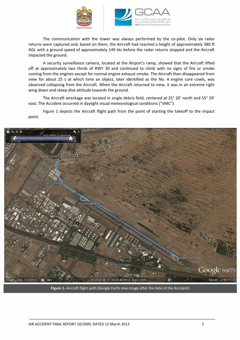
Figure 1- Aircraft flight path (Google Earth new image after the date of the Accident)
The communication with the tower was always performed by the co-pilot. Only six radar returns were captured and, based on them, the Aircraft had reached a height of approximately 380 ft AGL with a ground speed of approximately 149 kts before the radar returns stopped and the Aircraft impacted the ground.
A security surveillance camera, located at the Airport’s ramp, showed that the Aircraft lifted off at approximately two thirds of RWY 30 and continued to climb with no signs of fire or smoke coming from the engines except for normal engine exhaust smoke. The Aircraft then disappeared from view for about 25 s at which time an object, later identified as the No. 4 engine core cowls, was observed collapsing from the Aircraft. When the Aircraft returned to view, it was in an extreme right wing down and steep dive attitude towards the ground.
The Aircraft wreckage was located in single debris field, centered at 25° 20’ north and 55° 29’ east. The Accident occurred in daylight visual meteorological conditions (“VMC”).
Figure 1 depicts the Aircraft flight path from the point of starting the takeoff to the impact point.
AIR ACCIDENT FINAL REPORT 10/2009, DATED 12 March 2013 3
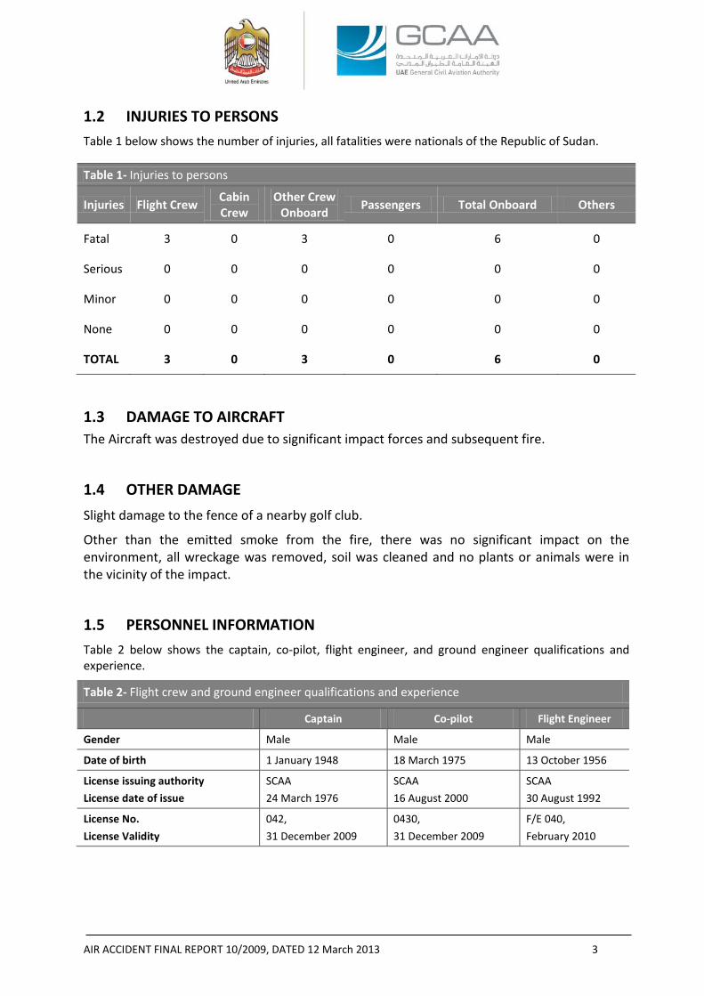
1.2 INJURIES TO PERSONS Table 1 below shows the number of injuries, all fatalities were nationals of the Republic of Sudan.
Table 1- Injuries to persons
Injuries Flight Crew Cabin Crew
Other Crew Onboard Passengers Total Onboard Others
Fatal 3 0 3 0 6 0
Serious 0 0 0 0 0 0
Minor 0 0 0 0 0 0
None 0 0 0 0 0 0
TOTAL 3 0 3 0 6 0
1.3 DAMAGE TO AIRCRAFT The Aircraft was destroyed due to significant impact forces and subsequent fire.
1.4 OTHER DAMAGE Slight damage to the fence of a nearby golf club.
Other than the emitted smoke from the fire, there was no significant impact on the environment, all wreckage was removed, soil was cleaned and no plants or animals were in the vicinity of the impact.
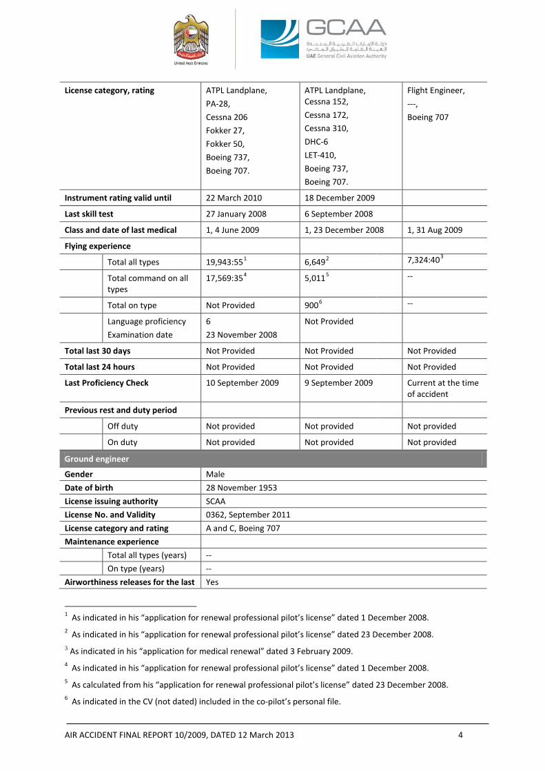
1.5 PERSONNEL INFORMATION Table 2 below shows the captain, co-pilot, flight engineer, and ground engineer qualifications and experience.
Table 2- Flight crew and ground engineer qualifications and experience
Captain Co-pilot Flight Engineer
Gender Male Male Male
Date of birth 1 January 1948 18 March 1975 13 October 1956
License issuing authority License date of issue
SCAA 24 March 1976
SCAA 16 August 2000
SCAA 30 August 1992
License No. License Validity
042, 31 December 2009
0430, 31 December 2009
F/E 040, February 2010
AIR ACCIDENT FINAL REPORT 10/2009, DATED 12 March 2013 4
License category, rating ATPL Landplane, PA-28, Cessna 206 Fokker 27, Fokker 50, Boeing 737, Boeing 707.
ATPL Landplane, Cessna 152, Cessna 172, Cessna 310, DHC-6 LET-410, Boeing 737, Boeing 707.
Flight Engineer, ---, Boeing 707
Instrument rating valid until 22 March 2010 18 December 2009
Last skill test 27 January 2008 6 September 2008
Class and date of last medical 1, 4 June 2009 1, 23 December 2008 1, 31 Aug 2009
Flying experience
Total all types 19,943:551 6,6492 7,324:403
Total command on all types
17,569:354 5,0115 --
Total on type Not Provided 9006 --
Language proficiency Examination date
6 23 November 2008
Not Provided
Total last 30 days Not Provided Not Provided Not Provided
Total last 24 hours Not Provided Not Provided Not Provided
Last Proficiency Check 10 September 2009 9 September 2009 Current at the time of accident
Previous rest and duty period
Off duty Not provided Not provided Not provided
On duty Not provided Not provided Not provided
Ground engineer
Gender Male Date of birth 28 November 1953 License issuing authority SCAA License No. and Validity 0362, September 2011 License category and rating A and C, Boeing 707 Maintenance experience Total all types (years) -- On type (years) -- Airworthiness releases for the last Yes
1 As indicated in his “application for renewal professional pilot’s license” dated 1 December 2008. 2 As indicated in his “application for renewal professional pilot’s license” dated 23 December 2008. 3 As indicated in his “application for medical renewal” dated 3 February 2009. 4 As indicated in his “application for renewal professional pilot’s license” dated 1 December 2008. 5 As calculated from his “application for renewal professional pilot’s license” dated 23 December 2008. 6 As indicated in the CV (not dated) included in the co-pilot’s personal file.
AIR ACCIDENT FINAL REPORT 10/2009, DATED 12 March 2013 5
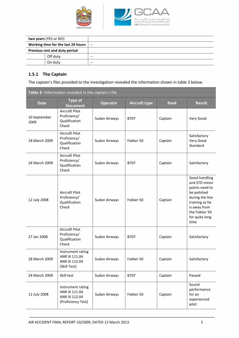
two years (YES or NO) Working time for the last 24 hours -- Previous rest and duty period Off duty -- On duty -- 1.5.1 The Captain
The captain’s files provided to the Investigation revealed the information shown in table 3 below.
Table 3- Information included in the captain’s file
Date Type of Document Operator Aircraft type Rank Result
10 September 2009
Aircraft Pilot Proficiency/ Qualification Check
Sudan Airways B707 Captain Very Good
18 March 2009
Aircraft Pilot Proficiency/ Qualification Check
Sudan Airways Fokker 50 Captain Satisfactory Very Good Standard
24 March 2009
Aircraft Pilot Proficiency/ Qualification Check
Sudan Airways B707 Captain Satisfactory
12 July 2008
Aircraft Pilot Proficiency/ Qualification Check
Sudan Airways Fokker 50 Captain
Good handling and STD minor points need to be polished during the line training as he is away from the Fokker 50 for quite long time
27 Jan 2008
Aircraft Pilot Proficiency/ Qualification Check
Sudan Airways B707 Captain Satisfactory
18 March 2009
Instrument rating ANR IX 111.04 ANR IX 112.04 (Skill Test)
Sudan Airways Fokker 50 Captain Satisfactory
24 March 2009 Skill test Sudan Airways B707 Captain Passed
12 July 2008
Instrument rating ANR IX 111.04 ANR IX 112.04 (Proficiency Test)
Sudan Airways Fokker 50 Captain
Sound performance for an experienced pilot
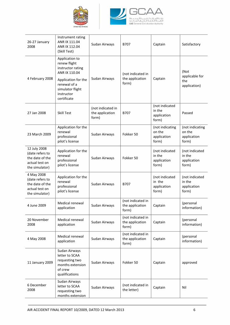
AIR ACCIDENT FINAL REPORT 10/2009, DATED 12 March 2013 6
26-27 January 2008
Instrument rating ANR IX 111.04 ANR IX 112.04 (Skill Test)
Sudan Airways B707 Captain Satisfactory
4 February 2008
Application to renew flight instructor rating ANR IX 110.04
Application for the renewal of a simulator flight instructor certificate
Sudan Airways (not indicated in the application form)
Captain
(Not applicable for the application)
27 Jan 2008 Skill Test (not indicated in the application form)
B707
(not indicated in the application form)
Passed
23 March 2009
Application for the renewal professional pilot’s license
Sudan Airways Fokker 50
(not indicating on the application form)
(not indicating on the application form)
12 July 2008 (date refers to the date of the actual test on the simulator)
Application for the renewal professional pilot’s license
Sudan Airways Fokker 50
(not indicated in the application form)
(not indicated in the application form)
4 May 2008 (date refers to the date of the actual test on the simulator)
Application for the renewal professional pilot’s license
Sudan Airways B707
(not indicated in the application form)
(not indicated in the application form)
4 June 2009 Medical renewal application Sudan Airways
(not indicated in the application form)
Captain (personal information)
20 November 2008
Medical renewal application Sudan Airways
(not indicated in the application form)
Captain (personal information)
4 May 2008 Medical renewal application Sudan Airways
(not indicated in the application form)
Captain (personal information)
11 January 2009
Sudan Airways letter to SCAA requesting two months extension of crew qualifications
Sudan Airways Fokker 50 Captain approved
6 December 2008
Sudan Airways letter to SCAA requesting two months extension
Sudan Airways (not indicated in the letter) Captain Nil
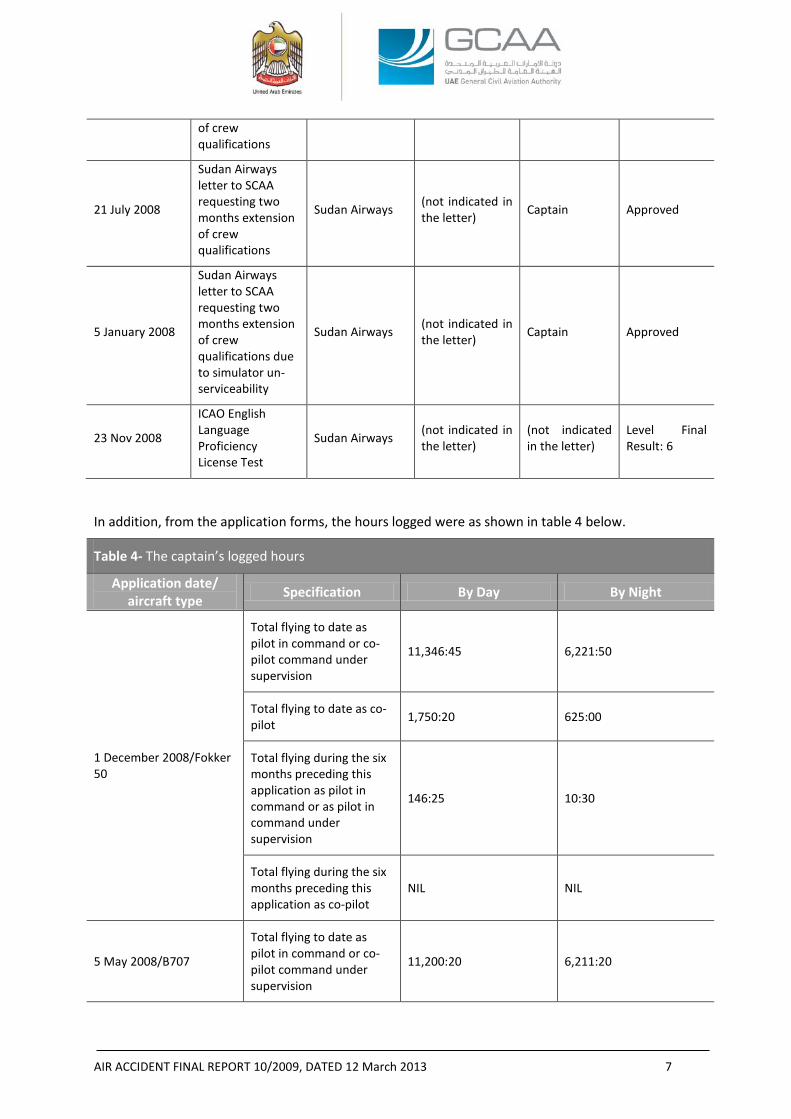
AIR ACCIDENT FINAL REPORT 10/2009, DATED 12 March 2013 7
of crew qualifications
21 July 2008
Sudan Airways letter to SCAA requesting two months extension of crew qualifications
Sudan Airways (not indicated in the letter) Captain Approved
5 January 2008
Sudan Airways letter to SCAA requesting two months extension of crew qualifications due to simulator un-serviceability
Sudan Airways (not indicated in the letter) Captain Approved
23 Nov 2008
ICAO English Language Proficiency License Test
Sudan Airways (not indicated in the letter)
(not indicated in the letter)
Level Final Result: 6
In addition, from the application forms, the hours logged were as shown in table 4 below.
Table 4- The captain’s logged hours
Application date/ aircraft type Specification By Day By Night
1 December 2008/Fokker 50
Total flying to date as pilot in command or co-pilot command under supervision
11,346:45 6,221:50
Total flying to date as co-pilot 1,750:20 625:00
Total flying during the six months preceding this application as pilot in command or as pilot in command under supervision
146:25 10:30
Total flying during the six months preceding this application as co-pilot
NIL NIL
5 May 2008/B707
Total flying to date as pilot in command or co-pilot command under supervision
11,200:20 6,211:20
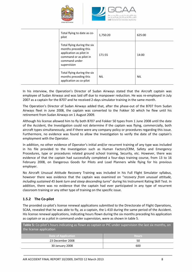
AIR ACCIDENT FINAL REPORT 10/2009, DATED 12 March 2013 8
Total flying to date as co-pilot 1,750:20 625:00
Total flying during the six months preceding this application as pilot in command or as pilot in command under supervision
171:55 14:00
Total flying during the six months preceding this application as co-pilot
NIL NIL
In his interview, the Operation’s Director of Sudan Airways stated that the Aircraft captain was employee of Sudan Airways and was laid off due to manpower reduction. He was re-employed in July 2007 as a captain for the B707 and he received 2-days simulator training in the same month.
The Operation’s Director of Sudan Airways added that, after the phase-out of the B707 from Sudan Airways fleet in June 2008, the captain was converted to the Fokker 50 which he flew until his retirement from Sudan Airways on 1 August 2009.
Although his license allowed him to fly both B707 and Fokker 50 types from 1 June 2008 until the date of the Accident, the Investigation could not determine if the captain was flying, commercially, both aircraft types simultaneously, and if there were any company policy or procedures regarding this issue. Furthermore, no evidence was found to allow the Investigation to verify the date of the captain’s employment with the Operator.
In addition, no other evidence of Operator’s initial and/or recurrent training of any type was included in his file provided to the Investigation such as Human Factors/CRM, Safety and Emergency Procedures, type or procedures related ground school training, Security, etc. However, there was evidence of that the captain had successfully completed a four-days training course, from 13 to 16 February 2008, on Dangerous Goods for Pilots and Load Planners while flying for his previous employer.
No Aircraft Unusual Attitude Recovery Training was included in his Full Flight Simulator syllabus, however there was evidence that the captain was examined on “recovery from unusual attitude, including sustained 45 bank turn and steep descending turns” during his Instrument Rating Skill Test. In addition, there was no evidence that the captain had ever participated in any type of recurrent classroom training or any other type of training on the specific issue. 1.5.2 The Co-pilot
The provided co-pilot’s license renewal applications submitted to the Directorate of Flight Operations, SCAA, revealed that he was able to fly, as a captain, the L-410 during the same period of the Accident. His license renewal applications, indicating hours flown during the six months preceding his application as captain or as a pilot in command under supervision, were as shown in table 5.
Table 5: Co-pilot’s hours indicating as flown as captain or PIC under supervision the last six months, on the license application
Date of Application Hours 23 December 2008 50
30 January 2008 600
AIR ACCIDENT FINAL REPORT 10/2009, DATED 12 March 2013 9
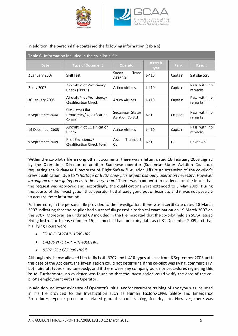
In addition, the personal file contained the following information (table 6):
Table 6- Information included in the co-pilot’s file
Date Type of Document Operator Aircraft type Rank Result
2 January 2007 Skill Test Sudan Trans ATTECO L-410 Captain Satisfactory
2 July 2007 Aircraft Pilot Proficiency Check (“PPC”) Attico Airlines L-410 Captain Pass with no
remarks
30 January 2008 Aircraft Pilot Proficiency/ Qualification Check Attico Airlines L-410 Captain Pass with no
remarks
6 September 2008 Simulator Pilot Proficiency/ Qualification Check
Sudanese States Aviation Co Ltd B707 Co-pilot Pass with no
remarks
19 December 2008 Aircraft Pilot Qualification Check Attico Airlines L-410 Captain Pass with no
remarks
9 September 2009 Pilot Proficiency/ Qualification Check Form
Azza Transport Co B707 FO unknown
Within the co-pilot’s file among other documents, there was a letter, dated 18 February 2009 signed by the Operations Director of another Sudanese operator (Sudanese States Aviation Co. Ltd.), requesting the Sudanese Directorate of Flight Safety & Aviation Affairs an extension of the co-pilot’s crew qualification, due to “shortage of B707 crew plus urgent company operation necessity. However arrangements are going on as to be, very soon.” There was hand written evidence on the letter that the request was approved and, accordingly, the qualifications were extended to 5 May 2009. During the course of the Investigation that operator had already gone out of business and it was not possible to acquire more information.
Furthermore, in the personal file provided to the Investigation, there was a certificate dated 20 March 2007 indicating that the co-pilot had successfully passed a technical examination on 19 March 2007 on the B707. Moreover, an undated CV included in the file indicated that the co-pilot held an SCAA issued Flying Instructor License number 16, his medical had an expiry date as of 31 December 2009 and that his Flying Hours were:
• “DHC 6 CAPTAIN 1500 HRS
• L-410UVP-E CAPTAIN 4000 HRS
• B707 -320 F/O 900 HRS.”
Although his license allowed him to fly both B707 and L-410 types at least from 6 September 2008 until the date of the Accident, the Investigation could not determine if the co-pilot was flying, commercially, both aircraft types simultaneously, and if there were any company policy or procedures regarding this issue. Furthermore, no evidence was found so that the Investigation could verify the date of the co-pilot’s employment with the Operator.
In addition, no other evidence of Operator’s initial and/or recurrent training of any type was included in his file provided to the Investigation such as Human Factors/CRM, Safety and Emergency Procedures, type or procedures related ground school training, Security, etc. However, there was
AIR ACCIDENT FINAL REPORT 10/2009, DATED 12 March 2013 10
evidence of that the co-pilot had successfully completed a three-days training course, from to 29 April to 1 May 2008, on Dangerous Goods for Pilots and Load Planners from another operator.
No Aircraft Unusual Attitude Recovery Training was included in his Full Flight Simulator syllabus, however there was evidence that the co-pilot was examined on “recovery from unusual attitude, including sustained 45 bank turn and steep descending turns” during his Instrument Rating Skill Test. In addition, there was no evidence that the co-pilot had ever participated in any type of recurrent classroom training or any other type of training on the specific issue. 1.5.3 Flight Engineer
From the provided information to the Investigation, the flight engineer was trained by another operator on the B707 systems from 10 to 22 October 1988, B707 General Familiarisation course from 29 July to 16 August 1980, trainee Engineer from May 1987 to April 1988, maintenance course from 22 October to 19 November 1983, and later trained by Egypt Air on a conversion course for pilots & flight engineers from 3 to 30 October 1990. His provided file included proficiency checks, skill tests, and medical renewal applications which all showed ”satisfactory” results. In addition, there was evidence included in the provided information showing that the flight engineer was granted “authorisation” to provide training on B707.
Furthermore, his license was validated by the Transport and Communications Department of Aviation of Aruba on 21 March 1997 for one year. No other ground related training pertinent to Human Factors/CRM, Safety and Emergency Procedures, type or procedures related ground school training, Security, was made available to the Investigation. However, there was evidence of that the flight engineer had successfully completed a three-days training course, from 29 April to 1 May 2008, on Dangerous Goods for Pilots and Load Planners from another operator. Moreover, no Aircraft Unusual Attitude Recovery Training was included in his Full Flight Simulator syllabus, there was no evidence that the flight engineer ever participated in any type of recurrent classroom training nor any other type of training on the specific issue.
1.6 AIRCRAFT INFORMATION
1.6.1 Type General Information
The Boeing 707-300C series was type certificated under Type Certificate Data Sheet (“TCDS”) No. 4A26, approved on 30 April 1963 with the latest amendment dated 30 July 1984, in accordance with Part 4b “Airplane Airworthiness Transport Categories”7 of the Civil Air Regulations promulgated by the Civil Aeronautical Board of the United States.
The Boeing 707-330C cockpit is configured with three basic flight crew members encompassing the captain, co-pilot, and flight engineer seats with one observer seat.
The thrust levers are located at the top front of the central pedestal.
The flight instruments are located on the captain and co-pilot panels, overhead panel, flight engineer upper and front panels, and aft panel located on the central pedestal.
The engine instruments are located on the Engine Instrument Panel between the two pilots’ instrument panels. The EPR gauges are located above the N1 and N2 gauges.
7 Civil Air Regulations Part 4b was the historical regulations of the USA for the Airplane Airworthiness- Transport Category before the Part 25 “Airworthiness Standards: Transport Category Airplanes” of CFR 14 takes place.
AIR ACCIDENT FINAL REPORT 10/2009, DATED 12 March 2013 11
1.6.2 Aircraft General Information
The Aircraft was a Boeing 707-330C, narrow body, cargo configuration, equipped with four Pratt & Whitney JT3D-3B turbofan engines, first delivered as a passenger aircraft to Lufthansa in February 1969 and was the 788th B707 manufactured off the Boeing line (MSN 20123).
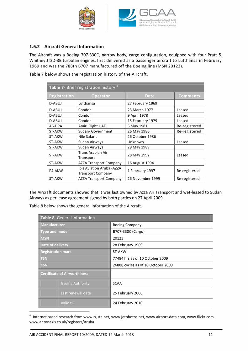
Table 7 below shows the registration history of the Aircraft.
Table 7- Brief registration history 8
Registration Operator Date Comments
D-ABUJ Lufthansa 27 February 1969 D-ABUJ Condor 23 March 1977 Leased D-ABUJ Condor 9 April 1978 Leased D-ABUJ Condor 15 February 1979 Leased A6-DPA Amiri Flight UAE 5 May 1981 Re-registered ST-AKW Sudan- Government 26 May 1986 Re-registered ST-AKW Nile Safaris 26 October 1986 ST-AKW Sudan Airways Unknown Leased ST-AKW Sudan Airways 29 May 1989
ST-AKW Trans Arabian Air Transport 28 May 1992 Leased
ST-AKW AZZA Transport Company 16 August 1994
P4-AKW Ibis Aviation Aruba -AZZA Transport Company 1 February 1997 Re-registered
ST-AKW AZZA Transport Company 26 November 1999 Re-registered
The Aircraft documents showed that it was last owned by Azza Air Transport and wet-leased to Sudan Airways as per lease agreement signed by both parties on 27 April 2009.
Table 8 below shows the general information of the Aircraft.
Table 8- General information
Manufacturer Boeing Company
Type and model B707-330C (Cargo)
MSN 20123
Date of delivery 28 February 1969
Registration mark ST-AKW
TSN 77484 hrs as of 10 October 2009
CSN 26888 cycles as of 10 October 2009
Certificate of Airworthiness
Issuing Authority SCAA
Last renewal date 25 February 2008
Valid till 24 February 2010
8 Internet based research from www.rzjsta.net, www.jetphotos.net, www.airport-data.com, www.flickr.com, www.antonakis.co.uk/registers/Aruba.
AIR ACCIDENT FINAL REPORT 10/2009, DATED 12 March 2013 12
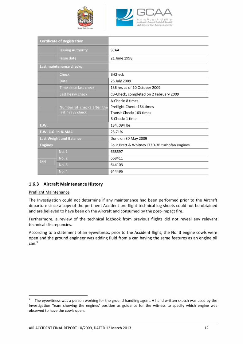
Certificate of Registration
Issuing Authority SCAA
Issue date 21 June 1998
Last maintenance checks
Check B-Check
Date 25 July 2009
Time since last check 136 hrs as of 10 October 2009
Last heavy check C3-Check, completed on 2 February 2009
Number of checks after the last heavy check
A-Check: 8 times Preflight Check: 164 times Transit Check: 163 times B-Check: 1 time
E.W. 134, 094 lbs
E.W. C.G. in % MAC 25.71%
Last Weight and Balance Done on 30 May 2009
Engines Four Pratt & Whitney JT3D-3B turbofan engines
S/N
No. 1 668597
No. 2 668411
No. 3 644103
No. 4 644495
1.6.3 Aircraft Maintenance History
Preflight Maintenance
The Investigation could not determine if any maintenance had been performed prior to the Aircraft departure since a copy of the pertinent Accident pre-flight technical log sheets could not be obtained and are believed to have been on the Aircraft and consumed by the post-impact fire.
Furthermore, a review of the technical logbook from previous flights did not reveal any relevant technical discrepancies.
According to a statement of an eyewitness, prior to the Accident flight, the No. 3 engine cowls were open and the ground engineer was adding fluid from a can having the same features as an engine oil can.9
9 The eyewitness was a person working for the ground handling agent. A hand written sketch was used by the Investigation Team showing the engines’ position as guidance for the witness to specify which engine was observed to have the cowls open.
AIR ACCIDENT FINAL REPORT 10/2009, DATED 12 March 2013 13
Instrument Reading Log
The Investigation reviewed the Operator’s Instrument Reading Log10 back to 4 February 2009 up to the date of the Accident. Within that time period, the following were noticed:
- Engine power ratings were set at Reduced Takeoff Power in most of the logged flights.
- With all the engines N1 and N2 matched, the No. 3 engine displayed higher EPRs and EGT values.
- There were no reported engine in-flight shutdowns.
Approved Maintenance Schedule (“AMS”)
The AMS No. AZ/AMS/01 was approved by letter No. CAA/7/AW/ENO/AZZA AIR/B.707, dated 4 September 2008, issued by the Airworthiness Directorate of the SCAA.
According to the AMS, Revision F, dated September 2008; a Pre-flight Check was to be performed prior to the first flight of the day; a Transit Check was to be performed prior to every flight; and A-, B- and C-Checks were to be performed not to exceed 30 days, 120 ± 15 days, and 12 ± 3 months, respectively.
The A-Check provides for an inspection of the powerplants and airframe including some lubrication and system checks.
The B-Check provides for an inspection of the Aircraft and its systems.
The C-Check combines the requirement of the A- and B-Checks plus additional items required to ensure a complete structural airframe and system inspection to complete checks within a period not exceeding 5 years calendar time.
In addition to the above checks, Structural Inspections are to be performed according to Boeing Document D6-7552, Supplemental Structural Inspection Document (“SSID”) according to Boeing Document D6-44860, and Corrosion and Aging Inspections according to Documents D6-54928 and D6-54996, respectively. Last C3-Check
Due to the fact that the No. 4 engine cowls had departed the Aircraft shortly after takeoff and the pilot had reported No. 4 engine loss, the Investigation focused its attention on any maintenance record entries pertaining to the No. 4 engine, its cowlings, or Thrust Reverser (“T/R”).11
After the last C3-Check, a Certificate of Release to Service (“CRS”) was issued on 2 February 2009 by the Egyptian Company for Aircraft Maintenance (“ECAM”)12 showing that, in addition to the C3-Check tasks, maintenance tasks were performed in accordance with the Corrosion Prevention and Control Program (“CPCP”), Airworthiness Directives (“ADs”), and Non-Routine Cards (“NRCs”) generated from the Job Instruction Cards (“JICs”) as listed in the Routine Cards Index prepared by ECAM as an equivalent document to the work order submitted by the Operator to ECAM that contained the Operator’s Routine Inspection Cards (“RICs”).
10 “Instrument Reading Log” is a log used by the Operator to record engines’ parameters, during cruise, such as the EGT, EPR, N1, N2, etc. 11 The T/R review was triggered due to that the No. 4 engine T/R was found at the deploy position at the Accident site. The Investigation wanted to know whether the deploy was pre- or post- impact (refer to figure 8). 12 ECAM place of maintenance facilities is in Sharm El-Sheikh, Egypt. A maintenance contract agreement No. ECAM/AZZA Company/001/B707-30C was signed by the Operator and ECAM in August 2008. A term related to the last C3-Check was contained in that agreement.
AIR ACCIDENT FINAL REPORT 10/2009, DATED 12 March 2013 14
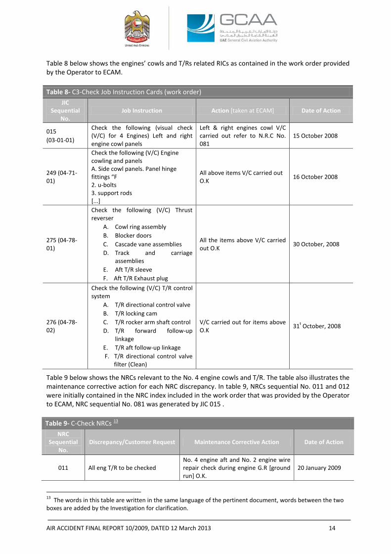
Table 8 below shows the engines’ cowls and T/Rs related RICs as contained in the work order provided by the Operator to ECAM. Table 8- C3-Check Job Instruction Cards (work order)
JIC Sequential
No. Job Instruction Action [taken at ECAM] Date of Action
015 (03-01-01)
Check the following (visual check (V/C) for 4 Engines) Left and right engine cowl panels
Left & right engines cowl V/C carried out refer to N.R.C No. 081
15 October 2008
249 (04-71-01)
Check the following (V/C) Engine cowling and panels A. Side cowl panels. Panel hinge fittings “F 2. u-bolts 3. support rods [...]
All above items V/C carried out O.K 16 October 2008
275 (04-78-01)
Check the following (V/C) Thrust reverser
A. Cowl ring assembly B. Blocker doors C. Cascade vane assemblies D. Track and carriage
assemblies E. Aft T/R sleeve F. Aft T/R Exhaust plug
All the items above V/C carried out O.K 30 October, 2008
276 (04-78-02)
Check the following (V/C) T/R control system
A. T/R directional control valve B. T/R locking cam C. T/R rocker arm shaft control D. T/R forward follow-up
linkage E. T/R aft follow-up linkage F. T/R directional control valve
filter (Clean)
V/C carried out for items above O.K 31t October, 2008
Table 9 below shows the NRCs relevant to the No. 4 engine cowls and T/R. The table also illustrates the maintenance corrective action for each NRC discrepancy. In table 9, NRCs sequential No. 011 and 012 were initially contained in the NRC index included in the work order that was provided by the Operator to ECAM, NRC sequential No. 081 was generated by JIC 015 . Table 9- C-Check NRCs 13
NRC Sequential
No. Discrepancy/Customer Request Maintenance Corrective Action Date of Action
011 All eng T/R to be checked No. 4 engine aft and No. 2 engine wire repair check during engine G.R [ground run] O.K.
20 January 2009
13 The words in this table are written in the same language of the pertinent document, words between the two boxes are added by the Investigation for clarification.
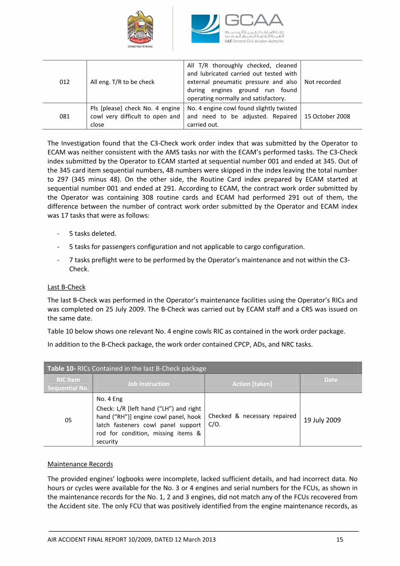
AIR ACCIDENT FINAL REPORT 10/2009, DATED 12 March 2013 15
012 All eng. T/R to be check
All T/R thoroughly checked, cleaned and lubricated carried out tested with external pneumatic pressure and also during engines ground run found operating normally and satisfactory.
Not recorded
081 Pls [please] check No. 4 engine cowl very difficult to open and close
No. 4 engine cowl found slightly twisted and need to be adjusted. Repaired carried out.
15 October 2008
The Investigation found that the C3-Check work order index that was submitted by the Operator to ECAM was neither consistent with the AMS tasks nor with the ECAM’s performed tasks. The C3-Check index submitted by the Operator to ECAM started at sequential number 001 and ended at 345. Out of the 345 card item sequential numbers, 48 numbers were skipped in the index leaving the total number to 297 (345 minus 48). On the other side, the Routine Card index prepared by ECAM started at sequential number 001 and ended at 291. According to ECAM, the contract work order submitted by the Operator was containing 308 routine cards and ECAM had performed 291 out of them, the difference between the number of contract work order submitted by the Operator and ECAM index was 17 tasks that were as follows:
- 5 tasks deleted.
- 5 tasks for passengers configuration and not applicable to cargo configuration.
- 7 tasks preflight were to be performed by the Operator’s maintenance and not within the C3-Check.
Last B-Check
The last B-Check was performed in the Operator’s maintenance facilities using the Operator’s RICs and was completed on 25 July 2009. The B-Check was carried out by ECAM staff and a CRS was issued on the same date.
Table 10 below shows one relevant No. 4 engine cowls RIC as contained in the work order package.
In addition to the B-Check package, the work order contained CPCP, ADs, and NRC tasks.
Table 10- RICs Contained in the last B-Check package
RIC Item Sequential No. Job Instruction Action [taken] Date
05
No. 4 Eng Check: L/R [left hand (“LH”) and right hand (“RH”)] engine cowl panel, hook latch fasteners cowl panel support rod for condition, missing items & security
Checked & necessary repaired C/O. 19 July 2009
Maintenance Records
The provided engines’ logbooks were incomplete, lacked sufficient details, and had incorrect data. No hours or cycles were available for the No. 3 or 4 engines and serial numbers for the FCUs, as shown in the maintenance records for the No. 1, 2 and 3 engines, did not match any of the FCUs recovered from the Accident site. The only FCU that was positively identified from the engine maintenance records, as
AIR ACCIDENT FINAL REPORT 10/2009, DATED 12 March 2013 16
belonging to a particular engine, was the No. 4 engine FCU. As another example, the S/N for the 1st stage fan disk for the No. 1 engine did not match that of the disk recovered in the wreckage. Weight and Balance
The Accident flight Loadsheet & Loadmessage All Cargo Aircraft documents showed that the takeoff weight was 131,505 kg (289,919 pounds) including 24,000 kg (52,911 pounds) trip fuel. The C.G. location was 28% and the maximum takeoff weight of the Aircraft was 136,032 kg (299,899 pounds). Although the Investigation found that, as shown by the loadsheet, the takeoff weight was below the maximum takeoff weight, the Investigation could not verify the maximum takeoff weight limitation from the provided Airplane Flight Manual (“AFM”). 1.6.4 JT3D-3B Engine Description
The JT3D-3B engine is a dual-spool, axial flow, low bypass ratio, turbofan engine having a multistage split compressor, an eight can (can-annular) combustion chamber, and a split four-stage reaction-impulse turbine.
The front compressor contains two fan stages and six Low Pressure Compressor (“LPC”) stages. The rear compressor contains seven High Pressure Compressor (“HPC”) stages. Stage numbering convention in the compressor section is as follows: the fan stages are stages 1 and 2, the LPC stages are 4 to 9 and the HPC stages are 10 to 16. There is no stage designated as stage 3 in the compressor.
The High Pressure Turbine (“HPT”) is a single-stage turbine that drives the rear compressor through the HPT drive shaft. The Low Pressure Turbine (“LPT”) is a three-stage turbine that drives the front compressor through the LPT drive shaft. Stage numbering convention in the turbine section is as follows: the HPT is stage 1 and the LPT is stages 2 to 4. Together the fan, LPC, and LPT are considered the low (“N1”) rotor, while the HPC and HPT are considered the high (“N2”) rotor.
An accessory gearbox, driven by the engine high rotor through a towershaft, has provisions for, among other things, the engine main fuel pump, hydro-mechanical fuel control unit, aircraft hydraulic pump, air turbine starter, and an alternator. The engine is flat-rated14 to 84 °F (28.8 °C) and has a maximum thrust of 18,000 pounds.
A nacelle provides an aerodynamic fairing around the outside of the engine. The nacelle consists of an inlet cowl, LH and RH fan cowl, LH and RH engine core cowl, and an aft thrust reverser outer sleeve. The fan and engine cowls are hinged at the top to the aircraft pylon and latch on the bottom of the engine and are capable of being opened for the purpose of performing maintenance on the engine. 1.6.5 Thrust Reversers Description
The JT3D engine is equipped with a T/R that consists of a fan T/R and a core exhaust T/R. The fan T/R components are located circumferentially around the front compressor fan case. During forward thrust operation, the exhaust air from the fan discharge of the front compressor is discharged through ducting surrounding the engine. During reverse thrust operation, the pneumatic fan T/R actuators move the cowl ring aft and positions the blocker doors into the fan discharge redirecting the flow through lower vane assemblies and baffle assemblies in a forward direction.
The core T/R is attached to the Turbine Exhaust Case (“TEC”) and during forward thrust operation is part of the intermediate path for exhaust gas flow between the engine and tail pipe. During reverser operation, the pneumatic core T/R actuators move the translating sleeve rearward uncovering cascade
14 Flat-rated to a specific temperature indicates that the engine is capable of producing the rated power up to the specific inlet temperature.
AIR ACCIDENT FINAL REPORT 10/2009, DATED 12 March 2013 17
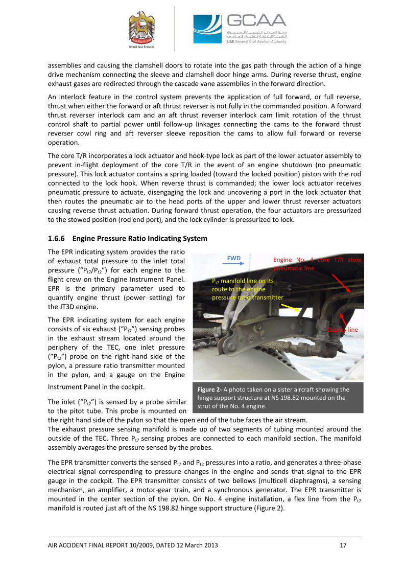
Engine No. 4 core T/R stow pneumatic line
Deploy line
Pt7 manifold line on its route to the engine pressure ratio transmitter
Figure 2- A photo taken on a sister aircraft showing the hinge support structure at NS 198.82 mounted on the strut of the No. 4 engine.
assemblies and causing the clamshell doors to rotate into the gas path through the action of a hinge drive mechanism connecting the sleeve and clamshell door hinge arms. During reverse thrust, engine exhaust gases are redirected through the cascade vane assemblies in the forward direction.
An interlock feature in the control system prevents the application of full forward, or full reverse, thrust when either the forward or aft thrust reverser is not fully in the commanded position. A forward thrust reverser interlock cam and an aft thrust reverser interlock cam limit rotation of the thrust control shaft to partial power until follow-up linkages connecting the cams to the forward thrust reverser cowl ring and aft reverser sleeve reposition the cams to allow full forward or reverse operation.
The core T/R incorporates a lock actuator and hook-type lock as part of the lower actuator assembly to prevent in-flight deployment of the core T/R in the event of an engine shutdown (no pneumatic pressure). This lock actuator contains a spring loaded (toward the locked position) piston with the rod connected to the lock hook. When reverse thrust is commanded; the lower lock actuator receives pneumatic pressure to actuate, disengaging the lock and uncovering a port in the lock actuator that then routes the pneumatic air to the head ports of the upper and lower thrust reverser actuators causing reverse thrust actuation. During forward thrust operation, the four actuators are pressurized to the stowed position (rod end port), and the lock cylinder is pressurized to lock. 1.6.6 Engine Pressure Ratio Indicating System
The EPR indicating system provides the ratio of exhaust total pressure to the inlet total pressure (“Pt7/Pt2”) for each engine to the flight crew on the Engine Instrument Panel. EPR is the primary parameter used to quantify engine thrust (power setting) for the JT3D engine.
The EPR indicating system for each engine consists of six exhaust (“Pt7”) sensing probes in the exhaust stream located around the periphery of the TEC, one inlet pressure (“Pt2”) probe on the right hand side of the pylon, a pressure ratio transmitter mounted in the pylon, and a gauge on the Engine
Instrument Panel in the cockpit.
The inlet (“Pt2”) is sensed by a probe similar to the pitot tube. This probe is mounted on the right hand side of the pylon so that the open end of the tube faces the air stream. The exhaust pressure sensing manifold is made up of two segments of tubing mounted around the outside of the TEC. Three Pt7 sensing probes are connected to each manifold section. The manifold assembly averages the pressure sensed by the probes.
The EPR transmitter converts the sensed Pt7 and Pt2 pressures into a ratio, and generates a three-phase electrical signal corresponding to pressure changes in the engine and sends that signal to the EPR gauge in the cockpit. The EPR transmitter consists of two bellows (multicell diaphragms), a sensing mechanism, an amplifier, a motor-gear train, and a synchronous generator. The EPR transmitter is mounted in the center section of the pylon. On No. 4 engine installation, a flex line from the Pt7 manifold is routed just aft of the NS 198.82 hinge support structure (Figure 2).
FWD
AIR ACCIDENT FINAL REPORT 10/2009, DATED 12 March 2013 18
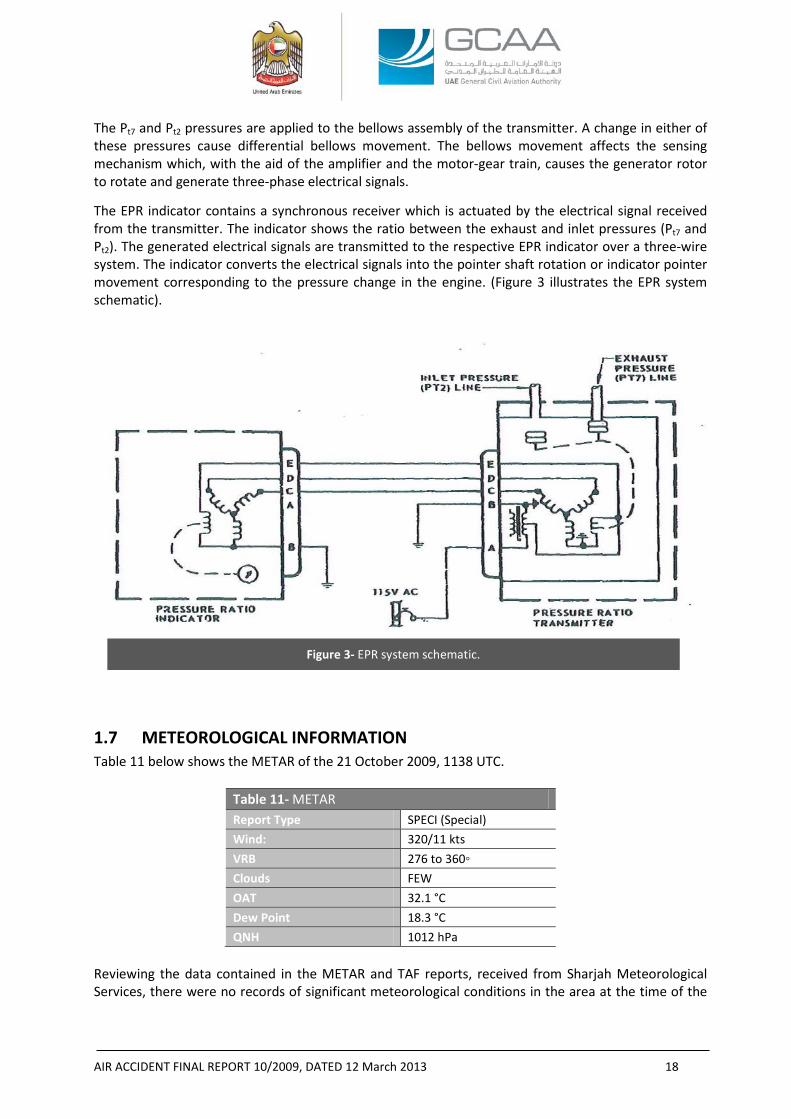
Figure 3- EPR system schematic.
The Pt7 and Pt2 pressures are applied to the bellows assembly of the transmitter. A change in either of these pressures cause differential bellows movement. The bellows movement affects the sensing mechanism which, with the aid of the amplifier and the motor-gear train, causes the generator rotor to rotate and generate three-phase electrical signals.
The EPR indicator contains a synchronous receiver which is actuated by the electrical signal received from the transmitter. The indicator shows the ratio between the exhaust and inlet pressures (Pt7 and Pt2). The generated electrical signals are transmitted to the respective EPR indicator over a three-wire system. The indicator converts the electrical signals into the pointer shaft rotation or indicator pointer movement corresponding to the pressure change in the engine. (Figure 3 illustrates the EPR system schematic).
1.7 METEOROLOGICAL INFORMATION Table 11 below shows the METAR of the 21 October 2009, 1138 UTC.
Table 11- METAR Report Type SPECI (Special) Wind: 320/11 kts VRB 276 to 360◦ Clouds FEW OAT 32.1 °C Dew Point 18.3 °C QNH 1012 hPa
Reviewing the data contained in the METAR and TAF reports, received from Sharjah Meteorological Services, there were no records of significant meteorological conditions in the area at the time of the
AIR ACCIDENT FINAL REPORT 10/2009, DATED 12 March 2013 19
Accident. Additionally, no pilot reports indicating any significant meteorological events were transmitted.
1.8 AIDS TO NAVIGATION Not a factor.
1.9 COMMUNICATIONS The ATC recordings showed that the communications between the Aircraft and the tower were clear during the entire flight.
The communication was split into three phases with two different tower controllers: the first phase started at 11:08:50 when the co-pilot requested startup and pushback clearance until the instructions were given to stop and hold at the runway holding point. That phase lasted for 1 minute 22 s. The second phase started at 11:27:34 when takeoff clearance was given by the tower and ended when the co-pilot said “have a good day” to the controller, that phase lasted for 1 minute 18 s. The third phase started at 1:29:19 when the co-pilot informed the tower of his intention to return to the Airport after the “perceived“ No. 4 engine loss and ended when the controller repeated twice “you are clear to land both runways”. That phase lasted for 10 s.
The silent period between the second and third phases was approximately 1 minute 38 s during which the Aircraft took off and climbed until the co-pilot reported “engine loss”.
Since there was a time difference between the time stamps of the ATC transcript and the clock time on the Airport security surveillance video, an attempt was made to match and resolve the time difference between the two using definite and known events captured by both in addition to time calculations for the takeoff, the cowls separation, and the declared engine loss.
The ATC transcript showed that the period from the co-pilot’s takeoff clearance confirmation to the time of declaring No. 4 engine loss was 1 minute 38 s. Assuming that it took the crew 2 s from the time they perceived engine loss to the time of No. 4 engine loss declaration; the time from the co-pilot’s takeoff clearance confirmation to the declaration would be 1 minute 36 s (1 minute 38 s minus 2 s).
The following assumptions were made for the purpose of time calculations:
1. Three possible takeoff roll periods until reaching approximately 20 m (65 ft) AGL were taken: 45, 55, and 65 s.
2. The cowls had separated 2 s before their first appearance in the security surveillance video camera.
3. The takeoff roll had started 7 s after the co-pilot confirmed the takeoff clearance to the tower controller.
Table 12 below shows the main events and their respective times from the time of takeoff clearance to the time of engine No. 4 loss declaration.
Table 12- Time sequence of the main events from the takeoff until engine loss announcement
1 2 3 4 5 T/O time duration a Starting roll (ATC time) b 20 m AGL (ATC time) Cowl separation
(ATC time) Engine loss Declaration
(ATC time)
00:01:05 11:27:48 11:28:53 11:29:05 11:29:19
AIR ACCIDENT FINAL REPORT 10/2009, DATED 12 March 2013 20
00:00:55 11:27:48 11:28:43 11:28:55 11:29:19
00:00:45 11:27:48 11:28:33 11:28:45 11:29:19 a Time period in hh:mm:ss b Time in UTC
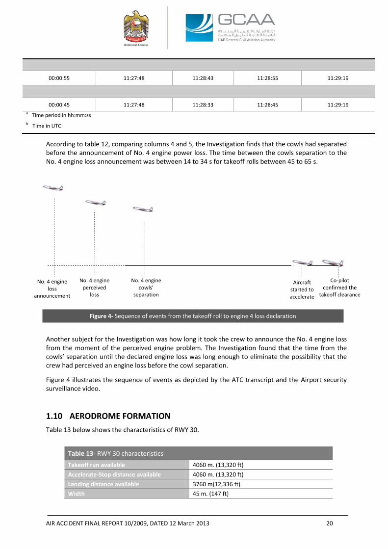
According to table 12, comparing columns 4 and 5, the Investigation finds that the cowls had separated before the announcement of No. 4 engine power loss. The time between the cowls separation to the No. 4 engine loss announcement was between 14 to 34 s for takeoff rolls between 45 to 65 s.
Another subject for the Investigation was how long it took the crew to announce the No. 4 engine loss from the moment of the perceived engine problem. The Investigation found that the time from the cowls’ separation until the declared engine loss was long enough to eliminate the possibility that the crew had perceived an engine loss before the cowl separation.
Figure 4 illustrates the sequence of events as depicted by the ATC transcript and the Airport security surveillance video.
1.10 AERODROME FORMATION Table 13 below shows the characteristics of RWY 30.
Table 13- RWY 30 characteristics Takeoff run available 4060 m. (13,320 ft) Accelerate-Stop distance available 4060 m. (13,320 ft) Landing distance available 3760 m(12,336 ft) Width 45 m. (147 ft)
Co-pilot confirmed the
takeoff clearance
Aircraft started to accelerate
No. 4 engine cowls’
separation
No. 4 engine perceived
loss
No. 4 engine loss
announcement
Figure 4- Sequence of events from the takeoff roll to engine 4 loss declaration
AIR ACCIDENT FINAL REPORT 10/2009, DATED 12 March 2013 21
The last runway inspection, that was performed before the Aircraft takeoff, did not reveal any foreign objects at the runway. Three uneventful takeoffs were conducted before the Accident Aircraft.
1.11 FLIGHT RECORDERS15
1.11.1 General Information16
The Aircraft was equipped with a Sundstrand Data Control, Inc. model FA-542 (300-hour scratch metal foil tape) Flight Data Recorder (“FDR”), P/N 101035-1, S/N 1598, and a Fairchild model A100A (30-minute continuous tape) Cockpit Voice Recorder (“CVR”), P/N 93-A100-80, S/N 54853.
The FDR system provides automatic recording of four parameters (altitude, airspeed, heading and vertical acceleration) as a function of time. A solenoid actuated scribe is provided to record coded trip, date, and event information; a second one resolves the heading ambiguity which exists when the airplane is on a 0° or 180° heading, and a third one scribes a reference time base line. The recording tape travels at a controlled rate to provide another time base for the recorded information. The recording unit, which contains a preloaded tape magazine, receives the required flight information and transcribes it in graphical form on foil tape. The recording medium is a metal foil. The tape has a row of sprockets holes, spaced two minutes apart, at each outer edge. The tape supply is sufficient for 800 hrs of recording time, 400 hrs on each side, at a rate of one-half foot per hour.
The FDR system is controlled through its power supply only. Operation of the entire recorder system is automatic, once electrical power is supplied to the system. The flight recorder switch on the pilot overhead panel completes the power circuit when ON. Parallel to this power switch are relay contacts that close on lift off; thus, assuring recorder operation even if the power switch is OFF. 1.11.2 Recovery of the Flight Recorders
The CVR was recovered on the day of the Accident, separated from the Aircraft while the FDR was recovered two days later at its normally installed position in the tail of the aircraft. Both recorders sustained extensive impact and fire damage. 1.11.3 CVR Examination
Externally, the CVR displayed extensive impact damage, partial fire damage, and sooting. The outside cover was cut off the unit to gain access to the inside crash case and the tape storage reel.
The crash case was intact but showed evidence of fire and smoke damage.
15 Both flight recorders were sent for examination to the Air Accidents Investigation Branch (“AAIB”) of the United Kingdom on 2 November 2009. Reference AAIB Internal Report No. EW/B2009/10/03. 16 Reference AMM 34-14-01.
Magnetic variation 1.3°E. Threshold elevations from sea level 116 ft (35 m)
RWY slope Variable at the whole length from 0.62% to 0.07%. 1.3°E.
RWY pavement Asphalt covering with 300 m. (984 ft) Concrete surfacing at the threshold.
AIR ACCIDENT FINAL REPORT 10/2009, DATED 12 March 2013 22
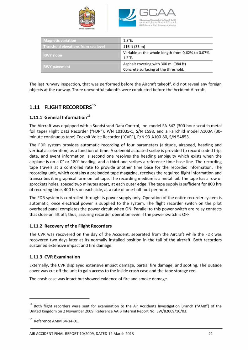
Figure 5- CVR tape ends
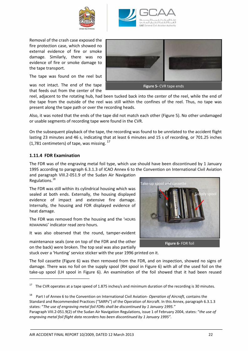
Figure 6- FDR foil
Removal of the crash case exposed the fire protection case, which showed no external evidence of fire or smoke damage. Similarly, there was no evidence of fire or smoke damage to the tape transport.
The tape was found on the reel but
was not intact. The end of the tape that feeds out from the center of the reel, adjacent to the rotating hub, had been tucked back into the center of the reel, while the end of the tape from the outside of the reel was still within the confines of the reel. Thus, no tape was present along the tape path or over the recording heads.
Also, it was noted that the ends of the tape did not match each other (Figure 5). No other undamaged or usable segments of recording tape were found in the CVR.
On the subsequent playback of the tape, the recording was found to be unrelated to the accident flight lasting 23 minutes and 46 s, indicating that at least 6 minutes and 15 s of recording, or 701.25 inches (1,781 centimeters) of tape, was missing. 17 1.11.4 FDR Examination
The FDR was of the engraving metal foil type, which use should have been discontinued by 1 January 1995 according to paragraph 6.3.1.3 of ICAO Annex 6 to the Convention on International Civil Aviation and paragraph VIII.2-051.9 of the Sudan Air Navigation Regulations.18
The FDR was still within its cylindrical housing which was sealed at both ends. Externally, the housing displayed evidence of impact and extensive fire damage. Internally, the housing and FDR displayed evidence of heat damage. The FDR was removed from the housing and the ‘HOURS REMAINING’ indicator read zero hours.
It was also observed that the round, tamper-evident
maintenance seals (one on top of the FDR and the other on the back) were broken. The top seal was also partially stuck over a ‘Hunting’ service sticker with the year 1996 printed on it.
The foil cassette (Figure 6) was then removed from the FDR, and on inspection, showed no signs of damage. There was no foil on the supply spool (RH spool in Figure 6) with all of the used foil on the take-up spool (LH spool in Figure 6). An examination of the foil showed that it had been reused 17 The CVR operates at a tape speed of 1.875 inches/s and minimum duration of the recording is 30 minutes. 18 Part I of Annex 6 to the Convention on International Civil Aviation- Operation of Aircraft, contains the Standard and Recommended Practices (“SARPs”) of the Operation of Aircraft. In this Annex, paragraph 6.3.1.3 states: “The use of engraving metal foil FDRs shall be discontinued by 1 January 1995.” Paragraph VIII.2-051.9(2) of the Sudan Air Navigation Regulations, issue 1 of February 2004, states: “the use of engraving metal foil flight data recorders has been discontinued by 1 January 1995”.
Take-up spool and cassette
Supply spool
AIR ACCIDENT FINAL REPORT 10/2009, DATED 12 March 2013 23
numerous times. Given that all of the foil was located on the take-up spool, it is very unlikely that the FDR was recording at the time of the accident. 1.11.5 Maintenance Records of the CVR and FDR
According to Annex 6 to the Convention on International Civil Aviation, paragraph 6.3.12, the Operator should have established a system to check the continued serviceability for the FDR and CVR through pre-determined operational checks.19
There was no CVR or FDR items listed in the Start, Taxi, or Before Takeoff Operations checklists.
According to the AMS, the only Preflight/Transit Operational Check item pertinent to the flight recorder was MPD No. 2-0608, underwater beacon locator unit (if installed). However there was no evidence nor verification of whether the related actual check was performed.
The AMS contained two RICs pertinent to the flight recorders which were also listed in the work order submitted by the Operator to ECAM:
- RIC No. 04-23-12 (RIC sequential No. 083 in the work order equivalent to JIC sequential No. 079 in the ECAM’s Routine Cards index) to check (Visual and Operational Check) the voice recorder System A. Installation. The ECAM’s maintenance action was “voice recorder system checked ok and the battery valid to date 2010”, the date of entry was 22 October 2008.
- RIC No. 04-34-05 (RIC sequential No. 194 in the work order equivalent to JIC sequential No. 17xx in the ECAM’s Routine Cards index) to check the following (Visual check).[...] B. Flight Recorder (Operational Check). The ECAM’s maintenance action was “OP/C [Operational Check] carried out satisfactory”, the date of entry was 22 October 2008.
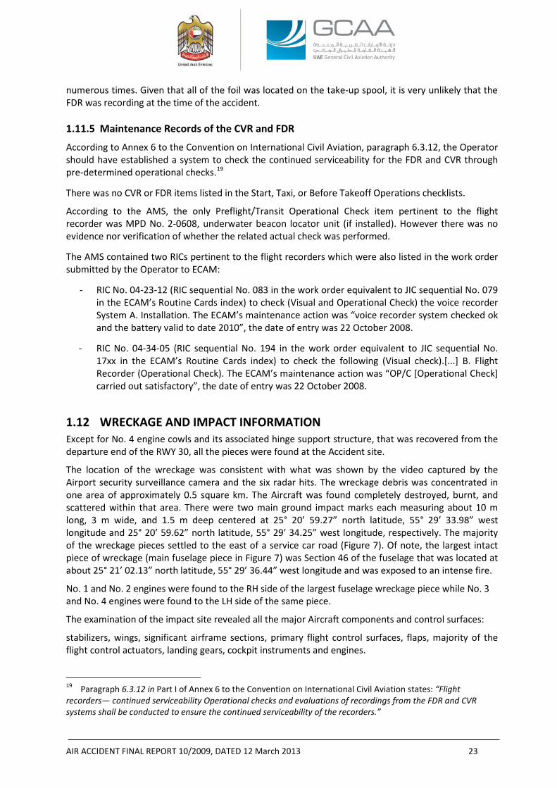
1.12 WRECKAGE AND IMPACT INFORMATION Except for No. 4 engine cowls and its associated hinge support structure, that was recovered from the departure end of the RWY 30, all the pieces were found at the Accident site.
The location of the wreckage was consistent with what was shown by the video captured by the Airport security surveillance camera and the six radar hits. The wreckage debris was concentrated in one area of approximately 0.5 square km. The Aircraft was found completely destroyed, burnt, and scattered within that area. There were two main ground impact marks each measuring about 10 m long, 3 m wide, and 1.5 m deep centered at 25° 20’ 59.27” north latitude, 55° 29’ 33.98” west longitude and 25° 20’ 59.62” north latitude, 55° 29’ 34.25” west longitude, respectively. The majority of the wreckage pieces settled to the east of a service car road (Figure 7). Of note, the largest intact piece of wreckage (main fuselage piece in Figure 7) was Section 46 of the fuselage that was located at about 25° 21’ 02.13” north latitude, 55° 29’ 36.44” west longitude and was exposed to an intense fire.
No. 1 and No. 2 engines were found to the RH side of the largest fuselage wreckage piece while No. 3 and No. 4 engines were found to the LH side of the same piece.
The examination of the impact site revealed all the major Aircraft components and control surfaces:
stabilizers, wings, significant airframe sections, primary flight control surfaces, flaps, majority of the flight control actuators, landing gears, cockpit instruments and engines.
19 Paragraph 6.3.12 in Part I of Annex 6 to the Convention on International Civil Aviation states: “Flight recorders— continued serviceability Operational checks and evaluations of recordings from the FDR and CVR systems shall be conducted to ensure the continued serviceability of the recorders.”
AIR ACCIDENT FINAL REPORT 10/2009, DATED 12 March 2013 24
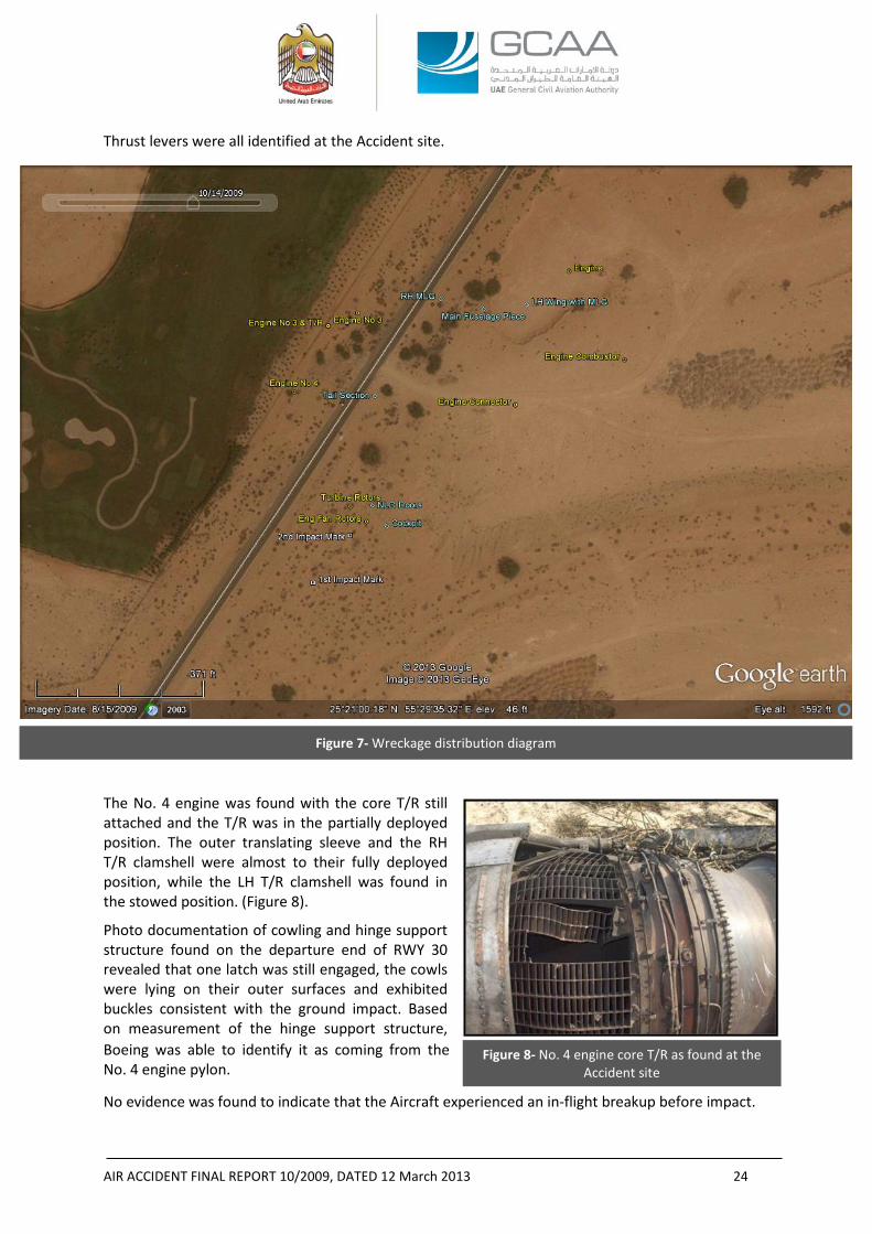
Figure 8- No. 4 engine core T/R as found at the Accident site
Thrust levers were all identified at the Accident site.
The No. 4 engine was found with the core T/R still attached and the T/R was in the partially deployed position. The outer translating sleeve and the RH T/R clamshell were almost to their fully deployed position, while the LH T/R clamshell was found in the stowed position. (Figure 8).
Photo documentation of cowling and hinge support structure found on the departure end of RWY 30 revealed that one latch was still engaged, the cowls were lying on their outer surfaces and exhibited buckles consistent with the ground impact. Based on measurement of the hinge support structure, Boeing was able to identify it as coming from the No. 4 engine pylon.
No evidence was found to indicate that the Aircraft experienced an in-flight breakup before impact.
Figure 7- Wreckage distribution diagram
AIR ACCIDENT FINAL REPORT 10/2009, DATED 12 March 2013 25
With the on-site wreckage examination complete, the wreckage was transferred to a dedicated area inside the Sharjah International Airport perimeter on 26 October 2009. Heavy cranes and trucks, supplied by the local police, were used to transport the wreckage.
After the wreckage was relocated, the NTSB Accredited Representative and his Advisors as well as the Accredited Representative of the SCAA and his Advisor arrived in the UAE and joined the GCAA Team during the period from 5 to 14 December 2009 to examine the wreckage.
Detailed field examination of the relocated wreckage revealed the following:
- LE flaps and slats: 26 of 42 leaing edge (“LE”) flaps and slat actuators were recovered, all were found to be in the extend position, the rods broken from the actuator, or the actuator housing missing from the clamping blocks.
- Nine of 10 trailing edge (“TE”) flaps transmission ballscrews were recovered. From the ballscrews measurements, the flap setting was determined to be at Flaps 14, which was consistent with takeoff configuration.
- The measurement of the stabilizer trim ballscrew indicated that the stabilizer trim was set to about 4.5° stabilizer trim LE DOWN or airplane nose up (“ANU”).
- The nose landing gear (“NLG”) and main landing gears (“MLG”) were found in the retracted position with the lock link locked in the retracted position.
The wheels and tires on the RH MLG were damaged and the damage was consistent with a post impact fire.
The tires on the LH MLG were still inflated except for the FWD-INBD tire. That tire exhibited a crown puncture consistent with having occurred post-crash with the tire in an unloaded or non-spinning state when the puncture occurred. Examination of the landing gear compartment found no traces of rubber debris or tire chunks.
- The elevators, rudder, horizontal, and vertical stabilizers were detached at different locations and were damaged by post impact fire.
- A large portion of the left wing was found intact. The right wing was heavily damaged and highly fragmented consistent with right wing down Aircraft impact.
- The four engines were impact damaged and fragmented. The compressors were exposed and the nacelle structure was detached. The accessories were detached and some (e.g. the fuel control units (“FCU”)) were recovered loose within the wreckage field. Some of the recovered hardware exhibited varying degrees of fire damage.
All the engines were identified by comparing the S/Ns of the exposed compressor disks against those recorded in the engine maintenance records.
The No. 1 engine was found in three major pieces: fan case and LPC module, HPC/diffuser area, and combustor/turbine area The HPC, HPT, and LPT rotating hardware was found separated from the remainder of the engine and was distributed in the wreckage field. The fan disks were found in the wreckage field separated from the remainder of the engine.
The No. 2 engine was complete from the LPC rear hub through to the TEC. The fan disks were found in the wreckage field separated from the remainder of the engine. The fan case and LPC module were found separated from the engine as a unit. All of the engine cases were buckled axially. The majority of the externals, ancillary components, and nacelle were separated from the engine.
The No. 3 engine was complete from the center body of the IMC through to the FWD 3-inches from the TEC. The fan disks were found in the wreckage field separated from the remainder of
AIR ACCIDENT FINAL REPORT 10/2009, DATED 12 March 2013 26
the engine. The fan case and LPC module were found separated from the engine as a unit. The sheet metal piece that connects the intermediate case (“IMC”) to the diffuser case was separated exposing the entire HPC.
For engines No. 1, 2, and 3, damage identified to airfoils within each engine was consistent with high speed rotational damage at impact.
The No. 4 engine was the least damaged engine amongst the four. The engine was complete from the front of the HPC aft. The fan disks were found in the wreckage field separated from the remainder of the engine. The fan case and LPC module were found separated from the engine as a unit. None of the cases from the diffuser case back to the TEC exhibited any breaches or indications of external fire. The majority of the externals, ancillary components, and nacelle (with the exception of the core thrust reverser) were separated from the engine. Both the first and second stage disks were intact and some blade slots were empty; however, those blades that remained were all fractured transversely at or near the blade platform and blades with some airfoil material remaining were bent in the direction opposite of rotation. The entire LPC could not be examined in-situ: however what was visible of the LPC revealed that all visible blade slots of the 6-9th stages disks were empty, had blades fractured at the platforms, or had full length blades that were bent in the direction opposite rotation. All the stator vanes that were visible were bent in the direction of rotation and exhibited trailing edge damage.
The fan reverser hardware had separated from each of the engines and, except for the No. 4 engine, all the core T/R’s had separated from the engines as well. Unlike the core T/Rs, it was not possible to associate any of the identified fan T/R hardware with any specific engine. As previously mentioned, the No. 4 engine core T/R was found partially deployed with tears, dents, and impact damage to the translating outer sleeve and clamshells along with fractured T/R actuating mechanism (Figure 7). To understand whether the T/R deployed prior to or as a consequence of the ground impact, the engine, with the T/R still attached, was shipped to a facility in the United States for a detailed examination under the oversight of the IIC.
- The No. 1, 2, and 3 engine core T/Rs sustained substantial impact damage and because of the severity of the damage it was not possible to positively identify the position of each at the time of impact, although there was no physical evidence indicating that they had deployed in-flight. Unlike the core T/R of the No. 4 engine, the three other T/R’s were not shipped for further evaluation.
- All four FCUs were found lose within the wreckage site. Comparing the S/Ns on the FCU data plates with those recorded in the engine maintenance records, only one FCU, that of the No. 4 engine, could be positively identified. The S/Ns on the other three FCUs did not match those recorded in the engine maintenance records for any of the other engines
1.13 MEDICAL AND PATHOLOGICAL INFORMATION The toxicology testing that was performed on the collected samples of the crewmembers did not reveal psychoactive substances that might have affected the performance of the crew. No other medical related information was provided to the Investigation.
1.14 FIRE None of the video captured by the Airport security surveillance camera, eyewitnesses’ reports, or the fire damage exhibited by the wreckage was consistent with an in-flight fire. The evidence was
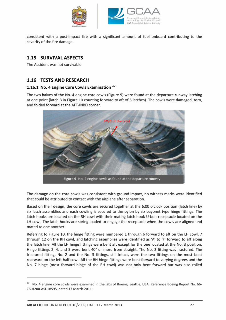
AIR ACCIDENT FINAL REPORT 10/2009, DATED 12 March 2013 27
Figure 9- No. 4 engine cowls as found at the departure runway
consistent with a post-impact fire with a significant amount of fuel onboard contributing to the severity of the fire damage.
1.15 SURVIVAL ASPECTS The Accident was not survivable.
1.16 TESTS AND RESEARCH 1.16.1 No. 4 Engine Core Cowls Examination 20
The two halves of the No. 4 engine core cowls (Figure 9) were found at the departure runway latching at one point (latch B in Figure 10 counting forward to aft of 6 latches). The cowls were damaged, torn, and folded forward at the AFT-INBD corner.
The damage on the core cowls was consistent with ground impact, no witness marks were identified that could be attributed to contact with the airplane after separation.
Based on their design, the core cowls are secured together at the 6:00 o’clock position (latch line) by six latch assemblies and each cowling is secured to the pylon by six bayonet type hinge fittings. The latch hooks are located on the RH cowl with their mating latch hook U-bolt receptacle located on the LH cowl. The latch hooks are spring loaded to engage the receptacle when the cowls are aligned and mated to one another.
Referring to Figure 10, the hinge fitting were numbered 1 through 6 forward to aft on the LH cowl, 7 through 12 on the RH cowl, and latching assemblies were identified as ‘A’ to ‘F’ forward to aft along the latch line. All the LH hinge fittings were bent aft except for the one located at the No. 3 position. Hinge fittings 2, 4, and 5 were bent 40° or more from straight. The No. 2 fitting was fractured. The fractured fitting, No. 2 and the No. 5 fittings, still intact, were the two fittings on the most bent rearward on the left half cowl. All the RH hinge fittings were bent forward to varying degrees and the No. 7 hinge (most forward hinge of the RH cowl) was not only bent forward but was also rolled
20 No. 4 engine core cowls were examined in the labs of Boeing, Seattle, USA. Reference Boeing Report No. 66-ZB-H200-ASI-18595, dated 17 March 2011.
FWD of the cowl
AIR ACCIDENT FINAL REPORT 10/2009, DATED 12 March 2013 28
forward with part of the attachment structure being torn away from the cowl with the hinge prior to full disengagement.
Along the LH core cowl latch line, the majority of the U-bolt receptacles and alignment pins were deformed. Two of the U-bolt receptacles, located at locations ‘E’ and ‘F’ were pulled-out from the hinge line with part of their fixing longeron support structure. The torn-out U-bolt receptacles remained engaged with the latch hooks on the RH core cowl.
Along the RH core cowl latch line, several of the latches had lost their spring load.
Multiple indentations and secondary hole were noted on the RH cowl hinge line flange in the vicinity of the guide pin hole consistent with the guide pin on the LH cowl being misaligned when the cowling doors were closed and latched. The number of misalignment pin marks was consistent with repetitive engagement problems and the deformations of both the alignments pins and the alignment pin receptacles confirmed this. The Investigation could not determine if all the cowl alignment pins and latches were properly engaged prior to takeoff on the Accident flight.
Additionally, numerous skin repairs to both cowls were noted that were not performed to typical aviation standards. The repairs shown in figures 11A and 11B were examples of these repairs. Figures 11C and 11D illustrate examples of indents caused by the alignment pin of the LH cowl on areas next to the pin receptacles on the RH cowl due to repetitive improper engagements.
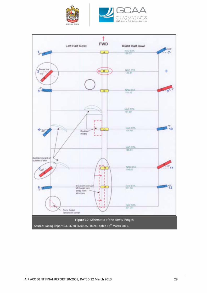
AIR ACCIDENT FINAL REPORT 10/2009, DATED 12 March 2013 29
Figure 10- Schematic of the cowls’ hinges
Source: Boeing Report No. 66-ZB-H200-ASI-18595, dated 17th March 2011.
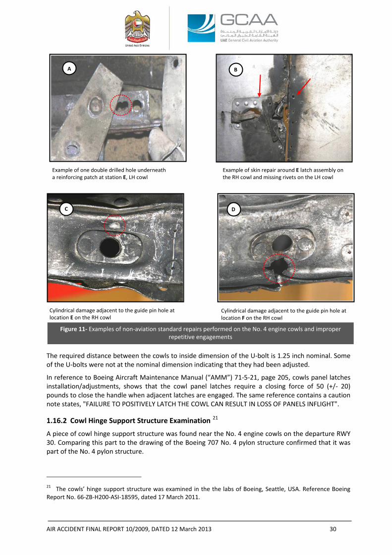
AIR ACCIDENT FINAL REPORT 10/2009, DATED 12 March 2013 30
The required distance between the cowls to inside dimension of the U-bolt is 1.25 inch nominal. Some of the U-bolts were not at the nominal dimension indicating that they had been adjusted.
In reference to Boeing Aircraft Maintenance Manual (“AMM”) 71-5-21, page 205, cowls panel latches installation/adjustments, shows that the cowl panel latches require a closing force of 50 (+/- 20) pounds to close the handle when adjacent latches are engaged. The same reference contains a caution note states, "FAILURE TO POSITIVELY LATCH THE COWL CAN RESULT IN LOSS OF PANELS INFLIGHT". 1.16.2 Cowl Hinge Support Structure Examination 21
A piece of cowl hinge support structure was found near the No. 4 engine cowls on the departure RWY 30. Comparing this part to the drawing of the Boeing 707 No. 4 pylon structure confirmed that it was part of the No. 4 pylon structure.
21 The cowls’ hinge support structure was examined in the the labs of Boeing, Seattle, USA. Reference Boeing Report No. 66-ZB-H200-ASI-18595, dated 17 March 2011.
Example of one double drilled hole underneath a reinforcing patch at station E, LH cowl
Example of skin repair around E latch assembly on the RH cowl and missing rivets on the LH cowl
Figure 11- Examples of non-aviation standard repairs performed on the No. 4 engine cowls and improper repetitive engagements
Cylindrical damage adjacent to the guide pin hole at location E on the RH cowl
Cylindrical damage adjacent to the guide pin hole at location F on the RH cowl
A B
C D
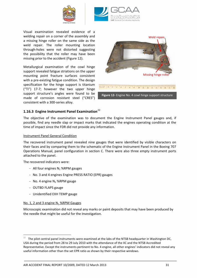
AIR ACCIDENT FINAL REPORT 10/2009, DATED 12 March 2013 31
Figure 12- Engine No. 4 cowl hinge support structure
Visual examination revealed evidence of a welding repair on a corner of the assembly and a missing hinge roller on the same side as the weld repair. The roller mounting location through-holes were not distorted suggesting the possibility that the roller may have been missing prior to the accident (Figure 12).
Metallurgical examination of the cowl hinge support revealed fatigue striations on the upper mounting point fracture surfaces consistent with a pre-existing fatigue condition. The design specification for the hinge support is titanium (“Ti”) 17-7; however the two upper hinge support structure’s angles were found to be made of corrosion resistant steel (“CRES”) consistent with a 300-series alloy. 1.16.3 Engine Instrument Panel Examination22
The objective of the examination was to document the Engine Instrument Panel gauges and, if possible, find any needle slap or impact marks that indicated the engines operating condition at the time of impact since the FDR did not provide any information.
Instrument Panel General Condition
The recovered instrument panel revealed nine gauges that were identified by visible characters on their faces and by comparing them to the schematic of the Engine Instrument Panel in the Boeing 707 Operations Manual, panel configuration in section C. There were also three empty instrument ports attached to the panel.
The recovered indicators were:
- All four engines N1 %RPM gauges
- No. 3 and 4 engines Engine PRESS RATIO (EPR) gauges
- No. 4 engine N2 %RPM gauge
- OUTBD FLAPS gauge
- Unidentified EXH TEMP gauge
No. 1, 2 and 3 engine N1 %RPM Gauges
Microscopic examination did not reveal any marks or paint deposits that may have been produced by the needle that might be useful for the Investigation.
22 The pilot central panel instruments were examined at the labs of the NTSB headquarter in Washington DC, USA during the period from 28 to 29 July 2010 with the attendance of the IIC and the NTSB Accredited Representative. Except the instruments pertinent to No. 4 engine, all other engines’ indicators did not reveal any useful information other than the set EPR ratio as shown by their respective windows.
Missing hinge roller
Weld repair
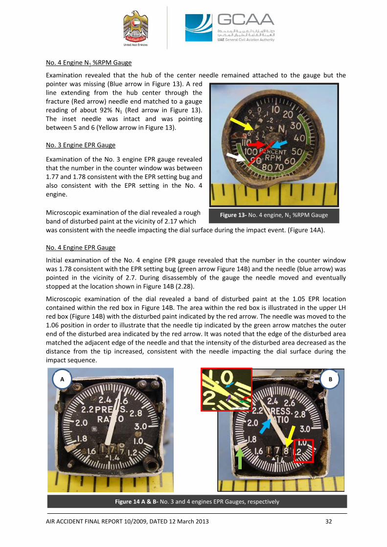
AIR ACCIDENT FINAL REPORT 10/2009, DATED 12 March 2013 32
Figure 13- No. 4 engine, N1 %RPM Gauge
No. 4 Engine N1 %RPM Gauge
Examination revealed that the hub of the center needle remained attached to the gauge but the pointer was missing (Blue arrow in Figure 13). A red line extending from the hub center through the fracture (Red arrow) needle end matched to a gauge reading of about 92% N1 (Red arrow in Figure 13). The inset needle was intact and was pointing between 5 and 6 (Yellow arrow in Figure 13). No. 3 Engine EPR Gauge
Examination of the No. 3 engine EPR gauge revealed that the number in the counter window was between 1.77 and 1.78 consistent with the EPR setting bug and also consistent with the EPR setting in the No. 4 engine.
Microscopic examination of the dial revealed a rough band of disturbed paint at the vicinity of 2.17 which was consistent with the needle impacting the dial surface during the impact event. (Figure 14A). No. 4 Engine EPR Gauge
Initial examination of the No. 4 engine EPR gauge revealed that the number in the counter window was 1.78 consistent with the EPR setting bug (green arrow Figure 14B) and the needle (blue arrow) was pointed in the vicinity of 2.7. During disassembly of the gauge the needle moved and eventually stopped at the location shown in Figure 14B (2.28).
Microscopic examination of the dial revealed a band of disturbed paint at the 1.05 EPR location contained within the red box in Figure 14B. The area within the red box is illustrated in the upper LH red box (Figure 14B) with the disturbed paint indicated by the red arrow. The needle was moved to the 1.06 position in order to illustrate that the needle tip indicated by the green arrow matches the outer end of the disturbed area indicated by the red arrow. It was noted that the edge of the disturbed area matched the adjacent edge of the needle and that the intensity of the disturbed area decreased as the distance from the tip increased, consistent with the needle impacting the dial surface during the impact sequence.
Figure 14 A & B- No. 3 and 4 engines EPR Gauges, respectively
A B
AIR ACCIDENT FINAL REPORT 10/2009, DATED 12 March 2013 33
No. 4 Engine N2 %RPM Gauge
Examination of the dial revealed no marks or paint deposits that may have been produced by the needle impacting the dial. OUTBD FLAPS Gauge
Microscopic examination of the dial revealed three distinct marks located in what could be the path of the needle’s tip. The marks were in the vicinity of 20° indication which was not consistent with the flap transmission ballscrews recovered at flaps 14 position and determined to be considered more reliable source of data thus the clue of the ballscrews overwhelmed the 20° indication marked by the OUTBD FLAPS Gauge. EXH TEMP Gauge
The Microscopic examination of the unidentified EXH TEMP gauge dial revealed no marks or paint deposits that may have been produced by the needle impacting the dial. 1.16.4 Fuel Control Units Examination23
The objective of the examination was to document any findings that could be used to determine each engines power setting at the time of impact. FCUs General Condition
Table 14 below shows the four FCUs identification:
Table 14- FCUs identification
Model Number JFC25-20 JFC25-20 JFC25-20 JFC25-20
Part Number 711286-55 711286-53 711286-9 711286-24
Serial Number 24082 66854 46218 82149
Position Unknown Unknown Unknown 4
All the FCUs exhibited damage consistent with the ground impact. The internal parts of the FCUs were intact with no noted distress that could be attributed to a pre-impact malfunction. Examinations Observations
The only finding in the units that could be considered outside of a normal service condition was the existence of loose particulates on the fuel filter of the S/N 82149 unit. Despite the particulates, the filter screen was not collapsed and the filter did not appear to be clogged to the point where engine operation would have been adversely affected. 23 The four FCUs were examined at the labs of the NTSB in Washington DC, USA during the period from 28 to 29 July 2010 with the attendance of the IIC, the NTSB Accredited Representative, and Advisors from Boeing, Hamilton Sundstrand and Pratt & Whitney. At the time of design and manufacture, Hamilton Sundstrand was known as Hamilton Standard.
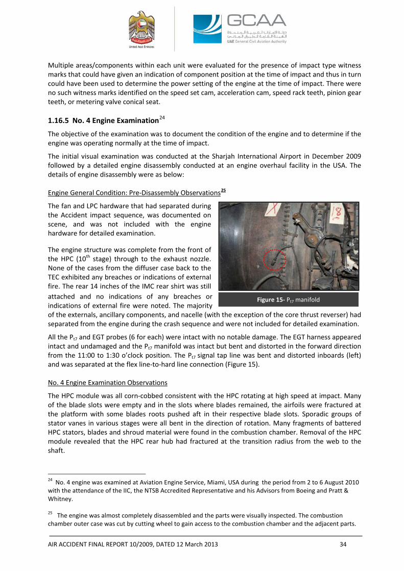
AIR ACCIDENT FINAL REPORT 10/2009, DATED 12 March 2013 34
Multiple areas/components within each unit were evaluated for the presence of impact type witness marks that could have given an indication of component position at the time of impact and thus in turn could have been used to determine the power setting of the engine at the time of impact. There were no such witness marks identified on the speed set cam, acceleration cam, speed rack teeth, pinion gear teeth, or metering valve conical seat. 1.16.5 No. 4 Engine Examination24
The objective of the examination was to document the condition of the engine and to determine if the engine was operating normally at the time of impact.
The initial visual examination was conducted at the Sharjah International Airport in December 2009 followed by a detailed engine disassembly conducted at an engine overhaul facility in the USA. The details of engine disassembly were as below: Engine General Condition: Pre-Disassembly Observations25
The fan and LPC hardware that had separated during the Accident impact sequence, was documented on scene, and was not included with the engine hardware for detailed examination.
The engine structure was complete from the front of the HPC (10th stage) through to the exhaust nozzle. None of the cases from the diffuser case back to the TEC exhibited any breaches or indications of external fire. The rear 14 inches of the IMC rear shirt was still attached and no indications of any breaches or indications of external fire were noted. The majority of the externals, ancillary components, and nacelle (with the exception of the core thrust reverser) had separated from the engine during the crash sequence and were not included for detailed examination. All the Pt7 and EGT probes (6 for each) were intact with no notable damage. The EGT harness appeared intact and undamaged and the Pt7 manifold was intact but bent and distorted in the forward direction from the 11:00 to 1:30 o’clock position. The Pt7 signal tap line was bent and distorted inboards (left) and was separated at the flex line-to-hard line connection (Figure 15). No. 4 Engine Examination Observations
The HPC module was all corn-cobbed consistent with the HPC rotating at high speed at impact. Many of the blade slots were empty and in the slots where blades remained, the airfoils were fractured at the platform with some blades roots pushed aft in their respective blade slots. Sporadic groups of stator vanes in various stages were all bent in the direction of rotation. Many fragments of battered HPC stators, blades and shroud material were found in the combustion chamber. Removal of the HPC module revealed that the HPC rear hub had fractured at the transition radius from the web to the shaft.
24 No. 4 engine was examined at Aviation Engine Service, Miami, USA during the period from 2 to 6 August 2010 with the attendance of the IIC, the NTSB Accredited Representative and his Advisors from Boeing and Pratt & Whitney. 25 The engine was almost completely disassembled and the parts were visually inspected. The combustion chamber outer case was cut by cutting wheel to gain access to the combustion chamber and the adjacent parts.
Figure 15- Pt7 manifold
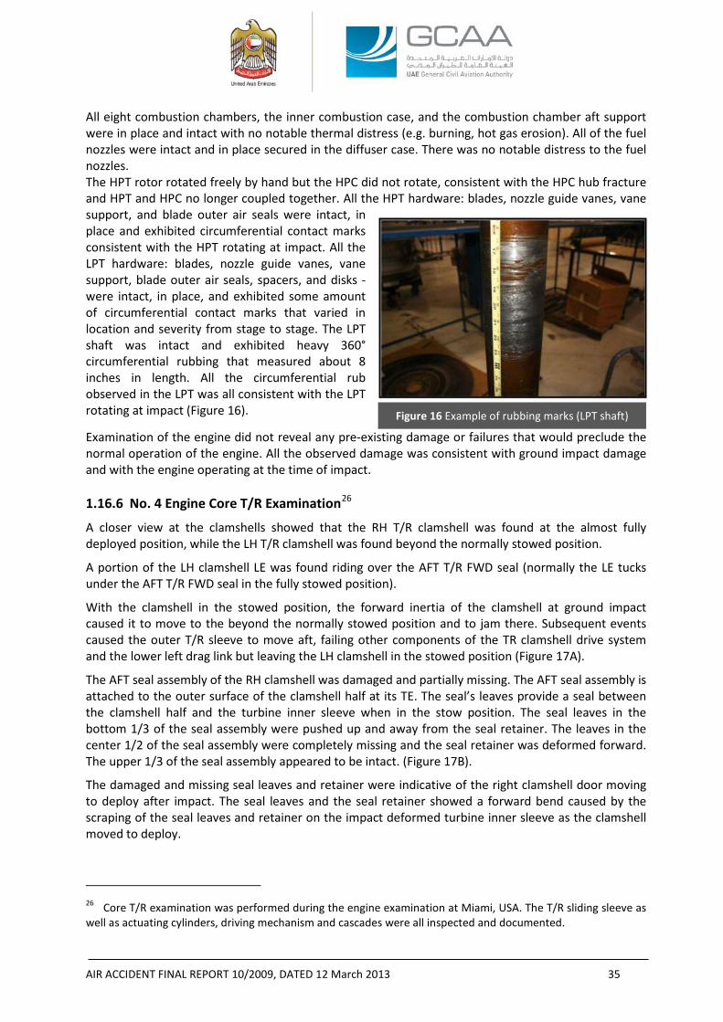
AIR ACCIDENT FINAL REPORT 10/2009, DATED 12 March 2013 35
Figure 16 Example of rubbing marks (LPT shaft)
All eight combustion chambers, the inner combustion case, and the combustion chamber aft support were in place and intact with no notable thermal distress (e.g. burning, hot gas erosion). All of the fuel nozzles were intact and in place secured in the diffuser case. There was no notable distress to the fuel nozzles. The HPT rotor rotated freely by hand but the HPC did not rotate, consistent with the HPC hub fracture and HPT and HPC no longer coupled together. All the HPT hardware: blades, nozzle guide vanes, vane support, and blade outer air seals were intact, in place and exhibited circumferential contact marks consistent with the HPT rotating at impact. All the LPT hardware: blades, nozzle guide vanes, vane support, blade outer air seals, spacers, and disks - were intact, in place, and exhibited some amount of circumferential contact marks that varied in location and severity from stage to stage. The LPT shaft was intact and exhibited heavy 360° circumferential rubbing that measured about 8 inches in length. All the circumferential rub observed in the LPT was all consistent with the LPT rotating at impact (Figure 16).
Examination of the engine did not reveal any pre-existing damage or failures that would preclude the normal operation of the engine. All the observed damage was consistent with ground impact damage and with the engine operating at the time of impact. 1.16.6 No. 4 Engine Core T/R Examination26
A closer view at the clamshells showed that the RH T/R clamshell was found at the almost fully deployed position, while the LH T/R clamshell was found beyond the normally stowed position.
A portion of the LH clamshell LE was found riding over the AFT T/R FWD seal (normally the LE tucks under the AFT T/R FWD seal in the fully stowed position).
With the clamshell in the stowed position, the forward inertia of the clamshell at ground impact caused it to move to the beyond the normally stowed position and to jam there. Subsequent events caused the outer T/R sleeve to move aft, failing other components of the TR clamshell drive system and the lower left drag link but leaving the LH clamshell in the stowed position (Figure 17A).
The AFT seal assembly of the RH clamshell was damaged and partially missing. The AFT seal assembly is attached to the outer surface of the clamshell half at its TE. The seal’s leaves provide a seal between the clamshell half and the turbine inner sleeve when in the stow position. The seal leaves in the bottom 1/3 of the seal assembly were pushed up and away from the seal retainer. The leaves in the center 1/2 of the seal assembly were completely missing and the seal retainer was deformed forward. The upper 1/3 of the seal assembly appeared to be intact. (Figure 17B).
The damaged and missing seal leaves and retainer were indicative of the right clamshell door moving to deploy after impact. The seal leaves and the seal retainer showed a forward bend caused by the scraping of the seal leaves and retainer on the impact deformed turbine inner sleeve as the clamshell moved to deploy.
26 Core T/R examination was performed during the engine examination at Miami, USA. The T/R sliding sleeve as well as actuating cylinders, driving mechanism and cascades were all inspected and documented.
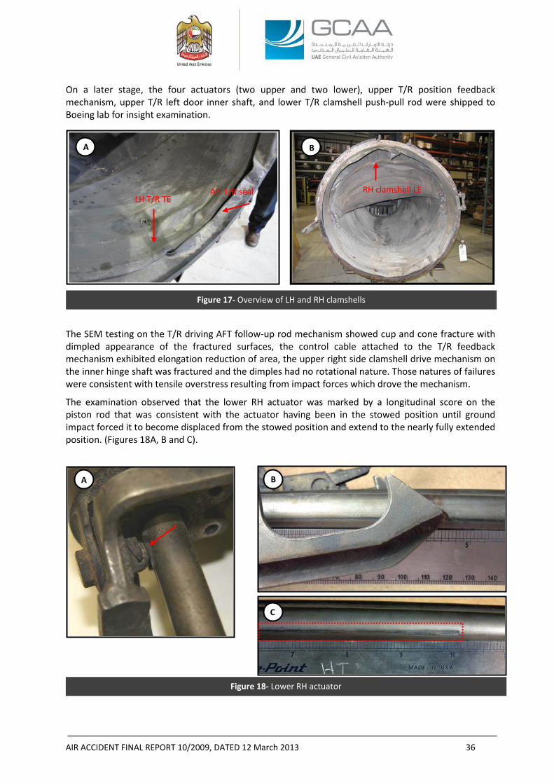
AIR ACCIDENT FINAL REPORT 10/2009, DATED 12 March 2013 36
Figure 17- Overview of LH and RH clamshells
Figure 18- Lower RH actuator
On a later stage, the four actuators (two upper and two lower), upper T/R position feedback mechanism, upper T/R left door inner shaft, and lower T/R clamshell push-pull rod were shipped to Boeing lab for insight examination.
The SEM testing on the T/R driving AFT follow-up rod mechanism showed cup and cone fracture with dimpled appearance of the fractured surfaces, the control cable attached to the T/R feedback mechanism exhibited elongation reduction of area, the upper right side clamshell drive mechanism on the inner hinge shaft was fractured and the dimples had no rotational nature. Those natures of failures were consistent with tensile overstress resulting from impact forces which drove the mechanism.
The examination observed that the lower RH actuator was marked by a longitudinal score on the piston rod that was consistent with the actuator having been in the stowed position until ground impact forced it to become displaced from the stowed position and extend to the nearly fully extended position. (Figures 18A, B and C).
A B
Aft T/R seal RH clamshell LE
B
C
A
LH T/R TE
AIR ACCIDENT FINAL REPORT 10/2009, DATED 12 March 2013 37
Since the field observations confirmed that this stowed lower actuator, along with the other three actuators (other lower actuator and two upper actuators), were properly installed and still attached at their thrust reverser outer sleeve attach points and their movement should have been simultaneous; the Investigation believes that all the four actuators were at their stowed position prior to the Aircraft impact thus the T/R was at the stowed position at impact.
The position of the LH clamshell LE over the aft T/R seal would support the above since it wouldn’t be possible to have that situation unless the LH clamshell was originally at its stowed position and the impact was strong enough to cause its high acceleration towards the seal especially after the driving mechanism had broken and no more force could have braked its movements by its own inertia.
1.16.7 Simulation with All Engines Operating and Thrust Reverser on the “Stow” Position27
After the physical examination of No. 4 engine, which revealed that the engine was rotating at the impact, and after the physical examination of the core T/R and its driving hardware which revealed that the T/R was at the “stow” position prior the impact28; a new simulation was necessitated to reflect the influence of the new information on a simulated flight.29
The objective of the simulation was to infer the flight with all engines operating under certain assumptions.
The data sources were limited to the following:
1. Six radar hits obtained from the tower surveillance radar.
2. Ground speed.
3. Altitude.
4. GPS coordinates of the first impact.
5. Weight and C.G. from the loadsheet.
27 Reference: Boeing Report No. 66-ZB-H200-ASI-18574, dated 17 December 2010. 28 Reference: Pratt & Whitney report ‘Sequence of events for Sudan Airways B707 ST-AKW No. 4 powerplant core Thrust Reverser post-impact deployment’ dated 20 April 2011 for a detailed description of the sequence of events leading to the post-impact deployment of the subject thrust reverser based on the hardware examinations. (Appendix D to this Report). 29 A previous Engineering simulation 707-300C (Reference: Boeing report No.66-ZB-H200-ASI-18511, dated 31
March 2010) was performed at Boeing facilities, the objective of which was to recreate the flight in two different cases:
(a) Typical No. 4 engine failure with a loss of thrust based on the captain’s “engine loss” report to the tower.
(b) Rapid transition to reverse thrust (both fan and core reversers) while at high power based on the initial site observation where the core cowl found at the “deploy” position.
That simulation showed a better climb gradient than the radar data. The results for the “typical” engine failure showed the pilot has the capability to utilize sufficient rudder to balance the outboard engine without sustained use of the wheel. Heading angle may be kept on the initial path and bank angle is maintained close to zero.
The simulation of “reverse thrust at high power” predicted that the simulating aircraft could be controlled in the worst case condition but only with timely input of large wheel and rudder.
The simulation discussed in this Section of the Report “With All Engines Operating and Thrust Reverser on the ‘Stow’ Position” considered the same assumptions of the previous simulation except the airspeed which was less in the latter: “V2-5” in comparison to “V2” speed in the previous simulation.
AIR ACCIDENT FINAL REPORT 10/2009, DATED 12 March 2013 38
Assumptions to the simulation were made based on the wreckage information and normal operational takeoff and single engine out emergency procedures:
1. Airspeed was assumed to be V2-5.30
2. Flaps setting was at 14 as revealed by the wreckage.
3. Landing gears were retracted as revealed by the wreckage.
4. The Aircraft was trimmed for all engine climb.
5. Eyewitnesses and security surveillance video revealed that the Aircraft descended in a high bank angle before the impact.
6. Winds were utilized to reflect the tower winds at the time of the event.
7. The sideslip angle did not exceed 10°.
To simulate the Aircraft attitude at the last radar return, a large right wheel input was made in order for the simulating aircraft to have a similar impact point. That hypothetical input application, due to the lack of FDR data, was provided as an illustration of the type of aircraft motion required to approximate the radar data and impact point.
Assumptions were also made based on the standard behavior of the pilot as a reaction to engine failure and the normal performance of the aircraft in such conditions. For that purpose, the simulation assumed that:
- The engine-out scenarios were subsequent to any engine failure already trimmed with rudder.
- Variations on thrust control were not defined whether as being a captain’s thrust retardation on No. 4 engine in response to the report to ATC that No. 4 engine was lost, or the captain’s retardation on any other engines to prepare for a return to land.
- The ground speed data from the radar did not indicate that the Aircraft was slowed precipitously during the event, but increased load factor was another way to encounter an aerodynamic stall.
- The airspeed was sufficient to have directional stability and wheel inputs were sufficient to balance the engine-out.
With an all-engine takeoff from Sharjah, and 15°-20° of bank, the simulation showed a significantly greater rate of climb capability versus the radar data. For the engine-out case, with a bank angle of 15°-20°, which was utilized to match the initial ground track, the simulation also showed a greater climb rate than the radar data. Rudder was utilized to trim the engine out and wheel was used for
30 The Airspeed used to simulate the flight was V2-5. Referring to the nearest METAR at 1138 UTC, wind speed and direction were 320°/11 kts, the maximum ground speed recorded in the radar six returns was 149 kts. The equation below was used to calculate the IAS from the TAS, ground speed and wind speed and direction:
TAS= ground speed (GS) + wind speed along the ground track (WIND). Therefore, TAS=149+11 cos 20°= 149+ (11 x 0.94)= 149+10.43= 159.43 kts (20° is the angle between the wind direction and RWY 30).
Assuming that TAS is almost equal to the CAS, and from the AFM the position error correction (“ΔVpec”) is about (- 0.50) kts, therefore IAS = CAS – ΔVpec = 159.43 – (-0.50)= 159.93 rounded to 160 kts. Comparing the calculated IAS to the AFM extracted 157 kts V2, the result would be that the IAS was higher than the V2 and therefore higher than the V2-5 airspeed used in the flight simulation.
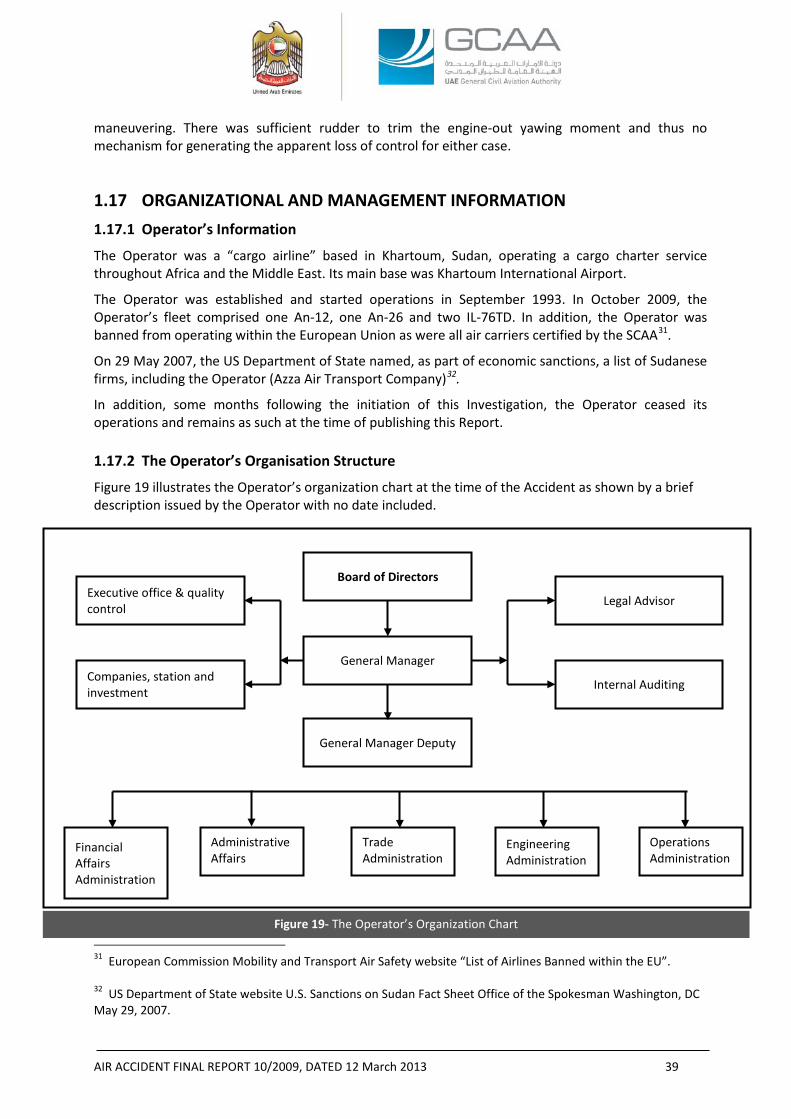
AIR ACCIDENT FINAL REPORT 10/2009, DATED 12 March 2013 39
maneuvering. There was sufficient rudder to trim the engine-out yawing moment and thus no mechanism for generating the apparent loss of control for either case.
1.17 ORGANIZATIONAL AND MANAGEMENT INFORMATION 1.17.1 Operator’s Information
The Operator was a “cargo airline” based in Khartoum, Sudan, operating a cargo charter service throughout Africa and the Middle East. Its main base was Khartoum International Airport.
The Operator was established and started operations in September 1993. In October 2009, the Operator’s fleet comprised one An-12, one An-26 and two IL-76TD. In addition, the Operator was banned from operating within the European Union as were all air carriers certified by the SCAA31.
On 29 May 2007, the US Department of State named, as part of economic sanctions, a list of Sudanese firms, including the Operator (Azza Air Transport Company)32.
In addition, some months following the initiation of this Investigation, the Operator ceased its operations and remains as such at the time of publishing this Report. 1.17.2 The Operator’s Organisation Structure
Figure 19 illustrates the Operator’s organization chart at the time of the Accident as shown by a brief description issued by the Operator with no date included.
31 European Commission Mobility and Transport Air Safety website “List of Airlines Banned within the EU”. 32 US Department of State website U.S. Sanctions on Sudan Fact Sheet Office of the Spokesman Washington, DC May 29, 2007.
Figure 19- The Operator’s Organization Chart
Board of Directors
General Manager
Legal Advisor
Internal Auditing
General Manager Deputy
Administrative Affairs
Trade Administration
Engineering Administration
Operations Administration
Executive office & quality control
Companies, station and investment
Financial Affairs Administration
AIR ACCIDENT FINAL REPORT 10/2009, DATED 12 March 2013 40
1.17.3 Operator’s Maintenance Procedure
At the time of the Accident, the onboard maintenance engineer was the only engineer within the Operator’s maintenance organization who was holding the authorization to release the Aircraft to service.
The maintenance engineer was certificated by the SCAA under the ANR which bestows the privilege to the engineer to conduct, sign, and release to service any aircraft after company authorization is granted to him.
Although the corrective actions for each pilot entry was reserved a space next to the entry, the technical logbook of the Aircraft did not include dedicated space for Airworthiness Release. 1.17.4 Operator’s Operations Procedure
During the time of the Investigation, the Team requested the following information: • Crew Resource Management training file • Ground training file • Human factors training • Recurrent training • Simulator training • Emergency training • Flight crew training manual • Flight crew records (before and after joining the Operator) • Any other information/records that might introduce benefits to the investigation
especially those related to the 72 hours history.
In response to the Investigation’s request, the personal files of the flight crew members were provided as described in paragraph 1.5 of this Report, along with the following Sudan ANRs:
• PARTS I and II dated February 2004 issue 1 (Definitions- Abbreviations, Registration of Civil Aircraft in the Republic of Sudan);
• PART III (Certification of aircraft and products);
• PART IV (General Technical and Administrative Requirements);
• PART V (Maintenance Organizations of Commercial Aircraft);
• PART VI (Approval of Small Aircraft Maintenance Organizations);
• PART VII (Air Operating Certificate (AOC));
• PART VIII dated February 2004 issue 1 (Volume 1 General Operating & Flight Rules, Volume 2 Air transport Operations Large Aeroplanes, Volume 3 Air Transport Operations of Small Aeroplanes, Volume 4 Air Transport Operations Foreign, Volume 5 Operation of Ultra Light Aircraft, Volume 6 Balloons and Volume 7 Operations of Gliders);
• PART IX dated February 2004 issue 1 (Volume 1 Pilot Licensing, Volume 2 Flight Engineer Licensing, Volume 3 Cabin Crew Licensing, Volume 4 Maintenance Personnel Licensing, Volume 5 Medical Certification);
AIR ACCIDENT FINAL REPORT 10/2009, DATED 12 March 2013 41
• PART XI dated November 2006 issue 2 (Conveyance of Dangerous Goods); and
• PART XII dated February 2004 issue 1 (Volume 1 Airport Security, Volume 2 Commercial Air Operator Security and Volume 3 Foreign Operator Security).
1.17.5 Fatigue Risk Management System
At the time of the Accident, the Operator was not following nor it was required to have a process of Fatigue Risk Management System (“FRMS”). There was no such system in place, nor it was required to do by the ANRs. Fatigue management was based on descriptive rules. 1.17.6 Operator’s Crew Training Policy
During the Investigation, the Team could not obtain the flight crew training program and records thus the Investigation was not able to review the Operator’s training policy and procedures for engine-out, nor the historical performance of the same crew in handling such conditions. 1.17.7 Lease Agreement
At the time of the Accident, the Aircraft was being operated under a lease agreement, signed on 27 April 2009, between the Operator “lessor” and Sudan Airways “lessee”. The agreement was referring to ACMI terms: the lessor was responsible for the aircraft, crew, maintenance and insurance whereas the lessee was responsible for operational expenses including the fuel, catering, and fees associated with landing, overflying, and ground handling.
No evidence was provided to the Investigation of any type of operations oversight performed by the lessee neither during the selection process of the lessor nor during the actual operation of the flights.
1.17.8 SCAA’s Audits on the Operator
The Investigation was provided with the following:
(a) An SCAA letter dated 20 August 2009 (in Arabic) with the subject “Audit Date Change” addressed to the General Manager of the Operator informing that due to various reasons it was decided to postpone the audit to Thursday 3 September 2009.
(b) The Investigation was additionally presented with a single page A4 size paper, dated 12 October 2009 (written in English) reflecting the following findings after “AOC renewal audit” conducted by the SCAA33:
“
1. Operation Manual not approved.
2. Organization chart needs review.
3. No quality organization was seen.
4. Quality did not perform audit on operation department.
5. No quality audit program was seen.
6. No annual training program.
7. No crew training program is made.
8. Crew records, especially training, not seen.”
33 Quoted from the SCAA letter
AIR ACCIDENT FINAL REPORT 10/2009, DATED 12 March 2013 42
Line Maintenance Department:
“
1. None of the company manuals identified by company documentation numbers.
2. No manual or references to other manuals outlining the line maintenance procedures for control of records material supply and provision of assistance of the operation of the aircraft outside stations.
3. Line maintenance management staff and certifying staff-poor management and minimum staff.
4. Trips or monthly reporting system not implemented.”
(c) A letter (in Arabic) dated 20 October 2009 indicating that a finance audit was performed.
(d) A letter (in Arabic) dated 12 October 2009 in a form of minutes of meeting following an audit. Attendees were from the SCAA and the Operator.
During that meeting, the Operator gave a brief about its development history as of that it started operation in 1993 when it was owned by the Ministry of Defense, the Operator initially started with one IL-76 and thereafter reached to six IL 76 all owned by the Operator. Thereafter the Operator added B707, An-26 and An-12 for domestic and international operations.
Furthermore, the Operator informed the SCAA that the Operator:
• was developing its own facilities to operate cargo flights in different Sudanese airports such as Juba and Genena Airport;
• was having problems with spare parts;
• training was a priority but there were no simulators available;
• was operating all its aircraft;
• was having a specialist for Dangerous Goods and approvals from the SCAA for DG transportation;
• most of the crew members were Sudanese;
• was having approved key processes;
• was not operating any leased aircraft; and
• Operations Manuals were approved by the SCAA.
(e) A letter (in Arabic) from the SCAA-Airworthiness to the SCAA-Aviation Safety dated 22 October 2009 under the title “Azza AOC Suspension Letter” indicating that: due to the repetitive accidents during the last few days including the accident of Sharjah, we see to suspend the AOC of AZZA until a committee, for Studying the operation performance evaluation, is formed.
(f) A letter dated 1 November 2009 (in Arabic) under the title “audit findings” from the SCAA to the General Manager of the Operator referring to the audit dated 12 October 2009, informing that there were findings in Operation, Airworthiness and Financial Capability and asking the Operator to address the findings as soon as possible.
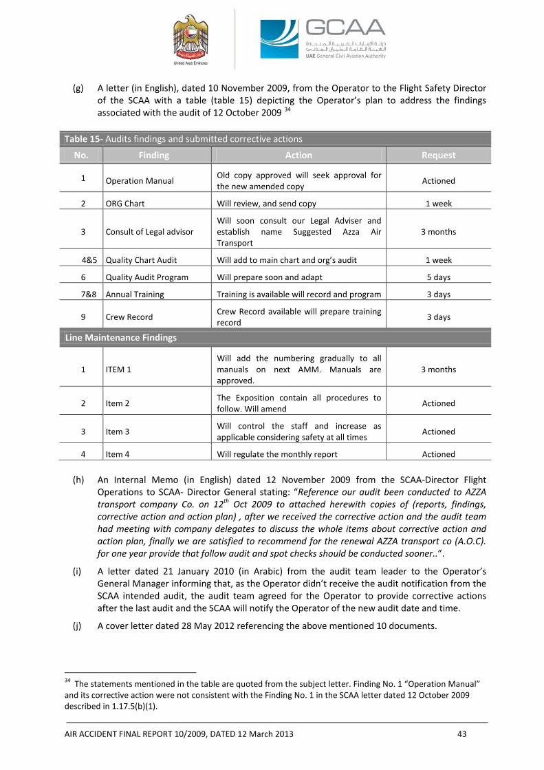
AIR ACCIDENT FINAL REPORT 10/2009, DATED 12 March 2013 43
(g) A letter (in English), dated 10 November 2009, from the Operator to the Flight Safety Director of the SCAA with a table (table 15) depicting the Operator’s plan to address the findings associated with the audit of 12 October 2009 34
Table 15- Audits findings and submitted corrective actions
No. Finding Action Request
1 Operation Manual Old copy approved will seek approval for the new amended copy Actioned
2 ORG Chart Will review, and send copy 1 week
3 Consult of Legal advisor Will soon consult our Legal Adviser and establish name Suggested Azza Air Transport
3 months
4&5 Quality Chart Audit Will add to main chart and org’s audit 1 week
6 Quality Audit Program Will prepare soon and adapt 5 days
7&8 Annual Training Training is available will record and program 3 days
9 Crew Record Crew Record available will prepare training record 3 days
Line Maintenance Findings
1 ITEM 1 Will add the numbering gradually to all manuals on next AMM. Manuals are approved.
3 months
2 Item 2 The Exposition contain all procedures to follow. Will amend Actioned
3 Item 3 Will control the staff and increase as applicable considering safety at all times Actioned
4 Item 4 Will regulate the monthly report Actioned
(h) An Internal Memo (in English) dated 12 November 2009 from the SCAA-Director Flight Operations to SCAA- Director General stating: “Reference our audit been conducted to AZZA transport company Co. on 12th Oct 2009 to attached herewith copies of (reports, findings, corrective action and action plan) , after we received the corrective action and the audit team had meeting with company delegates to discuss the whole items about corrective action and action plan, finally we are satisfied to recommend for the renewal AZZA transport co (A.O.C). for one year provide that follow audit and spot checks should be conducted sooner..”.
(i) A letter dated 21 January 2010 (in Arabic) from the audit team leader to the Operator’s General Manager informing that, as the Operator didn’t receive the audit notification from the SCAA intended audit, the audit team agreed for the Operator to provide corrective actions after the last audit and the SCAA will notify the Operator of the new audit date and time.
(j) A cover letter dated 28 May 2012 referencing the above mentioned 10 documents.
34 The statements mentioned in the table are quoted from the subject letter. Finding No. 1 “Operation Manual” and its corrective action were not consistent with the Finding No. 1 in the SCAA letter dated 12 October 2009 described in 1.17.5(b)(1).
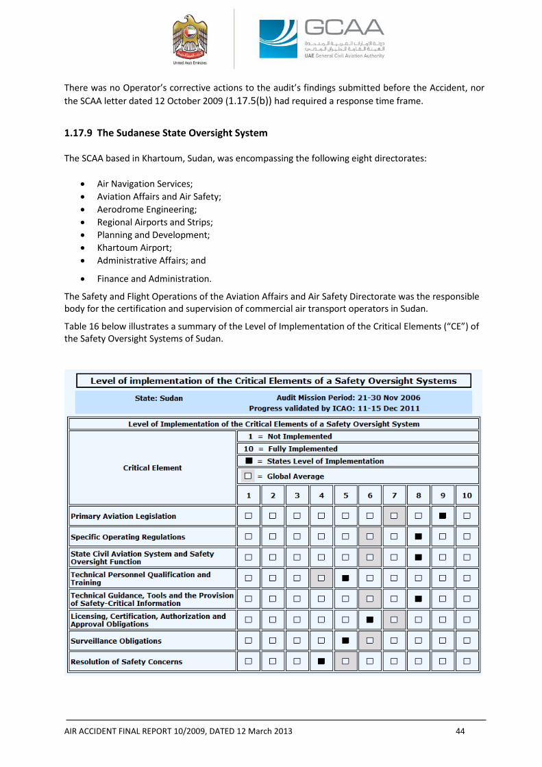
AIR ACCIDENT FINAL REPORT 10/2009, DATED 12 March 2013 44
There was no Operator’s corrective actions to the audit’s findings submitted before the Accident, nor the SCAA letter dated 12 October 2009 (1.17.5(b)) had required a response time frame.
1.17.9 The Sudanese State Oversight System
The SCAA based in Khartoum, Sudan, was encompassing the following eight directorates:
• Air Navigation Services; • Aviation Affairs and Air Safety; • Aerodrome Engineering; • Regional Airports and Strips; • Planning and Development; • Khartoum Airport; • Administrative Affairs; and
• Finance and Administration.
The Safety and Flight Operations of the Aviation Affairs and Air Safety Directorate was the responsible body for the certification and supervision of commercial air transport operators in Sudan.
Table 16 below illustrates a summary of the Level of Implementation of the Critical Elements (“CE”) of the Safety Oversight Systems of Sudan. Table 16- Level of implementation of the Critical Elements of a Safety Oversight Systems
AIR ACCIDENT FINAL REPORT 10/2009, DATED 12 March 2013 45
Recently, the Republic of Sudan agreed to an ICAO Coordinated Validation Mission (“ICVM”), which was conducted from 11 to 15 December 2011. The mission evaluated the status of implementation of the latest corrective action plan (“CAP”) of the State on the Universal Safety Oversight Audit Program (“USOAP”) Findings & Recommendations (“F&Rs”). A second ICVM was conducted from 16 to 19 May 2012 to validate the corrective actions taken by Sudan in response to the Significant Safety Concern (“SSC”) found in the first ICVM.
The USOAP audit of the civil aviation system of Sudan conducted in 2006 generated 87 findings, with 399 Protocol Questions (“PQs”) found not satisfactory. The Lack of Effective Implementation (“LEI”) of the eight CEs before the first ICVM was 50.7%.
During the first ICVM, the ICVM team reviewed the progress made by the State in addressing 87 F&Rs, covering 399 PQs in the areas of LEG, ORG, PEL, OPS, AIR, AIG, ANS and AGA35. Following the review, the status of 158 PQs was changed to satisfactory and 2 PQs was changed to not applicable, which resulted in updated LEI of 31.1%.
The same ICVM also generated a Significant Safety Concern (“SSC”) when it was found that Sudan had issued AOCs to 18 air operators, including some international air operators, while the certification process leading to the issuance of an AOC did not provide full evidence of compliance with the applicable standards of Annex 6 to the Convention on International Civil Aviation as well as with the national certification requirements.
After the second ICVM, which was conducted for the purpose of validating the corrective actions taken by the SCAA in response to the SSC, the status of 26 PQs was changed to “satisfactory”, resulting in updated LEI of 26.4%. Based on the finding of this ICVM and evidence provided by the State, the ICAO SSC Validation Committee on 31 May 2012 concluded that the SSC on the air operator certification process of Sudan had been successfully resolved.
1.17.10 The UAE Foreign Operators’ Oversight System
The GCAA of the UAE was founded in 1996 by Federal Cabinet Decree (Law 4) to regulate civil aviation in the UAE and provide designated aviation services with observance to the safety and security to strengthen the aviation industry within the UAE and its upper space.
The GCAA’s regulatory system has a provision for the Foreign Air Transport Operations in the UAE. CAR Part III, Chapter 6 prescribes regulations applicable to foreign air transport operations within the country. This chapter has provisions for foreign operators to carry their aircraft certificates and documents onboard. In addition, there is a provision for the crew members to possess and carry their licenses with them and each pilot to be familiar “with the applicable rules, the navigational and communications facilities, and the air traffic control and other procedures, of the areas to be traversed by him within the UAE.”
Chapter 6 doesn’t have any provision for approving or performing a review of the foreign operator qualification/performance before granting approval to commence its operation into the UAE.
In addition, the GCAA has published a Notice of Proposed Amendment (NPA 02-2011) under the title “CAR-OPS 4- Commercial and Non-Commercial Air Transport Operations by Foreign Air Operators in United Arab Emirates”. The proposed CAR-OPS 4 “prescribes the requirements for the approval, surveillance and resolution of safety issues associated with commercial and non commercial air transport operations by foreign air operators in the UAE.”
35 LEG, ORG, PEL, OPS, AIR, AIG, ANS and AG are areas of USOAP which mean Legislation, Organization, Personnel Licensing, Flight Operations, Airworthiness, Investigation, Air Navigation and Aerodromes.
AIR ACCIDENT FINAL REPORT 10/2009, DATED 12 March 2013 46
In more details, according to the proposed CAR-OPS 4:
(a) No person shall conduct any commercial air operation to a UAE civil aerodrome unless is in possession of and in compliance with a valid Foreign Air Operator Certificate issued by the GCAA.
(b) It is the responsibility of the Foreign Air Operator to ensure that all flight operations conducted in the UAE are in continuous compliance with the UAE Civil Aviation Law, any other applicable law, CAR-OPS 4, any other applicable CAR and all operational directives and instructions promulgated by the GCAA.
The proposed CAR-OPS 4 has provisions for applicants from ICAO Contracting States on how to submit an application for the issuance of a Foreign Air Operator Certificate completed in accordance with the prescribed application requirements published by the GCAA and the requirement for the evaluation of the application for a foreign operator that would like to commence operations into the UAE.
After the Accident, the GCAA formed a department dedicated to oversight foreign Operators.
1.18 ADDITIONAL INFORMATION
1.18.1 Engine Failure and Shutdown Emergency/Abnormal Checklist
According to Boeing Aircraft Operations Manual, in the Emergency/Abnormal Checklist for handling engine failure and shutdown, the emergency procedure starts with the captain who shall close the thrust lever unless, if the conditions permit, he should operate the engine at idle for 2 minutes. Then the captain shall cutoff the start lever. The co-pilot shall switch off the nacelle anti-ice and engine start control selector, the flight engineer shall trip the generator breaker switch, monitor the electrical loads and switch the fuel shutoff valve to CLOSE position followed by switching the air compressor/bleed air to STOP/OFF position.
The Checklist adds that the flight crew should complete normal descent-approach and landing checklists and it recommends accomplishing, if appropriate, TWO ENGINES INOPERATIVE or ONE ENGINE AND RUDDER BOOST INOPERATIVE LANDING checklist.
Figure 20 illustrates a chart of takeoff path for “Engine Fire/Failure After V1” 36. In this procedure, the
Operations Manual limits the bank angle to 15° until reaching V2+10 kts in case of 14 flaps configuration or V2+50 kts in case of clean configuration (no flaps and landing gear retracted), after either of these speeds is attained, a 30° bank can be initiated. For the Accident Aircraft, the bank was increased rapidly before reaching the 14 flaps V2+10 kts speed condition.
“Takeoff Procedure with Failed Engine” in the AFM describes that when an engine failure occurs, the take-off should be aborted when the failure is recognized prior to V1 and should be continued when it is recognized after passing V1.
When the takeoff is continued, the AFM says that the pilot flying (“PF”) shall control the rate of rotation to target the V2 at 35 ft height, retract landing gear after a positive rate of climb has been established then follow the “Normal All-Engines-Operating Takeoff Climb-out” procedures and speeds if the situation is “Non-Obstacle Limited Climb-out”.
Furthermore during the course of the Investigation, it was revealed that the Operator didn’t have engine out procedures specific for Sharjah Airport.
36 Reference Boeing Operations Manual, Section 03-30-02.
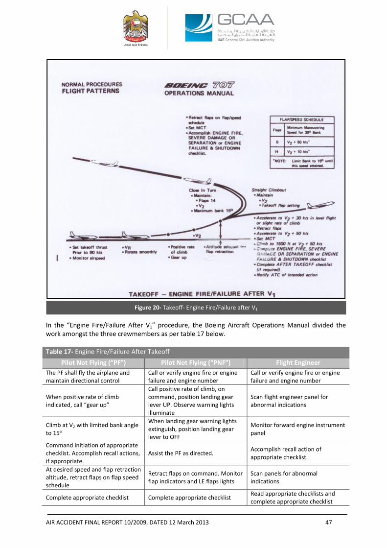
AIR ACCIDENT FINAL REPORT 10/2009, DATED 12 March 2013 47
In the “Engine Fire/Failure After V1” procedure, the Boeing Aircraft Operations Manual divided the work amongst the three crewmembers as per table 17 below. Table 17- Engine Fire/Failure After Takeoff
Pilot Not Flying (“PF”) Pilot Not Flying (“PNF”) Flight Engineer The PF shall fly the airplane and maintain directional control
Call or verify engine fire or engine failure and engine number
Call or verify engine fire or engine failure and engine number
When positive rate of climb indicated, call “gear up”
Call positive rate of climb, on command, position landing gear lever UP. Observe warning lights illuminate
Scan flight engineer panel for abnormal indications
Climb at V2 with limited bank angle to 15°
When landing gear warning lights extinguish, position landing gear lever to OFF
Monitor forward engine instrument panel
Command initiation of appropriate checklist. Accomplish recall actions, if appropriate.
Assist the PF as directed. Accomplish recall action of appropriate checklist.
At desired speed and flap retraction altitude, retract flaps on flap speed schedule
Retract flaps on command. Monitor flap indicators and LE flaps lights
Scan panels for abnormal indications
Complete appropriate checklist Complete appropriate checklist Read appropriate checklists and complete appropriate checklist
Figure 20- Takeoff- Engine Fire/Failure after V1
AIR ACCIDENT FINAL REPORT 10/2009, DATED 12 March 2013 48
items.
Determine next course of action On command, notify ATC and advise of next course of action.
On command, set maximum thrust as required
1.18.2 Calculating the Takeoff Parameters
According to the AFM, at 32 °C OAT, sea level, 131,505 kg (289,919 pounds) gross weight, with engine anti-ice at OFF position; takeoff parameters are as follows37:
Normal takeoff EPR: 1.80 38
N1 for maximum takeoff thrust: 109%
V1: 136 kts
VR : 142 kts
V2 : 157.5 kts
Vs: 130 kts IAS (level flight)
VMCA: 125 kts with maximum takeoff thrust
VMCG: 126 kts IAS with maximum takeoff thrust
The examination of No. 4 engine EPR gauge revealed that the engine target EPR was, most probably, set at 1.78 as depicted by the gauge counter window, which was approximately 0.02 less than the normal takeoff EPR (1.78 in comparison with 1.80). 1.18.3 Inadvertent In-flight Reverse Thrust
Although the Investigation did not find any indication of in-flight reverse thrust, the protection of deliberate in-flight reverse thrust was only provided by the following warning statement in Section II of the AFM under the title “Emergency Operating Procedure”:
“DELIBERATE INTERLOCK ACTUATION OF REVERSE THRUST IS PROHIBITED”.
37 According to the AFM: V1- is the speed at which, if an engine failure occurs, the distance to continue the takeoff to a height of 35 ft will not exceed the usable takeoff distance or the distance to bring the airplane to a full stop, will not exceed the accelerate-stop distance available. V1 must not be less than the ground minimum control speed (“VMCG”) or greater than the rotations speed (“VR”‘) or greater than the maximum brake energy limit speed (“VMBE”). VR- is the speed at which if rotation is initiated during the takeoff to attain V2 climb speed at the 35 ft height. VR must not be less than 1.05 times the air minimum control speed (“VMCA”). V2- is the actual speed at the 35 ft height as demonstrated in-flight. This speed must not be less than 1.2 times the minimum stall speed in the takeoff configuration nor less than 1.1 times the VMCA. VMCA- is the minimum flight speed at which the airplane is controllable with a maximum of 5° bank when one outboard engine suddenly becomes inoperative and the remaining engines are operating at takeoff thrust. VMCG- is the minimum speed on the ground at which the takeoff can be continued, utilizing aerodynamic controls alone, when an outboard engine suddenly becomes inoperative and the remaining engines are operating at takeoff thrust. 38 Reference FAA approved AFM, Section IV, with the following conditions: Cabin pressurization Air Bleed- OFF, turbocompressor- OFF, static takeoff, wing and nacelle anti-ice- OFF, dry runway.
AIR ACCIDENT FINAL REPORT 10/2009, DATED 12 March 2013 49
1.18.4 Interviews
• When he was asked about the manuals that should be available onboard the Aircraft, the Operation’s Director of Sudan Airways answered that all the manuals belonged to Azza Air Transport as being the lessor of the Aircraft and they (Azza Air Transport) had the operations control as per the lease agreement.
• In his interview, the maintenance technician, who was involved in the pre-flight check of the departing flight from Khartoum to Sharjah, stated that he arrived at the Aircraft in the early morning and he did not observe any abnormalities amongst the flight and maintenance crew. The Aircraft departed from Khartoum Airport with a delay due to the priority given by the Khartoum Airport ATC to a passenger aircraft. He added that to his knowledge there were no repetitive snags or deferrals on the Aircraft.
• In his interview, a maintenance engineer, who was involved in the maintenance of another Operator’s aircraft located at the Sharjah Airport, revealed that he met and had a conversation with the flight and maintenance crews before the flight and did not observe anything abnormal. He added that he did not observe if the Aircraft maintenance engineer had made any repair or maintenance action other than a walk around.
• In his interview, the Operator’s Director of Quality revealed that the Operator had a line maintenance section within the maintenance structure but base maintenance was usually performed by the Egyptian Civil Aircraft Maintenance (‘ECAM’).
He added that he did not attend the last C-Check that was performed in Egypt but attended the B-Check performed by the ECAM staff in Khartoum. The maintenance was performed according to a pre-signed contract between the Operator and ECAM after satisfaction of the Operator’s quality management.
• The Director of Quality added that, to his knowledge, the Aircraft had no gripes, deferrals, or open AD. He was aware of a repetitive AD pertinent to the communication, that was due every 18 months. There was no abnormal engine oil consumption nor thrust reverser anomalies.
• In his interview, the Operator’s Director of Engineering revealed that the Aircraft was normal and they used to perform the line and base maintenance without any maintenance write-ups.
• In his interview, the Operator’s Director of Maintenance Center revealed that the Aircraft was being maintained by qualified personnel who did not write-up any maintenance issues or airworthiness defects. He added that the involved maintenance engineer had some conversation with him one day before the Accident and he did not mention anything abnormal.
• In his interview, the Operator’s Director of Operations revealed that the captain was competent, decisive, had a normal family and economy life, and the flight crew composition was homogeneous.
He added that he did not know who was the PF in the Accident flight but, to his knowledge, the captain was usually in command during the takeoff and landing phases.
• In his interview, ECAM’s maintenance engineer, who worked on the Aircraft in the last C- Check, revealed that general inspections were performed on the engines’ cowls after cleaning. One of the engines’ cowls was found “twisted” that required them to do a ”slight adjustment” after which the cowl worked normally.
• In his interview, ECAM’s avionics/instruments technician revealed that during the C-Check he found, in some occasions, various revisions for the same pages in the AMM and he used the most up to date revisions.
AIR ACCIDENT FINAL REPORT 10/2009, DATED 12 March 2013 50
When questioned whether he conducted tests on the FDR, he answered that tests did not reveal any defects. He said that there was one way to differentiate between the foil type and the more modern types of the FDRs from the external view by checking if there is an access to replace the foil’s magazine since the newer types would not have such an access. According to that fact, he identified the Aircraft FDR as a type of non-replaceable and thus as the newer type.
There were no abnormalities with the remaining hours indicator fixed at the FDR.
He added that he did not have maintenance cards for checking the CVR.
• In his interview, the ECAM’s communications technician stated that he worked on the routine inspection cards and noticed that most of the work was visual inspection which was less than the cards he used to work for similar checks.
He added that the only check of the CVR was by pressing the cockpit switch; when it illuminates “green” it would mean that the CVR was functioning. When he performed the test the green light illuminated so he concluded that the CVR was working.
• In his interview, the Operator’s Regional Manager at Sharjah Airport revealed that he accompanied the crew into the duty free shops at the Airport for approximately half an hour. The captain, co-pilot, and flight engineer were all happy while they were shopping for their families. They left the duty free to the departure gate where the Manager left them to go back to his office.
• In his interview, the Ramp Agent loading supervisor stated that prior to the departure he “saw one engineer adding oil to, what he guessed, was the No. 3 engine”. He added that he finished his loading work and completed the paperwork normally without any noticeable issues.
• The operator of the pushback tug stated that he “pushed the Aircraft and did not see anything unusual, everything was normal”.
• In his interview, an eyewitness, who was a pilot situated near the crash site, stated that the Aircraft looked very heavy at takeoff and low with initially level wings and gear-up. The wings were level from liftoff to approximately 400 ft. The eyewitness added that the Aircraft was struggling to gain altitude and “the nose was not or did not appear to be in a positive climb attitude, the nose was not above the horizon looking at it as a pilot point of view, it was clear that the Aircraft was not a normal case”. Then the Aircraft started to turn to the right 10° to 15° with normal engines sound. The Aircraft continued on turn and the nose pitched up very quickly and the bank angle also started to increase, from 10°-15° to about 60°-70°.
As he perceived, the engines’ throttles were advanced to maximum power as concluded by the change in their sound, then the bank angle increased to the right to become close to 80°-90° immediately before the Aircraft went into a sideway dive with probably the nose impacting the ground first.
• In his interview, the Airport’s Safety Manager stated that the takeoff and initial climb were normal, suddenly he heard a change in the Aircraft performance sound, the noise decreased suddenly but there was still normal exhaust smoke from the engines. The Aircraft height was from 500 to 600 ft when he saw the falling part.
He added that the takeoff was approximately from the middle of the runway and the part fell close to the end of the runway. After that, the Aircraft engines’ noise became less without any sign of fire, and then the Aircraft went into a sharp turn to the right and started a very deep sink to the ground.
AIR ACCIDENT FINAL REPORT 10/2009, DATED 12 March 2013 51
1.18.5 Annex 6 on the International Civil Aviation, Part I- Flight crew member training programs
According to Annex 6, Part I, paragraph 9.3, current at the time of the Accident:
“An operator shall establish and maintain a ground and flight training programme, approved by the State of the Operator, which ensures that all flight crew members are adequately trained to perform their assigned duties. The training programme shall:
a. include ground and flight training facilities and properly qualified instructors as determined by the State of the Operator;
b. consist of ground and flight training in the type(s) of aeroplane on which the flight crew member serves;
c. include proper flight crew coordination and training in all types of emergency and abnormal situations or procedures caused by engine, airframe or systems malfunctions, fire or other abnormalities;
d. include training in knowledge and skills related to visual and instrument flight procedures for the intended area of operation, human performance including threat and error management and in the transport of dangerous goods;
e. ensure that all flight crew members know the functions for which they are responsible and the relation of these functions to the functions of other crew members, particularly in regard to abnormal or emergency procedures; and
f. be given on a recurrent basis, as determined by the State of the Operator and shall include an assessment of competence.”.
In addition, Annex 6, Part I, paragraph 9.4 states:
“An operator shall ensure that piloting technique and the ability to execute emergency procedures is checked in such a way as to demonstrate the pilot’s competence on each type or variant of a type of aeroplane. Where the operation may be conducted under instrument flight rules, an operator shall ensure that the pilot’s competence to comply with such rules is demonstrated to either a check pilot of the operator or to a representative of the State of the Operator. Such checks shall be performed twice within any period of one year. Any two such checks which are similar and which occur within a period of four consecutive months shall not alone satisfy this requirement.”
Paragraph 9.4 adds:
“When an operator schedules flight crew on several variants of the same type of aeroplane or different types of aeroplanes with similar characteristics in terms of operating procedures, systems and handling, the State shall decide under which conditions the requirements of 9.4.4.1 for each variant or each type of aeroplane can be combined”.
1.19 USEFUL OR EFFECTIVE INVESTIGATION TECHNIQUES None.
AIR ACCIDENT FINAL REPORT 10/2009, DATED 12 March 2013 52
2. ANALYSIS
2.1 NO. 4 ENGINE COWLS The No. 4 engine cowls exhibited repairs that were not to the quality of aviation standards.
The review of the provided maintenance records revealed that the cowls were, at least, inspected in two occasions prior to the Accident: the first was during the C3-Check and the second was during the B-Check, the time span between the two checks was approximately 6 months.
In the C3-Check, JIC sequential No. 15 called for visual check of No. 4 engine LH and RH cowls, accordingly NRC No. 081 was raised by the inspection personnel stating that the No. 4 engine cowl was very difficult to open and close, the corrective action to that finding was “No. 4 engine cowl found slightly twisted and need to be adjusted, repaired carried out”. The corrective action was performed by the same person who completed JIC 15 and raised NRC 081. (Refer to Appendix A to this Report).
In the B-Check, RIC sequential No. 05 prepared by the Operator called for checking “the No. 4 engine cowl panel, hook, latch fasteners, cowl panel support rod for condition, missing items and security”. The maintenance action, taken by ECAM maintenance personnel, to that RIC was that “Checked and necessary repaired C/O”, the AMM reference was indicated in the RIC as 71-5-0. (Refer to Appendix B to this Report).
Although the last B-Check included a repair action to the cowls, the aged appearance of repairs made the Investigation believe that it is, most probably, that these repairs were not new and might have been performed at earlier date to the last C3-Check. The multiple double holes and alignment pin indents in the RH cowl latch line (figure 11) and bent and distorted alignment pins and U-bolt receptacles indicate that the cowl misalignment was not new and that closing and latching of the two mating cowl halves would have required more force than normally specified in the AMM 71-5-21, page 205 since at least one of the guide pins, at location F of the RH cowl was, mistakenly, not engaging with its pin hole and instead of that it was protruding and making a new hole adjacent to the original pin hole.
The issues of improper and poor repairs were not unique to the cowls, the hinge support structure that was recovered on the departure end of RWY 30 along with the cowls showed poor quality repairs: market type welding, use of incorrect material and missing hardware (the roller). Those repairs had existed for some time without proper inspection and monitoring (paragraph 1.16.2 in this Report). Although, the fatigue striations found on the hinge support did not cause the support to fail and separate from the pylon, striations showed a systemic problem with the quality of repairs performed on the Aircraft and the maintenance program that allowed them to be performed.
Based on the physical evidence of the LH and RH cowls and their associated hardware, the cowl departure sequence was most likely as follows:
• The No. 4 engine cowls were not properly latched at takeoff, and based on data provided by Boeing, air loads and vibration acting on the improperly latched cowls, caused the E and F aft latch U-bolt fitting supports to fail and rip out from the LH cowl but remained attached to the RH latches.
• The partially opened cowls experienced an increase in the air load and high level of vibration that caused the cowls to move and twist and forced the cowls aft and up and to the right allowing the RH cowl hinges to start to disengage. That was consistent with the heavy bending and deformation seen on the LH fittings and the slight bending seen on the RH fittings.
• The RH cowl disengaged from the pylon first and pulled the LH cowl, that was still attached by latches A through D, along with it. The RH cowl No. 5 hinge fitting, one of the three RH latches
AIR ACCIDENT FINAL REPORT 10/2009, DATED 12 March 2013 53
that exhibited 40° or more of bending, ripped out the hinge support structure that was found along with the cowlings.
The reason for the failure of the cowl hinge support structure was that it could not withstand the high loads and twisting with the No. 5 hinge partially engaged in the support structure as the cowl separated from the Aircraft. The RH and LH cowlings remained attached until they hit the ground.
• When the hinge support structure separated, it impacted the Pt7 flex line just aft of it causing flex line to become disconnected from the manifold leading to the loss of the Pt7 signal and a false EPR displayed to the flight crew.
2.2 ENGINE PERFORMANCE The Investigation could not determine the No. 1 and 2 engine parameters and power setting
since there was no source of data available; no indicators were recovered.
When the No. 4 engine cowl hinge support structure ripped off the pylon, the sense line from the Pt7 manifold was severed resulting in a loss of the Pt7 signal to the EPR transmitter. With the severed Pt7 manifold, the EPR transmitter would have received the engine nacelle ambient pressure instead of the engine total exhaust pressure. The flight crew would have seen an EPR value of around 1.05, which according to the ATC transcript, the captain had most likely interpreted and reported it as an engine loss which was inconsistent with the findings that the engine damage was indicative of high speed rotation at the time of impact.
The crew never reported any problems from the beginning of the takeoff until the declaration of the No. 4 engine perceived loss; therefore it was reasonable to assume that the all four engines reached their target EPR values at least before the declaration of No. 4 engine loss.
2.3 AIRCRAFT PERFORMANCE The exact performance of the Aircraft could not be identified due to the lack of flight
recorders’ information. Therefore, the Investigation examined other sources of information provided by the witnesses, the wreckage analysis and the aerodynamic and mathematical simulations performed by Boeing.
Although the examinations could not determine the No. 4 engine output power, it was determined that the engine was rotating at relatively high speed and operating normally consistent with a high power setting. Additionally the core thrust reverser was believed to be at the “stow” position, therefore the Investigation excluded that No. 4 engine in-flight shutdown or thrust reverser in-flight deployment were behind the abnormal Aircraft attitude immediately prior to the impact.
The free movement of the control surfaces, the flaps setting and the Aircraft integrity prior to the impact excluded the probability of adverse controllability due to failure of the primary or secondary flight control surfaces.
The additional parasite drag that was resulted from the separation of the cowls was not excessive to cause a significant differential force that could result in inadvertent aircraft yaw or other controllability difficulties.
From the time the Aircraft disappeared from the view of the Airport security surveillance video until its reappearance (about 22 s), neither the rate of climb nor the attitude could have been determined, but according to the eyewitness pilot, the Aircraft was climbing with level wings attitude and shallow rate of climb until leveled off before entering into the turn.
AIR ACCIDENT FINAL REPORT 10/2009, DATED 12 March 2013 54
Aircraft performance literature explains that, in steady-state climbs, the aircraft rate of climb is directly proportional to the difference between the available thrust and drag and inversely proportional to the weight. The more excess thrust (thrust minus drag) available the higher the pitch angle and consequently the rate of climb.39
Alternatively, a coordinated turn requires increasing lift to balance weight and to provide horizontal centripetal force to sustain the banked turn.
Assuming that No. 4 engine was not generating any thrust, which was not the case, and, accordingly, the captain had decided to return to the Airport; in order to maintain altitude while banking the Aircraft as an action to return to the Airport, the Aircraft requires: elevator input, higher angle of attack and V2+10 kts airspeed (with 14 flaps configuration) before exceeding 15° bank.
When the Aircraft bank angle was increased due to attempting to return to land and in order to maintain altitude while in steady coordinated turn, the required lift should have been the result of the weight divided by the cosine of the bank angle.40
The increased lift to sustain the banked turn, while maintaining altitude, requires the pilot to command nose-up elevator to counter the pitching moment that results in a higher angle of attack, which requires more thrust to compensate for the increased induced drag.41
At the beginning of the Aircraft departure from the climb path, and when the right turn and bank were initiated, it appears that engine thrust was not added simultaneously to compensate for the increased drag, the result was that the Aircraft started to lose altitude during its turn towards the Airport. At that time, the Aircraft had not yet reached the increased load factor stall speed.42
39 A “Steady State Climb” is the climb where the sum of the horizontal forces equals zero, i.e. the aircraft will climb with no acceleration. The sum of the tangential forces along the flight path is usually calculated using the following simple formula:
Ʃ tangential forces=T-D-(Weight*sin γ)= 0; or T-D= W sin γ; where T= thrust available, D= Drag or thrust required, W= aircraft weight, γ= Climb angle (degrees)
Similarly, the rate of climb (“ROC”) is calculated using the formula:
ROC= V sin γ, Where V= airspeed
40 In a steady state turn:
Ʃ Vertical forces= W- L cos ᵩ = 0 → L= W/ cos ᵩ → L/W= 1/cos ᵩ= G, Where L= the required lift for steady
state turn, W=weight, ᵩ= Bank angle, G= load factor.........................................................................Equation (1)
Ʃ Horizontal centripetal forces= L sin ᵩ = m x ar = m x (V2/r) = (W/g) x (V2/r), where m= aircraft mass, ar = radial acceleration of the aircraft, V= speed, r= horizontal turn radius, g= acceleration due to gravity…..Equation (2)
Dividing equation (2) by equation (1):
(L sin ᵩ/ L cos ᵩ)= (W/g)(V2/r)(1/W)
i.e. tan ᵩ= V2/gr;
r= V2/g tan ᵩ; or
ᵩ= tan-1 (V2/gr)
41 Induced drag is the drag due to lift 42 Vs2 = Vs1(W2 G/W1)1/2
= Vs1(W2/(W1 cos ᵩ))1/2.....................................................................................Equation (3)
AIR ACCIDENT FINAL REPORT 10/2009, DATED 12 March 2013 55
The Aircraft continued losing altitude until the moment when the captain tried to recover from the altitude loss by, suddenly, advancing the throttle (as depicted by No. 3 engine EPR’s gauge which showed 2.17 and supported by higher engine noise heard by the eyewitness (pilot) and/or commanding more elevator nose-up input. The Investigation could not determine which came first: advancing the throttle or commanding nose-up elevator.43
The nose-up sudden reaction, most probably, pulled the Aircraft into an accelerated stall, causing the right wing to drop more to the right, subsequently the aerodynamic effectiveness of the controls was degraded which led to a “Loss of Control (“LOC”)”.
2.4 CREW PERFORMANCE
Following the analysis of the Aircraft trajectory in 2.3 above, there can be a valid assumption that the crew had initiated all possible efforts to control the Aircraft. However, the Aircraft never returned to an attitude from where the captain could regain control. Medical information of the crew was not provided for the purpose of this Investigation, thus crew incapacitation, except for the co-pilot who performed adequate communications with ATC, is not addressed in this Report. Although medical
Where Vs1= the stall speed with 1 G as depicted in the AFM, Vs2= the stall speed with the increased (more than 1) G or gross weight, W2 =the new gross weight, W1= the gross weight at which the original Vs1 is
calculated, G= (load factor=1/cos ᵩ = L/W)
In the Accident flight, Vs1 was estimated to be 130 kts IAS at 289919 pounds.
Assuming that the Aircraft had consumed 3 tons of fuel from the time of engine start until the beginning of the turn:
W2= W1 – the weight of the consumed fuel = 289919 – 6614 = 283305 lb.
By substituting W1 and W2 in equation (3):
Vs2 = 131 x (283305/(289919 cos ᵩ ))1/2= 129.5/((cos ᵩ)1/2)
Or
ᵩ= cos-1 (16770/Vs22)................................................................................................................................Equation (4)
Substituting, in equation (4), the last IAS speed as calculated from the ground speeds of the radar hits, which was 160 kts, as the new Vs2, the maximum bank angle that could be generated before reaching the new Vs2 would be:
ᵩmax = cos-1 0.655= 49.08°.
NOTES-
- all the calculations above assume a steady state turn (i.e always L= W/ cos ᵩ)
- Aircraft rate of climb or decent remains near constant (not vertically accelerating)
- sideslip angle is less than 1°
- it was assumed that the last IAS which was calculated from the last radar hit ground speed had remained the same in the start of the yaw and bank.
- Very light winds assumed in order to use ground speed from radar hits for estimating airspeed
43 The described chronological event according to the eyewitness pilot, who stated that he saw the Aircraft pitch up very quickly before he heard the increased engine’ noise, does not mean that the actual sequence of events was the same as he described because of the engine’ response time and the delayed received engine increased noise due to speed of sound.
AIR ACCIDENT FINAL REPORT 10/2009, DATED 12 March 2013 56
testing, other than toxicology, could had been performed in order to reveal pathological information that could assist the Investigation; such information was not available to this Investigation.
The aviation literature44 shows that, in recent years, the LOC accidents for commercial jet transports continued to have a major contribution to accidents’ rate and fatalities numbers. The LOC risk is currently about 0.30 fatal accidents per million departures.45
There are many causes of in-flight LOC, including:
• Loss of situational awareness (especially through Distraction but also through Complacency).
• Structural or multiple powerplant damage.
• Intended or unintended mishandling of the aircraft.
• Attempted flight with total load or load distribution outside safe limits.
• Attempting to maneuver an aircraft outside its capabilities to resolve a prior problem (including mis-navigation).
• False instrument readings displayed to the flight crew.
• Wake turbulence, especially if recommended spacing is not maintained.
• Malicious interference.
The Investigation believes that it is highly probable, from the above mentioned causes, that the Accident crew was unable to regain control sometime after the Aircraft entered into the right turn.
In general, an aircraft upset, which is a dangerous condition in aircraft operations which may result in LOC, and sometimes the total loss of the aircraft itself 46; is a result of multiple causes and do not happen often. Crews are usually surprised when upsets occur. There can be a tendency for pilots to react before analyzing what is happening or to fixate on a single indication and thus fail to properly diagnose the situation.
When the crew faced the unusual situation, which was announced to the ATC during the initial climb, the crew had to manage the situation. It is logical to assume that the crew’s initial reaction was
44 Bramble Jr. William J.; “Spatial Disorientation Accidents in Large Commercial Airplanes: Case Studies and Countermeasures” October 2008 IASS Flight Safety Foundation Paper.
Bramble Jr. William J; Groff, Loren S; Pereira, Charles M; “Low Speed Protection for Small to Medium Sized Commercial Airplanes: An Important Safety Gap” National Transportation Safety Board.
Bürki Cohen, J; Sparko, Andrea L; ““Airplane Upset Prevention Research Needs” AIAA 2008.
Crider, Dennis; Bürki Cohen, J; ““Upset Recovery Mitigation and Research Needs: Regulations, Standard Operating Procedures, Training Technologies. 2009 AIAA Upset Recovery Workshop.
Crider, Dennis A; ““Upset Recovery Training——Lessons from Accidents and Incidents”” National Transportation Safety Board
Captain McKinney, R; “Illusions: Spatial Disorientation and Loss of Control” October 2008 IASS Flight Safety Foundation Paper. 45 Don Bateman “Some Thoughts on Reducing the Risk of Aircraft Loss of Control” Flight Safety Foundation EASS 2011. 46 http://www.skybrary.aero/index.php/Recovery_from_Unusual_Aircraft_Attitudes. In this Report the term “upset” and “unusual attitude” are synonyms.
AIR ACCIDENT FINAL REPORT 10/2009, DATED 12 March 2013 57
to attempt to continue operating the Aircraft within the flight envelope, as a standard operating practice would have required, and to maintain their situational awareness.
Effective situational awareness is maintained, among other issues, through:
• effective training (in normal, abnormal and emergency conditions, which foster working as a team for accurate risk assessments and tactical decision making, explicitly define task sharing so it is clear who is to monitor all critical flight parameters).
• adequate company procedures including commonly used callouts that stress the necessity to avoid distraction and follow the procedures.
Therefore, when the crew initiated the right turn in order to, most probably, return to the Airport; they most likely, could not maintain their situational awareness as it was mainly influenced by the erroneous reading of No. 4 engine EPR. Although there were other No. 4 engine cockpit indicators, the crew had, most probably, relied only on No. 4 engine EPR reading in building up their situational awareness therefore their consequent decision to return to the Airport was based on incomplete information as they were most probably fixated.
Due to the low altitude and limited speed, the crew did not have enough maneuvering margin to react appropriately and verify the erroneous engine failure.
All crew actions indicated their efforts to regain control, although it is unknown what happened in the cockpit in the last seconds of the flight, or if the crew was ready to manage such an event, or if the crew was ready for such an upset. Although, there was evidence provided to the Investigation that the captain and co-pilot were examined on “recovery from unusual attitude, including sustained 45 bank turn and steep descending turns” during their Instrument Rating Skill Test, there was no evidence that they had ever participated in any type of recurrent classroom training or any other type of training on the specific issue. The Investigation believes that, most probably, neither their full flight simulator training nor skill test was sufficient to recover from unusual attitude in real life.
Although both pilots were able to fly more than one type (the captain was able to fly Fokker 50 and B707 and the co-pilot was able to fly Let-410 and B707) whereas the flight engineer was able to only fly the B707; the Investigation could not determine if the crew was actively flying all aircraft types at the same time and if there was any company policy or procedures in place regarding this issue.
Pilots may fly different aircraft types, concurrently, provided that adequate provisions and procedures are described in the operator’s manual. The Accident crew might have flown different aircraft types for different airlines following different procedures.
What might have added more to the differences was that both pilots might have flown aircraft types of different ergonomic characteristics; the captain was rated for glass cockpit (Fokker 50) and non-glass cockpit (B707) and the co-pilot was rated on Eastern type (L-410) in addition to the Western B707. The mixed-fleet flying might have affected their performance in critical phases of flight, especially when “life-threatening” decisions have to be taken in a short time frame.
“In complex human-machine systems, operations, training and standardization depend on an elaborated set of procedures, which are specified and mandated by the operational management of the organization” 47. However, robust procedures that are effectively trained, understood and adopted by the crew, may have a role in saving a flight from disaster. It is known that company philosophy,
47 Degani A., Wiener E.,” On the Design of Flight-Deck Procedures”, NASA, June 1994.
AIR ACCIDENT FINAL REPORT 10/2009, DATED 12 March 2013 58
which is usually translated to company policies and procedures, have the ability to foster safety culture within an organization, thus avoiding errors. 48 Nevertheless, during another accident when the captain had evaluated the situation, he turned to the flight engineer and asked: what procedure was available for controlling the aircraft? The reply was “none”. However the crew had, through effective human ingenuity and resource management, utilized all available resources to control the aircraft. 49
Assuming that the crew had perceived the situation as being “No. 4 engine loss”, and thus an “Engine Fire/Failure After V1” (figure 20) was to be reacted upon; the bank angle was supposed to be limited to 15° and the minimum height for initiating bank maneuvering should have been started not before V2+10 is reached (14 flaps configuration).
The radar hits showed that the Aircraft had crossed the 400 ft with no indication of direction change, at or just before the position where the Aircraft departed its climb path and entered into a right yaw and steep bank, the crew judgment had referred to their interpretation to the situation that the flight should not be continued and a return would be safer if started at early phases, accordingly a sharp turn was initiated beyond the 15° bank limit in spite of the fact that the Aircraft airspeed had not yet reached V2+10.
The statements of the crew’s colleagues and the Operator’s Regional Manager at Sharjah Airport did not reveal any physiological or psychological influence that might have disrupted situational awareness or temporal disorientation. In addition, the captain did not appear to suffer from psychological upsets as appeared from his behavior just before arriving at the Aircraft. Furthermore, no indication, nor the post mortem toxicology testing reports, revealed any psychoactive materials in the captain’s body, it was also not stated by any of the interviewees that the captain was suffering from any diseases.
The mental anxiety resulting from the false hypotheses that the Aircraft would adequately respond to the sharp turn and bank, might have deprived the captain of his ability to detect, make the appropriate decision and then carry out the appropriate reaction to handle the assumed in-flight engine shutdown, which was supposed to be according to the pre-established “Engine Fire/Failure After V1” provided that the V2 speed is reached. Therefore, the Investigation believes that it is highly probable that the crew did not respond according to the standards mentioned in the published emergency/abnormal procedures.
2.5 MAINTENANCE MANAGEMENT Although the Aircraft had made 340 flight hours after the last C3-Check, and although 164
Preflight Checks, 163 Transit Checks, 8 A-Checks, and 1 B-Check were performed on the Aircraft between the last C3-Check and the date of the Accident; the cowls’ chronic defect was not entered into the Aircraft Technical Logbook.
The post-Accident cowls’ forensic examination revealed that the repairs performed on the cowls and hinge support structure had, most probably, existed before the last C3-Check, accordingly the Investigation believes that the adjustment was not the only repair action that should have been performed at that time. Deeper inspections and troubleshooting should have been performed before the closure of the NRC.
48 E. Wiener, Earl L. (1993). Intervention Strategies for the Management of Human Error. NASA Contractor Report 4547, NASA Ames Research Center, Moffett Field, CA. 49 NTSB accident report (NTSB/AAR-90/06), United Airlines Flight 232, Sioux City, 19 July 1989.
AIR ACCIDENT FINAL REPORT 10/2009, DATED 12 March 2013 59
In addition, the abnormal appearance of the cowls repairs was not reported by ECAM to the local authority (Egyptian Civil Aviation Authority) as an “unairworthy conditions” according to the applicable Civil Aviation Regulations pertinent to Approved Maintenance Organizations. (Refer to Appendix C to this Report: Response of the Egyptian Aircraft Accident Investigation Directorate to the Draft Final Report).
The repair performed through the B-Check RIC 05 did not identify the core cause behind the cowls opening and closing chronic problem. Moreover, the cylindrical damage adjacent to the guide pin holes and the bent guide pins remained thereafter.
Furthermore, after reviewing the maintenance records and interviewing the Operator’s maintenance personnel, the Investigation found no evidence of that the problems associated with the No. 4 engine cowls were ever communicated to the Operator’s maintenance department requesting assistance and corrective actions.
The CVR and FDR deficiencies were not addressed at the proper time; neither the AMS nor the cockpit checks were able to detect both recorders malfunctions. Moreover, the last C3-Check could not identify that the foil had ended and required replacement and that the CVR tape was disconnected.
The AMS contained irrelevant task cards that were applicable when the Aircraft was in passenger configuration, ECAM had made its exercise in updating the work order submitted by the Operator and preparing its own Routine Check index after skipping the cancelled cards.
The AMM contained more than one revision for the same task which would not have assured that the maintenance work was done according to updated maintenance information especially if the manual revision number is not accurately reflected in the raised NRC.
The engines’ logbooks were not accurate. A copy of the last technical log sheet, that belonged to the Accident flight, was not left behind.
For all of the above, the Investigation believes that the Operator’s maintenance management was not adequate to detect the defects and, accordingly, the repair and maintenance actions were not performed on due time nor in an appropriate manner. The lack of records and poor circulation of the maintenance data deprived the Operator’s maintenance management of the ability to record or follow up deferred defects in a standardized approach.
2.6 OPERATIONS’ MANAGEMENT The findings that were listed after the audit conducted on the Operator’s operation
department by the SCAA reflected that “no quality organization was seen” within the Operator’s structure, whereas the organization charts reflected that there was a unit named “executive office and quality control” which reports directly to the General Manager.
The lack of a quality unit, and consequently the lack of quality functions, did not enable the Operator to manage the operations in a safe manner; the results were major deficiencies in the system as shown by a non-approved Operation Manual, and lack of all flight crew training related documents and records.
The Investigation believes that the lack of training program and complete training records did not enable the Operator to monitor the performance of the flight crew, including the CRM.
AIR ACCIDENT FINAL REPORT 10/2009, DATED 12 March 2013 60
2.7 THE SUDAN CIVIL AVIATION AUTHORITY The report, that was sent by the SCAA to the Operator after the last audit conducted prior to
the Accident, was phrased in a broad manner that might not have properly addressed the findings.
The non-approved Operation Manual, the lack of quality organization and quality functions, the lack of crew training program and records should have been actioned by the SCAA in a way that assured compliance before any further operations were conducted.
The SCAA’s follow-up on its findings on the Operator’s maintenance functions was also not adequate to assure compliance; the lack of properly maintained records (refer to 1.6 “Maintenance Records“) did not enable the Authority to address the Operator’s chronic maintenance management deficiencies thus the Aircraft continued flying with non-standard, old and poor repairs, for many flights, without the likelihood to be discovered by any of the internationally known authorities’ oversight practices such as aircraft ramp inspection, maintenance spot inspection, records review, etc.
Moreover as the Operator’s manuals were found to be not approved by the SCAA, it may be assumed that its capability to ensure that air operators develop, publish, distribute and revise a training manual, as part of the flight safety documents system, which includes training programs and syllabi for initial, recurrent, transition (conversion), re-qualification, upgrade, recency of experience, familiarization, differences, safety management and/or other specialized training, as applicable has room for improvement, is jeopardized. Moreover, the Operator was found missing the essential organizational chart, which is a fundamental management tool to issue an AOC as of that organizational structure would usually include the responsibilities and authority for the management of all functions prior to the issuance of an AOC.
Based on the above, a recommendation was made by an internal sector in the SCAA to not renew the AOC. At a meeting conducted later to deal with that recommendation, the Operator stated that, among other issues, there were problems with the spare parts of the Operator’s aircraft; accordingly the SCAA renewed the AOC.
From the training files made available to the Investigation, the way the forms were addressed by the different instructors/examiners designated by the SCAA, the delegated functions such as periodic proficiency checks, en-route checks, type rating checks, and instrument rating checks to several pilots within the industry, were not standardized, so it is logical to assume that the supervisory and technical control of the SCAA was not adequate to assure standardization.
At the time of the Accident, the Investigation believes that the SCAA did not have fully implemented a robust system for the supervision and control over its air operators; as an Operator with no crew records, quality and training program, should have been under a more in-depth analysis before the AOC was renewed.
At a later stage, and based on the findings of ICAO ICVM and evidence provided by the SCAA, the SSC Validation Committee on 31 May 2012 concluded that the SSC on the air operator certification process of Sudan had been successfully resolved.
2.8 THE UAE FOREIGN OPERATORS’ OVERSIGHT SYSTEM As described in 1.17.10, the UAE is exercising its oversight obligations on foreign operators’
through the GCAA, which is the UAE’s Competent Authority, as per the UAE Legislation, to ensure the safety of the State.
The current regulations as described in CAR Part III, Chapter 6 have some provisions that were exercised at the time of the Accident. However, the current regulations could not have prevented the Accident as the inspections required by the regulations have to be performed while aircraft are parked
AIR ACCIDENT FINAL REPORT 10/2009, DATED 12 March 2013 61
on airports’ ramps. The time frame within which these inspections are performed is limited and might delay the normal operation.
However, in order to minimize the risk associated with any flight operation, a more proactive approach could be implemented before the aircraft enters the UAE. The newly proposed regulations have provisions for a more proactive approach to safety, therefore efforts have to be intensified for the new regulations to be enacted.
3. CONCLUSIONS
3.1 GENERAL From the evidence available, the following findings, causes and contributing factors were made with respect to this Accident. These shall not be read as apportioning blame or liability to any particular organisation or individual.
To serve the objective of this Investigation, the following sections are included in the “Conclusions” heading:
• Findings: are statements of all significant conditions, events or circumstances in the accident sequence. The findings are significant steps in the accident sequence, but they are not always causal or indicate deficiencies. Some findings point out the conditions that pre-existed the accident sequence, but they are usually essential to the understanding of the occurrence. The findings should be listed in a logical sequence, usually in a chronological order.
• Causes: are actions, omissions, events, conditions, or a combination thereof, which led to this accident.
• Contributing factors: are actions, omissions, events, conditions, or a combination thereof, which, directly contributed to the Accident and if eliminated or avoided, would have reduced the probability of this Accident occurring, or mitigated the severity of its consequences.
3.2 FINDINGS (a) The crewmembers possessed the required licenses and certificates issued by the SCAA.
(b) The Aircraft was issued a Certificate of Registry and Certificate of Airworthiness in accordance with Part III, issue 1 of February 2004 of the Sudan ANRs.
(c) The crew training records were not properly maintained.
(d) There was no evidence of that the crewmembers were suffering from any tiredness or fatigue.
(e) There was no evidence of psychoactive influence that might have adversely affected the crew performance during the flight.
(f) The Operator’s operations management was not sufficient to sustain the quality of manuals and adequate operations structure.
(g) The Operator had lacked a quality system which was supposed to be sufficient to assure the quality of maintenance and operations functions.
AIR ACCIDENT FINAL REPORT 10/2009, DATED 12 March 2013 62
(h) The No. 4 engine cowls defect was chronic and, most probably, existed before the last C3-Check.
(i) The maintenance and inspection functions performed in the last C3-Check were not sufficient to diagnose and accordingly correct the historical damage to the No. 4 engine cowls caused by improper repetitive opening and closing.
(j) The maintenance organization, where the last C3-Check was performed, lacked a quality system that assures “unairworthy conditions” are reported to the local Civil Aviation Authority.
(k) In addition to its failure to correctly address the No. 4 engine cowl failure to latch issues, the Operator’s maintenance management system was not sufficient to assure that:
1. The engines’ records were maintained to match the actual engines’ contained parts.
2. The flight recorders functionality was monitored and maintained.
(l) The SCAA safety oversight on the Operator did not proactively identify the Operator’s chronic maintenance, operations and quality management deficiencies.
(m) The crew did not have adequate margin to assess the situation and react accordingly. When the aircraft entered the unusual attitude, the height above the ground was very limited for an effective maneuver to regain control.
(n) The SCAA captain and co-pilot Instrument Rating Skill Tests forms included “recovery from unusual attitude, including sustained 45 bank turn and steep descending turns”.
(o) It is most probably that training and skill test of the captain and co-pilot were insufficient to prepare them to recover from unusual attitude in real life.
(p) The Aircraft flight recorders were not maintained in accordance with the AMM or the AMS.
(q) As per ICAO standards, the FDR recorder was of a type that should not have been in use after 1 January 1995
(r) Toxicology testing was the only pathological information that was available to the Investigation.
(s) The UAE Civil Aviation Regulations, at the time of the Accident, were not adequate to proactively assess foreign aircraft airworthiness.
3.3 CAUSES The Air Accident Investigation Sector determines that the causes of Sudan Airways flight SUD 2241 Accident were:
(a) the departure of the No. 4 engine core cowls;
(b) the consequent disconnection of No. 4 engine EPR Pt7 flex line;
(c) the probable inappropriate crew response to the perceived No. 4 engine power loss;
AIR ACCIDENT FINAL REPORT 10/2009, DATED 12 March 2013 63
(d) the Aircraft entering into a stall after the published maximum bank angle was exceeded; and
(e) the Aircraft LOC that was not recoverable.
3.4 CONTRIBUTING FACTORS TO THE ACCIDENT Contributing factors to the Accident were:
(a) the Aircraft was not properly maintained in accordance with the Structure Repair Manual where the cowls had gone through multiple skin repairs that were not up to aviation standards;
(b) the Operator’s maintenance system failure to correctly address the issues relating to the No. 4 engine cowls failure to latch issues;
(c) the failure of the inspection and maintenance systems of the maintenance organization, which performed the last C-Check, to address, and appropriately report, the damage of the No. 4 engine cowls latches prior to issuing a Certificate of Release to Service;
(d) the Operator’s failure to provide a reporting system by which line maintenance personnel report maintenance deficiencies and receive timely and appropriate guidance and correction actions;
(e) the Operator’s quality system failure to adequately inspect and then allow repairs that were of poor quality or were incorrectly performed to continue to remain on the Aircraft; and
(f) the SCAA safety oversight system deficiency to adequately identify the Operator’s chronic maintenance, operations and quality management deficiencies.
AIR ACCIDENT FINAL REPORT 10/2009, DATED 12 March 2013 64
4. SAFETY RECOMMENDATIONS
4.1 PROMPT SAFETY RECOMMENDATIONS During the early stages of this Investigation, as a result of the lab examination on the FDR and CVR, and according to paragraph 6.8 of Annex 13 to the Convention on International Civil Aviation; the GCAA had proposed two prompt safety recommendations to the SCAA and to the Operator:
(a) Prompt safety recommendation (SR 26/2009) to the SCAA to “Ensure that all flight recorders installations and operation comply with the appropriate International Standards”; and
(b) Prompt safety recommendation (SR 27/2009) to the Operator to “review the maintenance procedures for the FDR and CVR installed on the Operator’s aircraft, to ensure that their installation and operation meet the current International Standards”.
According to a response received from the SCAA, the SCAA had started a corrective action on 19 November 2009 to adopt the above prompt safety recommendations and worked accordingly to conform with Annex 6 to the Convention on International Civil Aviation in regard to flight recorders.
4.2 FINAL REPORT SAFETY RECOMMENDATIONS The “Safety Recommendations” listed in this Report are proposed according to paragraph 6.8 of Annex 13 to the Convention on International Civil Aviation50, and paragraph 6.5 of part VI, Chapter 3 of the UAE Civil Aviation Regulations.
These “Safety Recommendations” are based on Heading 3 “Conclusions” of this Report, the GCAA expects that all safety issues identified by the Investigation are addressed by the receiving States and organizations. 4.2.1 The Sudan Civil Aviation Authority to:
SR 01/2013
Enhance its safety oversight system to assure the operations and airworthiness of Sudan operators and Sudan registered aircraft are in compliance with the current applicable Air Navigation Regulations and in conformity with the Annexes to the Convention on International Civil Aviation. SR 02/2013
Ensure that all operators’ maintenance management systems are in compliance with the applicable current Air Navigation Regulations in that:
(a) Aircraft defects are properly entered into the logbooks, corrected and recorded.
(b) Maintenance programs are implemented.
(c) Inspection, maintenance and repairs are performed in accordance with the Aircraft Maintenance Manual and Approved Maintenance Program.
50 Paragraph 6.8 of Annex 13 to the Convention on International Civil Aviation states: “At any stage of the investigation of an accident or incident, the accident or incident investigation authority of the State conducting the investigation shall recommend in a dated transmittal correspondence to the appropriate authorities, including those in other States, any preventive action that it considers necessary to be taken promptly to enhance aviation safety”.
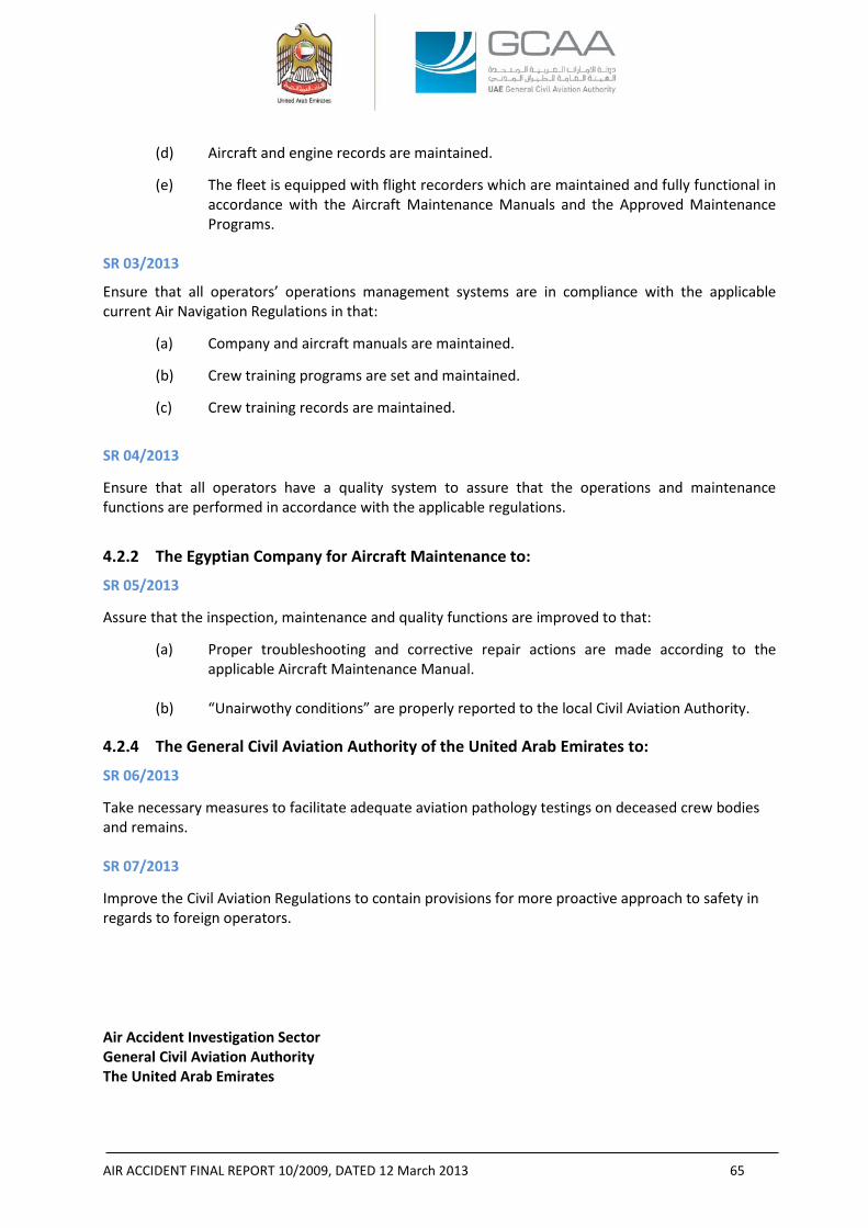
AIR ACCIDENT FINAL REPORT 10/2009, DATED 12 March 2013 65
(d) Aircraft and engine records are maintained.
(e) The fleet is equipped with flight recorders which are maintained and fully functional in accordance with the Aircraft Maintenance Manuals and the Approved Maintenance Programs.
SR 03/2013
Ensure that all operators’ operations management systems are in compliance with the applicable current Air Navigation Regulations in that:
(a) Company and aircraft manuals are maintained.
(b) Crew training programs are set and maintained.
(c) Crew training records are maintained.
SR 04/2013
Ensure that all operators have a quality system to assure that the operations and maintenance functions are performed in accordance with the applicable regulations.
4.2.2 The Egyptian Company for Aircraft Maintenance to:
SR 05/2013
Assure that the inspection, maintenance and quality functions are improved to that:
(a) Proper troubleshooting and corrective repair actions are made according to the applicable Aircraft Maintenance Manual.
(b) “Unairwothy conditions” are properly reported to the local Civil Aviation Authority.
4.2.4 The General Civil Aviation Authority of the United Arab Emirates to:
SR 06/2013
Take necessary measures to facilitate adequate aviation pathology testings on deceased crew bodies and remains.
SR 07/2013
Improve the Civil Aviation Regulations to contain provisions for more proactive approach to safety in regards to foreign operators. Air Accident Investigation Sector General Civil Aviation Authority The United Arab Emirates
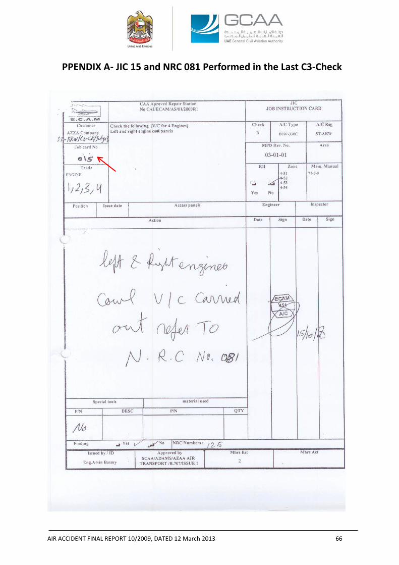
AIR ACCIDENT FINAL REPORT 10/2009, DATED 12 March 2013 66
PPENDIX A- JIC 15 and NRC 081 Performed in the Last C3-Check
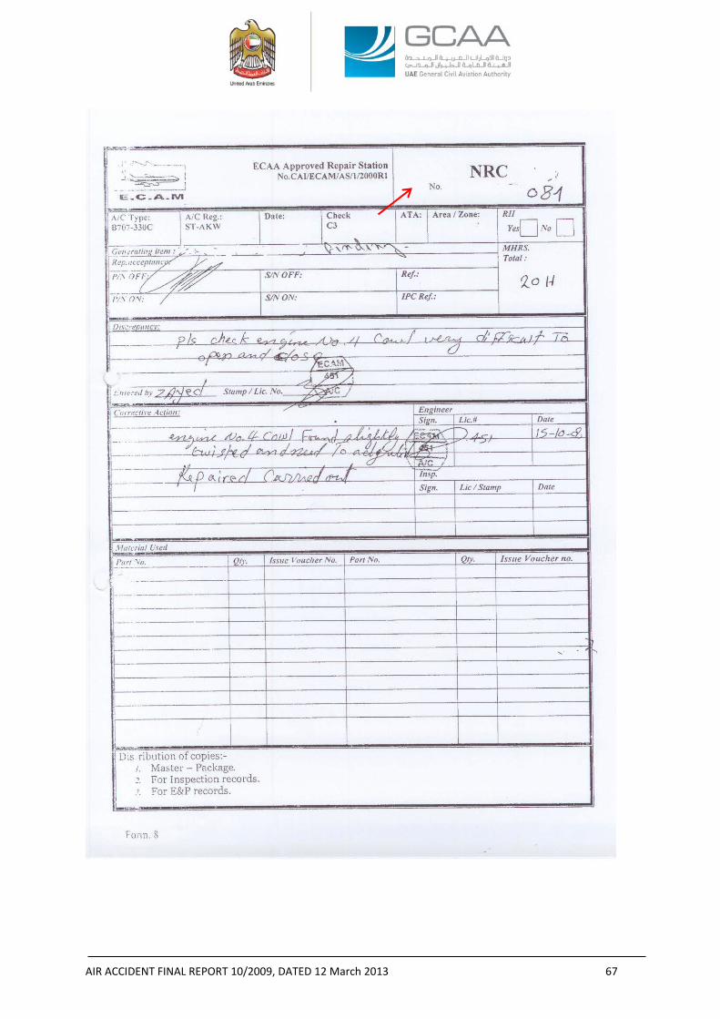
AIR ACCIDENT FINAL REPORT 10/2009, DATED 12 March 2013 67
AIR ACCIDENT FINAL REPORT 10/2009, DATED 12 March 2013 68
APPENDIX B- RIC 05 Performed in the Last B-Check
AIR ACCIDENT FINAL REPORT 10/2009, DATED 12 March 2013 69
APPENDIX C- Part of the Egyptian Aircraft Accident Investigation Directorate Response to the Draft Final Report to be Appended to the
Final Report NOTE 1: The below paragraphs are quoted from a letter received from the Egyptian Aircraft Accident Investigation Directorate containing comments forwarded by the Egyptian Civil Aviation Authority to be appended to the Final Report. NOTE 2: Sections 2.1 and 2.5 in this Report are amended after the Egyptian Aircraft Accident Investigation Directorate letter. A- From the report of accident
In paragraph “2.1 NO. 4 ENGINE COWLS”
The No. 4 engine cowls exhibited repairs that were not to the quality of aviation standards. Review of the maintenance records provided no information on when, where, and in accordance with what documents the repairs were performed. Due to the aged appearance of the cowls latches repairs, they were, most probably, not new or temporary repairs and they were performed at earlier date to the last C-Check. As a further clue to the age of the chronic cowls opening and closing problems was the fatigue striations revealed on the upper mounting point fracture surface by the metallurgical forensic examination which was consistent with a pre-existing fatigue condition.
During the Aircraft’s last C-Check in ECAM, the inspection task (RIC No.15) called for visual check of No. 4 engine LH and RH cowls, accordingly NRC No. 081 was raised by the inspection personnel stating that he experienced difficulties in properly aligning and latching the No. 4 engine cowls. Maintenance personnel interpreted the misalignment due to a twist in the cowl and a slight adjustment was needed whereas he, most probably, did not identify the existing latch old out-of-standard repairs and then realize that the adjustment was not the only proper corrective action to the chronic historical defect.
The multiple double holes and alignment pin indents in the RH cowl latch line, and bent and distorted alignment pins and U-bolt receptacles indicate that the cowl misalignment was not new and that closing and latching of the two mating cowl halves required more force and manipulation than normally specified in the AMM 71-5-21, page 205. Furthermore, after reviewing the maintenance records and interviewing the maintenance personnel, the Investigation found no evidence of that the problems associated with the No. 4 engine cowls were ever communicated to maintenance department requesting assistance and corrective actions.
And then in paragraph “2.5 MAINTENANCE MANAGEMENT”
Although the Aircraft had made 340 flight hours after the last C-Check, and 164 Preflight Checks, 163 Transit Checks, 8 A-Checks, and 1 B-Check were performed on the Aircraft between the last C-Check and the date of the Accident; the cowls’ chronic defect was not entered into any of the Aircraft records and the only recorded maintenance action was performed at ECAM through NRC sequential No. 81 where the entry was to “check engine No. 4 cowl, very difficult to open and close” , the corrective action was “Engine No. 4 cowl found slightly twisted and need to be adjusted, repair carried out”.
The post-Accident cowls’ forensic examination revealed that the repairs performed on the latch and cowls’ hinge support structure and the subsequent difficulty in opening and closing the cowls had, most probably, existed before the last C-Check, accordingly the Investigation believes that the adjustment
AIR ACCIDENT FINAL REPORT 10/2009, DATED 12 March 2013 70
was not the only repair action that should have been performed at that time. Deeper inspections and troubleshooting should have been performed before the closure of the routine card finding.
Furthermore, the abnormal repair of the cowls should have required ECAM to submit an “unairworthy conditions” report to the Egyptian Civil Aviation Authority according to the applicable Approved Maintenance Organizations Civil Aviation Regulations.
The cowls’ hinge support structure showed haphazard and below aviation standards repairs. The welding and the missing roller were examples that the support structure was exposed to stresses that were not supposed to be existing.
Then in paragraph “3.2 FINDINGS”
(h) The No. 4 engine cowls defect was chronic and, most probably, exited before the last C-Check.
(i) The maintenance and inspection functions performed in the last C3-Check were not sufficient to correct the historical damage to the No. 4 engine cowls caused by improper repetitive opening and closing.
(j) The maintenance organization, where the last C3-Check was performed, lacked a quality system that assures “unairworthy conditions” are reported to the local Civil Aviation Authority.
In paragraph “3.2 CONTRIBUTING FACTORS TO THE ACCIDENT
(c) the failure of the inspection and maintenance systems’ of the maintenance organization, which performed the last C-Check, to address, and appropriately report, the damage of the No. 4 engine cowls latches prior to issuing a Certificate of Release to Service;
And in paragraph “4.4 FINAL REPORT SAFETY RECOMMENDATIONS” The Egyptian Company for Aircraft Maintenance to:
SR xx/2012
Assure that the inspection and maintenance functions are improved to that:
(a) Proper troubleshooting and corrective repair actions are made according to the applicable Aircraft Maintenance Manual.
(b) “Unairwothy conditions” are properly reported to the local Civil Aviation Authority.
B- ECAA comments on all of the above
All of the above paragraphs are coming from assuming (without evidence) that damage of the engine no. 4 cowl are before the last C check carried out by ECAM company (which ended in 2/2/2009),
However, by reviewing the work package of last B Check (which ended in 25/7/2009 and provided to ECAA from the investigation committee), there was a Routine Inspection Card (3-1-1) for Zone of Engine no. 4 state that “Check L/R engine cowl panels, access panel, hook latch fasteners cowl panel support rod for condition, missing items & security”
In the action taken “Checked and necessary repairs C/O”
And from this task it is showing that
AIR ACCIDENT FINAL REPORT 10/2009, DATED 12 March 2013 71
• There were damages found in these areas during the B check.
• There is no NRC (Non Routine Card) raised from this task and no details about the damage and repairs done in these areas which indicate the careless of repair of this area. While in the last C check when a damage found in the Engine cowl, NRC raised and define the damage and the repair done as follow (check No. 4 engine cowl very difficult to open and close) and the corrective action was (No. 4 engine cowl found slightly twisted and need to be adjusted. Repaired carried out).
• This record indicates that the damage is found after the last C- check and not before as mentioned in the report. And according to that there was no need for ECAM to make an unairworthy condition report which was not found during the last C check.
• There is no indication “in the report” to the record of B check which carried out in Sudan under the quality of AZZA company and contain a repair in the area of engine 4 cowl.
-END-
AIR ACCIDENT FINAL REPORT 10/2009, DATED 12 March 2013 72
APPENDIX D- Pratt & Whitney Report No. 9417, Dated 20 April 2011
“Sequence of Events for Sudan Airways B707 ST-AKW No. 4 Powerplant Core Thrust Reverser Post-Impact Deployment”
Pratt & WhitneyFlight Safety Office400 Main StreetM/S 169-10East Hartford, CT USA 06108
Per Annex 13 to the Convention on International Civil Aviation, the information presented here, inclusive ofany enclosures, is for investigative purposes only.
Page 1 of 1
26 February 2013P&W FSO Investigation Number: 9417
Jean-Pierre ScarfoAerospace Engineer, PowerplantsOffice of Aviation SafetyAviation Engineering Division (AS-40)U.S. National Transportation Safety Board490 L’Enfant Plaza East, S.W.Washington, DC USA 20594-2000
Subject: Revised No. 4 Engine Core Thrust Reverser Deployment Sequence Report
Reference(s): [1] Sudan Airways (SUD) Pratt & Whitney (P&W) JT3D-3B powered Boeing B707-330C, TheRepublic of Sudan Registration ST-AKW, accident during Initial Climb from SharjahInternational Airport (SHJ) in Sharjah, United Arab Emirates (UAE) on 21 October 2009.
[2] Memo from Pratt & Whitney (Douglas Zabawa) to NTSB (Jean-Pierre Scarfo) with Subject:‘No. 4 Engine Core Thrust Reverser Deployment Sequence’ dated 20 April 2011.
Dear Mr. Scarfo,
This correspondence is covered by U.S. Department of Commerce, Bureau of Industry and Security (BIS), exportlicense No. D483350, and U.S. Department of Treasury, Office of Foreign Asset Control (OFAC) export licenseNo. MUL-300-a.
Thank you for inviting Pratt & Whitney’s participation in the investigation of the Reference [1] accident as aTechnical Advisor to the U.S. National Transportation Safety Board Accredited Representative.
Please find enclosed Revision 1 of the Airplane Accident Powerplant Report that was originally transmitted via theReference [2] memo. The Revisions to the report include a change to the footnote that removes restrictionsrelative to public distribution of the report and a revision of the Export Control classification that more accuratelyreflects the lack of Technical Data in the report itself. These revisions are intended to allow the UAE to includethe enclosed report as part of their Final Report of the Reference [1] accident.
This document contains no Technical Data subject to the EAR or ITAR.
Should you have any questions or further requests please contact me at the numbers below.
We look forward to continuing to work together in support of this aircraft accident investigation.
Best Regards,
______________________Douglas J. ZabawaPhone: +1(860)565-6034Cell: +1(860)805-1376E-mail: [email protected]
Encl: SUD B707 ST-AKW No. 4 TR Sequence Revision 1.pdfcc: Pratt & Whitney FSO Investigation File No. 9417
P&W FSO #9417 Page 1 of 12
Per Annex 13 to the Convention on International Civil Aviation, the information presented here is for investigative purposes only.
_________________________________________________________________________________
Airplane Accident Powerplant Report
AZZA TransportOperated by Sudan AirwaysBoeing B707-330C, Registration No. ST-AKWPowered by Pratt & Whitney JT3D-3B PowerplantsNo. 4 Engine, Serial No. 644495Sharjah, UAE21 October 2009
This document contains no Technical Data subject to the EAR or ITAR
Pratt & WhitneyFlight Safety OfficeLog No. 9417Report Date: 20 April 2011Revision 1: 26 February 2013Reasons for Revision: Annex 13 footer and Export Control classification notes revised
________________________________________________________________________
Pratt & WhitneyFlight Safety Investigations400 Main Street M/S 169-10East Hartford, CT USA 06108
P&W FSO #9417 Page 2 of 12
Per Annex 13 to the Convention on International Civil Aviation, the information presented here is for investigative purposes only.
Sequence of events for Sudan Airways B707 ST-AKW No. 4 powerplant core ThrustReverser post-impact deployment
Hardware observations supporting the following sequence of events can be found in theField Notes for the No. 4 Engine & Core Thrust Reverser Examination for SUD JT3D-3Bpowered B707-330C ST-AKW 21 October 2009 Takeoff Accident at Sharjah, UAE dated02 – 06 August 2010.
Discussion:
As observed from the airport security camera, the accident airplane impacted the groundat a steep angle in a nose down and right wing down attitude. At this point the No. 4powerplant core Thrust Reverser (T/R) was in the stowed position. Due to the airplaneorientation at impact and the component inertia, the translating sleeve translated forwardand the clam shell halves rotated past their normally stowed position (over-stowposition). This motion resulted in interference between the aft lip of the T/R forward sealand the Leading Edge (LE) of the clam shell door halves. It was this interaction that ledto the observed deformation/crushing/buckling of the aft lip of the forward T/R seal andthe buckling of the clam shell door halves that was biased to the LE, see Photos (1) and(2). It was the forward motion in the over-stowed direction of the core T/R hardware thatwould have placed the T/R follow-up control rods, located on the top1 of the powerplant,in compression and most likely led to their bent condition observed during the engineexamination.
The deformation and tensile/bending overload fracture of the lower left adjustment linkbetween its hinge drive idler and outer crank most likely occurred during this initialimpact sequence when the core T/R was moving forward to the over-stow position. Theforward rotation of the left clam shell was arrested due to interference with the aft lip ofthe T/R forward seal thus stopping the rotation of the lower outer crank. The translatingsleeve, due to its inertia, continued to translate forward rotating the lower left hinge driveidler. With the lower left hinge drive idler intact and the lower outer crank intact andsecured to the left clam shell half (whose motion had been arrested), the lower leftadjustment link bent and then fractured as the translating sleeve continued to moveforward. The orientation of the bend in the lower left adjustment link was consistent withthis scenario, see Photo (3).
The upper left adjustment link was intact and not deformed; however its associated innerhinge shaft and drag link were both fractured, see Photo (4). The undeformed upper leftadjustment link indicated that the fracture of the upper left drag link occurred prior to thebending/fracture of the lower left adjustment link. If the upper left drag link had beenintact when the T/R translating sleeve was driven to its most over-stowed position, theupper left adjustment link would have been bent, if not fractured, similar to what wasobserved on the lower left adjustment link. With the upper left drag link fractured theinertia of the T/R translating sleeve could not be transferred through the upper left
1 All directional references are aft looking forward with the engine in its normally installed position on theairplane.
P&W FSO #9417 Page 3 of 12
Per Annex 13 to the Convention on International Civil Aviation, the information presented here is for investigative purposes only.
linkage to the left clam shell half and thus the loading was not present to bend the upperleft adjustment link in the same manner as that observed on the lower left adjustmentlink. It is noted that the undeformed upper left adjustment link could also be explainedby fracture of the upper inner hinge shaft, however, metallurgical examination identifiedthe fracture mode of this part as being tensile. Under the loading in this scenario theupper inner hinge shaft would have been in torsion/shear. The finding of a tensilefracture indicated that this part most likely fractured later in time due to a loading thathad a component normal to the engine centerline and was located towards the end of theupper inner hinge shaft crank arm. This loading would have produced a moment on thehinge shaft which would have resulted in the tensile loading inferred from the nature ofthe fracture.
The core T/R remained in the over-stowed position as the No. 4 powerplant separatedfrom the airplane during the accident sequence. At some point after separation, andbefore it came to rest, the powerplant impacted a hard surface, most likely the road thatran through the accident site, on its top side. It is this impact that resulted in the scrapemarks and damage to the aft end of the translating sleeve main pylon fairing and theupper translating sleeve actuators. The location of the scrape marks was consistent withthe translating sleeve being in the stowed position at this point in time as indicated by thefinding that in the deployed position there was an undamaged area of the pylon fairingseparating two similarly damaged areas, but in the stowed position, the two similarlydamaged areas aligned, see Photo (5).
The hard impact to the top of the powerplant described above would have acted in thedirection (radially inwards) that would have driven the lower locking rollers (attached tothe translating sleeve) downwards past the J-hook locks (part of the actuating cylindersthat are attached to engine) effectively disengaging the T/R locking mechanism. Thiswould have removed the restraint that prevented translating sleeve aft movement. Scrapemarks on the upper actuator cylinder body exhibited axial and tangential componentswhich, if in the aft/inboard direction, would have acted to push the translating sleevetowards the deploy position at a time when the J-hook lock was disengaged, see Photo(6).
The material deformation and interference between the left clam shell door and the aft lipof the forward T/R seal was sufficient to jam this clam shell half in place. As thetranslating sleeve was being forced towards the deploy position, this jamming createdenough resistance that the lower left drag link fractured in tension, see Photo (7). Theloading in this drag link may have been increased due to it being the only membercarrying load between the translating sleeve and the left clam shell door, a result of thepreviously described fracture of the upper left drag link.
The translating sleeve continued to move towards the deployed position. With thelinkages intact between the translating sleeve and the right clam shell, see Photos (8) and(9), (and the right clam shell not jammed in the over-stowed position) the right clam shellrotated towards the deployed position. It was during this time that the lower rightactuator rod contacted the lock pivot bolt, see Photo (10), creating the observed witness

P&W FSO #9417 Page 4 of 12
Per Annex 13 to the Convention on International Civil Aviation, the information presented here is for investigative purposes only.
mark along the length of the rod, see Photo (11). At this point the powerplant came to restat the accident scene with the translating sleeve and right clam shell in the deployedposition and the left clam shell jammed in the over-stowed position.
Additional indications that the core T/R was stowed at the time of impact were found inthe condition of the upper and lower actuators and their associated rods, see Photos (12)and (13). In the deployed position, the actuator rods are extended. The nature of theairplane impact (high impact angle, nose down attitude) would have put these rods incompression due to the inertial loading from the translating sleeve and would havechallenged the mounting of the actuator cylinders. Since the impact was not purely axialrelative to the powerplant the loading of the translating sleeve on the actuator rods wouldhave been eccentric, a condition that would have exacerbated any tendency for the rods tobuckle and would have also introduced a torsional load on the actuator mounts. If therods were extended at this time it is expected that buckling of the rods would have beenobserved in the hardware or both sets of actuator cylinders would have separated fromtheir mounts and been significantly displaced. The lack of buckling of the actuator rodshas been interpreted to further support that the core T/R was stowed at the time of impact.While the upper actuators were separated from the engine they were still in theirapproximate correct position and the lower actuators were still secured to the engine withbuckling noted only to the aft bracket braces. The upper cylinders did receive a directimpact with the ground, which may explain why their mounting was compromised. Thebuckling of the lower cylinder aft bracket braces was still consistent with the nature ofthe loading during the accident sequence.
P&W FSO #9417 Page 5 of 12
Per Annex 13 to the Convention on International Civil Aviation, the information presented here is for investigative purposes only.
Conclusion:
Given the above discussion, the following is a summary of the sequence of events:
1. The airplane impacted the ground in a nose down, right wing down attitude, the No. 4powerplant T/R was in the stowed position.2. The core T/R, due to the inertia of the translating sleeve and clam shell halves, movedpast the stowed position (over-stowed).3. The follow-up control rods on the top of the powerplant bent.4. The clam shells interacted with the T/R forward seal causing material deformation; theleft clam shell became jammed in position.5. The upper left drag link fractured.6. The lower left hinge drive idler to outer crank adjustment link bent and fractured.7. The powerplant completed its separation from the airplane and contacted the road onits upper side pushing the translating sleeve downwards and moving the lock roller out ofengagement with the lock J-hooks.8. The axial/tangential loads (indicated by scrape marks on the top of the powerplant)acted to move the translating sleeve aft.9. The lower left drag link fractured completing the decoupling of the translating sleevefrom the left clam shell half (the upper left drag link fracture was the other half of thisdecoupling).10. The lower right actuator rod contacted the lock pivot bolt.11. The translating sleeve moved to the deployed position rotating the right clam shellinto the deployed position also.12. The powerplant came to rest at the accident site.
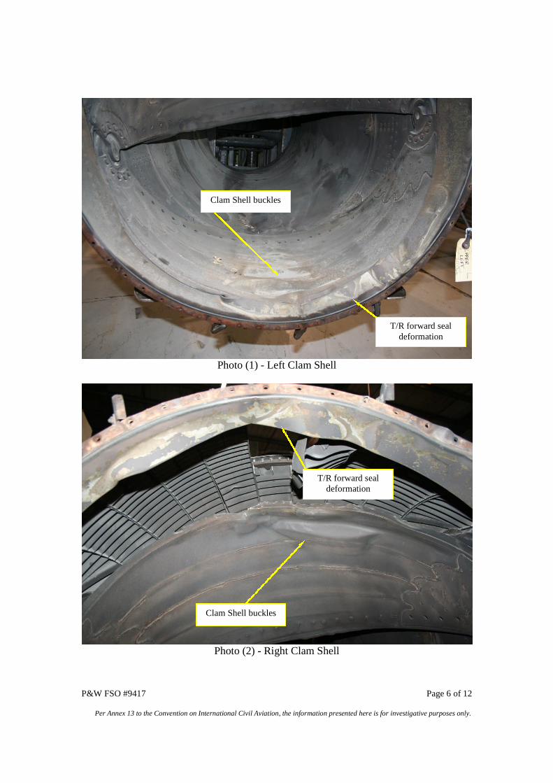
P&W FSO #9417 Page 6 of 12
Per Annex 13 to the Convention on International Civil Aviation, the information presented here is for investigative purposes only.
Photo (1) - Left Clam Shell
Photo (2) - Right Clam Shell
T/R forward sealdeformation
Clam Shell buckles
Clam Shell buckles
T/R forward sealdeformation
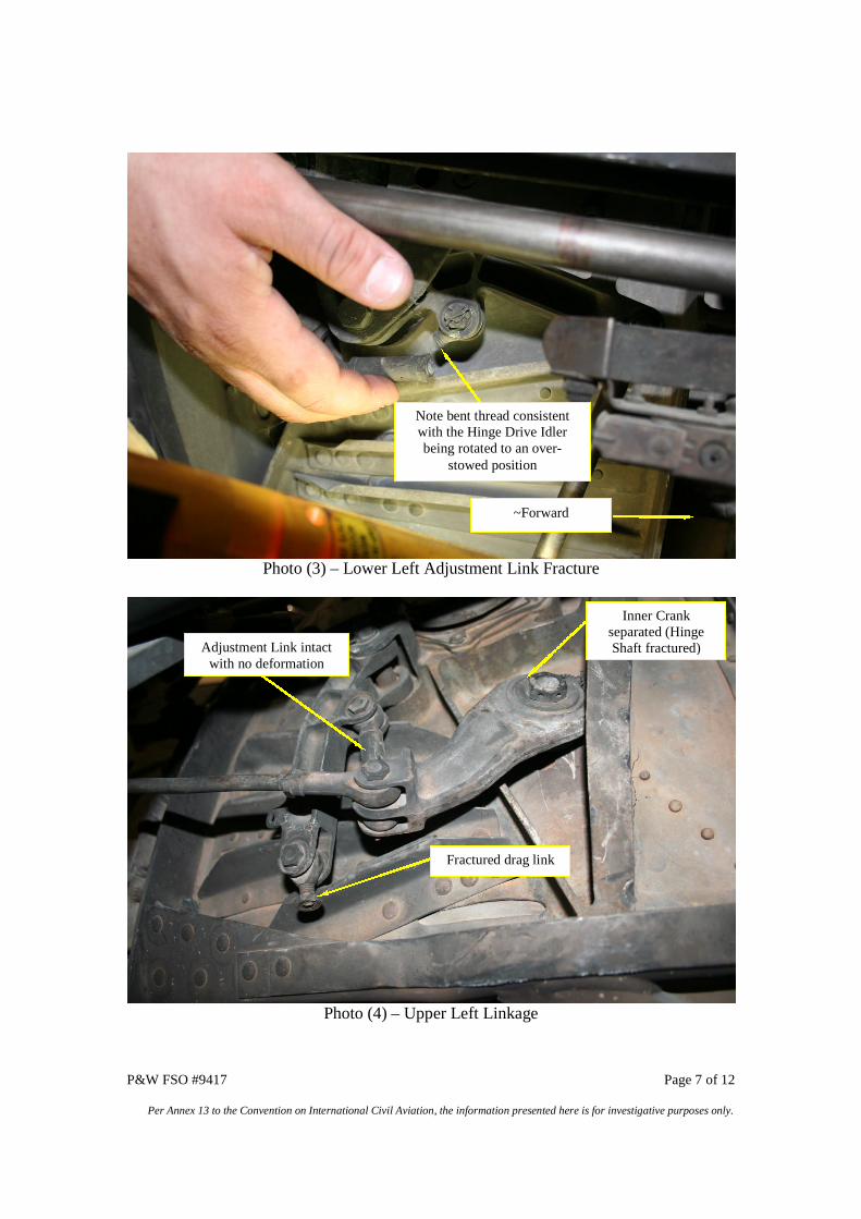
P&W FSO #9417 Page 7 of 12
Per Annex 13 to the Convention on International Civil Aviation, the information presented here is for investigative purposes only.
Photo (3) – Lower Left Adjustment Link Fracture
Photo (4) – Upper Left Linkage
~Forward
Note bent thread consistentwith the Hinge Drive Idlerbeing rotated to an over-
stowed position
Inner Crankseparated (HingeShaft fractured)Adjustment Link intact
with no deformation
Fractured drag link
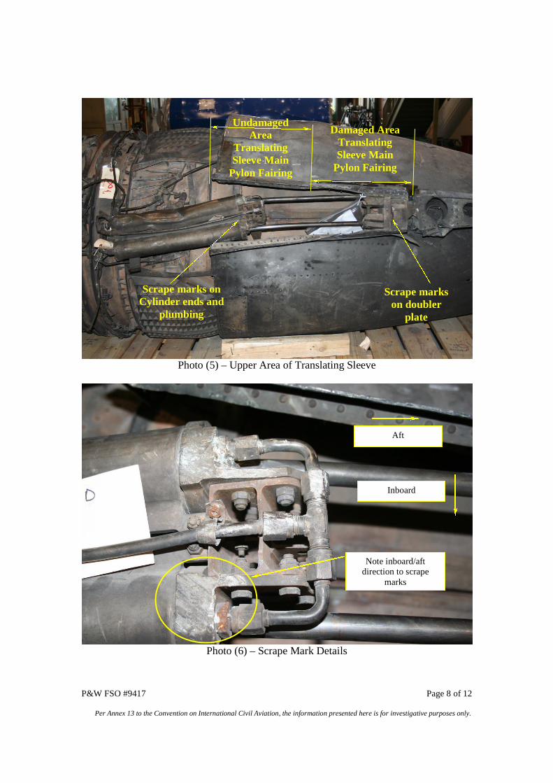
P&W FSO #9417 Page 8 of 12
Per Annex 13 to the Convention on International Civil Aviation, the information presented here is for investigative purposes only.
Photo (5) – Upper Area of Translating Sleeve
Photo (6) – Scrape Mark Details
Scrape markson doubler
plate
Scrape marks onCylinder ends and
plumbing
UndamagedArea
TranslatingSleeve Main
Pylon Fairing
Damaged AreaTranslatingSleeve Main
Pylon Fairing
Aft
Inboard
Note inboard/aftdirection to scrape
marks
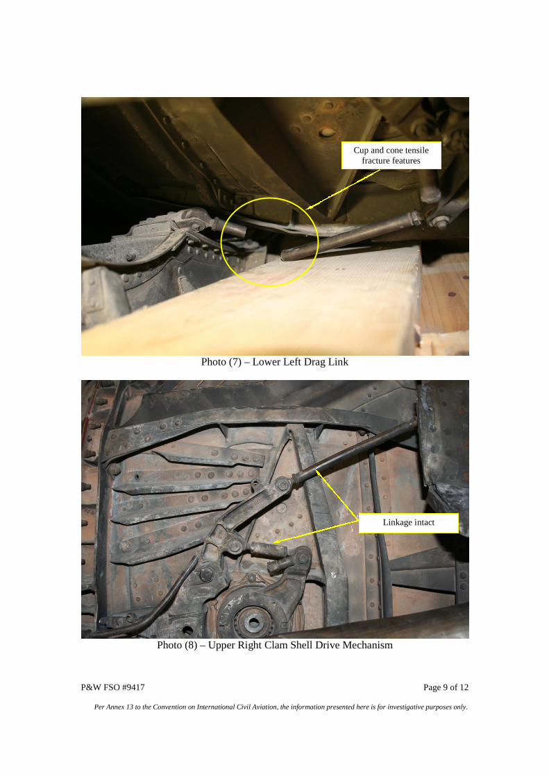
P&W FSO #9417 Page 9 of 12
Per Annex 13 to the Convention on International Civil Aviation, the information presented here is for investigative purposes only.
Photo (7) – Lower Left Drag Link
Photo (8) – Upper Right Clam Shell Drive Mechanism
Cup and cone tensilefracture features
Linkage intact
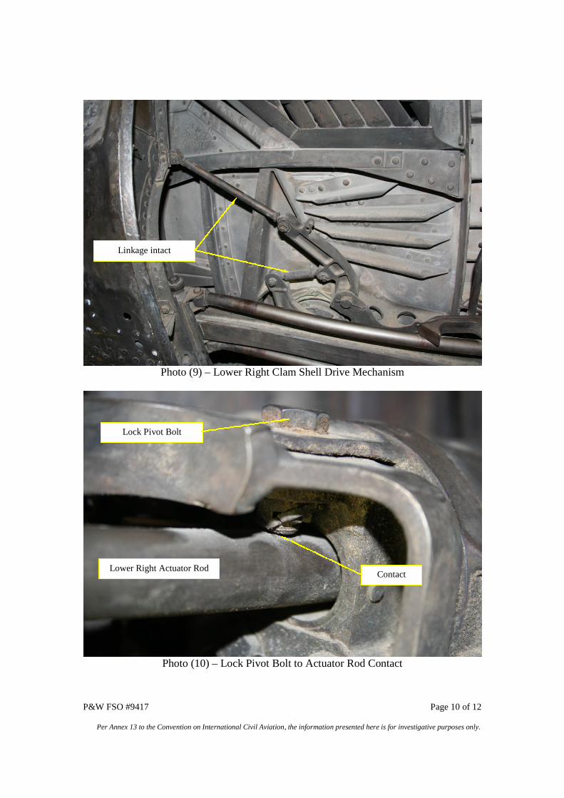
P&W FSO #9417 Page 10 of 12
Per Annex 13 to the Convention on International Civil Aviation, the information presented here is for investigative purposes only.
Photo (9) – Lower Right Clam Shell Drive Mechanism
Photo (10) – Lock Pivot Bolt to Actuator Rod Contact
Linkage intact
Lower Right Actuator Rod
Lock Pivot Bolt
Contact
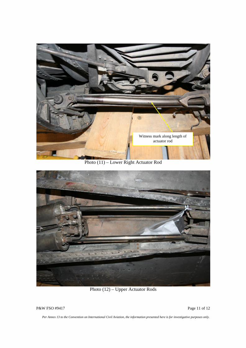
P&W FSO #9417 Page 11 of 12
Per Annex 13 to the Convention on International Civil Aviation, the information presented here is for investigative purposes only.
Photo (11) – Lower Right Actuator Rod
Photo (12) – Upper Actuator Rods
Witness mark along length ofactuator rod
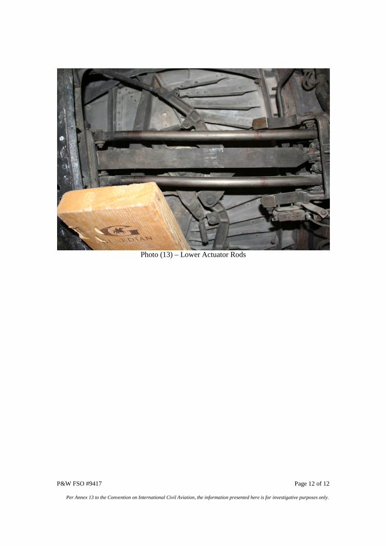
P&W FSO #9417 Page 12 of 12
Per Annex 13 to the Convention on International Civil Aviation, the information presented here is for investigative purposes only.
Photo (13) – Lower Actuator Rods