Embed Size (px)
Citation preview
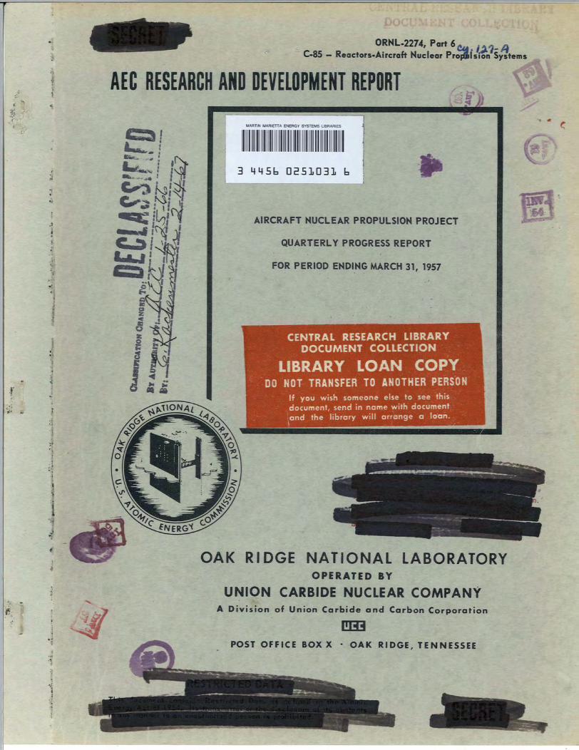
ORNL-2274, Port 6C-85 - Reactors«Aircrof> Nuclear Propulsion Systems
This document consists of 52 pages.
Copy [3-1 of 226 copies. Series A.
Contract No. W-7405-eng-26
AIRCRAFT NUCLEAR PROPULSION PROJECT
QUARTERLY PROGRESS REPORT
For Period Ending March 31, 1957
W. H. Jordan, DirectorS. J. Cromer, Co-Director
A. J. Miller, Assistant Director
DATE ISSUED
JUL2 2iqfi7
OAK RIDGE NATIONAL LABORATORY
Operated byUNION CARBIDE NUCLEAR COMPANY
A Division of Union Carbide and Carbon CorporationPost Office Box X
Oak Ridge, Tennessee
3 M45b QS51D31 b
1. R. G. Affel
2. C. J. Barton
3. M. Bender
4. D. S. Billington5. F. F. Blankenship6. E. P. Blizard7. C. J. Borkowsk
8. W. F. Boudreau
9. G. E. Boyd10. M. A. Bredig11. E. J. Breeding12. W. E. Browning
F. R. Bruce
A. D. Callihan
D. W. Cardwell
Center (K-25)Charpie
13.
14.
15.
16.
17.
18. R. L. Clark
19. C. E. Clifford
20. J. H. Coobs
21. W. B. Cottrell
22. D. D. Cowen
S. Cromer
R. S. Crouse
F. L. Culler
D. R. Cuneo
J. H. DeVan
L. M. Doney29. D. A. Douglas30. E. R. Dytko
W. K. Eister
L. B. Emlet (K,D. E. FerguA. P. Fraas
J. H. FryeW. T. Fu
R. J. Gray38. A. T. Gres
39. W. R. Grim
40. A. G. Grin
41. E. Guth
42. C. S. Han
43. E. E. Ho
44. H. W. Ho|45. A*HolH46. A.' S. H
C. E.
R. A.
23.
24.
25.
26.
27.
28.
31.
32.
33.
34.
35.
36.
37.
ORNL.2274, Part 6- Reactors-Aircraft Nuclear Propulsion Systems
J. T. Howe
W. H. Jordan
G. W. Keilholtz
C. P. Keim
F. L. Keller
M. T. KelleyF. Kertesz
J. J. KeyesE. M. KingJ. A. Lane
R. B. Lindauer
S. LivingstonN. LyonG. MacPherson
E. MacPherson
C. Maienschein
W. D. ManlyE. R. Mann
L. A. Mann
W. B. McDonald
J. R. McNallyF. R. McQuilkin
R. V. MeghreblianR. P. Milford
A. J. Miller
R. E. Moore
J. G. MorganK. Z. MorganE. J. MurphyJ. P. Murray (Y-12)M. L. Nelson
G. J. Nessle
R. B. Oliver
L. G. Overholser
P. Patriarca
S. K. PennyA. M. PerryJ. C. PiggP. M. ReylingA. E. Richt
M. T. Robinson
H. W. SavageA. W. Savolainen
R. D. Schultheiss
ScotfL. |cott

94. E. D. Shit ley95. A. Simon 1
96. 0. Sismanl
97. J. Sites 198. M. J. Skmrlr99. A. H. Snelll
100. C. D. Susans
101. J. A. Swartolt
102. E. H. Taylor!103. R. E. Thomal
104. D. B. Trauger
105. D. K. Trubey106. G. M. Watson
AFPI
AF PI
AF Pla
AF Plan'AF Plan
AF Plant
AF Plant
AF Plant
Air Res
AirTe
Air UjrfwersAN(^ProjectArgMne Nati
ed Forces
ned Forces
Assistant AF P'
rAssistant Sec reAtomic EnergyBureau of Aerona
Bureau of Aerona
107. A. M. WeJRberg108. J. C. VHte
109. G. D. Jfhitman
110. E. Panigner (consultant)111. G. #Williams112. ±M Wilson
113. CPE. Winters114. Mlobe\
115-117J ^>RNL - Y-12 Technical LibraryDocument Reference Section
118-jJT Laboratory Records DepartmentMb. Laboratory Records, ORNL R. C
Ijffl28. Central Research Library
[EXTERNAL DISWBUTION
t Representee, BaltimoreRepreseoflTtive, BurbankRepres^rative, Clifton[Repre^Rtative, Long Beach
epnWentative, MariettaenVsentative, Santa Monica
esentative, Seattleresentative, Wichitaand Development Command (RDGN)Intelligence CenterLibraryffice, Fort Worth,al Laboratory
cial Weapons Project, Sandia[ecial Weapons Project, Washingtonmt Representative, Downeyy of the Air Force, R&D
ssion, Washingtoncs
cs General RepresentativeChicago Operation*OfficeChicago Patent GraspChief of Naval Research
Convair-General DyCurtiss-Wright CorpGeneral Electric Co
Hartford Area Office
Headquarters, Air ForIdaho Operations OffiLock Iand Area Office
Los Alamos Scientific laboratoryMarquardt Aircraft ComAny
imics Corporationition
ny (ANPD)
Special Weapons Center
175.
176.
177-179.
180.
181.
182.
183.
184.
185.
186-189.
190.
191.
192.
193.
194.
195.
196.
197.
198-215.
216-225.
226.
National Advisoly Committee fa^Jferonautics, ClevelandNational Advisoly Committee^^Aeronautics, WashingtonNaval Air Development andJ^Tterial CenterNaval Research I-aboratonrfNorth American Eviation^Rc. (Missile Development Division)Nuclear Development CaBoration of AmericaOffice of Chief olNavaWOperations (OP-361)Patent Branch, WfchjptonPatterson-Moos
raft Division (Fox Project)ttions Office
Pratt & Whitney ASan Francisco Op^Sandia CorporatSandi a Corpora(School of AviabbnUSAF HeadqjBFtersUSAF Proj^RANDU. S. NavdWiadiologUniversitflDf Califon
Wright AwDevelopmeTechniAT InformationDivisiawof Research
ivermore
dicine
:al Defense LaboratoryRadiation Laboratory, LivermoreCenter (WCOSI-3)
[ervice Extension, Oak Ridgeid Development AEC, ORO
FOREWORD
This portion, Part 6. Advanced Power Plant Design and Aircraft Shielding, of theAircraft Nuclear Propulsion Project Quarterly Progress Report falls in AEC categoryC-85, Reactors - Aircraft Nuclear Propulsion Systems, and is therefore being issuedseparately in order not to further limit distribution of the material that falls in AECcategory C-84, Reactors - Special Features of Aircraft Reactors, which has been issuedas ORNL-2274, Parts 1-5.
rid ••;?'*£*•

fs
CONTENTS
FOREWORD v
SUMMARY !
PART 6. ADVANCED POWER PLANT DESIGN AND AIRCRAFT SHIELDING
6.1. ADVANCED POWER PLANT DESIGN 5
A Nuclear-Powered Transport Type of Aircraft with Turboprop Engines 5Airframe 5
Engines 6
Reactor and Reactor Shield 9
Crew Shield 9
Chemical Auxiliary Engines 10
Weight and Payload Estimates 10
6.2. TOWER SHIELDING FACILITY H
Irradiation of a Pratt &Whitney Aircraft J-57 Engine ]]
Experimental Arrangement During the Irradiation 11
Gamma-Ray and Neutron Dose-Rate Measurements Preceding and During theEngine Exposure (Phases I and II) 11
Gamma-Ray Dose-Rate Measurements After Engine Exposure (Phase III) 12
Gamma-Ray Spectra Measurements After Engine Exposure (Phase III) 15
Analysis of Results 19
6.3. BULK SHIELDING FACILITY 21
Preliminary Measurement of the Spectrum of Prompt Gamma Rays fromThermal Fission of U235 21
Experimental Apparatus 21
Preliminary Instrument Tests 21
Future Work 23
Analysis of the Fission-Product Gamma-Ray Energy Spectrum Experiment 23
After-Shutdown Gamma-Ray Dose Measurements 23
Feasibility Study of a Circulating-Fuel Reactor for Shielding Tests 25
Program for Shielding Measurements at the ART 25
Total Absorption Gamma-Ray Spectrometer 25
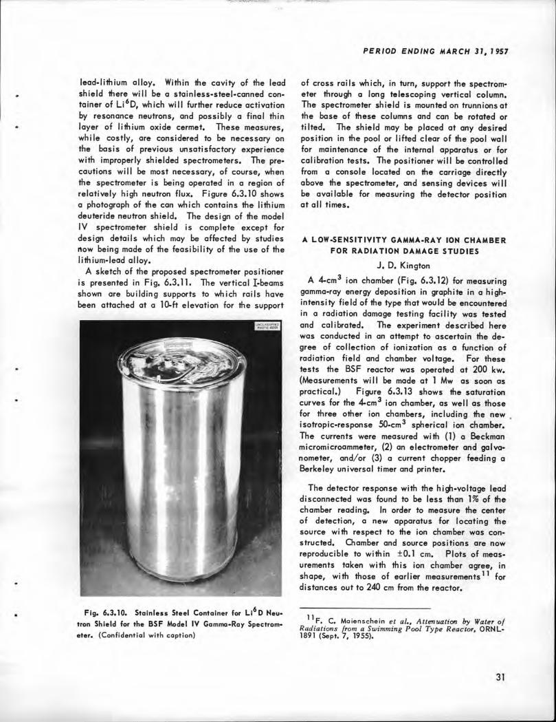
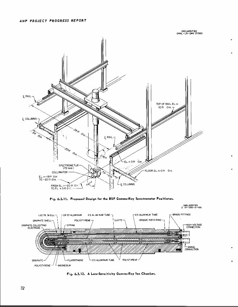
The BSF Model IV Gamma-Ray Spectrometer Housing and Positioner 27
A Low-Sensitivity Gamma-Ray Ion Chamber for Radiation Damage Studies 31Pulsed-Neutron Method for the Determination of Neutron Diffusion Parameters
in Beryllium 33
A U02-Stainless Steel Shield Test Reactor for the BSF 34Description of the Reactor 34
Heat Transfer Calculations 37
Reactivity Calculations 38
Control Plate Experiments 41
VI II
ANP PROJECT QUARTERLY PROGRESS REPORT
SUMMARY
6.1. Advanced Power Plant
The results of a preliminary investigation indicate that the presently flying Douglas C-133A aircraft could be adapted for all-nuclear-poweredflight with the use of a reflector-moderated circulating-fuel reactor of the ART type in conjunctionwith turboprop engines. The gross weight of suchan aircraft, exclusive of payload but with shieldingsufficient to limit the maximum crew-compartmentdose rate to 0.02 rem/hr, would be approximately230,000 lb. The payload would be 25,000 to50,000 lb and would thus duplicate that of thepresent chemical-powered C-133A aircraft. Thepower of the reactor required for this applicationwould be about 75 Mw. Such an all-nuclear-powered aircraft would be suitable for a widevariety of applications, including logistics transport, early-warning radar missions, and missilelaunching.
6.2. Tower Shielding Facility
A test of the compatibility of a jet engine and areactor system was made with a Pratt & WhitneyAircraft J-57 model jet engine being operated continuously for 50 hr while it was exposed to-a totaltissue dose of 7 x 10 ergs/g from the TowerShielding Facility reactor. The objectives of theexperiment were to study effects of radiation on thecontrol and performance of the engine, the radiation damage to engine components, and the inducedradioactivation of the engine. Gamma-ray spectraand dose-rate measurements were taken immediatelyafter exposure and for several days following exposure in an attempt to identify the elements whichwere emitting induced radioactivity. The analysishas thus far resulted in the identification of 2.76-
and 1.38-Mev Na24 and 2.06-, 1.7-, and 0.83-MevMn gamma rays. A more detailed analysis is inprogress. No deleterious effects on the performanceof the engine were observed during the irradiation,and it has been returned to Pratt & Whitney Aircraftfor radiation damage studies.
6.3. Bulk Shielding Facility
Equipment has been developed to experimentallymeasure the prompt-gamma-ray spectrum resultingfrom the thermal fission of U , in order that anaccurate prompt-gamma-ray source term will beavailable for use in future calculations of the
performance of reactor shields. The equipmentconsists of a spiral fission chamber viewed by thecollimator of a multiple-crystal scintillation spectrometer. Gamma rays detected in the spectrometerare recorded if they are observed in time coincidence with the event in the fission chamber, withinthe experimental time resolution. This resolutionhas been narrowed to about 0.06 fzsec. Preliminaryinstrument tests have been performed, and it isfelt that only the linearity of the pulse analyzermust be improved before a satisfactory experimentcan be performed.
In the continued analysis of the fission-productgamma-ray spectrum experiment, efforts have beenconcentrated on correcting the data for the non-uniqueness of the scintillation spectrometers. Amethod designed to remove almost completely thenonuniqueness effect failed in that the final resultsappear to be meaningless. It is not yet clearwhether this failure was due to a mistake in execu
tion or to the propagation of experimental error.A preliminary experiment was performed to de
termine the after-shutdown gamma-ray dose emittedby the Bulk Shielding Facility reactor. In twoindependent tests, 24 hr apart, the reactor, whichwas loaded with fuel elements that contained
fission products from previous operations, wasoperated at 100 kw for 1 hr and gamma-ray dose-rate measurements were taken for approximately14 hr after shutdown. The results are presented.
A study was carried out to determine the feasibility of constructing a circulating-fuel reactor atthe BSF for aircraft shield tests. Three fuel
systems were considered, the most feasible ofwhich appeared to be a mixture of U02S02 dissolved in D20. Extensive nuclear calculations
'£ %1$'#^W*j$j
would be required to demonstrate the degree towhich such a fuel system would give a nuclearapproximation to the molten-salt system proposedfor aircraft propulsion.
Equipment is being assembled for calibrationand efficiency measurements in preparation forshielding measurements during operation of theART. In order to conform with the engineeringtest schedule on the pressure shell, this workmust be completed before December 1, 1957.
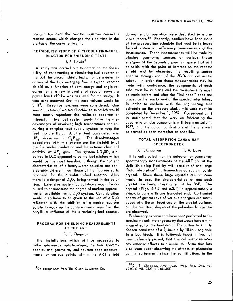
It is anticipated that the detector for gamma-rayspectroscopic measurements at the ART and theBSF will consist of one large total absorptionthallium-activated sodium iodide crystal. Sincethese large crystals are not commonly in use, thecharacteristics of a 9-in.-dia crystal are now beinginvestigated.
A housing which includes a tungsten collimatorand a lithium-lead shield is to be fabricated for
the BSF spectrometer. The lithium will be included in a shield in order to avoid backgroundeffects caused by neutron radiative capture in thematerials of the sodium iodide crystal which is tobe used as a spectrometer. The inner cavity ofthe housing will be lined with a layer of Li D tofurther reduce activation by resonance neutrons.A positioner is being developed which will supportthe 15-ton assembly and allow the spectrometercollimator to be positioned to within 1 cm of anydesired point in the pool at an angle known towithin a fraction of a degree.
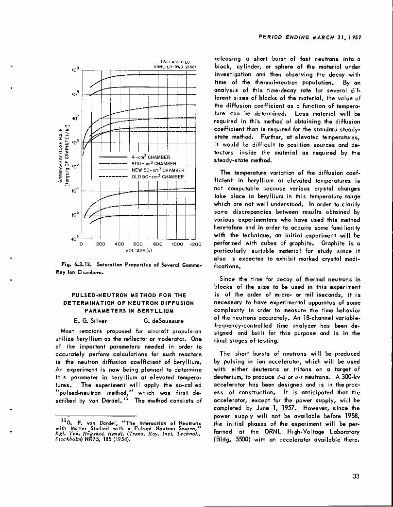
A 4-cm ion chamber designed for measuringgamma-ray energy deposition in graphite in a high-intensity field, such as that which would be encountered in a radiation damage facility, wastested and calibrated. For these tests the BSF
reactor was operated at 200 kw. Plots of measure
ments taken with this chamber agree in shape withthose of earlier measurements made with other
detectors for distances out to 240 cm from thereactor.
In order to accurately perform calculations forreactors in which beryllium is used as the reflectoror moderator, the neutron diffusion coefficient ofberyllium must be known. Equipment is now beingfabricated for an experiment which will utilize the"pu'sed-neutron method" to determine this coefficient as a function of temperature. This is notcomputable because various crystal changes takeplace in beryllium at elevated temperatures whichare not well understood. Preliminary experimentswill be performed with cubes of graphite, which isalso expected to exhibit marked crystal modifications.
Design and development of a U02-stainlesssteel reactor for the BSF are underway. Theproposed reactor, which will have a higher-energygamma-ray spectrum that will more nearly correspond to the leakage spectrum of the ART, willhave a near-cubical design that will be amenableto shield tests. The control system will utilizeplate-type control devices which will provide thedesired nearly symmetrical leakage flux. Severaldevelopment experiments for the control systemhave been performed. In addition, heat transferand reactivity calculations have been carried out.Several experiments have also been performed inthe present BSF uranium-aluminum reactor to determine the effects of inserting stainless steel orboron-loaded aluminum plates within the core. Theresults of these measurements are being used topredict the control that can be effected in a U02-stainless steel core.
#*< *'*•*'•
Part 6
ADVANCED POWER PLANT DESIGN
S. J. Cromer
AIRCRAFT SHIELDING
E. P. Blizard

6.1. ADVANCED POWER PLANT DESIGN
A. P. Fraas
A NUCLEAR-POWERED TRANSPORT TYPE OF
AIRCRAFT WITH TURBOPROP ENGINES
W. T. Furgerson J. A. Boppart
A preliminary investigation has been made ofthe feasibility of using a reflector-moderated circulating-fuel reactor of the ART type in conjunctionwith turboprop engines to power a transport typeof airplane with a currently flying airframe configuration. It was specified that the aircraft wasto have sufficient payload capacity to make itreadily adaptable to a wide variety of usefulapplications, including logistics transport, radarpicket, and missile launching.
Results of the study indicate that the grossweight of such an aircraft, exclusive of payload,would be approximately 230,000 lb, with shieldingsufficient to limit the maximum crew compartmentdose rate to 0.02 rem/hr. An aircraft with the
Douglas C-133A airframe could carry a payload offrom 25,000 to 50,000 lb in all-nuclear-poweredflight that would duplicate the present C-133Achemical-powered performance. The requiredreactor power would be approximately 75 Mw.
Two things became immediately obvious in thisinvestigation. First, since the reactor, shield, andliquid-metal handling equipment would weighapproximately 100,000 lb, the aircraft gross weightshould be in the 200,000- to 300,000-1b range andwould require a minimum of approximately 50,000lb of thrust for takeoff. Second, the only way toget thrusts of such magnitude with 60 to 100 Mw ofpower is with a turboprop. It would take approximately 250 Mw to get the same minimum thrustwith a turbojet cycle.
It did not appear that a nuclear cruise propulsionsystem with chemical augmentation for full powerwould result in a lighter over-all weight. A reactorshield combination rated at 60 Mw with 0.02 rem/hrin the crew compartment would weigh approximately89,000 lb. A 30-Mw system would weigh approximately 82,000 lb, and thus only 7000 lb would beavailable to divide between fuel and fuel-handlingequipment. Also, a reactor sized for nuclearcruise only would be run for extended times atfull power, whereas a larger reactor designed to
On assignment from Airesearch Mfg. Co.
give full takeoff power would be operated deratedmost of the time. If the aircraft carried a reactorcapable of supplying cruise power only, it wouldbe restricted to those maneuvers which could be
performed at cruise-power setting unless augmentation could be obtained from chemical fuel. This
would impose undesirable restrictions on operationof the aircraft. In addition, it is doubtful whetherthe "nuclear-cruise-only" aircraft could sustainflight with one or more engines out without chemical augmentation. It is not possible to evaluatethese factors on a weight basis, but they shouldbe considered. This study was limited on thebasis of these considerations to systems havingturboprop engines and all-nuclear-powered operation capability. A reactor with sufficient powerfor takeoff would have sufficient power for maneuvers, and yet it would operate most of the time inits cruise-power range.
Airframe
In the selection of an airframe for conversion to
reactor-turboprop propulsion, the following factorswere considered:
1. The airframe should be one designed forturboprop engines.
2. The airplane should have a present grossweight, configuration, and payload such that thereactor could be installed with a minimum of air
frame structural modification and such that a
payload of at least 20,000 lb would be availablein addition to the nuclear power-plant weight.
3. The airplane landing gear configurationshould be such that landing gear modificationsrequired by the increased landing weight of thenuclear airplane could be accomplished withminimum weight penalty.
The Douglas C-133A airplane appeared to be theonly existing airplane which could meet these requirements. No other airplane which is flying atthe present time has the required load-carryingcapacity and cargo-hold size. The C-133A is ahigh-wing monoplane logistic transport, with fourwing-mounted turboprop engines. An importantfeature is the short-extension landing gear, whichis housed in bulges on the lower sides of thefuselage. The C-133A landing gear is designedfor a landing at the maximum gross weight at a
ANP PROJECT PROGRESS REPORT
5 ft/sec descent rate. Pertinent data on the airplane are presented below:
Over-all length
Over-all wingspan
Maximum gross weight
Normal gross weight
Empty weight
Power plant: (four used)
Type
Designation
Rated power
Weight (less tailpipe)
Fuel capacity
153 ft
180 ft
282,000 lb
255,000 lb
109,417 lb
Turboprop
P&W T-34-P3
5700 eshp
2564 lb
16,000 gal
The weight of the empty airframe without enginesis therefore approximately 99,000 lb. On the basisof the maximum and normal gross weights quotedabove, there is available approximately 156,000to 183,000 lb to be divided among engines, reactorand shield, structural modifications, and payload.
It is envisioned that, in the reactor-turboprop-powered C-133A, the reactor and its shield wouldbe installed in the present cargo deck slightly aftfrom the wing. This would place the reactordirectly over the present landing gear and thustend to minimize the structural modifications re
quired. The engines would be mounted in thewings at approximately the same locations as thepresent engines.
A further airframe modification, which would beof particular interest during the developmentalflying phase, would be the inclusion of chemicalengines in addition to the nuclear-powered engines.These engines would be included primarily as asafety measure to provide all-chemical-poweredcruise capability. It is believed that four J-47turbojet engines in B-47-type pods, such as thoseused on the late-model B-36 bombers, would beappropriate. Since these engines would be operatedonly in the case of a reactor shutdown, the weightpenalty for chemical fuel could be minimized byusing chemical fuel instead of water for neutronshielding around the reactor. With the reactorshut down, neutron shielding would not be required, and the chemical fuel could then be drainedoff to supply the jet engines.
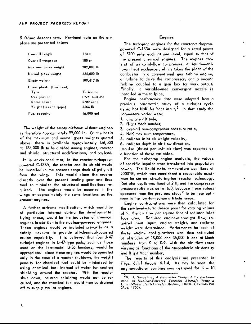
Engines
The turboprop engines for the reactor-turboprop-powered C-133A were designed for a rated powerof 5700 eshp each at sea level, equal to that ofthe present chemical engines. The engines consist of an axial-flow compressor, a liquid-metal-to-air heat exchanger, which takes the place of thecombustor in a conventional gas turbine engine,a turbine to drive the compressor, and a secondturbine coupled to a gear box for work output.Finally, a variable-area convergent nozzle isinstalled in the tailpipe.
Engine performance data were adapted from aprevious parametric study of a turbojet cycleusing hot NaK for heat input. In that study theparameters varied were:1. airplane altitude,2. flight Mach number,3. over-all ram-compressor pressure ratio,4. NaK maximum temperature,5. radiator inlet air weight velocity,6. radiator depth in air flow direction.Impulse (thrust per unit air flow) was reported asa function of these variables.
For the turboprop engine analysis, the valuesof specific impulse were translated into propulsionpower. The liquid metal temperature was fixed at2000°R, which was considered a reasonable maximum for current circulating-fuel reactor technology.Radiator depth was fixed at 2 ft, and the compressorpressure ratio was set at 6.0, because these valuesappeared from the previous study to be near optimum in the low-to-medium altitude range.
Engine configurations were then calculated forthe sea-level-static design point for varying valuesof G, the air flow per square foot of radiator inletface area. Required engine-air-weight flow, required heat input, engine weight, and radiatorweight were determined. Performance for each ofthese engine configurations was then estimatedat altitudes of 18,000 and 36,000 ft and at Machnumbers from 0 to 0.9, with the air flow ratesvarying as functions of the atmospheric air densityand flight Mach number.
The results of this analysis are presented inFigs. 6.1.1 through 6.1.4. As may be seen, theengine-radiator combinations designed for G = 10
W. H. Sandeford, A Parameter Study of the Performance of Nuclear-Powered Turbojet Aircraft Using aLiquid-Metal Heat-Transfer Medium, ORNL CF-55-8-198(Aug. 1955).
at sea-level static yield maximum power at altitude, require minimum air flow rate and minimumheat input, and yield minimum engine-radiatorweight. Therefore, G = 10 at sea-level static wastaken as the design value for the engine radiator.
In the previous study on which this analysis wasbased, an allowance of 9.6% of the engine poweroutput was made for auxiliary power requirements.
(0,000
OT 6000
2 4000
o 2000
ORNL-LR-DWG I6984A
VcS^-
MACH 0
G - AIR WEIGHT FLOW PER UNIT RADIATOR FRONTAL
AREA AT SEA LEVEL STATIC (Ib/ft2-sec)COMPRESSOR PRESSURE RATIO = 6
NaK TEMPERATURE = 2000°RRADIATOR DEPTH- 24 in.
Fig. 6.1.1. Engine Parameter Analysis of Propulsion
Power Required for Reactor-Turboprop Propulsion of a
Douglas C-133A Aircraft.
* 22 h-— <
120
80
60
O <
cc a.
w 2*^o 2a. o
20
ORNL-LR-DWG (6985A
<?*jy
»*
G - AIR WEIGHT FLOW PER UNIT RADIATOR FRONTALAREA AT SEA LEVEL STATIC (lb/ft2-sec)
COMPRESSOR PRESSURE RATI0 = 6NaK TEMPERATURE-2000°RRADIATOR DEPTH-24 in.
Fig. 6.1.2. Engine Parameter Analysis of Reactor
Power Required for Reactor-Turboprop Propulsion of a
Douglas C-133A Aircraft.
PERIOD ENDING MARCH 31, 1957
This allowance was retained in the present analy-SIS.
A preliminary engine design was calculated inorder to obtain size and weight, and details of thecomponents as tentatively envisioned are describedbelow: The compressor consists of ten axial-flowstages that give an over-all total pressure ratio of6. The tip diameter is constant at 24 in. Designspeed is 9550 rpm. Hub diameters vary from 15 in.at the inlet to 21 in. at the discharge. Work inputis constant from hub to tip and equal for the tenstages. The first stage is transonic at the rotortip. A small amount of prerotation in free vortexform is used to give an absolute circumferentialvelocity component of 75 ft/sec entering the rotortip. The use of such prerotation reduces the diffusion factor at the first-stage rotor hub and helpsto effect an even distribution of flow over the
inlet annulus. If efficiencies that vary from 0.90at the first stage to 0.88 at the tenth stage areassumed, the resulting over-all compressor efficiency is expected to be approximately 0.86.
The liquid-metal-to-air heat exchanger is of theplate-fin type. Depth in the direction of air flowis 24 in., and the frontal area perpendicular to air
120
100
UJ 80
w 40
20
ORNL-LR-DWG I6986A
. G = AIR WEIGHT FLOW PER UNIT RADIATOR FRONTAL
AREA AT SEA LEVEL STATIC (lb/ft2 sec)COMPRESSOR PRESSURE RATIO = 6
NaK TEMPERATURE = 2000°R
' RADIATOR DEPTH - 24 in.
Fig. 6.1.3. Engine Parameter Analysis of Engine-Air-
Weight Flow Required for Reactor-Turboprop Propulsion
of a Douglas C-133A Aircraft.
ANP PROJECT PROGRESS REPORT
ORNL-LR -DWGI6987A
El* GINE PLUS F(ADIATOR^
-^
'—"^ENGINE (ALL COMPONENTSEXCEPT RADIATOR)
COMPRESSOR PRESSURE RATIO = 6.0
NaK TEMPERATURE = 2000°R
2000
RADIATOR DEPTH = 24 in.
RADIATC)R (INCLUDIN G NaK)^
0
10 12 14 16 20
G,AIR WEIGHT FLOW PER UNIT RADIATOR FRONTAL AREA AT_. SEA-LEVEL STATIC (lb/ft2- sec)
Fig. 6.1.4. Engine Parameter Analysis of Engine and
Radiator Weights Required for Reactor-Turboprop Propul
sion of a Douglas C-133A Aircraft.
flow is 6.5 ft . Since for this type of engine theminimum frontal area is not a prime consideration,
the heat exchanger is in a square configuration inorder to achieve the greatest simplicity of design.Air temperature leaving the radiator is 1930°R.
As mentioned previously, the turbine section ofthe engine is separated into two parts: one turbineis used to drive the compressor and a secondprovides the outputwork. While this "free turbine"design introduces some weight and mechanicalcomplexity, it is preferred for a number of reasons.First, the power turbine can run at varying speedswith a minimum variation in compressor speed.Second, during a landing approach the compressorsection can run at maximum speed. The propellerswould be in flat pitch with their speed controlledby the back pressure exerted by a variable areanozzle on the power turbine. In the event of amissed approach, thrust could be obtained withoutwaiting for the compressor section to accelerate.
Third, windmilling of a dead engine would notcreate the drag which results when the compressoris rotated. Finally, an aircraft on the groundcould brake its propellers and allow the compressorsections to run for afterheat removal or accessorydrive. The compressor turbine has 9.6% excesscapacity to allow for extraction of accessory power,which allows a full 5700-hp output from the powerturbine. Both the compressor and the power turbineare singtofetage axial-flow types, with a constanttip diameter of 27 in.
It should be noted that this is essentially aderated engine. A turbine inlet temperature of1930°R corresponds approximately to cruise conditions on most turbine engines. The engine shouldtherefore be able to operate at full takeoff powerfor extended periods.
Consideration has been given to the possibilityof modifying an existing engine design for use withnuclear power. However, since the radiator pressure drop is higher than that of a combustion engineand the turbine inlet temperature is lower, thepropulsion power per unit air weight flow persecond (horsepower per pound of air per second)is appreciably lower in nuclear-powered enginesthan in chemically powered turbine engines. Therefore, the air-handling capacity of the nuclear-powered engine must be larger than that of theT-34 engines installed in the C-133A. No turboprop 4M»gi)nes are known which have the requiredair-handling capacity. In any event, the practicability of making such a modification is questioned.
There exists a widespread belief that a chemicalengine can be converted to run with nuclear heatsimply by replacing the combustion chamber withradiators. Unfortunately, such is not the case.The components of a turbine engine are closelycoupled both mechanically and aerodynamically.Consequently, alteration of any one component canbe expected to have a profound effect on the operation of the others. For instance, the fact that theradiator pressure loss is higher than that of atypical combustion chamber will result in a mismatch between the compressor and turbine of achemical engine. Also, the lengthening of thecompressor drive shaft to provide room for theradiators would entail the risk of problems withcritical speed. It is therefore believed that a newengine should be designed specifically for thisapplication.
It is emphasized that the required engine isnot an advanced design. The relatively low temperature level at which heat is available from theliquid metal results in low compressor-pressureratio requirements. Since the radiator will requireapproximately 6.5 ft of frontal area, there is noneed to design the compressor for high flows perunit frontal area.
The engine can therefore be simple aerodynamical ly. Such refinements as twin-spool designs orvariable-pitch stators are not needed and, indeed,are not desirable. The inlet hub-tip ratio can beconservative at 0.6 to 0.65. With the exception ofthe radiators, the design of such an engine wouldinvolve only well-established information.
In the interest of simplicity it is felt that theengine should be designed to run on nuclear heatalone rather than with chemical augmentation.The use of separate conventional chemical jetengines for an emergency power source would result in less complication of the engines and theircontrol system.
Reactor and Reactor Shield
The reactor is a reflector-moderated circulating-fuel type. Reactor and shield design data aretaken from a previous study. The reactor powerrequired for four engines was found, from Fig.6.1.2, to be about 75 Mw. The reactor core di
ameter was set at 21 in. as a compromise betweencompactness and desirable fuel properties. Byextrapolating from the ART, the weight of thereactor plus intermediate heat exchangers, pressureshell, etc., is estimated to be 14,000 lb.
Several reactor shields were designed to yielddoses of from 2.5 to 12.5 rem/hr of radiation fromthe reactor at the crew compartment, which wasassumed to be 50 ft from the reactor center. The
dose from the reactor was designed to be 10%neutrons and 90% gamma rays. Weights of reactorand shield as a function of dose at the crew shield
are plotted in Fig. 6.1.5.
Crew Shield
The dose at the crew shield was assumed to be
that due to radiation from the reactor plus 2.5rem/hr of gamma radiation from activated sodium
E. P. Blizard and H. Goldstein (eds.), Report of the1953 Summer Shielding Session, ORNL-1575 (June 14,1954).
PERIOD ENDING MARCH 31, 1957
U103)140
ORNL-LR-DWG I6988A
120
60
I I I I IDOSE: 10% NEUTRONS, 90% GAMMA RAYS
— CREW COMPARTMENT CYLINDER DIMENSIONS:
10ft LONG
3 ft DIA,
REACTOR POWER: 72 Mw
REACTOR PLUS SHIELDAND CREW SHIELD
I \I
IREACTOR PLUS SHIELD
I
|
I •CREW SHIELD
I
I4 8 12 16
DOSE 50ft FROM REACTOR CENTER (rem/hr)
20
Fig. 6.1.5. Reactor and Shield Weights as a Function
of Dose at Crew Shield of a Reactor-Powered C-133A
Aircraft.
in the NaK pipes and engine radiators. Thisfigure for sodium radiation is based upon the degreeof sodium activation anticipated in the ART. Itappears that this activation can be reduced by afactor of 5 to 10 with little weight penalty by morecareful shielding between the reactor core and theheat exchanger. Thus, the use of the 2.5 rem/4irfor sodium radiation at the crew shield introduces
a considerable degree of pessimism into theanalysis. No shielding was provided for the NaKlines and radiators, since flight shielding is moreeconomically accomplished by the crew shield.The NaK lines and radiators can be drained to
reduce radiation to tolerable levels on the ground.Considerable reduction in the activity of the
secondary fluid circuit might be realized by substituting potassium for the NaK. Both calculationsand tests indicate that the activity of the potassium should be lower than that of NaK by about a
A. M. Perry, private communication.
ANP PROJECT PROGRESS REPORT
factor ISf'iTj. Another factor of perhaps 5 could beobtained through the use of B ° in place of naturalboron for protecting the heat exchanger (at a costincrease of perhaps $100,000). Thus the totalactivity in the liquid-metal circuits could bereduced to 5 or 10 curies (and there would be someself-shielding, especially in the radiators). Thegamma rays from potassium are 1.5 Mev rather than2.5 Mev, as is the case for sodium.
The melting point of potassium is 144°F, andits specific heat is somewhat lower than that ofNaK so that the required flow rate is higher. Ifthe NaK were replaced with potassium and allother weights remained the same, the added weightwould be 3000 lb. However, if sufficient shieldingwere added to the system in which NaK was usedto give the same crew dose that would exist withpotassium, the weight with potassium would beless than the weight with NaK.
The crew compartment was assumed to be acylinder 10 ft long and 8 ft in diameter. Crewshields were designed for each value of incidentradiation encountered over the range of reactorshield weights to provide a dose inside the crewcompartment of 0.02 rem/hr. Crew shield weightswere found from a previous study and are plottedin Fig. 6.1.5.
Chemical Auxiliary Engines
The addition of two B-47-type pods (two G-EJ-47 engines each) to the nuclear C-133A airframewould provide sufficient power to cruise on chemical engines alone with the reactor shut down. TheJ-47 engines weigh approximately 2500 lb each;the installed weight for four engines is estimatedto be 14,000 lb.
The reactor shield designed for 2.5 rem/hr reactorradiation dose at the crew shield contains approximately 32,000 lb of water. If this is replaced withchemical fuel, a cruise duration of approximately1 hr on chemical power only would be provided.
E. P. Blizard and H. Goldstein (eds.). Report of the1953 Summer Shielding Session, ORNL-1575, Fig. IV-l-8,p 376 (June 14, 1954).
10
Additional chemical fuel capacity could be obtained by installing other fuel tanks at the expenseof a decrease in payload.
Weight and Payload Estimates
The -estimated weights of the components andaccessories of the nuclear powerplant, togetherwith airframe weights, are listed below (based on atotal dose of 10 rem/hr at 50 ft from the reactor).
Weight (lb)
Airframe, less engines 99,161
Engines: 4 at 4270 lb 17,080
Radiators: 4 at 1297 lb 5,188
NaK piping 3,429
Reactor (including intermediate heat 14,000
exchanger, pressure shell. fuel
pumps, etc.)
NaK pumps and drives 6,000
Reactor shield 48,000
Crew shield 27,000
Increase in structural weight 10,000
Empty weight of nuclear-powered 229,858
C-133A
Installed weight of four J-47 engines 14,000
Empty weight of C-133A aircraft plus
nuclear power plant and auxiliary
chemical engine
243,858
Based on the previously quoted values of maximum gross weight and normal gross weight for theC-133A, the available payloads are estimated asfollows:
C-133A with nuclear power
C-133A with nuclear power
and auxiliary chemical power
Maximum Normal
Payload Payload
(lb) (lb)
52,142 25,142
38,142 11,142
PERIOD ENDING MARCH 31, 7 957
6.2. TOWER SHIELDING FACILITY
C. E. Clifford
IRRADIATION OF A PRATT & WHITNEY
AIRCRAFT J-57 ENGINE
W. J. McCool1 F. J. Muckenthaler
A Pratt and Whitney Aircraft J-57 model jetengine was operated continuously for 50 hr whileit was exposed to a total tissue dose of 7 x 10⁸ergs/g from the Tower Shielding Facility (TSF)reactor in order to test the compatibility of a jetengine and a reactor system. The objectives ofthe experiment were to study the effects of radiation on the control and performance of the engine,the radiation damage to engine components, andthe induced radioactivation of the engine. Gamma-ray spectra and dose-rate measurements were takenat various positions around the engine immediatelyafter exposure and for several days followingshutdown. A description of the experiment ispresented below.
Experimental Arrangement During the Irradiation
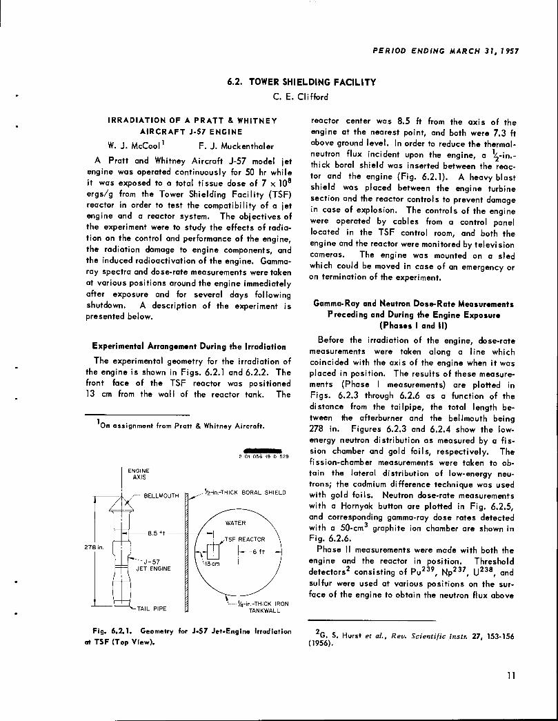
The experimental geometry for the irradiation ofthe engine is shown in Figs. 6.2.1 and 6.2.2. Thefront face of the TSF reactor was positioned13 cm from the wall of the reactor tank. The
On assignment from Pratt & Whitney Aircraft.
278 in
ENGINE
AXIS
2-01-056-I9-D-529
'/2-in.-THICK BORAL SHIELD
V'n.-THICK IRONTANKWALL
Fig. 6.2.1. Geometry for J-57 Jet-Engine Irradiation
at TSF (Top View).
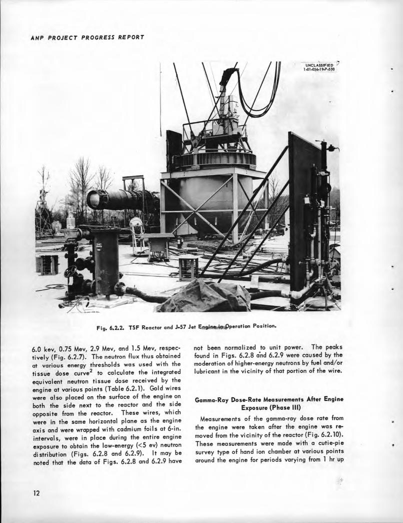
reactor center was 8.5 ft from the axis of theengine at the nearest point, and both were 7.3 ftabove ground level. In order to reduce the thermal-neutron flux incident upon the engine, a k-in.-thick boral shield was inserted between the reactor and the engine (Fig. 6.2.1). A heavy blastshield was placed between the engine turbinesection and the reactor controls to prevent damagein case of explosion. The controls of the enginewere operated by cables from a control panellocated in the TSF control room, and both theengine and the reactor were monitored by televisioncameras. The engine was mounted on a sledwhich could be moved in case of an emergency oron termination of the experiment.
Gamma-Ray and Neutron Dose-Rate MeasurementsPreceding and During the Engine Exposure
(Phases I and II)
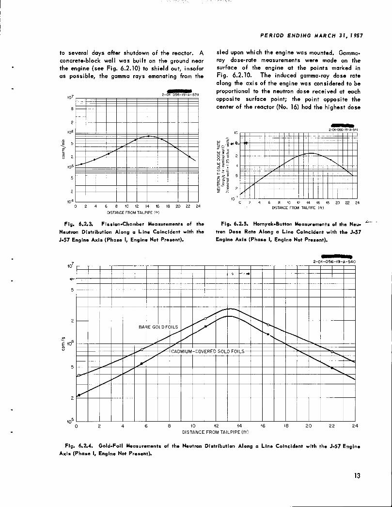
Before the irradiation of the engine, dose-ratemeasurements were taken along a line whichcoincided with the axis of the engine when it wasplaced in position. The results of these measurements (Phase I measurements) are plotted inFigs. 6.2.3 through 6.2.6 as a function of thedistance from the tailpipe, the total length between the afterburner and the bellmouth being278 in. Figures 6.2.3 and 6.2.4 show the low-energy neutron distribution as measured by a fission chamber and gold foils, respectively. Thefission-chamber measurements were taken to obtain the lateral distribution of low-energy neutrons; the cadmium difference technique was usedwith gold foils. Neutron dose-rate measurementswith a Hornyak button are plotted in Fig. 6.2.5,and corresponding gamma-ray dose rates detectedwith a 50-cm3 graphite ion chamber are shown inFig. 6.2.6.
Phase II measurements were made with both theengine and the reactor in position. Thresholddetectors2 consisting of Pu239, Np237, U238, andsulfur were used at various positions on the surface of the engine to obtain the neutron flux above
G. S. Hurst et al., Rev. Scientific Instr. 27, 153-156(1956).
11
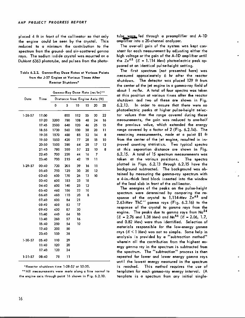
to several days after shutdown of the reactor. Aconcrete-block wall was built on the ground nearthe engine (see Fig. 6.2.10) to shield out, insofaras possible, the gamma rays emanating from the
m72-CJT-056-19- 4-539
5
2
in6
5 /
2
I05
5
2
in4
6 8 10 12 14 16
DISTANCE FROM TAILPIPE (ft)
18 20 22 24
Fig. 6.2.3. Fission-Chamber Measurements of the
Neutron Distribution Along a Line Coincident with the
J-57 Engine Axis (Phase I, Engine Not Present).
PERIOD ENDING MARCH 31, 7 957
sled upon which the engine was mounted. Gamma-ray dose-rate measurements were made on thesurface of the engine at the points marked inFig. 6.2.10. The induced gamma-ray dose ratealong the axis of the engine was considered to beproportional to the neutron dose received at eachopposite surface point; the point opposite thecenter of the reactor (No. 16) had the highest dose
.!*>*•
2-01-056-19-A-541
'*;————f: —i——-----~~~—~~
6 8 10 12 14 16 18 20 22 24
DISTANCE FROM TAILPIPE (ft)
Fig. 6.2.5. Hornyak-Button Measurements of the Neu
tron Dose Rate Along a Line Coincident with the J-57
Engine Axis (Phase I, Engine Not Present).
2-01-056-19-A-540
10
5
E (0°
10
4
BAF?E GC LDFC)ILS
*r
8 10 12 14 16
DISTANCE FROM TAILPIPE (ft)
20 22 24
Fig. 6.2.4. Gold-Foil Measurements of the Neutron Distribution Along a Line Coincident with the J-57 EngineAxis (Phase I, Engine Not Present).
13
ANP PROJECT PROGRESS REPORT
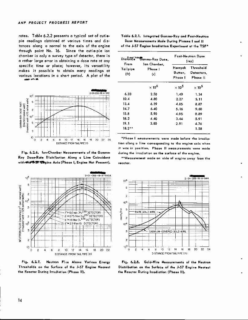
rates. Table 6.2.2 presents a typical set of cutie-pie readings obtained at various times and distances along a normal to the axis of the enginethrough point No. 16. Since the cutie-pie ionchamber is only a survey type of detector, there isa rather large error in obtaining a dose rate at anyspecific time or place; however, its versatilitymakes it possible to obtain many readings atvarious locations in a short period. A plot of the
,_, s
CC > 3=
i>2 -0 -0 56- 19-A- 542
5 V •
..-l-i
I2 •s
'" —
•v
—
-
!-
L
16 18 20 22 24
DISTANCE FROM TAILPIPE (ft)
Fig. 6.2.6. Ion-Chamber Measurements of the Gamma-
Ray Dose-Rate Distribution Along a Line Coincident
witha*he*^Sf "Myine Axis (Phase I, Engine Not Present).
icr
.i» 2
o o 10
"Co
E m
3*C —
— o
§1-J 2U. c
to
• Z. 5
10
2-01-056-I9-A-543A
"• JL
><-—- ~5»6.6 ke'v (Pu239 DETECTOR) -'» 075 Mev (Np237 DETECTOR).
^-•\---~
"*1.5Mev(U238DETECT0">?? Mbu (S DFTFr.TOR
R)
)-i—
6 8 10 12 14 16 18 20 22
DISTANCE FROM TAILPIPE (ft)
Fig. 6.2.7. Neutron Flux Above Various Energy
Thresholds on the Surface of the J-57 Engine Nearestthe Reactor During Irradiation (Phase II).
14
Table 6.2.1. Integrated Gamma-Ray and Fast-Neutron
Dose Measurements Made During Phases I and II
of the J-57 Engine Irradiation Experiment at the TSF*
p.. *.«*»•'.Distance Gamma-Ray Dose,
Fast-Neutron Dose
(rep)
Tailpipe Phase 1 Hornyak Threshold
(ft) (r)Button,
Phase 1
Detectors,
Phase II
XlO6 X 105 X 105
6.33 2.50 1.40 1.34
10.4 4.80 2.27 5.11
13.4 6.39 4.85 8.87
14.7 6.40 5.16 9.60
15.8 5.90 4.95 8.89
18.2 4.40 3.44 5.91
19.1 3.80 2.91 4.76
18.2** 1.58
*Phase I measurements were made before the irradia
tion along a line corresponding to the engine axis whenit was in position. Phase II measurements were made
during the irradiation on the surface of the engine.
**Measurement made on side of engine away from thereactor.
2
to5
10'
2-01-056-19-A-544
bAKt UULU WIKt ..
_^*
6 8 10 12 14 16 18 20 22 24
DISTANCE FROM TAILPIPE (ft)
Fig. 6.2.8. Gold-Wire Measurements of the Neutron
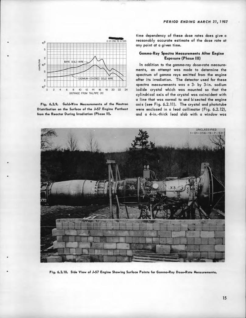
Distribution on the Surface of the J-57 Engine Nearestthe Reactor During Irradiation (Phase II).
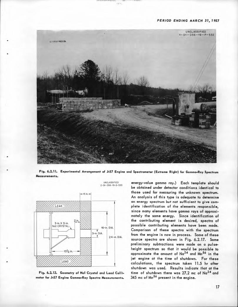
ANP PROJECT PROGRESS REPORT
placed 4 ft in front of the collimator so that onlythe engine could be seen by the crystal. Thisreduced to a minimum the contribution to the
spectrum from the ground- and air-scattered gammarays. The sodium iodide crystal was mounted on aDuMont 6363 phototube, and pulses from the photo-
Table 6.2.2. Gamma-Ray Dose Rates at Various Pbints
from the J-57 Engine at Various Times After
Reactor Shutdown*
Time
Gamma-Ray Dose 1Rate I[mr/hr) **
Date Dist.once from Engine i4.xis (ft)
0 5 10 15 20 25
1-28-57 17:00 800 112 55 30 22
17:20 3200 780 108 48 24 16
17:45 2500 640 120 46 25 15
18:55 1730 560 100 38 20 11
19:35 1570 480 85 32 14 8
19:50 1550 420 77 28 15 10
20:50 1500 380 64 28 17 12
21:45 780 300 57 22 10 8
22:40 700 220 44 16 7
23:40 700 215 42 19 11
1-29-57 00:40 720 205 39 16 11
01:40 750 120 30 20 12
02:40 600 170 26 13 10
03:40 600 185 25 18
04:40 600 140 25 12
05:40 460 100 22 10
06:40 460 110 20 8
07:40 600 84 21
08:40 405 83 17
09:40 450 87 20
11:40 440 64 10
13:40 260 57 16
15:40 250 54 10
17:40 200 50
23:40 150 38
1-30-57 05:40
11:40
17:40
110
120
120
29
20
24
1-31-57 08:40 78 11
*Reactor shutdown time 1-28-57 at 15:35.
**AII measurements were made along a line normal to
the engine axis through point 16 shown in Fig. 6.2.10.
16
tubewejjfo fed through a preamplifier and A-IDamplifier into a 20-channel analyzer.
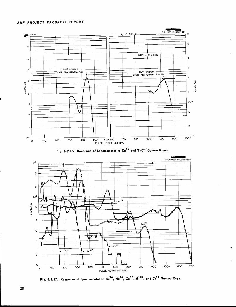
The over-all gain of the system was kept constant for each measurement by adjusting either thehigh voltage or the gain of the A-1D amplifier untilthe Zn65 (E « 1.114 Mev) photoelectric peak appeared at an identical pulse-height setting.
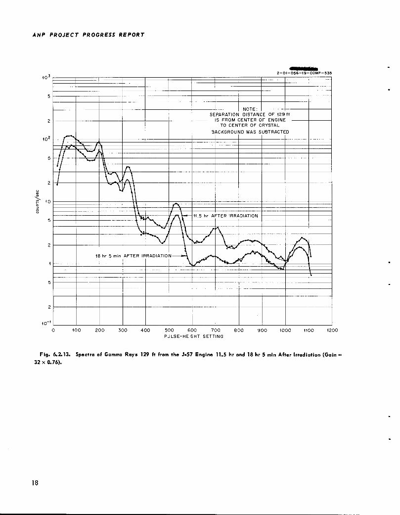
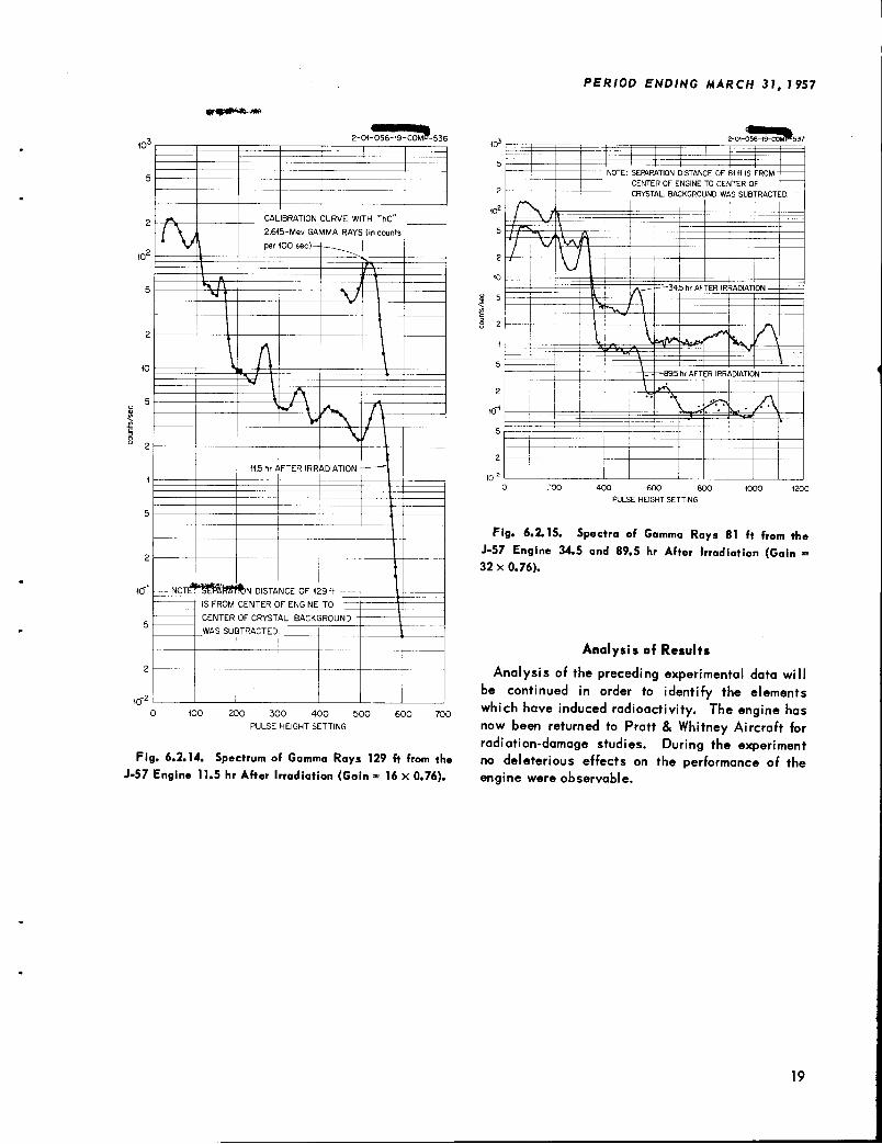
The first spectrum (not presented here) wasmeasured approximately 6 hr after the reactorshutdown. The detector was placed 129 ft fromthe center of the jet engine in a gamma-ray field ofabout 1 mr/hr. A total of four spectra was takenat this position at various times after the reactorshutdown and two of these are shown in Fig.6.2.13. In order to assure that there were no
photoelectric peaks at higher pulse-height selector values than the range covered during thesemeasurements, the gain was reduced to one-halfthe previous value, which extended the energyrange covered by a factor of 2 (Fig. 6.2.14). Theremaining measurements, made at a point 81 ftfrom the center of the jet engine, resulted in improved counting statistics. Two typical spectraat this separation distance are shown in Fig.6.2.15. A total of 15 spectrum measurements wastaken at the various positions. The spectraplotted in Figs. 6.2.13 through 6.2.15 have thebackground subtracted. The background was obtained by measuring the gamma-ray spectrum witha 4-in.-thick lead block inserted into the window
of the lead slab in front of the collimator.
The energies of the peaks on the pulse-heightspectrum were determined by comparing the response of the crystal to 1.114-Mev Zn65 and2.63-Mev ThC" gamma rays (Fig. 6.2.16) to theresponse of the crystal to gamma rays from theengine. The peaks due to gamma rays from Na(E - 2.76 and 1.38 Mev) and Mn56 (E - 2.06, 1.7,and 0.82 Mev) were thus identified. Selection ofmaterials responsible for the low-energy gammarays (E < 1 Mev) was not so simple. Some help inanalysis is provided by a "subtraction method"wherein all the contribution from the highest energy gamma ray in the spectrum is subtracted fromthe spectrum. The "subtraction" process is thenrepeated for lower and lower energy gamma raysuntil the lowest energy measured in the spectrumis reached. This method requires the use oftemplates for each gamma-ray energy interval. (Atemplate is a spectrum from any initial single-
ANP PROJECT PROGRESS REPORT
10J
10*
10
10"
2-01-056-49-COMP-535
SEPARATION OISTANCE OF 129 ft
IS FROM CENTER 0° C1II!,,IC
r~~^
TO CENTER OF C
BACKGROUND WAS S
RYSTAL
UBTRACTE D
I \1 r^ > / V//V^ ^ \ /ff \ ^—* j
II \ /
I v^<if
11.5 hr AFTER IRRADIATION
>$.
IEi hr 5 min AFTER IR RADIATIO g *\ -^t****
.-*••!**
*V ^» ^^^.
\V
100 200 300 400 500 600 700
PULSE-HEIGHT SETTING
800 900 1000 1100 1200
Fig. 6.2.13. Spectra of Gamma Rays 129 ft from the J-57 Engine 11.5 hr and 18 hr 5 min After Irradiation (Gain >
32 x 0.76).
18
snt-o**,.**
r\ CALIBRATION CURVE WITH ThC"
l\L 2.615-Mev GA
per 100 sec) —
MMA RAYS (in counts
i\\ A\r\i
/\jXAT
11.5 hr/! FTER IRR ADIATION-L i
it
Tt
IS FROM CENTER OF ENGINEt
TO i
WAS SUBTRACTED
200 300 400 500
PULSE HEIGHT SETTING
600 700
Fig. 6.2.14. Spectrum of Gamma Rays 129 ft from theJ-57 Engine 11.5 hr After Irradiation (Gain = 16 X 0.76).
•E
§ 2
PERIOD ENDING MARCH 31, 1957
.
NOTE: SEF»RATION DISTANCE OF 81 ft IS FROM-
CENTER OF ENGINE TO CENTER OF
CRYSTAL. BACKGROUND WAS SUBTRACTED.
I
-4— ~ 7=
\\/\S \
\J\ 1__ — ' {.., =-34.5 hr AFTER IRRADIATION =
1 \
h-^v-i—-=ZI 1 1_ i— | 'NK vw\—1
>*\
I
b 1= f- -}
| I
400 600 800
PULSE HEIGHT SETTING
Fig. 6.2.15. Spectra of Gamma Rays 81 ft from theJ-57 Engine 34.5 and 89.5 hr After Irradiation (Gain =32 x 0.76).
Analysis of Results
Analysis of the preceding experimental data willbe continued in order to identify the elementswhich have induced radioactivity. The engine hasnow been returned to Pratt & Whitney Aircraft forradiation-damage studies. During the experimentno deleterious effects on the performance of theengine were observable.
19
ANP PROJECT PROGRESS REPORT
m
20
*. •*• r->« §2-0I-056-19-C0MP-534
GAIN = 32 x 0.76
1— ThC" SOURCE, 12.615-Mev liAMMA RAY ~-1
.
^\S
0 100 200300 400 500 600 600 700 800 900 1000 1100 1200
PULSE HEIGHT SETTING
65
10
10'
10
Fig. 6.2.16. Response of Spectrometer to Zn and ThC Gamma Rays
2-01-056-19-C0MP-538
.__
— '
"ft—71=-Na24—
~h
1 ^-Mn
wA fA7 \-» \ V—Co58
—Cr5< \-w187
AA -A h^-Cy0 100 200 300 400 500 600 700 800 900 1000 1100 1200
PULSE HEIGHT SETTING
Fig. 6.2.17. Response of Spectrometer to Mn56, Na24, Co58, W187, and Cr5 Gamma Rays.
PERIOD ENDING MARCH 31, 1957
6.3. BULK SHIELDING FACILITY
F. C. Maienschein
PRELIMINARY MEASUREMENTS OF THE
SPECTRUM OF PROMPT GAMMA RAYS
FROM THERMAL FISSION OF U235
F. C. Maienschein R. W. PeelleT. A. Love
Prompt gamma rays, that is, those that are emittedafter fission without measurable delay, are presentin every fission reactor to the extent of about 7 Mevper fission. The spectrum and intensity of thesegamma rays must be known in order to provide asource term for any straightforward aircraft reactorshield calculation. An investigation to determinethe prompt-gamma-ray spectrum resulting fromthermal fission of U235 was initiated some timeago - it was later suspended because of thenecessity of performing other experiments - andthe data obtained in a preliminary experiment1 gavea spectrum over the small energy range covered(0.5 to 2.3 Mev) that was comparable to the resultsreported by Smith, Fields, and Friedman2 for Cf 252and by Francis and Gamble3 for U235. However,it is considered extremely important that the mostcareful and precise measurements possible becompleted in order to enable proper account to betaken of the prompt-gamma-ray source in all futurecalculations of the performance of shields suchas those for the complex reactor systems visualizedfor aircraft propulsion. Preparations, as describedbelow, are now being made for this type of experiment.
Experimental Apparatus
As described previously,1 the apparatus for theprompt-gamma-ray experiment consists of a spiralfission chamber viewed by the collimator of amultiple-crystal scintillation spectrometer. Thistype of spectrometer was chosen for its reasonablyunique response characteristics. The entireassembly in its lead and lithium shield is placedupon the top of the thermal column at the Bulk
F. C. Maienschein et al., Phys. Semiann, Prog. Rep,March 20, 1955, ORNL-1879, p 57.
2A. B. Smith, P. R. Fields, and A. M. Friedman, Phys,
Rev. 104, 699 (1956).
J. E. Francis and R. L. Gamble, Phys. Semiann.Prog. Rep. March 20, 1955. ORNL-1879, p 20.
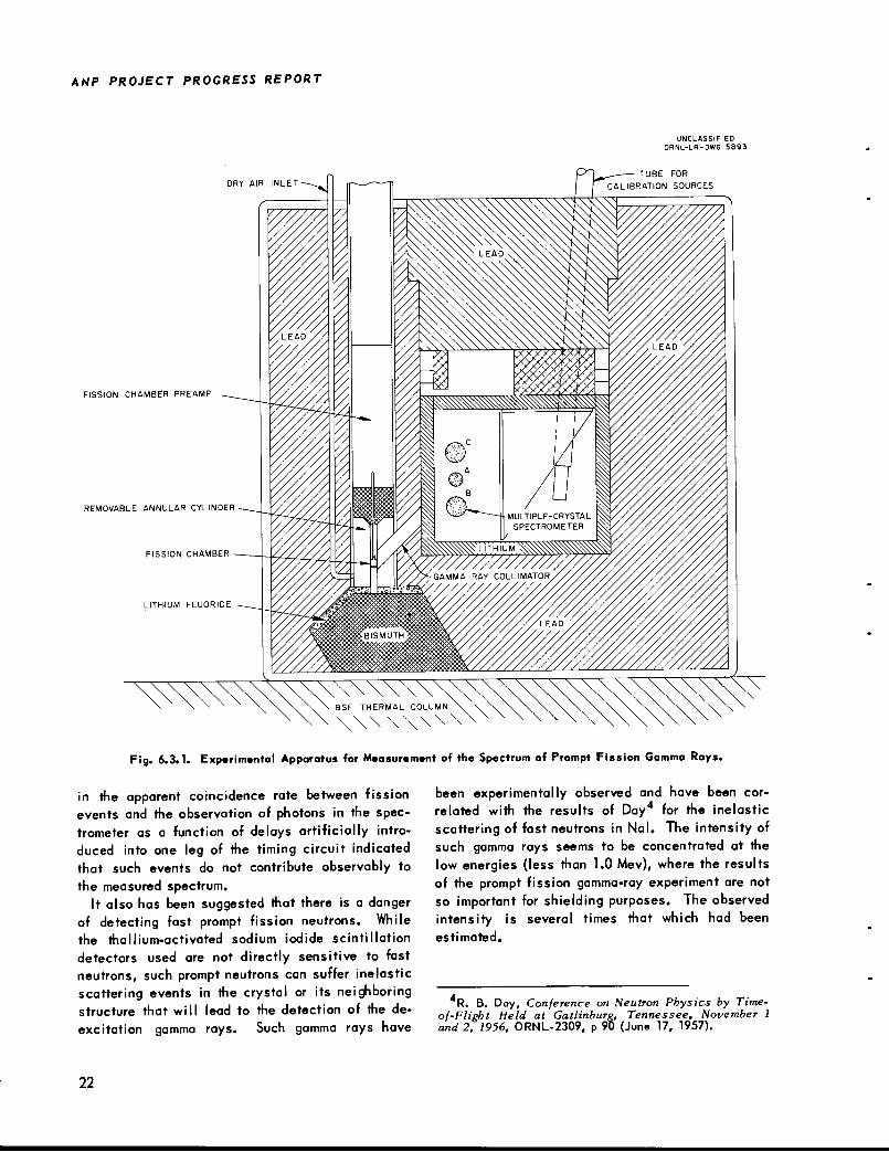
Shielding Facility (BSF), as shown in Fig. 6.3.1.Gamma rays detected in the spectrometer are recorded if they are observed in time coincidencewith an event in the fission chamber, within theexperimental time resolution. The experimentallyobserved pulse spectrum, related to the desiredgamma-ray spectrum by the instrument responsecharacteristics, is measured with the aid of amultiple-channel pulse-height analyzer. All suchelectronic equipment is largely common to otherexperiments in which the multiple-crystal spectrometer is used.
A somewhat altered experimental apparatus isnow being checked for possible experimental difficulties. One of the major changes has resultedin a narrowing of the usable time resolution from0.2 /isec, as in the previous experiments,' as wellas in another experiment,3 to about 0.06 fisec.This improvement was attained without the use of"fast" pulse amplifiers by reducing, through theuse of novel circuitry, variations in the timeinterval between a physical event in a detectorand the appearance of the corresponding timingpulse.
Another change in the pulse-height analysissystem will allow for the more rapid accumulationof data required by the experiments. This will beeffected by replacing the several 20-channel pulseanalyzers with a 128-channel analyzer (or 256-channel analyzer, if necessary). It has beennecessary to introduce a number of rather minorcircuit modifications, both to assure generallysatisfactory performance of the pulse-heightanalyzer and to adapt it to the requirements of thespecific experimental configuration. As a result,the instrument has recently been used considerablyand can now be considered to perform almost withinexpectations. Some further investigations will berequired.
Preliminary Instrument Tests
The improvement of time resolution allows fora search for delayed gamma radiation over a periodafter fission which could conceivably cause confusion in the experimental definition of prompt-gamma radiation if large numbers of delayed gammarays were emitted during the same period. However, an experimental observation of the change
21
ANP PROJECT PROGRESS REPORT
DRY AIR INLET
FISSION CHAMBER PREAMF
REMOVABLE ANNULAR CYLINDER
UNCLASSIFIEDORNL-LR-DWG 5893
TUBE FOR
CALIBRATION SOURCES
•si-
Fig. 6.3.1. Experimental Apparatus for Measurement of the Spectrum of Prompt Fission Gamma Rays.
in the apparent coincidence rate between fissionevents and the observation of photons in the spectrometer as a function of delays artificially introduced into one leg of the timing circuit indicatedthat such events do not contribute observably tothe measured spectrum.
It also has been suggested that there is a dangerof detecting fast prompt fission neutrons. Whilethe thallium-activated sodium iodide scintillationdetectors used are not directly sensitive to fastneutrons, such prompt neutrons can suffer inelasticscattering events in the crystal or its neighboringstructure that will lead to the detection of the de-excitation gamma rays. Such gamma rays have
22
been experimentally observed and have been correlated with the results of Day4 for the inelasticscattering of fast neutrons in Nal. The intensity ofsuch gamma rays seems to be concentrated at thelow energies (less than 1.0 Mev), where the resultsof the prompt fission gamma-ray experiment are notso important for shielding purposes. The observedintensity is several times that which had beenestimated.
R. B. Day, Conference on Neutron Physics by Time-of-Flight Held at Catlinbure, Tennessee, November 1and 2, 1956, ORNL-2309, p 90 (June 17, 1957).
Future Work
The equipment required for the prompt fissiongamma-ray spectrum experiment is largely in condition, except that the linearity of the pulseanalyzer must be improved. Before the experimentbegins, methods of reducing the effect of spuriousfast-neutron detection upon the observed "gamma-ray" spectrum will be investigated.
ANALYSIS OF THE FISSION-PRODUCT
GAMMA-RAY ENERGY SPECTRUM EXPERIMENT
W. Zobel
T. A. Love
R. W. Peelle
G. M. Estabrook
The data collected during the course of the experiment ' to determine the gamma-ray energyspectrum and time-dependence characteristics ofthe decay of the fission products of U are nowbeing analyzed in an attempt to obtain final corrected results. The required corrections involvemostly more careful analysis of the fission ratesin the uranium samples observed by the spectrometers and the correction of the data for the non-
uniqueness of the scintillation spectrometers.In the experiment the nonuniqueness problem
was minimized as much as possible by the use ofa multiple-crystal scintillation spectrometer whoseresponse is reasonably unique. For such instruments a large fraction of all pulses produced by asingle gamma-ray energy appear approximately atthe pulse height corresponding to that gamma-rayenergy. (In a single-crystal spectrometer thenumber of pulses observed at a given pulse heightand in a prescribed pulse-height interval generallyincludes undesired pulses corresponding to allgamma rays with energies greater than the energyof the gamma ray which it is desired to measure.)Even though the uniqueness has been maximizedin the present instrument, it is important to removefrom the results, as much as possible, the residualnonuniqueness in order that the corrected resultswill be directly interpretable. Considerable calculational efforts have been expended upon amethod designed to remove almost completely thenonuniqueness effects. A complete responsematrix was formed and inverted with the aid of the
Oracle. These efforts failed in that the final
W. Zobel and T. A. Love, Appl. Nuclear Phys. Ann.Prog. Rep. Sept. 10, 1956, ORNL-2081, p 95.
6W. Zobel and T. A. Love, ANP Quar. Prog. Rep.Sept. 10, 1956, ORNL-2157, p 291.
PERIOD ENDING MARCH 31, 1957
results appear to be meaningless, but it is notpresently clear whether the failure was due to amistake in execution or to the propagation of experimental error through the adopted calculationalprocedure. Such error propagation may have ledto errors in the corrected spectral quantities thatwere larger than the quantities themselves. Effortsare now under way to distinguish the cause of thefailure and to develop a simpler procedure ofanalysis.
AFTER-SHUTDOWN GAMMA-RAY DOSE
MEASUREMENTS
J. D. Kington
In order to check predictions of the gamma-raydose emitted from a reactor after it has been shut
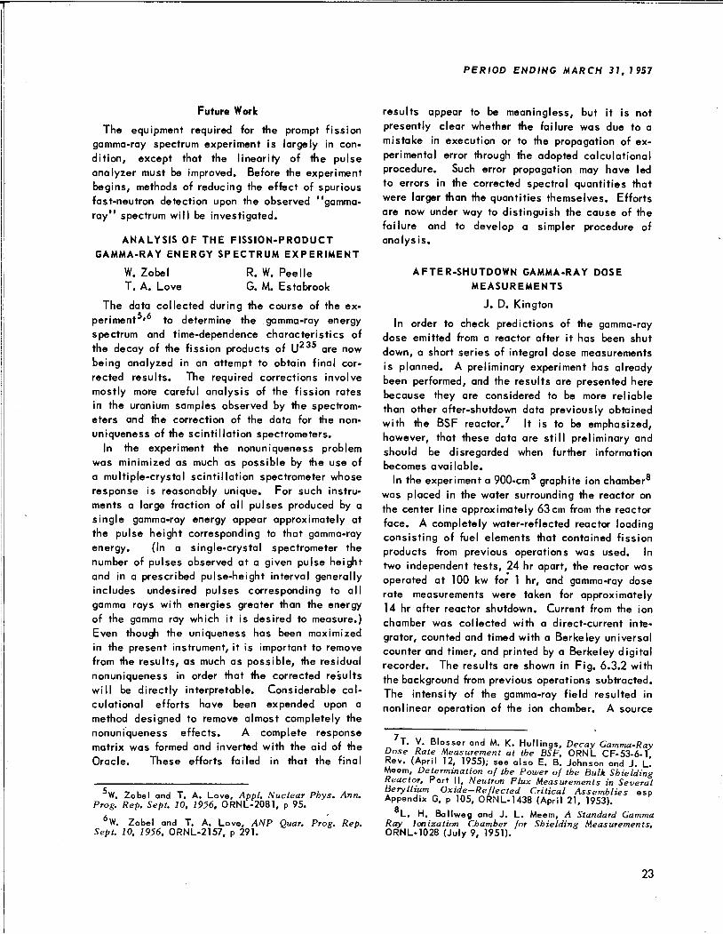
down, a short series of integral dose measurementsis planned. A preliminary experiment has alreadybeen performed, and the results are presented herebecause they are considered to be more reliablethan other after-shutdown data previously obtainedwith the BSF reactor.7 It is to be emphasized,however, that these data are still preliminary andshould be disregarded when further informationbecomes available.
In the experiment a 900-cm graphite ion chamber8was placed in the water surrounding the reactor onthe center line approximately 63cm from the reactorface. A completely water-reflected reactor loadingconsisting of fuel elements that contained fissionproducts from previous operations was used. Intwo independent tests, 24 hr apart, the reactor wasoperated at 100 kw for 1 hr, and gamma-ray doserate measurements were taken for approximately14 hr after reactor shutdown. Current from the ion
chamber was collected with a direct-current inte
grator, counted and timed with a Berkeley universalcounter and timer, and printed by a Berkeley digitalrecorder. The results are shown in Fig. 6.3.2 withthe background from previous operations subtracted.The intensity of the gamma-ray field resulted innonlinear operation of the ion chamber. A source
T. V. Blosser and M. K. Hullings, Decay Gamma-RayDose Rate Measurement at the BSF, ORNL CF-53-6-1Rev. (April 12, 1955); see also E. B. Johnson and J. l!Meem, Determination of the Power of the Bulk ShieldingReactor, Part II, Neutron Flux Measurements in SeveralBeryllium Oxide-Reflected Critical Assemblies espAppendix G, p 105, ORNL-1438 (April 21, 1953).
Q
L. H. Ballweg and J. L. Meem, A Standard GammaRay Ionization Chamber for Shielding Measurements,ORNL-1028 (July 9, 1951).
23
ANP PROJECT PROGRESS REPORT
10'12
UNCLASSIFIED
2-01-058-0-156
1 hr OF OPERATION AT 100 kw
/ NOTF5 / BACKGROUND WAS SUBTRACTED FROM BOTH CURVES.
^ SHUTDOWN;. PRELIMINARY DATA.
A
<L
1
VV1
/REACTOR
LOADING NO. 59
(WATER-REFLECTED)
m5// ^ V//////A/
\ 1 Y/,7//1 i63.1cm | 1
1 . i 1 1/
/
XSr
2
\v_- TEST 1 1 1 1/A
/// § \A
///
S^ TEST 21 %1 4,% % 900-cm3 GRAPHI TE ION CHAMBER
(0
^^/ 1 -•c
*̂«?
5/// """^^d --.
2
/ | ^^-~~—Z!T*"—•-«.
1 [>1 1
» REACTOR STARTL P "^-^~~ —~^^~"^^^
/ 1 "~~ _^"^- •/ ~- •- ,_ ^-^
/ / — •—,
-~^.^_
-,~--~^^^~
^^^Tr
I8
"^^^*>T^*\
10"
Si 10
oo
24
10
-2 -1 6 7
TIME AFTER SHUTDOWN (hr)
Fig. 6.3.2. Gamma-Ray Dose in the Water Surrounding the Bulk Shielding Reactor After Reactor Shutdown.
10 12 13 14 15
brought too near the reactor monitron caused areactor scram, which changed the rise time in thestartup of the curve for test 1.
FEASIBILITY STUDY OF A CIRCULATING-FUEL
REACTOR FOR SHIELDING TESTS
J. S. Lewin
A study was carried out to determine the feasibility of constructing a circulating-fuel reactor atthe BSF for aircraft shield tests. Since a determi
nation of the flux emerging from a typical reactorshield as a function of both energy and angle requires only a few kilowatts of reactor power, apower level <10 kw was assumed for the study. Itwas also assumed that the core volume would be
3 ft . Three fuel systems were considered. Onewas a mixture of molten fluoride salts which would
most nearly reproduce the radiation spectrum ofinterest. This fuel system would have the disadvantages of involving high temperatures and requiring a complex heat supply system to keep thefuel mixture fluid. Another fuel considered was
UF. dissolved in C-F16. The disadvantagesassociated with this system are the instability ofthe fuel under irradiation and the extreme chemical
activity of UF, gas. The system UO-SO^ dissolved in D-O appeared to be the fuel mixture whichwould be the most feasible, although the nuclearcharacteristics of a heavy-water solution are considerably different from those of the fluoride saltsproposed for the circulating-fuel reactor. Alsothere is a danger of D20, being formed in the solution. Extensive nuclear calculations would be re
quired to demonstrate the degree of nuclear approximation available from a D,0 system. Considerationwould also have to be given to the use of a D„0reflector with the addition of a neutron-capturesolute to mock up the capture gamma rays from theberyllium reflector of the circulating-fuel reactor.
PROGRAM FOR SHIELDING MEASUREMENTS
AT THE ART
G. T. Chapman
The installations which will be necessary tomake gamma-ray spectroscopic, neutron spectroscopic, and gamma-ray and neutron dose measurements at various points within the ART shield
On assignment from The Glenn L. Martin Co.
PERIOD ENDING MARCH 31, 1957
during reactor operation were described in a previous report. Recently, studies have been madeof the preoperation schedule that must be followedfor calibration and efficiency measurements of theinstruments. These measurements will be made byplacing gamma-ray sources of various knownenergies at the geometric point in space that willcoincide with the point of interest on the reactorshield and by observing the resulting sourcespectra through each of the 50-ft-long collimatortubes. In order that these measurements may bemade with confidence, the components of eachtube must be in place and the measurements mustbe made before and after the "bullnose" caps areplaced on the reactor end of the spectrometer tubes.In order to conform with the engineering testschedule on the pressure shell, this work must becompleted by December 1, 1957. Consequently, itis anticipated that the work on fabricating thespectrometer tube components will begin on July 1,1957, and the actual calibrations at the site willbe started as soon thereafter as possible.
TOTAL ABSORPTION GAMMA-RAY
SPECTROMETER
G. T. Chapman T. A. Love
It is anticipated that the detector for gamma-rayspectroscopy measurements at the ART and at theBulk Shielding Facility will consist of one large"total absorption"thallium-activated sodium iodidecrystal. Since these large crystals are not commonly in use, the characteristics of one suchcrystal are being investigated at the BSF. Thecrystal (Figs, 6.3.3 and 6.3.4) is approximately a9-in.-dia cone with one truncated end. Col lima ted
beams of gamma rays of various energies are introduced at different locations on the crystal surface,and the resulting shapes of the pulse-height spectraare observed.
Preliminary experiments have been performed to determine the collimator geometry that would have a minimum effect on the final data. The collimator finallychosen consisted of a J^-in.-dia by 10-in.-long holein a lead block. It is believed, though it has notbeen definitely proved, that this collimator reducesany exterior effects to a minimum. Some time hasalso been spent observing the effects of phototubegain misalignment, since the scintillations in the
10G. T. Chapman, ANP Quar. Prog. Rep. Dec. 31,1956, ORNL-2221, p 348-351.
25
ANP PROJECT PROGRESS REPORT
UNCLASSIFIED
2-01-058-0-162
!
o GAUSSIAN
DISTRIBUTION / \
V
•
\•
1•
I
•
•
i
1•
1•
} 1t
1
•
I 1•
1/
•o
1•
<\&
)
\•
<;
o InO ^
**.
200
180
160
140
120
100
80
60
40
20
0
-2040 50 60 70 80 90 100
RELATIVE PULSE HEIGHT
110 120
Fig
0.662-Mev Cs Gamma Rays with the Phototube Gains
Misaligned (Resolution =•= 16.1%).
6.3.5. Response of the 9-in.-dia Crystal to137
to infer enough information to arrive at reasonableshield designs, even for divided shields. However,it is felt that, for ANP shield design, detailedenergy and angular spectra for the region of thereactor shield will be required, at least for certaintest cases. For example, calculations of airscattering for a divided shield depend upon thedetails of the radiation leaving the reactor shield.The calculations are not presently adequate topredict such energy and angle spectra, and if theywere it would still be necessary to subject thecalculated results to a detailed experimental checkfor at least a few shield configurations.
Such detailed information is needed for both
gamma rays and neutrons. In order to obtain thegamma-ray spectra at the BSF it will be necessaryto position a gamma-ray spectrometer collimatorwithin 1 cm of any desired point in the pool at anangle known to within a fraction of a degree. Sincea large number of spectra will be required, it isalso important that the measuring system be simpleand reliable.
28
UNCLASSIFIED
2-0I-058-0-I63
70 80 90
RELATIVE PULSE HEIGHT
Fig. 6.3.6. Response of the 9-in.-dia Crystal to137
0.662-Mev Cs Gamma Rays with the Phototube Gains
Aligned (Resolution = 12.5%).
The BSF model IV gamma-ray spectrometer, whichconsists of a scintillation detector and an appropriate housing and collimator, will be used for themeasurements. The entire assembly, which willweigh in excess of 15 tons, must be supported bya specially designed positioner (see below). Thedesign of the shield (that is, the housing) and thecollimator arrangement is illustrated by Fig. 6.3.9.This design is based on the use of a "total absorption" sodium iodide scintillation spectrometer,which consists essentially of a 9-in.-dia rightcylinder of the scintillation material. Such aspectrometer would combine high efficiency,reasonable uniqueness of response, and simplicity
300
280
260
240
220
200
180
160
140
120
100
80
60
40
20
=>O(J
UNCLASSIFIED
2-0(-058-0-(64
'
l1.37 Mev
NOTE DASHED CURVE
SHOWS POSSIBLE COMPTON
•
SCA TTERIN G CONTRIBUT"ION.
12.76 Mev
•
A•
1•
1
i-
11 1 I
f1 RESOLUTION
16.1% — -A I
1m
I1
•
J Jii
\•
\^—l
1 S
10 20 30 40 50 60 70
RELATIVE PULSE HEIGHT
80 90
Fig. 6.3.7. Response of the 9-in.-dia Crystal to 2.76-24
and 1.37-Mev Na Gamma Rays Colli mated into theTruncated End of the Crystal.
of operation (see section above, this chapter, onTotal Absorption Gamma-Ray Spectrometer"). If
such a spectrometer does not prove to be feasible,a modified and improved form of the multiple-crystal scintillation spectrometer will be utilized.
The spectrometer collimator (Fig. 6.3.9) willconsist of two rings several inches apart.The rings will probably be constructed of high-density tungsten alloy, which will be helpful inassuring that the solid angle viewed by the unitwill not be a strong function of photon energy.These rings will be interchangeable. In order thatbackground measurements and spectrometer calibrations can be effected efficiently, the collimatorwill be intersected with a lead cylinder that willbe rotatable about an axis perpendicular to the
240
220
200
180
CO
I 160=3
>-rr
< 140H
CO
< 120
2 100cs
80
60
40
20
PERIOD ENDING MARCH 31, 1957
UNCLASSIFIED
2-01-058-0-165
i • i1
•
•
•
RESOLUTION 8.47o—-
A •
1•
1•
•
1'•W"»»
30 40 50 60 70 80 90
RELATIVE PULSE HEIGHT
100 HO
Fig. 6.3.8. Response of the 9-in.-dia Crystal to 2.76-24Mev Na Gamma Rays Collimated into the Crystal 5 in.
from the Truncated End.
collimator direction. Rotation of this lead cylinderwill provide at least three usable positions. Inone position a hole through the lead cylinder(perpendicular to the cylinder axis) will be alignedwith the holes through the tungsten rings so thata straight-through hole from the spectrometer to theedge of the shield will be effected. In anotherposition a solid lead section will plug the collimator for background measurements. A third position will place a source adjacent to the innertungsten ring for calibrations.
When a large sodium iodide crystal is used inthe vicinity of a reactor source, considerable caremust be taken to avoid background effects causedby neutron radiative captures in the materials ofthe crystal. This problem will be alleviated bymaking it more probable for the neutrons to becaptured in lithium, since such captures do notlead to radiative transitions. The lithium will beprovided in the shield, which will be cast from a
29
COo
Fig. 6.3.9. Proposed Housing and Collimator Arrangement for the BSF Model IV Gamma-Ray Spectrometer.
>RNT^T^^^^ff5!
i-
z.t>
T>70
O«-
mn
•o70
OO70
m
rn
o
ANP PROJECT PROGRESS REPORT
(f_RAIL
C_ COLUMNS
V
EL.=-19ft Oin.TO-22 ft Oin.
FROM EL. =-20 ft Oin.TO EL.+5ft Oin.
FLOOR EL. = Oft Oin.
C_ COLUMNS
Fig. 6.3.11. Proposed Design for the BSF Gamma-Ray Spectrometer Positioner.
UNCLASSIFIEDORNL-LR-DWG 21560
UNCLASSIFIED2-01-058-0-166
LUCITE SHELL
GRAPHITE SHELL-
-24 ST ALUMINUM 2 S ALUMINUM TUBE —i r-2S ALUMINUM TUBE
POLYSTYRENE-, I LUCITE—v \ GROOVE FOR O-RING--SPRING
BRASS FITTINGS
GRAPHITE COLLECTINGELECTRODE
32
GRAPHITE-7 // ^FLUOROTHENE L 2S ALUMINUM TUBE ^ POLYSTYRENE -
POLYSTYRENE-' "-MAGNESIUM
Fig. 6.3.12. A Low-Sensitivity Gamma-Ray Ion Chamber.
HIGH-VOLTAGECONNECTION
10
10
10
<<r
UJinoo
$a:
t 10°Q_
<a:cs
<C3
10
10
10°
10
UNCLASSIFIED
ORNL-LR-DWG 21561
a0t. ——
(y/
*>t^*"^
»•*"*—
!//
/ 3
900-cm3CHAMBER
0L D50-cm 3Ch AME ER
/
/
^***'
/ /
200 400 600 800 1000 1200
VOLTAGE (v)
Fig. 6.3.13. Saturation Properties of Several Gamma-
Ray Ion Chambers.
PULSED-NEUTRON METHOD FOR THE
DETERMINATION OF NEUTRON DIFFUSION
PARAMETERS IN BERYLLIUM
E. G. Silver G. deSaussure
Most reactors proposed for aircraft propulsionutilize beryllium as the reflector or moderator. Oneof the important parameters needed in order toaccurately perform calculations for such reactorsis the neutron diffusion coefficient of beryllium.An experiment is now being planned to determinethis parameter in beryllium at elevated temperatures. The experiment will apply the so-called"pulsed-neutron method," which was first described by von Dardel. The method consists of
G. F. von Dardel, "The Interaction of Neutronswith Matter^Studied with a Pulsed Neutron Source,"Kgl. Tek. HogskoL Handl. (.Trans. Roy. Inst. TechnoL,Stockholm) NR75, 185 (1954).
PERIOD ENDING MARCH 31, 1957
releasing a short burst of fast neutrons into ablock, cylinder, or sphere of the material underinvestigation and then observing the decay withtime of the thermal-neutron population. By ananalysis of this time-decay rate for several different sizes of blocks of the material, the value ofthe diffusion coefficient as a function of temperature can be determined. Less material will be
required in this method of obtaining the diffusioncoefficient than is required for the standard steady-state method. Further, at elevated temperatures,it would be difficult to position sources and detectors inside the material as required by thesteady-state method.
The temperature variation of the diffusion coefficient in beryllium at elevated temperatures isnot computable because various crystal changestake place in beryllium in this temperature rangewhich are not well understood. In order to clarifysome discrepancies between results obtained byvarious experimenters who have used this methodheretofore and in order to acquire some familiaritywith the technique, an initial experiment will beperformed with cubes of graphite. Graphite is aparticularly suitable material for study since italso is expected to exhibit marked crystal modifications.
Since the time for decay of thermal neutrons inblocks of the size to be used in this experimentis of the order of micro- or milliseconds, it isnecessary to have experimental apparatus of somecomplexity in order to measure the time behaviorof the neutrons accurately. An 18-channel variable-frequency-controlled time analyzer has been designed and built for this purpose and is in thefinal stages of testing.
The short bursts of neutrons will be producedby pulsing an ion accelerator, which will be usedwith either deuterons or tritons on a target ofdeuterium, to produce d-d or d-t neutrons. A 300-kvaccelerator has been designed and is in the process of construction. It is anticipated that theaccelerator, except for the power supply, will becompleted by June 1, 1957. However, since thepower supply will not be available before 1958,the initial phases of the experiment will be performed at the ORNL High-Voltage Laboratory(Bldg. 5500) with an accelerator available there.
33
ANP PROJECT PROGRESS REPORT
A U02-STAINLESS STEEL SHIELD TESTREACTOR FOR THE BSF
A calculation published previously demonstrated the expected hardening of the gamma-rayspectrum from a reactor core containing a stainlesssteel component as compared with that of thepresent BSF reactor containing aluminum. Theresulting higher energy spectrum would correspondmore closely to the leakage spectrum of the ART orto the spectrum of any other proposed aircraftreactor employing structural materials of the Fe-Ni-Co system. Since it is primarily the gamma-rayspectrum which varies from reactor to reactor,rather than the neutron spectrum, a reactor containing a UO,—stainless steel core would providean appreciably better source of reactor radiationsfor aircraft shielding studies than does the presentBSF reactor. It has therefore been proposed thatsuch a reactor be constructed for the BSF within
the next year. This reactor would not replace thepresent reactor, which has a uranium-aluminumcore, but would be interchangeable with it.
There are several other advantages to this newtype of core. With the proposed near-cubical design, a reactor radiation source of minimum sizewould be attained which would permit maximumflexibility in wrapping shields around the reactorcore. Further, if the planned control system,which will utilize "plate-type" control devices,is nearly as effective as preliminary results indicate, major perturbations introduced by the controldevices would be markedly reduced and the morenearly symmetrical leakage flux needed in order toaccurately analyze shield tests would be obtained.The reduced perturbation could be achieved eventhough the larger absorption cross section for theU02—stainless steel core would require moreabsorber than the present core for equal control.In addition, installation of this core will test thecorrosion resistance of the stainless steel in
reactor fuel elements. It is well known that the
aluminum cladding of the present fuel elementsis penetrated by corrosion pits within two to threeyears in process water, although the life of theelements is expected to be extended considerablyin the demineralized water now being used at theBSF. For many research reactors, the usefulportion of the fuel-element reactivity lifetime
13G. deSaussure, ANP Quar. Prog. Rep. Dec. 31, 1956,ORNL-2221, p 343.
34
could probably be extended to much longer periodswith a more durable structural material such as
stainless steel.
The mechanical features of the proposed reactorand, in particular, the control devices are described below. The criticality calculations thathave been performed to date are presented, and asummary is given of the results from a preliminaryexperiment performed to evaluate the reactivitycontrol to be achieved with the proposed plate-typecontrol devices.
Description of the Reactor
J. S. Lewin14
The basic loading of the stainless steel reactorwill consist of 25 MTR-type fuel elements in acubical 5- by 5-element lattice with a core volumeof 3300 in.3. The elements will be clad in AISItype 347 stainless steel with end plates and endboxes of the same material. Figure 6.3.14 showsthe cross section and over-all dimensions of the
fuel elements, grid plate, and control mechanism.Fuel Elements and Grid Plate. - The fuel elements
will be approximately 3 in. square in cross sectionand may be rotated ±90 deg without affecting adjacent elements. The control plates and the fourspecial fuel elements associated with them (seebelow) will maintain the same cross section. Eachfuel element will consist of 20 fuel plates, eachcontaining a fuel section 15 in. high by 2.60 in.wide by 0.020 in. thick. The stainless steelcladding over the fuel will be 0.005 in. thick. Endboxes of the fuel elements will be minimized in
size to reduce the amount of parasitic capture nearthe core.
The material selected for the grid plate is theprecipitation-hardening stainless steel 17-7 PH.Since this steel can be hardened to an Rc of 40,a grid plate design which will permit reduction ofthe grid plate thickness to 0.85 in. will be used.The grid plate will be ground to a surface flat towithin 0.006 in. The fuel-element end boxes will
have ground pedestal surfaces that will rest on thegrid plate and 2^-in.-dia shanks that will be usedonly for positioning the fuel elements in thelattice. Three strips pressed into and projectingabove the surface of the grid plate will preventrotation of the fuel elements about the vertical
14On assignment from The Glenn L. Martin Co.
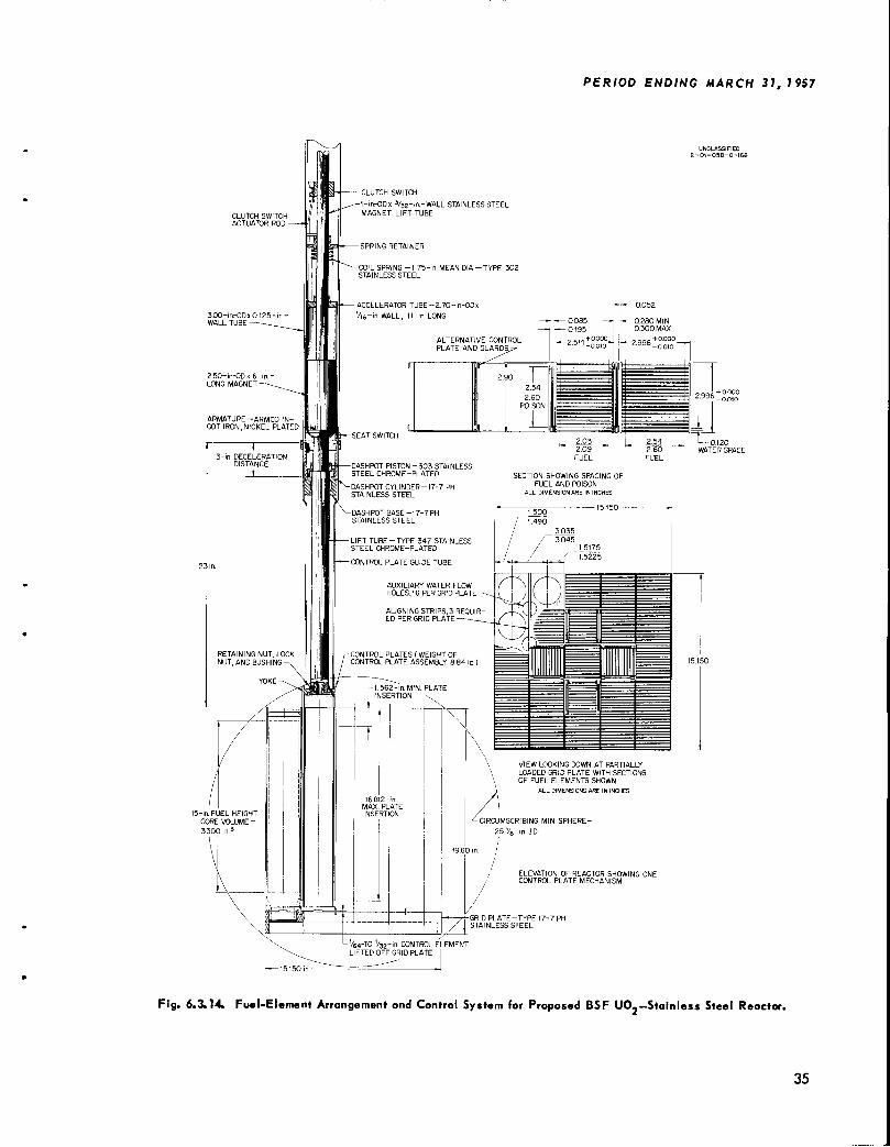
CLUTCH SWITCHACTUATOR ROD
3.00-in-OD* 0.125WALL TUBE
15-in FUEL HEIGHT
CORE VOLUME =
3300 in3
-CLUTCH SWITCH
-inrODx 3/32-in.-WALL STAINLESS STEELMAGNET LIFT TUBE
PERIOD ENDING MARCH 31, 1957
ELEVATION OF REACTOR SHOWING ONECONTROL PLATE MECHANISM
-GRID PLATE-TYPE 17-7 PH, STAINLESS STEEL
Fig. 6.3.14. Fuel-Element Arrangement and Control System for Proposed BSF UO.-Stainless Steel Reactor.
35
ANP PROJECT PROGRESS REPORT
axis. The grid plate will be stiffened by a 1-in.-thick frame to limit the deflection slope to amaximum of 0.00023 in./in.
Four fuel elements will be modified to receive
the control plates, the widths being decreased to2.514 in. across the end plates. This is equivalentto a loss of 3.7 fusl plates distributed equallybetween two sides of the fuel element, or 18.5% ofthe fuel. The resultant water gap that will existbetween the modified fuel element and an adjacentfuel element when a control plate is withdrawnwill be 0.280 to 0.300 in. The upper ends of themodified fuel element will be fitted with stainlesssteel adapters that will join the fuel element tothe control-plate guide tube.
Control Plates. - The control plates and theirlifting mechanism are shown in Fig. 6.3.14. Theplates will be rolled sandwiches of type 347 stainless steel faces around a core of boron dispersedin iron; each plate will contain the equivalent ofabout 4.5 g of B10. The control plates will bepaired, so that four lifting mechanisms will berequired for eight plates. The drive motor will bethe coaxial drive unit now used on the aluminum-
clad core of the BSF reactor, but it will be equippedwith a thrust bearing for push as well as liftcapability.
In a reactor scram, each control plate assemblywill receive an initial downward acceleration of
about 8 g which will decrease to about /2 g in4k in. This acceleration will be supplied by acoil spring and accelerator tube. Thus the drivemotor will have to exert a thrust sufficient to fullycompress the accelerator spring and allow themagnet to engage the armature. During this compression stroke the 20-ft-long magnet lift tubewill be subjected to buckling stresses, and therefore it will be constructed of a l-in.-OD stainless
steel tube with Tij-in.-thick walls. Once themagnet has engaged the armature, the stress in themagnet lift tube will become tensile and localizedbetween the magnet and the spring retainer fitting9/2 in. above the magnet. The total weight of thecontrol plate assembly will be 8.8 lb, and theweight of the spring and accelerator tube will be2.7 lb. The total force supported by the magnet,including the 82-lb spring compression force, thuswill be 93.5 lb. The buckling stress margin ofsafety will be +70% since a 20-ft-long tube willbuckle at 138 lb. Should additional strength berequired, the tube can be redesigned easily.
36
Calculations of the plate drop time from the fullywithdrawn position were made for an initial acceleration of 6.5 g, assuming a dynamic water dragcoefficient of 1.4 on 2/2 projected areas of 2.65in.each. (The effects of the distances between thepiston, the control plates, and the armature andtheir respective areas were estimated to be equivalent to 2/2 projected areas.) The results indicatethat the net time to drop 12 in. will be 0.141 sec.This does not include magnet release time. Amagnet for this reactor is being developed that isto exert a minimum 100-lb force on the armature,and the release time may be as low as 10 msec. Areduction in drop time of 50% over that of thepresent gravity-accelerated rods appears to bepossible.
After the initial 12 in. of drop, deceleration willbegin in a hydraulic dashpot in which water will besqueezed out around the piston and piston rod. Calculations of the motion during deceleration were madein which the shape of the dashpot body was variedand various coefficients of discharge through thetwo orifices were assumed. The dashpot body wasdesigned as a compromise between ease of machining and the attainment of the least shock, asindicated by the calculations. The force of deceleration will be absorbed as tension in the
magnet guide tube, since the control elementassembly will be shimmed at the drive motor sothat it will be supported at the top and will notrest on the grid plate.
Possible binding of the control plates was investigated. The space allowed for the controlplates was established on the basis of fabricationtolerances and thermal expansion. If all fabrication tolerances were cumulatively consumed in theunfavorable direction, the remaining space betweencontrol plate and adjacent fuel element would notbe closed up until the temperature of the metalrose to 830°F. An alternative control plate design,also shown in Fig. 6.3.14, is under consideration.In this design, channel section guards have beenadded at the ends of the control plate and thestiffener strips have been relocated from the endsof the control plate to the center.
It is recognized that with the first arrangement,wear of rubbing surfaces may, in time, increasethe possible shifting of the relative position of thecontrol plates and the fuel elements. An investigation of apparent coefficients of friction underwater has been started. Initial results show that
smoothly finished surfaces are undesirable undereven light unit pressure, since they tend to squeezeout the water between them and create a vacuum.One striated surface rubbing against a smoothsurface tends to maintain a lubricating water filmwhich exhibits an apparent coefficient of frictionof 0.02 to 0.03, regardless of the materials involved.
A full-size test assembly of the control plateconfiguration has been fabricated and will betested in the near future. The tests will providedata on the magnet, the motion of the control plates,distortion tendencies, and wear. Unfavorable conditions of distortion and forces will be imposed onthe control plates and adjacent elements. Thedecision on adopting the alternative control platewill be based on results of this test.
Heat Transfer Calculations
J. S. Lewin
Preliminary heat transfer calculations were madeby a method of successive approximations of theaverage water density in the central fuel element,as follows:
(1) dQz = qzA dz (Btu/hr) ,
(2) Qz = xCp(Tz - TQ) (Btu/hr) ,
(3) x = Awvj>z (Ib/hr) ,
(4) vz = 3600 (in./hr) ,
where
Q = total heat transferred to water in length zof fuel elements, Btu/hr,
qz = heat generation rate at any point z incentral fuel element, Btu/hr-in. ,
x = mass water flow (Ib/hr),
z = dimension along length of fuel element, in.,
Tz = mean water temperature at point z, °F,
TQ = water temperature in pool, °F,
v = average velocity of water flow over area Aat point z, in./hr,
A = gross cross section of fuel element, in.2,
A = cross section available for water flow,w 2
in. ,
PERIOD ENDING MARCH 31, 1957
p = water density at point z, corresponding totemperature Tz, lb/in.3,
p = average water density in length z, lb/in. ,
p0 = density of surrounding pool water, lb/in. ,g = acceleration of gravity, in./sec ,
C = heat capacity, Btu/lb«°F.
A simple cosine distribution of flux was assumed,with a peak-to-average flux ratio of 2.6. Based onthis assumption
2.60 P /ttz\ .
(5) «« -W Si" (l5) (B'̂ "-8> 'where P is the reactor thermal power level, Btu/hr.
The method used was to find Q by use of Eqs. 1and 5. Then, x was plotted as a function of(Tz —TQ). A value for (Tz —Tn) was then assumed and p was obtained from a curve of p vs T,
' z r
By using this pz, vz was found from Eq. 4, afterwhich x was found from Eq. 3. This x, substitutedback into Eq. 2 should yield the originally assumed(T - rn). If it did not, a new {Tz - TQ) wasassumed and the process was repeated untilassumed and resultant temperature' differenceschecked.
The temperature of the fuel plate surface wasthen found from
(6)Qz -
+ Trha z
where
T' = fuel plate wall temperature at point z, °F,
h = average heat transfer coefficient overlength z, Btu/hr.°F.ft2,
a = surface area available for heat transfer in
length z, ft2,
T = average fluid temperature over length z,°F.
With 20 fuel plates per element, the plate surfacetemperature, T , in the central fuel element wasfound to reach 239°F, the boiling point for waterunder a head of 20 ft, at a reactor power of about700 kw. The effective heat transfer coefficient h
was 140 Btu/hr«°F»ft2. At this same power level,the average water temperature rise in passingthrough the fuel element was 62°F. Thus thestainless steel reactor would be limited in powerlevel to a few hundred kilowatts. Based on past
37
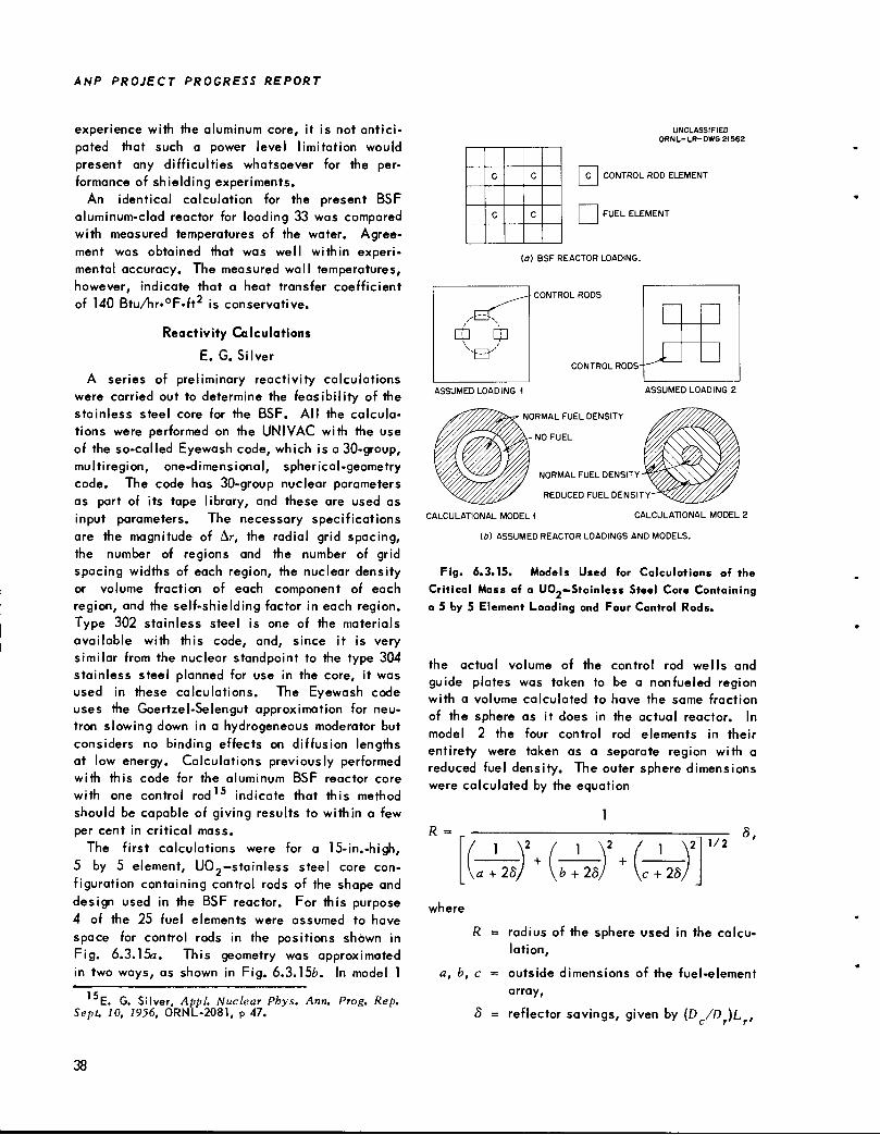
ANP PROJECT PROGRESS REPORT
experience with the aluminum core, it is not anticipated that such a power level limitation wouldpresent any difficulties whatsoever for the performance of shielding experiments.
An identical calculation for the present BSFaluminum-clad reactor for loading 33 was comparedwith measured temperatures of the water. Agreement was obtained that was well within experimental accuracy. The measured wall temperatures,however, indicate that a heat transfer coefficientof 140 Btu/hr«°F«ft is conservative.
Reactivity Calculations
E. G. Silver
A series of preliminary reactivity calculationswere carried out to determine the feasibility of thestainless steel core for the BSF. All the calcula
tions were performed on the UNIVAC with the useof the so-called Eyewash code, which is a 30-group,multiregion, one-dimensional, spherical-geometrycode. The code has 30-group nuclear parametersas part of its tape library, and these are used asinput parameters. The necessary specificationsare the magnitude of Ar, the radial grid spacing,the number of regions and the number of gridspacing widths of each region, the nuclear densityor volume fraction of each component of eachregion, and the self-shielding factor in each region.Type 302 stainless steel is one of the materialsavailable with this code, and, since it is verysimilar from the nuclear standpoint to the type 304stainless steel planned for use in the core, it wasused in these calculations. The Eyewash codeuses the Goertzel-Selengut approximation for neutron slowing down in a hydrogeneous moderator butconsiders no binding effects on diffusion lengthsat low energy. Calculations previously performedwith this code for the aluminum BSF reactor core
with one control rod indicate that this method
should be capable of giving results to within a fewper cent in critical mass.
The first calculations were for a 15-in.-high,5 by 5 element, U02-stainless steel core configuration containing control rods of the shape anddesign used in the BSF reactor. For this purpose4 of the 25 fuel elements were assumed to have
space for control rods in the positions shown inFig. 6.3.15a. This geometry was approximatedin two ways, as shown in Fig. 6.3.156. In model 1
E. G. Silver, Appl. Nuclear Phys. Ann. Prog. Rep.Sept. 10, 1956, ORNL-2081, p 47.
38
UNCLASSIFIED
ORNL-LR-DWS 21562
C C
C C
IC ICONTROL ROD ELEMENT
I |FUEL ELEMENT
(o) BSF REACTOR LOADING.
CONTROL RODS
CONTROL RODS
NORMAL FUEL DENSITY
NO FUEL
NORMAL FUEL DENSITY -
REDUCED FUEL DENSITY'
CALCULATIONAL MODEL 1 CALCULATIONAL MODEL 2
(*) ASSUMED REACTOR LOADINGS AND MODELS.
Fig. 6.3.15. Models Used for Calculations of the
Critical Mass of a UOj-Stainless Steel Core Containinga 5 by 5 Element Loading and Four Control Rods.
the actual volume of the control rod wells and
guide plates was taken to be a nonfueled regionwith a volume calculated to have the same fraction
of the sphere as it does in the actual reactor. Inmodel 2 the four control rod elements in their
entirety were taken as a separate region with areduced fuel density. The outer sphere dimensionswere calculated by the equation
1R =
1 11/2
8,
+ 2S, b + 28 c + 25
vhere
R =
a, b, c
8
radius of the sphere used in the calculation,
outside dimensions of the fuel-element
array,
reflector savings, given by (D /D )L ,
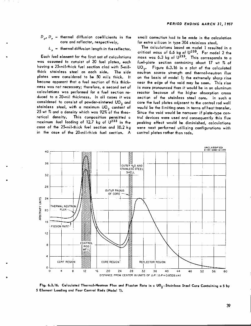
Dc, Df = thermal diffusion coefficients in thecore and reflector, respectively,
Lf = thermal diffusion length in the reflector.
Each fuel element for the first set of calculationswas assumed to consist of 20 fuel plates, eachhaving a 25-mil-thick fuel section clad with 5-mil-thick stainless steel on each side. The sideplates were considered to be 50 mils thick. Itbecame apparent that a fuel section of this thickness was not necessary; therefore, a second set ofcalculations was performed for a fuel section reduced to a 20-mil thickness. In all cases it was
considered to consist of powder-sintered U0- andstainless steel, with a maximum UO, content of25 wt % and a density which was 92% of the theoretical density. This composition permitted amaximum fuel loading of 12.7 kg of U235 in thecase of the 25-mil-thick fuel section and 10.2 kgin the case of the 20-mil-thick fuel section. A
< 20
PERIOD ENDING MARCH 31, 1957
small correction had to be made in the calculationfor extra silicon in type 304 stainless steel.
The calculations based on model 1 resulted in acritical mass of 6.6 kg of U235. For model 2 themass was 6.3 kg of U235. This corresponds to afuel-plate section containing about 17 wt % ofU02. Figure 6.3.16 is a plot of the calculatedneutron source strength and thermal-neutron fluxon the basis of model 1; the extremely sharp risenear the edge of the void may be seen. This riseis more pronounced than it would be in an aluminumreactor because of the higher absorption crosssection of the stainless steel core. In such a
core the fuel plates adjacent to the control rod wellwould be the limiting ones in terms of heat transfer.Since the void would be narrower if plate-type control devices were used and consequently this fluxpeaking effect would be diminished, calculationswere next performed utilizing configurations withcontrol plates rather than rods.
UNCLASSIFIED2-01-058-0-170
16 20 24 28 32 36 40 44
DISTANCE FROM CENTER IN UNITS OF Aff (A/? = 0.8526 cm)
Fig. 6.3.16. Calculated Thermal-Neutron Flux and Fission Rate in a UO.-Stainless Steel Core Containing a 5 by5 Element Loading and Four Control Rods (Model 1).
39
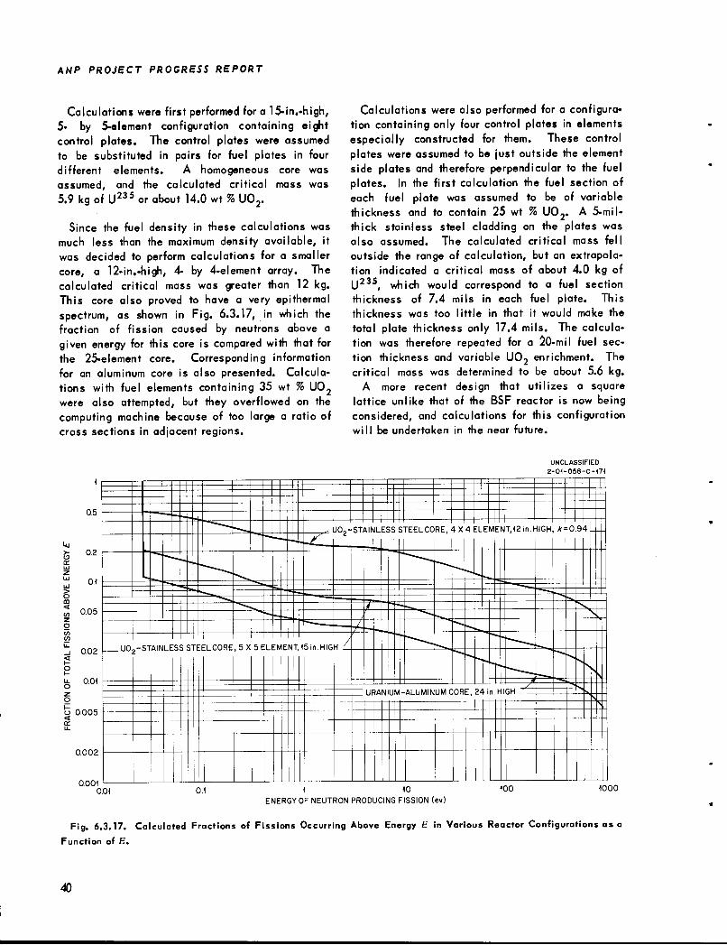
ANP PROJECT PROGRESS REPORT
Calculations were first performed for a 15-in.-high,5- by 5-element configuration containing eightcontrol plates. The control plates were assumedto be substituted in pairs for fuel plates in fourdifferent elements. A homogeneous core wasassumed, and the calculated critical mass was5.9 kg of U23S or about 14.0 wt %U02.
Since the fuel density in these calculations wasmuch less than the maximum density available, itwas decided to perform calculations for a smallercore, a 12-in.-high, 4- by 4-element array. Thecalculated critical mass was greater than 12 kg.This core also proved to have a very epithermalspectrum, as shown in Fig. 6.3.17, in which thefraction of fission caused by neutrons above agiven energy for this core is compared with that forthe 25-element core. Corresponding informationfor an aluminum core is also presented. Calculations with fuel elements containing 35 wt % U02were also attempted, but they overflowed on thecomputing machine because of too large a ratio ofcross sections in adjacent regions.
Calculations were also performed for a configuration containing only four control plates in elementsespecially constructed for them. These controlplates were assumed to be just outside the elementside plates and therefore perpendicular to the fuelplates. In the first calculation the fuel section ofeach fuel plate was assumed to be of variablethickness and to contain 25 wt % U02. A 5-mil-thick stainless steel cladding on the plates wasalso assumed. The calculated critical mass felloutside the range of calculation, but an extrapolation indicated a critical mass of about 4.0 kg ofU235, which would correspond to a fuel sectionthickness of 7.4 mils in each fuel plate. Thisthickness was too little in that it would make the
total plate thickness only 17.4 mils. The calculation was therefore repeated for a 20-mil fuel section thickness and variable U02 enrichment. Thecritical mass was determined to be about 5.6 kg.
A more recent design that utilizes a squarelattice unlike that of the BSF reactor is now beingconsidered, and calculations for this configurationwill be undertaken in the near future.
IT
s<
o
CO
o
o
zo
0.5
0.2
0.1
0.05
0.02
0.01
o 0.005<
0.002
UNCLASSIFIED
2-01-058-0-171
.-• J02-STAINLESS> STEEL CO RE, *X 4 ELEM ENT,12in.HIGH, * = 0.94
..^j
—=-^
uo rSTAIN LE SSS TEELC0RE ,5X 5E L EMENT,15in.HIGA
^ '**
URANIL M-ALUMINUM CORE, 24 in HIGH '
0.0010.01 0.1 1 10
ENERGY OF NEUTRON PRODUCING FISSION (ev)
100 1000
Fig. 6.3.17. Calculated Fractions of Fissions Occurring Above Energy E in Various Reactor Configurations as aFunction of E.
40
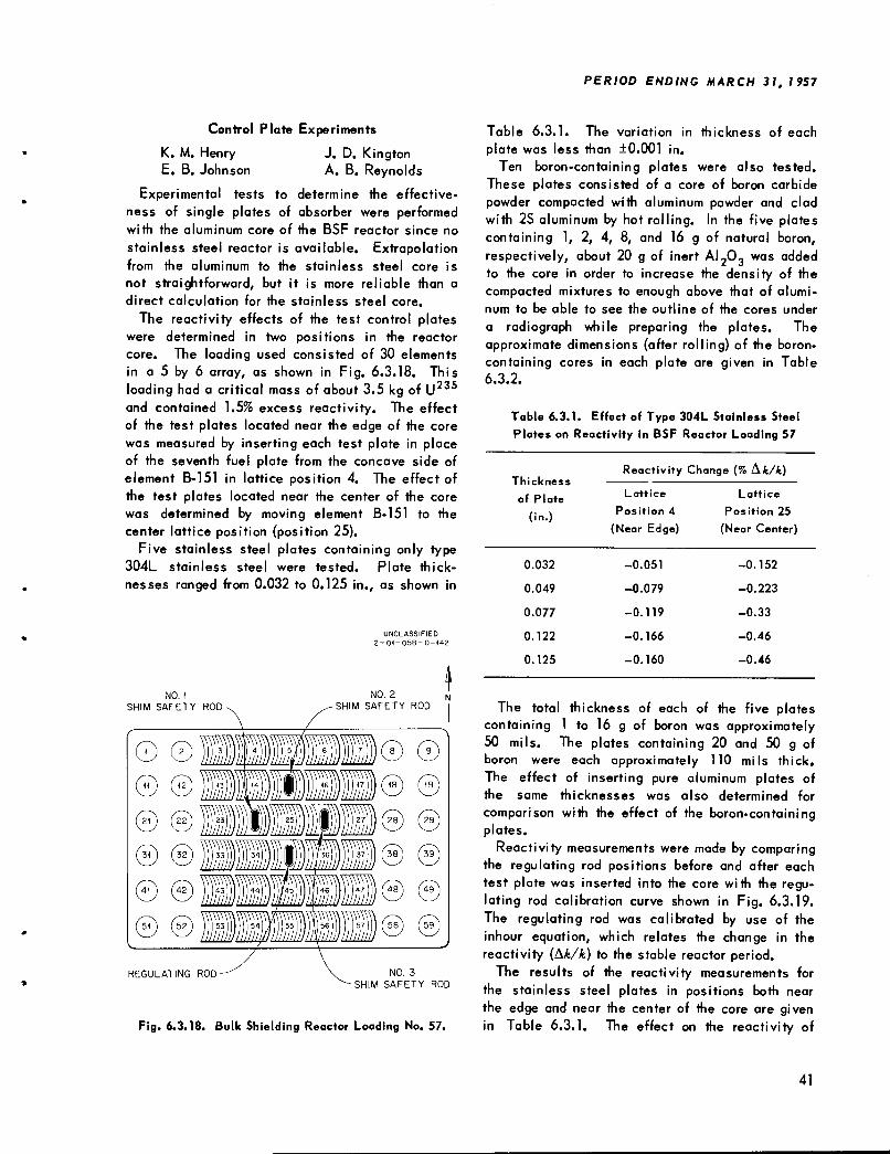
Control Plate Experiments
K. M. Henry J. D. KingtonE. B. Johnson A. B. Reynolds
Experimental tests to determine the effectiveness of single plates of absorber were performedwith the aluminum core of the BSF reactor since no
stainless steel reactor is available. Extrapolationfrom the aluminum to the stainless steel core isnot straightforward, but it is more reliable than adirect calculation for the stainless steel core.
The reactivity effects of the test control plateswere determined in two positions in the reactorcore. The loading used consisted of 30 elementsin a 5 by 6 array, as shown in Fig. 6.3.18. Thisloading had a critical mass of about 3.5 kg of U235and contained 1.5% excess reactivity. The effectof the test plates located near the edge of the corewas measured by inserting each test plate in placeof the seventh fuel plate from the concave side ofelement B-151 in lattice position 4. The effect ofthe test plates located near the center of the corewas determined by moving element B-151 to thecenter lattice position (position 25).
Five stainless steel plates containing only type304L stainless steel were tested. Plate thicknesses ranged from 0.032 to 0.125 in., as shown in
NO. 1
SHIM SAFETY ROD
0 ©© ©
© ©
© ©© ©
©
REGULATING ROD
UNCLASSIFIED
2-01-058-0-142
NO. 3
SHIM SAFETY ROD
Fig. 6.3.18. Bulk Shielding Reactor Loading No. 57.
PERIOD ENDING MARCH 31, 1957
Table 6.3.1. The variation in thickness of each
plate was less than ±0.001 in.Ten boron-containing plates were also tested.
These plates consisted of a core of boron carbidepowder compacted with aluminum powder and cladwith 2S aluminum by hot rolling. In the five platescontaining 1, 2, 4, 8, and 16 g of natural boron,respectively, about 20 g of inert ALO, was addedto the core in order to increase the density of thecompacted mixtures to enough above that of aluminum to be able to see the outline of the cores under
a radiograph while preparing the plates. Theapproximate dimensions (after rolling) of the boron-containing cores in each plate are given in Table6.3.2.
Table 6.3.1. Effect of Type 304L Stainless Steel
Plates on Reactivity in BSF Reactor Loading 57
Thickness
of Plate
(in.)
Reactivity Change (% &k/k)
Lattice
Position 4
Lattice
Position 25
(Near Edge) (Near Center)
0.032 -0.051 -0.152
0.049 -0.079 -0.223
0.077 -0.119 -0.33
0.122 -0.166 -0.46
0.125 -0.160 -0.46
The total thickness of each of the five platescontaining 1 to 16 g of boron was approximately50 mils. The plates containing 20 and 50 g ofboron were each approximately 110 mils thick.The effect of inserting pure aluminum plates ofthe same thicknesses was also determined forcomparison with the effect of the boron-containingplates.
Reactivity measurements were made by comparingthe regulating rod positions before and after eachtest plate was inserted into the core with the regulating rod calibration curve shown in Fig. 6.3.19.The regulating rod was calibrated by use of theinhour equation, which relates the change in thereactivity (Ak/k) to the stable reactor period.
The results of the reactivity measurements forthe stainless steel plates in positions both nearthe edge and near the center of the core are givenin Table 6.3.1. The effect on the reactivity of
41
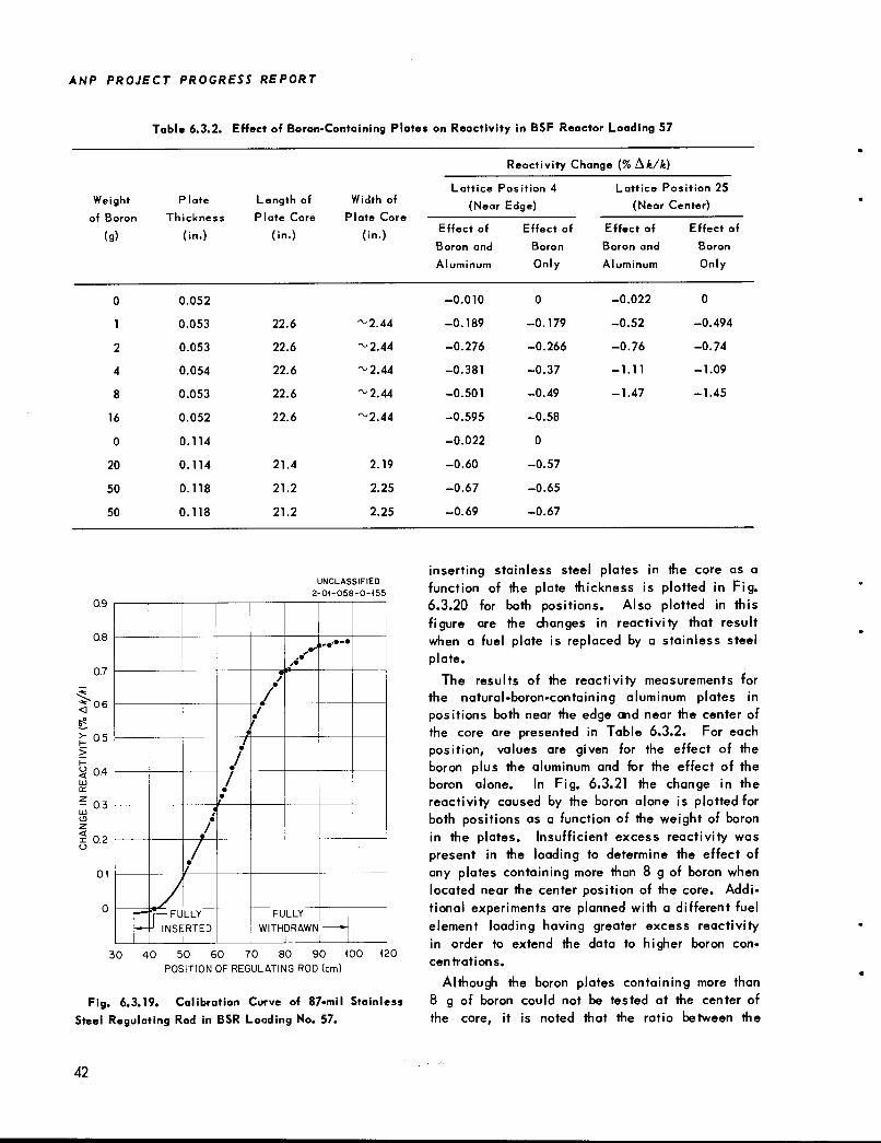
ANP PROJECT PROGRESS REPORT
Table 6.3.2. Effect of Boron-Containing Plates on Reactivity in BSF Reactor Loading 57
Plate
Thickness
(in.)
L
PI
ength of
ate Core
(in.)
Width of
Plate Core
(in.)
Reactivity Che nge (%Ak/k)
Weight
of Boron
(9)
Lattice Position 4
(Near Edge)
Lattice Position 25
(Near Center)
Effect of
Boron and
Effect of
Boron
Effect of
Boron and
Effect of
Boron
Aluminum Only Aluminum Only
0 0.052 -0.010 0 -0.022 0
1 0.053 22.6 ~2.44 -0.189 -0.179 -0.52 -0.494
2 0.053 22.6 -^2.44 -0.276 -0.266 -0.76 -0.74
4 0.054 22.6 ~2.44 -0.381 -0.37 -1.11 -1.09
8 0.053 22.6 ~2.44 -0.501 -0.49 -1.47 -1.45
16 0.052 22.6 ~2.44 -0.595 -0.58
0 0.114 -0.022 0
20 0.114 21.4 2.19 -0.60 -0.57
50 0.118 21.2 2.25 -0.67 -0.65
50 0.118 21.2 2.25 -0.69 -0.67
0.9
0.8
07
3 °6
£ 0.5>
§ 04UJcc
^0.3IdCDZ
x 0.2o
0.1
UNCLASSIFIED
2-01-058-0-155
>•
,-••-•
ja
i1
•
/•
•
f<
1
r*
1./-r— FULLY
J INSERTED1
FULLY
WITHDRAWN
1
30 40 50 60 70 80 90 100
POSITION OF REGULATING ROD (cm)
120
Fig. 6.3.19. Calibration Curve of 87-mil Stainless
Steel Regulating Rod in BSR Loading No. 57.
42
inserting stainless steel plates in the core as afunction of the plate thickness is plotted in Fig.6.3.20 for both positions. Also plotted in thisfigure are the changes in reactivity that resultwhen a fuel plate is replaced by a stainless steelplate.
The results of the reactivity measurements forthe natural-boron-containing aluminum plates inpositions both near the edge and near the center ofthe core are presented in Table 6.3.2. For eachposition, values are given for the effect of theboron plus the aluminum and for the effect of theboron alone. In Fig. 6.3.21 the change in thereactivity caused by the boron alone is plotted forboth positions as a function of the weight of boronin the plates. Insufficient excess reactivity waspresent in the loading to determine the effect ofany plates containing more than 8 g of boron whenlocated near the center position of the core. Additional experiments are planned with a different fuelelement loading having greater excess reactivityin order to extend the data to higher boron concentrations.
Although the boron plates containing more than8 g of boron could not be tested at the center ofthe core, it is noted that the ratio between the
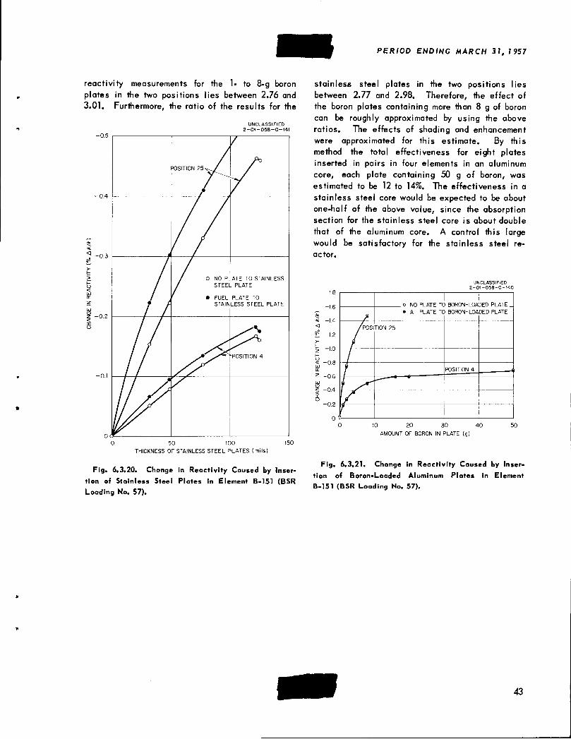
reactivity measurements for the 1- to 8-g boronplates in the two positions lies between 2.76 and3.01. Furthermore, the ratio of the results for the
UNCLASSIFIED
2-01-058-0-14
=0SITI0N 25^
•
-0.4
^
1 0.3/
>-r-
> / / ° NO PL ATE TO STAINLESS
<UJ / STEEL PLATE
/ ,' e FUEL PLATE TOz STAINLESS STEEL PLATEUJ
2 0.2<Xo ^\
M POSITION 4
-0.1
od
iA/
0 50 100 150
THICKNESS OF STAINLESS STEEL PLATES (mils)
Fig. 6.3.20. Change in Reactivity Caused by Inser
tion of Stainless Steel Plates in Element B-151 (BSR
Loading No. 57).
PERIOD ENDING MARCH 31, 1957
stainless steel plates in the two positions liesbetween 2.77 and 2.98. Therefore, the effect ofthe boron plates containing more than 8 g of boroncan be roughly approximated by using the aboveratios. The effects of shading and enhancementwere approximated for this estimate. By thismethod the total effectiveness for eight platesinserted in pairs in four elements in an aluminumcore, each plate containing 50 g of boron, wasestimated to be 12 to 14%. The effectiveness in a
stainless steel core would be expected to be aboutone-half of the above value, since the absorptionsection for the stainless steel core is about double
that of the aluminum core. A control this largewould be satisfactory for the stainless steel reactor.
<
6s
UNCLASSIFIED2-01-058-0-140
NO PLATE TO BORON-LOADED PLATE .
AI PLATE TO BORON-LOADED PLATE
10 20 30 40
AMOUNT OF BORON IN PLATE (g)
Fig. 6.3.21. Change in Reactivity Caused by Inser
tion of Boron-Loaded Aluminum Plates in Element
B-151 (BSR Loading No. 57).
43