Embed Size (px)
Citation preview
AI2014-4
AIRCRAFT SERIOUS INCIDENT
INVESTIGATION REPORT
ALL NIPPON AIRWAYS CO., LTD.
J A 8 0 4 A
September 25, 2014
The objective of the investigation conducted by the Japan Transport Safety Board in accordance
with the Act for Establishment of the Japan Transport Safety Board (and with Annex 13 to the
Convention on International Civil Aviation) is to prevent future accidents and incidents. It is not the
purpose of the investigation to apportion blame or liability.
Norihiro Goto
Chairman,
Japan Transport Safety Board
Note:
This report is a translation of the Japanese original investigation report. The text in Japanese shall
prevail in the interpretation of the report.
AIRCRAFT SERIOUS INCIDENT INVESTIGATION REPORT
EMERGENCY EVACUATION USING SLIDES ALL NIPPON AIRWAYS CO., LTD.
BOEING 787-8, JA804A TAKAMATSU AIRPORT
AT 08:49 JST, JANUARY 16, 2013
September 19, 2014
Adopted by the Japan Transport Safety Board
Chairman Norihiro Goto
Member Shinsuke Endo
Member Toshiyuki Ishikawa
Member Sadao Tamura
Member Yuki Shuto
Member Keiji Tanaka
SYNOPSIS
Summary of the Serious Incident
On January 16 (Wednesday), 2013, a Boeing 787-8, operated by All Nippon
Airways Co., LTD., registered JA804A, took off from Yamaguchi Ube Airport for
Tokyo international Airport at 08:11 local time as its scheduled flight 692. When it
was climbing through 32,000 ft over Shikoku Island, an EICAS message of battery
failure came on at 08:27 accompanied by unusual smell in the cockpit. The airplane
diverted to Takamatsu Airport and landed there at 08:47. An emergency evacuation
was executed using slides on T4 taxiway at 08:49.
Four passengers out of 137 occupants (the Captain, seven crewmembers and
129 passengers) suffered minor injuries during the evacuation.
Although the main battery was damaged, it did not lead to a fire.
Incidentally, a similar incident had occurred prior to Takamatsu event by nine
days in the United States, on January 7, 2013 (Eastern Standard Time) at Logan
International Airport, Boston, Massachusetts.
About one year after the serious incident, another similar main battery incident
occurred at Narita International Airport on January 14, 2014.
Probable Causes
The emergency evacuation was executed on Takamatsu Airport taxiway in the
serious incident, which was a consequence of emergency landing deriving from the
main battery thermal runaway during the airplane’s takeoff climb.
Internal heat generation in cell 6 very likely developed into venting, making it
the initiating cell, resulting in cell-to-cell propagation and subsequent failure of the
main battery. It is very likely that cell 6 internal heat generation and increased
internal pressure caused it to swell, melt the surrounding insulation material and
contact the brace bar creating a grounding path that allowed high currents to flow
through the battery box. The currents generated arcing internal to the battery that
contributed to cell-to-cell propagation consequently destroying the battery.
Cell 6 heat generation was probably caused by internal short circuit; however,
the conclusive mechanism thereof was not identified.
In the serious incident, the internal short circuit of a cell developed into cell
heat generation, thermal propagation to other cells, and consequently damaged the
whole battery. The possible contributing factors to the thermal propagation are that
the test conducted during the developmental phase did not appropriately simulate
the on-board configuration, and the effects of internal short circuit were
underestimated.
Safety Recommendations
1. Actions to be taken by the Federal Aviation Administration
The internal short circuit test by nail penetration method under the simulated
on-board configuration with the battery ground wire demonstrated a thermal
runaway, while the test without the ground wire did not.
Given the facts and analyses of other tests combined, in the serious incident the
very likely sequence of scenario for the main battery thermal runaway is as follows:
Cell 6 was the initiator of the thermal propagation;
Cell 6 and the brace bar contacted with each other allowing high currents to
flow through the battery box to cause arcing; and
Arcing bolstered the thermal propagation leading to the thermal runaway.
It is very likely that the engineering test conducted during the developmental
phase did not develop into thermal runaway because the battery box was not
grounded with the ground wire. This demonstrates that it was inappropriate to
exclude the internal short circuit test from the safety assessment based on the test
result which was not conducted simulating the actual airplane configuration.
There is a possibility that present standards for airplane lithium ion battery do
not appropriately address the electric environment although they stipulate
environmental conditions such as temperature, humidity, inertia, and so on. In
addition, the fault tree analysis in the safety assessment provided to the Japan
Transport Safety Board lacks the assessment of the thermal propagation risk.
The probability of lithium ion battery thermal event with venting was estimated
to be less than 1 out of ten million flight hours in the type certification; however, in
reality three events of cell heat generation have occurred in less than 250,000 flight
hours, resulting in the rate far exceeding the estimate. The calculation of failure rate
in the type certification, which was done based on the failure records of similar LIB,
was probably inappropriate.
In addition, contactor opening not expected in the design is very likely
associated with cell venting; therefore, the necessity for risk reassessment on the
loss of all electric power should be examined.
The Japan Transport Safety Board, in light of the serious incident investigation,
makes the following safety recommendations that the Federal Aviation
Administration of the United States of America should take the following mitigation
actions.
The FAA should:
a. Provide instruction to airplane manufactures and equipment manufactures
to perform equipment tests simulating actual flight operations.
b. Review the technical standards for lithium ion battery to ensure that the
electric environment is appropriately simulated, and if necessary, amend the
standards.
c. Review the lithium ion battery failure rate estimated during the 787 type
certification, and if necessary, based on its result, review the lithium ion
battery safety assessment.
d. Review the type certificate for its appropriateness on heat propagation risk.
e. Assess the impact of contactor opening after the cell vent on the flight
operation and take appropriate actions, if necessary.
2. Measures to Be Taken to Instruct The Boeing Company as a
Designer and Manufacturer of the 787
Although this investigation could not conclusively identify the mechanism of the
internal short circuit, low temperature during overnight stay possibly contributed to
the internal short circuit as the three battery incidents (this serious incident
inclusive) occurred in the midst of cold January and low temperature is said to be
favorable for lithium metal deposition. In addition, there are reports of cell
contamination deriving from manufacturing, which may be related to the cause of
the battery event. Furthermore, this investigation found the unexpected battery
charger unit operation and contactor opening which are outside the design envelope
in relation to the charging control.
In light of these facts, the Federal Aviation Administration should supervise
Boeing to:
a. Continue the study of internal short circuit mechanism considering the
effects of non-uniform winding formation and other factors deriving from
manufacturing process; and continue efforts to improve lithium ion battery
quality and its reliability, reviewing the LIB operational conditions, such as
temperature.
b. Improve BCU and contactor operations which are outside the design
envelop.
The following abbreviations and unit conversions are used in this report.
Abbreviations
AC: Advisory Circular
AD: Airworthiness Directive
Ah: Amp hour
ANA: All Nippon Airways
AOM: Airplane Operations Manual
APSIF: Airplane Power Systems Integration Facility
APU: Auxiliary Power Unit
ASG: APU Starter Generator
ATC: Air Traffic Control
ATP: Acceptance Test Procedure
ATCC: Air Traffic Control Center
BCU: Battery Charger Unit
BDM: Battery Diode Module
BIT: Built-in Test
BMU: Battery Monitoring Unit
BPCU: Bus Power Control Unit
CA: Cabin Attendant
CC: Constant Current
CFR: Code of Federal Regulations
CG: Center of Gravity
CP: Certification Plan
CP: Chief Purser
CRN: Current Return Network
CT: Computed Tomography
CV: Constant Voltage
CVR: Cockpit Voice Recorder
DC: Direct Current
DME: Distance Measuring Equipment
DPA: Destructive Physical Analysis
EAFR: Enhanced Airborne Flight Recorder
EE: Electronic Equipment
EICAS: Engine Indicating and Crew Alerting System
EPS: Electrical Power System
FAA: Federal Aviation Administration
FCE: Flight Control Electronics
FDR: Flight Data Recorder
FHA: Functional Hazard Assessment
FL: Flight Level
FMEA: Failure Modes and Effects Analysis
FO: First Officer
FOD: Foreign Object Damage
fpm: feet per minute
FTA: Fault Tree Analysis
GCU: Generator Control Unit
HBB: Hot Battery Bus
HECS: Hall Effect Current Sensor
ILS: Instrument Landing System
IP: Issue Paper
JAXA: Japan Aerospace Exploration Agency
JCAB: Civil Aviation Bureau of Japan
JTSB: Japan Transport Safety Board
JIS: Japanese Industrial Standards
LIB: Lithium Ion Battery
MAC: Mean Aerodynamic Chord
MFD: Multi-Function Display
MLG: Main Landing Gear
MOPS: Minimum Operational Performance Standard
MTBF: Mean Time Between Failure(s)
NLG: Nose Landing Gear
NTSB: National Transportation Safety Board
OCV: Open Circuit Voltage
ODA: Organization Designation Authorization
PF: Pilot Flying
PM: Pilot Monitoring
RAT: Ram Air Turbine
RCCA: Root Cause Corrective Actions
RIPS: Recorder Independent Power Supply
RNAV: Area Navigation
RTCA: Radio Technical Commission for Aeronautics
SC: Special Condition
SEI: Solid Electrolyte Interface
SEM : Scanning Electron Microscopy
S/N : Serial Number
SOC: State Of Charge
TC: Type Certificate
TIG: Tungsten Inert Gas
TSO: Technical Standard Order
TWR: Tower
UTC: Universal Time Coordinated
VDC: Volt DC
VHF: Very High Frequency
VOR: VHF Omni-directional Ranging
VSGS: Variable Frequency Starter Generator
Unit Conversion
1 foot (ft) : 0.3048 meters
1 knot (kt): 0.5144 meters per second (1.852 kilometers per hour)
1 nautical mile (nm): 1,852 meters

1 pound (lb): 0.4536 kilograms
i
Table of Contents
1. PROCESS AND PROGRESS OF THE SERIOUS INCIDENT INVESTIGATION .............. 1
1.1 Summary of the Serious Incident ················································································· 1
1.2 Outline of the Serious Incident Investigation ····························································· 1
1.2.1 Investigation Organization ··············································································· 1
1.2.2 Representatives from Relevant States ······························································· 1
1.2.3 Implementation of the Investigation ································································· 1
1.2.4 Comments from the Parties Relevant to the Cause of the Serious Incident ··········· 2
1.2.5 Comments from the Relevant States ································································· 2
2. FACTUAL INFORMATION ............................................................................................................. 3
2.1 History of the Flight ···································································································· 3
2.1.1 History of Fight Based on Flight Recorder Data and ATC Communication Data ······ 3
2.1.2 Statements of Crewmembers ·············································································· 6
2.2 Injuries to Persons ······································································································ 8
2.3 Damage to the Airplane ······························································································· 9
2.3.1 Extent of Damage ······························································································ 9
2.3.2 Damage to the Airplane Components ··································································· 9
2.4 Personnel Information································································································· 9
2.5 Airplane Information ·································································································· 9
2.5.1 Airplane ··········································································································· 9
2.5.2 Weight and Balance ························································································ 10
2.6 Boeing 787 ··············································································································· 10
2.6.1 General ·········································································································· 10
2.6.2 Forward Equipment Cooling System ································································· 11
2.6.3 Electrical Power Systems ················································································· 12
2.6.4 DC/Stand-by Power System ·············································································· 12
2.6.5 Battery ··········································································································· 12
2.6.5.1 LIB for the 787 .............................................................................................................. 12
2.6.5.2 Cell ................................................................................................................................... 13
2.6.5.3 BMU ................................................................................................................................ 14
2.6.5.4 Contactor and HECS .................................................................................................... 15
2.6.5.5 Ground Wire .................................................................................................................. 15
2.6.5.6 Brace Bar ........................................................................................................................ 15
2.6.6 BCU ··············································································································· 15
2.6.7 Battery Diode Module ······················································································ 16
2.7 LIB ·················································································································· 16
2.7.1 LIB Mechanism ······························································································· 16
2.7.2 LIB Hazard Sources ························································································ 17
2.7.3 Soft Short ······································································································ 17
2.7.4 Lithium Metal Deposition ················································································ 17
2.8 Serious Incident Site and Damage Information···························································· 18
2.8.1 Serious Incident Site ························································································ 18
ii
2.8.2 Damage Information ························································································ 18
2.8.3 Detailed Damage Information ··········································································· 18
2.9 Flight Data Recorder ································································································ 21
2.10 Rescue and Fire Fighting ························································································ 21
2.11 Tests and Studies ··································································································· 22
2.11.1 Reason of Navigation Light Illumination and FDR Battery Voltage Drop ·············· 22
2.11.2 Inspection of Other Batteries ·········································································· 22
2.11.3 Cell Balancing Test························································································ 23
2.11.4 On-board Test ······························································································· 25
2.11.5 Battery Heat Propagation Test ······································································· 26
2.11.6 Tests Done by Boeing after the Serious Incident ··············································· 28
2.11.6.1 Battery-BCU Integration Test .................................................................................. 28
2.11.6.2 Wet Cell Case Test ...................................................................................................... 29
2.11.6.3 Cell Case Grounding Test .......................................................................................... 29
2.11.6.4 Full Battery Vent Test ................................................................................................ 30
2.11.6.5 Full battery Vent with Enclosure Duct ................................................................... 30
2.11.6.6 Ground Wire High Current Test .............................................................................. 30
2.11.6.7 Thermal Propagation Scenario for Takamatsu Event .......................................... 30
2.11.6.8 Boeing’s Cause-Effect Diagram ................................................................................ 32
2.11.6.9 Additional Testing by an Outside Firm ................................................................. 33
2.11.7 Tests Done by the NTSB for the Boston Event Investigation ······························ 34
2.11.7.1 Simulated APU Start Test ········································································ 34
2.11.7.2 Cell DPA ································································································· 35
2.11.8 Tests Done by GYT after the Serious Incident ·················································· 35
2.12 Type Certificate ······································································································ 35
2.12.1 Type Certification in the United States of America ··········································· 35
2.12.2 TC Applied to 787s ························································································ 35
2.12.3 Delegation of FAA’s Certification Activities ······················································ 36
2.12.4 Special Conditions························································································· 36
2.12.5 Boeing Certification Plan ··············································································· 39
2.12.6 Safety Assessment ························································································ 39
2.12.6.1 System Safety Assessment Criteria......................................................................... 39
2.12.6.2 Safety Assessment for 787 Lithium-Ion Battery ········································· 40
2.12.6.3 787 LIB Failure Mode Assessment ···························································· 41
2.12.6.4 Probability of Battery Failure ··································································· 41
2.12.7 Tests Done during Developmental Phase ························································· 41
2.12.7.1 Internal Short Circuit Test by Nail Penetration ·········································· 41
2.12.7.2 Climatic Tests .............................................................................................................. 42
2.12.7.3 External Short Circuit Test ······································································ 42
2.12.7.4 Overcharging Tests ..................................................................................................... 43
2.12.8 Minimum Operational Performance Standard for LIB System ·························· 43
2.13 Other Information ·································································································· 44
2.13.1 Battery Manufacturing ·················································································· 44
2.13.1.1 Cell ................................................................................................................................ 44
2.13.1.2 Battery Assembly ........................................................................................................ 45
2.13.1.3 Foreign Object Damage Prevention Measures ...................................................... 45
2.13.2 Similar Battery Events ·················································································· 46
iii
2.13.3 Procedures for Emergency Landing ································································ 47
2.13.4 Evacuation Procedures ·················································································· 48
2.13.5 History of Overnight Stay before the Serious Incident ······································ 49
3 ANALYSIS .............................................................................................................................................. 50
3.1 Airman Competence Certificate ··············································································· 50
3.2 Aircraft Airworthiness Certificate ············································································ 50
3.3 Relations to the Meteorological Conditions ································································ 50
3.4 Developments from Battery Failure to the Landing ··················································· 50
3.5 Evacuation ············································································································ 51
3.6 FDR Battery Voltage Record ···················································································· 51
3.7 Analysis of Kakuda Testing ······················································································· 51
3.7.1 Cell Behavior upon Internal Short Circuit ························································· 51
3.7.2 Irregular Contactor Opening upon Cell Venting ················································· 52
3.7.3 Post-vent Short Circuit between Cell Case and Battery Box ································ 52
3.7.4 Arcing············································································································ 52
3.7.5 Fused Ground Wire ························································································· 53
3.7.6 Differed Results between Test Configurations 2 and 3 ········································ 53
3.8 Main Battery Thermal Runaway Scenario ································································· 53
3.8.1 Sequence of Venting ························································································ 53
3.8.2 Contactor Opening ·························································································· 54
3.8.3 Scenario of Main Battery Failure ····································································· 55
3.8.3.1 Scenario for Welding of Cells 3 and 6 ............................................................................ 56
3.9 Phenomena Observed during Charging/Discharging ··················································· 57
3.9.1 Fluctuation of Charging Currents ···································································· 57
3.9.2 Phenomenon of High Transient Voltage during Discharging ······························· 57
3.9.3 Phenomenon of Voltage Spike during Charging ················································· 57
3.10 Cause of Heat Generation ······················································································· 58
3.11 Causes for Internal Short Circuit ············································································· 58
3.11.1 Foreign Object in a Cell ················································································· 58
3.11.2 Separator Damage ························································································ 59
3.11.3 Lithium Metal Deposition ·············································································· 60
3.11.4 Summary of Internal Short Circuit Cause ······················································· 61
3.12 Type Certificate ······································································································ 61
3.12.1 Applicability of Type Certificate ······································································ 61
3.12.1.1 Issue Paper ...................................................................................................................... 61
3.12.1.2 Special Conditions 25-359-SC ...................................................................................... 62
3.12.1.3 Probability of Cell Failure ............................................................................................. 62
3.12.2 Handling of Internal Short Circuit Test ··························································· 63
3.12.3 Latest LIB Airworthiness Standards (TSO-179a/RTCA DO-311) ······················· 64
4 CONCLUSIONS .................................................................................................................................... 65
4.1 Findings ················································································································ 65
4.2 Probable Causes ······································································································ 69
5. SAFETY ACTIONS .............................................................................................................................. 70
5.1 Safety Actions Taken by Boeing and Approved by the FAA ··········································· 70
5.1.1 Safety Actions Taken by Boeing ········································································ 70
5.1.2 Effectiveness of the Safety Actions ···································································· 70
5.2 Safety Actions Taken by the FAA and JCAB ······························································· 70
iv
5.2.1 Safety Actions Taken by the FAA ······································································ 70
5.2.2 Safety Actions Taken by the JCAB ··································································· 71
6 SAFETY RECCOMMENDATIONS .................................................................................................. 72
6.2 Measures to be Taken to Instruct The Boeing Company as a Designer and Manufacturer of
the 787 ···················································································································· 73
Figures and Tables
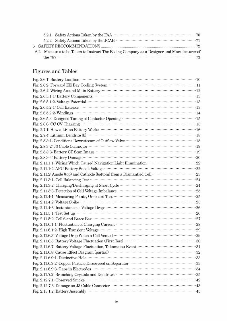
Fig. 2.6.1: Battery Location ································································································· 10
Fig. 2.6.2: Forward EE Bay Cooling System ········································································· 11
Fig. 2.6.4: Wiring Around Main Battery ··············································································· 12
Fig. 2.6.5.1-1: Battery Components ······················································································ 13
Fig. 2.6.5.1-2: Voltage Potential ··························································································· 13
Fig. 2.6.5.2-1: Cell Exterior ································································································· 13
Fig. 2.6.5.2-2: Windings ······································································································ 14
Fig. 2.6.5.3: Designed Timing of Contactor Opening ······························································ 15
Fig. 2.6.6: CC-CV Charging ································································································· 15
Fig. 2.7.1: How a Li-Ion Battery Works ················································································ 16
Fig. 2.7.4: Lithium Dendrite (b) ··························································································· 18
Fig. 2.8.3-1: Conditions Downstream of Outflow Valve ··························································· 18
Fig. 2.8.3-2: J3 Cable Connector ·························································································· 19
Fig. 2.8.3-3: Battery CT Scan Image ···················································································· 19
Fig. 2.8.3-4: Battery Damage······························································································· 20
Fig. 2.11.1-1: Wiring Which Caused Navigation Light Illumination ········································· 22
Fig. 2.11.1-2: APU Battery Sneak Voltage ············································································· 22
Fig. 2.11.2: Anode (top) and Cathode (bottom) from a Dismantled Cell····································· 23
Fig. 2.11.3-1: Cell Balancing Test ························································································· 24
Fig. 2.11.3-2: Charging/Discharging at Short Cycle ································································ 24
Fig. 2.11.3-3: Detection of Cell Voltage Imbalance ·································································· 25
Fig. 2.11.4-1: Measuring Points, On-board Test ····································································· 25
Fig. 2.11.4-2: Voltage Spike ································································································· 25
Fig. 2.11.4-3: Instantaneous Voltage Drop············································································· 26
Fig. 2.11.5-1: Test Set-up ····································································································· 26
Fig. 2.11.5-2: Cell 6 and Brace Bar ······················································································· 27
Fig. 2.11.6.1-1: Fluctuation of Charging Current ··································································· 28
Fig. 2.11.6.1-2: High Transient Voltage ················································································· 29
Fig. 2.11.6.3: Voltage Drop When a Cell Vented ····································································· 29
Fig. 2.11.6.5: Battery Voltage Fluctuation (First Test) ···························································· 30
Fig. 2.11.6.7: Battery Voltage Fluctuation, Takamatsu Event ················································· 31
Fig. 2.11.6.8: Cause-Effect Diagram (partial) ········································································ 32
Fig. 2.11.6.9-1: Distinctive Hole ··························································································· 33
Fig. 2.11.6.9-2: Copper Particle Discovered on Separator ························································ 33
Fig. 2.11.6.9-3: Gaps in Electrodes ······················································································· 34
Fig. 2.11.7.2: Branching Crystals and Dendrites ··································································· 35
Fig. 2.12.7.1: Observed Smoke ····························································································· 42
Fig. 2.12.7.3: Damage on J3 Cable Connector ······································································ 43
Fig. 2.13.1.2: Battery Assembly ··························································································· 45
v
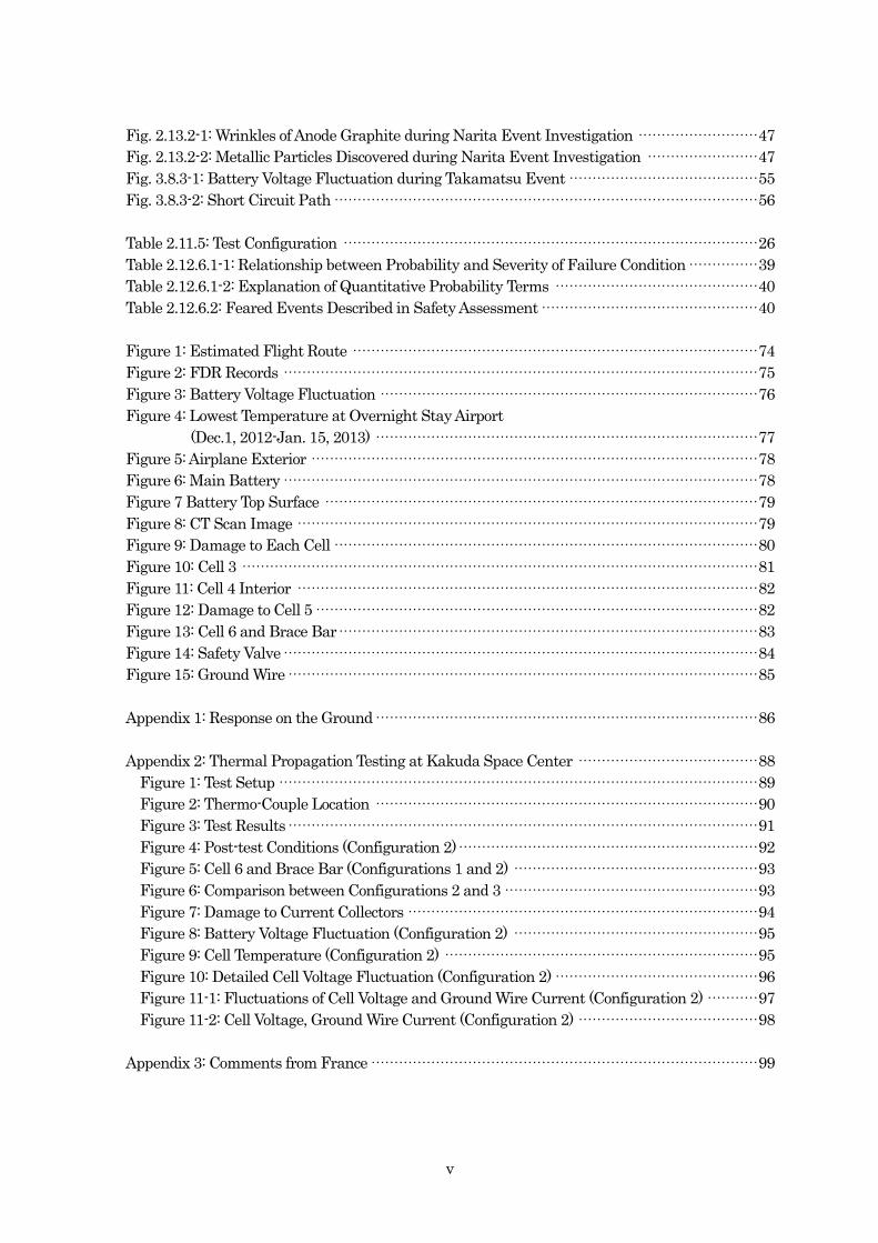
Fig. 2.13.2-1: Wrinkles of Anode Graphite during Narita Event Investigation ·························· 47
Fig. 2.13.2-2: Metallic Particles Discovered during Narita Event Investigation ························ 47
Fig. 3.8.3-1: Battery Voltage Fluctuation during Takamatsu Event ········································· 55
Fig. 3.8.3-2: Short Circuit Path ···························································································· 56
Table 2.11.5: Test Configuration ·························································································· 26
Table 2.12.6.1-1: Relationship between Probability and Severity of Failure Condition ··············· 39
Table 2.12.6.1-2: Explanation of Quantitative Probability Terms ············································ 40
Table 2.12.6.2: Feared Events Described in Safety Assessment ··············································· 40
Figure 1: Estimated Flight Route ························································································ 74
Figure 2: FDR Records ······································································································· 75
Figure 3: Battery Voltage Fluctuation ·················································································· 76
Figure 4: Lowest Temperature at Overnight Stay Airport
(Dec.1, 2012-Jan. 15, 2013) ··················································································· 77
Figure 5: Airplane Exterior ································································································· 78
Figure 6: Main Battery ······································································································· 78
Figure 7 Battery Top Surface ······························································································ 79
Figure 8: CT Scan Image ···································································································· 79
Figure 9: Damage to Each Cell ···························································································· 80
Figure 10: Cell 3 ················································································································ 81
Figure 11: Cell 4 Interior ···································································································· 82
Figure 12: Damage to Cell 5 ································································································ 82
Figure 13: Cell 6 and Brace Bar ··························································································· 83
Figure 14: Safety Valve ······································································································· 84
Figure 15: Ground Wire ······································································································ 85
Appendix 1: Response on the Ground ··················································································· 86
Appendix 2: Thermal Propagation Testing at Kakuda Space Center ······································· 88
Figure 1: Test Setup ········································································································ 89
Figure 2: Thermo-Couple Location ··················································································· 90
Figure 3: Test Results ······································································································ 91
Figure 4: Post-test Conditions (Configuration 2) ································································· 92
Figure 5: Cell 6 and Brace Bar (Configurations 1 and 2) ····················································· 93
Figure 6: Comparison between Configurations 2 and 3 ······················································· 93
Figure 7: Damage to Current Collectors ············································································ 94
Figure 8: Battery Voltage Fluctuation (Configuration 2) ····················································· 95
Figure 9: Cell Temperature (Configuration 2) ···································································· 95
Figure 10: Detailed Cell Voltage Fluctuation (Configuration 2) ············································ 96
Figure 11-1: Fluctuations of Cell Voltage and Ground Wire Current (Configuration 2) ··········· 97
Figure 11-2: Cell Voltage, Ground Wire Current (Configuration 2) ······································· 98
Appendix 3: Comments from France ···················································································· 99
1
1. PROCESS AND PROGRESS OF THE SERIOUS INCIDENT INVESTIGATION
1.1 Summary of the Serious Incident
On January 16 (Wednesday), 2013, a Boeing 787-8, operated by All Nippon
Airways Co., LTD., registered JA804A, took off from Yamaguchi-Ube Airport for
Tokyo international Airport at 08:11 local time (Japan Standard Time, UTC+9 hr) as
its scheduled flight 692. When it was climbing through 32,000 ft over Shikoku Island,
an EICAS message of battery failure came on at 08:27 accompanied by unusual
smell in the cockpit. The airplane diverted to Takamatsu Airport and landed there at
08:47. An emergency evacuation was executed using slides on T4 taxiway at 08:49.
Four passengers out of 137 occupants (Captain, seven crewmembers and 129
passengers) suffered minor injuries during the evacuation.
Although the main battery was damaged, it did not lead to a fire.
1.2 Outline of the Serious Incident Investigation
This event falls under the category of “A case where emergency evacuation was
conducted with the use for emergency evacuation slide,” as stipulated in Item (iv),
Article 166-4 of the Ordinance for Enforcement of the Civil Aeronautics Act, and is
classified as a serious incident.
1.2.1 Investigation Organization
On January 16, 2013, the Japan Transport Safety Board (JTSB) designated an
investigator-in-charge and four investigators to investigate this serious incident. On
January 28, it designated two additional investigators for the investigation.
On February 6, the JTSB also designated an expert advisor for detailed
investigation of lithium-ion battery:
Dr. Hitoshi Naito
Space Power System Group
Aerospace Research and Development Directorate
Japan Aerospace Exploration Agency (JAXA)
1.2.2 Representatives from Relevant States
Two accredited representatives from two States participated in this
investigation: one from the United States of America, as the State of design and
manufacture of the airplane, and the other from France, as the State of Design and
Manufacture of the electrical subsystem of the airplane.
1.2.3 Implementation of the Investigation
January 16-19, 2013: On-site investigation, airplane investigation,
and interviews at Takamatsu Airport
January 22-23: Battery computer tomography (CT) scanning at
JAXA
January 24-March 5: Battery examination at the manufacturer
2
January 26-27: Battery monitoring unit (BMU) examination
February 2-6: Battery charger unit (BCU) and bus power
control unit (BPCU) examination
February 16-17: Battery-BCU test
March 11-12: Progress meeting at the National
Transportation Safety Board (NTSB)
March 18-19: Airplane examination at Takamatsu Airport
April 8: Airplane examination at Takamatsu Airport
April 21-27: NTSB investigative hearing and progress
meeting
May 14-17: Battery examination
May 29-31: Examination of battery manufacturing
June 2-8: Progress meeting at Boeing
June 11-13: Battery examination
June 18-19 Battery examination
June 20: BMU examination and airplane examination
June 24-September 17: Battery test
November 1-28: Cell heat propagation test
1.2.4 Comments from the Parties Relevant to the Cause of the Serious Incident
Comments were invited from the parties relevant to the cause of the serious
incident.
1.2.5 Comments from the Relevant States
Comments were invited from the relevant States.
3
2. FACTUAL INFORMATION 2.1 History of the Flight
On January 16, 2013, a Boeing 787-8, operated by All Nippon Airways Co., LTD.
(hereinafter referred to as “ANA”), registered JA804A, took off from Yamaguchi-Ube
Airport for Tokyo International Airport at 08:11 as its scheduled flight 692. When it
was climbing through 32,000 ft around FIATO (waypoint, over Imabari City) an
instrument indication of battery failure came on at 08:27 accompanied by unusual
smell in the cockpit. The airplane diverted to Takamatsu Airport and landed there at
08:47. At 08:49 an emergency evacuation was executed on T4 taxiway.
The flight plan of the airplane was summarized as follows:
Flight rules: Instrument flight rules
Departure aerodrome: Yamaguchi-Ube Airport
Estimated off-block time: 08:00
Cruising speed: 493 kt
Cruising altitude: FL 410
Route: FIATO (waypoint) to Y16 (RNAV
route) to KTE (Kagawa VOR/DME) to
(further waypoints omitted)
Destination aerodrome: Tokyo International Airport
Estimated elapsed time: 1 hr 04 min
Alternate aerodrome: Narita International Airport
Fuel load expressed in endurance: 2 hr 39 min
Two pilots occupied the cockpit: the Captain in the left seat as the pilot flying
(PF, the pilot mainly in charge of flying), the first officer (FO) in the right seat as the
pilot monitor (PM, the pilot mainly in charge of duties other than flying).
The event developed as follows according to the enhanced airborne flight
recorder (EAFR 1 ) data, air traffic control (ATC) communications data, and
statements of flight and cabin crew.
2.1.1 History of Fight Based on Flight Recorder Data and ATC Communication Data
08:10:49 The airplane took off from runway 07, Yamaguchi-Ube Airport.
08:17:22 Fukuoka Air Traffic Control Center (ATCC) directed the airplane
to fly directly to Kagawa VOR/DME climbing to FL 410. The FO
repeated the direction.
08:26:31 The airplane was climbing through 32,000 ft at 1,500 fpm.
08:26:43 The FDR data shows that the main battery voltage began to drop
from 31 V (Main_Battery_voltage).
08:26:44 Main battery failure was detected (ELEC_MAIN_BATTERY).
08:26:51 Main battery voltage dropped to 11 V and leveled off.
08:26:54 The FO became aware of the indication of EMER LIGHTS2
1 EAFR has flight data recorder (FDR) function, cockpit voice recorder (CVR) function and data-link recorder
function. See section 2.9 for the details. 2 EMER LT is a lighting system to be turned on in case of loss of all electricity of the airplane. The system
4
(Illumination of emergency lights) on the engine indicating and
crew alerting system (EICAS3) screen.
08:27:09 He notified the Captain of the burning smell.
08:27:24 The FO voiced “ELEC MAIN BATTERY” and the Captain started
to select the nearest airport.
08:27:25 Detection of failed main battery was canceled.
08:27:31 Smoke detector downstream of forward electronic equipment
(EE) bay detected smoke and the master caution was illuminated
(SMOKE_EQUIP_CLG_FWD, Master_Caut_Act).
08:27:43 Main battery failure was detected again. Detection and cancelling
cycles repeated several times.
08:27:44 The Captain decided to divert to Takamatsu Airport.
08:27:52 Main battery discharge and abnormal voltage of the main battery
bus were detected. (MAIN_BATTERY_DISCH,
ELEC_HOT_BATTERY_BUS)
08:27:57 The airplane declared a state of emergency due to smoke
requesting a radar vector to Takamatsu Airport and emergency
descent.
08:28:06 After reaching 33,600 ft the airplane began to descent.
08:28:25 The main battery voltage fluctuated between 11 V and 26 V. (The
fluctuation continued until 08:35:29.)
08:28:28 Fukuoka ATCC directed the airplane to descend to FL 210. The
FO read back the direction.
08:29:03 Fukuoka ATCC directed the airplane to divert to Takamatsu
Airport via Kagawa VOR/DME. The FO read back the direction.
08:30:24 Smoke was again detected in the forward EE bay and the master
caution illuminated.
08:30:48 The FO notified a cabin attendant of the intended emergency
landing.
08:30:49 The airplane’s rate of descent reached 7,000 fpm when it was
descending through 23,000 ft.
08:31:56 Fukuoka ATCC directed the airplane to establish a radio contact
with Kansai Departure.
08:32:03 The airplane established a radio contact and informed of the
emergency and requested continued descent and a vector to
Takamatsu runway. Kansai Departure directed it to descend to
FL 150, followed by further descent to FL 130 for a radar vector to
the runway.
08:33:40 Kansai Departure directed the airplane to establish a radio
contact with Kansai Approach.
illuminates general area, aisles and doors to indicate their location. It is powered by the battery stored in
Wireless Control Unit. It is designed for the loss of a hot battery bus to activate the emergency lighting
system. 3 EICAS is an integrated system to provide flight crew with information on engine and other systems using
visual and aural methods.
5
08:33:53 The airplane established the radio contact with Kansai Approach
and reported on its emergency situation. It requested vector to
BRUTE (waypoint). Kansai Approach directed the airplane to
descend to 9,000 ft.
08:34:47 Kansai Approach directed the airplane to make a left turn to
BRUTE. Then it directed it to establish a radio contact with
Kansai Radar.
08:35:23 The airplane established the radio contact and reported on the
emergency situation. It requested the vectoring to runway 26 of
Takamatsu Airport and further descent. Kansai Radar started
the vectoring to the final approach course.
08:36:59 The FO made a public announcement saying that the airplane
would make an emergency landing at Takamatsu Airport.
08:37:50 The FO responded to the inquiry from Kansai Radar saying that:
the cockpit situation remained the same with thin smoke possibly
by an electric fire; the main battery had failed; there was a
possibility of erroneous instrument indications; they need to land
as soon as practicable.
08:40:50 Kansai Radar cleared the airplane to perform a visual approach
to Takamatsu Airport.
08:42:13 At pressure altitude 2,800 ft the auxiliary power unit (APU) was
started.
08:42:17 The airplane requested Takamatsu Airport Traffic Control Tower
for an emergency landing with a visual approach to runway 26.
The Tower directed the airplane to continue approach.
08:43:17 The Tower directed ANA 531 to execute a go-around, which was
approaching to runway 26.
08:43:51 The gear lever moved to DOWN position. Recorded main battery
voltage temporarily dropped to 3 V from 11 V and returned to 11
V.
08:43:53 The Tower cleared the airplane to land on runway 26 with the
wind information of 150 ° 4 kt.
08:45:21 The third smoke detection in the forward EE bay and the
illumination of the master caution light.
08:45:35 The autopilot was disengaged and this illuminated the master
warning light.
08:46:56 The airplane landed on runway 26.
08:47:06 The Tower, using the crash horn, informed the stations concerned
of its landing and the runway closure.
08:47:14 The airplane requested to vacate the runway into T4 taxiway to
stop there. The Tower approved the request.
08:47:45 The FO inquired the Tower whether it observed the smoke
coming from the airplane.
08:47:57 The Tower reported no smoke was visible.
08:48:03 The airplane taxied into T4 taxiway. The fourth EE bay smoke
6
was detected and the master caution light illuminated. The
condition of detection continued until the end of the recording.
08:48:07 The Tower visually recognized the smoke and directed the
airplane to stop there.
08:48:24 It stopped and parking brakes were set.
08:48:37 The Captain decided to execute an emergency evacuation and
made a public announcement to the passengers.
08:48:40 He executed the evacuation command.
08:49:00 Fuel flow to both engines was cut off.
08:49:09 Fire switch for #1 engine was pulled, followed by that of #2
engine.
The FDR records show that the temperature in the forward EE cooling system
duct remained around 25°C with small temperature fluctuation when the smoke
was detected during the period from the takeoff from Yamaguchi-Ube Airport to the
landing at Takamatsu Airport.
(See Figure 1: Estimated Flight Route, Figure 2: FDR Records)
2.1.2 Statements of Crewmembers
a. Flight Crew
The Captain reported to the operations room at Yamaguchi-Ube Airport
and started his pre-flight check. No anomalies were logged in the
maintenance log book.
The airplane was pushed back at 08:00 and took off at 08:10. When it
was climbing through 30,000 ft the FO and the Captain sensed a burning
smell of an electrical short circuit, followed by the EMER LT message on
the EICAS screen. When the FO opened the status page, he found several
messages. Next came the MAIN BATTERY DISCHARGE message.
Sometime later, SMOKE EQUIP COOLING FORWARD message
appeared. In case of on-board fire/smoke, the regulation requires diversion
to the nearest airport. The Captain reduced the climb rate to divert to the
suitable airport. When he looked forward he spotted Takamatsu Airport
just ahead. He decided to divert there. After some radio transmissions with
the air control authorities he received a radar vector to the airport. The
airplane received a clearance of an ILS runway 26 approach. With good
airport weather conditions flight crew were able to visually confirm the
airport.
Approximately 5 nm ahead of the airplane flew ANA flight 531 from
Tokyo. The airplane was supposed to land after flight 531 by visual
approach. When it aligned itself on the final approach course to runway 26,
Takamatsu Tower directed flight 531 to go around to give the first priority
of landing to the emergency airplane.
The Captain disengaged the autopilot sooner than usual as a
precaution based on the electrical system EICAS messages. Based on the
FO’s suggestion, the auxiliary power unit (APU) that is normally started
after the landing was started before the landing in order to secure the
7
electrical power. The landing was uneventful with normal instrument
readouts and breaking on the runway was done as usual.
There was no visible smoke in the cockpit during the flight. The fumes
lingered without increasing intensity. Cabin attendant’s (CA) report to the
Captain on the cabin situation indicated the same.
The Captain was ready to execute an emergency evacuation after the
landing. When he halted the airplane on T4 taxiway he asked the Tower
whether it could see the smoke coming out of the airplane. The Tower
initially reported no smoke was visible but later recognized the smoke. The
Captain also saw white smoke wafting beyond the right window near the
FO. He suspected an on-board fire and initiated the evacuation.
The evacuation started without delay in the passenger cabin. Both
flight crew run the evacuation check list and later moved to the passenger
cabin. The Captain helped the evacuation at cabin mid-section while the FO
the forward cabin. The Captain confirmed no remaining passengers in the
cabin, let the CAs evacuate and evacuated himself as the last person
Just after the evacuation large amount of smoke was observed, but it
became thinner as the time went by.
b. CAs
Fasten Seatbelt sign went off at 08:17 and each CA started to prepare
their service.
Around 08:25 the chief purser (CP) at 1L4 station received a Captain’s
interphone call about a burning smell in the cabin. As she was not able to
give a quick answer, she hung up the phone and went to 2R station for 2R
CA’s awareness. 2R CA sensed no smell in the forward-most galley, but
when she finished serving beverage in the forward cabin she sensed a
burning smell on the left aisle near the seat rows 1 and 2. She stated that it
was a faint smell which could be easily masked by the scent of coffee or miso
soup, both of which were being served then.
Four CAs in the aft cabin had the same awareness that they sensed the
weird smell. The 2L CA, who was directed by the CP to report the situation
to the Captain, reported the presence of unusual smell in the cabin.
At 08:37 an abrupt public announcement from the cockpit was made
without prior consultations with the CP, saying that the airplane would
divert to Takamatsu Airport due to the smoke detected on the airplane.
The CP questioned whether the Captain intended to launch an
emergency evacuation using slides at the airport, and he wanted
passengers to adopt brace position. He answered that he intended to make
a normal landing and in case of changed plan he would give instructions.
The CP disseminated his intention to all CAs over the intercom’s all-call
mode and directed them to prepare for the landing. Just after the direction,
4 The 787 has eight cabin doors with four doors on either side. Left doors are referred to as 1L-4L, while right
doors 1R-4R. 1L is the most forward cabin door on the left. Each CA is assigned to a door for emergency
evacuation.
8
4-chime sounded. (4-chime denotes that it is all right to walk around the
assigned area for landing preparation.) CAs started before-landing safety
check while 4R CA did the normal before-landing announcement. The
airplane landed at Takamatsu Airport at 08:47. After the landing the CP
gave a public announcement, “We have landed at Takamatsu Airport.
Please remain seated until the Captain turns off seat belt signs. I’ll give you
updates when they’re ready.”
The airplane stopped taxing. Approximately 30 sec later, evacuation
orders and signal sounded almost at the same time. The CP saw
something white outside of 1R door. She checked the outside situation and
started the emergency door opening. The CP was the first person who did
the emergency door opening. Although some CAs were not sure about the
validity of the evacuation orders and signal, they started door opening after
hearing the CP’s direction to do so. 4L door was not opened because there
were few passengers in its vicinity and the judgment to use other doors for
quick evacuation. The slides on the seven doors opened for the evacuation
operated normally.
No passengers were panicked. The first person standing at the top of
the slide didn’t jump. After the first one slid down, the remaining
passengers followed suit. Some passengers scared to slide down were
directed to sit on the door sill and CAs pushed them on the back. Some
passengers tried to bring their personal belongings, but CAs persuaded
them to abandon them. Female passengers putting on high-heeled shoes
slid after putting them off. Some male passengers supported the evacuation
at the bottom of the slide. The evacuation went on in an orderly manner.
Some CAs confirmed no remaining passengers in the restrooms or
passenger seats, and then jumped the slide with necessary gears.
Passengers were calm until the completion of the evacuation. On the
ground they started to shoot pictures roaming around the airplane. CAs
huddled them up near the airplane nose facing the airplane, made them in
10-person groups for head count. After being counted they were asked to sit
on the ground. All passengers were confirmed to have evacuated and so
were crew.
The Captain stood in front of the huddled passengers and explained
the situation. Passengers in the rear were explained later when he walked
to them. There were no passengers who requested English interpretation.
One CA stated that the airplane landed at 08:47; the Captain explained
the situation to the passengers at 08:58; evacuation itself seemed to have
done in 3 to 4 min followed by long head count.
The serious incident occurred on T4 taxiway in Takamatsu Airport at 08:49, on
January 16, 2013.
(See Figure 1: Estimated Flight Route)
2.2 Injuries to Persons
9
Four passengers suffered minor injuries when they landed after sliding down
the emergency evacuation slides.
2.3 Damage to the Airplane
2.3.1 Extent of Damage
Minor damage.
2.3.2 Damage to the Airplane Components
Main battery: Severe heat damage
Main battery ground wire: Fused open
2.4 Personnel Information
a. Captain Male, Age 53
Airline transport pilot certificate : March 12, 1997
Type rating for Boeing 787 November 30, 2012
Class 1 aviation medical certificate
Validity: Until August 4, 2013
Total flight time: 13,642 hr 46 min
Flight time in the last 30 days: 48 hr 22 min
Total flight time on the type: 55 hr 24 min
Flight time on the type in the last 30 days: 48 hr 22 min
b. FO Male, Age 46
Airline transport pilot certificate : March 15, 1999
Type rating for Boeing 787 August 31, 2011
Class 1 aviation medical certificate
Validity: Until August 5, 2013
Total flight time: 10,946 hr 04 min
Flight time in the last 30 days: 23 hr 29 min
Total flight time on the type: 475 hr 55 min
Flight time on the type in the last 30 days: 23 hr 29 min
2.5 Airplane Information
2.5.1 Airplane
a. Airplane type and others
Type: Boeing 787-8
Serial number: 34486
Date of manufacture: December 1, 2011
Certificate of airworthiness: No. 2012 – 004
Validity: From January 16, 2012 to the day
when the application of ANA’s
maintenance regulations expires
Category of airworthiness: Airplane, Transport Category T
Total flight time: 2,150 hr 45 min
Flight time since the last periodical check
(A02 inspections, October 29, 2012): 398 hr 40 min
10
b. Airplane history
The airplane was the ninth 787 built and was delivered to ANA as
JA804A on 14 January, 2012.
The incident battery (S/N 270) was manufactured and passed the
acceptance test procedures (ATP) on November 24, 2011 and was delivered
to ANA on February 3, 2012. It was in stock until October 16, 2012 as a
reserve part receiving maintenance care.
The original main battery delivered with the airplane on-board (S/N
240) was removed on October 17, 2012 following the malfunction in which
cockpit displays went black after the power-up. It had a total flight time of
1,694 hr and 12 min and 1,300 cycles. On the same day, main battery (S/N
270) was installed on the airplane. It had flight time of 456 hr 33 min and
371 cycles.
2.5.2 Weight and Balance
The weight of the airplane at the time of the serious incident was estimated to
be approximately 303,600 lb with the center of gravity (CG) at 22.1 % MAC, being
within the allowable limits. (Maximum certified weight is 370,000 lb. Allowable CG
range corresponding to this weight is between 6.0% and 36.9% MAC in longitudinal
axis.)
2.6 Boeing 787
2.6.1 General
The Boeing 787-8 (hereinafter referred to as “the 787”) is a twin-engine
commercial wide-body airplane. The 787 program started in April 2004, with its
maiden flight in December 2009. The type certificate was granted in August 2011.
The first delivery occurred in
September 2011. According to
Boeing the total number of
in-service 787 global fleet as of
January 16, 2013 was 50 with
combined flight time of
approximately
50,000 hr.
One of the characteristics of
the airplane is its reduced total weight to increase fuel efficiency. Composite
materials, limited hydraulic systems account for the reduced weight. Pneumatic
system was abandoned and replaced by electric systems. As the fuselage is made up
of composite material, cabin pressure and humidity is set higher than conventional
airplanes: approximately 0.8 atmospheric pressure and approximately 20%,
respectively.
Grounding to the fuselage is available any place for conventional
aluminum-based airplanes; however, 787’s composite fuselage makes it impossible
so that they use current return networks (CRN) for grounding terminal.
Main Battery APU Battery
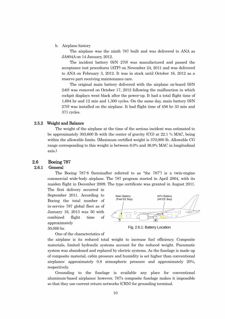
Fig. 2.6.1: Battery Location
(Aft EE Bay)(Fwd EE Bay)
Fig. 2.6.1: Battery Location
11
Transport category airplanes traditionally have used Ni-cd batteries as the
main battery and for starting an APU; 787s use light weight, high capacity lithium
ion batteries (LIBs). The main battery is identical to the APU battery. The main
battery is installed in the forward EE bay, while the APU battery is in the aft EE
bay.
The 787uses LIBs of significantly different design and capacity for applications
such as flight control electronics (FCE), recorder independent power supply (RIPS)
and emergency lights.
Boeing selected Thales Avionics Systems of France (hereinafter referred to as
“Thales”) as a supplier of the 787 power conversion subsystem, a part of the
airplane’s electrical power system in May, 2004. The use of LIBs was decided in
September the same year. Thales selected GS Yuasa Technology Ltd. (hereinafter
referred to as “GYT”) and Securaplane Technologies Inc. (hereinafter referred to as
“STI”) as LIB and BCU suppliers, respectively in January, 2005. Boeing participated
in the selection process and did not object to Thales’s decision to select these
suppliers.
The incident battery was the third-generation battery (first generation, mass
production model) counted from the developmental phase. The first-generation
battery passed the critical design review in November, 2005. Next year an incident
occurred at STI. The battery was overcharged and resulted in fire because a signal
wire between the battery and the BCU was not connected and the battery was
charged resulting in overcharging and fire. The second-generation developmental
battery was developed through design change with addition of a contactor and
sub-BMU (BMU 3).
However, in 2009, an incident occurred at UTC Aerospace Systems Airplane
Power Systems Integration Facility (APSIF) in the United States of America, in
which a battery cell vented5 with leaked electrolyte and smoke. The investigation
revealed that repeated over-discharging followed by high current recharge may have
resulted in copper-dissolving into electrolyte which led to internal short circuits.
After the incident, following corrective design changes were made: BDM was
inserted to block charging currents from the hot battery bus (HBB); a circuit to
monitor the BDM was added to the BMU; the latch mechanism was added to the
BMU to avoid recharging after
over-discharging; and battery box sealing
was added. With these modifications the
battery evolved into the third generation.
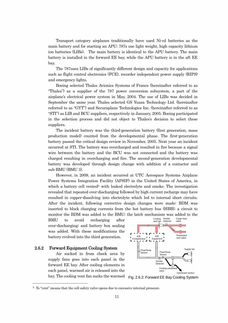
2.6.2 Forward Equipment Cooling System
Air sucked in from cheek area by
supply fans goes into each panel in the
forward EE bay. After cooling elements in
each panel, warmed air is released into the
bay. The cooling vent fan sucks the warmed
5 To “vent” means that the cell safety valve opens due to excessive internal pressure.
E/ECompartment
E/EEquipment
Flow/TempSensor
SmokeDetector
Flow/TempSensor
SmokeDetector
Coolingvent fan
Cargo heatvalve
Overboardvent valve
Supply fan
Overboard venturi
Cooling overboardvalve
Fig. 2.6.2: Forward EE Bay Cooling System
12
air and pushes it to forward to outflow valve and forward cargo bay.
The air sucked in passes through a smoke detector before going into the forward
EE bay. The warmed air sucked from the bay goes through the smoke detector
downstream of the exhaust fan.
In case of smoke detection in the bay, normally closed override valve opens and
some of the warm air is sucked overboard through the forward override valve by
Venturi effect and the rest by the cooling vent fan.
2.6.3 Electrical Power Systems
The Electrical Power Generation and Start System (EPGSS) consists of unique
electrical components that generate, control and protect airplane power, and supply
power to start the main and APU engines. The EPGSS includes the following
components:
Four (4) Variable Frequency Starter Generators (VFSGs),
Two (2) APU Starter Generators (ASGs),
Six (6) Generator Control Units (GCUs),
In the extremely improbable event that all four VFSGs fail and main AC power
is temporarily lost, the ASGs provide backup power. If the ASGs fail for any reason,
including if the APU battery is unavailable to start them, the airplane is equipped
with a hybrid 10kVA Ram Air Turbine (RAT) generator/hydraulic pump that can
provide the airplane with power. The main battery’s only role in a power failure is to
support standby operations, including main engine igniters. The Main and APU
battery ratings are 50 amp-hours at end-of-life.
Main battery discharging currents during normal flight operation is several
Amps with temporary peak of approximately 100 A.
An APU start using the APU battery scenario consists of two failed APU start
attempts which can be followed by another attempt after having a 5-minute rest.
The APU battery draws approximately 600 A of currents.
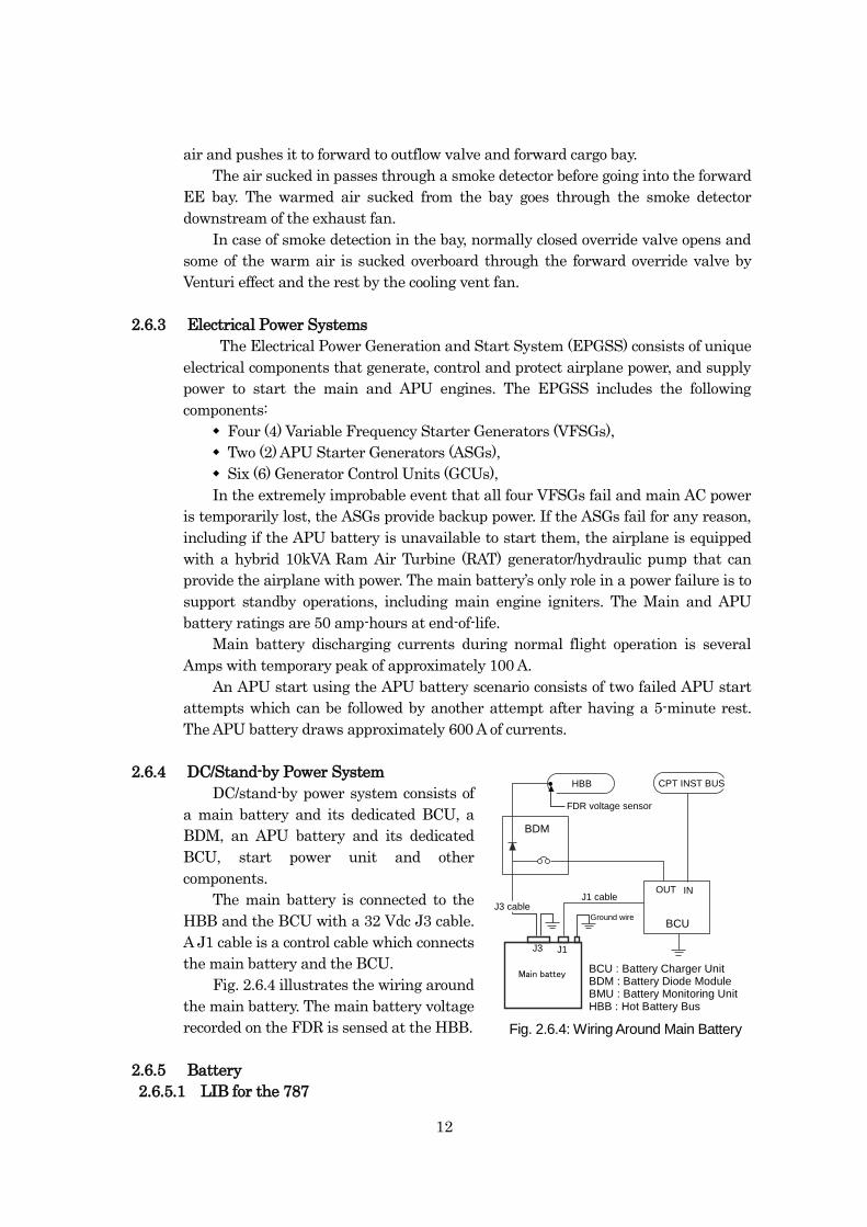
2.6.4 DC/Stand-by Power System
DC/stand-by power system consists of
a main battery and its dedicated BCU, a
BDM, an APU battery and its dedicated
BCU, start power unit and other
components.
The main battery is connected to the
HBB and the BCU with a 32 Vdc J3 cable.
A J1 cable is a control cable which connects
the main battery and the BCU.
Fig. 2.6.4 illustrates the wiring around
the main battery. The main battery voltage
recorded on the FDR is sensed at the HBB.
2.6.5 Battery
2.6.5.1 LIB for the 787
OUT IN
BCU
HBB
BDM
Main battey
J1 cableJ3 cable
BCU : Battery Charger UnitBDM : Battery Diode ModuleBMU : Battery Monitoring UnitHBB : Hot Battery Bus
J3 J1
CPT INST BUS
Fig. 2.6.4: Wiring around Main Battery
FDR voltage sensor
Ground wire
Fig. 2.6.4: Wiring Around Main Battery
13
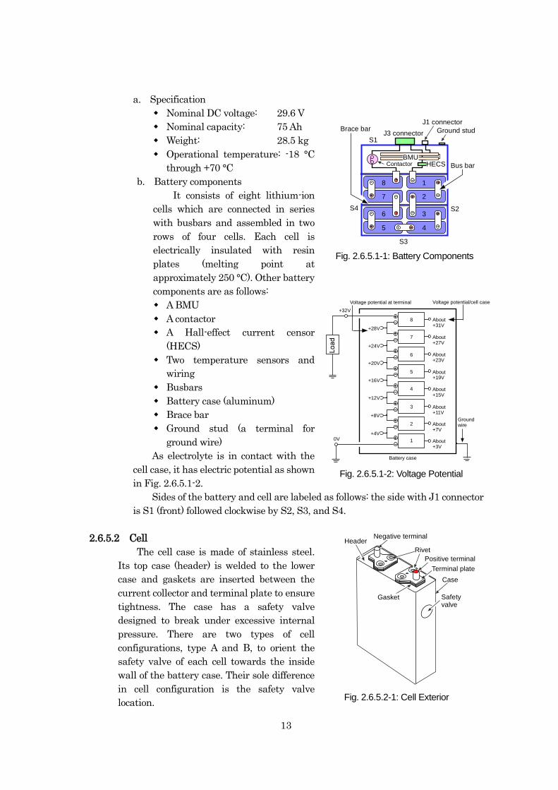
a. Specification
Nominal DC voltage: 29.6 V
Nominal capacity: 75 Ah
Weight: 28.5 kg
Operational temperature: -18 °C
through +70 °C
b. Battery components
It consists of eight lithium-ion
cells which are connected in series
with busbars and assembled in two
rows of four cells. Each cell is
electrically insulated with resin
plates (melting point at
approximately 250 °C). Other battery
components are as follows:
A BMU
A contactor
A Hall-effect current censor
(HECS)
Two temperature sensors and
wiring
Busbars
Battery case (aluminum)
Brace bar
Ground stud (a terminal for
ground wire)
As electrolyte is in contact with the
cell case, it has electric potential as shown
in Fig. 2.6.5.1-2.
Sides of the battery and cell are labeled as follows: the side with J1 connector
is S1 (front) followed clockwise by S2, S3, and S4.
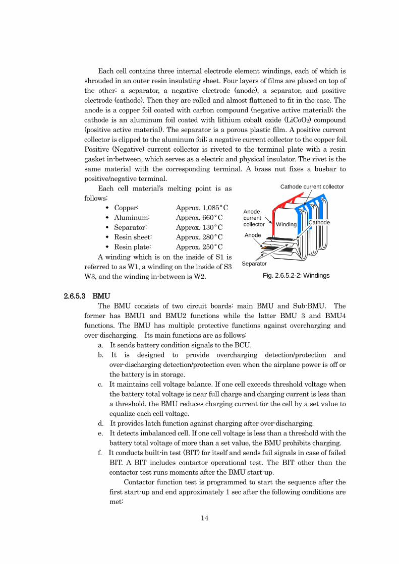
2.6.5.2 Cell
The cell case is made of stainless steel.
Its top case (header) is welded to the lower
case and gaskets are inserted between the
current collector and terminal plate to ensure
tightness. The case has a safety valve
designed to break under excessive internal
pressure. There are two types of cell
configurations, type A and B, to orient the
safety valve of each cell towards the inside
wall of the battery case. Their sole difference
in cell configuration is the safety valve
location.
8 About+31V
7 About+27V
6 About+23V
5 About+19V
4 About+15V
3 About+11V
2 About+7V
1 About+3V
+28V
+24V
+20V
+16V
+12V
+8V
+4V
Battery case
Voltage potential/cell caseVoltage potential at terminal
+32V
0V
Groundwire
Fig. 2.6-6: Cell
Case
HeaderNegative terminal
Rivet
Gasket
Positive terminal
Terminal plate
Safetyvalve
1
2
3
45
6
7
8
S1
S2
S3
S4
BMUHECS
J3 connector
Contactor
J1 connectorBrace bar
Bus bar
Ground stud
Fig. 2.6.5.1-1: Battery Components
Fig. 2.6.5.1-2: Voltage Potential
Fig. 2.6.5.2-1: Cell Exterior
14
Each cell contains three internal electrode element windings, each of which is
shrouded in an outer resin insulating sheet. Four layers of films are placed on top of
the other: a separator, a negative electrode (anode), a separator, and positive
electrode (cathode). Then they are rolled and almost flattened to fit in the case. The
anode is a copper foil coated with carbon compound (negative active material); the
cathode is an aluminum foil coated with lithium cobalt oxide (LiCoO2) compound
(positive active material). The separator is a porous plastic film. A positive current
collector is clipped to the aluminum foil; a negative current collector to the copper foil.
Positive (Negative) current collector is riveted to the terminal plate with a resin
gasket in-between, which serves as a electric and physical insulator. The rivet is the
same material with the corresponding terminal. A brass nut fixes a busbar to
positive/negative terminal.
Each cell material’s melting point is as
follows:
Copper: Approx. 1,085°C
Aluminum: Approx. 660°C
Separator: Approx. 130°C
Resin sheet: Approx. 280°C
Resin plate: Approx. 250°C
A winding which is on the inside of S1 is
referred to as W1, a winding on the inside of S3
W3, and the winding in-between is W2.
2.6.5.3 BMU
The BMU consists of two circuit boards: main BMU and Sub-BMU. The
former has BMU1 and BMU2 functions while the latter BMU 3 and BMU4
functions. The BMU has multiple protective functions against overcharging and
over-discharging. Its main functions are as follows:
a. It sends battery condition signals to the BCU.
b. It is designed to provide overcharging detection/protection and
over-discharging detection/protection even when the airplane power is off or
the battery is in storage.
c. It maintains cell voltage balance. If one cell exceeds threshold voltage when
the battery total voltage is near full charge and charging current is less than
a threshold, the BMU reduces charging current for the cell by a set value to
equalize each cell voltage.
d. It provides latch function against charging after over-discharging.
e. It detects imbalanced cell. If one cell voltage is less than a threshold with the
battery total voltage of more than a set value, the BMU prohibits charging.
f. It conducts built-in test (BIT) for itself and sends fail signals in case of failed
BIT. A BIT includes contactor operational test. The BIT other than the
contactor test runs moments after the BMU start-up.
Contactor function test is programmed to start the sequence after the
first start-up and end approximately 1 sec after the following conditions are
met:
Separator
Anode
Cathode
Anodecurrentcollector
Cathode current collector
Winding
Fig. 2.6.5.2-2: WindingsFig. 2.6.5.2-2: Windings
15
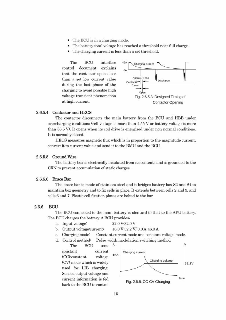
The BCU is in a charging mode.
The battery total voltage has reached a threshold near full charge.
The charging current is less than a set threshold.
The BCU interface
control document explains
that the contactor opens less
than a set low current value
during the last phase of the
charging to avoid possible high
voltage transient phenomenon
at high current.
2.6.5.4 Contactor and HECS
The contactor disconnects the main battery from the BCU and HBB under
overcharging conditions (cell voltage is more than 4.55 V or battery voltage is more
than 36.5 V). It opens when its coil drive is energized under non-normal conditions.
It is normally closed.
HECS measures magnetic flux which is in proportion to the magnitude current,
convert it to current value and send it to the BMU and the BCU.
2.6.5.5 Ground Wire
The battery box is electrically insulated from its contents and is grounded to the
CRN to prevent accumulation of static charges.
2.6.5.6 Brace Bar
The brace bar is made of stainless steel and it bridges battery box S2 and S4 to
maintain box geometry and to fix cells in place. It extends between cells 2 and 3, and
cells 6 and 7. Plastic cell fixation plates are bolted to the bar.
2.6.6 BCU
The BCU connected to the main battery is identical to that to the APU battery.
The BCU charges the battery. A BCU provides:
a. Input voltage: 22.0 V-32.0 V
b. Output voltage/current: 16.0 V-32.2 V/ 0.0 A-46.0 A
c. Charging mode: Constant current mode and constant voltage mode.
d. Control method: Pulse-width modulation switching method
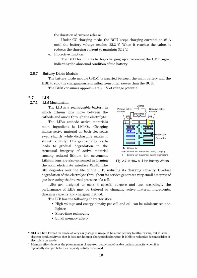
The BCU uses
constant current
(CC)-constant voltage
(CV) mode which is widely
used for LIB charging.
Sensed output voltage and
current information is fed
back to the BCU to control
Open
Contactor
Charging current46A
0A
Close
DischargeApprox. 1 sec
Fig. 2.6.5.3: Designed Timing of
Contactor Opening
Charging current
Charging voltage
Fig. 2.6-9: CC-CV ChargingTime
A V
46A
32.2V
Fig. 2.6.6: CC-CV Charging
16
the duration of current release.
Under CC charging mode, the BCU keeps charging currents at 46 A
until the battery voltage reaches 32.2 V. When it reaches the value, it
reduces the charging current to maintain 32.2 V.
e. Protective function
The BCU terminates battery charging upon receiving the BMU signal
indicating the abnormal condition of the battery.
2.6.7 Battery Diode Module
The battery diode module (BDM) is inserted between the main battery and the
HBB to stop the charging current influx from other sauces than the BCU.
The BDM consumes approximately 1 V of voltage potential.
2.7 LIB
2.7.1 LIB Mechanism
The LIB is a rechargeable battery in
which lithium ions move between the
cathode and anode through the electrolyte.
The LIB’s cathode active material’s
main ingredient is LiCoO2. Charging
makes active material on both electrodes
swell slightly while discharging makes it
shrink slightly. Charge-discharge cycle
leads to gradual degradation in the
structural integrity of active material
causing reduced lithium ion movement.
Lithium ions are also consumed in forming
the solid electrolyte interface (SEI6). The
SEI degrades over the life of the LIB, reducing its charging capacity. Gradual
degradation of the electrolyte throughout its service generates very small amounts of
gas increasing the internal pressure of a cell.
LIBs are designed to meet a specific purpose and use, accordingly the
performance of LIBs may be tailored by changing active material ingredients,
charging capacity and charging method.
The LIB has the following characteristics:
High voltage and energy density per cell and cell can be miniaturized and
lighter.
Short-time recharging
Small memory effect7
6 SEI is a film formed on anode at very early stage of usage. It has conductivity to lithium-ions, but it lacks
electron conductivity so that it does not hamper charging/discharging. It inhibits reductive decomposition of
electrolyte on anode. 7 Memory effect denotes the phenomenon of apparent reduction of usable battery capacity when it is
repeatedly charged before its capacity is fully consumed.
Lithium ion
Charge
Discharge
Electrolyte
Separator
Fig. 2.7.1: How a Lithium Ion Battery Works
Negative activematerial
Positive activematerial
Lithium ion movement during charging
Lithimu ion movement during discharging
Fig. 2.7.1: How a Li-ion Battery Works
Charging
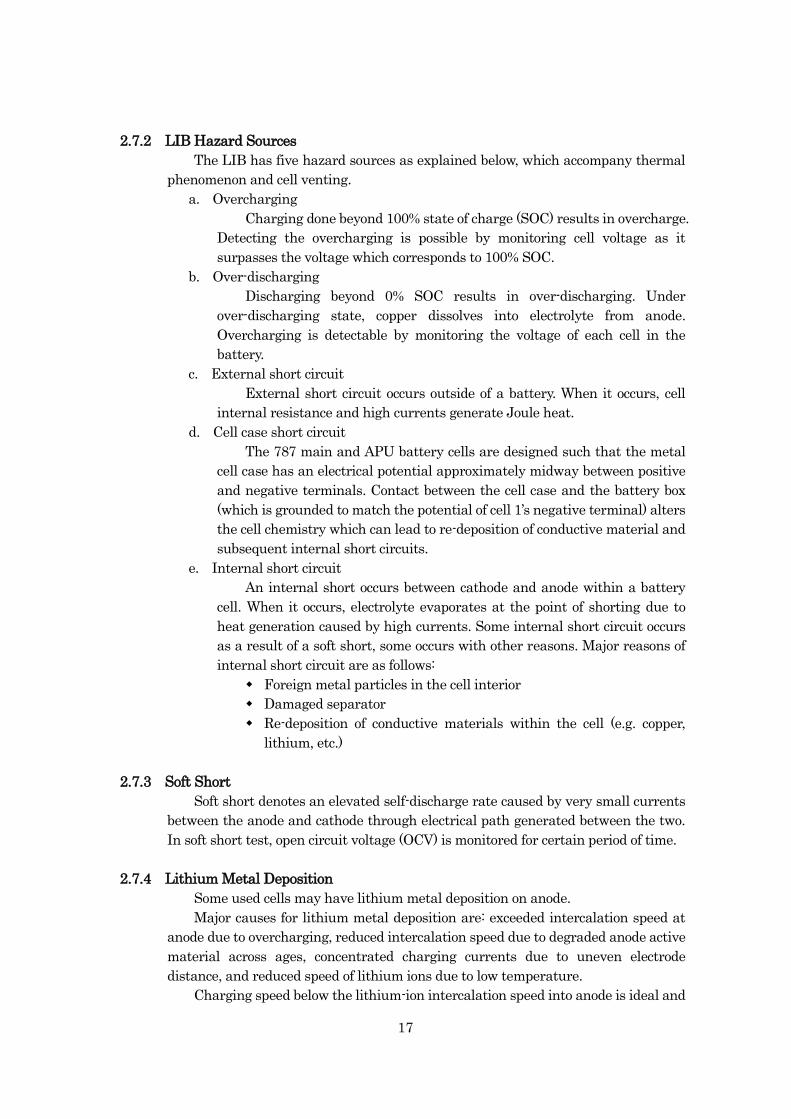
17
2.7.2 LIB Hazard Sources
The LIB has five hazard sources as explained below, which accompany thermal
phenomenon and cell venting.
a. Overcharging
Charging done beyond 100% state of charge (SOC) results in overcharge.
Detecting the overcharging is possible by monitoring cell voltage as it
surpasses the voltage which corresponds to 100% SOC.
b. Over-discharging
Discharging beyond 0% SOC results in over-discharging. Under
over-discharging state, copper dissolves into electrolyte from anode.
Overcharging is detectable by monitoring the voltage of each cell in the
battery.
c. External short circuit
External short circuit occurs outside of a battery. When it occurs, cell
internal resistance and high currents generate Joule heat.
d. Cell case short circuit
The 787 main and APU battery cells are designed such that the metal
cell case has an electrical potential approximately midway between positive
and negative terminals. Contact between the cell case and the battery box
(which is grounded to match the potential of cell 1’s negative terminal) alters
the cell chemistry which can lead to re-deposition of conductive material and
subsequent internal short circuits.
e. Internal short circuit
An internal short occurs between cathode and anode within a battery
cell. When it occurs, electrolyte evaporates at the point of shorting due to
heat generation caused by high currents. Some internal short circuit occurs
as a result of a soft short, some occurs with other reasons. Major reasons of
internal short circuit are as follows:
Foreign metal particles in the cell interior
Damaged separator
Re-deposition of conductive materials within the cell (e.g. copper,
lithium, etc.)
2.7.3 Soft Short
Soft short denotes an elevated self-discharge rate caused by very small currents
between the anode and cathode through electrical path generated between the two.
In soft short test, open circuit voltage (OCV) is monitored for certain period of time.
2.7.4 Lithium Metal Deposition
Some used cells may have lithium metal deposition on anode.
Major causes for lithium metal deposition are: exceeded intercalation speed at
anode due to overcharging, reduced intercalation speed due to degraded anode active
material across ages, concentrated charging currents due to uneven electrode
distance, and reduced speed of lithium ions due to low temperature.
Charging speed below the lithium-ion intercalation speed into anode is ideal and
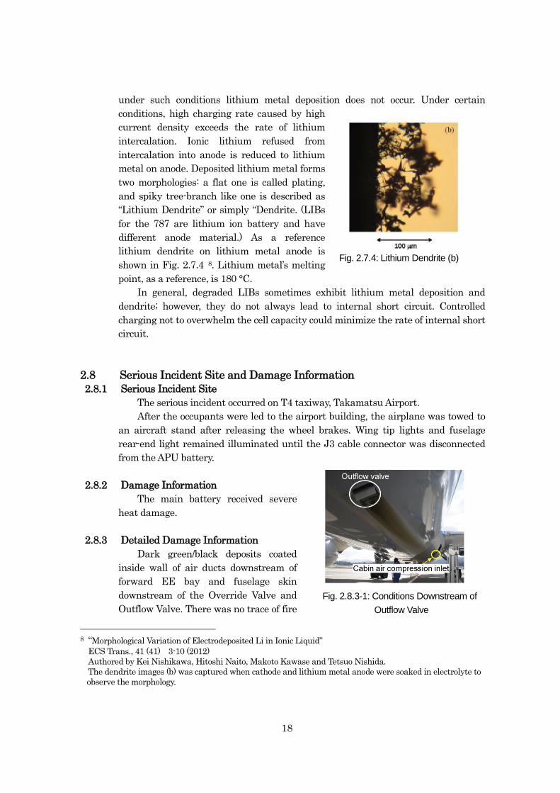
18
under such conditions lithium metal deposition does not occur. Under certain
conditions, high charging rate caused by high
current density exceeds the rate of lithium
intercalation. Ionic lithium refused from
intercalation into anode is reduced to lithium
metal on anode. Deposited lithium metal forms
two morphologies: a flat one is called plating,
and spiky tree-branch like one is described as
“Lithium Dendrite” or simply “Dendrite. (LIBs
for the 787 are lithium ion battery and have
different anode material.) As a reference
lithium dendrite on lithium metal anode is
shown in Fig. 2.7.4 8. Lithium metal’s melting
point, as a reference, is 180 °C.
In general, degraded LIBs sometimes exhibit lithium metal deposition and
dendrite; however, they do not always lead to internal short circuit. Controlled
charging not to overwhelm the cell capacity could minimize the rate of internal short
circuit.
2.8 Serious Incident Site and Damage Information
2.8.1 Serious Incident Site
The serious incident occurred on T4 taxiway, Takamatsu Airport.
After the occupants were led to the airport building, the airplane was towed to
an aircraft stand after releasing the wheel brakes. Wing tip lights and fuselage
rear-end light remained illuminated until the J3 cable connector was disconnected
from the APU battery.
2.8.2 Damage Information
The main battery received severe
heat damage.
2.8.3 Detailed Damage Information
Dark green/black deposits coated
inside wall of air ducts downstream of
forward EE bay and fuselage skin
downstream of the Override Valve and
Outflow Valve. There was no trace of fire
8 “Morphological Variation of Electrodeposited Li in Ionic Liquid”
ECS Trans., 41 (41) 3-10 (2012)
Authored by Kei Nishikawa, Hitoshi Naito, Makoto Kawase and Tetsuo Nishida.
The dendrite images (b) was captured when cathode and lithium metal anode were soaked in electrolyte to
observe the morphology.
Fig. 2.7.4: Lithium Dendrite (b)
Fig. 2.8.3-1: Conditions Downstream of
Outflow Valve
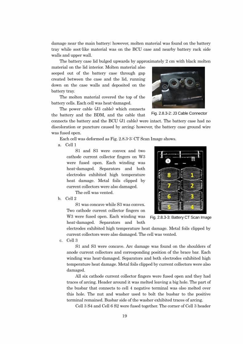
19
damage near the main battery; however, molten material was found on the battery
tray while soot-like material was on the BCU case and nearby battery rack side
walls and upper wall.
The battery case lid bulged upwards by approximately 2 cm with black molten
material on the lid interior. Molten material also
seeped out of the battery case through gap
created between the case and the lid, running
down on the case walls and deposited on the
battery tray.
The molten material covered the top of the
battery cells. Each cell was heat-damaged.
The power cable (J3 cable) which connects
the battery and the BDM, and the cable that
connects the battery and the BCU (J1 cable) were intact. The battery case had no
discoloration or puncture caused by arcing; however, the battery case ground wire
was fused open.
Each cell was deformed as Fig. 2.8.3-3: CT Scan Image shows.
a. Cell 1
S1 and S3 were convex and two
cathode current collector fingers on W3
were fused open. Each winding was
heat-damaged. Separators and both
electrodes exhibited high temperature
heat damage. Metal foils clipped by
current collectors were also damaged.
The cell was vented.
b. Cell 2
S1 was concave while S3 was convex.
Two cathode current collector fingers on
W3 were fused open. Each winding was
heat-damaged. Separators and both
electrodes exhibited high temperature heat damage. Metal foils clipped by
current collectors were also damaged. The cell was vented.
c. Cell 3
S1 and S3 were concave. Arc damage was found on the shoulders of
anode current collectors and corresponding position of the brace bar. Each
winding was heat-damaged. Separators and both electrodes exhibited high
temperature heat damage. Metal foils clipped by current collectors were also
damaged.
All six cathode current collector fingers were fused open and they had
traces of arcing. Header around it was melted leaving a big hole. The part of
the busbar that connects to cell 4 negative terminal was olso melted over
this hole. The nut and washer used to bolt the busbar to the positive
terminal remained. Busbar side of the washer exhibited traces of arcing.
Cell 3 S4 and Cell 6 S2 were fused together. The corner of Cell 3 header
Fig. 2.8.3-2: J3 Cable Connector
Fig. 2.8.3-3: Battery CT Scan Image
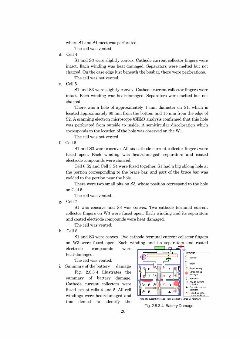
20
where S1 and S4 meet was perforated.
The cell was vented
d. Cell 4
S1 and S3 were slightly convex. Cathode current collector fingers were
intact. Each winding was heat-damaged. Separators were melted but not
charred. On the case edge just beneath the busbar, there were perforations.
The cell was not vented.
e. Cell 5
S1 and S3 were slightly convex. Cathode current collector fingers were
intact. Each winding was heat-damaged. Separators were melted but not
charred.
There was a hole of approximately 1 mm diameter on S1, which is
located approximately 80 mm from the bottom and 15 mm from the edge of
S2. A scanning electron microscope (SEM) analysis confirmed that this hole
was perforated from outside to inside. A semicircular discoloration which
corresponds to the location of the hole was observed on the W1.
The cell was not vented.
f. Cell 6
S1 and S3 were concave. All six cathode current collector fingers were
fused open. Each winding was heat-damaged: separators and coated
electrode compounds were charred.
Cell 6 S2 and Cell 3 S4 were fused together. S1 had a big oblong hole at
the portion corresponding to the brace bar, and part of the brace bar was
welded to the portion near the hole.
There were two small pits on S3, whose position correspond to the hole
on Cell 5.
The cell was vented.
g. Cell 7
S1 was concave and S3 was convex. Two cathode terminal current
collector fingers on W3 were fused open. Each winding and its separators
and coated electrode compounds were heat-damaged.
The cell was vented.
h. Cell 8
S1 and S3 were convex. Two cathode terminal current collector fingers
on W3 were fused open. Each winding and its separators and coated
electrode compounds were
heat-damaged.
The cell was vented.
i. Summary of the battery damage
Fig. 2.8.3-4 illustrates the
summary of battery damage.
Cathode current collectors were
fused except cells 4 and 5. All cell
windings were heat-damaged and
this denied to identify the Fig. 2.8.3-4: Battery Damage
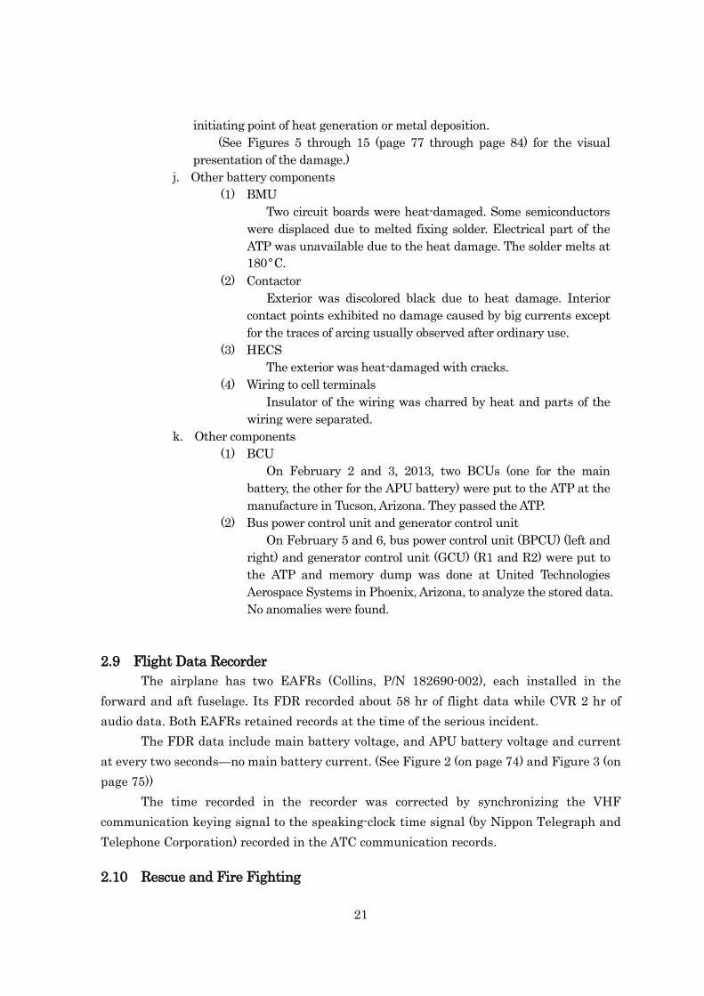
21
initiating point of heat generation or metal deposition.
(See Figures 5 through 15 (page 77 through page 84) for the visual
presentation of the damage.)
j. Other battery components
(1) BMU
Two circuit boards were heat-damaged. Some semiconductors
were displaced due to melted fixing solder. Electrical part of the
ATP was unavailable due to the heat damage. The solder melts at
180°C.
(2) Contactor
Exterior was discolored black due to heat damage. Interior
contact points exhibited no damage caused by big currents except
for the traces of arcing usually observed after ordinary use.
(3) HECS
The exterior was heat-damaged with cracks.
(4) Wiring to cell terminals
Insulator of the wiring was charred by heat and parts of the
wiring were separated.
k. Other components
(1) BCU
On February 2 and 3, 2013, two BCUs (one for the main
battery, the other for the APU battery) were put to the ATP at the
manufacture in Tucson, Arizona. They passed the ATP.
(2) Bus power control unit and generator control unit
On February 5 and 6, bus power control unit (BPCU) (left and
right) and generator control unit (GCU) (R1 and R2) were put to
the ATP and memory dump was done at United Technologies
Aerospace Systems in Phoenix, Arizona, to analyze the stored data.
No anomalies were found.
2.9 Flight Data Recorder
The airplane has two EAFRs (Collins, P/N 182690-002), each installed in the
forward and aft fuselage. Its FDR recorded about 58 hr of flight data while CVR 2 hr of
audio data. Both EAFRs retained records at the time of the serious incident.
The FDR data include main battery voltage, and APU battery voltage and current
at every two seconds—no main battery current. (See Figure 2 (on page 74) and Figure 3 (on
page 75))
The time recorded in the recorder was corrected by synchronizing the VHF
communication keying signal to the speaking-clock time signal (by Nippon Telegraph and
Telephone Corporation) recorded in the ATC communication records.
2.10 Rescue and Fire Fighting
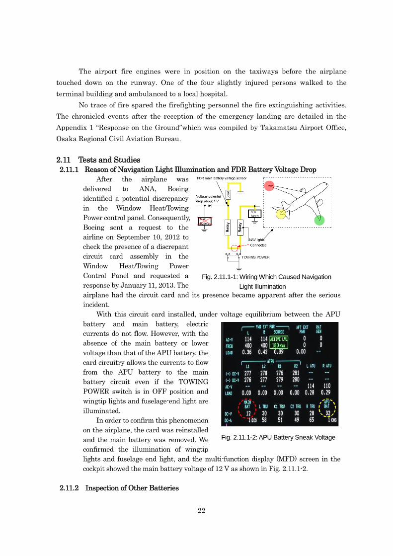
22
The airport fire engines were in position on the taxiways before the airplane
touched down on the runway. One of the four slightly injured persons walked to the
terminal building and ambulanced to a local hospital.
No trace of fire spared the firefighting personnel the fire extinguishing activities.
The chronicled events after the reception of the emergency landing are detailed in the
Appendix 1 “Response on the Ground”which was compiled by Takamatsu Airport Office,
Osaka Regional Civil Aviation Bureau.
2.11 Tests and Studies
2.11.1 Reason of Navigation Light Illumination and FDR Battery Voltage Drop
After the airplane was
delivered to ANA, Boeing
identified a potential discrepancy
in the Window Heat/Towing
Power control panel. Consequently,
Boeing sent a request to the
airline on September 10, 2012 to
check the presence of a discrepant
circuit card assembly in the
Window Heat/Towing Power
Control Panel and requested a
response by January 11, 2013. The
airplane had the circuit card and its presence became apparent after the serious
incident.
With this circuit card installed, under voltage equilibrium between the APU
battery and main battery, electric
currents do not flow. However, with the
absence of the main battery or lower
voltage than that of the APU battery, the
card circuitry allows the currents to flow
from the APU battery to the main
battery circuit even if the TOWING
POWER switch is in OFF position and
wingtip lights and fuselage-end light are
illuminated.
In order to confirm this phenomenon
on the airplane, the card was reinstalled
and the main battery was removed. We
confirmed the illumination of wingtip
lights and fuselage end light, and the multi-function display (MFD) screen in the
cockpit showed the main battery voltage of 12 V as shown in Fig. 2.11.1-2.
2.11.2 Inspection of Other Batteries
Fig. 2.11.1-1: Wiring Which Caused Navigation
Light Illumination
Fig. 2.11.1-2: APU Battery Sneak Voltage
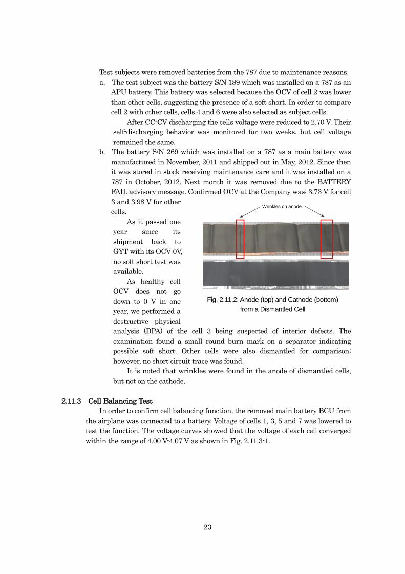
23
Test subjects were removed batteries from the 787 due to maintenance reasons.
a. The test subject was the battery S/N 189 which was installed on a 787 as an
APU battery. This battery was selected because the OCV of cell 2 was lower
than other cells, suggesting the presence of a soft short. In order to compare
cell 2 with other cells, cells 4 and 6 were also selected as subject cells.
After CC-CV discharging the cells voltage were reduced to 2.70 V. Their
self-discharging behavior was monitored for two weeks, but cell voltage
remained the same.
b. The battery S/N 269 which was installed on a 787 as a main battery was
manufactured in November, 2011 and shipped out in May, 2012. Since then
it was stored in stock receiving maintenance care and it was installed on a
787 in October, 2012. Next month it was removed due to the BATTERY
FAIL advisory message. Confirmed OCV at the Company was: 3.73 V for cell
3 and 3.98 V for other
cells.
As it passed one
year since its
shipment back to
GYT with its OCV 0V,
no soft short test was
available.
As healthy cell
OCV does not go
down to 0 V in one
year, we performed a
destructive physical
analysis (DPA) of the cell 3 being suspected of interior defects. The
examination found a small round burn mark on a separator indicating
possible soft short. Other cells were also dismantled for comparison;
however, no short circuit trace was found.
It is noted that wrinkles were found in the anode of dismantled cells,
but not on the cathode.
2.11.3 Cell Balancing Test
In order to confirm cell balancing function, the removed main battery BCU from
the airplane was connected to a battery. Voltage of cells 1, 3, 5 and 7 was lowered to
test the function. The voltage curves showed that the voltage of each cell converged
within the range of 4.00 V-4.07 V as shown in Fig. 2.11.3-1.
Fig. 2.11.3: Anode (top) and Cathode
(bottom) from a Damaged Cell
Fig. 2.11.2: Anode (top) and Cathode (below) from aDismantled Cell
Wrinkles on anode
Fig. 2.11.2: Anode (top) and Cathode (bottom)
from a Dismantled Cell
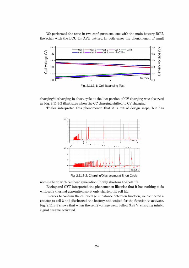
24
We performed the tests in two configurations: one with the main battery BCU,
the other with the BCU for APU battery. In both cases the phenomenon of small
charging/discharging in short cycle at the last portion of CV charging was observed
as Fig. 2.11.3-2 illustrates when the CC charging shifted to CV charging.
Thales interpreted this phenomenon that it is out of design scope, but has
nothing to do with cell heat generation. It only shortens the cell life.
Boeing and GYT interpreted the phenomenon likewise that it has nothing to do
with cell’s thermal generation ant it only shorten the cell life.
In order to confirm the cell voltage imbalance detection function, we connected a
resistor to cell 2 and discharged the battery and waited for the function to activate.
Fig. 2.11.3-3 shows that when the cell 2 voltage went bellow 3.89 V, charging inhibit
signal became activated.
Fig. 2.11-4: Cell Balancing TestFig. 2.11.3-1: Cell Balancing Test
Fig. 2.11-5: Charging/Discharging at Short Cycle
2 hr/Div
Fig. 2.11.3-2: Charging/Discharging at Short Cycle
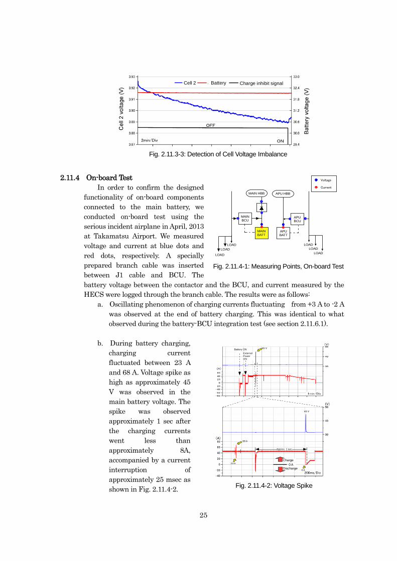
25
Fig. 2.11-6: Cell Voltage Imbalance Test
Cell 2 Battery Charge inhibit signal
2.11.4 On-board Test
In order to confirm the designed
functionality of on-board components
connected to the main battery, we
conducted on-board test using the
serious incident airplane in April, 2013
at Takamatsu Airport. We measured
voltage and current at blue dots and
red dots, respectively. A specially
prepared branch cable was inserted
between J1 cable and BCU. The
battery voltage between the contactor and the BCU, and current measured by the
HECS were logged through the branch cable. The results were as follows:
a. Oscillating phenomenon of charging currents fluctuating from +3 A to -2 A
was observed at the end of battery charging. This was identical to what
observed during the battery-BCU integration test (see section 2.11.6.1).
b. During battery charging,
charging current
fluctuated between 23 A
and 68 A. Voltage spike as
high as approximately 45
V was observed in the
main battery voltage. The
spike was observed
approximately 1 sec after
the charging currents
went less than
approximately 8A,
accompanied by a current
interruption of
approximately 25 msec as
shown in Fig. 2.11.4-2.
Fig. 2.11.3-3: Detection of Cell Voltage Imbalance
MAINBATT
MAINBCU
APUBATT
APUBCU
LOAD
MAIN HBB APU HBB
LOAD
LOAD
LOAD
LOAD
LOAD
Voltage
Current
45 V
0 A
Approx. 1 sec
45 V
68 A
23 A 0 A
Charge
Discharge
Fig. 2.11.4-2: Voltage Spike
Battery ON
External
PowerON
Fig. 2.11.4-2: Voltage Spike
Fig. 2.11.4-1: Measuring Points, On-board Test
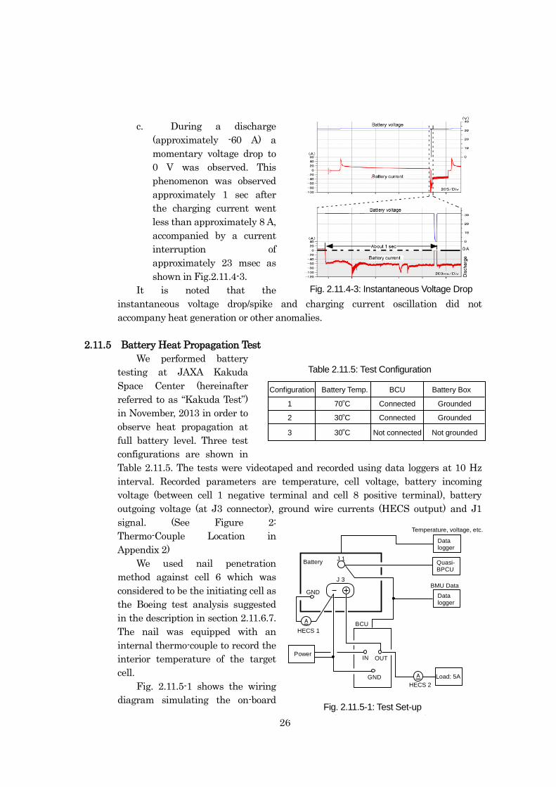
26
c. During a discharge
(approximately -60 A) a
momentary voltage drop to
0 V was observed. This
phenomenon was observed
approximately 1 sec after
the charging current went
less than approximately 8 A,
accompanied by a current
interruption of
approximately 23 msec as
shown in Fig.2.11.4-3.
It is noted that the
instantaneous voltage drop/spike and charging current oscillation did not
accompany heat generation or other anomalies.
2.11.5 Battery Heat Propagation Test
We performed battery
testing at JAXA Kakuda
Space Center (hereinafter
referred to as “Kakuda Test”)
in November, 2013 in order to
observe heat propagation at
full battery level. Three test
configurations are shown in
Table 2.11.5. The tests were videotaped and recorded using data loggers at 10 Hz
interval. Recorded parameters are temperature, cell voltage, battery incoming
voltage (between cell 1 negative terminal and cell 8 positive terminal), battery
outgoing voltage (at J3 connector), ground wire currents (HECS output) and J1
signal. (See Figure 2:
Thermo-Couple Location in
Appendix 2)
We used nail penetration
method against cell 6 which was
considered to be the initiating cell as
the Boeing test analysis suggested
in the description in section 2.11.6.7.
The nail was equipped with an
internal thermo-couple to record the
interior temperature of the target
cell.
Fig. 2.11.5-1 shows the wiring
diagram simulating the on-board
J 1
J 3
GND
Battery
IN OUT
GND
Power
BCU
HECS 2
HECS 1
Load: 5AA
Datalogger
Datalogger
BMU Data
Temperature, voltage, etc.
A
Quasi-BPCU
Fig. 2.11-10: Test Set-up
Configuration Battery Temp.
70 C
30 C
BCU Battery Box
Table 2. 11-1: Test Configuration
30 C
Connected
Not grounded
Grounded
Connected Grounded
Not connected
1
2
3
Table 2.11.5: Test Configuration
Fig. 2.11.5-1: Test Set-up
Fig. 2.11.4-3: Instantaneous Voltage Drop
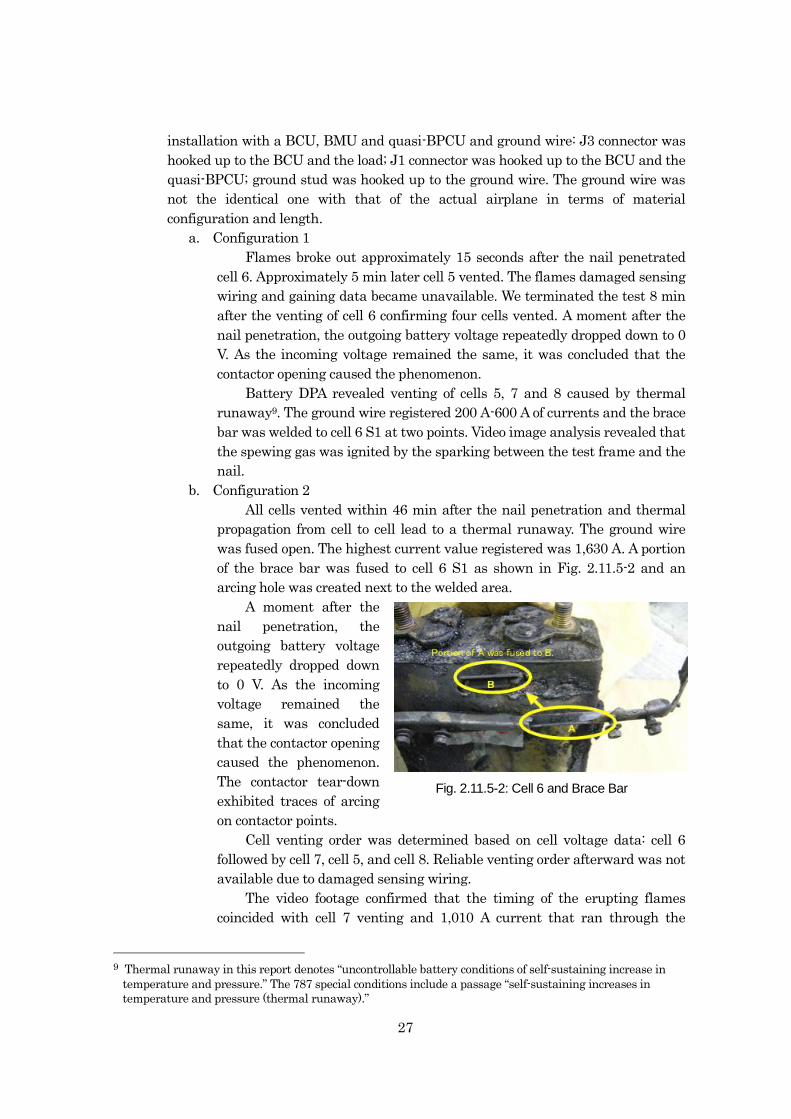
27
installation with a BCU, BMU and quasi-BPCU and ground wire: J3 connector was
hooked up to the BCU and the load; J1 connector was hooked up to the BCU and the
quasi-BPCU; ground stud was hooked up to the ground wire. The ground wire was
not the identical one with that of the actual airplane in terms of material
configuration and length.
a. Configuration 1
Flames broke out approximately 15 seconds after the nail penetrated
cell 6. Approximately 5 min later cell 5 vented. The flames damaged sensing
wiring and gaining data became unavailable. We terminated the test 8 min
after the venting of cell 6 confirming four cells vented. A moment after the
nail penetration, the outgoing battery voltage repeatedly dropped down to 0
V. As the incoming voltage remained the same, it was concluded that the
contactor opening caused the phenomenon.
Battery DPA revealed venting of cells 5, 7 and 8 caused by thermal
runaway9. The ground wire registered 200 A-600 A of currents and the brace
bar was welded to cell 6 S1 at two points. Video image analysis revealed that
the spewing gas was ignited by the sparking between the test frame and the
nail.
b. Configuration 2
All cells vented within 46 min after the nail penetration and thermal
propagation from cell to cell lead to a thermal runaway. The ground wire
was fused open. The highest current value registered was 1,630 A. A portion
of the brace bar was fused to cell 6 S1 as shown in Fig. 2.11.5-2 and an
arcing hole was created next to the welded area.
A moment after the
nail penetration, the
outgoing battery voltage
repeatedly dropped down
to 0 V. As the incoming
voltage remained the
same, it was concluded
that the contactor opening
caused the phenomenon.
The contactor tear-down
exhibited traces of arcing
on contactor points.
Cell venting order was determined based on cell voltage data: cell 6
followed by cell 7, cell 5, and cell 8. Reliable venting order afterward was not
available due to damaged sensing wiring.
The video footage confirmed that the timing of the erupting flames
coincided with cell 7 venting and 1,010 A current that ran through the
9 Thermal runaway in this report denotes “uncontrollable battery conditions of self-sustaining increase in
temperature and pressure.” The 787 special conditions include a passage “self-sustaining increases in
temperature and pressure (thermal runaway).”
Fig. 2.11.5-2: Cell 6 and Brace Bar
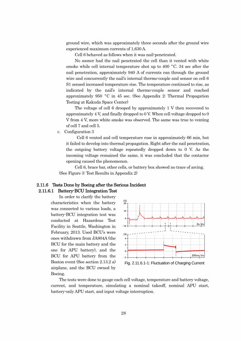
28
ground wire, which was approximately three seconds after the ground wire
experienced maximum currents of 1,630 A.
Cell 6 behaved as follows when it was nail-penetrated.
No sooner had the nail penetrated the cell than it vented with white
smoke while cell internal temperature shot up to 400 °C. 34 sec after the
nail penetration, approximately 940 A of currents ran through the ground
wire and concurrently the nail’s internal thermo-couple and sensor on cell 6
S1 sensed increased temperature rise. The temperature continued to rise, as
indicated by the nail’s internal thermo-couple sensor and reached
approximately 950 °C in 45 sec. (See Appendix 2: Thermal Propagation
Testing at Kakuda Space Center)
The voltage of cell 6 drooped by approximately 1 V then recovered to
approximately 4 V, and finally dropped to 0 V. When cell voltage dropped to 0
V from 4 V, more white smoke was observed. The same was true to venting
of cell 7 and cell 5.
c. Configuration 3
Cell 6 vented and cell temperature rose in approximately 66 min, but
it failed to develop into thermal propagation. Right after the nail penetration,
the outgoing battery voltage repeatedly dropped down to 0 V. As the
incoming voltage remained the same, it was concluded that the contactor
opening caused the phenomenon.
Cell 6, brace bar, other cells, or battery box showed no trace of arcing.
(See Figure 3: Test Results in Appendix 2)
2.11.6 Tests Done by Boeing after the Serious Incident
2.11.6.1 Battery-BCU Integration Test
In order to clarify the battery
characteristics when the battery
was connected to various loads, a
battery-BCU integration test was
conducted at Hazardous Test
Facility in Seattle, Washington in
February, 2013. Used BCU’s were
ones withdrawn from JA804A (the
BCU for the main battery and the
one for APU battery), and the
BCU for APU battery from the
Boston event (See section 2.13.2 a)
airplane, and the BCU owned by
Boeing.
The tests were done to gauge each cell voltage, temperature and battery voltage,
current, and temperature, simulating a nominal takeoff, nominal APU start,
battery-only APU start, and input voltage interruption.
Fig. 2.11.6.1-1: Fluctuation of Charging Current
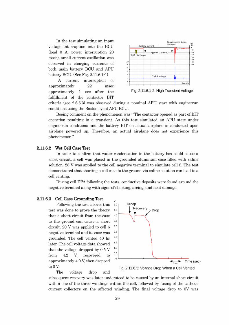
29
In the test simulating an input
voltage interruption into the BCU
(load 0 A, power interruption 20
msec), small current oscillation was
observed in charging currents of
both main battery BCU and APU
battery BCU. (See Fig. 2.11.6.1-1)
A current interruption of
approximately 22 msec
approximately 1 sec after the
fulfillment of the contactor BIT
criteria (see 2.6.5.3) was observed during a nominal APU start with engine-run
conditions using the Boston event APU BCU.
Boeing comment on the phenomenon was: “The contactor opened as part of BIT
operation resulting in a transient. As this test simulated an APU start under
engine-run conditions and the battery BIT on actual airplane is conducted upon
airplane powered up. Therefore, an actual airplane does not experience this
phenomenon.”
2.11.6.2 Wet Cell Case Test
In order to confirm that water condensation in the battery box could cause a
short circuit, a cell was placed in the grounded aluminum case filled with saline
solution. 28 V was applied to the cell negative terminal to simulate cell 8. The test
demonstrated that shorting a cell case to the ground via saline solution can lead to a
cell venting.
During cell DPA following the tests, conductive deposits were found around the
negative terminal along with signs of shorting, arcing, and heat damage.
2.11.6.3 Cell Case Grounding Test
Following the test above, this
test was done to prove the theory
that a short circuit from the case
to the ground can cause a short
circuit. 20 V was applied to cell 6
negative terminal and its case was
grounded. The cell vented 40 hr
later. The cell voltage data showed
that the voltage dropped by 0.5 V
from 4.2 V, recovered to
approximately 4.0 V, then dropped
to 0 V.
The voltage drop and
subsequent recovery was later understood to be caused by an internal short circuit
within one of the three windings within the cell, followed by fusing of the cathode
current collectors on the affected winding. The final voltage drop to 0V was
5.0
4.5
4.0
3.5
3.0
2.5
2.0
1.5
1.0
0.5
0
V
Fig. 2.11-14: Voltage Drop When a Cell Vented
5 secTime (sec)
Droop
DropRecovery
Fig. 2.11.6.3: Voltage Drop When a Cell Vented
Fig. 2.11-13: High Transient Voltage
Cell 4 voltage
Battery current
Approx. 22 msec
20A discharge
Negative amps denotedischarge.
Fig. 2.11.6.1-2: High Transient Voltage
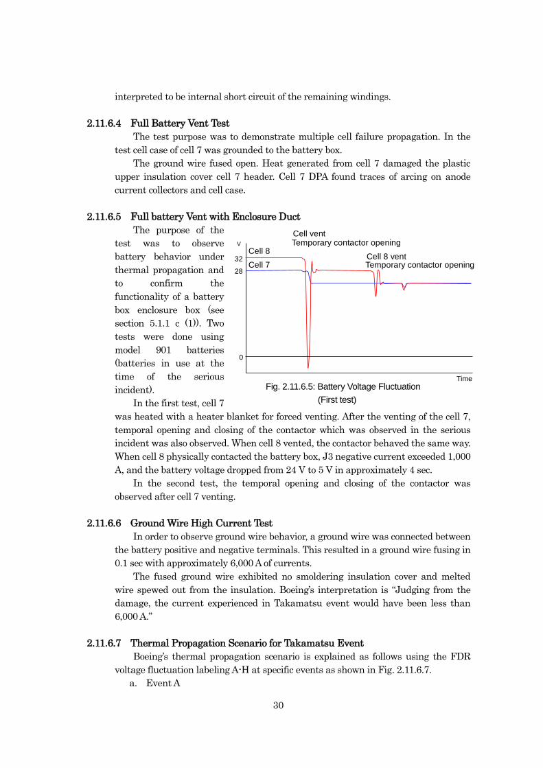
30
interpreted to be internal short circuit of the remaining windings.
2.11.6.4 Full Battery Vent Test
The test purpose was to demonstrate multiple cell failure propagation. In the
test cell case of cell 7 was grounded to the battery box.
The ground wire fused open. Heat generated from cell 7 damaged the plastic
upper insulation cover cell 7 header. Cell 7 DPA found traces of arcing on anode
current collectors and cell case.
2.11.6.5 Full battery Vent with Enclosure Duct
The purpose of the
test was to observe
battery behavior under
thermal propagation and
to confirm the
functionality of a battery
box enclosure box (see
section 5.1.1 c (1)). Two
tests were done using
model 901 batteries
(batteries in use at the
time of the serious
incident).
In the first test, cell 7
was heated with a heater blanket for forced venting. After the venting of the cell 7,
temporal opening and closing of the contactor which was observed in the serious
incident was also observed. When cell 8 vented, the contactor behaved the same way.
When cell 8 physically contacted the battery box, J3 negative current exceeded 1,000
A, and the battery voltage dropped from 24 V to 5 V in approximately 4 sec.
In the second test, the temporal opening and closing of the contactor was
observed after cell 7 venting.
2.11.6.6 Ground Wire High Current Test
In order to observe ground wire behavior, a ground wire was connected between
the battery positive and negative terminals. This resulted in a ground wire fusing in
0.1 sec with approximately 6,000 A of currents.
The fused ground wire exhibited no smoldering insulation cover and melted
wire spewed out from the insulation. Boeing’s interpretation is “Judging from the
damage, the current experienced in Takamatsu event would have been less than
6,000 A.”
2.11.6.7 Thermal Propagation Scenario for Takamatsu Event
Boeing’s thermal propagation scenario is explained as follows using the FDR
voltage fluctuation labeling A-H at specific events as shown in Fig. 2.11.6.7.
a. Event A
28
32
0
V
Fig. 2.11-16: Battery Voltage FluctuationTime
Cell ventTemporary contactor opening
Cell 8 ventCell 8
Cell 7 Temporary contactor opening
Fig. 2.11.6.5: Battery Voltage Fluctuation
(First test)
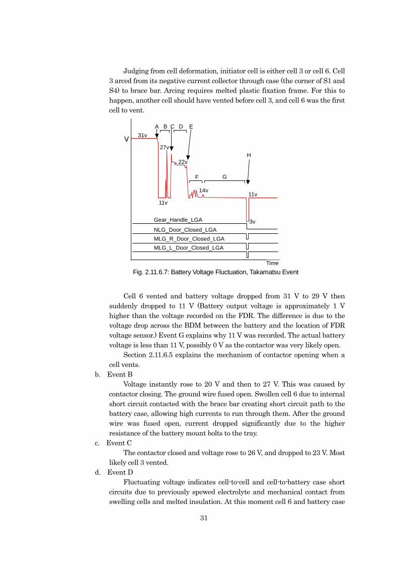
31
Judging from cell deformation, initiator cell is either cell 3 or cell 6. Cell
3 arced from its negative current collector through case (the corner of S1 and
S4) to brace bar. Arcing requires melted plastic fixation frame. For this to
happen, another cell should have vented before cell 3, and cell 6 was the first
cell to vent.
31v
27v
11v
14v
22v
3v
11v
A B C D E
F G
H
Gear_Handle_LGA
NLG_Door_Closed_LGA
MLG_R_Door_Closed_LGA
MLG_L_Door_Closed_LGA
V
Fig. 2.11-17: Battery Voltage Fluctuation During Takamatsu Event
Time
Cell 6 vented and battery voltage dropped from 31 V to 29 V then
suddenly dropped to 11 V (Battery output voltage is approximately 1 V
higher than the voltage recorded on the FDR. The difference is due to the
voltage drop across the BDM between the battery and the location of FDR
voltage sensor.) Event G explains why 11 V was recorded. The actual battery
voltage is less than 11 V, possibly 0 V as the contactor was very likely open.
Section 2.11.6.5 explains the mechanism of contactor opening when a
cell vents.
b. Event B
Voltage instantly rose to 20 V and then to 27 V. This was caused by
contactor closing. The ground wire fused open. Swollen cell 6 due to internal
short circuit contacted with the brace bar creating short circuit path to the
battery case, allowing high currents to run through them. After the ground
wire was fused open, current dropped significantly due to the higher
resistance of the battery mount bolts to the tray.
c. Event C
The contactor closed and voltage rose to 26 V, and dropped to 23 V. Most
likely cell 3 vented.
d. Event D
Fluctuating voltage indicates cell-to-cell and cell-to-battery case short
circuits due to previously spewed electrolyte and mechanical contact from
swelling cells and melted insulation. At this moment cell 6 and battery case
Fig. 2.11.6.7: Battery Voltage Fluctuation, Takamatsu Event
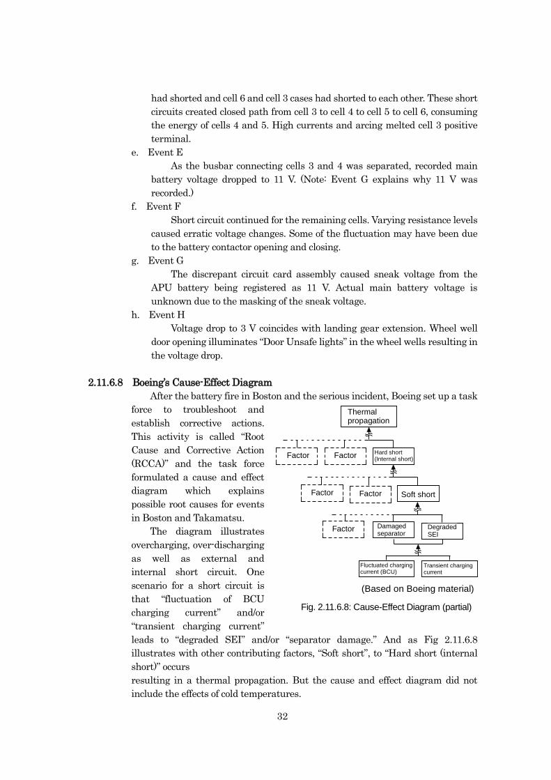
32
had shorted and cell 6 and cell 3 cases had shorted to each other. These short
circuits created closed path from cell 3 to cell 4 to cell 5 to cell 6, consuming
the energy of cells 4 and 5. High currents and arcing melted cell 3 positive
terminal.
e. Event E
As the busbar connecting cells 3 and 4 was separated, recorded main
battery voltage dropped to 11 V. (Note: Event G explains why 11 V was
recorded.)
f. Event F
Short circuit continued for the remaining cells. Varying resistance levels
caused erratic voltage changes. Some of the fluctuation may have been due
to the battery contactor opening and closing.
g. Event G
The discrepant circuit card assembly caused sneak voltage from the
APU battery being registered as 11 V. Actual main battery voltage is
unknown due to the masking of the sneak voltage.
h. Event H
Voltage drop to 3 V coincides with landing gear extension. Wheel well
door opening illuminates “Door Unsafe lights” in the wheel wells resulting in
the voltage drop.
2.11.6.8 Boeing’s Cause-Effect Diagram
After the battery fire in Boston and the serious incident, Boeing set up a task
force to troubleshoot and
establish corrective actions.
This activity is called “Root
Cause and Corrective Action
(RCCA)” and the task force
formulated a cause and effect
diagram which explains
possible root causes for events
in Boston and Takamatsu.
The diagram illustrates
overcharging, over-discharging
as well as external and
internal short circuit. One
scenario for a short circuit is
that “fluctuation of BCU
charging current” and/or
“transient charging current”
leads to “degraded SEI” and/or “separator damage.” And as Fig 2.11.6.8
illustrates with other contributing factors, “Soft short”, to “Hard short (internal
short)” occurs
resulting in a thermal propagation. But the cause and effect diagram did not
include the effects of cold temperatures.
Fluctuated chargingcurrent (BCU)
Transient chargingcurrent
Factor
Thermalpropagation
Factor
Factor
FactorFactor
Hard short(Internal short)
Soft short
Damagedseparator
DegradedSEI
(Based on Boeing material)
Fig. 2.11.6.8: Cause-Effect Diagram (partial)
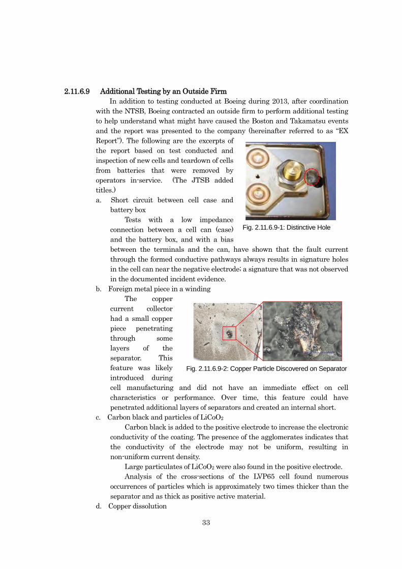
33
2.11.6.9 Additional Testing by an Outside Firm
In addition to testing conducted at Boeing during 2013, after coordination
with the NTSB, Boeing contracted an outside firm to perform additional testing
to help understand what might have caused the Boston and Takamatsu events
and the report was presented to the company (hereinafter referred to as “EX
Report”). The following are the excerpts of
the report based on test conducted and
inspection of new cells and teardown of cells
from batteries that were removed by
operators in-service. (The JTSB added
titles.)
a. Short circuit between cell case and
battery box
Tests with a low impedance
connection between a cell can (case)
and the battery box, and with a bias
between the terminals and the can, have shown that the fault current
through the formed conductive pathways always results in signature holes
in the cell can near the negative electrode; a signature that was not observed
in the documented incident evidence.
b. Foreign metal piece in a winding
The copper
current collector
had a small copper
piece penetrating
through some
layers of the
separator. This
feature was likely
introduced during
cell manufacturing and did not have an immediate effect on cell
characteristics or performance. Over time, this feature could have
penetrated additional layers of separators and created an internal short.
c. Carbon black and particles of LiCoO2
Carbon black is added to the positive electrode to increase the electronic
conductivity of the coating. The presence of the agglomerates indicates that
the conductivity of the electrode may not be uniform, resulting in
non-uniform current density.
Large particulates of LiCoO2 were also found in the positive electrode.
Analysis of the cross-sections of the LVP65 cell found numerous
occurrences of particles which is approximately two times thicker than the
separator and as thick as positive active material.
d. Copper dissolution
Fig. 2.11-19: Distinctive Hole
Fig. 2.11.6.9-1: Distinctive Hole
Fig. 2.11-20: Copper Particle Discovered on SeparatorFig. 2.11.6.9-2: Copper Particle Discovered on Separator
Fig. 2.11.6.9-1: Distinctive Hole
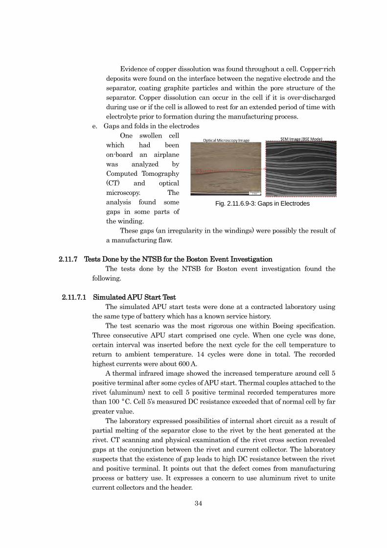
34
Evidence of copper dissolution was found throughout a cell. Copper-rich
deposits were found on the interface between the negative electrode and the
separator, coating graphite particles and within the pore structure of the
separator. Copper dissolution can occur in the cell if it is over-discharged
during use or if the cell is allowed to rest for an extended period of time with
electrolyte prior to formation during the manufacturing process.
e. Gaps and folds in the electrodes
One swollen cell
which had been
on-board an airplane
was analyzed by
Computed Tomography
(CT) and optical
microscopy. The
analysis found some
gaps in some parts of
the winding.
These gaps (an irregularity in the windings) were possibly the result of
a manufacturing flaw.
2.11.7 Tests Done by the NTSB for the Boston Event Investigation
The tests done by the NTSB for Boston event investigation found the
following.
2.11.7.1 Simulated APU Start Test
The simulated APU start tests were done at a contracted laboratory using
the same type of battery which has a known service history.
The test scenario was the most rigorous one within Boeing specification.
Three consecutive APU start comprised one cycle. When one cycle was done,
certain interval was inserted before the next cycle for the cell temperature to
return to ambient temperature. 14 cycles were done in total. The recorded
highest currents were about 600 A.
A thermal infrared image showed the increased temperature around cell 5
positive terminal after some cycles of APU start. Thermal couples attached to the
rivet (aluminum) next to cell 5 positive terminal recorded temperatures more
than 100 °C. Cell 5’s measured DC resistance exceeded that of normal cell by far
greater value.
The laboratory expressed possibilities of internal short circuit as a result of
partial melting of the separator close to the rivet by the heat generated at the
rivet. CT scanning and physical examination of the rivet cross section revealed
gaps at the conjunction between the rivet and current collector. The laboratory
suspects that the existence of gap leads to high DC resistance between the rivet
and positive terminal. It points out that the defect comes from manufacturing
process or battery use. It expresses a concern to use aluminum rivet to unite
current collectors and the header.
Fig.2.11-21: Gaps in ElectrodesFig. 2.11.6.9-3: Gaps in Electrodes
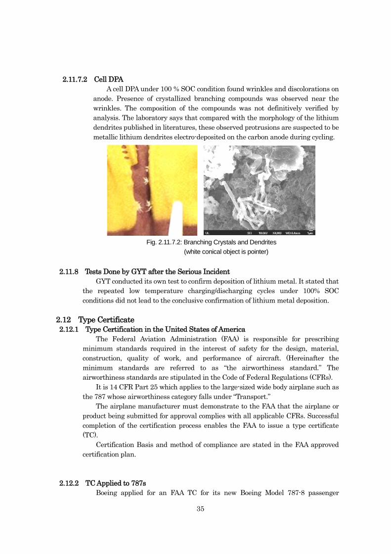
35
2.11.7.2 Cell DPA
A cell DPA under 100 % SOC condition found wrinkles and discolorations on
anode. Presence of crystallized branching compounds was observed near the
wrinkles. The composition of the compounds was not definitively verified by
analysis. The laboratory says that compared with the morphology of the lithium
dendrites published in literatures, these observed protrusions are suspected to be
metallic lithium dendrites electro-deposited on the carbon anode during cycling.
2.11.8 Tests Done by GYT after the Serious Incident
GYT conducted its own test to confirm deposition of lithium metal. It stated that
the repeated low temperature charging/discharging cycles under 100% SOC
conditions did not lead to the conclusive confirmation of lithium metal deposition.
2.12 Type Certificate
2.12.1 Type Certification in the United States of America
The Federal Aviation Administration (FAA) is responsible for prescribing
minimum standards required in the interest of safety for the design, material,
construction, quality of work, and performance of aircraft. (Hereinafter the
minimum standards are referred to as “the airworthiness standard.” The
airworthiness standards are stipulated in the Code of Federal Regulations (CFRs).
It is 14 CFR Part 25 which applies to the large-sized wide body airplane such as
the 787 whose airworthiness category falls under “Transport.”
The airplane manufacturer must demonstrate to the FAA that the airplane or
product being submitted for approval complies with all applicable CFRs. Successful
completion of the certification process enables the FAA to issue a type certificate
(TC).
Certification Basis and method of compliance are stated in the FAA approved
certification plan.
2.12.2 TC Applied to 787s
Boeing applied for an FAA TC for its new Boeing Model 787-8 passenger
Fig. 2.11.7.2: Branching Crystals and Dendrites
(white conical object is pointer)
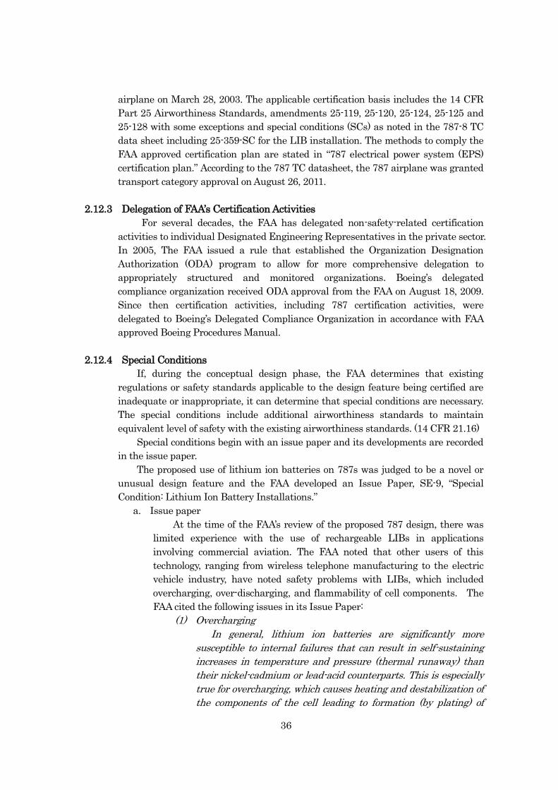
36
airplane on March 28, 2003. The applicable certification basis includes the 14 CFR
Part 25 Airworthiness Standards, amendments 25-119, 25-120, 25-124, 25-125 and
25-128 with some exceptions and special conditions (SCs) as noted in the 787-8 TC
data sheet including 25-359-SC for the LIB installation. The methods to comply the
FAA approved certification plan are stated in “787 electrical power system (EPS)
certification plan.” According to the 787 TC datasheet, the 787 airplane was granted
transport category approval on August 26, 2011.
2.12.3 Delegation of FAA’s Certification Activities
For several decades, the FAA has delegated non-safety-related certification
activities to individual Designated Engineering Representatives in the private sector.
In 2005, The FAA issued a rule that established the Organization Designation
Authorization (ODA) program to allow for more comprehensive delegation to
appropriately structured and monitored organizations. Boeing’s delegated
compliance organization received ODA approval from the FAA on August 18, 2009.
Since then certification activities, including 787 certification activities, were
delegated to Boeing’s Delegated Compliance Organization in accordance with FAA
approved Boeing Procedures Manual.
2.12.4 Special Conditions
If, during the conceptual design phase, the FAA determines that existing
regulations or safety standards applicable to the design feature being certified are
inadequate or inappropriate, it can determine that special conditions are necessary.
The special conditions include additional airworthiness standards to maintain
equivalent level of safety with the existing airworthiness standards. (14 CFR 21.16)
Special conditions begin with an issue paper and its developments are recorded
in the issue paper.
The proposed use of lithium ion batteries on 787s was judged to be a novel or
unusual design feature and the FAA developed an Issue Paper, SE-9, “Special
Condition: Lithium Ion Battery Installations.”
a. Issue paper
At the time of the FAA’s review of the proposed 787 design, there was
limited experience with the use of rechargeable LIBs in applications
involving commercial aviation. The FAA noted that other users of this
technology, ranging from wireless telephone manufacturing to the electric
vehicle industry, have noted safety problems with LIBs, which included
overcharging, over-discharging, and flammability of cell components. The
FAA cited the following issues in its Issue Paper:
(1) Overcharging
In general, lithium ion batteries are significantly more
susceptible to internal failures that can result in self-sustaining
increases in temperature and pressure (thermal runaway) than
their nickel-cadmium or lead-acid counterparts. This is especially
true for overcharging, which causes heating and destabilization of
the components of the cell leading to formation (by plating) of
37
highly unstable metallic lithium. The metallic lithium can ignite,
resulting in a self-sustaining fire or explosion. Finally, the severity
of thermal runaway from overcharging increases with increasing
battery capacity, because of the higher amount of electrolytes in
large batteries.
(2) Over-Discharging
Discharge of some types of lithium ion batteries beyond a
certain voltage (typically 2.4 volts) can cause corrosion of the
electrodes of the cell, resulting in loss of battery capacity that
cannot be reversed by recharging. This loss of capacity may not be
detected by the simple voltage measurements commonly available
to flight crews as a means of checking battery status. This is a
problem shared with nickel-cadmium batteries.
(3) Flammability of Cell Components
Unlike nickel-cadmium and lead-acid batteries, some types of
lithium ion batteries use liquid electrolytes that are flammable.
The electrolytes can serve as a source of fuel for an external fire, if
there is a breach of the battery container.
b. Special conditions (25-359-SC)
After the review of the issue paper, the FAA issued nine special
conditions for the 787 LIB installation (25-359-SC) to mitigate safety
problems caused by overcharging, over-discharging, and flammability of cell
components on September 28, 2007. The special condition became effective
on November 13, 2007 as part of the type certification basis for the Boeing
Model 787-8 airplane.
The special conditions for the 787 LIB were the same as the ones for
LIBs for emergency lights installed on Airbus A380, which were issued and
became effective on November 30, 2006. The special conditions for the
Airbus A380 and 787 LIB were the same even though the battery
configuration and capacity on each aircraft are different.
25-359-SC states:
In lieu of the requirements of 14 CFR 25.1353(c) (1) through (c) (4), the
following special conditions apply. Lithium ion batteries on the Boeing
Model 787-8 airplane must be designed and installed as follows:
(1) Safe cell temperatures and pressures must be maintained during
any foreseeable charging or discharging condition and during any
failure of the charging or battery monitoring system not shown to
be extremely remote. The lithium ion battery installation must
preclude explosion in the event of those failures.
(2) Design of the lithium ion batteries must preclude the occurrence of
self-sustaining, uncontrolled increases in temperature or pressure.
(3) No explosive or toxic gases emitted by any lithium ion battery in
normal operation, or as the result of any failure of the battery
charging system, monitoring system, or battery installation not
shown to be extremely remote, may accumulate in hazardous
38
quantities within the airplane.
(4) Installations of lithium ion batteries must meet the requirements of
14 CFR 25.863(a) through (d).
(5) No corrosive fluids or gases that may escape from any lithium ion
battery may damage surrounding structure or any adjacent
systems, equipment, or electrical wiring of the airplane in such a
way as to cause a major or more severe failure condition, in
accordance with 14 CFR 25.1309(b) and applicable regulatory
guidance.
(6) Each lithium ion battery installation must have provisions to
prevent any hazardous effect on structure or essential systems
caused by the maximum amount of heat the battery can generate
during a short circuit of the battery or of its individual cells.
(7) Lithium ion battery installations must have a system to control the
charging rate of the battery automatically, so as to prevent battery
overheating or overcharging, and,
(i) A battery temperature sensing and over-temperature warning
system with a means for automatically disconnecting the
battery from its charging source in the event of an
over-temperature condition, or,
(ii) A battery failure sensing and warning system with a means for
automatically disconnecting the battery from its charging
source in the event of battery failure.
(8) Any lithium ion battery installation whose function is required for
safe operation of the airplane must incorporate a monitoring and
warning feature that will provide an indication to the appropriate
flight crewmembers whenever the state-of-charge of the batteries
has fallen below levels considered acceptable for dispatch of the
airplane.
(9) The Instructions for Continued Airworthiness required by 14 CFR
25.1529 must contain maintenance requirements for
measurements of battery capacity at appropriate intervals to
ensure that batteries whose function is required for safe operation
of the airplane will perform their intended function as long as the
battery is installed in the airplane. The Instructions for Continued
Airworthiness must also contain procedures for the maintenance
of lithium-ion batteries in spares storage to prevent the
replacement of batteries whose function is required for safe
operation of the airplane with batteries that have experienced
degraded charge retention ability or other damage due to
prolonged storage at a low state of charge.
Note: These special conditions are not intended to replace 14 CFR
25.1353(c) in the certification basis of the Boeing 787-8 airplane.
These special conditions apply only to lithium ion batteries and
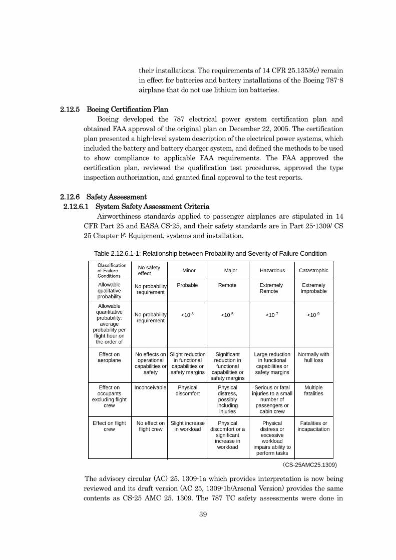
39
their installations. The requirements of 14 CFR 25.1353(c) remain
in effect for batteries and battery installations of the Boeing 787-8
airplane that do not use lithium ion batteries.
2.12.5 Boeing Certification Plan
Boeing developed the 787 electrical power system certification plan and
obtained FAA approval of the original plan on December 22, 2005. The certification
plan presented a high-level system description of the electrical power systems, which
included the battery and battery charger system, and defined the methods to be used
to show compliance to applicable FAA requirements. The FAA approved the
certification plan, reviewed the qualification test procedures, approved the type
inspection authorization, and granted final approval to the test reports.
2.12.6 Safety Assessment
2.12.6.1 System Safety Assessment Criteria
Airworthiness standards applied to passenger airplanes are stipulated in 14
CFR Part 25 and EASA CS-25, and their safety standards are in Part 25-1309/ CS
25 Chapter F: Equipment, systems and installation.
The advisory circular (AC) 25. 1309-1a which provides interpretation is now being
reviewed and its draft version (AC 25, 1309-1b/Arsenal Version) provides the same
contents as CS-25 AMC 25. 1309. The 787 TC safety assessments were done in
Classificationof FailureConditions
Minor Major Hazardous Catastrophic
ExtremelyImprobable
ExtremelyRemote
RemoteProbable
<10-3 <10-5 <10-7 <10-9
Table 2.12-1: Relationship Between Probability and Severity of Failure Condition
(CS-25AMC25.1309)
No safetyeffect
Allowablequalitativeprobability
No probabilityrequirement
No probabilityrequirement
Allowablequantitativeprobability:
averageprobability perflight hour onthe order of
Effect onaeroplane
No effects onoperational
capabilities orsafety
Slight reductionin functional
capabilities orsafety margins
Significantreduction infunctional
capabilities orsafety margins
Large reductionin functional
capabilities orsafety margins
Normally withhull loss
Effect onoccupants
excluding flightcrew
Physicaldiscomfort
Physicaldistress,possiblyincludinginjuries
Serious or fatalinjuries to a small
number ofpassengers or
cabin crew
Multiplefatalities
Inconceivable
Effect on flightcrew
No effect onflight crew
Slight increasein workload
Physicaldiscomfort or a
significantincrease inworkload
Physicaldistress orexcessiveworkload
impairs ability toperform tasks
Fatalities orincapacitation
Table 2.12.6.1-1: Relationship between Probability and Severity of Failure Condition
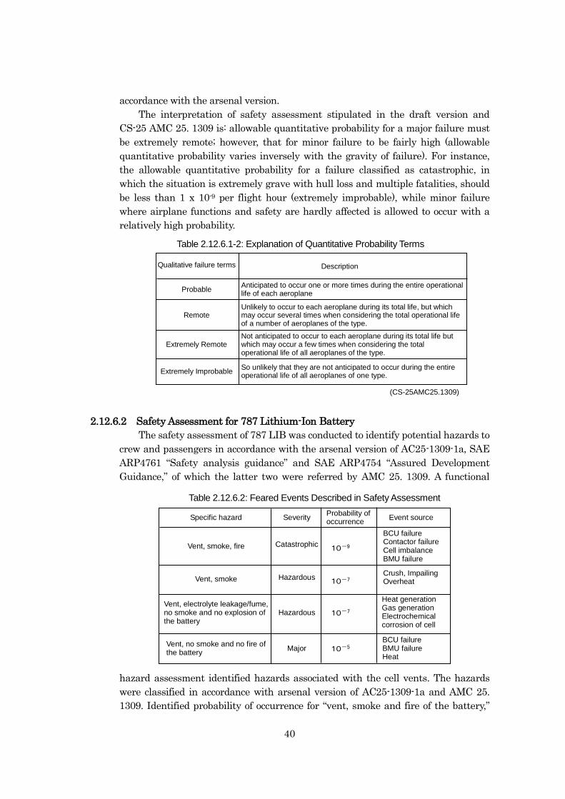
40
accordance with the arsenal version.
The interpretation of safety assessment stipulated in the draft version and
CS-25 AMC 25. 1309 is: allowable quantitative probability for a major failure must
be extremely remote; however, that for minor failure to be fairly high (allowable
quantitative probability varies inversely with the gravity of failure). For instance,
the allowable quantitative probability for a failure classified as catastrophic, in
which the situation is extremely grave with hull loss and multiple fatalities, should
be less than 1 x 10⁻⁹ per flight hour (extremely improbable), while minor failure
where airplane functions and safety are hardly affected is allowed to occur with a
relatively high probability.
2.12.6.2 Safety Assessment for 787 Lithium-Ion Battery
The safety assessment of 787 LIB was conducted to identify potential hazards to
crew and passengers in accordance with the arsenal version of AC25-1309-1a, SAE
ARP4761 “Safety analysis guidance” and SAE ARP4754 “Assured Development
Guidance,” of which the latter two were referred by AMC 25. 1309. A functional
hazard assessment identified hazards associated with the cell vents. The hazards
were classified in accordance with arsenal version of AC25-1309-1a and AMC 25.
1309. Identified probability of occurrence for “vent, smoke and fire of the battery,”
Probable
Remote
Extremely Remote
Extremely Improbable
(CS-25AMC25.1309)
Fig. 2.12-2: Explanation of Qualitative Probability Terms
Qualitative failure terms Description
Anticipated to occur one or more times during the entire operationallife of each aeroplane
Unlikely to occur to each aeroplane during its total life, but whichmay occur several times when considering the total operational lifeof a number of aeroplanes of the type.
Not anticipated to occur to each aeroplane during its total life butwhich may occur a few times when considering the totaloperational life of all aeroplanes of the type.
So unlikely that they are not anticipated to occur during the entireoperational life of all aeroplanes of one type.
10-9Catastrophic
10-5
10-7
10-7Hazardous
Major
Hazardous
Fig. 2.12-3: Feared Events Described in Safety Assessment
Specific hazardProbability ofoccurrence
Event sourceSeverity
Vent, smoke, fire
Vent, smoke
Vent, electrolyte leakage/fume,no smoke and no explosion ofthe battery
Vent, no smoke and no fire ofthe battery
BCU failureContactor failureCell imbalanceBMU failure
Crush, ImpailingOverheat
BCU failureBMU failureHeat
Heat generationGas generationElectrochemicalcorrosion of cell
Table 2.12.6.2: Feared Events Described in Safety Assessment
Table 2.12.6.1-2: Explanation of Quantitative Probability Terms
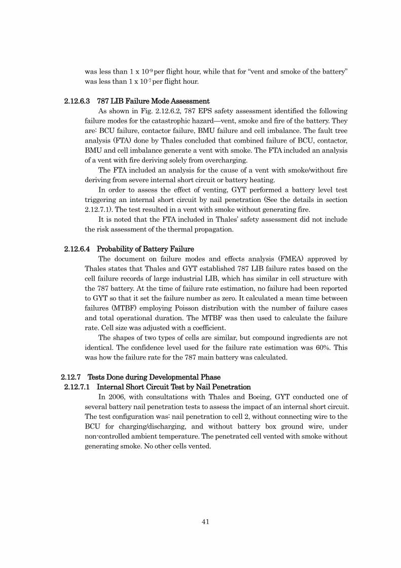
41
was less than 1 x 10⁻⁹ per flight hour, while that for “vent and smoke of the battery”
was less than 1 x 10⁻⁷ per flight hour.
2.12.6.3 787 LIB Failure Mode Assessment
As shown in Fig. 2.12.6.2, 787 EPS safety assessment identified the following
failure modes for the catastrophic hazard—vent, smoke and fire of the battery. They
are: BCU failure, contactor failure, BMU failure and cell imbalance. The fault tree
analysis (FTA) done by Thales concluded that combined failure of BCU, contactor,
BMU and cell imbalance generate a vent with smoke. The FTA included an analysis
of a vent with fire deriving solely from overcharging.
The FTA included an analysis for the cause of a vent with smoke/without fire
deriving from severe internal short circuit or battery heating.
In order to assess the effect of venting, GYT performed a battery level test
triggering an internal short circuit by nail penetration (See the details in section
2.12.7.1). The test resulted in a vent with smoke without generating fire.
It is noted that the FTA included in Thales’ safety assessment did not include
the risk assessment of the thermal propagation.
2.12.6.4 Probability of Battery Failure
The document on failure modes and effects analysis (FMEA) approved by
Thales states that Thales and GYT established 787 LIB failure rates based on the
cell failure records of large industrial LIB, which has similar in cell structure with
the 787 battery. At the time of failure rate estimation, no failure had been reported
to GYT so that it set the failure number as zero. It calculated a mean time between
failures (MTBF) employing Poisson distribution with the number of failure cases
and total operational duration. The MTBF was then used to calculate the failure
rate. Cell size was adjusted with a coefficient.
The shapes of two types of cells are similar, but compound ingredients are not
identical. The confidence level used for the failure rate estimation was 60%. This
was how the failure rate for the 787 main battery was calculated.
2.12.7 Tests Done during Developmental Phase
2.12.7.1 Internal Short Circuit Test by Nail Penetration
In 2006, with consultations with Thales and Boeing, GYT conducted one of
several battery nail penetration tests to assess the impact of an internal short circuit.
The test configuration was: nail penetration to cell 2, without connecting wire to the
BCU for charging/discharging, and without battery box ground wire, under
non-controlled ambient temperature. The penetrated cell vented with smoke without
generating smoke. No other cells vented.
42
This test was a part of engineering tests and the test result was presented to the
FAA at a briefing when Boeing was finalizing the LIB technical requirements. As a
result, the internal short circuit test was not included in the TC engineering test.
2.12.7.2 Climatic Tests
In 2010 GYT conducted climatic tests as part of TC engineering tests. The tests
were conducted in accordance with the procedures approved by Thales and Boeing.
a. Low temperature test
In the test, a battery temperature was varied from in-flight outside
temperature to battery operational lower limit and BMU function was
checked accompanied by discharging at tens of amps and charging.
The test revealed no anomalies to battery voltage, electric insulation
resistance, temperature sensor, contactor, or impedance. No leakage of
electrolyte was observed.
b. Tests at Varied Temperature
In the test, couples of cycles of tests were conducted. In each cycle a
subject battery was exposed to operational temperature range. The battery
discharging/charging behaviors, and BMU functions across this
temperature range were monitored.
The test revealed no anomalies.
2.12.7.3 External Short Circuit Test
In 2010, GYT conducted external short circuit test (low and high
resistance). The tests were conducted in accordance with the procedures
approved by Thales and Boeing.
a. Low resistance external short circuit test
A fully charged battery was warmed to its upper limit of operational
temperature. The external short circuit path was created using low
resistance. Power cables used were elongated actual power cables.
The test revealed that the short circuit allowed several thousand
amps of currents to run for an extremely short time after the shorting and
the current dropped to 0 A. The contactor was expected to open, but the data
analysis concluded that the contactor remained shut and the current
dropped to 0 A as the current collectors fused open. The post-test battery
temperature was within safety range. No electrolyte leakage, smoke or fire
was observed.
b. High resistance external short circuit test
Fig. 2.12.7.1: Observed Smoke
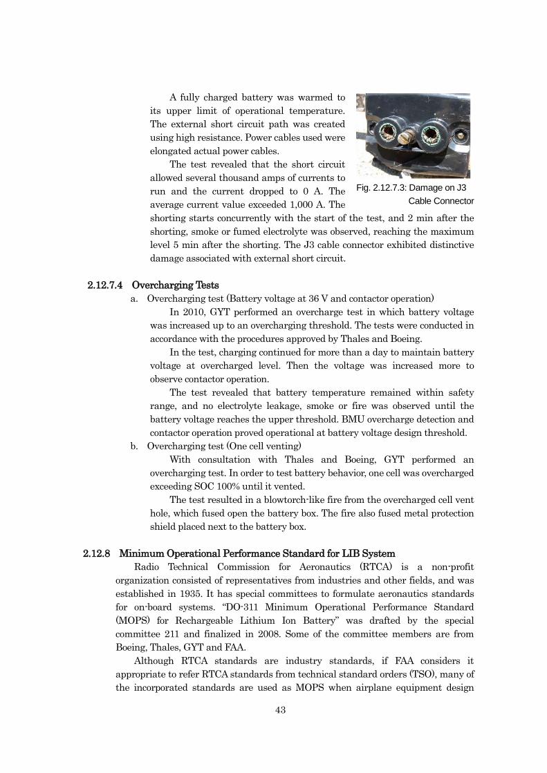
43
A fully charged battery was warmed to
its upper limit of operational temperature.
The external short circuit path was created
using high resistance. Power cables used were
elongated actual power cables.
The test revealed that the short circuit
allowed several thousand amps of currents to
run and the current dropped to 0 A. The
average current value exceeded 1,000 A. The
shorting starts concurrently with the start of the test, and 2 min after the
shorting, smoke or fumed electrolyte was observed, reaching the maximum
level 5 min after the shorting. The J3 cable connector exhibited distinctive
damage associated with external short circuit.
2.12.7.4 Overcharging Tests
a. Overcharging test (Battery voltage at 36 V and contactor operation)
In 2010, GYT performed an overcharge test in which battery voltage
was increased up to an overcharging threshold. The tests were conducted in
accordance with the procedures approved by Thales and Boeing.
In the test, charging continued for more than a day to maintain battery
voltage at overcharged level. Then the voltage was increased more to
observe contactor operation.
The test revealed that battery temperature remained within safety
range, and no electrolyte leakage, smoke or fire was observed until the
battery voltage reaches the upper threshold. BMU overcharge detection and
contactor operation proved operational at battery voltage design threshold.
b. Overcharging test (One cell venting)
With consultation with Thales and Boeing, GYT performed an
overcharging test. In order to test battery behavior, one cell was overcharged
exceeding SOC 100% until it vented.
The test resulted in a blowtorch-like fire from the overcharged cell vent
hole, which fused open the battery box. The fire also fused metal protection
shield placed next to the battery box.
2.12.8 Minimum Operational Performance Standard for LIB System
Radio Technical Commission for Aeronautics (RTCA) is a non-profit
organization consisted of representatives from industries and other fields, and was
established in 1935. It has special committees to formulate aeronautics standards
for on-board systems. “DO-311 Minimum Operational Performance Standard
(MOPS) for Rechargeable Lithium Ion Battery” was drafted by the special
committee 211 and finalized in 2008. Some of the committee members are from
Boeing, Thales, GYT and FAA.
Although RTCA standards are industry standards, if FAA considers it
appropriate to refer RTCA standards from technical standard orders (TSO), many of
the incorporated standards are used as MOPS when airplane equipment design
Fig. 2.12.7.3: Damage on J3
Cable Connector
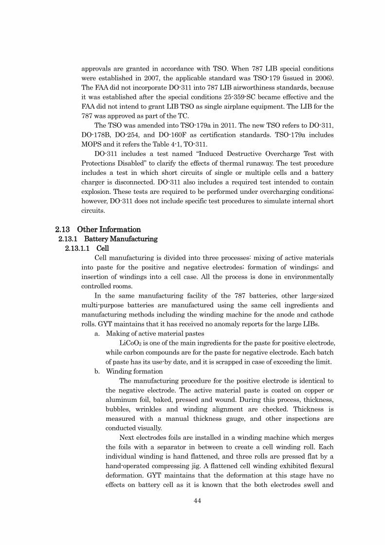
44
approvals are granted in accordance with TSO. When 787 LIB special conditions
were established in 2007, the applicable standard was TSO-179 (issued in 2006).
The FAA did not incorporate DO-311 into 787 LIB airworthiness standards, because
it was established after the special conditions 25-359-SC became effective and the
FAA did not intend to grant LIB TSO as single airplane equipment. The LIB for the
787 was approved as part of the TC.
The TSO was amended into TSO-179a in 2011. The new TSO refers to DO-311,
DO-178B, DO-254, and DO-160F as certification standards. TSO-179a includes
MOPS and it refers the Table 4-1, TO-311.
DO-311 includes a test named “Induced Destructive Overcharge Test with
Protections Disabled” to clarify the effects of thermal runaway. The test procedure
includes a test in which short circuits of single or multiple cells and a battery
charger is disconnected. DO-311 also includes a required test intended to contain
explosion. These tests are required to be performed under overcharging conditions;
however, DO-311 does not include specific test procedures to simulate internal short
circuits.
2.13 Other Information
2.13.1 Battery Manufacturing
2.13.1.1 Cell
Cell manufacturing is divided into three processes: mixing of active materials
into paste for the positive and negative electrodes; formation of windings; and
insertion of windings into a cell case. All the process is done in environmentally
controlled rooms.
In the same manufacturing facility of the 787 batteries, other large-sized
multi-purpose batteries are manufactured using the same cell ingredients and
manufacturing methods including the winding machine for the anode and cathode
rolls. GYT maintains that it has received no anomaly reports for the large LIBs.
a. Making of active material pastes
LiCoO2 is one of the main ingredients for the paste for positive electrode,
while carbon compounds are for the paste for negative electrode. Each batch
of paste has its use-by date, and it is scrapped in case of exceeding the limit.
b. Winding formation
The manufacturing procedure for the positive electrode is identical to
the negative electrode. The active material paste is coated on copper or
aluminum foil, baked, pressed and wound. During this process, thickness,
bubbles, wrinkles and winding alignment are checked. Thickness is
measured with a manual thickness gauge, and other inspections are
conducted visually.
Next electrodes foils are installed in a winding machine which merges
the foils with a separator in between to create a cell winding roll. Each
individual winding is hand flattened, and three rolls are pressed flat by a
hand-operated compressing jig. A flattened cell winding exhibited flexural
deformation. GYT maintains that the deformation at this stage have no
effects on battery cell as it is known that the both electrodes swell and
45
shrink during charging and discharging, respectively.
c. Cell assembly
Current collectors are hand assembled and clipped to the copper and
aluminum foil on each side of a compressed roll. This assembly is then
ultrasonically-welded to each corresponding electrode. The welded bundle is
then wrapped with insulating film and heat-resistant tape, and inserted into
a cell case. The header and the case is tungsten-inert-gas (TIG)-welded and
be subjected to air leak test.
The cell is then fed with electrolyte through a small hole. The hole is
plugged with a spherical metal ball and resistance-welded. The cell goes
through a number of inspections: weight, leak, AC/DC resistance, capacity,
internal soft short, CT scanning.
2.13.1.2 Battery Assembly
Fig. 2.13.1.2 illustrates internal parts used for a battery construction. All
assembly is done manually. Lower fixation frames are placed on the battery box floor.
Cells are placed on them facing each safety valve oriented to the box side wall.
Spacers are inserted between the cells. Top fixation frames are placed on the cells
and bolted to the brace bar. Busbars, thermo-sensors are connected to the cells. The
BMU, contactor, and HECS are installed in the box to finalize the battery
construction. The battery goes through AC/DC resistance check and ATP.
2.13.1.3 Foreign Object Damage Prevention Measures
The following foreign object damage (FOD) prevention measures are taken by
GYT and it maintains no possibility of contamination during manufacturing.
a. Manufacturing process
The cell manufacturing facility is an environmentally controlled clean
room. It is mandatory to wear head cover, electro static dissipative shoes and
other garments to maintain the cleanness. When a person goes into the
facility, he/she has to go through double doors and air curtain to be dusted
Fig. 2.13.1.1: Cell Manufacturing
Fig. 2.13.1.2: Battery Assembly
46
off. At the entrance floor, one steps on sticky sheet to remove dust from the
soles. The facility’s interior air pressure is higher than outside to push back
small particles suspended in the air. The air filters installed in the intake air
fans are replaced periodically.
Cell manufacturing facility is divided into active material mixing room
and cell assembly room. Both rooms have almost the same level of FOD
prevention measures. Cell assembly personnel are required to wear gloves
and surgical masc.
The powdery cell active materials are weighed after reception and put
into the mixer to produce paste. There is no specific procedure to filter out
foreign objects.
There is no possibility of foreign object contamination deriving from
cutting dust as no cutting procedure is involved in the cell manufacturing
process.
Possible foreign object contamination can occur when active materials
are coated on foils and current collectors are ultrasonically-welded to
windings. Magnetic filters are used to catch foreign ferrous metallic objects
during the coating process. A vacuum cleaner is attached next to the
welding machine to remove debris generated during the ultrasonic welding.
b. Inspection during and after the manufacturing
Before a cell is fed with electrolyte, voltage is applied between the
positive and negative terminals to check for internal short circuit.
After the cell manufacturing, it is subjected to soft short test and CT
scanning.
2.13.2 Similar Battery Events
a. Boston event
At 10:21 on January 7, 2013 (US. Eastern Standard Time), an APU
battery of a 787 parked at a gate at General Edward Lawrence Logan
International Airport, Boston generated smoke. A mechanic on board the
airplane saw two small vertical flames on the connector when he opened the
aft EE bay.
The event is now under investigation by the NTSB10.
b. Narita event
On January 14, 2014, a mechanic on board a 787 parked at Narita
International Airport for preparation for the next flight saw smoke flowing
outboard and confirmed a message of failed main battery and BCU on the
EICAS screen. The investigation found that cell 5 had vented and the
remaining seven cells were still producing a normal voltage (approximately
4 volts). In 2013, all 787 airplanes were modified to house the main and APU
batteries in metal enclosures ducted to the outside of the airplane. In this
event, the enclosure box prevented any electrolyte from escaping into the
cabin and expelled it overboard.
10 For the detail of the investigation, visit the NTSB website at http://www.ntsb.gov.
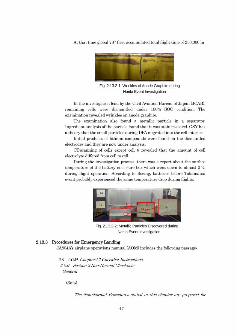
47
At that time global 787 fleet accumulated total flight time of 250,000 hr.
In the investigation lead by the Civil Aviation Bureau of Japan (JCAB),
remaining cells were dismantled under 100% SOC condition. The
examination revealed wrinkles on anode graphite.
The examination also found a metallic particle in a separator.
Ingredient analysis of the particle found that it was stainless steel. GSY has
a theory that the small particles during DPA migrated into the cell interior.
Initial products of lithium compounds were found on the dismantled
electrodes and they are now under analysis.
CT-scanning of cells except cell 6 revealed that the amount of cell
electrolyte differed from cell to cell.
During the investigation process, there was a report about the surface
temperature of the battery enclosure box which went down to almost 0°C
during flight operation. According to Boeing, batteries before Takamatsu
event probably experienced the same temperature drop during flights.
2.13.3 Procedures for Emergency Landing
JA804A’s airplane operations manual (AOM) includes the following passage:
2.0 AOM, Chapter CI Checklist Instructions
2.0.0 Section 2 Non-Normal Checklists
General
(Snip)
The Non-Normal Procedures stated in this chapter are prepared for
Fig. 2.13.2-1: Wrinkles of Anode Graphite during
Narita Event Investigation
Fig. 2.13.2-2: Metallic Particles Discovered during
Narita Event Investigation
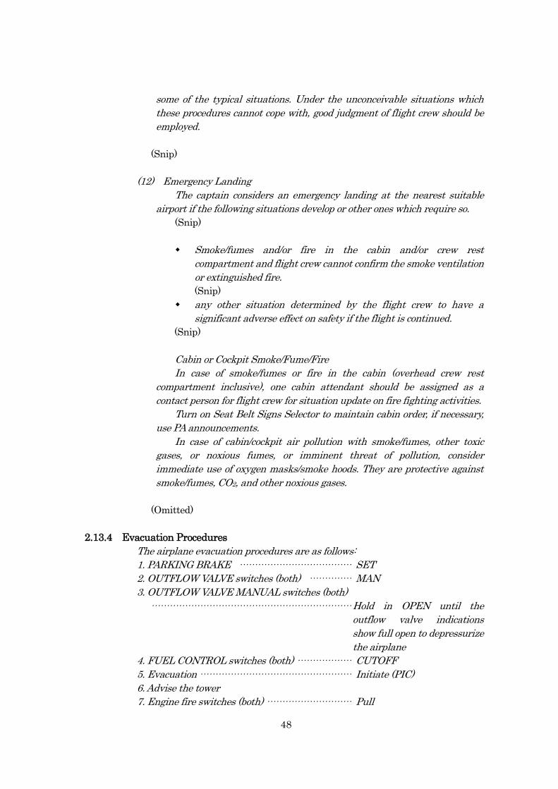
48
some of the typical situations. Under the unconceivable situations which
these procedures cannot cope with, good judgment of flight crew should be
employed.
(Snip)
(12) Emergency Landing
The captain considers an emergency landing at the nearest suitable
airport if the following situations develop or other ones which require so.
(Snip)
Smoke/fumes and/or fire in the cabin and/or crew rest
compartment and flight crew cannot confirm the smoke ventilation
or extinguished fire.
(Snip)
any other situation determined by the flight crew to have a
significant adverse effect on safety if the flight is continued.
(Snip)
Cabin or Cockpit Smoke/Fume/Fire
In case of smoke/fumes or fire in the cabin (overhead crew rest
compartment inclusive), one cabin attendant should be assigned as a
contact person for flight crew for situation update on fire fighting activities.
Turn on Seat Belt Signs Selector to maintain cabin order, if necessary,
use PA announcements.
In case of cabin/cockpit air pollution with smoke/fumes, other toxic
gases, or noxious fumes, or imminent threat of pollution, consider
immediate use of oxygen masks/smoke hoods. They are protective against
smoke/fumes, CO2, and other noxious gases.
(Omitted)
2.13.4 Evacuation Procedures
The airplane evacuation procedures are as follows:
1. PARKING BRAKE ····································· SET
2. OUTFLOW VALVE switches (both) ·············· MAN
3. OUTFLOW VALVE MANUAL switches (both)
·································································· Hold in OPEN until the
outflow valve indications
show full open to depressurize
the airplane
4. FUEL CONTROL switches (both) ·················· CUTOFF
5. Evacuation ·················································· Initiate (PIC)
6. Advise the tower
7. Engine fire switches (both) ···························· Pull
49
8. APU fire switch ············································ Override and pull
9. If an engine or APU fire warning light is illuminated:
Illuminated fire switch ································ Rotate to the stop and hold for
1 second.
2.13.5 History of Overnight Stay before the Serious Incident
The history of airplane’s overnight stay up until the serious incident (December
1, 2012 through January 15, 2013) revealed that the lowest outside temperature was
-2.6°C on 23 December, 2012. (See Figure 5: Lowest Temperature at Overnight Stay
Airports (Dec. 1, 2012-Jan. 15, 2013)
50
3 ANALYSIS
3.1 Airman Competence Certificate
The Captain and the FO held valid airman competence certificates and valid
aviation medical certificates.
3.2 Aircraft Airworthiness Certificate
The airplane had a valid airworthiness certificate and had been maintained and
inspected as prescribed.
3.3 Relations to the Meteorological Conditions
The similar incidents in Boston, Takamatsu and Narita all occurred in January,
during the cold season. Although statistical samples are insufficient, the fact that
they all occurred in winter is non-negligible, suggesting that low temperature is a
possible contributing factor.
3.4 Developments from Battery Failure to the Landing
a. Judging from the airplane’s location and altitude at the time of the
annunciation of battery malfunction in the cockpit, flight crew’s statements,
chronicled radio transmissions between the airplane and the air traffic
control facilities, the airplane landed uneventfully at Takamatsu Airport,
wasting least amount of time. The air traffic controller’s handling of the
other airplane that was supposed to land before the airplane to go around
very likely expedited the landing of the serious incident airplane.
The CVR and FDR records demonstrate that the flight crew calmly
handled the situation in accordance with the procedure. The APU start-up,
usually a post-landing procedure, was done before the landing to secure
redundancy of auxiliary electric power. Electric power generation after the
APU start-up could have helped flight crew obtain emergency power for
public announcement in power loss conditions after engine shut-down with
failed main battery.
b. The very likely reason for burning smell
As shown in Figure 2: FDR records, the smoke ventilation system
started to function after the main battery voltage dropped. It is highly
probable that the system operated as designed. The smoke was extracted
overboard through the override valve and forward outflow valve, but part of
it was sucked in from the cabin air compression inlet, forwarded to the
cockpit and cabin to be sensed.
c. The emergency lights are designed to be automatically illuminated in case of
loss of airplane electric power (zero HBB power). It is very likely that the
loss of HBB power as a result of the main battery failure triggered the first
indication of the EMER LIGHTS on the EICAS screen as designed.
51
3.5 Evacuation
Judging from the Captain’s statement and CVR records, it is very likely that he
decided to execute the evacuation when he received the positive response of the air
traffic controller on the smoke from the airplane. Judging from the CAs’ statements,
some passengers brought their belongings, but most of them slid the emergency
evacuation slides leaving their belongings on the plane as per the CAs’ instruction. It
is very likely that the evacuation went smoothly although four passengers suffered
minor injuries.
The fire fighting vehicles from the airport rescue and fire fighting service were
already in position by the runway prior to the landing of the airplane.
3.6 FDR Battery Voltage Record
As described in section 2.11.1, as the discrepant circuit card assembly was
installed on the airplane, it allowed the currents to flow from the APU battery to the
main battery circuit when main battery voltage was lower than that of the APU. As
Fig. 2.11.1 illustrates, the main battery sensor for the FDR picks up the APU battery
voltage. Therefore, it is highly probable that at the time of the main battery failure,
FDR main battery voltage recorded 11 V that was the sneak voltage from the APU
battery, and the actual main battery voltage was less than 11 V.
The presence of the discrepant circuit card assembly indicates that the airplane
was delivered to ANA as a result of imperfect final delivery check.
3.7 Analysis of Kakuda Testing
3.7.1 Cell Behavior upon Internal Short Circuit
As described in section 2.11.5.b, and the records in Figure 11-1: Detailed cell
voltage drop (Configuration 2), Appendix 2 illustrates, cell internal pressure
increased and it vented right after the internal short circuit occurred. The cell
voltage temporally dropped by approximately 1 V, recovered to 4 V and finally
dropped to 0 V.
The internal short circuit of a winding very likely caused positive and negative
electrodes to contact, generating high currents resulting in decomposition of
electrolyte and cell venting.
The shorted winding possibly consumed electrical energy to become a
carbonized conductor, and currents from the two parallel windings flowed in the
conductor resulting in voltage drop due to internal resistance, leading to the voltage
drop.
The possible reason for the recovery of cell voltage is that the cathode current
collectors of the shorted winding fused open and shut the current flow. As the
cathode terminal current collectors are made of aluminum while that of anode
current collector is copper, the difference of their melting point very likely explains
the reason of fused current collectors.
Cell internal heat very likely melted the separators of the remaining windings
resulting in short circuit and the cell voltage dropped to 0 V.
52
3.7.2 Irregular Contactor Opening upon Cell Venting
As described in section 2.11.5, the tests conducted in configurations 2 and 3 at
Kakuda exhibited contactor openings when cells vented. As described in section
2.6.5.4, the contactor is designed to open when cell voltage reach overcharge
threshold. When the contactor opened in the tests, no voltage data for each cell and
battery suggested the overcharging. Probable reasons for irregular contactor
opening under non-overcharging conditions are effects of spewed cell material or
heat generated by the failed cells on the BMU; however, the cause remained
undetermined. As the same phenomenon was observed in the battery vent test
conducted by Boeing, it is very likely that the cell venting is accompanied by
irregular contactor opening in the case of the LIB.
Irregular contactor opening occurs sometime within a few seconds or several
tens of seconds after the cell venting. When the contactor opens, battery voltage
instantaneously drops to 0 V.
The main battery is the primary backup power in case of multiple failures of
power sources on the airplane. Although the probabilities of cell venting under the
condition of multiple failures of power sources are very remote, it would be a grave
situation if that actually happened. In light of three similar battery events,
consideration should be given to the risk assessment of this issue.
3.7.3 Post-vent Short Circuit between Cell Case and Battery Box
As described in the section 2.11.5 b. and the Figure 11-1: “Fluctuations of Cell
Voltage and Ground Wire Current” in Appendix 2, approximately 1,000 A of ground
wire currents were recorded approximately 30 sec after the cell 6 venting. This
indicates that the concurrent physical contact between the swollen cell 6 and the
brace bar. At this stage, it is very likely that the failed cell itself was transformed
into a combined conductor which contains all the shorted windings and melted resin
sheets wrapping each winding, as described in section 3.7.1. The short circuit with
the battery box very likely caused both terminals of cell 6 to have equal electric
potential with the ground; however, no battery voltage drop is recorded in the test.
As described in the section 2.11.6.5, the battery voltage drop during ground wire
high currents was observed in the battery vent test performed by Boeing. It was very
likely caused by the mechanism in which shorted point to the battery box became
the ground voltage potential.
As the short circuits between the cell case and battery box occur erratically, the
corresponding voltage values probably fluctuate accordingly.
3.7.4 Arcing
The tests conducted in configurations 1 and 2 at Kakuda demonstrated fused
spots between cell 6 case and the brace bar, which was caused by arcing. Given the
currents as high as 1,000 A that ran through the ground wire, it is very likely that
the phenomenon similar to arc-welding occurred when shorted points detached from
the brace bar due to erratic short circuits between cell 6 case and brace bar. The
timing when cell 6 case was welded to the brace bar very likely corresponds to the
53
timing when the last high currents ran through the ground wire and cell 7 vented.
When two live contact points repeatedly continue to open and close,
arc-welding-like arcing occurs increasing the ambient temperature.
In the test configuration 3 at Kakuda, no trace of arcing was confirmed. This
was very likely that establishing a short circuit path between the cell case and the
ground through the battery box was unable as the ground wire of the battery box
was not connected.
3.7.5 Fused Ground Wire
As described in the section 2.11.5 b. and the Figure 11-1: Fluctuations of Cell
Voltage and Ground Wire Current” in the Appendix 2, it is very likely that around
the time when cell 7 vented, internal short circuit in the cell, caused by heat
propagation from cell 6, increased its internal pressure causing the case to swell.
Swollen cell 7 very likely pushed the brace bar towards cell 6, reestablishing short
circuit path allowing high currents to run through the ground wire. The timing of
the contact coincided with 1,630 A of currents through the wire just after cell 7
venting. The next high current jump to 1,010 A coincided with bursts of flames
preceded by sputtering sound. This demonstrates that the ground wire fused at the
timing of the second current jump.
As the ground wire used in the test was not identical with the airplane ground
wire in terms of length and material—different electric resistance. Because the
current value at which the wire was fused is an acceptable value considering the
wire resistance, the test probably simulated the high currents which fuse the wire in
the serious incident.
3.7.6 Differed Results between Test Configurations 2 and 3
The Kakuda test demonstrated clear difference in heat propagation between
configurations 2 and 3.
The tests in configurations 1 and 2 resulted in arcing while that in configuration
3 did not.
Erratic cell case-to-brace bar contacts or cell case-to-battery box result in arcing
generating arc welding-like phenomenon. Erratic arcing radiates heat and the cell
temperature probably becomes higher than that of cell heat generation. The possible
major reasons why configurations 1 and 2 demonstrated heat propagation while the
configuration 3 did not are as follows:
With the ground wire connected, it allows high currents to run through in case
of short circuit between the cell case and brace bar (battery box) resulting in
arcing;
Without the ground wire, high currents result in no arcing.
3.8 Main Battery Thermal Runaway Scenario
3.8.1 Sequence of Venting
a. The order of venting based on the CT scan image
Prior to the opening of the safety valve, pressure within a venting cell
causes it to swell and sides of neighboring cells are pushed in. As described
54
in the section 2.6.5.2, venting occurs when internal cell pressure reaches
certain threshold. Once the safety valve has been opened, the internal
pressure is released and the cell case loses the stiffness that resulted from
the internal pressure. When a neighboring cell swells, it pushes into the first
cell deforming its side. Judging from the deformation observed in the CT
scan image in Fig. 2.8.3-3: CT scan Image, the cell that vented first was
either cell 3 or cell 6, and the order of venting for other cells are as follows:
Cell 3 venting was followed by cell 2 and then cell 1
Cell 6 venting was followed by cell 7 and then cell 8
b. Initiating cell
As described in the section above, either cell 3 or cell 6 was very likely
the venting initiator.
The FDR battery voltage fluctuation depicted in Figure 3 illustrates
that the voltage dropped from 29 V to 14 V in 2 sec, followed by another drop
to 11 V in 2 sec. The actual main battery voltage at the time when FDR
recorded main battery voltage as 11 V was very likely less than 11 V as
described in section 3.6. The possible causes for voltage drop are as follows:
(1) Contactor behavior after venting
As described in section 3.7.2, irregular contactor opening was
observed after venting. Contactor opening disrupts physical and
electric connection so that voltage instantaneously drops to 0 V.
Irregular contactor opening occurs sometime within a few
seconds or several tens of seconds after the cell venting.
(2) Short circuit between cell case and battery box
As described in section 3.7.3, the short circuit with the brace
bar (battery box) may have caused the vented cell’s potential to
drop to the ground potential resulting in a battery voltage drop.
In the case of short circuit between the cell case and brace bar, if the
vent initiator were cell 3, recorded battery voltage would be 20 V (total
voltage of cell 4 through cell 8); if the initiator were cell 6, battery voltage be
8 V (total voltage of cell 7 and 8). Judging from the description in section 3.6,
the actual main battery voltage was less than 11 V, the initiator cell was
very likely cell 6.
Another reasoning for cell 6 as the initiator. As the welded brace bar to
cell 6 in configurations 2 and 3, Kakuda testing shows if cell 6 vents first,
swollen cell 6 makes contacts with the brace bar leading to short circuits. As
the contacts are erratic, arcing between cell 6 S1 and the brace bar was big
and this does not contradict the cell 6 damage. Furthermore, cell
6-to-brace-bar welding at Kakuda testing very closely resembles that of the
serious incident. This fact also supports the theory that the initiating cell
was cell 6.
3.8.2 Contactor Opening
The assumption that the cell-case-to-battery-box short circuit had continued
during the period of FDR voltage of 11 V as stated in section 3.8.1, contradicts the
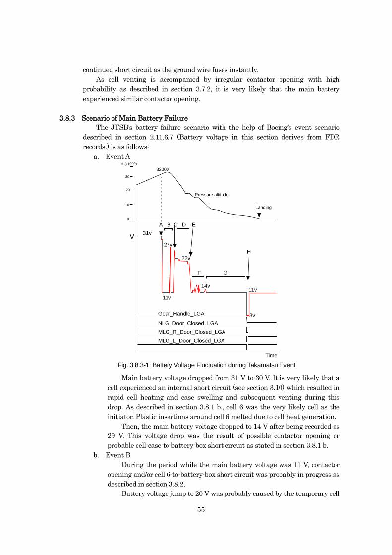
55
continued short circuit as the ground wire fuses instantly.
As cell venting is accompanied by irregular contactor opening with high
probability as described in section 3.7.2, it is very likely that the main battery
experienced similar contactor opening.
3.8.3 Scenario of Main Battery Failure
The JTSB’s battery failure scenario with the help of Boeing’s event scenario
described in section 2.11.6.7 (Battery voltage in this section derives from FDR
records.) is as follows:
a. Event A
31v
27v
11v
14v
22v
3v
11v
A B C D E
F G
H
Gear_Handle_LGA
NLG_Door_Closed_LGA
MLG_R_Door_Closed_LGA
MLG_L_Door_Closed_LGA
V
Fig. 3.8-1: Battery Voltage Fluctuation During Takamatsu Event (second posting)
32000
0
30
20
10
ft (x1000)
Landing
Pressure altitude
Time
Main battery voltage dropped from 31 V to 30 V. It is very likely that a
cell experienced an internal short circuit (see section 3.10) which resulted in
rapid cell heating and case swelling and subsequent venting during this
drop. As described in section 3.8.1 b., cell 6 was the very likely cell as the
initiator. Plastic insertions around cell 6 melted due to cell heat generation.
Then, the main battery voltage dropped to 14 V after being recorded as
29 V. This voltage drop was the result of possible contactor opening or
probable cell-case-to-battery-box short circuit as stated in section 3.8.1 b.
b. Event B
During the period while the main battery voltage was 11 V, contactor
opening and/or cell 6-to-battery-box short circuit was probably in progress as
described in section 3.8.2.
Battery voltage jump to 20 V was probably caused by the temporary cell
Fig. 3.8.3-1: Battery Voltage Fluctuation during Takamatsu Event
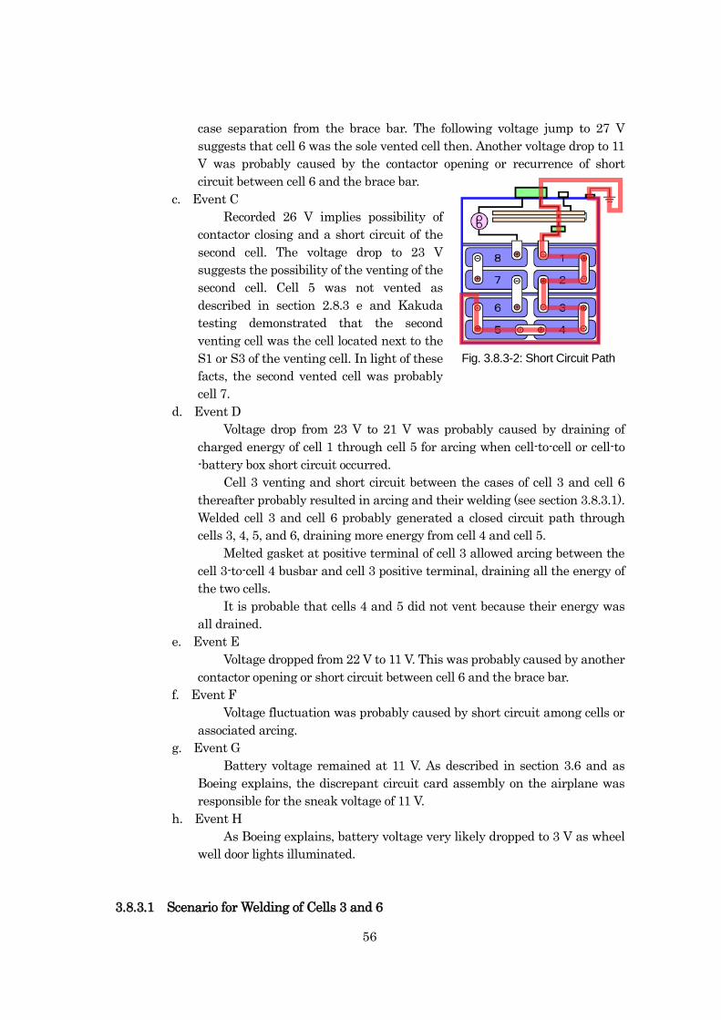
56
case separation from the brace bar. The following voltage jump to 27 V
suggests that cell 6 was the sole vented cell then. Another voltage drop to 11
V was probably caused by the contactor opening or recurrence of short
circuit between cell 6 and the brace bar.
c. Event C
Recorded 26 V implies possibility of
contactor closing and a short circuit of the
second cell. The voltage drop to 23 V
suggests the possibility of the venting of the
second cell. Cell 5 was not vented as
described in section 2.8.3 e and Kakuda
testing demonstrated that the second
venting cell was the cell located next to the
S1 or S3 of the venting cell. In light of these
facts, the second vented cell was probably
cell 7.
d. Event D
Voltage drop from 23 V to 21 V was probably caused by draining of
charged energy of cell 1 through cell 5 for arcing when cell-to-cell or cell-to
-battery box short circuit occurred.
Cell 3 venting and short circuit between the cases of cell 3 and cell 6
thereafter probably resulted in arcing and their welding (see section 3.8.3.1).
Welded cell 3 and cell 6 probably generated a closed circuit path through
cells 3, 4, 5, and 6, draining more energy from cell 4 and cell 5.
Melted gasket at positive terminal of cell 3 allowed arcing between the
cell 3-to-cell 4 busbar and cell 3 positive terminal, draining all the energy of
the two cells.
It is probable that cells 4 and 5 did not vent because their energy was
all drained.
e. Event E
Voltage dropped from 22 V to 11 V. This was probably caused by another
contactor opening or short circuit between cell 6 and the brace bar.
f. Event F
Voltage fluctuation was probably caused by short circuit among cells or
associated arcing.
g. Event G
Battery voltage remained at 11 V. As described in section 3.6 and as
Boeing explains, the discrepant circuit card assembly on the airplane was
responsible for the sneak voltage of 11 V.
h. Event H
As Boeing explains, battery voltage very likely dropped to 3 V as wheel
well door lights illuminated.
3.8.3.1 Scenario for Welding of Cells 3 and 6
Fig. 3.8.3-2: Short Circuit Path
57
Heat radiation from arcing associated with cell 6 to brace bar probably melted
separators within cell 7 and cell 3 eventually leading to internal short and venting.
It is probable that swollen cell 3 touched cell 6 S2, induced arcing and consequently
welded them together.
Welded cell 3 and cell 6 allowed a closed short circuit path to form with cell 4
and 5. It is probable that the resin gasket below cell 3 positive terminal melted due
to radiated heat creating a gap between the positive terminal plate and busbar,
causing opening and closing of live terminals which lead to arc-welding-like arcing
and consequently melted cell 3 positive terminal, cell header around the positive
terminal, fixing bolt and the busbar itself.
3.9 Phenomena Observed during Charging/Discharging
3.9.1 Fluctuation of Charging Currents
As described in sections 2.11.3, 2.11.4 and 2.11.6.1, cell balancing test, on-board
test and battery-BCU test exhibited small oscillation of charging currents. Although
the amplitude of fluctuations is fairly small compared to the battery capacity, it is
desirable that their negative characteristics—repeated shallow charging and
discharging, unnecessary fluctuation, possible negative impact on battery
life—should be improved.
3.9.2 Phenomenon of High Transient Voltage during Discharging
As described in section 2.11.6.1, in the test simulating a nominal APU start with
engines running (battery output current 20 A), each cell and battery registered a
high transient voltage. Approx. 1 sec after the contactor BIT criteria was met,
current interruption occurred for 22 msec instantaneously followed by the high
transient voltage. Judging from the occurrence, BIT function of the BMU is probably
responsible for the phenomenon described in section 2.6.5.3. f.
During the on-board test, a momentary voltage drop to 0 V was observed during
a discharge of approximately 60 A. As this phenomenon was observed approximately
1 sec after the charging current dropped below a set threshold, accompanied by a
current interruption of approximately 23 msec, contactor BIT function of the BMU is
probably responsible for the phenomenon.
Given the fact that contactor BIT runs during the discharging phase, actual
airplanes possibly experience high transient voltage applied to each cell.
3.9.3 Phenomenon of Voltage Spike during Charging
As described in section 2.11.4.b, during the on-board test, a voltage spike up to
approximately 45 V was observed during 46 A charging. As the spike was observed
approximately 1 sec after the charging currents went below the set threshold and
the charging currents were interrupted for approximately 25 msec. BMU’s contactor
BIT function is probably responsible for the phenomenon.
BMU’s contactor BIT operation is not intended in the original design
philosophy—the BIT should not run while the charging current is high, but at the
last phase of charging operation where charging current is less than the set
threshold to avoid high voltage transient which is associated with the contactor
58
opening. Therefore, it is desirable that the phenomenon should be improved.
3.10 Cause of Heat Generation
As described in section 2.7.2, conceivable major causes for battery heat
generation are overcharging, over-discharging, external short circuit, cell case short
circuit, and internal short circuit. Possibility of each cause is analyzed as follows:
a. Overcharging
Overcharging accompanies voltage increase; however, the FDR records
showed no increase of the main battery voltage. This fact demonstrates the
absence of overcharging at battery level.
Overcharging derived from imbalanced cells would leave traces of fire
damage around the battery box as described in the section 2.12.7.4 b.;
however, there was no trace of fire damage around the main battery as
described in section 2.8.3, it is very likely that cell-level overcharging
deriving from cell imbalance is very unlikely.
b. Over-discharging
Over-discharging accompanies voltage decrease; however, the FDR
records in Figure 2 showed no main battery voltage decrease. This fact
demonstrates the absence of over-discharging at battery level.
c. External short circuit
As described in section 2.12.7.3 a., when exterior circuit resistance of
the battery is very small, a short circuit allows several thousand amps of
current to run through the circuit fusing aluminum cell current collectors,
leaving no battery exterior damage. When the exterior circuit resistance is
high as described in section 2.12.7.3 b, the J3 cable connector suffers
damage. But none of the airplane J3 connector, J1 cable, or J3 cable
exhibited damage as described in section 2.8.3. These facts demonstrate
small possibility of external short circuit.
d. Short circuit of cell case
As described in 2.11.6. 2 and 2.11.6.9 a., cell-case-to-ground direct
shorting or that via saline solution can lead to a cell venting. According to
the EX Report, short circuit between cell case and battery box is associated
with distinctive damage; however, the incident battery did not have such
damage. This fact indicates that the possibility of cell case short is low.
e. Internal short circuit
As possibilities of above mentioned causes for heat generation are low, it
is possible that the cause of battery heat generation was internal short
circuit.
3.11 Causes for Internal Short Circuit
As concluded in section 3.10, internal short circuit is a likely cause for cell heat
generation. The JTSB analyzed possibilities for major causes stated in section 2.7.2
e.
3.11.1 Foreign Object in a Cell
59
As stated in sections 2.11.6.9 b, and 2.13.2.b, small copper pieces were found in
two cells.
Against these facts, GYT maintains that the possibility of foreign object’s cell
contamination during manufacturing, which contributes to internal short circuit is
low, because:
Cells are manufactured in environmentally controlled clean rooms (Section
2.13.1.3 a.);
Cells are subjected to internal short circuit test (Section 2.13.1.3.b.);
Cells are subjected to soft short test and CT scanning (Section 2.13.1.3 b.); and
Safety records proved by other-than-aviation purpose cells which share the
identical cell ingredients and manufacturing processes (Section 2.13.1.1).
Metal particles migrated in a cell during DPA (2.13.2.b)
However, metal pieces were found not from a single cell but from two cells. As
stated in section 2.11.6.9 b, Ex Report states that the possible cause of metal FOD
derives from cell manufacturing. Given these facts, it may be impossible to deny the
possibility of metal FOD.
3.11.2 Separator Damage
Possible separator damage is caused by crack, melting and shrinking. Cracks
can be caused from tensile stress during winding rolling and generated during
charging and discharging.
a. Crack during manufacturing
This type of crack would be probably detected by inspection during and
after manufacturing. In addition, as described in section 2.13.1.1, GYT
maintains that it has received no reports of anomalies for the large-sized
multi-purpose batteries manufactured using the same cell ingredients and
manufacturing methods. These facts suggest the low possibility of separator
damage during manufacturing.
b. Crack during charging and discharging
As described in 2.11.6.9 c, there was a case where agglomerates were
discovered, whose diameter was larger than that of normal positive material.
This may not be an ideal condition for active material; however, the
possibility of separator damage triggered by an agglomerate whose size is
less than thickness of active material layer is probably low.
c. Melting and shrinking by heat
One possible factor is external heat transferred to cell interior causing
separator shrinkage. As described in 2.11.7.1, the simulated APU start test
done by the NTSB confirmed the phenomenon of increased rivet
temperature. It is possible that increased resistance at cell terminals cause
increased Joule heat (=I2 x R) which is transferred via current collectors, and
the heat subsequently causes separator shrinkage leading to an internal
short circuit.
However, the battery involved in the serious incident was the main
battery. As stated in section 2.6.3, its maximum discharging currents are
around one sixth of that of the APU battery. Given this fact, it is unlikely
60
that serious incident main battery experienced increased rivet temperature.
3.11.3 Lithium Metal Deposition
a. Effects of low-temperature environment
In the serious incident, the battery suffered severe heat damage
making it impossible to analyze microscopic structure of the cells. In light of
the fact that all similar incidents occurred in cold season, it is probably
difficult to deny the effects of cold conditions on internal short circuit.
Airplane interior temperature during overnight stay varies depending
on outside temperatures. Therefore, the LIBs were very likely exposed to
low temperatures during winter overnight stay. Upon the airplane power-up,
EE bay temperature rises in short time, but cell core temperature does not
reach EE bay temperature in short time. There is also a possibility that
battery surface temperature was near zero during flight operations as
described in section 2.13.2 b. Given these two facts, it is possible that
repeated irregular charging and discharging were conducted with low cell
core temperatures during the cold season, which derived from service
destinations and accompanying routes.
b. Flexural deformation and wrinkles on anode
A flattened anode roll exhibited flexural deformations (see section
2.13.1.1 b), while another battery withdrawn from another 787 exhibited the
same deformations (see sections 2.11.2.b and 2.13.2 b). EX Report includes a
discovery of gaps in the electrodes.
As described in section 2.7.4, non-uniform winding formation such as
flexural deformation and wrinkles may produce non-uniform distance
between the electrodes and localized charging currents concentration leads
to accelerated lithium metal deposition.
Battery charging and discharging or cell manufacturing process is
possible contributing factor for wrinkle formation.
c. Degradation of cell interior
As the serious incident battery was on board the airplane for about
three months as described in section 2.5.1, the possibility of cell interior
degradation associated with service duration was probably remote.
However, as described in section 3.9.1, the BCU exhibited small
oscillation of charging currents which deemed to pose negative effects on
battery life. This suggests that the current fluctuation degrades cell interior
causing anode active materials to become non-uniform eventually affecting
the cell performance.
d. Lithium metal deposition in the serious incident main battery
As described in sections 2.11.7.2 and 2.11.8.1, the NTSB and GYT
performed testing to identify lithium metal deposition.
The NTSB testing observed the deposition which has lithium metal
features; however, deposit ingredients were not definitively verified and
lithium metal was not identified. This is because of lithium’s high reactive
character which evades its detection and possible detection methods have
61
limitations.
GYT maintains that its testing did not identify the presence of lithium
metal.
e. Lithium metal deposition in the serious incident main battery
Lithium metal was not identified in the testing. But as the following
findings are confirmed as described in above a., b., and c., lithium metal had
probably deposited in the serious incident main battery.
Effects of low temperature environment on charging.
Wrinkles discovered on anode in the same type LIB.
Possibility of non-uniform anode active material due to degraded
anode active material.
f. Possibility of internal short circuit caused by lithium metal deposition
The serious incident main battery had possible lithium meal deposition
as described in above sub-section e. However, if the main battery was used
under proper conditions, internal short circuit deriving solely from lithium
metal deposition is very unlikely (see section 2.7.4).
However, as stated in sections 3.9.1 and 3.9.2, fluctuating charging
currents and transient peak voltage are observed on 787 battery system, it is
possible that these electric transient or other factors combined may have
affected the lithium metal deposition leading to an internal short circuit.
3.11.4 Summary of Internal Short Circuit Cause
From the analyses of internal short circuit stated in sections 3.11.1 through
3.11.3, we have three possible candidates for interior short circuit: lithium metal
deposition in the cell, metal piece contamination, and damaged separator. Given the
fact that all similar battery incidents occurred in January, during cold season,
among three candidates, lithium metal deposition deriving from charging under cold
conditions could have existed. However, it is unlikely that lithium metal deposition
was the sole causal factor of the internal short circuit leading to venting. It is
possible that these electric transient or other factors combined may have affected the
lithium metal deposition leading to an internal short circuit.
Note that analyses in sections 3.11.1 through 3.11.3 only provide possible causes
of internal short circuit, and as no mechanism of internal short circuit was
conclusively identified, we cannot exclude the possible involvement of other factors
associated with design and manufacturing.
3.12 Type Certificate
3.12.1 Applicability of Type Certificate
3.12.1.1 Issue Paper
As described in the section 2.12.4 a., the FAA noted safety problems with
lithium-ion batteries, which included overcharging, over-discharging, and
flammability of cell components. Among them failure mode includes overcharging
and over-discharging. As described in section 2.11.6.8, the cause-effect diagram
prepared by Boeing help renew failure modes which include external short circuit
and internal short circuit other than overcharging and over-discharging. As
62
described in section 2.11.5, Kakuda testing demonstrated a thermal runaway
derived from internal short circuit. The FAA probably underestimated the risk of
internal short circuit during special condition study. In light of this, it should have
studied all the failure modes including external and internal short circuit.
3.12.1.2 Special Conditions 25-359-SC
The special conditions consist of nine conditions (see section 2.12.4.b). The
second condition states “Design of the lithium-ion batteries must preclude the
occurrence of self-sustaining, uncontrolled increases in temperature or pressure.”
Based on this condition and its interpretation, as described in section 2.12.6.2, the
TC safety assessment allowed “battery vents smoke/fire,” to have quantitative
probability of less than 1 x 10⁻⁹ per flight hour, and “Battery vent and/or smoke
(without fire)” quantitative probability of less than 1 x 10⁻⁷ per flight hour.
The Boston event preceded the serious incident by nine days. At the time of the
serious incident, the global 787 fleet accumulated flight time of approximately
50,000 hr. This means the actual statistical probability for the event “Battery vent
and/or smoke (without fire)” to become 4 x 10⁻⁵ per flight hour, well above the
expected 1 x 10⁻⁷ per flight hour.
3.12.1.3 Probability of Cell Failure
As described in 2.12.6.4, according to the failure modes and effects analysis
conducted for type certification, GYT established 787 LIB failure rate based on the
industrial LIB cell failure record, which is similar in cell structure. However, at the
time of the analysis, failure reports of the industrial LIB did not reach GYT, so that
it established probability of cell failure based on zero failure counts and total
operational duration, calculating MTBF using Poisson distribution.
The volume difference between the industrial battery cell and that of 787
battery was corrected using coefficient. For the calculation, confidence level of 60%
was used. For general statistical analysis, confidence level of 95% or 99% is used;
however, it is possible that the confidence level of 60% stated in Japanese Industrial
Standards (JIS) C 5003 was used. It should be noted that the JIS standard applies to
electronic parts which are continually manufactured based on substantially identical
design under established quality control, and which ensure reasonable deduction of
the probability of failure.
As described in section 2.12.6.4, GYT states that the active material ingredients
for the large industrial battery cell and that of 787 battery are not identical. It is
possible that calculation of probability of failure, based on performance records of the
large industrial LIB whose occurrence conditions for overcharging, over-discharging,
and internal short circuit are not proven to be equal to those for the 787 batteries,
was inappropriate as a method for TC safety assessment.
On the other hand, JIS C 5003 stipulates the method of estimation for
probability of failure using confidence level of 90%. The estimation using JIS method
should have been calculated using widely used confidence level of 95% or JIS
confidence level of 90%.
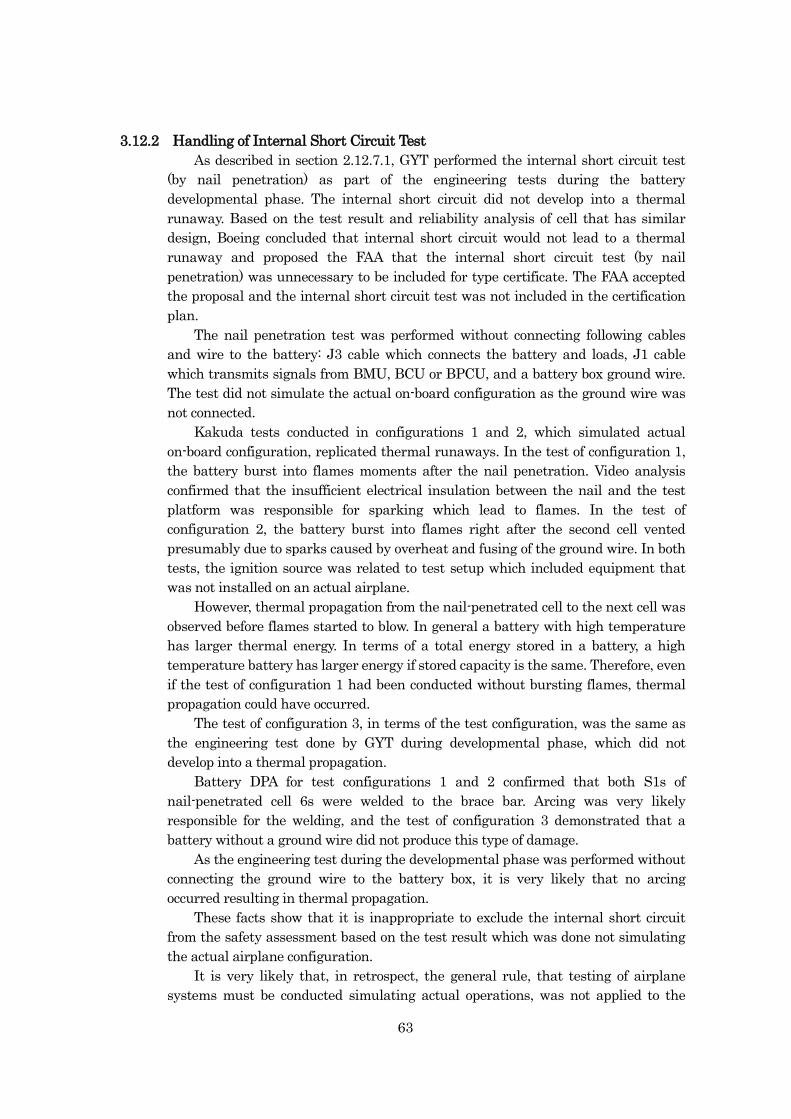
63
3.12.2 Handling of Internal Short Circuit Test
As described in section 2.12.7.1, GYT performed the internal short circuit test
(by nail penetration) as part of the engineering tests during the battery
developmental phase. The internal short circuit did not develop into a thermal
runaway. Based on the test result and reliability analysis of cell that has similar
design, Boeing concluded that internal short circuit would not lead to a thermal
runaway and proposed the FAA that the internal short circuit test (by nail
penetration) was unnecessary to be included for type certificate. The FAA accepted
the proposal and the internal short circuit test was not included in the certification
plan.
The nail penetration test was performed without connecting following cables
and wire to the battery: J3 cable which connects the battery and loads, J1 cable
which transmits signals from BMU, BCU or BPCU, and a battery box ground wire.
The test did not simulate the actual on-board configuration as the ground wire was
not connected.
Kakuda tests conducted in configurations 1 and 2, which simulated actual
on-board configuration, replicated thermal runaways. In the test of configuration 1,
the battery burst into flames moments after the nail penetration. Video analysis
confirmed that the insufficient electrical insulation between the nail and the test
platform was responsible for sparking which lead to flames. In the test of
configuration 2, the battery burst into flames right after the second cell vented
presumably due to sparks caused by overheat and fusing of the ground wire. In both
tests, the ignition source was related to test setup which included equipment that
was not installed on an actual airplane.
However, thermal propagation from the nail-penetrated cell to the next cell was
observed before flames started to blow. In general a battery with high temperature
has larger thermal energy. In terms of a total energy stored in a battery, a high
temperature battery has larger energy if stored capacity is the same. Therefore, even
if the test of configuration 1 had been conducted without bursting flames, thermal
propagation could have occurred.
The test of configuration 3, in terms of the test configuration, was the same as
the engineering test done by GYT during developmental phase, which did not
develop into a thermal propagation.
Battery DPA for test configurations 1 and 2 confirmed that both S1s of
nail-penetrated cell 6s were welded to the brace bar. Arcing was very likely
responsible for the welding, and the test of configuration 3 demonstrated that a
battery without a ground wire did not produce this type of damage.
As the engineering test during the developmental phase was performed without
connecting the ground wire to the battery box, it is very likely that no arcing
occurred resulting in thermal propagation.
These facts show that it is inappropriate to exclude the internal short circuit
from the safety assessment based on the test result which was done not simulating
the actual airplane configuration.
It is very likely that, in retrospect, the general rule, that testing of airplane
systems must be conducted simulating actual operations, was not applied to the
64
certification test.
3.12.3 Latest LIB Airworthiness Standards (TSO-179a/RTCA DO-311)
As described in section 2.12.8, the latest version of LIB airworthiness standards
is TSO-179a, and its minimum operational performance standards refer to RTCA
DO-311 as specific standards.
However, RTCA DO-311 does not stipulate test procedures to properly simulate
internal short circuit. Even if TSO-179a/ RTCA DO-311 had been applied to 787 LIB
certification standards, it would not be certain whether internal short circuit tests
could have been conducted properly simulating the internal short circuit under
on-board environment. RTCA DO-311 should be amended to mandate internal short
circuit tests simulating proper on-board environment.
65
4 CONCLUSIONS 4.1 Findings
The analysis on the main battery failure is summarized as follows. (For the
details, see the section enclosed in parentheses at the end of each section.)
a. Influence of meteorological conditions
We cannot disregard the fact that all battery incidents (the serious
incident inclusive) occurred in winter. Therefore, at present low temperature
environment was the possible contributing factor to the battery failure.
(Section 3.3)
b. Analysis of Kakuda testing
(1) Irregular contactor opening upon venting
Tests exhibited contactor openings under non-overcharging
conditions. (Section 3.7.2)
(2) Post-vent short circuit between cell case and battery box
In the test of configuration 2, approximately 1,000 A of ground
wire currents were recorded approximately 30 seconds after the
cell 6 venting. This indicates that the concurrent physical contact
between the swollen cell 6 and the brace bar occurred at the cell
vent timing. The short circuit with the battery box very likely
caused both terminals of cell 6 to have equated electric potential
with the ground. (Section 3.7.3)
(3) Arcing
The test of configuration 2 demonstrated fused spots between
cell 6 case and the brace bar, which was caused by arcing. Given
the fact that large currents run through the ground wire, it is very
likely that erratic arcing between cell 6 and the brace bar was
similar to arc-welding.
(Section 3.7.4)
(4) Fused ground wire
The ground wire very likely fused open when high currents of
1,010 A ran after cell 7 vented. (Section 3.7.5)
(5) Differed results between Kakuda test configurations 2 and 3
The possible major reason why the test of configuration 2
demonstrated heat propagation while that of configuration 3 did
not is as follows: With the ground wire connected, it allows high
currents to run through in case of short circuit between the cell
case and brace bar (battery box) resulting in arcing; without the
ground wire, high currents result in no arcing.
(Section 3.7.6)
c. Scenario of main battery failure
(1) Judging from the deformation observed in the CT scan image, the
cell vented first was very likely either cell 3 or cell6. Judging from
FDR main battery voltage value, Kakuda test results, and the
battery damage, the initiating cell was very likely cell 6.
(Section3.8.1)
66
(2) As it is confirmed that high probability of contactor opening is
associated with a cell venting, it is very likely that the main
battery experienced similar contactor opening. (Section 3.8.2)
d. Phenomenon observed during charging/discharging
(1) Fluctuated charging currents
Although the amplitude of fluctuated charging current
identified in the on-board test is fairly small in light of battery
capacity, it is desirable that their negative
characteristics—repeated shallow charging and discharging,
unnecessary fluctuation, and possible negative impact on battery
life—should be improved. (Section 3.9.1)
(2) Phenomenon of high transient voltage during discharging
Tests conducted by Boeing revealed that BIT operation during
discharge is accompanied with high transient voltage applied to
each cell. On-board test also confirmed the same contactor BIT.
With these facts, it is possible that the serious incident airplane
experienced high transient voltage applied to each cell.
(Section 3.9.2)
e. Causes of heat generation
Possible major causes for battery heat generation are overcharging,
over-discharging, external short circuit, cell case short circuit, and internal
short circuit. The FDR records and battery damage suggest that the possible
cause of battery heat generation is, among other things, internal short
circuit. (Section 3.10)
f. Causes of internal short circuit
(1) Metal object in a cell
The discovery of metal pieces in two cells probably makes it
difficult to completely deny the metal contamination.
(Section 3.11.1)
(2) Separator damage
Possible separator damage is caused by cracks generated by
tensile stress when a set of winding is rolled and by charging and
discharging, and heat-driven melting and shrinkage. In regard to
the heat-driven separator melting and shrinkage, as the heat
generation in the serious incident occurred in the main battery,
the possibility of resistive heating leading to heat generation
which consequently results in separator melting and shrinkage is
low. (Section 3.11.2)
(3) Lithium metal deposition
(a) Effects of low-temperature conditions
The fact that all similar incidents occurred in cold
season, it is probably difficult to deny the effects of cold
conditions on internal short circuit.
It is possible that repeated irregular charging and
discharging were conducted with low cell core
67
temperatures during the cold season, which derived from
service destinations and accompanying routes.
(Section 3.11.3 a.)
(b) Flexural deformation and wrinkles on the anode
There are possibilities that non-uniform winding
formation such as flexural deformations and wrinkles
produced non-uniform distance between the electrodes
accelerating lithium metal deposition.
It is also possible that battery charging and
discharging or cell manufacturing process is responsible
for wrinkle formation. (Section 3.11.3 b.)
(c) Degradation of cell interior
In the case of the serious incident main battery, the
possibility of cell interior degradation associated with
service duration may be remote.
However, the small fluctuations of BCU charging
currents which deemed to pose negative effects on battery
life indicates that it degraded cell interior, lead to
non-uniformity of anode active material, and affected the
battery performance. (Section 3.11.3 c.)
(d) Lithium metal deposition in the serious incident main
battery
Although lithium metal was not identified in the
testing, the following findings suggest that the lithium
metal had probably deposited in the serious incident main
battery:
Effects of cold temperature environment on
charging.
Wrinkles discovered on anode in the same type LIB.
Possibility of non-uniform anode active material
due to degraded anode active material.
(Section 3.11.3 e)
(e) Possibility of internal short circuit caused by lithium
metal deposition
If an LIB is used under proper conditions, internal
short circuit deriving solely from lithium metal deposition
is very unlikely.
The fluctuating charging currents and high transient
voltage are observed on 787 battery system, it is possible
that these electric transient or other factors combined
may have affected the lithium metal deposition leading to
an internal short circuit. (Section 3.11.3. f.)
(4) Cause of internal short circuit
From the analyses of internal short circuit, three possible
candidates for interior short circuit remain: lithium metal
68
deposition in the cell, metal piece contamination, and damaged
separator. Given the fact that all similar battery incidents
occurred in the cold season, lithium metal deposition deriving from
charging under cold conditions could have existed. However, it is
unlikely that lithium metal deposition was the sole causal factor of
the internal short circuit leading to venting. It is possible that
electric transient or other factors combined may have affected the
lithium metal deposition leading to an internal short circuit.
As no mechanism of internal short circuit was conclusively
identified, we are unable to exclude the possible involvement of
other factors associated with design and manufacturing. (Section
3.11.4)
g. Type certificate
(1) Applicability of type certificate
(a) Issue paper
The FAA noted safety problems with lithium-ion
batteries, which only included overcharging,
over-discharging, and flammability of cell components.
The FAA probably underestimated the risk of internal
short circuit during special condition study.
(Section 3.12.1.1)
(b) Special conditions 25-359-SC
At the time of the serious incident, the global 787 fleet
accumulated flight time of approximately 50,000 hr. This
meant the actual statistical probability for the event
“Battery vent and/or smoke (without fire)” to become 4 x
10-5 per flight hour, well above the estimated 1 x 10⁻⁷ per
flight hour. (Section
3.12.1.2)
(c) Probability of cell failure
The cell failure rate was calculated based on the
industrial LIB cell failure record, whose cell ingredients
are different from the 787 batteries. For the calculation,
expected confidence level was 60%. For general statistical
analysis, confidence level of 95% or 99% is used; however,
confidence level 60% that is stipulated in JIS C 5003 was
possibly used. (Section 3.12.1.3)
(2) Handling of internal short circuit test
Kakuda tests, which simulated actual on-board configuration,
replicated thermal runaways. The internal short circuit test
conducted by GYT during developmental phase not simulating the
actual on-board configuration did not develop into a thermal
runaway.
It was inappropriate to exclude the internal short circuit from
the TC tests based on the test which was conducted not simulating
69
the actual airplane configuration. (Section 3.12.2)
(3) Latest LIB airworthiness standards (TSO-179a/RTCA DO-311)
RTCA/DO-311, which is referred to by the latest version of LIB
airworthiness standard TSO-179a, does not stipulate test
procedures to properly simulate internal short circuit. It should be
amended to mandate internal short circuit tests simulating proper
on-board environment. (Section 3.12.3)
4.2 Probable Causes
The emergency evacuation was executed on Takamatsu Airport taxiway in the
serious incident, which was a consequence of emergency landing deriving from the
main battery thermal runaway during the airplane’s takeoff climb.
Internal heat generation in cell 6 very likely developed into venting, making it
the initiating cell, resulting in cell-to-cell propagation and subsequent failure of the
main battery. It is very likely that cell 6 internal heat generation and increased
internal pressure caused it to swell, melt the surrounding insulation material and
contact the brace bar creating a grounding path that allowed high currents to flow
through the battery box. The currents generated arcing internal to the battery that
contributed to cell-to-cell propagation consequently destroying the battery.
Cell 6 heat generation was probably caused by internal short circuit; however,
the conclusive mechanism thereof was not identified.
In the serious incident, the internal short circuit of a cell developed into cell
heat generation, thermal propagation to other cells, and consequently damaged the
whole battery. The possible contributing factors to the thermal propagation are that
the test conducted during the developmental phase did not appropriately simulate
the on-board configuration, and the effects of internal short circuit were
underestimated.
70
5. SAFETY ACTIONS 5.1 Safety Actions Taken by Boeing and Approved by the FAA
5.1.1 Safety Actions Taken by Boeing
a. Elimination of potential cell failure causes
(1) Improved busbar fastening nuts
(2) Reduced electrical stress to electrolyte
Improved cell insulation
Increased insulation for the battery case bottom
Improved cell-to-cell/cell-to-battery case isolation
Increased insulation for the battery top cover
Improved insulation for the brace bars
New drain holes for the bottom fixation frame and the
battery box against liquid condensation
Reduced BCU output voltage
Stabilized battery charging current
(3) Measures against over-discharging
Improved BMU
(4) Improved manufacturing practice
More rigid ATP
Improved quality control
b. Measures against cell-to-cell propagation
(1) Improved cell-to-cell/cell-to-battery case isolation
(2) New drain holes for the bottom fixation frame
(3) Improved internal wiring against heat
(4) Installation of tubing for vented gas to escape overboard.
c. Measures against battery venting
(1) Installation of an enclosure box (A battery is electrically floating in
this box, while the box is grounded to the CRN.)
(2) Installation of tubing for vented gas to escape overboard.
5.1.2 Effectiveness of the Safety Actions
As described in the section 2.13.2, b., JAL’s 787 parked at Narita International
Airport experienced a cell 5 venting while it was under preparation for the next
flight.
The JCAB is investigating this event. So far it is known: one cell vented; there
was no thermal propagation; electrolyte and other interior materials were trapped in
the battery box; and no arcing between the cell case and the brace bar occurred. The
vented gas was exhausted overboard through the dedicated tubing.
5.2 Safety Actions Taken by the FAA and JCAB
5.2.1 Safety Actions Taken by the FAA
On January 16, 2015 (Eastern Standard Time) the FAA issued the
airworthiness directive (AD) 2013-02-51 ordering the battery system to be modified
or other actions be taken in accordance with a method approved by the FAA before
further flight. At this time the global 787 fleet accumulated total of about 51,000
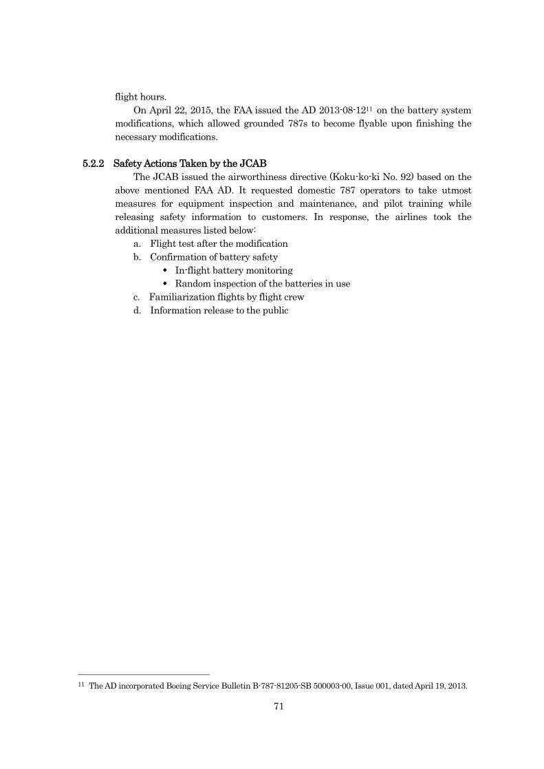
71
flight hours.
On April 22, 2015, the FAA issued the AD 2013-08-1211 on the battery system
modifications, which allowed grounded 787s to become flyable upon finishing the
necessary modifications.
5.2.2 Safety Actions Taken by the JCAB
The JCAB issued the airworthiness directive (Koku-ko-ki No. 92) based on the
above mentioned FAA AD. It requested domestic 787 operators to take utmost
measures for equipment inspection and maintenance, and pilot training while
releasing safety information to customers. In response, the airlines took the
additional measures listed below:
a. Flight test after the modification
b. Confirmation of battery safety
In-flight battery monitoring
Random inspection of the batteries in use
c. Familiarization flights by flight crew
d. Information release to the public
11 The AD incorporated Boeing Service Bulletin B-787-81205-SB 500003-00, Issue 001, dated April 19, 2013.
72
6 SAFETY RECCOMMENDATIONS 6.1 Actions to be taken by the FAA
The internal short circuit test by nail penetration method under the simulated
on-board configuration with the battery ground wire demonstrated a thermal
runaway, while the test without the ground wire did not.
Given the facts and analyses of other tests combined, in the serious incident the
very likely sequence of scenario for the main battery thermal runaway is as follows:
Cell 6 was the initiator of the thermal propagation;
Cell 6 and the brace bar contacted with each other allowing high currents to
flow through the battery box to cause arcing; and
Arcing bolstered the thermal propagation leading to the thermal runaway.
It is very likely that the engineering test conducted during the developmental
phase did not develop into thermal runaway because the battery box was not
grounded with the ground wire. This demonstrates that it was inappropriate to
exclude the internal short circuit test from the safety assessment based on the test
result which was not conducted simulating the actual airplane configuration.
There is a possibility that present standards for airplane LIB do not
appropriately address the electric environment although they stipulate
environmental conditions such as temperature, humidity, inertia, and so on. In
addition, the FTA in the safety assessment provided to the JTSB lacked the
assessment of the thermal propagation risk.
The probability of LIB vent with smoke was estimated to be less than one out of
ten million flight hours in the type certification; however, in reality three events of
cell heat generation have occurred in less than 250,000 flight hours, resulting in the
rate far exceeding the estimate. The calculation of failure rate in the type
certification, which was done based on the failure records of similar LIB, was
probably inappropriate.
In addition, contactor opening not expected in the design is very likely
associated with cell venting; therefore, the necessity for risk reassessment on the
loss of all electric power should be examined.
The JTSB, in light of the serious incident investigation, makes the following
safety recommendations that the Federal Aviation Administration of the United
States of America should take the following mitigation actions.
The FAA should:
a. Provide instruction to airplane manufactures and equipment manufactures
to perform equipment tests simulating actual flight operations.
b. Review the technical standards for LIB to ensure that the electric
environment is appropriately simulated, and if necessary, amend the
standards.
c. Review the LIB failure rate estimated during the 787 type certification, and
if necessary, based on its result, review the LIB safety assessment.
73
d. Review the TC for its appropriateness on heat propagation risk.
e. Assess the impact of contactor opening after the cell vent on the flight
operation and take appropriate actions, if necessary.
6.2 Measures to be Taken to Instruct The Boeing Company as a Designer and
Manufacturer of the 787
Although this investigation could not conclusively identify the mechanism of the
internal short circuit, low temperature during overnight stay possibly contributed to
the internal short circuit as the three battery incidents (this serious incident
inclusive) occurred in the midst of cold January and low temperature is said to be
favorable for lithium metal deposition. In addition, there are reports of cell
contamination deriving from manufacturing, which may be related to the cause of
the battery event. Furthermore, this investigation found the unexpected BCU
operation and contactor opening which are outside the design envelope in relation to
the charging control.
In light of these facts, the Federal Aviation Administration should supervise
Boeing to:
a. Continue the study of internal short circuit mechanism considering the
effects of non-uniform winding formation and other factors deriving from
manufacturing process; and continue efforts to improve LIB quality and its
reliability, reviewing the LIB operational conditions, such as temperature.
b. Improve BCU and contactor operations which are not intended in the design
envelop.
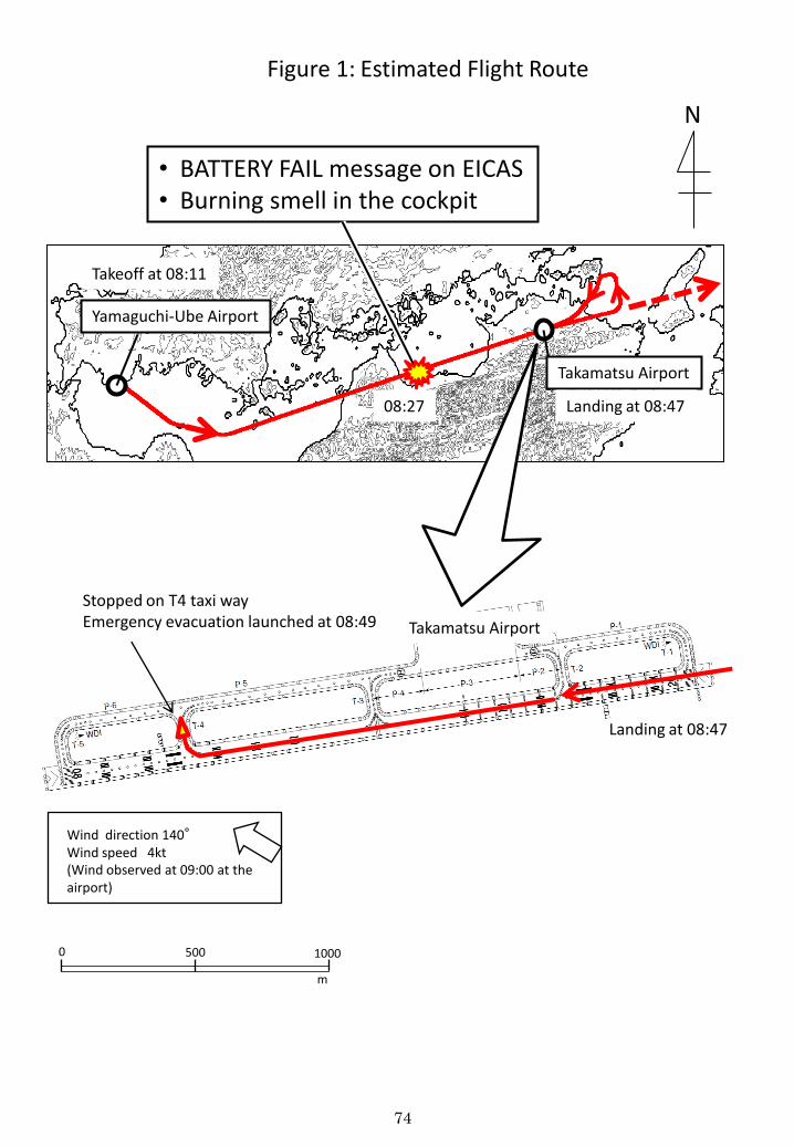
Figure 1: Estimated Flight Route
• BATTERY FAIL message on EICAS • Burning smell in the cockpit
Yamaguchi-Ube Airport
Takeoff at 08:11
08:27
Takamatsu Airport
Landing at 08:47
N
Takamatsu Airport
Landing at 08:47
Stopped on T4 taxi way Emergency evacuation launched at 08:49
Wind direction 140° Wind speed 4kt (Wind observed at 09:00 at the airport)
1000 500 0
m
74
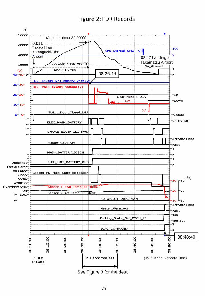
31V
(℃)
11V
(Altitude about 32,000ft)
(ft)
Takeoff from
Yamaguchi-Ube
Ariport
About 16 min
08:11
3V
(V) 08:26:44
08:48:40
Figure 2: FDR Records
08:47 Landing at
Takamatsu Airport
32V
See Figure 3 for the detail
(JST: Japan Standard Time) T: True
F: False
75
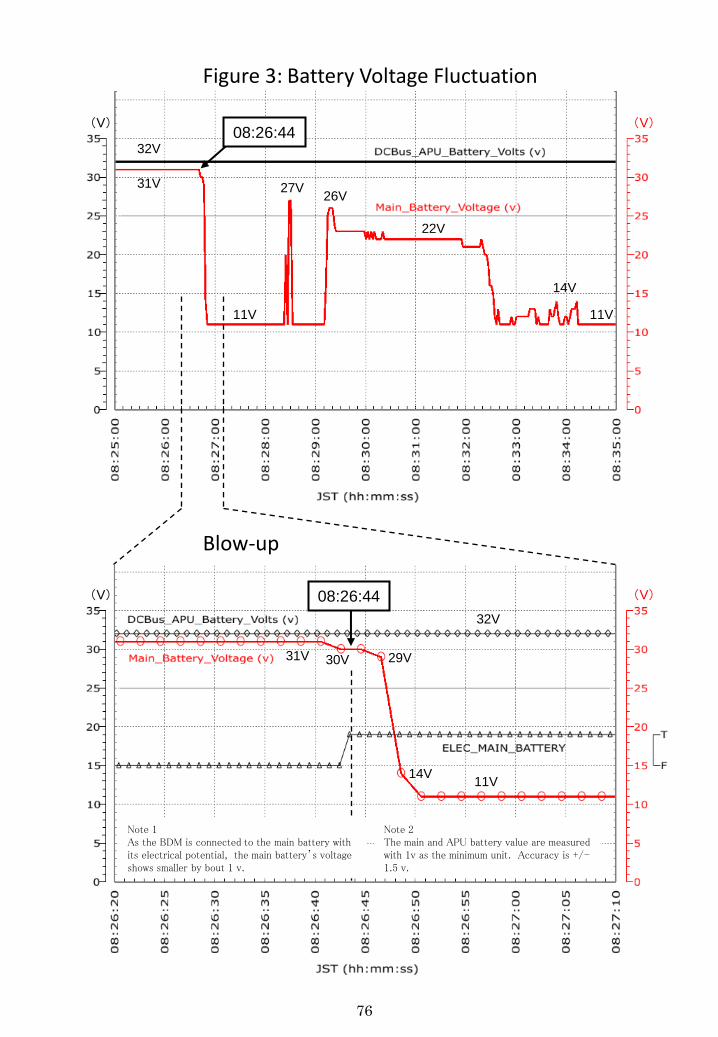
31V
11V 11V
32V
27V 26V
22V
14V
31V
11V
32V
30V 29V
14V
08:26:44
08:26:44
Figure 3: Battery Voltage Fluctuation
Blow-up
(V)
(V)
(V)
(V)
Note 2 The main and APU battery value are measured with 1v as the minimum unit. Accuracy is +/- 1.5 v.
Note 1 As the BDM is connected to the main battery with its electrical potential, the main battery’s voltage shows smaller by bout 1 v.
76
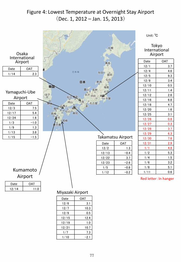
77
Osaka International
Airport
Kumamoto Airport
Miyazaki Airport
Yamaguchi-Ube Airport
Takamatsu Airport
Red letter:In hanger
Figure 4: Lowest Temperature at Overnight Stay Airport (Dec. 1, 2012 – Jan. 15, 2013)
Tokyo International
Airport
Unit: ℃
日付 外気温
12/14 11.0
OAT Date
日付 外気温
12/6 3.1
12/7 10.3
12/9 0.5
12/15 12.4
12/19 1.0
12/21 10.7
1/7 7.3
1/10 -2.1
OAT Date
日付 外気温
12/2 1.3
12/13 -0.4
12/22 3.7
12/23 -2.6
1/5 -0.8
1/12 -0.2
OAT Date
日付 外気温
12/1 3.7
12/4 4.6
12/5 9.3
12/8 3.4
12/10 0.5
12/11 1.4
12/12 2.6
12/16 6.8
12/18 4.7
12/20 1.6
12/25 3.1
12/26 0.8
12/27 0.3
12/28 3.7
12/29 6.3
12/30 7.6
12/31 2.9
1/1 4.8
1/2 5.3
1/4 1.5
1/6 3.2
1/8 5.1
1/11 0.6
OAT Date
日付 外気温
12/3 7.5
12/17 5.4
12/24 1.6
1/3 -1.0
1/9 1.3
1/13 3.8
1/15 -1.5
OAT Date
日付 外気温
1/14 2.3
OAT Date
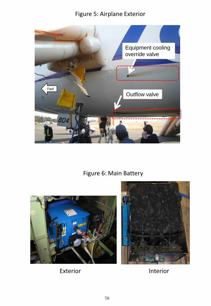
78
Figure 5: Airplane Exterior
Equipment cooling
override valve
Fwd
Outflow valve
Figure 6: Main Battery
Exterior Interior
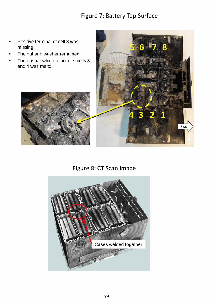
79
• Positive terminal of cell 3 was
missing.
• The nut and washer remained.
• The busbar which connect s cells 3
and 4 was meltd.
Fwd
1 2 3
8 7 6
4
5
Cases welded together
Figure 7: Battery Top Surface
Figure 8: CT Scan Image
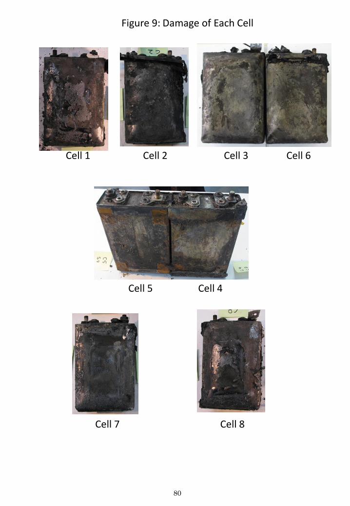
80
Figure 9: Damage of Each Cell
Cell 1 Cell 2 Cell 3
Cell 4 Cell 5
Cell 6
Cell 7 Cell 8
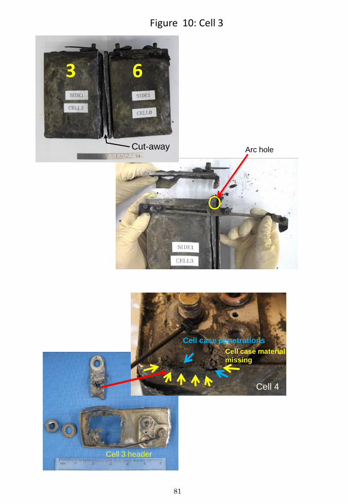
81
Cell case penetrations
Cell case material
missing
Cell 4
Arc hole
3 6
Cut-away
Cell 3 header
Figure 10: Cell 3
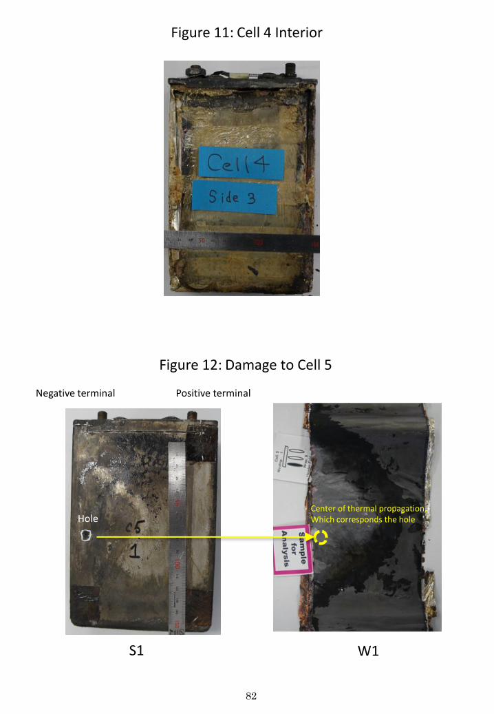
82
セル5
Hole Center of thermal propagation, Which corresponds the hole
Figure 11: Cell 4 Interior
Figure 12: Damage to Cell 5
Positive terminal Negative terminal
W1 S1
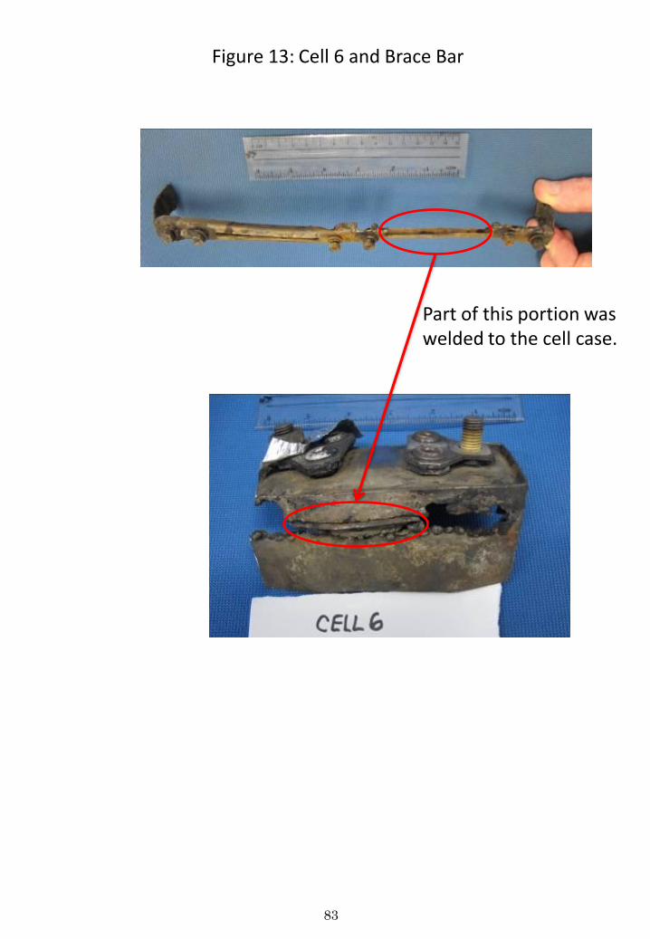
83
Figure 13: Cell 6 and Brace Bar
Part of this portion was welded to the cell case.
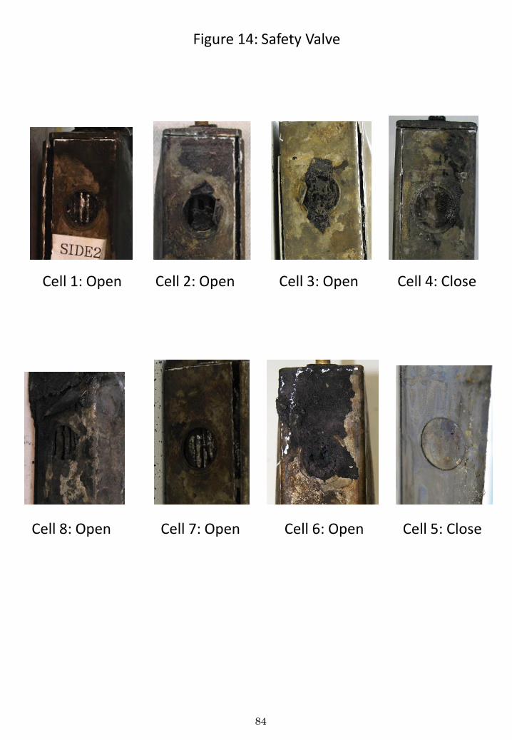
84
Figure 14: Safety Valve
Cell 8: Open Cell 7: Open Cell 6: Open Cell 5: Close
Cell 4: Close Cell 3: Open Cell 2: Open Cell 1: Open
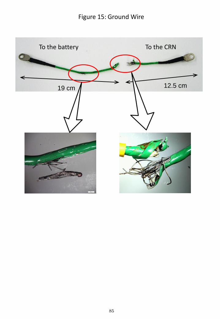
85
19 cm 12.5 cm
Figure 15: Ground Wire
To the battery To the CRN
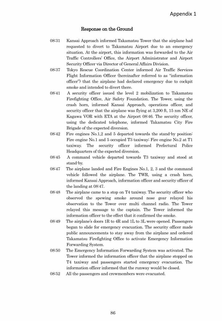
86
Appendix 1
Response on the Ground
08:31 Kansai Approach informed Takamatsu Tower that the airplane had
requested to divert to Takamatsu Airport due to an emergency
situation. At the airport, this information was forwarded to the Air
Traffic Controllers’ Office, the Airport Administrator and Airport
Security Officer via Director of General Affairs Division.
08:37 Tokyo Rescue Coordination Center informed Air Traffic Services
Flight Information Officer (hereinafter referred to as “information
officer”) that the airplane had declared emergency due to cockpit
smoke and intended to divert there.
08:41 A security officer issued the level 2 mobilization to Takamatsu
Firefighting Office, Air Safety Foundation. The Tower, using the
crash horn, informed Kansai Approach, operations officer, and
security officer that the airplane was flying at 3,200 ft, 15 nm NE of
Kagawa VOR with ETA at the Airport 08:46. The security officer,
using the dedicated telephone, informed Takamatsu City Fire
Brigade of the expected diversion.
08:42 Fire engines No.1,2 and 5 departed towards the stand-by position:
Fire engine No.1 and 5 occupied T3 taxiway; Fire engine No.2 at T1
taxiway. The security officer informed Prefectural Police
Headquarters of the expected diversion.
08:45 A command vehicle departed towards T3 taxiway and stood at
stand-by.
08:47 The airplane landed and Fire Engines No.1, 2, 3 and the command
vehicle followed the airplane. The TWR, using a crash horn,
informed Kansai Approach, information officer and security officer of
the landing at 08:47.
08:48 The airplane came to a stop on T4 taxiway. The security officer who
observed the spewing smoke around nose gear relayed his
observation to the Tower over multi channel radio. The Tower
relayed this message to the captain. The Tower informed the
information officer to the effect that it confirmed the smoke.
08:49 The airplane’s doors 1R to 4R and 1L to 3L were opened. Passengers
began to slide for emergency evacuation. The security officer made
public announcements to stay away from the airplane and ordered
Takamatsu Firefighting Office to activate Emergency Information
Forwarding System.
08:50 The Emergency Information Forwarding System was activated. The
Tower informed the information officer that the airplane stopped on
T4 taxiway and passengers started emergency evacuation. The
information officer informed that the runway would be closed.
08:52 All the passengers and crewmembers were evacuated.
87
08:56 The security officer asked the PIC to check for the number of
occupants and their safety. AT 09:05 he received the verbal report
from the PIC.
09:05 Airplane occupants started to walk towards the terminal building.
09:25 The security officer, ANA mechanics, City Fire Brigade personnel
started site inspection.
09:35 The City Fire Brigade informed the information officer that a male
passenger who suffered hip bruise (light injury) had been taken to
the city hospital.
09:49 The City Fire Brigade informed the information officer that the
airplane was confirmed safe.
10:04 Vehicles from Takamatsu City Fire Brigade began leaving the site
and at 10:25 all of them left the site.
10:34 The Security officer ordered the fire engines’ withdrawal from the
site and this completed at 10:40.
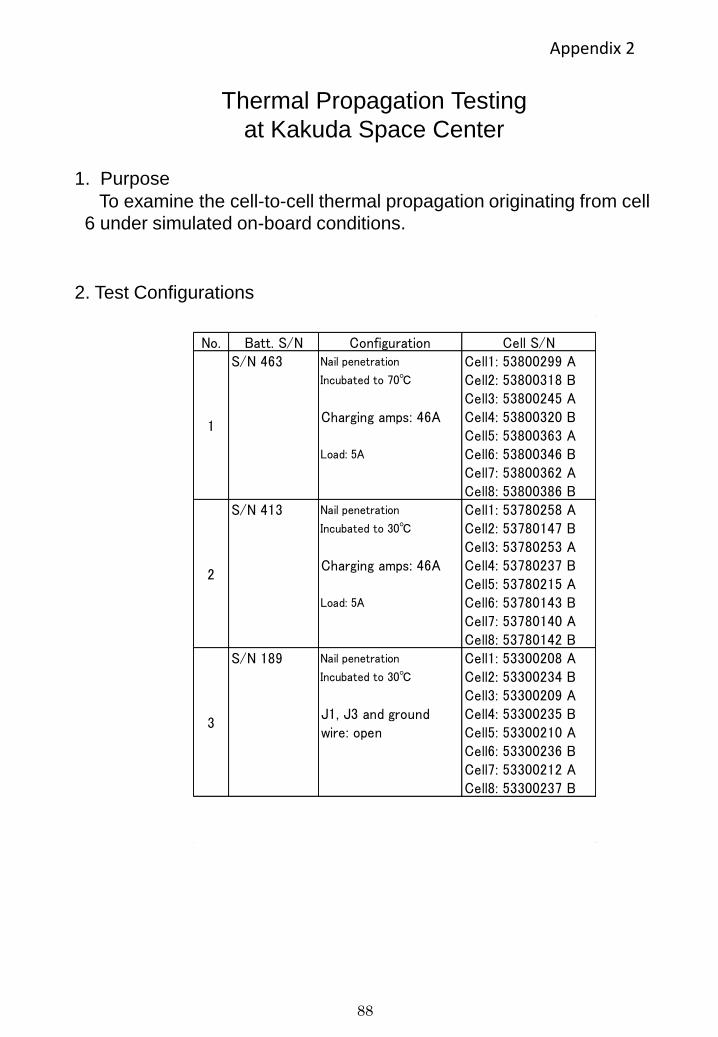
88
Thermal Propagation Testing
at Kakuda Space Center
1. Purpose
To examine the cell-to-cell thermal propagation originating from cell
6 under simulated on-board conditions.
No. Batt. S/N Configuration Cell S/NS/N 463 Nail penetration Cell1: 53800299 A
Incubated to 70℃ Cell2: 53800318 B Cell3: 53800245 A
Charging amps: 46A Cell4: 53800320 B Cell5: 53800363 A
Load: 5A Cell6: 53800346 B Cell7: 53800362 A Cell8: 53800386 B
S/N 413 Nail penetration Cell1: 53780258 A Incubated to 30℃ Cell2: 53780147 B
Cell3: 53780253 A Charging amps: 46A Cell4: 53780237 B
Cell5: 53780215 A Load: 5A Cell6: 53780143 B
Cell7: 53780140 A Cell8: 53780142 B
S/N 189 Nail penetration Cell1: 53300208 A Incubated to 30℃ Cell2: 53300234 B
Cell3: 53300209 A J1, J3 and ground Cell4: 53300235 B wire: open Cell5: 53300210 A
Cell6: 53300236 B Cell7: 53300212 A Cell8: 53300237 B
1
2
3
2. Test Configurations
Appendix 2
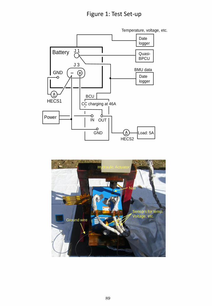
89
Sensors for temp.
Voltage, etc.
Nail
Ground wire
Hydraulic Actuator
J 1
J 3
GND
Battery
IN OUT
GND
Power
BCU
CC charging at 46A
HECS2
HECS1
Load: 5AA
Datelogger
BMU data
Temperature, voltage, etc.
A
Quasi-BPCU
Datelogger
Figure 1: Test Set-up
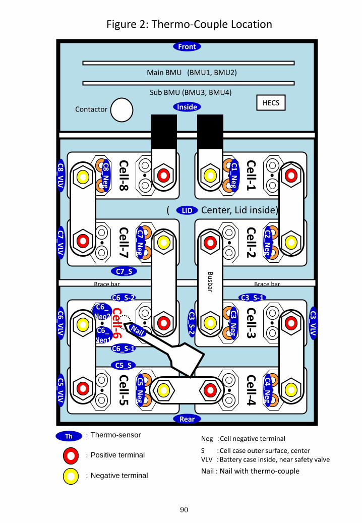
90
:Thermo-sensor Th
:Positive terminal
:Negative terminal
Neg :Cell negative terminal
S :Cell case outer surface, center VLV :Battery case inside, near safety valve
C4
_Neg
C3
_Neg
C3_S-1
C2
_Neg
C5
_Ne
g
C5_S
C6_S-1
C6_ Neg1
C6_S-2
C7_S
C7
_Ne
g
C1
_Neg
C8
_Neg
C3
_S-2
C3
_VLV
C6
_VLV
C
7_V
LV
C8
_VLV
C
5_V
LV
Rear
Front
Inside
( Center, Lid inside) LID
Ce
ll-1
Ce
ll-2
Ce
ll-3
Ce
ll-4
Ce
ll-5
Ce
ll-6
Ce
ll-7
Ce
ll-8
C6_ Neg2
Brace bar Brace bar
Bu
sbar
Contactor
Main BMU (BMU1, BMU2)
Sub BMU (BMU3, BMU4)
HECS
Figure 2: Thermo-Couple Location
Nail : Nail with thermo-couple
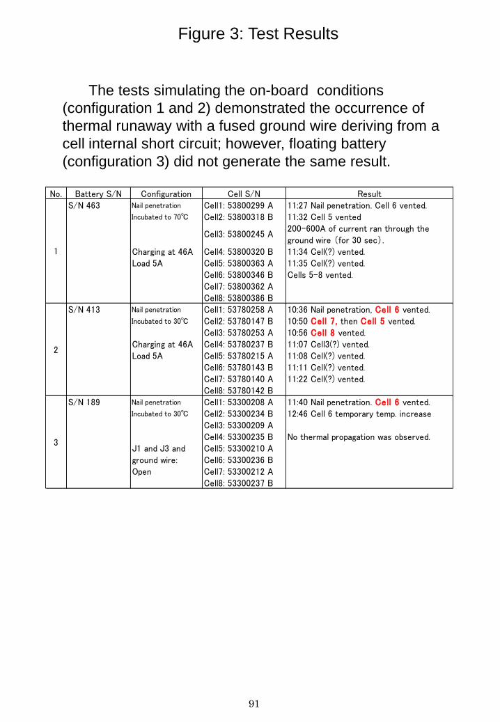
91
Figure 3: Test Results
The tests simulating the on-board conditions
(configuration 1 and 2) demonstrated the occurrence of
thermal runaway with a fused ground wire deriving from a
cell internal short circuit; however, floating battery
(configuration 3) did not generate the same result.
No. Battery S/N Configuration Cell S/N ResultS/N 463 Nail penetration Cell1: 53800299 A 11:27 Nail penetration. Cell 6 vented.
Incubated to 70℃ Cell2: 53800318 B 11:32 Cell 5 vented
Cell3: 53800245 A 200-600A of current ran through theground wire (for 30 sec).
Charging at 46A Cell4: 53800320 B 11:34 Cell(?) vented.Load 5A Cell5: 53800363 A 11:35 Cell(?) vented.
Cell6: 53800346 B Cells 5-8 vented.Cell7: 53800362 A Cell8: 53800386 B
S/N 413 Nail penetration Cell1: 53780258 A 10:36 Nail penetration, Cell 6 vented.Incubated to 30℃ Cell2: 53780147 B 10:50 Cell 7, then Cell 5 vented.
Cell3: 53780253 A 10:56 Cell 8 vented.Charging at 46A Cell4: 53780237 B 11:07 Cell3(?) vented. Load 5A Cell5: 53780215 A 11:08 Cell(?) vented.
Cell6: 53780143 B 11:11 Cell(?) vented.Cell7: 53780140 A 11:22 Cell(?) vented.Cell8: 53780142 B
S/N 189 Nail penetration Cell1: 53300208 A 11:40 Nail penetration. Cell 6 vented.Incubated to 30℃ Cell2: 53300234 B 12:46 Cell 6 temporary temp. increase
Cell3: 53300209 A Cell4: 53300235 B No thermal propagation was observed.
J1 and J3 and Cell5: 53300210 A ground wire: Cell6: 53300236 B Open Cell7: 53300212 A
Cell8: 53300237 B
1
2
3
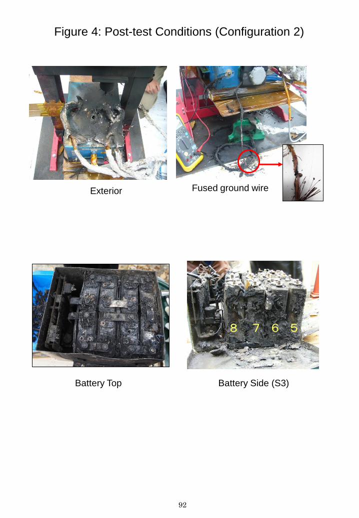
92
Figure 4: Post-test Conditions (Configuration 2)
Exterior Fused ground wire
Battery Top Battery Side (S3)
5 6 7 8
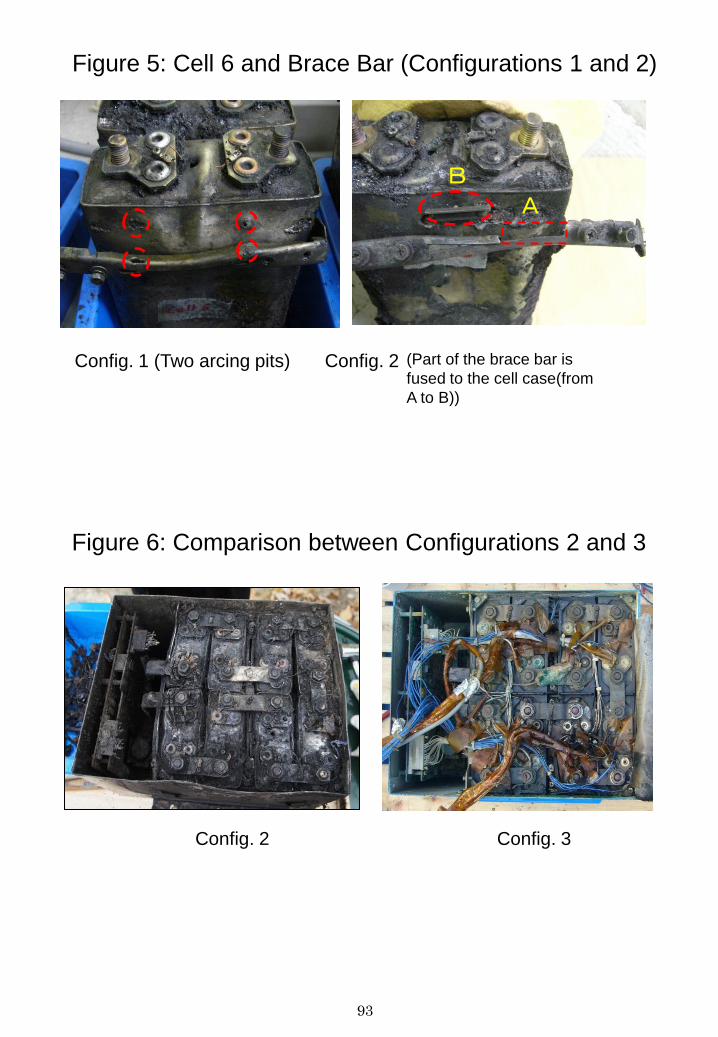
93
Figure 5: Cell 6 and Brace Bar (Configurations 1 and 2)
Config. 1 (Two arcing pits) Config. 2 (Part of the brace bar is
fused to the cell case(from
A to B))
A
B
Figure 6: Comparison between Configurations 2 and 3
Config. 3 Config. 2
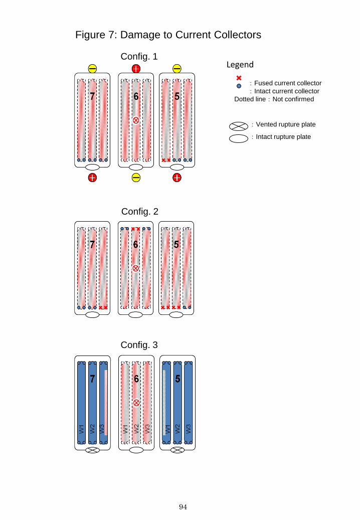
94
Figure 7: Damage to Current Collectors
:Fused current collector
:Intact current collector
Dotted line:Not confirmed
:Vented rupture plate
:Intact rupture plate
Legend Config. 1
Config. 3
Config. 2
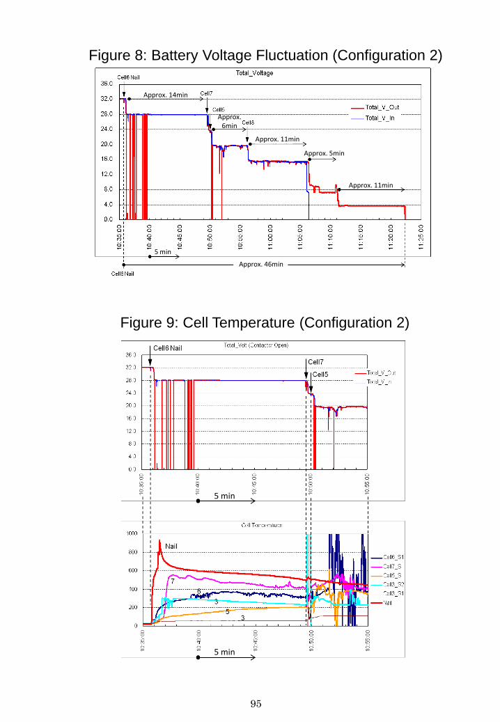
95
Figure 8: Battery Voltage Fluctuation (Configuration 2)
Figure 9: Cell Temperature (Configuration 2)
5 min
5 min
5 min
Approx. 46min
Approx. 11min
Approx. 5min
Approx. 11min
Approx. 14min
Approx. 6min
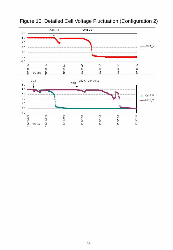
96
Figure 10: Detailed Cell Voltage Fluctuation (Configuration 2)
10 sec
10 sec
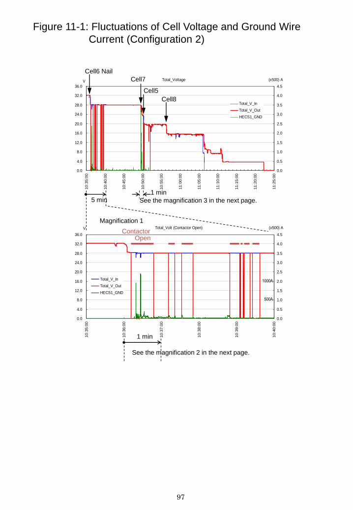
97
Total_Voltage
0.0
4.0
8.0
12.0
16.0
20.0
24.0
28.0
32.0
36.010:3
5:0
0
10:4
0:0
0
10:4
5:0
0
10:5
0:0
0
10:5
5:0
0
11:0
0:0
0
11:0
5:0
0
11:1
0:0
0
11:1
5:0
0
11:2
0:0
0
11:2
5:0
0
V
0.0
0.5
1.0
1.5
2.0
2.5
3.0
3.5
4.0
4.5
(x500) A
Total_V_In
Total_V_Out
HECS1_GND
Total_Volt (Contactor Open)
0.0
4.0
8.0
12.0
16.0
20.0
24.0
28.0
32.0
36.0
10:3
5:0
0
10:3
6:0
0
10:3
7:0
0
10:3
8:0
0
10:3
9:0
0
10:4
0:0
0
V
0.0
0.5
1.0
1.5
2.0
2.5
3.0
3.5
4.0
4.5
(x500) A
Total_V_In
Total_V_Out
HECS1_GND
Magnification 1
Cell6 Nail
Cell7
Cell5
Cell8
5 min
1 min
Contactor Open
1000A
500A
See the magnification 2 in the next page.
1 min
See the magnification 3 in the next page.
Figure 11-1: Fluctuations of Cell Voltage and Ground Wire
Current (Configuration 2)
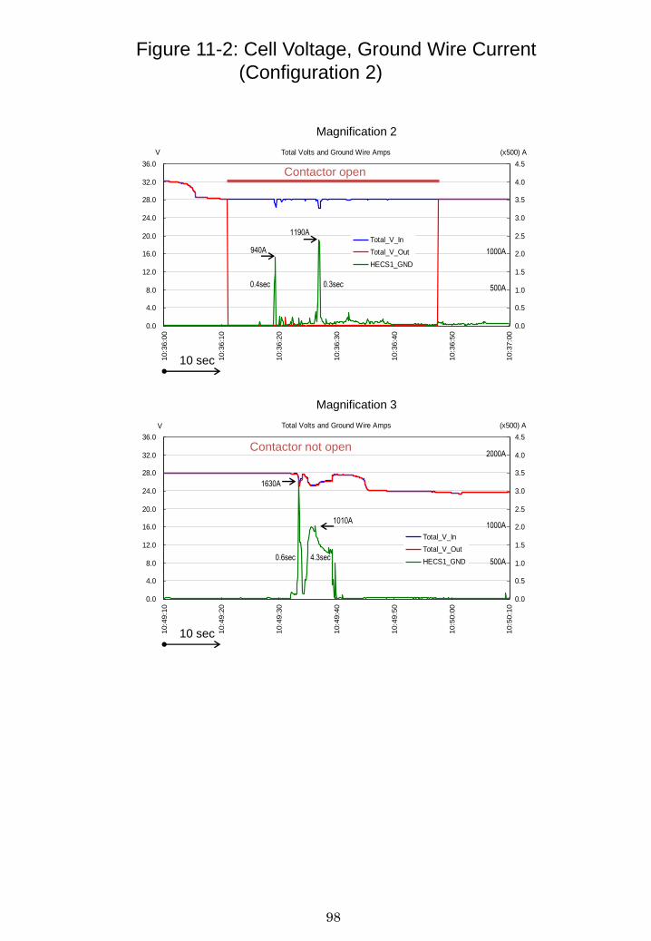
98
Total Volts and Ground Wire Amps
0.0
4.0
8.0
12.0
16.0
20.0
24.0
28.0
32.0
36.010:3
6:0
0
10:3
6:1
0
10:3
6:2
0
10:3
6:3
0
10:3
6:4
0
10:3
6:5
0
10:3
7:0
0
V
0.0
0.5
1.0
1.5
2.0
2.5
3.0
3.5
4.0
4.5
(x500) A
Total_V_In
Total_V_Out
HECS1_GND
Total Volts and Ground Wire Amps
0.0
4.0
8.0
12.0
16.0
20.0
24.0
28.0
32.0
36.0
10:4
9:1
0
10:4
9:2
0
10:4
9:3
0
10:4
9:4
0
10:4
9:5
0
10:5
0:0
0
10:5
0:1
0
V
0.0
0.5
1.0
1.5
2.0
2.5
3.0
3.5
4.0
4.5
(x500) A
Total_V_In
Total_V_Out
HECS1_GND
Magnification 2
Magnification 3
Contactor not open
10 sec
1000A
500A
Contactor open
10 sec
1190A
940A
0.3sec 0.4sec
1000A
500A
2000A
1630A
1010A
0.6sec 4.3sec
Figure 11-2: Cell Voltage, Ground Wire Current
(Configuration 2)
99
Comments from France
Appendix 3
100
101