Embed Size (px)
Citation preview
NOT MEASUREMENTSENSITIVE
MIL-HDBK-1530A(USAF)24 JANUARY 2002
SUPERSEDINGMIL-HDBK-1530(USAF)31 OCTOBER 1996
DEPARTMENT OF DEFENSE HANDBOOK
AIRCRAFT STRUCTURAL INTEGRITY PROGRAMGENERAL GUIDELINES FOR
THIS HANDBOOK IS FOR GUIDANCE ONLY.DO NOT CITE THIS DOCUMENT AS A REQUIREMENT.
AMSC N/A FSC 15GP
DISTRIBUTION STATEMENT A. Approved for public release; distribution is unlimited.
Downloaded from http://www.everyspec.com
MIL-HDBK-1530A(USAF)
ii
FOREWORD
1. This handbook is approved for use by the Department of the Air Force and is available for use by allDepartments and Agencies of the Department of Defense.
2. This handbook is for guidance only. This handbook cannot be cited as a requirement. If it is, thecontractor does not have to comply.
3. This handbook provides guidance for programmatic tasks for the conceptual definition, development,acquisition, maintenance, and modification of the primary and secondary structures of crewed and unmanned flightvehicles and external stores, to ensure their structural integrity while affordability of these Air Force systems ismaintained throughout their period of use. Structural deficiencies must be identified and corrected as early aspossible to minimize repairs, modifications, and life cycle costs while cost and schedule risks are managed. TheAircraft Structural Integrity Program (ASIP) consists of a series of disciplined, time-phased actions; procedures;analyses; tests; etc.; which, when developed and applied in accordance with the guidance of this handbook; willensure reliable, affordable, and supportable flight vehicle primary and secondary structures, thus contributing to theenhancement of total systems mission effectiveness and operational suitability while minimizing cost and schedulerisks.
4. This handbook is available to promote implementation and provide guidance which concernsimplementation of Air Force Policy Directive (AFPD) 63-10 and Air Force Instruction (AFI) 63-1001. Bothdocuments, AFPD 63-10 and AFI 63-1001, contain policy directives which ensure the safe operation of theU.S. Air Force airframe structures. These constraints are not repeated in higher-level policy (e.g., DoD-5000 series)and have no commercial equivalent (e.g., FAA regulations). In addition, these peculiar ASIP constraints evolvefrom durability considerations and individual tracking and data gathering which are part of AFI 63-1001.
5. Beneficial comments (recommendations, additions, deletions) and any pertinent data which may be of usein improving this document should be addressed to: ASC/ENOI, 2530 LOOP ROAD WEST, WRIGHT-PATTERSON AFB OH 45433-7101; by use of the Standardization Document Improvement Proposal (DD Form1426) that appears at the end of this document, or by letter.
Downloaded from http://www.everyspec.com
MIL-HDBK-1530A(USAF)
iii
CONTENTSPARAGRAPH PAGE
1. SCOPE .........................................................................................................................................11.1 Scope............................................................................................................................................11.1.1 Application...................................................................................................................................11.1.2 Tailoring.......................................................................................................................................12. APPLICABLE DOCUMENTS....................................................................................................12.1 General .........................................................................................................................................12.2 Government documents ...............................................................................................................12.2.1 Specifications, standards, and handbooks....................................................................................12.2.2 Other Government documents, drawings, and publications.........................................................22.3 Non-Government publications .....................................................................................................32.4 Order of precedence .....................................................................................................................33. DEFINITIONS.............................................................................................................................33.1 Damage tolerance.........................................................................................................................33.2 Design service goal ......................................................................................................................33.3 Durability .....................................................................................................................................33.4 Economic life ...............................................................................................................................33.5 Fail-safe........................................................................................................................................33.6 Initial quality ................................................................................................................................33.7 Multiple load path ........................................................................................................................33.8 Onset of widespread fatigue damage ...........................................................................................43.9 Principal structural element (PSE) ...............................................................................................43.10 Single load path............................................................................................................................43.11 Structural operating mechanisms .................................................................................................44. GENERAL GUIDELINES ..........................................................................................................44.1 ASIP goals ...................................................................................................................................44.2 Primary tasks................................................................................................................................45. DETAIL GUIDELINES ..............................................................................................................55.1 Design information (Task I).........................................................................................................55.1.1 ASIP master plan .........................................................................................................................55.1.2 Structural design criteria ..............................................................................................................55.1.2.1 Damage tolerance and durability design criteria..........................................................................55.1.2.1.1 Damage tolerance.........................................................................................................................65.1.2.1.2 Durability .....................................................................................................................................65.1.2.1.3 Corrosion control and prevention ................................................................................................65.1.2.2 Battle damage criteria ..................................................................................................................65.1.2.3 Repairability.................................................................................................................................65.1.3 Durability and damage tolerance control .....................................................................................65.1.4 Selection of materials, processes, and joining methods ...............................................................75.1.4.1 Structural materials, processes and joining methods selection criteria ........................................75.1.5 Design service goal and design usage..........................................................................................75.1.6 Nondestructive testing and inspection (NDT/I) ...........................................................................75.2 Design analyses and development tests (Task II) ........................................................................75.2.1 Material and joint allowables .......................................................................................................75.2.2 Loads analysis ..............................................................................................................................75.2.3 Design service loads spectra ........................................................................................................75.2.4 Design chemical/thermal environment spectra ............................................................................85.2.5 Stress analysis ..............................................................................................................................85.2.6 Damage tolerance analysis ...........................................................................................................85.2.7 Durability analysis .......................................................................................................................85.2.8 Aeroacoustic durability analysis ..................................................................................................85.2.9 Vibration analysis ........................................................................................................................85.2.10 Flutter analysis .............................................................................................................................9
Downloaded from http://www.everyspec.com
MIL-HDBK-1530A(USAF)
iv
CONTENTSPARAGRAPH PAGE
5.2.11 Mass properties analysis ..............................................................................................................95.2.12 Nuclear weapons effects analyses ................................................................................................95.2.13 Nonnuclear weapons effects analysis...........................................................................................95.2.14 Design development tests.............................................................................................................95.3 Full-scale testing (Task III)..........................................................................................................95.3.1 Static tests ....................................................................................................................................95.3.1.1 Schedule requirement...................................................................................................................105.3.2 Durability tests .............................................................................................................................105.3.2.1 Selection of test articles ...............................................................................................................105.3.2.2 Test scheduling ............................................................................................................................105.3.2.3 Inspections ...................................................................................................................................115.3.2.4 Test duration ................................................................................................................................115.3.3 Damage tolerance tests.................................................................................................................115.3.4 Flight and ground operations tests ...............................................................................................115.3.4.1 Flight and ground loads survey....................................................................................................115.3.4.2 Dynamic response tests ................................................................................................................115.3.5 Aeroacoustic durability tests ........................................................................................................125.3.6 Flight vibration tests.....................................................................................................................125.3.7 Flutter tests...................................................................................................................................125.3.7.1 Ground vibration tests and aeroservoelastic ground tests ............................................................125.3.7.2 Structural rigidity tests .................................................................................................................125.3.7.3 Flight flutter tests .........................................................................................................................125.3.8 Mass properties testing.................................................................................................................125.3.9 Interpretation and evaluation of test results .................................................................................125.4 Force management data package (Task IV) .................................................................................125.4.1 Final analyses...............................................................................................................................135.4.1.1 Initial update of analyses..............................................................................................................135.4.1.2 Final update of analyses ...............................................................................................................135.4.1.3 Development of inspection and repair criteria .............................................................................135.4.2 Strength summary ........................................................................................................................135.4.3 Force structural maintenance documentation...............................................................................135.4.4 Loads/environment spectra survey...............................................................................................145.4.4.1 Data processing provisions ..........................................................................................................145.4.4.2 Analysis of data and development of baseline operational spectra..............................................145.4.5 Individual air vehicle tracking program.......................................................................................145.4.5.1 Tracking analysis method ............................................................................................................145.4.5.2 Data acquisition provisions ..........................................................................................................145.5 Force management (Task V) ........................................................................................................145.5.1 Loads/environment spectra survey...............................................................................................155.5.2 Individual air vehicle tracking data..............................................................................................155.5.3 Individual air vehicle maintenance times.....................................................................................155.5.4 Structural maintenance records ....................................................................................................165.5.5 Weight and balance records .........................................................................................................166. NOTES.........................................................................................................................................166.1 Intended use .................................................................................................................................166.2 Supersession data .........................................................................................................................176.3 Data requirements ........................................................................................................................166.4 Subject term (key word) listing....................................................................................................176.5 Changes from previous issue .......................................................................................................17
Downloaded from http://www.everyspec.com
MIL-HDBK-1530A(USAF)
v/vi
CONTENTSPARAGRAPH PAGE
TABLE
I. USAF Aircraft Structural Integrity Program tasks.......................................................................18
FIGURES
1. Aircraft Structural Integrity Program - Part 1 ..............................................................................192. Aircraft Structural Integrity Program - Part 2 ..............................................................................203. Aircraft Structural Integrity Program - Part 3 ..............................................................................224. Aircraft Structural Integrity Program - Part 4 ..............................................................................22
APPENDICES
APPENDIX A: ADDITIONAL GUIDANCE FOR NEW, OFF-THE- SHELF AIR VEHICLESA.1 Structural qualification.................................................................................................................23A.1.1 Performance requirements. ..........................................................................................................23A.1.2 Service goal concept ....................................................................................................................23A.1.3 Preliminary structural evaluation .................................................................................................23A.1.4 Additional analyses. .....................................................................................................................24A.1.5 Risk assessment............................................................................................................................24A.1.6 New or modified structure ...........................................................................................................24A.1.7 Airframe condition.......................................................................................................................24
APPENDIX B: ADDITIONAL GUIDANCE FOR AGING AIR VEHICLESB.1 Aging air vehicles ........................................................................................................................25B.1.1 Operations beyond the design service goal of the air vehicle ......................................................25B.1.2 Corrosion......................................................................................................................................25B.1.3 Widespread fatigue damage .........................................................................................................25B.1.4 Repairs .........................................................................................................................................25
Downloaded from http://www.everyspec.com
MIL-HDBK-1530A(USAF)
THIS PAGE INTENTIONALLY LEFT BLANK.
Downloaded from http://www.everyspec.com
MIL-HDBK-1530A(USAF)
1
1. SCOPE
1.1 Scope. This handbook contains general guidelines for the U.S. Air Force Aircraft Structural IntegrityProgram (ASIP). These guidelines describe the processes proven successful in achieving structural integrity ofUSAF air vehicles while the cost of ownership is minimized, and cost and schedule risks managed through a seriesof disciplined, time-phased tasks. This handbook is for guidance only. This handbook cannot be cited as arequirement. If it is, the contractor does not have to comply.
1.1.1 Application. This handbook provides guidance to contractors in the development of an airframe fora particular weapon or support system and to government personnel in managing the development, production, andoperational support throughout the life cycle or a particular structures program and air vehicle system, as follows:
a. Type of air vehicle. This handbook is directly applicable to manned air vehicles which have fixed oradjustable fixed wings and to those portions of manned helicopter and Vertical/Short Takeoff and Landing(V/STOL) air vehicles which have similar structural characteristics. Helicopter-type power transmission systems—including lifting and control rotors and other dynamic machinery; power generators, engines, and propulsionsystems—are not covered. For unmanned vehicles, some guidelines of this handbook are generally not applicablecommensurate with sufficient structural safety and durability to meet the intended use of the airframe.
b. Type of program. This handbook should be applied to new air vehicle systems, to air vehicle systemsprocured by the U.S. Air Force but developed under the auspices of other government agencies or departments(such as the Federal Aviation Administration or United States Navy), and air vehicles modified or directed to newmissions. Procurement of off-the-shelf, new or used air vehicles for military use presents somewhat differentproblems than procurement of air vehicles developed under the auspices of the military services. Although theASIP process still applies, additional tailoring is needed to optimize these programs. Appendix A providesadditional guidance for procurement of off-the-shelf air vehicles. Appendix B provides additional guidance foraging air vehicle programs.
c. Type of structure. This handbook should be applied to metallic and nonmetallic structures.
1.1.2 Tailoring. This handbook may not need to be invoked on a blanket basis. It should be tailored to thespecific program, with each guideline assessed in terms of need. The degree of applicability of the various portionsof this handbook will vary among programs.
2. APPLICABLE DOCUMENTS
2.1 General. The documents listed below are not necessarily all of the documents referenced herein, but arethose needed to understand fully the information provided by this handbook.
2.2 Government documents
2.2.1 Specifications, standards, and handbooks. The following specifications, standards, and handbooksform a part of this document to the extent specified herein. Unless otherwise specified, the issues of thesedocuments are those listed in the latest issue of the Department of Defense Index of Specifications and Standards(DoDISS) and supplement thereto.
Downloaded from http://www.everyspec.com
MIL-HDBK-1530A(USAF)
2
SPECIFICATIONS
Department of Defense
JSSG-2006 Aircraft Structures
HANDBOOKS
Department of Defense
MIL-HDBK-5 Metallic Materials and Elements for Aerospace Vehicle StructuresMIL-HDBK-17 Plastics for Flight VehiclesMIL-HDBK-23 Structural Sandwich Composites (cancelled)MIL-HDBK-6870 Inspection Program Requirements, Nondestructive, for Aircraft
and Missile Materials and Parts
(Unless otherwise indicated, copies of the above specifications, standards, and handbooks are available fromthe Standardization Document Order Desk, 700 Robbins Avenue, Bldg 4D, Philadelphia PA 19111-5094;[215] 697-2179; http://assist.daps.mil. MIL-HDBK-23 is listed for reference; it has been cancelled and copies arenot available.)
2.2.2 Other Government documents, drawings, and publications. The following other Governmentdocuments, drawings, and publications form a part of this document to the extent specified herein.
U.S. AIR FORCE DIRECTIVES/INSTRUCTIONS
Air Force Policy DirectiveAFPD 21-1
Managing Aerospace Equipment Maintenance
Air Force Policy DirectiveAFPD 63-10
Aircraft Structural Integrity
Air Force InstructionAFI 21-105
Aerospace Equipment Structural Maintenance
Air Force InstructionAFI 63-1001
Aircraft Structural Integrity Program
Air Force Materiel Command InstructionAFMCI 21-102
Analytical Condition Inspection (ACI) Programs
(Copies of Directives and Instructions are available from the US Air Force Publications Distribution Center,2800 Eastern Blvd, Baltimore MD 21220-2898; [410] 687-3330; http://afpubs.hq.af.mil.)
U.S. AIR FORCE TECHNICAL ORDERS
T.O. 1-1B-40 Weight and Balance DataT.O. 1-1B-50 Basic Technical Order for USAF Aircraft Weight and Balance
(Copies of T.O.s are available from Oklahoma City Air Logistics Center (OC-ALC/TILUB), 7851 Arnold StSte 209; Tinker AFB OK 73145-9147; [405] 736-5468; http://wwwmil.robins.af.mil/imweb/IMP.htm.)
TECHNICAL REPORTS
WL-TR-94-40152/3/4/5/6 Damage Tolerance Design Handbook
(Copies of TRs are available from the Defense Technical Information Center [DTIC], 8725 John J. KingmanRoad, Suite 0944, Fort Belvoir VA 22060-6218; [703] 767-8274; http://www.dtic.mil.)
Downloaded from http://www.everyspec.com
MIL-HDBK-1530A(USAF)
3
2.3 Non-Government publications. The following documents form a part of this document to the extentspecified herein. Unless otherwise specified, the issues of the documents which are DoD adopted are those listed inthe latest issue of the DoDISS, and supplement thereto.
MCIC-HDBK-01 Damage Tolerance Design Handbook
(Copies are available from Metals and Ceramics Information Center, Battelle Memorial Institute, 505 KingAvenue, Columbus OH 43201-2681.)
RP #7 Society of Allied Weight Engineers
(Copies are available from Society of Allied Weight Engineers, P O Box 60024, Terminal Annex, Los AngelesCA 90060-0024.)
2.4 Order of precedence. In the event of a conflict between the text of this document and the references citedherein, the text of this document takes precedence. Nothing in this document, however, supersedes applicable lawsand regulations unless a specific exemption has been obtained.
3. DEFINITIONS
3.1 Damage tolerance. Damage tolerance is the attribute of a structure that permits it to retain its requiredresidual strength for a period of unrepaired usage after the structure has sustained prescribed levels of fatigue,corrosion, and accidental or discrete source damage such as (a) unstable propagation of fatigue cracks, (b) unstablepropagation of initial or service induced damage, and/or (c) impact damage from a discrete source.
3.2 Design service goal. The design service goal is the period of time (in flight cycles/hours) established atdesign during which the structure will be reasonably free from significant structural degradation.
3.3 Durability. Durability is the ability of the airframe to resist cracking (including stress corrosion andhydrogen-induced cracking), corrosion, thermal degradation, delamination, wear, and the effects of foreign objectdamage for a prescribed period of time.
3.4 Economic life. This is the operational service period during which there is no significant departure fromthe cost burden associated with the Force Structural Maintenance Plan for a newly-manufactured air vehicles, basedon an evaluation of data developed during full-scale development. The economic life is indicated by the results ofthe durability test program; i.e., test performance interpretation and evaluation in accordance with JSSG-2006. Theeconomic life should be evaluated with the incorporation of U.S. Air Force-approved and committed production orretrofit changes and the supporting application of the force structural inspection and maintenance documentation inaccordance with this handbook. In general, production or retrofit changes will be incorporated to correct localdesign and manufacturing deficiencies disclosed by test. It will be assumed that the economic life of the test articlehas been attained with the occurrence of fatigue cracking which could be uneconomical to repair and, if notrepaired, could cause functional problems which affect operational readiness. This may sometimes be characterizedby a rapid increase in the number of damage locations or repair costs as a function of cyclic test time.
3.5 Fail-safe. Fail-safe is that attribute of the structure that permits it to retain its required residual strength fora period of unrepaired usage after the failure or partial failure of a Principal Structural Element (PSE).
3.6 Initial quality. Initial quality is a measure of the condition of the airframe relative to flaws, defects, orother discrepancies in the basic materials or introduced during manufacture of the airframe.
3.7 Multiple load path. Multiple load path is identified with redundant structures in which the applied loadswould be safely distributed to other load-carrying members in the event of failure of individual elements.
Downloaded from http://www.everyspec.com
MIL-HDBK-1530A(USAF)
4
3.8 Onset of widespread fatigue damage. Onset of widespread fatigue damage in a structure is characterizedby the simultaneous presence of cracks at multiple structural details which are of sufficient size and density wherebythe structure will no longer meet its damage tolerance requirement (e.g., maintaining required residual strength afterpartial structural failure).
3.9 Principal structural element (PSE). A PSE is an element of structure which contributes significantly tocarrying flight, ground, and pressurization loads, and whose integrity is essential to maintenance of the overallstructural integrity of the air vehicle.
3.10 Single load path. Single load path is where the applied loads are eventually distributed through a singlemember, the failure of which would result in the loss of the structural capability to carry the applied loads.
3.11 Structural operating mechanisms. Structural operating mechanisms are those operating, articulating,and control mechanisms which transmit structural forces during actuation and movement of structural surfaces andelements.
4. GENERAL GUIDELINES
4.1 ASIP goals. The effectiveness of any military force depends in part on the operational readiness ofweapon systems. One major item of an air vehicle system that affects its operational readiness is the condition ofthe structure. The complete structure, herein referred to as “the airframe,” includes the fuselage, wing, empennage,landing gear, control systems and surfaces, engine section, nacelle, air induction, weapon mount, engine mounts,structural operating mechanisms, and other components as described in the contract specification. The capabilities,condition, and operational limitations of the airframe of each air vehicle weapon and support system must beestablished to maintain operational readiness. Potential structural or material problems must be identified early inthe life-cycle to minimize their impact on the operational force, and a preventive maintenance program must bedetermined to provide for the orderly scheduling of inspections and replacement or repair of life-limited elements ofthe airframe. The overall program to provide USAF air vehicles with the required airframe structural characteristicsis referred to as the Aircraft Structural Integrity Program, or “ASIP.” The primary purposes of the ASIP are to:
a. establish, evaluate, and substantiate the structural integrity (airframe strength, rigidity, damage tolerance,and durability) of air vehicle structures;
b. acquire, evaluate, and apply operational usage data to provide a continual update of the structuralintegrity of operational air vehicles;
c. provide quantitative information for decisions on force structure planning, inspection, modificationpriorities, and relate operational and support decisions; and
d. provide a basis to improve structural criteria and methods of design, evaluation, and substantiation forfuture air vehicle systems and modifications.
4.2 Primary tasks. ASIP consists of the following five, interrelated functional tasks as delineated in table Iand on figures 1, 2, 3, and 4:
a. Task I (design information). Task I is development of those criteria which must be applied during designso the overall program goals will be met.
b. Task II (design analysis and development tests). Task II is development of the design environment inwhich the airframe must operate and the response of the airframe to the design environment.
c. Task III (full-scale testing). Task III is flight and laboratory tests of the airframe to assist indetermination of the structural adequacy of the analysis and design.
Downloaded from http://www.everyspec.com
MIL-HDBK-1530A(USAF)
5
d. Task IV (force management data package). Task IV is the generation of data required to manage forceoperations in terms of inspections, maintenance, modifications, and damage assessments when an air vehicle isflown in a manner that differs from that for which is was designed.
e. Task V (force management). Task V are those operations which must be conducted by theU.S. Air Force during force operations to ensure damage tolerance and durability throughout the useful life ofindividual air vehicles.
5. DETAIL GUIDELINES
5.1 Design information (Task I). The design information task encompasses those efforts required to apply theexisting theoretical, experimental, applied research, and operational experience to specific criteria for materialsselection and structural design for the air vehicle. The objective is to ensure the appropriate criteria and plannedusage are applied to an air vehicle design so that the specific operational requirements will be met. This task beginsas early as possible in the conceptual phase and is finalized in subsequent phases of the air vehicle life cycle.
5.1.1 ASIP Master Plan. The ASIP manager will translate the requirements of AFI 63-1001 into aprogram for each air vehicle and document these in the ASIP master plan. This plan will be integrated into theIntegrated Master Plan and Integrated Master Schedule. The purpose of the ASIP master plan is to define anddocument the specific approach to accomplish the various ASIP tasks throughout the life-cycle of each, individualflight vehicle. The plan should depict the time-phased scheduling and integration of all required ASIP tasks fordesign, development, qualification, and tracking of the airframe. The plan should include discussion of uniquefeatures, exceptions to the guidance of this handbook and the associated rationale, and any problems anticipated inthe execution of the plan. The development of the schedule should consider all interfaces, the impact of scheduledelays (e.g., delays due to test failure), mechanisms for recovery programming, and other problem areas. The planand schedules should be updated annually and when significant changes occur.
5.1.2 Structural design criteria. Detailed structural design criteria for the specific air vehicle should beestablished in accordance with the requirements of the applicable contracts. These should include design criteria forstrength, damage tolerance, durability, flutter, vibration, sonic fatigue, mass properties, and weapons effects.Detailed structural design criteria guidance is provided in JSSG-2006.
5.1.2.1 Damage tolerance and durability design criteria. The airframe structure should incorporatematerials, stress levels, and structural configurations which:
a. allow routine in-service inspection;
b. minimize the probability of loss of the air vehicle due to propagation of undetected cracks, flaws,or other damage; and
c. minimize cracking (including stress corrosion and hydrogen-induced cracking), corrosion,delamination, wear, and the effects of foreign object damage.
Damage tolerance design approaches should be used to ensure structural safety since undetected flawsor damage can exist in critical structural components despite design, fabrication, and inspection efforts to eliminatetheir occurrence. Durability structural design approaches should be used to achieve USAF weapon and supportsystems with low in-service maintenance costs and meet operational readiness throughout the design service goal.
Downloaded from http://www.everyspec.com
MIL-HDBK-1530A(USAF)
6
5.1.2.1.1 Damage tolerance. The damage tolerance design guidance is provided in JSSG-2006and should be applied to the principal structural elements and mission-essential structure. Damage tolerancedesigns are categorized into two general concepts:
a. fail-safe concepts where unstable crack propagation is locally contained through the use ofmultiple load paths or crack arrest structures in multiple-load-path structures, and
b. slow crack growth concepts where flaws or defects are not allowed to attain the size requiredfor unstable, rapid propagation in single-load-path structures.
Either design concept should assume the presence of undetected flaws or damage, and should have a describedresidual strength-level both during and at the end, of a prescribed period of unrepaired service usage. The initialdamage size assumptions, damage growth limits, residual strength requirements, and the minimum periods ofunrepaired service usage depend on the type of structure and the appropriate inspectability level.
5.1.2.1.2 Durability. The durability design guidelines are provided in JSSG-2006. The airframeshould be designed such that the economic life is greater by the desired margin than the design service goal whensubjected to the design service loads/environment spectrum. The design service goal and typical design usagerequirements will be described by the U.S. Air Force in the contract specifications for each new air vehicle. Thedesign objective is to minimize cracking or other structural or material degradation which could result in excessivemaintenance problems or functional problems such as fuel leakage, loss of control effectiveness, or loss of cabinpressure.
5.1.2.1.3 Corrosion control and prevention. Corrosion control and prevention guidelines areprovided in JSSG-2006, AF Policy Directive 21-1, and AF Instruction 21-105. The goals are to control themaintenance cost burden associated with corrosion and ensure that it does not cause a safety-of-flight problem.These goals are attainable if corrosion control and prevention are addressed early in the design. Materials andprocesses, finishes, coatings, and films which have been proven in service or by comparative testing in thelaboratory should be the basis for choices to meet the goals. Corrosion prevention should also be a primaryconsideration in the development and implementation of the durability and damage tolerance control process and thefleet management process.
5.1.2.2 Battle damage criteria. Where applicable, specific battle damage criteria will be provided bythe U.S. Air Force. These criteria will include the threat, flight conditions, and load-carrying capability andduration after damage is imposed, etc. The structure should be designed to these criteria and to other criteria asdescribed in JSSG-2006.
5.1.2.3 Repairability. Repairability must be designed into the air vehicle from the beginning andmust be a design influence throughout the design process. Repairability is required to support production, maintainthe fleet, and maximize operational readiness by repairing battle damage. High- or moderate-maintenance items anditems subject to wear must be repairable. The structure should be designed to these criteria as described inJSSG-2006.
5.1.3 Durability and damage tolerance control. The System Program Office (SPO) and the contractorshould prepare durability and damage tolerance control processes and conduct the resulting programs in accordancewith this handbook and JSSG-2006. These processes should identify and define all the tasks necessary to ensurecompliance with the damage tolerance requirements as described in 5.1.2.1.1 and JSSG-2006, and the durabilityrequirements as described in 5.1.2.1.2 and JSSG-2006. The disciplines of fracture mechanics, fatigue, materialsselection and processes, environmental protection, corrosion prevention and control, design, manufacturing, qualitycontrol, and nondestructive inspection are involved in damage tolerance and durability control. The corrosionprevention and control process should also use the guidelines in JSSG-2006. These processes should include therequirement to perform durability and damage-tolerance design concepts, material, weight, performance, cost tradestudies during the early design phases to obtain low weight, and cost-effective designs which comply with therequirements of Durability, Damage tolerance, and Durability and damage tolerance control (3.11, 3.12, and 3.13;respectively) in JSSG-2006.
Downloaded from http://www.everyspec.com
MIL-HDBK-1530A(USAF)
7
5.1.4 Selection of materials, processes, and joining methods. Materials, processes, and joining methodsshould be selected to result in a lightweight, cost-effective airframe that meets the strength, durability, and damagetolerance requirements of the applicable specifications. New materials and/or processes should have been subjectedto a technology transition criteria based on: 1.) stabilized materials and processes, 2.) producibility, 3.)characterized mechanical properties, 4.) prediction of structural performance, and 5.) supportability. A primaryfactor in the final selection should be the results of the design concept/material/weight/cost trade studies performedas a part of the durability and damage tolerance control.
5.1.4.1 Structural materials, processes, and joining methods selection criteria. In response to theRequest For Proposal (RFP), prospective contractors should identify the proposed materials, processes, and joiningmethods to be used in each of the structural components and the rationale for the individual selections. Aftercontract award and during the design activity, this rationale should include all pertinent data upon which theselections were based—including the database, previous experience, and trade study results. The requirement andverification for Materials and processes (3.2.19 and 4.2.19) in JSSG-2006 should be used for material requirementsand processes, respectively.
5.1.5 Design service goal and design usage. The U.S. Air Force will provide the required design servicegoal and typical design usage as part of the contract specifications. These data should be used in the initial designand analysis of the airframe. The design service goal and design usage will be established through closecoordination between the procuring activity and the advanced planning activities (i.e., Headquarters U.S. Air Force,Headquarters Air Force Materiel Command, and using Commands). Design mission profiles and mission mixeswhich are realistic estimates of expected service usage will be established using requirement and verificationguidelines for Service life and usage (3.2.14 and 4.2.14) in JSSG-2006. It is recognized that special forcemanagement actions will probably be required (i.e., early retirement, early modification, or rotation of selected airvehicle) if the actual usage is more severe than the design usage.
5.1.6 Nondestructive testing and inspection (NDT/I). NDT/I guidelines are provided in JSSG-2006 andMIL-HDBK-6870. Nondestructive testing and inspection requirements should be considered early in the designdevelopment and the appropriate tools and methods integrated into the overall risk management process.
5.2 Design analyses and development tests (Task II). The objectives of the design analyses anddevelopment tests task are to: 1.) determine the environments in which the airframe must operate (load,temperature, chemical, abrasive, and vibratory and acoustic environment), 2.) perform preliminary and finalanalyses and tests based on these environments, and 3.) size the airframe to meet the strength, rigidity, damagetolerance, and durability requirements.
5.2.1 Material and joint allowables. Materials and joint allowables data in MIL-HDBK-5,MIL-HDBK-17, MIL-HDBK-23, MCIC-HDBK-01, and WL-TR-94-40152/3/4/5/6 may be used to support the useof existing materials in various design analyses. Other data sources may also be used, but should be reviewed bythe concerned SPO and contractor elements. For new materials and those existing materials for which there areinsufficient data available, experimental programs to obtain the data and generate analysis test data should beformulated and performed using the requirement and verification guidelines for Materials (3.2.19.1 and 4.2.19.1) inJSSG-2006.
5.2.2 Loads analysis. Loads analysis should determine the magnitude and distribution of significant staticand dynamic loads which the airframe may encounter when operated within the envelope established by thestructural design criteria. This analysis consists of a determination of the flight loads, ground loads, powerplantloads, control system loads, and weapon effects. When applicable, this analysis should include the effects oftemperature, aeroelasticity, and dynamic response of the airframe.
5.2.3 Design service loads spectra. Detail guidance for design service loads spectra are established inJSSG-2006 and in the contract specifications. The purpose of the design service loads spectra is to develop thedistribution and frequency of loading that the airframe will experience based on the design service goal and typicaldesign usage. The design service loads spectra and the design chemical/thermal environment spectra as defined in
Downloaded from http://www.everyspec.com
MIL-HDBK-1530A(USAF)
8
5.2.4 will be used to develop design flight-by-flight stress/environment spectra as appropriate to support the variousanalyses and test tasks described herein.
5.2.4 Design chemical/thermal environment spectra. Detail guidance for design chemical/thermalenvironment spectra is in JSSG-2006. These environmental spectra should characterize the intensity, duration,frequency of occurrence, etc.
5.2.5 Stress analysis. A stress analysis should consist of the analytical determination of the stresses,deformation, and margins-of-safety which result from the external loads and temperatures imposed on the airframe.In addition to verification of strength, the stress analysis should be used as a basis for durability and damage-tolerance analyses, selection of critical structural components for design development tests, material review actions,and selection of loading conditions to be used in the structural strength tests. The stress analysis is also used as abasis to determine the adequacy of structural changes throughout the life of the air vehicle and to determine theadequacy of the structure for new loading conditions which result from increased performance or new missionrequirements. The stress analysis should be revised to reflect any major changes to the airframe or to the loadingconditions applied to the airframe.
5.2.6 Damage tolerance analysis. Detail guidance for damage tolerance analysis is contained in therequirement and verification for Damage tolerance (3.12 and 4.12) in JSSG-2006. The purpose of this analysis is tosubstantiate the ability of the structural components to comply with the detail requirements for damage tolerance.The design flight-by-flight stress/environment spectra based on the requirements of 5.2.3 and 5.2.4 should be usedin the damage growth analysis and verification tests. The calculations of critical flaw sizes, residual strengths, safecrack growth periods, and inspection intervals should be based on existing fracture test data and basic fractureallowables data generated as a part of the design development test program. The effect of variability in fractureproperties on the analytical results should be accounted for in the damage tolerance design.
5.2.7 Durability analysis. Detail guidance for durability is contained in the requirement and verificationfor Durability (3.11 and 4.11) in JSSG-2006. The purpose of this analysis is to substantiate the ability of thestructure to comply with the detail requirements for durability. The design flight-by-flight stress/environmentspectra based on the requirements of 5.2.3 and 5.2.4 should be used in the durability analysis and verification tests.The analysis approach should account for those factors which affect the time for cracks or equivalent damage toreach sizes large enough to cause uneconomical functional problems, repair modification, or replacement. Thesefactors should include initial quality and initial quality variations, chemical/thermal environment, load sequence andenvironment interaction effects, material property variations, and analytical uncertainties. In addition to providinganalytical assurance of a durable design, the durability analysis will provide a basis for development of test loadspectra to be used in the design development and full-scale durability tests.
5.2.8 Aeroacoustic durability analysis. Utilize the verification guidance for Vibration and aeroacoustics,Aeroacoustic disability, Structures, and Analyses (4.4.3, 4.5, 4.5.1, and 4.5.1.1; respectively) in JSSG-2006 tocomply with the requirements for sonic durability of the contract. The objective of the sonic durability analysis is toensure the airframe is resistant to sonic durability cracking throughout the design service goal. The analysis shoulddefine the intensity of the acoustic environment from potentially critical sources and should determine the dynamicresponse, including significant thermal effects. Potentially-critical sources include but are not limited to powerplantnoise, aerodynamic noise in regions of turbulent and separated flow, exposed cavity resonance, and localizedvibratory forces.
5.2.9 Vibration analysis. Utilize the verification guidance for Ramps, Vibration, and Analyses (4.3.3, 4.6,and 4.6.1; respectively) in JSSG-2006 to comply with the requirements for vibration analysis specified in thecontract. The analysis should predict the resultant environment in terms of vibration levels in various areas of theair vehicle such as the crew compartment, cargo areas, equipment bays, etc. The vibration analyses, in conjunctionwith the durability analyses of 5.2.7, should show that the structure in each of these areas is resistant to cracking dueto vibratory loads throughout the design service goal. In addition, the analyses should show that the vibration levelsare suitable for the reliable performance of personnel and equipment throughout the design-life of the air vehicle.
Downloaded from http://www.everyspec.com
MIL-HDBK-1530A(USAF)
9
5.2.10 Flutter analysis. Utilize the verification guidance for Aeroelasticity (4.7) in JSSG-2006 to complywith the detail requirements for aeroelastic (flutter divergence and other related aeroservoelastic or aeroservoelasticinstabilities) analyses. These analyses should determine the characteristics of the air vehicle for flutter, divergence,and other related aeroelastic or aeroservoelastic instabilities. The primary objective of the analyses is to substantiatethe ability of the air vehicle structure to meet the specified flutter (including divergence and other related aeroelasticor aeroservoelastic instabilities), airspeed margins, and damping requirements for all design conditions. Analysesfor design failure conditions should also be conducted.
5.2.11 Mass properties analysis. A Mass Properties Control and Management Process (MPCMP) shouldbe implemented and the results provided to the U.S. Air Force. Vehicle mass properties estimates should beestablished based on the Initial Operational Capability (IOC) air vehicle. Analysis should continue throughout thistask and be provided to the U.S. Air Force. Detail guidance may be found in JSSG-2006 and Society of AlliedWeight Engineers (SAWE) Recommended Practice number 7 (RP #7).
5.2.12 Nuclear weapons effects analyses. Detail requirements for nuclear weapons effects analyses arecontained in the requirement and verification for Required structure survivability - nuclear (3.8 and 4.8) inJSSG-2006. The objectives of the nuclear weapons effects analyses are to:
a. verify the design of the airframe will successfully resist the described environmental conditions withno more than the described residual damage, and
b. determine the structural capability envelope and crew radiation protection envelope for other degreesof survivability (damage) as may be required.
These criteria and nuclear weapons effects analyses should be conducted for transient thermal, overpressure, andgust loads and provide the substantiation of allowable structural limits on the structures critical for these conditions.The nuclear weapons effects capability envelope—including crew radiation protection, for a specified range ofvariations of weapon delivery trajectories, weapon size, air vehicle escape maneuvers, and the resulting damagelimits—should also be defined.
5.2.13 Nonnuclear weapons effects analysis. Guidance for nonnuclear weapons effects analysis iscontained in the requirement and verification for Required structure survivability - nonnuclear (3.9 and 4.9) inJSSG-2006.
5.2.14 Design development tests. Detail guidance for design development tests are contained inJSSG-2006. The objectives of the design development tests are to establish material and joint allowables; to verifyanalysis procedures; to obtain early evaluation of allowable stress levels, material selections, fastener systems, andthe effect of the design chemical/thermal environment spectra; to establish flutter and loads characteristics throughwind tunnel tests; and to obtain early evaluation of the strength, durability (including aeroacoustic and vibrationdurability), and damage tolerance of critical structural components and assemblies. Examples of designdevelopment tests are tests of coupons; small elements; splices and joints; panels; fittings; control systemcomponents and structural operating mechanisms; and major components such as wing carry through, horizontal tailspindles, wing pivots, and assemblies thereof. The scope of the proposed test program should be included in theresponse to the request for proposal and should be included in the ASIP Master Plan which is included in theIntegrated Master Plan (IMP) and Integrated Master Schedule (IMS). The plans should consist of information suchas rationale for selection of scope of tests; description of test articles, procedures, test loads and test duration; andanalysis directed at establishing cost and schedule trade-offs used to develop the program.
5.3 Full-scale testing (Task III). The objective of this task is to assist in the determination of the structuraladequacy of the basic design through a series of ground and flight tests.
5.3.1 Static tests. Detail verification guidance is contained in Static strength (4.10.5) in JSSG-2006. Thetest plans, procedures, and schedules should be reviewed by the SPO and the contractor prior to test initiation. Thestatic test program should consist of a series of laboratory tests conducted on an instrumented airframe that simulatethe loads which result from critical flight and ground handling conditions. Thermal environment effects should be
Downloaded from http://www.everyspec.com
MIL-HDBK-1530A(USAF)
10
simulated, along with the load application on airframes where operational environments impose significant thermaleffects. The primary purpose of the static test program is to verify the static strength analyses and the designultimate strength capabilities of the airframe. Full-scale static tests to design ultimate loads should be conductedexcept:
a. where it is shown that the airframe and its loading are substantially the same as that used on previousair vehicles where the airframe has been verified by full-scale tests, or
b. where the strength margins (particularly for stability critical structure) have been demonstrated bymajor assembly tests.
When full-scale ultimate load static tests are not performed, it should be a program requirement to conduct astrength demonstration proof test. Deletion of the full-scale ultimate load static tests is generally unacceptable.Functional- and inspection-type proof test requirements should be developed with the guidance of JSSG-2006.
5.3.1.1 Schedule requirement. Full-scale static tests should be scheduled such that the tests arecompleted in sufficient time to allow removal of the 80-percent limit restrictions on the flight test air vehicle andallow unrestricted flight within the design envelope to be performed on schedule. The guidance of JSSG-2006 isrecommended.
5.3.2 Durability tests. The detail verification guidance for Durability tests (4.11.1.2.2) in JSSG-2006should be utilized. Prior to initiation of testing, the test plans, procedures, and schedules should be reviewed by theSPO and the contractor. Durability tests of the airframe should consist of repeated application of the flight-by-flightdesign service loads/environment spectra. The objectives of the full-scale durability tests are to:
a. demonstrate that the economic life of the test article is equal to or greater than the design servicegoal by the desired margin,
b. identify critical areas of the airframe not previously identified by analysis or component testing, and
c. provide a basis for special inspection and modification requirements for force air vehicles.
5.3.2.1 Selection of test articles. The test article should be an early System Development &Demonstration-phase test airframe and should be as representative of the operational configuration as practical. Ifthere are significant design, material, or manufacturing changes between the test article and production air vehicle,durability tests of an additional article or selected components and assemblies thereof should be required.
5.3.2.2 Test scheduling. The full-scale airframe durability test should be scheduled according to theverification guidance of Durability tests - Duration (4.11.1.2.2.f) in JSSG-2006. One lifetime of durability testingplus an inspection of critical structural areas should be completed prior to a full production go-ahead decision. Twolifetimes of durability testing plus an inspection of critical structural areas should be scheduled to be completedprior to delivery of the first production air vehicle. If the economic life of the test article is reached prior to twolifetimes of durability testing, sufficient inspection in accordance with 5.3.2.3.a, 5.3.2.3.b, and data evaluationshould be completed prior to delivery of the first production air vehicle to estimate the extent of required productionchanges and retrofit. In the event the original schedule for the production decision and production deliverymilestones become incompatible with the above schedule requirements, a study should be conducted to assess thetechnical risk and cost impacts of changing these milestones. An important consideration in the durability testprogram is that it be completed at the earliest practical time, but after Critical Design Review (CDR).
Downloaded from http://www.everyspec.com
MIL-HDBK-1530A(USAF)
11
5.3.2.3 Inspections. Inspection programs should be conducted as an integral part of the full-scaleairframe durability test. The inspection programs should be reviewed by the SPO and the contractor. Theseinspection programs should consist of:
a. monitored progress of the durability test and verification or redefinition of the analytically-defined critical areas,
b. design inspections in accordance with verification of Durability tests - Inspections (4.11.1.2.2.e)in JSSG-2006, and
c. special inspections to monitor the status of critical areas and to support the milestone schedule of5.3.2.2.
5.3.2.4 Test duration. The minimum durability test duration should be defined per the verificationguidance of Durability tests (4.11.1.2.2) in JSSG-2006. It may be advantageous to the U.S. Air Force to continuetesting beyond the minimum requirement to: 1.) determine life-extension capabilities, 2.) validate design-lifecapability for usage that is more severe than design usage, 3.) validate repairs, modifications, and changes, and4.) support damage tolerance requirements.
5.3.3 Damage tolerance tests. Verification guidance for damage tolerance tests is contained insubparagraph b of Residual strength and damage growth limits (4.12.2.b) in JSSG-2006. Prior to initiation oftesting, the test plans, procedures, and schedules should be reviewed by the SPO and the contractor. The intentshould be to conduct damage tolerance tests on existing test hardware. This may include use of components andassemblies of the design development tests as well as the full-scale static and durability test articles. Whennecessary, additional structural components and assemblies should be selected, fabricated, and tested.
5.3.4 Flight and ground operations tests. Verification guidance for detail planning for flight and groundoperations tests is found in Ground loading conditions (4.4.2) in JSSG-2006. An air vehicle in the early SystemDevelopment & Demonstration phase should be used to perform the flight and ground operations tests. Loadmeasurements should be made by the strain gage or pressure survey methods commensurate with the lateststate-of-the-art, usually installed during production buildup. An additional air vehicle, sufficiently late in theproduction program to ensure obtainment of the final configuration, should be the backup air vehicle for these flighttests and should be instrumented similarly to the primary test air vehicle. These tests should include a flight andground loads survey and dynamic response tests.
5.3.4.1 Flight and ground loads survey. The flight and ground loads survey program should consistof an instrumented and calibrated air vehicle operated within and to the extremes of its limit structural designenvelope to measure the resulting loads and, if appropriate, to also measure pertinent temperature profiles on the airvehicle structure. The objectives of the loads survey should be as follow:
a. Verify the structural loads and temperature analysis used in the design of the airframe.
b. Evaluate loading conditions which produce the critical structural load and temperaturedistribution.
c. Determine and define suspected new critical loading conditions which may be indicated by theinvestigations of structural flight conditions within the design-limit envelope.
5.3.4.2 Dynamic response tests. The dynamic response tests should consist of an instrumented andcalibrated air vehicle operated to measure the structural loads and inputs while flown through atmosphericturbulence and during taxi, takeoff, towing, landing, refueling, store ejection, etc. The objectives should be toobtain flight verification and evaluation of the elastic response characteristics of the structure to these dynamic loadinputs so the loads analysis, fatigue analysis, and interpretation of the operational loads data can be substantiated orcorrected.
Downloaded from http://www.everyspec.com
MIL-HDBK-1530A(USAF)
12
5.3.5 Aeroacoustic durability tests. Utilize the verification guidance for sonic durability tests ofVibration and aeroacoustics, Aeroacoustic durability, Structure, Tests (4.4.3, 4.5, 4.5.1, 4.5.1.2; respectively), andsubparagraphs in JSSG-2006. Prior to initiation of testing, the test plans, procedures, and schedules should bereviewed by the SPO and the contractor. Measurements should be made of the acoustic environments on a full-scale air vehicle to verify or modify the initial design aeroacoustic loads/environment. The sonic durability testshould be conducted on a representative air vehicle (or its major components) to demonstrate structural adequacyfor the design service goal. Sonic durability tests are normally accomplished by ground testing of the complete airvehicle with the power plants operating at full power for a time sufficient to assure design service goal. However,testing of major portions of the air vehicle in special non-reverberate ground test stands using the air vehiclepropulsion system as the noise source, or in high-intensity noise facilities, may be acceptable.
5.3.6 Flight vibration tests. Utilize the verification guidance for flight vibration tests of Vibration andAeroacoustics, Vibration, and Tests (4.4.3, 4.6, and 4.6.2; respectively), and subparagraphs in JSSG-2006. Prior toinitiation of testing, the test plans, procedures, and schedules should be reviewed by the SPO and the contractor.These tests should be conducted to verify the accuracy of the vibration analysis. In addition, the test results shouldbe used to demonstrate that vibration control measures are adequate to prevent cracking and to provide reliableperformance of personnel and equipment throughout the design service goal.
5.3.7 Flutter tests. Verification guidance for flutter-related tests is in Aeroelasticity (4.7) in JSSG-2006.Flutter-related tests should include such tests as ground vibration tests, aeroservoelastic ground tests, stiffness tests,control surface free play and rigidity tests, and flight flutter tests.
5.3.7.1 Ground vibration tests and aeroservoelastic ground tests. Ground vibration tests consist ofthe experimental determination of the natural frequencies, mode shapes, and structural damping of the airframe orits components. The objectives of these ground tests are to obtain data to validate, and revise if required, thedynamic mathematical models which are used in dynamic analyses, aeroelastic (including flutter), andaeroservoelastic stability analyses.
5.3.7.2 Structural rigidity tests. Thermoelastic tests, stiffness tests, and control surface free play andrigidity tests consist of the experimental determination of the structural elastic and free play properties of theairframe and its components. The objective of these tests is to verify supporting data used in aeroelastic analysesand dynamic model design.
5.3.7.3 Flight flutter tests. Flight flutter tests are conducted to verify the airframe is free fromaeroelastic instabilities and has satisfactory damping throughout the operational flight envelope.
5.3.8 Mass properties testing. The air vehicle should be weighed to verify the air vehicle weight andbalance are as predicted and within limits for all design conditions. The results of this test should be documentedand provided to the U.S. Air Force. Guidance may be found in JSSG-2006 and Society of Allied Weight Engineers(SAWE) Recommended Practice number 7 (RP #7).
5.3.9 Interpretation and evaluation of test results. Each structural problem (failure, cracking, yielding,etc.) that occurs during the tests described by this handbook should be analyzed to determine the cause, correctiveactions, force implications, and estimated costs. The scope and interrelations of the various tasks within theinterpretation and evaluation effort are illustrated on figures 2 through 4. The results of this evaluation shoulddefine corrective actions required to demonstrate that the strength, rigidity, damage tolerance, and durability designrequirements are met. The cost, schedule, and other impacts which result from correction of deficiencies will beused to make major program decisions such as major redesign, program cancellation, awards or penalties, andproduction air vehicle buys. Structural modifications or changes derived from the results of the full-scale test tomeet the specified strength, rigidity, damage tolerance, and durability design requirements should be substantiatedby subsequent tests of components, assemblies, or full-scale article, as appropriate (see figure 3).
5.4 Force management data package (Task IV). Maintenance of strength, rigidity, damage tolerance, anddurability is dependent on the capability of the appropriate U.S. Air Force Commands to perform specificinspection, maintenance, and possibly modification or replacement tasks at specific intervals throughout the service
Downloaded from http://www.everyspec.com
MIL-HDBK-1530A(USAF)
13
goal (i.e., at specified depot- or base-level maintenance times and special inspection periods). The U.S. Air Forcemust have detailed knowledge of the required actions to perform these tasks properly. Additionally, experience hasshown the actual usage of military air vehicles may differ significantly from the assumed original design usage. It isnecessary that the U.S. Air Force have the technical methods and actual usage data to assess the effect of thesechanges in usage on air vehicle damage tolerance and durability. Task IV describes the minimum required elementsof a data package so the U.S. Air Force can accomplish the force management tasks as described in 5.5.
5.4.1 Final analyses. Preliminary design analyses should be revised as appropriate to account forsignificant differences revealed between analysis and test during the full-scale tests, and later during theloads/environment spectra survey.
5.4.1.1 Initial update of analyses. The design analyses as described in 5.2 should be revised whenthe results of the design development and full-scale tests as described in 5.2.14 through 5.3.8 are available. Theseinitial updates will be used to identify the causes of problems, corrective actions, and production and forcemodifications required by the interpretation and evaluation of test results task as described in 5.3.9.
5.4.1.2 Final update of analyses. The initial update of the damage tolerance and durability analysesshould be revised to reflect the baseline operational spectra as described in 5.4.4.2. These analysis updates shouldform the basis for preparation of the updated force structural maintenance documentation as described in 5.4.3. Thedocumentation should identify the critical areas, damage growth rates, and damage limits required to establish thedamage tolerance and durability inspection and modification requirements and economic life estimates.
5.4.1.3 Development of inspection and repair criteria. The appropriate analyses (stress, damagetolerance, durability, etc.) should be used to develop a quantitative approach to inspection and repair criteria.Allowable damage limits and damage growth rates established by the analyses should be used to develop inspectionand repair times for structural components and assemblies. These analyses should also be used to develop detailedrepair procedures for use at field or depot level. Special attention should be placed on defining damage acceptancelimits and damage growth rates for components utilizing bonded, honeycomb, or advanced composite types ofconstruction. These inspection and repair criteria should be incorporated into the force structural maintenancedocumentation as described in 5.4.3.
5.4.2 Strength summary. A strength summary and operating restrictions document should summarize thefinal analyses and other pertinent structures data into a format which will provide rapid visibility of the importantstructures characteristics, limitations, and capabilities in terms of operational parameters. It is desirable that thesummary be primarily in a diagrammatic form that shows the air vehicle structural limitations and capabilities as afunction of the important operational parameters such as speed, acceleration, center-of-gravity location, and grossweight. The summary should include brief descriptions of each major structural assembly, also preferably indiagrammatic form, that indicates structural arrangements, materials, critical design conditions, damage toleranceand durability critical areas, and minimum margins of safety. Appropriate references to design drawings, detailanalyses, test reports, and other back-up documentation should be indicated.
5.4.3 Force structural maintenance documentation. Force structural maintenance documentationshould be created to identify inspection and modification requirements and the estimated economic life of theairframe. Complete detailed information (when, where, how, and cost data as appropriate) should be included in thedocumentation. It is intended that the U.S. Air Force will use this plan to establish budgetary planning, forcestructure planning, and maintenance planning. To support documentation changes to account for operation beyondthe design service goal, repairs, corrosion, or potential of loss of fail-safety from the onset of widespread fatiguedamage, the following information should be included:
a. finite element models of the structure
b. loads and spectrum generation database
c. materials database
d. crack growth analysis procedures.
Downloaded from http://www.everyspec.com
MIL-HDBK-1530A(USAF)
14
5.4.4 Loads/environment spectra survey. The objective of the loads/environment spectra survey is toobtain time history records of those parameters necessary to define the actual stress spectra for the critical areas ofthe airframe. It is envisioned that 100-percent of the operational air vehicle will be instrumented to measure suchparameters as velocity, accelerations, altitude, fuel usage, temperature, strains, etc. Ten- to twenty-percent of thedata will be captured by the U.S. Air Force as part of the force management task as described in 5.5 and should beused to construct the baseline operational spectrum as described in 5.4.4.2. Data acquisition should start withdelivery of the first operational air vehicle. The data would also be available to detect when a significant change inusage occurs to require an update in the baseline operational spectra. If the individual air vehicle tracking programas described in 5.4.5 obtains sufficient data to develop the baseline operational spectra and detect significant usagechanges, a separate survey program (or continuation thereof) as described herein may not be required.
5.4.4.1 Data processing provisions. Data processing provisions (including reformatting) andcomputer analysis methods should be compatible with the U.S. Air Force data analysis system. It is envisioned thatfacilities and personnel, except for reformatting/transcribing and other data processing and analysis functions forwhich capabilities exist within the U.S. Air Force and are approved for use, will be used to process data collectedduring a defined period beginning with delivery of the first production air vehicle. Plans for transfer of dataprocessing provisions to U.S. Air Force facilities including training of U.S. Air Force personnel should bedetermined prior to contract signature.
5.4.4.2 Analysis of data and development of baseline operational spectra. These flight data will beused to assess the applicability of the design and durability test loads/environment spectra and to develop baselineoperational spectra. The baseline operational spectra should be used to update the durability and damage toleranceanalyses as described in 5.4.1.2 when a statistically-adequate amount of data has been recorded. Subsequentrevisions of the baseline operational spectra may be required when mission requirements change.
5.4.5 Individual air vehicle tracking program. The objective of the individual air vehicle trackingprogram is to predict potential flaw growth in critical areas of each airframe which are key to verification damagegrowth limits of Sensitivity analysis (4.14) in JSSG-2006, inspection times, and economic repair times. It isenvisioned that 100-percent of the fleet will be instrumented with a goal that 100-percent of the data will becaptured. In practice, capture of 90- to 95-percent of the data is considered reasonable. Data acquisition shouldstart with delivery of the first operational air vehicle. The program should include serialization of majorcomponents (e.g., wings, horizontal and vertical stabilizers, landing gears, etc.) so component tracking can beimplemented by the U.S. Air Force.
5.4.5.1 Tracking analysis method. An individual air vehicle tracking analysis method should bedeveloped to establish and adjust inspection and repair intervals for each critical area of each airframe, based on theindividual air vehicle usage data. Damage tolerance and durability analyses and associated test data will be used toestablish the analysis method. These analyses will provide the capability to predict crack growth rates, time to reachthe crack size limits, and the crack length as a function of the total flight time and usage. The computer analysismethod should be compatible with the U.S. Air Force data analysis system.
5.4.5.2 Data acquisition provisions. The recording system should be as simple as possible andshould be the minimum required to monitor those parameters necessary to support the analysis methods as describedin 5.4.5.1. Instrumentation and flight data recording equipment should be available to accomplish the necessaryfunctions outlined above for individual air vehicle usage and to recognize changes in operational mission usage.
5.5 Force management (Task V). Task V includes those actions which must be conducted by theU.S. Air Force during force operations to ensure the damage tolerance and durability of each air vehicle. Task Vwill be primarily the responsibility of the U.S. Air Force and will be performed by the appropriate Commands,which will utilize the data package supplied in Task IV.
Downloaded from http://www.everyspec.com
MIL-HDBK-1530A(USAF)
15
5.5.1 Loads/environment spectra survey. The ASIP manager will be responsible for the overall planning andmanagement of the loads/environment spectra survey and will:
a. establish data collection procedures and transmission channels within the U.S. Air Force;
b. train squadron-, base-, and depot-level personnel as necessary to ensure the acquisition of acceptablequality data;
c. maintain and repair the instrumentation and recording equipment; and
d. ensure the data are of acceptable quality and are obtained in a timely manner to analyze the data,develop the baseline spectrum (see 5.4.4.2), and update the analyses (see 5.4.1.2) and force structural maintenancedocumentation (see 5.4.3).
The ASIP manager will also be responsible to ensure survey data are obtained for each type of usage thatoccurs within the force (training, reconnaissance, special tactics, etc.). Subsequent to completion of the initial data-gathering effort, the U.S. Air Force will elect whether or not to continue to operate either all or a portion of theinstrumentation and recording equipment aboard the survey air vehicle to support additional updates of the baselinespectra and inspection and maintenance information to update the -6 and -36 Technical Orders.
The initial survey period would typically last three to five years after Initial Operating Capability (IOC);however, the period may be longer for systems with a wide variety of usage types or a slow ramp-up ofoperations. If it is determined by the U.S. Air Force that the force usage survey data collection should becontinued, the ASIP manager will, with Program Director and Lead/Operating Command participation andcoordination, establish and document minimum baselined loads/environment spectra survey datarequirements and revalidate them on an annual basis. This minimum data requirement will become a part of thebaseline to maintain airworthiness certification for the system. The USAF does not have a simple formula todetermine the amount of data to be collected on a given system at any point in time after the initial survey. Theminimum amount of survey data required depends heavily on the type of air vehicle, mission flexibility, fleet size,possible basing scenarios, communication with the operators, statistical sample size considerations, and thecapability of the individual air vehicle tracking system to detect mission changes. As an initial planning number, itis recommended the force usage spectra data requirement be established as an average of ten-percent of theanticipated usage over a five-year period. The initially-established requirement and any subsequent revisions of therequirement will be approved by SAF/AQ upon the recommendation of the Technical Advisor for AircraftStructural Integrity from ASC/EN, Wright-Patterson AFB OH.
5.5.2 Individual air vehicle tracking data. The ASIP manager will be responsible for the overallplanning and management of the individual air vehicle tracking data gathering effort and will:
a. establish data collection procedures and data transmission channels within the U.S. Air Force;
b. train squadron-, base-, and depot-level personnel as necessary to ensure the acquisition of acceptablequality data;
c. maintain and repair the instrumentation and recording equipment; and
d. ensure the data are obtained and processed in a timely manner to provide adjusted maintenance timesfor each critical area of each air vehicle.
5.5.3 Individual air vehicle maintenance times. The ASIP manager will be responsible to deriveindividual maintenance (inspection and repair) times for each critical area of each air vehicle by use of the trackinganalysis methods as specified in 5.4.5.1 and the individual air vehicle tracking data as specified in 5.5.2. Theobjective is to determine adjusted times at which the force structural maintenance actions as specified in 5.4.3 haveto be performed on individual air vehicles and each critical area thereof. With the force structural maintenance dataand the individual air vehicle maintenance time requirements available, the U.S. Air Force can schedule force
Downloaded from http://www.everyspec.com
MIL-HDBK-1530A(USAF)
16
structural maintenance actions on a selective basis that accounts for the effect of usage variations on structuralmaintenance intervals.
5.5.4 Structural maintenance records. The SPO and the Using Command will be responsible tomaintain structural maintenance records (inspection, repair, modification, and replacement) for individual airvehicles. These records should contain complete listings of structural maintenance actions which are performed, andshould include all pertinent data (Time Compliant Technical Order [TCTO] action, component flight time,component and air vehicle serial number, etc.). The Maintenance Requirements Review Board (MRRB) is oneforum used byAir Force Materiel Command and Using Commands to review selected or summary records on an annual basis.
5.5.5 Weight and balance records. Weight and balance actions that must be conducted by the air vehicleuser during operations to ensure the air vehicle remains within its design restrains should be established andprovided by the contractor. Guidance may be found in Society of Allied Weight Engineers Recommended PracticeNumber 7 (SAWE RP #7), T.O. 1-1B-40, and T.O. 1-1B-50.
6. NOTES
6.1 Intended use. This handbook is intended as a general guide to establish and conduct an ASIP. Contractualdocuments should contain tailored requirements for each program, based on the guidance contained herein.
6.2 Supersession data. This document supersedes MIL-HDBK-1530, dated 31 October 1996.
6.3 Data requirements. The long-term operation and maintenance of U.S. Air Force air vehicles andequipment is directly dependent on the availability of certain structural data developed during an ASIP. Thesedatabases are used to establish, assess, and support inspections; maintenance activities; repairs; modification tasks;and replacement actions for the life of the airframe. The contract should contain provisions which ensure these dataare available to the U.S. Air Force and to relevant contractors and subcontractors throughout the operational life ofthe system. The following list is provided as a general guide to the necessary data. This list should be tailoredbased on system operational requirements, the support concept/strategy, the guidance contained in this document,and the guidance contained in the handbook section of JSSG-2006. To the maximum extent feasible, this datashould remain with the prime contractor, with access as required by government agencies. Data delivery should bekept to the minimum required to accomplish specific organic responsibilities during post-production phases.
a. SIP portions of the IMP and IMS (See 5.1.1.)b. Structural design criteria (See 5.1.2.)c. Damage tolerance and durability control process (See 5.1.3.)d. Selection of materials, processes, and joining methods (See 5.1.4.)e. Design service goal and design usage (See 5.1.5.)f. Material and joint allowables (See 5.2.1.)g. Loads analysis (See 5.2.2.)h. Design service loads spectra (See 5.2.3.)i. Design chemical/thermal environment spectra (See 5.2.4.)j. Stress analysis (See 5.2.5.)k Damage tolerance analysis (See 5.2.6.)l. Durability analysis (See 5.2.7.)m. Aeroacoustic durability analysis (See 5.2.8.)n Vibration analysis (See 5.2.9.)o. Flutter analysis (See 5.2.10.)p. Nuclear weapons effects analyses (See 5.2.12.)q. Nonnuclear weapons effects analysis (See 5.2.13.)r. Static tests (See 5.3.1.)s. Durability tests (See 5.3.2.)t. Damage tolerance tests (See 5.3.3.)
Downloaded from http://www.everyspec.com
MIL-HDBK-1530A(USAF)
17
u. Flight and ground operations tests (See 5.3.4.)v. Aeroacoustic durability tests (See 5.3.5.)w. Flight vibration tests (See 5.3.6.)x. Flutter tests (see 5.3.7.)y. Strength summary (See 5.4.2.)z. Force structural maintenance plan (See 5.4.3.)aa. Loads/environment spectra survey (See 5.4.4.)bb. Individual air vehicle tracking program (See 5.4.5.)cc. Loads/environment spectra survey (See 5.5.1.)dd. Individual air vehicle tracking data (See 5.5.2.)ee. Individual air vehicle maintenance times (See 5.5.3.)ff. Structural maintenance records (See 5.5.4.)gg. Mass Properties Control and Management Process (MPCMP) data (See 5.2.11.)hh. Weight and Balance data for Air Vehicles (See 5.2.11 and 5.3.8.)ii. Sample Charts A and E data (See 5.5.5.)jj. Analytical Condition Inspection (ACI) results (See AFMCI 21-102.)
6.4 Subject term (key word) listing.
AeroacousticsAging AircraftAirframeASIPBattle DamageCorrosionCrackingDamage ToleranceDurabilityFatigueFlutterLoadsMaintenanceMassNDT/IOff-the-Shelf AircraftRepairabilityStrengthStressVibrationWeight and Balance
6.5 Changes from previous issue. Marginal notations are not used in this revision to identify changes withrespect to the previous issue, due to the extent of the changes.
Downloaded from http://www.everyspec.com
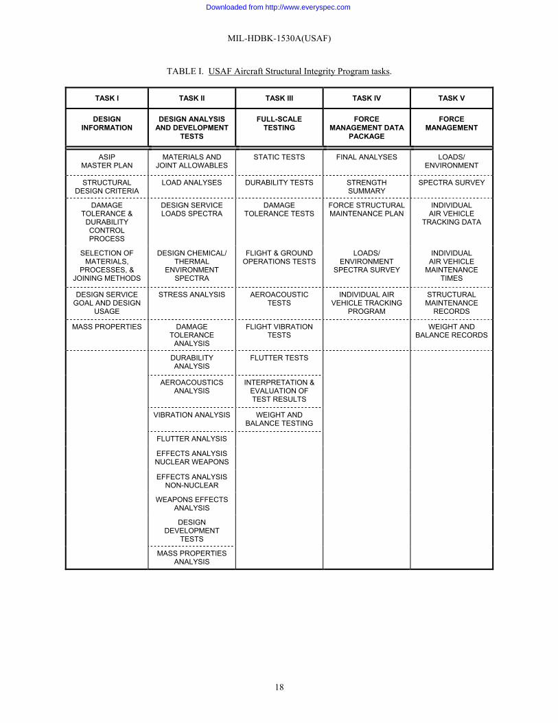
MIL-HDBK-1530A(USAF)
18
TABLE I. USAF Aircraft Structural Integrity Program tasks.
TASK I TASK II TASK III TASK IV TASK V
DESIGNINFORMATION
DESIGN ANALYSISAND DEVELOPMENT
TESTS
FULL-SCALETESTING
FORCEMANAGEMENT DATA
PACKAGE
FORCEMANAGEMENT
ASIPMASTER PLAN
MATERIALS ANDJOINT ALLOWABLES
STATIC TESTS FINAL ANALYSES LOADS/ENVIRONMENT
STRUCTURALDESIGN CRITERIA
LOAD ANALYSES DURABILITY TESTS STRENGTHSUMMARY
SPECTRA SURVEY
DAMAGETOLERANCE &
DURABILITYCONTROLPROCESS
DESIGN SERVICELOADS SPECTRA
DAMAGETOLERANCE TESTS
FORCE STRUCTURALMAINTENANCE PLAN
INDIVIDUALAIR VEHICLE
TRACKING DATA
SELECTION OFMATERIALS,
PROCESSES, &JOINING METHODS
DESIGN CHEMICAL/THERMAL
ENVIRONMENTSPECTRA
FLIGHT & GROUNDOPERATIONS TESTS
LOADS/ENVIRONMENT
SPECTRA SURVEY
INDIVIDUALAIR VEHICLE
MAINTENANCETIMES
DESIGN SERVICEGOAL AND DESIGN
USAGE
STRESS ANALYSIS AEROACOUSTICTESTS
INDIVIDUAL AIRVEHICLE TRACKING
PROGRAM
STRUCTURALMAINTENANCE
RECORDS
MASS PROPERTIES DAMAGETOLERANCE
ANALYSIS
FLIGHT VIBRATIONTESTS
WEIGHT ANDBALANCE RECORDS
DURABILITYANALYSIS
FLUTTER TESTS
AEROACOUSTICSANALYSIS
INTERPRETATION &EVALUATION OFTEST RESULTS
VIBRATION ANALYSIS WEIGHT ANDBALANCE TESTING
FLUTTER ANALYSIS
EFFECTS ANALYSISNUCLEAR WEAPONS
EFFECTS ANALYSISNON-NUCLEAR
WEAPONS EFFECTSANALYSIS
DESIGNDEVELOPMENT
TESTS
MASS PROPERTIESANALYSIS
Downloaded from http://www.everyspec.com
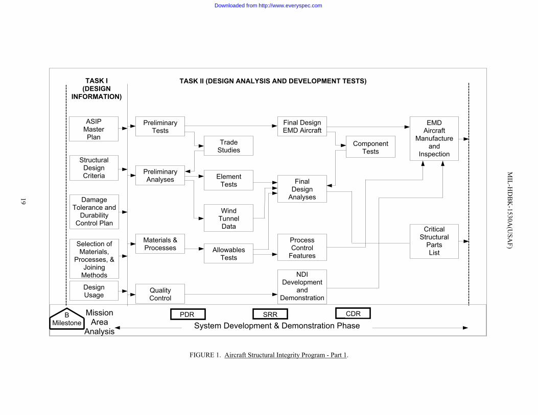
FIGURE 1. Aircraft Structural Integrity Program - Part 1.
SRR
TASK I(DESIGN
INFORMATION)
ASIPMasterPlan
StructuralDesignCriteria
DamageTolerance and
DurabilityControl Plan
Selection ofMaterials,
Processes, &Joining
Methods
DesignUsage
PreliminaryTests
PreliminaryAnalyses
Materials &Processes
QualityControl
TradeStudies
ElementTests
WindTunnelData
AllowablesTests
Final DesignEMD Aircraft
FinalDesign
Analyses
ProcessControl
Features
NDIDevelopment
andDemonstration
ComponentTests
EMDAircraft
Manufactureand
Inspection
CriticalStructural
PartsList
TASK II (DESIGN ANALYSIS AND DEVELOPMENT TESTS)
BMilestone System Development & Demonstration Phase
MissionArea
Analysis
PDR CDR
MIL-H
DB
K-1530A
(USA
F)
19
Downloaded from http://www.everyspec.com
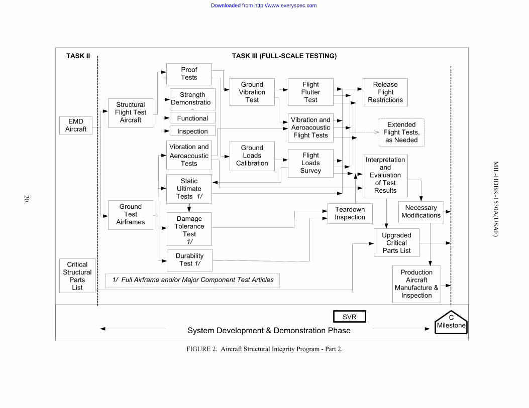
FIGURE 2. Aircraft Structural Integrity Program - Part 2.
EMDAircraft
CriticalStructural
PartsList
StructuralFlight Test
Aircraft
GroundTest
Airframes
ProofTests
StrengthDemonstratio
nFunctional
Inspection
StaticUltimateTests 1/
TASK III (FULL-SCALE TESTING)
DurabilityTest 1/
DamageTolerance
Test1/
TASK II
GroundVibration
Test
GroundLoads
Calibration
FlightFlutterTest
Vibration andAeroacousticFlight Tests
FlightLoadsSurvey
ReleaseFlight
Restrictions
ExtendedFlight Tests,as Needed
Interpretationand
Evaluationof TestResults
UpgradedCritical
Parts List
NecessaryModifications
ProductionAircraft
Manufacture &Inspection
TeardownInspection
SVR CMilestone
System Development & Demonstration Phase
Vibration andAeroacoustic
Tests
1/ Full Airframe and/or Major Component Test Articles
MIL-H
DB
K-1530A
(USA
F)
20
Downloaded from http://www.everyspec.com
FIGURE 3. Aircraft Structural Integrity Program - Part 3.
Interpretationand
Evaluationof
Test Results
AircraftModifications
andChanges
CriticalPartsList
AircraftManufacture,
Inspection
TASK III
ForceStructural
MaintenanceDocumentation(Design Usage)
IndividualAircraft
TrackingProgram
DataAcquisitionEquipment
DataAnalysisMethods Data
Analysis
Inspection and ModificationRequirements
When ? - Where ?How ? - Costs ?
Economic LifeEstimates
Design or BaselineOperational Usage
Updated ForceStructural
MaintenanceDocumentation
Baseline
Operational Usage
Developmentof BaselineOperational
Spectra
AdjustedInspection and
ModificationTimes for
Individual Aircraft
Verification Tests Damage Tolerance and Durability Control
TASK IV (FORCE MANAGEMENT DATA PACKAGE)
DataAcquisitionProcedures
PCACMilestone
Production Aircraft Manufacturing
Production and Deployment Phase
MIL-H
DB
K-1530A
(USA
F)
21
Aircraft Fleet Operations
Loads/Environment Spectra Survey
Downloaded from http://www.everyspec.com
FIGURE 4. Aircraft Structural Integrity Program - Part 4.
TASK V (FORCE MANAGEMENT)TASK IV
Aircraft Fleet Operations
StructuralMaintenance
Documentation
BaselineOperational
Spectra
Inspectionand
Modificationof
IndividualAircraft
UpdatedOperational
Spectra
UpdatedInspection andModification of
Individual Aircraft
UpdatedOperational
Spectra
UpdatedInspection andModification of
Individual Aircraft
Field ProblemSolution
(analysis, groundtest, flight test)
Field ProblemSolution
(analysis, groundtest, flight test)
FleetRetirementProduction and Deployment Phase
Individual Aircraft Data Tracking
Loads/Environment Spectra Survey
MIL-H
DB
K-1530A
(USA
F)
22
Production Aircraft Manufacturing
Downloaded from http://www.everyspec.com
MIL-HDBK-1530A(USAF)APPENDIX A
23
APPENDIX A
ADDITIONAL GUIDANCE FOR NEW, OFF-THE- SHELF AIR VEHICLES
A.1 Structural qualification. The following general guidance should be used to tailor the guidance contained inthe main body of this document to conform to a specific program. The degree of structural development necessaryshould be determined as part of an in-house technical assessment. It should be noted that even a FAR-25-certifiedair vehicle could be a major structural development if major mission variations adversely affected the structural life.
A.1.1 Performance requirements. The structural performance requirements should be established by theProgram Manager. The structural performance requirements will identify the structural criteria which should beused to establish the strength, durability, and damage-tolerance of the air vehicle. This should include weights,speeds, altitudes, and runway surface preparation from which the air vehicle is to be operated.
A.1.2 Service goal concept. The Program Manager should also establish the desired service goal concept forthe air vehicle, the missions to be flown, and the usage of those missions during the service goal.
A.1.3 Preliminary structural evaluation. The candidate air vehicle should be examined through apreliminary structural evaluation. This effort should characterize the structural integrity of the proposed system andshould be based on the database that currently exists for the air vehicle. This should be a critical evaluation of thecertification basis for the air vehicle as compared to the requirements of the ASIP. The design criteria used in thecertification process should be the basis for this evaluation. The ASIP should be tailored to be consistent with theintended use of the air vehicle and the scope of this evaluation. The primary effort should be an examination ofvibration, acoustic, flutter, loads, static strength, fatigue and damage tolerance analyses, and the associated testingdescribed in the first three tasks of the ASIP. The guidance for acceptable compliance with these tasks can be foundin JSSG-2006. Particular attention should be given to the third task of ASIP, which includes the full-scale testing.The elements of this task—which include the laboratory static and durability tests and the flight and groundoperations test—represent significant costs to the program if not previously executed or executed improperly. Thelack of adequate testing may also mean there could be high risk that there is a structural deficiency. The individualair vehicle tracking program and the loads/environment spectra survey found in fourth task of the ASIP will, ingeneral, not be included in the original certification basis for the air vehicle. For FAR Part 25 air vehicles, many ofthe ASIP required analyses and tests are routinely accomplished during the certification process However, theyshould be critically examined for compliance with the ASIP. For FAR Part 23 air vehicles, the requirement for theevaluation is normally greater, since the structural requirements for these air vehicles are less stringent than for theFAR Part 25 air vehicles. In addition, consideration should be given to rules that were current at the time thecertification took place, since the requirements have been significantly modified over the years.
The certification basis for air vehicles certified by foreign authorities should be examined on a case-by-casebasis. If the certification basis is not considered adequate, then the air vehicle should be subjected to an in-depthtechnical assessment. This technical assessment should be based on the data provided by the contractor. Thisassessment should, in general, include effort in the vibration, acoustic, flutter, load, stress, fatigue, and damagetolerance analysis disciplines. Durability and damage tolerance are typically the areas where the certification basisis lacking.
The available database should be used for the in-house durability and damage tolerance assessment to locatecritical areas of the structure. This should be a limited effort and should concentrate on a few generic areas andareas which, if found deficient, could result in major modification costs. The next task should be to generate aflight-by-flight spectra of stresses at these critical locations. These spectra should represent the lifetime operation ofthe air vehicle, which should include loads from taxi, maneuvering, turbulence, and landing impact. Fractureanalyses using these spectra of stresses should be used to estimate the durability and damage tolerance capability ofthe air vehicle. In some cases, the use of coupon testing may be required to provide validation of these analyses.These studies should be used as a basis to assess the economic impact of bringing the air vehicle into the U.S. AirForce inventory. If the certification basis is considered adequate, then the compliance with the U.S. Air Force
Downloaded from http://www.everyspec.com
MIL-HDBK-1530A(USAF)APPENDIX A
24
structural performance requirements for the candidate air vehicle is evaluated. This effort should examine thedifferences between the structural design criteria of the candidate air vehicle and the U.S. Air Force structuraldesign criteria. Each aspect of the criteria that affects the vibration, acoustic, flutter, load, strength, fatigue, anddamage tolerance capability of the air vehicle should be examined. For example, the candidate air vehicle may havebeen designed to a limit load factor of 3.5, while the U.S. Air Force operations dictate the need for a limit loadfactor of 4.5. This indicates a deficiency in strength and possibly in durability and damage tolerance capability. Anincompatibility in the velocity/altitude boundary requirements may indicate a deficiency in the flutter margins. Ifthe structural performance requirements for the air vehicle are not compatible with the design of the candidate airvehicle, then the air vehicle is subjected to a technical assessment. If it is compatible, then the candidate air vehicleis assessed against the service life goals, missions, and usage desired. If the candidate air vehicle is not compatiblewith the desired service goals, missions, and usage, then it goes to the technical assessment. If it is compatible, thenthe candidate air vehicle service history is examined. For this task, the maintenance program for the candidate airvehicle and its operational history would be assessed. Also, it should be determined if it has adequate past andcontinuing operational experience to ensure that any potential economic issue with the air vehicle has been revealedand that any potential safety issue will be revealed before it occurs on a USAF air vehicle. If there is adequateservice history, then the air vehicle should be expected to meet the structural requirements, and the evaluationwould be complete. If it is judged that there is not an adequate service history, then it should be subjected to atechnical assessment.
A.1.4 Additional analyses. If the air vehicle cannot meet the requirements from A.1.2, then suitable additionalanalyses should be performed in an in-house technical assessment to ensure that any potential economic or safetyproblem is revealed. In many cases, FAR Part 25 air vehicles have been subjected to a damage tolerance assessmentas part of the FAA requirements for a Supplementary Structural Inspection Document (SSID). In these cases, thisdamage tolerance assessment can be modified by the contractor to evaluate the impact of usage changes. The in-house assessment should be based on information from the contractor. Typically, this information is more easilyobtained during on-site visits to the contractor facility. This information should include information on designconfiguration and design usage, loads, stresses, tests, corrosion protection systems, and service experience.
A.1.5 Risk assessment. If the in-house assessment of the candidate air vehicle shows it can meet the desiredobjectives, then that information is given to the Program Manager. In the event the in-house assessment reveals thecandidate air vehicle has significant deficiencies or an inadequate database exists, then the results are submitted tothe Program Manager with an assessment of the associated risks so that a decision can be made to either reject thecandidate air vehicle or define further efforts.
A.1.6 New or modified structure. The engineering and manufacturing structural development andqualification guidance in this document are appropriate for new or extensively-modified structure. This describesthe level of effort, design analyses, and testing required regardless of who certifies the new or modified structure.An in-house structural assessment of the magnitude of the structural modification can be conducted to clarify furtherthe required level of design effort, analyses, and testing.
A.1.7 Airframe condition. Particularly difficult structural integrity problems often accompany theprocurement of aging, off-the-shelf aircraft. There are many used aircraft in the marketplace which may bepurchased far below the price of a new, off-the-shelf air vehicle. The reasons for the low price on these aircraft maybe that they have flown beyond their design service goal, they have corrosion problems, they have widespreadfatigue problems, they have numerous repairs (many of which are not damage tolerant), or any combination of thesereasons. That is, they generally possess all of the ingredients to be classified as aging aircraft. Unfortunately, manyof these problems can be hidden from view and the aircraft may appear to be airworthy. Experience has shown thatsignificant problems do exist and the cost of refurbishing these aircraft is considerably above original expectations.
Downloaded from http://www.everyspec.com
MIL-HDBK-1530A(USAF)APPENDIX B
25
APPENDIX B
ADDITIONAL GUIDANCE FOR AGING AIR VEHICLES
B.1 Aging air vehicles. For a new air vehicle, the development of the Force Structural Maintenance Plan (FSMP)in Task IV provides the basis for the maintenance costs expected to be incurred for the air vehicle during its designservice goal. When the FSMP needs to be changed because the air vehicle: 1.) has overflown its design servicegoal, 2.) is corroded, 3.) has reached the time of onset of widespread fatigue damage (WFD), or 4.) has beenrepaired; then the air vehicle is said to be aging.
B.1.1 Operations beyond the design service goal of the air vehicle. If the air vehicle has flown or isexpected to be flown beyond its design service lifetime, the service inspection program should be updated to includenecessary additional structural locations and/or inspection intervals to ensure structural integrity. This isaccomplished through a damage tolerance assessment to search for new structural areas which may need to beinspected or modified. This would include a review of inspection results from operational air vehicles and a reviewof findings from previous durability testing. If an air vehicle can be removed from operational service, then ateardown inspection should be performed to determine if there are any fatigue cracking or corrosion problems notpredicted earlier through design and test.
B.1.2 Corrosion. Inspections of individual air vehicles should be accomplished to ascertain the condition ofthe airframes with respect to corrosion. Emphasis should be placed on corrosion detection through nondestructiveinspections and prevention. For those areas found to be corroded, the preferred approach is to eliminate thecorrosion by removing it or replacing the structural elements in question. This may not be feasible in rare casesbecause of near-term operational requirements. In these cases, an assessment should be accomplished to determinethe change in the inspection program that will account for the influence of corrosion on structural integrity.
B.1.3 Widespread fatigue damage. An initial prediction of the time of onset of WFD should be made basedon the results from the durability test, air vehicle inspections, and usage tracking. Before the predicted time of theonset of WFD, a teardown inspection of a high-time air vehicle needs to be accomplished to validate the crackdistribution function. This refined distribution should be used to recalculate the time of onset of WFD. Beforeoperational air vehicles reach this time, a detailed nondestructive inspection program is needed to validate theprediction. When the air vehicle has reached the time of onset of WFD, then it should be modified to remove theproblem since routine inspections are inadequate to protect flight safety.
B.1.4 Repairs. Both metallic and composite repairs should be designed to be damage-tolerant in addition tosatisfying the strength and aeroelastic requirements. Further, they should be added to the FSMP so that they can beproperly tracked to determine the inspection times. Additionally, a database needs to be established to maintainconfiguration control of air vehicle repairs. Any interaction of repairs should be taken into consideration in thedamage tolerance assessment of them.
Downloaded from http://www.everyspec.com
MIL-HDBK-1530A(USAF)
26
Custodian: Preparing activity:Air Force – 11 Air Force – 11
(Project 15GP-F007)
Downloaded from http://www.everyspec.com
STANDARDIZATION DOCUMENT IMPROVEMENT PROPOSALINSTRUCTIONS
1. The preparing activity must complete blocks 1, 2, 3, and 8. In block 1, both the document number and revision letter should be given.
2. The submitter of this form must complete blocks 4, 5, 6, and 7, and send to preparing activity.
3. The preparing activity must provide a reply within 30 days from receipt of the form.
NOTE: This form may not be used to request copies of documents, nor to request waivers, or clarification of requirements on current contracts.Comments submitted on this form do not constitute or imply authorization to waive any portion of the referenced document(s) or to amend contractualrequirements.
I RECOMMEND A CHANGE: 1. DOCUMENT NUMBERMIL-HDBK-1530A(USAF)
2. DOCUMENT DATE (YYYYMMDD)20020124
3. DOCUMENT TITLE
AIRCRAFT STRUCTURAL INTEGRITY PROGRAM, GENERAL GUIDELINES FOR4. NATURE OF CHANGE (Identify paragraph number and include proposed rewrite, if possible. Attach extra sheets, as needed.)
5. REASON FOR RECOMMENDATION
6. SUBMITTERa. NAME (Last, First, Middle Initial) b. ORGANIZATION
c. ADDRESS (Include Zip Code) d. TELEPHONE (Include Area Code)(1) Commercial
(2) DSN(if applicable)
7.DATE SUBMITTED(YYYYMMDD)
8. PREPARING ACTIVITY
a. NAME
AIR FORCE CODE 11b. TELEPHONE Include Area Code)(1) Commercial (2) DSN
(937) 255-6282 785-6282c. ADDRESS (Include Zip Code)
ASC/ENOI2530 LOOP ROAD WESTWRIGHT-PATTERSON AFB OH 45433-7101
IF YOU DO NOT RECEIVE A REPLY WITHIN 45 DAYS, CONTACT:
Defense Standardization Program Office (DLSC-LM)8725 John J. Kingman Road, Suite 2533; Ft. Belvoir, VA 22060-2533Telephone (703) 767-6888 DSN 427-6888
DD Form 1426, FEB 1999 (EG) PREVIOUS EDITION IS OBSOLETE. WHS/DIOR, Feb 99
Downloaded from http://www.everyspec.com