Embed Size (px)
Citation preview
R e f r i g e r a t e d A i r D r y e r s
M a g n u m S e r i e s
PREMIUM PRODUCTS FOR INDUSTRY
AIRTEKPREMIUM PRODUCTS FOR INDUSTRY
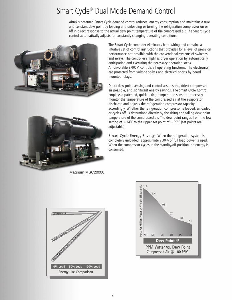
Airtek’s patented Smart Cycle demand control reduces energy consumption and maintains a trueand constant dew point by loading and unloading or turning the refrigeration compressor on oroff in direct response to the actual dew point temperature of the compressed air. The Smart Cyclecontrol automatically adjusts for constantly changing operating conditions.
The Smart Cycle computer eliminates hard wiring and contains aintuitive set of control instructions that provides for a level of precisionperformance not possible with the conventional systems of switchesand relays. The controller simplifies dryer operation by automaticallyanticipating and executing the necessary operating steps.A nonvolatile EPROM controls all operating functions. The electronicsare protected from voltage spikes and electrical shorts by boardmounted relays.
Direct dew point sensing and control assures the, driest compressedair possible, and significant energy savings. The Smart Cycle Controlemploys a patented, quick acting temperature sensor to preciselymonitor the temperature of the compressed air at the evaporatordischarge and adjusts the refrigeration compressor capacityaccordingly. Whether the refrigeration compressor is loaded, unloaded,or cycles off, is determined directly by the rising and falling dew pointtemperature of the compressed air. The dew point ranges from the lowsetting of +34OF to the upper set point of +39OF (set points areadjustable).
Smart Cycle Energy Savings: When the refrigeration system iscompletely unloaded, approximately 30% of full load power is used.When the compressor cycles in the standby/off position, no energy isconsumed.
Smart Cycle® Dual Mode Demand Control
2
Smart Cycle
Non-Cycling (Lo
ad/Unload Mode)
Conventional
Smar
t Cyc
le C
yclin
g (T
herm
al Ba
nk M
ode)
0% Load 50% Load 100% Load
Energy Use Comparison
Dew Point OF
PPM Water vs. Dew PointCompressed Air @ 100 PSIG
Parts
Per
Mill
ion
Wat
er b
y W
eigh
t (Th
ousa
nds)
70 60 50 40 35 32
1.9
.51.57
.67
.98
1.4
Magnum MSC20000
Airtek Magnum dryers DO NOT use a hot gas bypass valve. Compressor cylinder unloaders together with Smart Cycleunloading obtain optimum performance and energy savings. In simple terms, a hot gas bypass valve places a false loadon the refrigeration system, whereas the Smart Cycle system design does not. It uses only the energy necessary toachieve desired dew point.
Conventional dryers control the evaporator’s refrigerant pressure temperature using a hot gas valve designed with theassumption that if the refrigerant is 33OF the air will come out at 39OF. The truth is hot gas valves swing 10-15 psi/8-12OFbetween fully open/closed allowing the refrigerant in the evaporator to rise to 40-45OF before it actually stops addingfalse load to the refrigeration system. This translates to higher dew points and wasted energy.
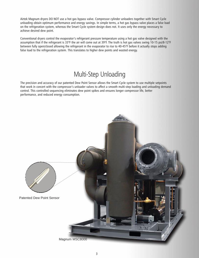
The precision and accuracy of our patented Dew Point Sensor allows the Smart Cycle system to use multiple setpointsthat work in concert with the compressor’s unloader valves to affect a smooth multi-step loading and unloading demandcontrol. This controlled sequencing eliminates dew point spikes and ensures longer compressor life, betterperformance, and reduced energy consumption.
3
Multi-Step Unloading
Patented Dew Point Sensor
Magnum MSC8000
Dual Mode
4
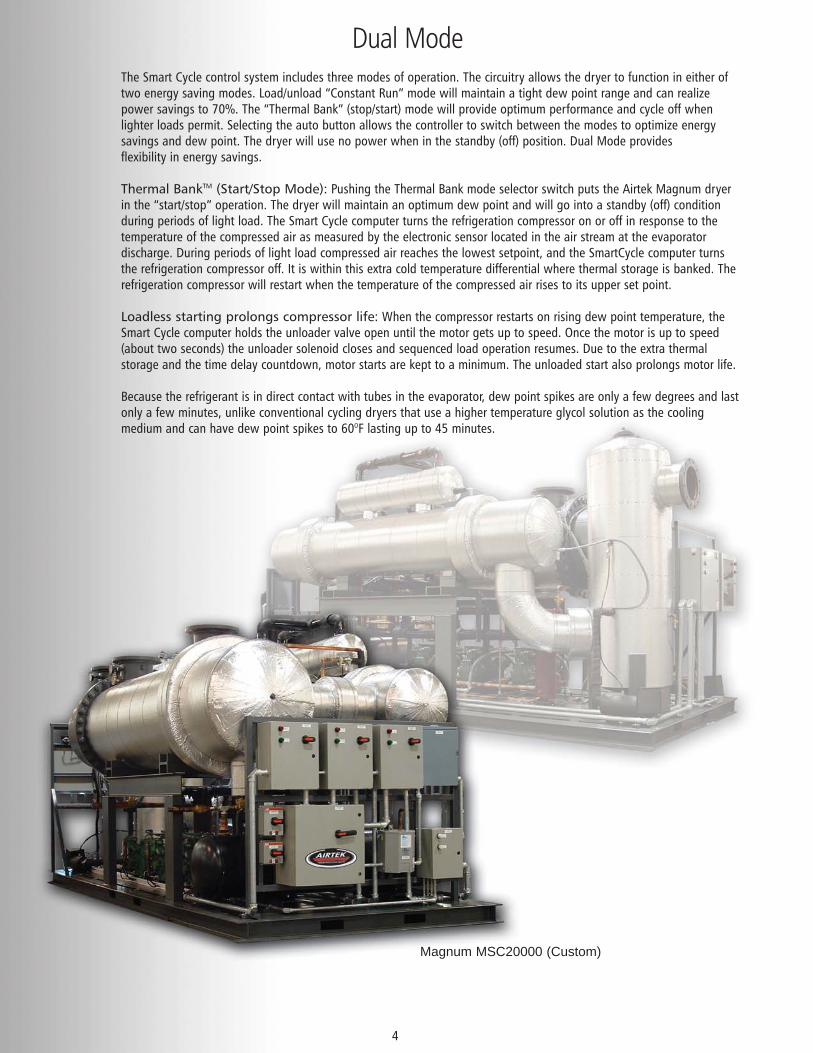
The Smart Cycle control system includes three modes of operation. The circuitry allows the dryer to function in either oftwo energy saving modes. Load/unload “Constant Run” mode will maintain a tight dew point range and can realizepower savings to 70%. The “Thermal Bank” (stop/start) mode will provide optimum performance and cycle off whenlighter loads permit. Selecting the auto button allows the controller to switch between the modes to optimize energysavings and dew point. The dryer will use no power when in the standby (off) position. Dual Mode providesflexibility in energy savings.
Thermal BankTM (Start/Stop Mode): Pushing the Thermal Bank mode selector switch puts the Airtek Magnum dryerin the “start/stop” operation. The dryer will maintain an optimum dew point and will go into a standby (off) conditionduring periods of light load. The Smart Cycle computer turns the refrigeration compressor on or off in response to thetemperature of the compressed air as measured by the electronic sensor located in the air stream at the evaporatordischarge. During periods of light load compressed air reaches the lowest setpoint, and the SmartCycle computer turnsthe refrigeration compressor off. It is within this extra cold temperature differential where thermal storage is banked. Therefrigeration compressor will restart when the temperature of the compressed air rises to its upper set point.
Loadless starting prolongs compressor life: When the compressor restarts on rising dew point temperature, theSmart Cycle computer holds the unloader valve open until the motor gets up to speed. Once the motor is up to speed(about two seconds) the unloader solenoid closes and sequenced load operation resumes. Due to the extra thermalstorage and the time delay countdown, motor starts are kept to a minimum. The unloaded start also prolongs motor life.
Because the refrigerant is in direct contact with tubes in the evaporator, dew point spikes are only a few degrees and lastonly a few minutes, unlike conventional cycling dryers that use a higher temperature glycol solution as the coolingmedium and can have dew point spikes to 60OF lasting up to 45 minutes.
Magnum MSC20000 (Custom)
Performance Charts
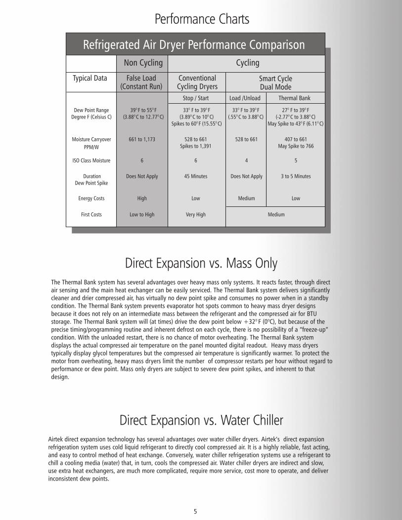
Direct Expansion vs. Water Chiller
5
Airtek direct expansion technology has several advantages over water chiller dryers. Airtek’s direct expansionrefrigeration system uses cold liquid refrigerant to directly cool compressed air. It is a highly reliable, fast acting,and easy to control method of heat exchange. Conversely, water chiller refrigeration systems use a refrigerant tochill a cooling media (water) that, in turn, cools the compressed air. Water chiller dryers are indirect and slow,use extra heat exchangers, are much more complicated, require more service, cost more to operate, and deliverinconsistent dew points.
Refrigerated Air Dryer Performance Comparison
False Load(Constant Run)
ConventionalCycling Dryers
Stop / Start Load /Unload Thermal Bank
Smart CycleDual Mode
Typical Data
Dew Point RangeDegree F (Celsius C)
Moisture Carryover
PPM/W
661 to 1,173 528 to 661 Spikes to 1,391
528 to 661 407 to 661May Spike to 766
DurationDew Point Spike
Does Not Apply 45 Minutes Does Not Apply 3 to 5 Minutes
Energy Costs High Low Medium Low
First Costs Low to High Very High Medium
ISO Class Moisture 6 6 4 5
39O F to 55O F(3.88O C to 12.77O C)
33O F to 39O F(3.89O C to 10O C)
Spikes to 60O F (15.55O C)
27O F to 39O F(-2.77O C to 3.88O C)
May Spike to 43O F (6.11O C)
33O F to 39O F(.55O C to 3.88O C)
CyclingNon Cycling
Direct Expansion vs. Mass OnlyThe Thermal Bank system has several advantages over heavy mass only systems. It reacts faster, through directair sensing and the main heat exchanger can be easily serviced. The Thermal Bank system delivers significantlycleaner and drier compressed air, has virtually no dew point spike and consumes no power when in a standbycondition. The Thermal Bank system prevents evaporator hot spots common to heavy mass dryer designsbecause it does not rely on an intermediate mass between the refrigerant and the compressed air for BTUstorage. The Thermal Bank system will (at times) drive the dew point below +32O F (0OC), but because of theprecise timing/programming routine and inherent defrost on each cycle, there is no possibility of a “freeze-up”condition. With the unloaded restart, there is no chance of motor overheating. The Thermal Bank systemdisplays the actual compressed air temperature on the panel mounted digital readout. Heavy mass dryerstypically display glycol temperatures but the compressed air temperature is significantly warmer. To protect themotor from overheating, heavy mass dryers limit the number of compressor restarts per hour without regard toperformance or dew point. Mass only dryers are subject to severe dew point spikes, and inherent to thatdesign.
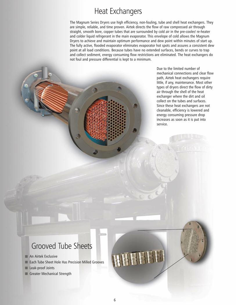
The Magnum Series Dryers use high efficiency, non-fouling, tube and shell heat exchangers. Theyare simple, reliable, and time proven. Airtek directs the flow of raw compressed air throughstraight, smooth bore, copper tubes that are surrounded by cold air in the pre-cooler/ re-heaterand colder liquid refrigerant in the main evaporator. This envelope of cold allows the MagnumDryers to achieve and maintain optimum performance and dew point within minutes of start up.The fully active, flooded evaporator eliminates evaporator hot spots and assures a consistent dewpoint at all load conditions. Because tubes have no extended surfaces, bends or curves to trapand collect sediment, energy consuming flow restrictions are eliminated. The heat exchangers donot foul and pressure differential is kept to a minimum.
Due to the limited number ofmechanical connections and clear flowpath, Airtek heat exchangers requirelittle, if any, maintenance. Most othertypes of dryers direct the flow of dirtyair through the shell of the heatexchanger where the dirt and oilcollect on the tubes and surfaces.Since these heat exchangers are notcleanable, efficiency is lowered andenergy consuming pressure dropincreases as soon as it is put intoservice.
Heat Exchangers
6
Grooved Tube SheetsAn Airtek ExclusiveEach Tube Sheet Hole Has Precision Milled GroovesLeak-proof JointsGreater Mechanical Strength
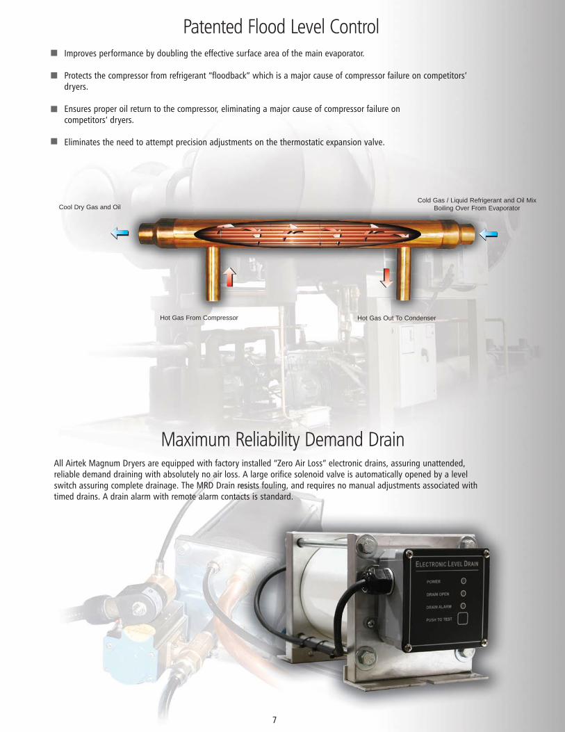
Patented Flood Level Control
All Airtek Magnum Dryers are equipped with factory installed “Zero Air Loss” electronic drains, assuring unattended,reliable demand draining with absolutely no air loss. A large orifice solenoid valve is automatically opened by a levelswitch assuring complete drainage. The MRD Drain resists fouling, and requires no manual adjustments associated withtimed drains. A drain alarm with remote alarm contacts is standard.
Maximum Reliability Demand Drain
7
Improves performance by doubling the effective surface area of the main evaporator.
Protects the compressor from refrigerant “floodback” which is a major cause of compressor failure on competitors’dryers.
Ensures proper oil return to the compressor, eliminating a major cause of compressor failure oncompetitors’ dryers.
Eliminates the need to attempt precision adjustments on the thermostatic expansion valve.
Cool Dry Gas and OilCold Gas / Liquid Refrigerant and Oil Mix
Boiling Over From Evaporator
Hot Gas From Compressor Hot Gas Out To Condenser
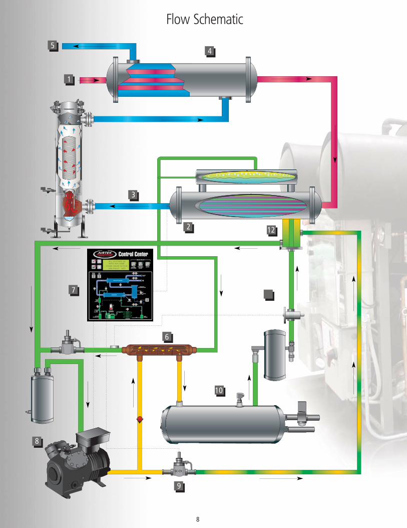
Flow Schematic
8
SC-CVSC-CV
9
7
3
4
1
5
122
11
10
6
8
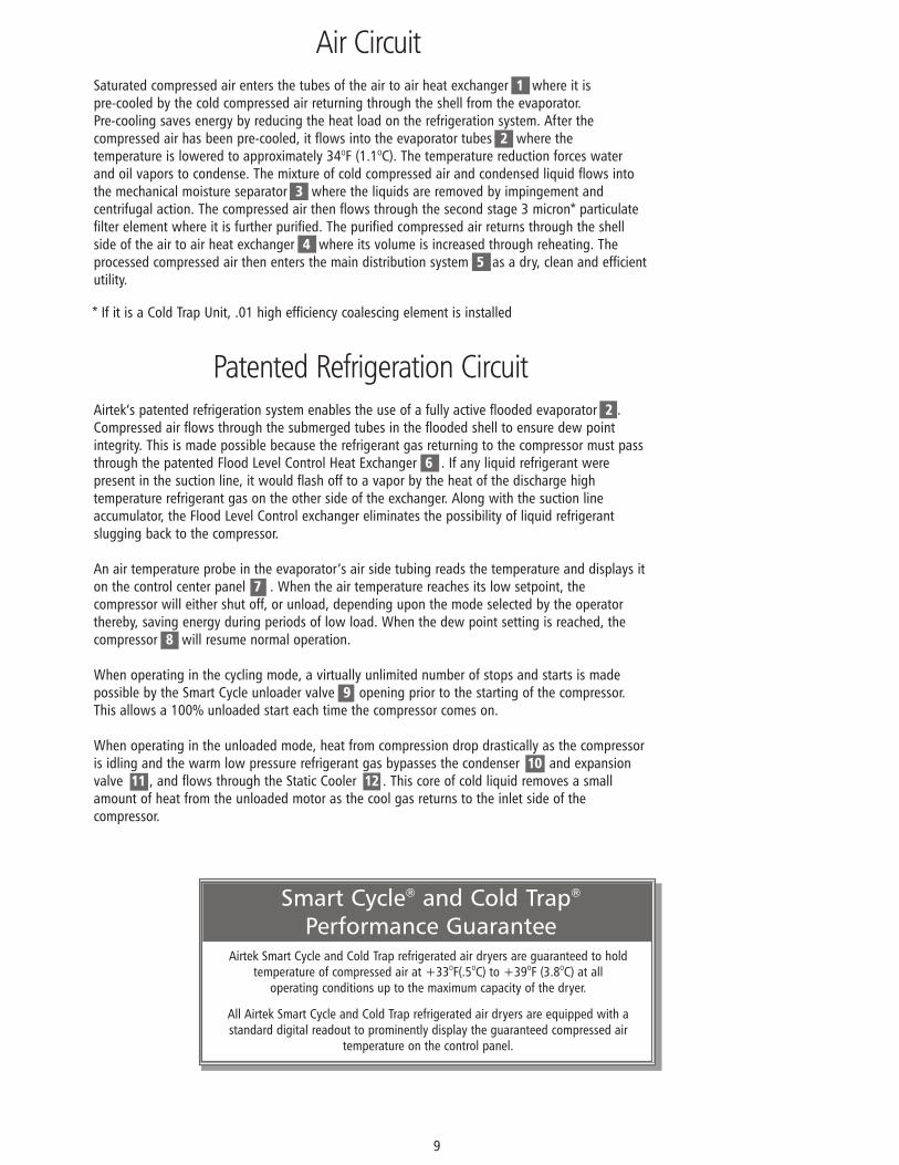
Airtek’s patented refrigeration system enables the use of a fully active flooded evaporator 2 .Compressed air flows through the submerged tubes in the flooded shell to ensure dew pointintegrity. This is made possible because the refrigerant gas returning to the compressor must passthrough the patented Flood Level Control Heat Exchanger 6 . If any liquid refrigerant werepresent in the suction line, it would flash off to a vapor by the heat of the discharge hightemperature refrigerant gas on the other side of the exchanger. Along with the suction lineaccumulator, the Flood Level Control exchanger eliminates the possibility of liquid refrigerantslugging back to the compressor.
An air temperature probe in the evaporator’s air side tubing reads the temperature and displays iton the control center panel 7 . When the air temperature reaches its low setpoint, thecompressor will either shut off, or unload, depending upon the mode selected by the operatorthereby, saving energy during periods of low load. When the dew point setting is reached, thecompressor 8 will resume normal operation.
When operating in the cycling mode, a virtually unlimited number of stops and starts is madepossible by the Smart Cycle unloader valve 9 opening prior to the starting of the compressor.This allows a 100% unloaded start each time the compressor comes on.
When operating in the unloaded mode, heat from compression drop drastically as the compressoris idling and the warm low pressure refrigerant gas bypasses the condenser 10 and expansionvalve 11 , and flows through the Static Cooler 12 . This core of cold liquid removes a smallamount of heat from the unloaded motor as the cool gas returns to the inlet side of thecompressor.
Air Circuit
Patented Refrigeration Circuit
9
Smart Cycle® and Cold Trap®
Performance GuaranteeAirtek Smart Cycle and Cold Trap refrigerated air dryers are guaranteed to hold
temperature of compressed air at +33OF(.5OC) to +39OF (3.8OC) at all operating conditions up to the maximum capacity of the dryer.
All Airtek Smart Cycle and Cold Trap refrigerated air dryers are equipped with astandard digital readout to prominently display the guaranteed compressed air
temperature on the control panel.
Saturated compressed air enters the tubes of the air to air heat exchanger 1 where it ispre-cooled by the cold compressed air returning through the shell from the evaporator.Pre-cooling saves energy by reducing the heat load on the refrigeration system. After thecompressed air has been pre-cooled, it flows into the evaporator tubes 2 where thetemperature is lowered to approximately 34OF (1.1OC). The temperature reduction forces waterand oil vapors to condense. The mixture of cold compressed air and condensed liquid flows intothe mechanical moisture separator 3 where the liquids are removed by impingement andcentrifugal action. The compressed air then flows through the second stage 3 micron* particulatefilter element where it is further purified. The purified compressed air returns through the shellside of the air to air heat exchanger 4 where its volume is increased through reheating. Theprocessed compressed air then enters the main distribution system 5 as a dry, clean and efficientutility.
* If it is a Cold Trap Unit, .01 high efficiency coalescing element is installed
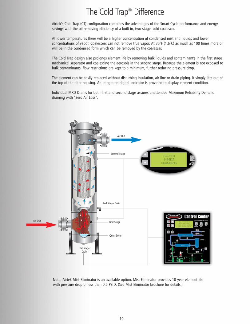
Airtek’s Cold Trap (CT) configuration combines the advantages of the Smart Cycle performance and energysavings with the oil removing efficiency of a built in, two stage, cold coalescer.
At lower temperatures there will be a higher concentration of condensed mist and liquids and lowerconcentrations of vapor. Coalescers can not remove true vapor. At 35OF (1.6OC) as much as 100 times more oilwill be in the condensed form which can be removed by the coalescer.
The Cold Trap design also prolongs element life by removing bulk liquids and contaminant's in the first stagemechanical separator and coalescing the aerosols in the second stage. Because the element is not exposed tobulk contaminants, flow restrictions are kept to a minimum, further reducing pressure drop.
The element can be easily replaced without disturbing insulation, air line or drain piping. It simply lifts out ofthe top of the filter housing. An integrated digital indicator is provided to display element condition.
Individual MRD Drains for both first and second stage assures unattended Maximum Reliability Demanddraining with “Zero Air Loss”.
The Cold Trap® Difference
10
Second Stage
Air Out
1st StageDrain
Quiet Zone
First StageAir Out
2nd Stage Drain
Note: Airtek Mist Eliminator is an available option. Mist Eliminator provides 10-year element lifewith pressure drop of less than 0.5 PSID. (See Mist Eliminator brochure for details.)
Control Center
11
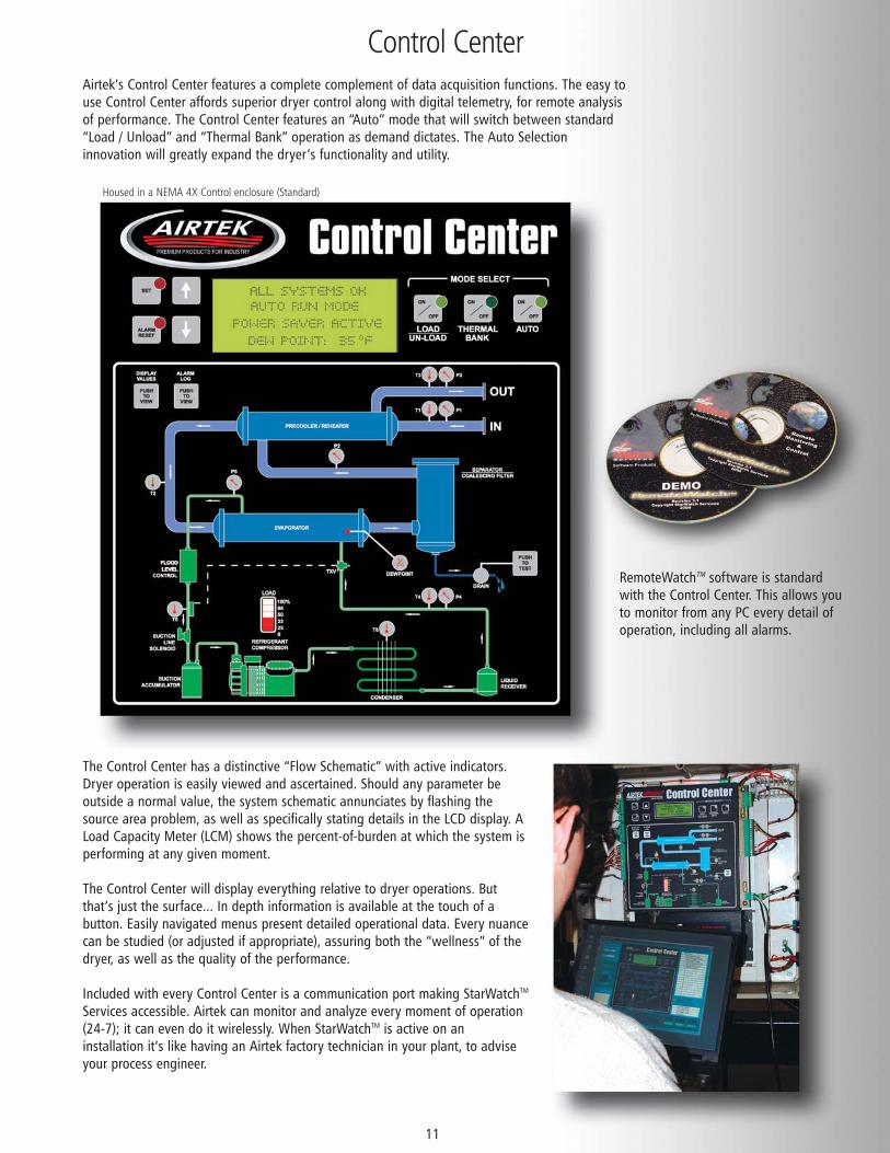
Airtek’s Control Center features a complete complement of data acquisition functions. The easy touse Control Center affords superior dryer control along with digital telemetry, for remote analysisof performance. The Control Center features an “Auto” mode that will switch between standard“Load / Unload” and “Thermal Bank” operation as demand dictates. The Auto Selectioninnovation will greatly expand the dryer’s functionality and utility.
The Control Center has a distinctive “Flow Schematic” with active indicators.Dryer operation is easily viewed and ascertained. Should any parameter beoutside a normal value, the system schematic annunciates by flashing thesource area problem, as well as specifically stating details in the LCD display. ALoad Capacity Meter (LCM) shows the percent-of-burden at which the system isperforming at any given moment.
The Control Center will display everything relative to dryer operations. Butthat’s just the surface... In depth information is available at the touch of abutton. Easily navigated menus present detailed operational data. Every nuancecan be studied (or adjusted if appropriate), assuring both the “wellness” of thedryer, as well as the quality of the performance.
Included with every Control Center is a communication port making StarWatchTM
Services accessible. Airtek can monitor and analyze every moment of operation(24-7); it can even do it wirelessly. When StarWatchTM is active on aninstallation it’s like having an Airtek factory technician in your plant, to adviseyour process engineer.
RemoteWatchTM software is standardwith the Control Center. This allows youto monitor from any PC every detail ofoperation, including all alarms.
Housed in a NEMA 4X Control enclosure (Standard)
Airtek Designs With The Following Priorities
12
ReliabilityReliability is achieved using our proven design and components, along with quality workmanship. Examples of this principle areobvious when looking at our rugged steel bases and frames, as well as our heat exchangers that resist fouling and minimize anypossibility of a leak.
In addition, the patented Flood Level Control exchanger eliminates problems associated with compressor floodback and poor oilreturn that are commonly experienced with other dryers. The “Loadless Starting” feature reduces the start up load on therefrigeration compressor by 80%. Low refrigerant warning and shutdown prevents compressor failure in the refrigeration system.Additional safety devices include a “low pressure side pump down”, suction accumulator, high pressure shutdown switch withmanual reset, and both liquid and suction line filter / dryers to assure clean refrigeration circuits.
OperationAirtek dryers are designed so that minimal operator attention is needed. Operation is as simple as turning the dryer on.The on-board computer then controls the unit so that it will react to ever-changing operating conditions.
A diagnostic control system will inform the operator of the dew point, as well as warn of any upset conditions that mayaffect dryer performance.
Drain valves activate only when necessary and prevent valuable compressed air from being vented. A drain alarm warnsof any malfunction.
MaintenanceAirtek dryers are designed to require as little routine maintenance as possible. Examples of this design principle can beseen in our choice of smooth bore non-fouling heat exchangers, along with electronic rather than mechanical controldevices. Other examples: use of bolts with captive nuts instead of sheet metal screws; large open spaces for easy accessto components; use of modular type electronic panel for ease of replacement; isolation valves on all refrigerant switchesallows service to any part of the system without having to reclaim the entire charge thereby, saving money anddrastically reducing down time.
Typical component selection and layout is simplistic, and use standard “off the shelf” items that can be supplied either byAirtek or your local refrigeration service company.
Air QualityThe customer purchases an air dryer to improve air quality. It is an essential component in their operation. Poor airquality results in problems with product quality and production processes.
The heart of Airtek’s air quality design is the unique, patented Smart Cycle system, which directly senses the airtemperature leaving the evaporator, and controls the refrigeration compressor in response. It is the compressed airtemperature that controls the dryer functions. The system keeps the compressed air temperature in the 33-39OF(.55-3.8OC) range, shutting off or unloading the refrigeration compressor when the optimum dew point is achieved.The air temperature is displayed continuously by an LED readout on the control panel.
Energy SavingsEnergy savings is an additional bonus. With our proven design, the savings are built into each unit, which runs onlywhen inlet temperature demand and compressed air temperatures dictate.
Loadless starting, cycling the compressor on and off, or alternating between load and unloaded, and low overall systempressure drop allow for energy savings without sacrificing performance.
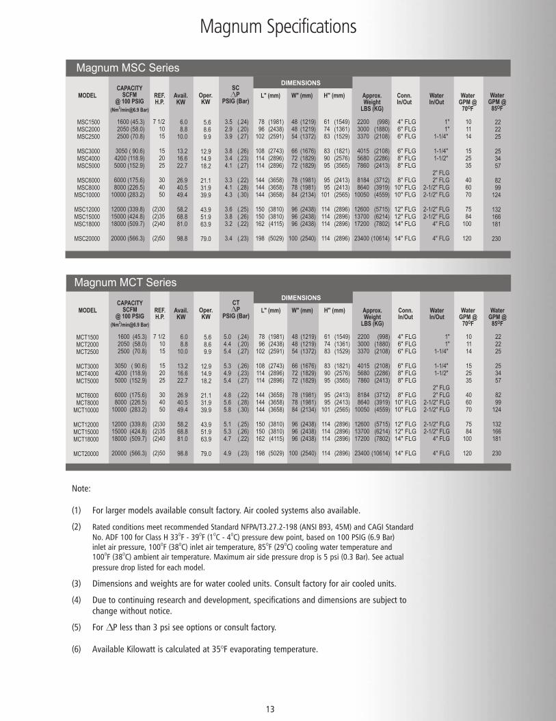
Magnum Specifications
13
MODELCAPACITY
SCFM@ 100 PSIG
(Nm3/[email protected] Bar)
REF.H.P.
L" (mm) W" (mm) Approx.Weight
LBS (KG)
Conn.In/Out
Avail.KW
Oper.KW
SC P
PSIG (Bar)
1600 (45.3) 2050 (58.0) 2500 (70.8)
3050 ( 90.6) 4200 (118.9) 5000 (152.9)
6000 (175.6) 8000 (226.5)
10000 (283.2)
12000 (339.8) 15000 (424.8) 18000 (509.7)
20000 (566.3)
3.5 2.9 3.9
3.8 3.4 4.1
3.3 4.1 4.3
3.6 3.8 3.2
3.4
(.24) (.20) (.27)
(.26) (.23) (.27)
(.22) (.28) (.30)
(.25) (.26) (.22)
(.23)
(1981) (2438) (2591)
(2743) (2896) (2896)
(3658) (3658) (3658)
(3810) (3810) (4115)
(5029)
(1219) (1219) (1372)
(1676) (1829) (1829)
(1981) (1981) (2134)
(2438) (2438) (2438)
(2540)
(1549) (1361) (1529)
(1821) (2576) (3565)
(2413) (2413) (2565)
(2896) (2896) (2896)
(2896)
(998) (1880) (2108)
(2108) (2286) (2413)
(3712) (3919) (4559)
(5715) (6214) (7802)
(10614)
4" FLG6" FLG 6" FLG
6" FLG 8" FLG 8" FLG
8" FLG 10" FLG 10" FLG
12" FLG12" FLG14" FLG
14" FLG
WaterIn/Out
1"1"
1-1/4"
1-1/4" 1-1/2"
2" FLG2" FLG
2-1/2" FLG2-1/2" FLG
2-1/2" FLG2-1/2" FLG
4" FLG
4" FLG
WaterGPM @
70OF
10 11 14
15 25 35
40 60 70
75 84
100
120
78 96
102
108 114 114
144 144 144
150 150 162
198
48 48 54
66 72 72
78 78 84
96 96 96
100
61 74 83
83 90 95
95 95
101
114 114 114
114
2200 3000 3370
4015 5680 7860
8184 8640
10050
12600 13700 17200
23400
H" (mm)
DIMENSIONS
MSC1500MSC2000MSC2500
MSC3000MSC4000MSC5000
MSC6000MSC8000
MSC10000
MSC12000MSC15000MSC18000
MSC20000
7 1/210 15
15 20 25
30 40 50
(2)30 (2)35 (2)40
(2)50
5.6 8.6 9.9
12.9 14.918.2
21.1 31.9 39.9
43.9 51.9 63.9
79.0
6.08.8
10.0
13.216.622.7
26.940.549.4
58.268.881.0
98.8
Magnum MSC Series
WaterGPM @
85OF
22 2225
25 34 57
82 99
124
132 166 181
230
MODELCAPACITY
SCFM@ 100 PSIG
(Nm3/[email protected] Bar)
REF.H.P.
L" (mm) W" (mm) Approx.Weight
LBS (KG)
Conn.In/Out
Avail.KW
Oper.KW
CT P
PSIG (Bar)
1600 (45.3) 2050 (58.0) 2500 (70.8)
3050 ( 90.6) 4200 (118.9) 5000 (152.9)
6000 (175.6) 8000 (226.5)
10000 (283.2)
12000 (339.8) 15000 (424.8) 18000 (509.7)
20000 (566.3)
(.24) (.20) (.27)
(.26) (.23) (.27)
(.22) (.28) (.30)
(.25) (.26) (.22)
(.23)
(1981) (2438) (2591)
(2743) (2896) (2896)
(3658) (3658) (3658)
(3810) (3810) (4115)
(5029)
(1219) (1219) (1372)
(1676) (1829) (1829)
(1981) (1981) (2134)
(2438) (2438) (2438)
(2540)
(1549) (1361) (1529)
(1821) (2576) (3565)
(2413) (2413) (2565)
(2896) (2896) (2896)
(2896)
(998) (1880) (2108)
(2108) (2286) (2413)
(3712) (3919) (4559)
(5715) (6214) (7802)
(10614)
4" FLG6" FLG 6" FLG
6" FLG 8" FLG 8" FLG
8" FLG 10" FLG 10" FLG
12" FLG12" FLG14" FLG
14" FLG
WaterIn/Out
1"1"
1-1/4"
1-1/4" 1-1/2"
2" FLG2" FLG
2-1/2" FLG2-1/2" FLG
2-1/2" FLG2-1/2" FLG
4" FLG
4" FLG
WaterGPM @
70OF
10 11 14
15 25 35
40 60 70
75 84
100
120
WaterGPM @
85OF
22 2225
25 34 57
82 99
124
132 166 181
230
78 96
102
108 114 114
144 144 144
150 150 162
198
48 48 54
66 72 72
78 78 84
96 96 96
100
61 74 83
83 90 95
95 95
101
114 114 114
114
2200 3000 3370
4015 5680 7860
8184 8640
10050
12600 13700 17200
23400
H" (mm)
DIMENSIONS
7 1/210 15
15 20 25
30 40 50
(2)30 (2)35 (2)40
(2)50
5.6 8.6 9.9
12.9 14.9 18.2
21.1 31.9 39.9
43.9 51.9 63.9
79.0
6.08.8
10.0
13.216.622.7
26.940.549.4
58.268.881.0
98.8
MCT1500MCT2000MCT2500
MCT3000MCT4000MCT5000
MCT6000MCT8000
MCT10000
MCT12000MCT15000MCT18000
MCT20000
5.0 4.4 5.4
5.3 4.9 5.4
4.8 5.6 5.8
5.1 5.3 4.7
4.9
Magnum MCT Series
Note:
(1) For larger models available consult factory. Air cooled systems also available.
(2) Rated conditions meet recommended Standard NFPA/T3.27.2-198 (ANSI B93, 45M) and CAGI StandardNo. ADF 100 for Class H 33OF - 39OF (1OC - 4OC) pressure dew point, based on 100 PSIG (6.9 Bar) inlet air pressure, 100OF (38OC) inlet air temperature, 85OF (29OC) cooling water temperature and 100OF (38OC) ambient air temperature. Maximum air side pressure drop is 5 psi (0.3 Bar). See actual pressure drop listed for each model.
(3) Dimensions and weights are for water cooled units. Consult factory for air cooled units.
(4) Due to continuing research and development, specifications and dimensions are subject to change without notice.
(5) For P less than 3 psi see options or consult factory.
(6) Available Kilowatt is calculated at 35OF evaporating temperature.
Standard Equipment
14
Smart Cycle® Loadless StartingSmart Cycle® Unloader ControlCompressor Vibration EliminatorsCompressor Crankcase HeaterCompressor, Semi-Hermetic Compressor Isolation SpringsCompressor Cylinder UnloadersFlood Level Control (patented)High Head Pressure SwitchLow Suction Pressure SwitchThermostatic Expansion ValveIsolation Valves ThroughoutWater Cooled CondenserAutomatic Water Control ValveOptional Air Cooled CondenserLow Ambient Fan Controls (Air Cooled Only)Replaceable Core Type Liquid Line Filter-DryerLiquid Line Sight GlassLiquid ReceiverSuction Line AccumulatorReplaceable Core Type Suction Line Filter-DryerSuction Line SolenoidCondenser Pressure Relief ValveAutomatic Pump Down CycleStarter (Across the Line)DisconnectSeparate High Voltage Enclosure
Refrigeration Group NEMA 4 Panel EncloserInstrumentation GroupDigital Readout
Modem FaultAir Pressure OutAir Temperature InAir Temperature OutRefrigerant Suction PressureRefrigerant Discharge PressureRefrigerant Liquid TemperatureRefrigerant Suction TemperatureSuper Heat TemperatureIntermediate Air TemperatureDew Point TemperatureWater/Ambient Temperature
User InputsFlow Meter (Customer Supplied)Auxiliary (Any User Defined 4-20 mA or 1-5v)
i.e. Compressor Motor Amp Draw
AlarmsModem FaultHigh Dew PointHigh Flow (User Flow Meter)Sensor FaultLow Inlet Air PressureHigh Inlet Air PressureHigh Inlet Air TemperatureHigh Ambient/Water TemperatureHigh Coalescer Differential Pressure (MCT)Drain Fault
ShutdownsMotor Thermal ProtectionLow Refrigerant LevelLow Dew PointDryer OverloadHigh Refrigerant PressureLow Refrigerant PressureLow Oil pressure
5 Year Warranty (See Warranty & Procedure Manual for Details)Factory Assistance 1-800-451-6023
Refrigeration Service Features
Tube & Shell EvaporatorFully Active Flooded EvaporatorRefrigerant Surge Tank
Evaporator Group
Air to Air Pre-Cooler/Re-Heater Heavy Structural Steel Base and Frame with Top Plate3 Micron Centrifugal Separator (MSC Series)Severe Duty, Two Stage Cold Coalescer (MCT Series)Electronic Demand Drain (MRD Drain)Drain Isolation ValveASME Coded Heat ExchangerClosed Cell Insulation
Air System
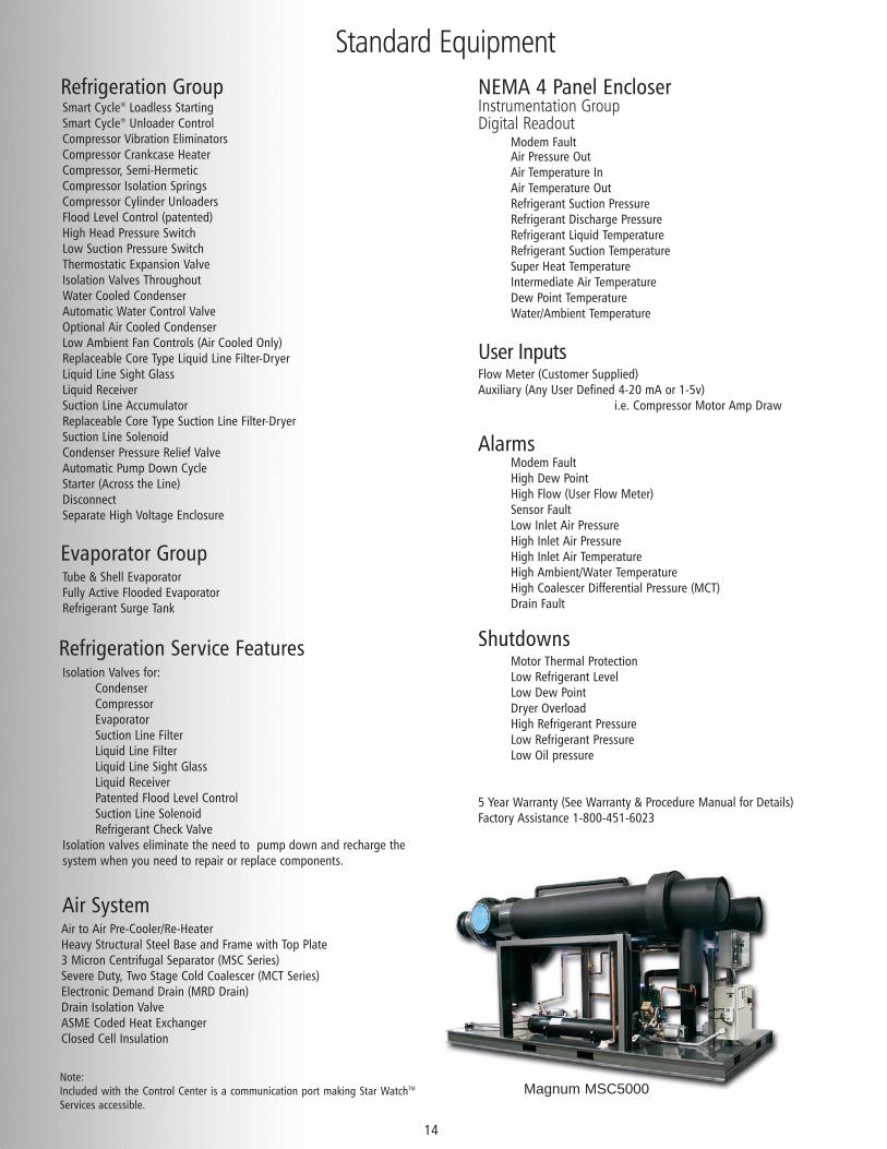
Magnum MSC5000Note:Included with the Control Center is a communication port making Star WatchTM
Services accessible.
Isolation Valves for:CondenserCompressorEvaporatorSuction Line FilterLiquid Line FilterLiquid Line Sight GlassLiquid ReceiverPatented Flood Level ControlSuction Line SolenoidRefrigerant Check Valve
Isolation valves eliminate the need to pump down and recharge thesystem when you need to repair or replace components.
Available Equipment
15
Open Drive Compressor100% Back-up Compressor50% Back-up Compressor (MSC/MCT 12000 & larger)404A RefrigerantAlternate Refrigerants
Refrigeration Options
Stainless Steel Exchangers and/or Piping (304L or 316L)Low Pressure Drop Air System (<3 psid)Cupro-Nickle Tube
Air System Options
Air CooledCupro-Nickel Tubes (Water Cooled)Stainless Steel Tubes (Water Cooled)Air Cooled w/ Water Cooled AssistedRemote Air Cooled (Std 4000-Larger)Heresite Coated Air Cooled Condenser
Condenser Options
Particulate PrefilterCoalescing AfterfilterSpare ElementCold Point Mist Eliminator Ports3 Valve By-Pass Piping (Pre-Assembled, Shipped Loose)Customized (reduced footprint, connection size and
Location, Mirror Image, Etc.)
Package Options
Fused DisconnectJIC Electrical WiringZ Purge Control PanelAny VoltageHeat TracingLow Ambient
Electrical Options
StarWatchTM ServicesDual Hour MetersRemote Control Panel4-20 mA Output For Dew PointPLC InterfaceAudible Alarm
Instrumentation Options
200 MAWP300 MAWP500 MAWP700 MAWP
Pressure Options
Lifting LugsFactory Supervised Start-UpExport PackageSpecial Paint ColorCertified “As Built” Drawings
Miscellaneous Options
Landfill Gas DryerDigester Gas DryerAir and Gas CoolersChilled Water Dryers
Specialty Magnum Dryers
With Airtek your options are unlimited, consult the factory for your specialrequirements.
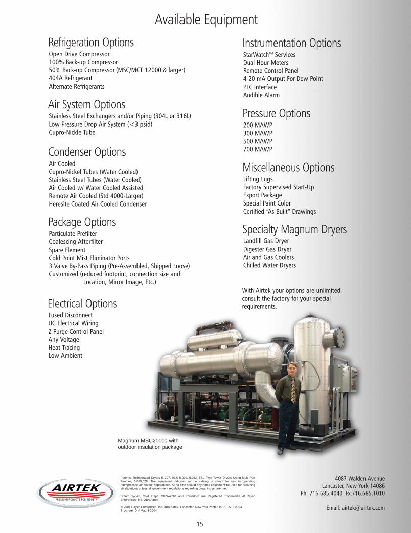
Magnum MSC20000 with outdoor insulation package
4087 Walden AvenueLancaster, New York 14086
Ph. 716.685.4040 Fx.716.685.1010
Email: [email protected]
Patents: Refrigerated Dryers 5, 207, 072; 5,099, 5,062, 571. Twin Tower Dryers Using Multi PortFeature, 6,099,620. The equipment indicated in the catalog is meant for use in operating“compressed air driven” apparatuses. At no time should any Airtek equipment be used for breathingair situations unless all government regulations regarding breathing air are met.
Smart Cycle®, Cold Trap®, StarWatch® and Powerloc® are Registered Trademarks of RaycoEnterprises, Inc. DBA Airtek
© 2004 Rayco Enterprises, Inc. DBA Airtek, Lancaster, New York Printed in U.S.A. 3-2004Brochure ID # Mag 3-2004
AIRTEKPREMIUM PRODUCTS FOR INDUSTRY

www.airtek.com
CAGI
CO
MPRESSED
A
IR
AND
GAS INST
IT
UTE
R
Member