Embed Size (px)
Citation preview
1st Regional and 8th Iranian Tunneling Conference هشتمين آنفرانس تونل 18.-20.05.2009, Tehran, Iran 31-29 تهران–مدرس دانشگاه تربيت– 1388ارديبهشت
Abstract:Alborz Service Tunnel is the longest tunnel (6.4 km) along Tehran Shomal Freeway. A service tunnel with diameter 5.20 m is excavated in advance of two main tunnel tubes to be excavated subsequently. The purpose of the service tunnel is for site investigation, drainage of the rock mass, providing access for main tunnel excavations and for service, ventilation and drainage during operation of the complete tunnel system.
Site investigation for the service tunnel was done by surface mapping and surface geoelectrical survey, but without direct investigations like core drilling, since the overburden is up to 850 m. During excavation by open gripper TBM, the following major extraordinary difficulties have been encountered: methane gas, squeezing ground and blocked cutter head and TBM shield, multiple fault zones with large crown instabilities, karst with water in gypsum / anhydritic rock, water ingress of more than 550 l/s over months and H2S gas of >100 ppm, released from water and from dry rock.
The paper describes the measures taken to negotiate these difficulties. They include modifications on the ventilation system, adapted working procedures at CH4 gas, manual excavation of bypasses around the shield and the cutter head, foam and cement injections for rock stabilization, extensive drainage measures to handle the water quantities and various protective equipment against cold water and H2S gas.
Keywords: TBM, water ingress, H2S, CH4, Alborz, karst
1. Introduction The Tehran Shomal Freeway project in Iran is a new freeway to connect the
capital Tehran with the city of Chalus at the Caspian Sea in the North. The total length is 121 km. Currently traffic runs on small roads passing the Alborz mountains and the journey takes 5 - 6 hours. Upon completion of the project the
Alborz Service Tunnel in Iran: TBM Tunnelling in Difficult Ground Conditions and its Solutions
Wenner, Dieter, Eng.-Geol. MSc, Rock Mech. Eng. MSc, Project Manager Amberg Engineering Ltd., Trockenloostr. 21, 8105 Regensdorf, Switzerland [email protected]
Wannenmacher, Helmut, Engineering Geology MSc, Project Manager Geotechnics Amberg Engineering Ltd., Rheinstr. 4, 7320 Sargans, Switzerland [email protected]
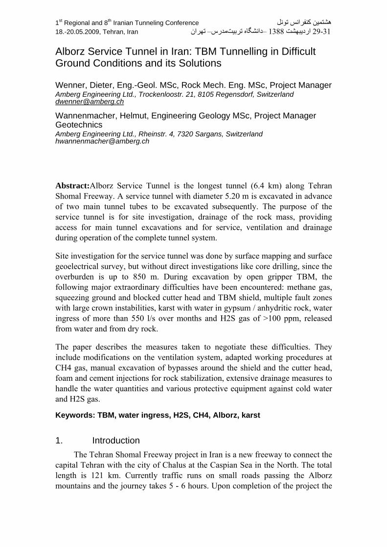
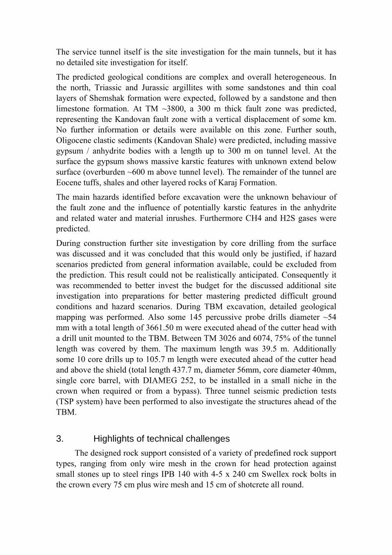
travelling time will reduce to less than 2 hours with an overall higher capacity. The freeway alignment has more than 30 twin tunnels for double lanes. The Alborz Tunnel will be the longest of these with a length of 6400 m at an altitude of 2400 m, see Fig. 1. The paper covers the TBM excavation of the service tunnel.
The service tunnel is located between the main tunnel tubes and is used for site investigation, drainage and as access for the main tunnel construction to commence soon, as well as for ventilation and later as a service tunnel for the main tunnels during operation. The length of the service tunnel is 6387 m, including 314 m of drill and blast tunnel previously excavated from the south portal and 46 m for the TBM starting tube from the N-portal. An open gripper hard rock TBM from Wirth (5,2 m diameter) has started excavation at TM 46 from north portal (= TM 0) with constant positive gradient (~1%). The maximum overburden is in the range of 850 m.
First TBM excavation took place on 06.09.2004 during erection and commissioning of the TBM. Productive excavation started on 06.02.2005 at TM 122. On 03.02.2009 after some 48 months, break through into the S-portal heading was celebrated at TM 6073. During this time (1459 days), excavation took place during 919 days (63%), resulting in an overall average of 6.48 m/d during days with advance. The maximum advance was 30.47 m/day, 110.96 m/week and 389.43 m/month.
Fig. 1: Project Location of Alborz Service Tunnel
2. Site Investigation
Site investigation for the service tunnel included a geological surface mapping, a geoelectric resistivity survey along the alignment from the surface and some index laboratory tests on rock samples. No boreholes have been drilled.
The service tunnel itself is the site investigation for the main tunnels, but it has no detailed site investigation for itself.
The predicted geological conditions are complex and overall heterogeneous. In the north, Triassic and Jurassic argillites with some sandstones and thin coal layers of Shemshak formation were expected, followed by a sandstone and then limestone formation. At TM ~3800, a 300 m thick fault zone was predicted, representing the Kandovan fault zone with a vertical displacement of some km. No further information or details were available on this zone. Further south, Oligocene clastic sediments (Kandovan Shale) were predicted, including massive gypsum / anhydrite bodies with a length up to 300 m on tunnel level. At the surface the gypsum shows massive karstic features with unknown extend below surface (overburden ~600 m above tunnel level). The remainder of the tunnel are Eocene tuffs, shales and other layered rocks of Karaj Formation.
The main hazards identified before excavation were the unknown behaviour of the fault zone and the influence of potentially karstic features in the anhydrite and related water and material inrushes. Furthermore CH4 and H2S gases were predicted.
During construction further site investigation by core drilling from the surface was discussed and it was concluded that this would only be justified, if hazard scenarios predicted from general information available, could be excluded from the prediction. This result could not be realistically anticipated. Consequently it was recommended to better invest the budget for the discussed additional site investigation into preparations for better mastering predicted difficult ground conditions and hazard scenarios. During TBM excavation, detailed geological mapping was performed. Also some 145 percussive probe drills diameter ~54 mm with a total length of 3661.50 m were executed ahead of the cutter head with a drill unit mounted to the TBM. Between TM 3026 and 6074, 75% of the tunnel length was covered by them. The maximum length was 39.5 m. Additionally some 10 core drills up to 105.7 m length were executed ahead of the cutter head and above the shield (total length 437.7 m, diameter 56mm, core diameter 40mm, single core barrel, with DIAMEG 252, to be installed in a small niche in the crown when required or from a bypass). Three tunnel seismic prediction tests (TSP system) have been performed to also investigate the structures ahead of the TBM.
3. Highlights of technical challenges
The designed rock support consisted of a variety of predefined rock support types, ranging from only wire mesh in the crown for head protection against small stones up to steel rings IPB 140 with 4-5 x 240 cm Swellex rock bolts in the crown every 75 cm plus wire mesh and 15 cm of shotcrete all round.
During excavation of the service tunnel, an extraordinary variety of technical challenges related to adverse geological condition has been faced. These include presence of methane gas (CH4), high quantity water ingress even inrush of running ground, squeezing conditions resulting in blockage of the TBM shield and cutter head, a major karstic fault zone at the start of an anhydrite section and finally multiple gases in high concentrations (hydrogen sulphide (H2S), CH4 and carbon monoxide (CO)). To overcome the overall adverse condition various bypass tunnels were excavated to continue the excavation.
Some of the hazard types encountered and in particular the measures taken to negotiate these conditions are subsequently discussed.
4. Description and Measures
4.1. Bypass The excavation of a bypass tunnel as one of the last remaining possibilities
is required when the shield is stuck under severe squeezing conditions or the cutter head is blocked and the blockage can not be removed from inside the cutter head anymore.
Blockage of the cutter head often occurred in collapsing voids, when big blocks squeezed or blocked the scraper openings, or where fault zone or karstic void material at the transition into anhydrite formations collapsed against the cutter head face and friction was excessively increased. Collapsing voids were often created by too much mucking for too less advance. This created over excavation and progressive failure in the crown. When this mechanism has not been detected in due time, the void increased until it collapsed.
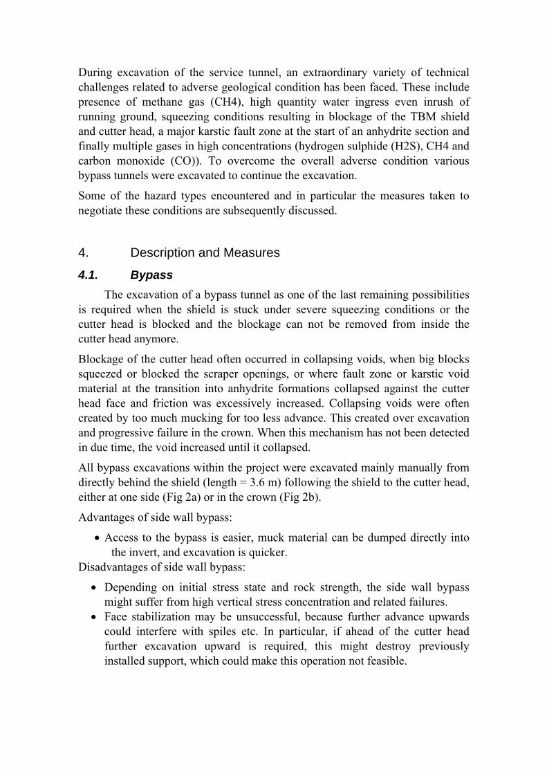
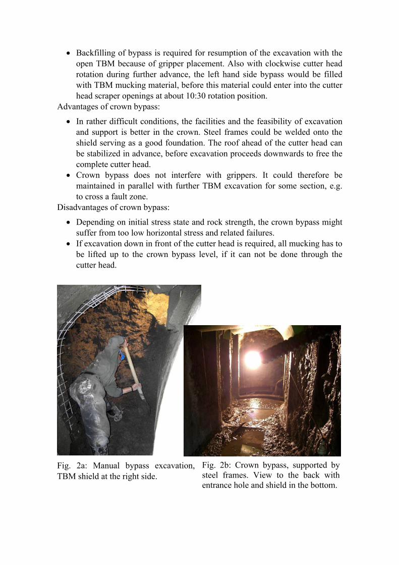
All bypass excavations within the project were excavated mainly manually from directly behind the shield (length = 3.6 m) following the shield to the cutter head, either at one side (Fig 2a) or in the crown (Fig 2b).
Advantages of side wall bypass:
• Access to the bypass is easier, muck material can be dumped directly into the invert, and excavation is quicker.
Disadvantages of side wall bypass:
• Depending on initial stress state and rock strength, the side wall bypass might suffer from high vertical stress concentration and related failures.
• Face stabilization may be unsuccessful, because further advance upwards could interfere with spiles etc. In particular, if ahead of the cutter head further excavation upward is required, this might destroy previously installed support, which could make this operation not feasible.
• Backfilling of bypass is required for resumption of the excavation with the open TBM because of gripper placement. Also with clockwise cutter head rotation during further advance, the left hand side bypass would be filled with TBM mucking material, before this material could enter into the cutter head scraper openings at about 10:30 rotation position.
Advantages of crown bypass:
• In rather difficult conditions, the facilities and the feasibility of excavation and support is better in the crown. Steel frames could be welded onto the shield serving as a good foundation. The roof ahead of the cutter head can be stabilized in advance, before excavation proceeds downwards to free the complete cutter head.
• Crown bypass does not interfere with grippers. It could therefore be maintained in parallel with further TBM excavation for some section, e.g. to cross a fault zone.
Disadvantages of crown bypass:
• Depending on initial stress state and rock strength, the crown bypass might suffer from too low horizontal stress and related failures.
• If excavation down in front of the cutter head is required, all mucking has to be lifted up to the crown bypass level, if it can not be done through the cutter head.
Fig. 2a: Manual bypass excavation, TBM shield at the right side.
Fig. 2b: Crown bypass, supported by steel frames. View to the back with entrance hole and shield in the bottom.
The advantages and disadvantages of side wall bypass and crown bypass experienced during the excavation are subsequently discussed for the 5.2 m diameter open TBM and may be found helpful for other projects as well.
There is no general rule, which location should be preferred for a bypass to the cutter head. The best solution always depends on local conditions and targets, which change from case to case.
The bypass can be used for installation of drainage holes, various probe and core drillings, which could stay outside of the profile to be excavated by the TBM later to avoid problems in case of rod lost, and for injections for ground improvement and water flow reduction.
4.2. Gases CH4 was first encountered at TM 1884 and since then occurred
occasionally. CH4 is an explosive gas, lighter than air and odourless. The lower explosive limit (LEL) is at 4.6 vol-% in the atmosphere, corresponding to 100% LEL. The source of CH4 is related to the coal layers in the northern part of the tunnel, which also exist in the central and southern part at greater depth to some extend. Since no major storage rocks exist in this area, the risk of quick large quantity inrushes of CH4 was regarded low. Generally CH4 could therefore be controlled with sufficient quantity of ventilation, but particular hazards may develop in confined spaces like over breaks or during and after temporary breakdowns of the ventilation system. The installed capacity was increased and is then sufficient to generate 1.0 to 1.2 m/s air speed in the general body of air behind the TBM.
Alarm levels were set at 10% and 20% LEL in the general body of air. At 10% LEL, all measures must be taken to reduce the gas: local dilution of gas with compressed air or air movers, further increase of ventilation (if possible), suspension of works (probe drilling or TBM excavation) to reduce the release rate, detailed monitoring and reporting. When the concentration exceeded 20% LEL immediate and controlled evacuation of the complete tunnel was required. This included collection of all personnel including head count, switching off the TBM main electrical power supply and starting an explosive proof ventilation system (when available).
As a preventive measure some transport facilities must always be available at the TBM within potentially gas bearing ground. At times where this was not possible, e.g. when the mucking train runs out, no rock bolt or probe drilling works were allowed, which could initiate sudden gas ingress.
All hot works (welding, grinding) required special permission by the safety personnel, including gas check. Evacuation trainings were executed in regular intervals.
Special procedures for reentering the tunnel after evacuation were defined and had to be followed strictly, e.g. tunnel ventilation for defined time, entering with gas detector (with checking gas concentration at the front end of a train) for checking the conditions, also including confined spaces like electrical cabinets. Depending on the local gas concentrations further flushing by compressed air may be required.
Only upon fulfilment of all requirements and procedures the main power supply was allowed to be switched on again and works could continue. Also special procedures were required for entering the confined space, e.g. the cutter head.
Probe drills ahead of the cutter head and vertically into the crown were used to systematically check for gas and eventually drain it in a controlled way, before these gas bearing joints were intersected by the TBM excavation. Shotcreting of the rock surface can help to reduce the flow of gases into the tunnel.
H2S was first encountered at TM 2967 and since then occurred several times. H2S is a gas heavier than air and with strong smell of rotten eggs. The main hazards are related to its toxicology and corrosive property to metals. It can be identified by smelling below 1 ppm. The 8 hours occupational exposure limit is 10 ppm, for short times (15 min), 15 ppm is acceptable. Above 15 ppm full face masks with filters were used. This restricted the ability to work to a great extend. Also filters could not be used without further protection, where water squirts around under high pressure: if it enters into the filter, the filter will be blocked immediately.
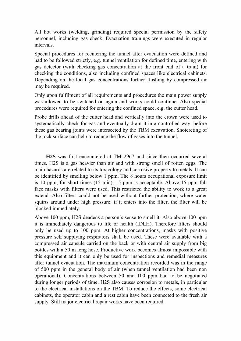
Above 100 ppm, H2S deadens a person’s sense to smell it. Also above 100 ppm it is immediately dangerous to life or health (IDLH). Therefore filters should only be used up to 100 ppm. At higher concentrations, masks with positive pressure self supplying respirators shall be used. These were available with a compressed air capsule carried on the back or with central air supply from big bottles with a 50 m long hose. Productive work becomes almost impossible with this equipment and it can only be used for inspections and remedial measures after tunnel evacuation. The maximum concentration recorded was in the range of 500 ppm in the general body of air (when tunnel ventilation had been non operational). Concentrations between 50 and 100 ppm had to be negotiated during longer periods of time. H2S also causes corrosion to metals, in particular to the electrical installations on the TBM. To reduce the effects, some electrical cabinets, the operator cabin and a rest cabin have been connected to the fresh air supply. Still major electrical repair works have been required.
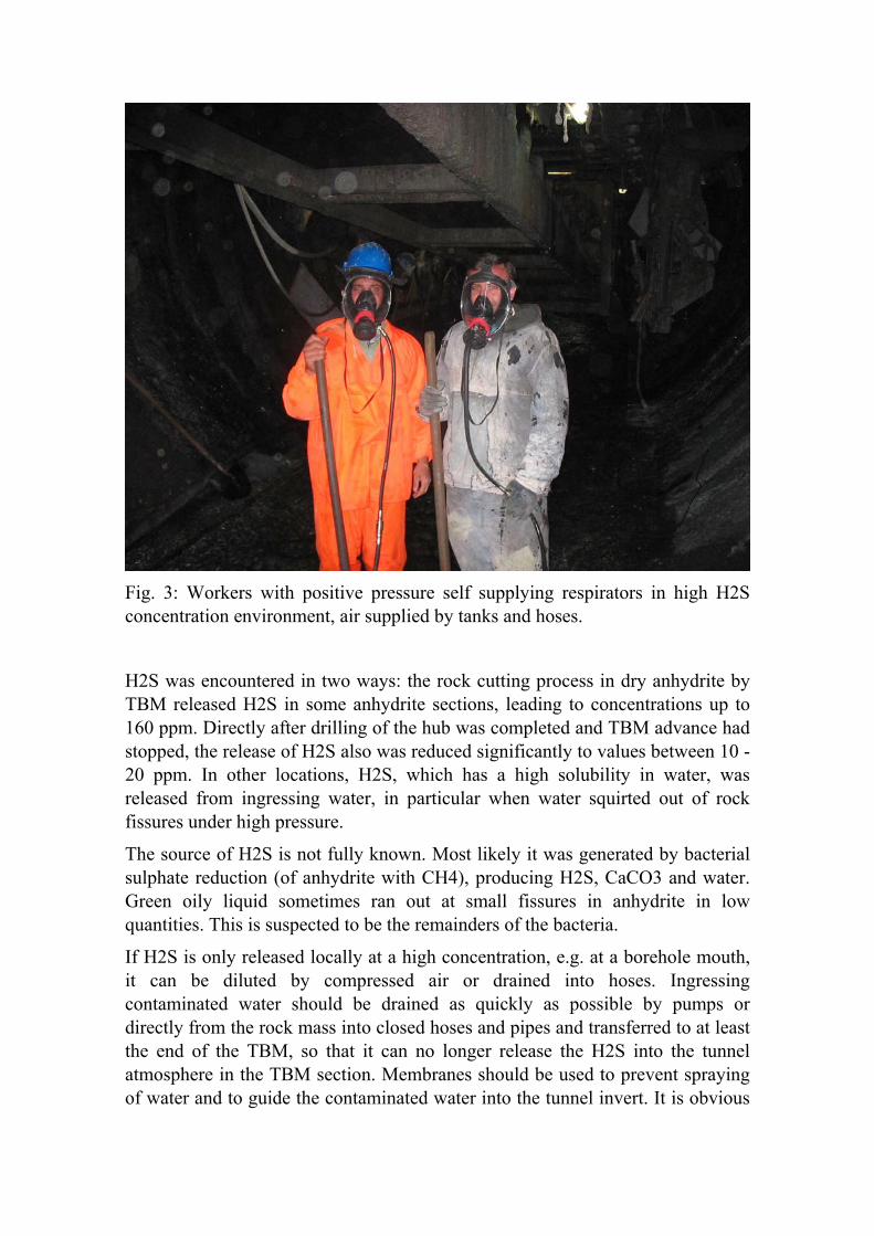
Fig. 3: Workers with positive pressure self supplying respirators in high H2S concentration environment, air supplied by tanks and hoses.
H2S was encountered in two ways: the rock cutting process in dry anhydrite by TBM released H2S in some anhydrite sections, leading to concentrations up to 160 ppm. Directly after drilling of the hub was completed and TBM advance had stopped, the release of H2S also was reduced significantly to values between 10 - 20 ppm. In other locations, H2S, which has a high solubility in water, was released from ingressing water, in particular when water squirted out of rock fissures under high pressure.
The source of H2S is not fully known. Most likely it was generated by bacterial sulphate reduction (of anhydrite with CH4), producing H2S, CaCO3 and water. Green oily liquid sometimes ran out at small fissures in anhydrite in low quantities. This is suspected to be the remainders of the bacteria.
If H2S is only released locally at a high concentration, e.g. at a borehole mouth, it can be diluted by compressed air or drained into hoses. Ingressing contaminated water should be drained as quickly as possible by pumps or directly from the rock mass into closed hoses and pipes and transferred to at least the end of the TBM, so that it can no longer release the H2S into the tunnel atmosphere in the TBM section. Membranes should be used to prevent spraying of water and to guide the contaminated water into the tunnel invert. It is obvious
that high concentrations can not be negotiated by a realistic increase of ventilation capacity. The tunnel was regularly evacuated when the concentration exceeded 100 ppm.
Generally sufficient numbers of mobile gas detectors must be available, regularly calibrated and used, in particular during any drilling operation (TBM, rock bolts, probe drilling). Tunnel workers must be informed about the hazards, receive medical checks and approval to use masks, trained in the use of masks and other breathing equipment. Personal protective equipment (masks and filters) must be available in sufficient quantity and stock. Fresh air shall be guided to typical working locations along the TBM, e.g. the operator’s cabin, the invert section where rails are placed etc.
When CH4 or H2S was detected in joints in probe drills far ahead of the cutter head, these joints were tried for cement grouting in order to reduce the conductivity for the gas in the rock mass. In addition, about 6 m long gas drainage holes were drilled in the close vicinity of the cutter head to drain the gas.
Presence of hydrogen cyanide (HCN) had been tested and found to be not present. In another tunnel project in Iran, where also high concentrations of H2S were encountered, also HCN had been detected in significant quantities. Carbone monoxide (CO) had also been detected in one section of the tunnel in concentrations above 500 ppm, where the 8 hours occupational exposure limit is 30 ppm. The tunnel was evacuated, since the available filters did not provide any protection against CO.
By implementing and strictly following the above described procedures, it was possible to execute the works without major accidents. But longer time delays and significantly reduced progress rates had to be accepted.
4.3. Water Ingress The northern section of the tunnel had only low water flow. At TM 2582, a
first significant ingress was encountered with >90 l/s, which increased to ~125 l/s during further advance. At TM 2967 a further water ingress had to be faced, adding ~110 l/s to the total flow rate and releasing H2S (up to 25 ppm).
At TM 3015, some initial 110 l/s rushed into the tunnel together with estimated 100 m3 of mud and stone material and also releasing H2S (up to 60 ppm). This represented a fault zone with karstic void fillings when entering into the first anhydrite section. Over the following two months, the total water quantity from the tunnel reduced from 290 to 50 l/s. The other end of this anhydrite was unproblematic with respect to water ingress and did not cause any tunnelling problems.
Fig. 4: Main water ingress with estimated 800 l/s in the TBM backup with rails installed.
The main water ingress occurred at TM 4524 in a fault zone: the total tunnel flow at the portal increased from 60 l/s to initial 690 l/s recorded (~800 l/s estimated, fig. 4) with high concentration of H2S (>100 ppm). After a first waiting period for water reduction, TBM excavation through the water bearing fault zone was proceeded. The total water flow slowly reduced to 380 l/s over eight months. During the first 3 months, works could only be executed with masks. In mid August 2008, again a karstic fault zone was hit at the end of the southern anhydrite section. It initially added 220 l/s to make a total flow of 600 l/s, which quickly reduced to 450 l/s within four weeks. Finally the total water flow continued to reduce to 270 l/s over another 4.5 month until break through and reduction is expected to further continue.
The main hazards related to these water ingresses and inrushes are the release of H2S from the water and the inrush of material and subsequently collapse of washed out voids eventually leading to blockage of the cutter head. Also working conditions for workers with cold water squirting everywhere are harsh, especially in winter times and temperatures down to -15 °C and the requirement to run the ventilation with full speed because of the gases. Neoprene wet and dry suits like for divers have been used under these conditions for protection. Further hazards
are related to the bad effect of water on various electrical installations and various high voltage cables being submerged under water.
The ingressing water also affected the transportation system facilitated by trains. Sleepers for the rail tracks were placed directly on the bored invert or invert shotcrete. No invert segments had been used. Water drainage was by free flow in the invert to the portal. While an additional 400 mm drainage pipe has been installed on the tunnel wall, it was never possible to utilize it in a reasonable way, since no suitable high performance waste water pumps were available on the local market in Iran, because of overall political sanctions. One of the main problems was the sedimentation of fine materials in the invert, blocking rails and causing derailments. This happened mainly in local depressions of the vertical alignment and at the upstream side of a California crossing, which effectively act like a sedimentation pond. Railway traffic on rails covered by water caused no significant problems. Just more maintenance was required for the rolling stock.
Most water ingresses could be identified in advance by probe drillings. But attempts to grout these zones in advance to reduce the water flow had never been successful. The reasons are mainly related to the high pressures and flow rates together with limited availability of equipment like preventer or packers and experienced contractor’s personnel for these works.
Due to these circumstances it was finally always decided to drain the water, considering that one of the main tasks of this service tunnel is to drain the rock mass for the excavation of the main freeway tunnels.
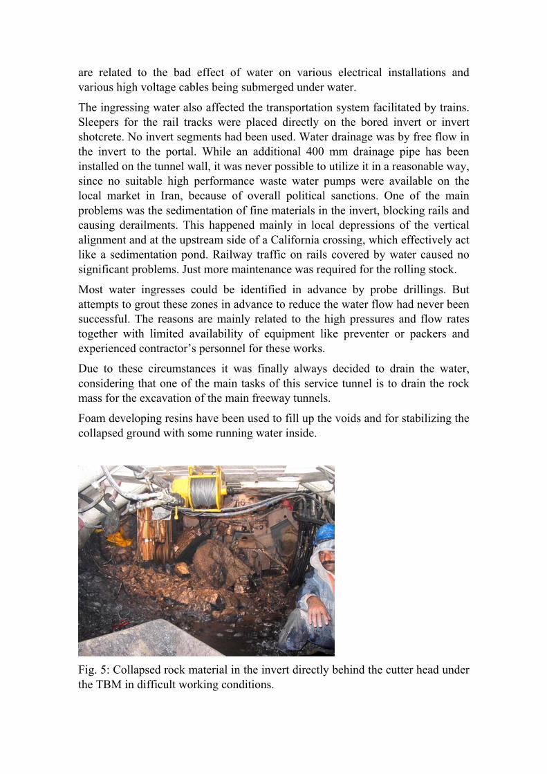
Foam developing resins have been used to fill up the voids and for stabilizing the collapsed ground with some running water inside.
Fig. 5: Collapsed rock material in the invert directly behind the cutter head under the TBM in difficult working conditions.
5. Concluding Remarks
A series of extraordinary geological difficulties had to be technically mastered during TBM excavation of the Alborz Service Tunnel in Iran. This has significant influence on the progress rates and the construction schedule as well as on the costs. The hazards and some methods to deal with them have been described in this paper.
However, and most important, all these hazards and difficulties could finally be passed without any major accident or even fatalities. Improvements could be achieved by better preparation for expected problems in advance, in contrast to solving problems “on demand”.