Embed Size (px)
Citation preview
Algorithm for methane number determination for natural gasses
Project Report
June 1999
Algorithm for methane number determination for natura! gasses
Paw Andersen
Danish Gas Tecbnology Centre a/s Hørsholm 1999
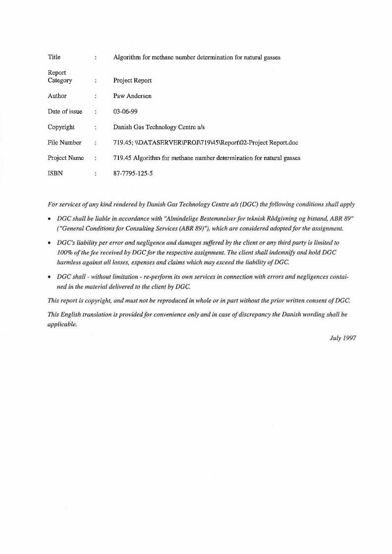
Title
Report Category
Author
Date of issue
Copyright
FileNumber
Project Naroe
ISBN
Algorithin for roethane number deterl)lination for natural gasses
Project Report
Paw Andersen
03-06-99
Danish Gas Technology Centre a/s
719.45; \\DATASERVER\PROJ\719\45\Report\02-Project Report.doc
719.45 Algorithm for roethane nurober determination for natural gasses
87-7795-125-5
Forservices ofany kind rendered by Danish Gas Teclmology Centre a/s (DGC) thefollowing conditions shall apply
• DGC shall be liable in accordance with "Almindelige Bestemmel er for teknisk Rådgivning og bisra.rul, ABR 89"
(''General Conditions for Consulting Services (ABR 89)"), which are considered adoptedjor the assignment.
• DGC's liability per error and negligence and damages suffered by the client or an.y third party is limited to
l 00% o f the fee received by DGC for the respective assignment. The client shall indemnify and hold DGC
harmless against all losses, expenses and claims which may exceed the liability of DGC.
• DGC shall - without limitarion - re-peiform its own services in comzection with en·ors and negligences cof!lai
ned in the material delivered to the client by DG C.
This repart is copyright, and must not be reproduced in whole or in part without the prior written consent ofDGC.
This Englis h translation is provid ed for convenience only and in case of discrepancy t h e Danis h wording s hall be
applicable.
July 1997
DGC-report 1
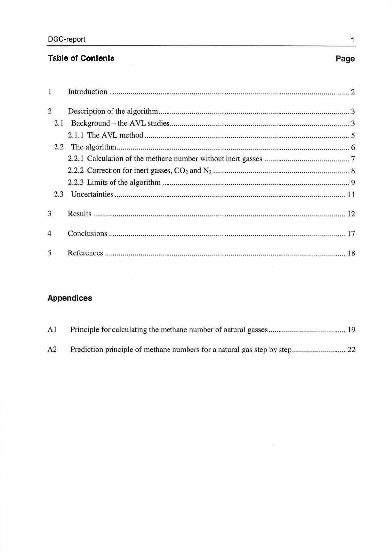
Table of Contents Page
l Introduetion ........................ ..... .. ........ ......... ... .. ... ..................................................... .. ......... .. 2
2 Description of the algorithm ................................................................................................. 3
2.1 Background- the AVL studies ........................................................................................... 3
2. 1.1 The AVL n1ethod ...... .. .............. ..... .............. ........ .. ..... ................................................ 5
2.2 The algorithn1 .................................................... ............ ........................................ .............. 6
2.2.1 Calculation of the methane number without inert gasse . ................... .......... .............. 7
2.2.2 Cerreetion for inert gas es, C02 and N 2 ........ . . ... .... ..... ..... .. ........................................ 8
2.2.3 irnits o f the algorithrn ............................................................................................... 9
2.3 Uncertainties ..................................................................................................................... 11
3 Results ................................................................................................................................ 12
4 Conclusion .... .................................................................................................................... 17
5 References .......................................................................................................................... 18
Appendices
Al Princip le for calculating the ruethane number of naturaJ gasses ....................................... 19
A2 Prediction principle of roethane numbers for a natural gas step by tep ........................... 22
DGC-report 2
1 Introduetion
So far, DGC has calculated the roethane number for the Danish natura} gas
quality using an algorithm developed by DGC. Since the introduetion of gas
from the Harald field and the ensuing changes to the Danish natura} gas
composition, the sphere of application of the algorithm has been exceeded.
This report describes a new algorithm for determination of the roethane
number for natura! gasses.
On the basis of the new algorithm a program has been developed to
calculate the roethane number. The program together withauser manual can
be requested from Danish Gas Technology Centre.
Per Gravers Kristensen, DGC, has developed the new algorithm and J an
Jensen, DGC, has performed quality assurance of the report.
Hørsholm, June 1999
~~ Paw Andersen
Project Manager
DGC-report 3
2 Description of the algorithm
There is no present standard for determining the methane number for gas
mixtures. Nevertheless, practically most of the recent work with gasses
tendency for knocking refer to the very profound studies performed at AVL
in the late sixties /1/. This new algorithm is also basedon these AVL stud
ies.
2.1 Background - the AVL studies
In the AVL w ork a test en gine o f the same type as the en gines used for
octane number determination was used to determine the gasses' relative
tendency for knocking. As for petrol's octane number /2/, /3/ the scale for
the gasses is relative. The definitions are that pure methane has a methane
number o f l 00 and pure hydrogen has a methane number o f O.
The AVL study Il/ ineludes the components CH4, C2H4, C~6, C3H6, C3Hs,
n-C4H10, H2, C02, N2 and H2S in binary and temary comperrent mixtures. In
addition, some measurements have been made for a lirnited number of
natural gasses. Frimarily all the AVL Il/ data are available as temary
diagrams, as shown in Pigure 2.1 and Pigure 2.2. For further information on
the AVL studies see 111.
DGC-report
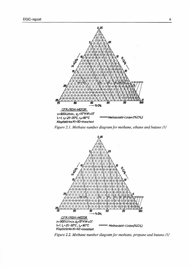
CFR IRDH-MOTOR
n·900U/min .• ~y·15°KWv.OT '11.•1, ts•25-30°C, tw-80°C -Methanzahi-Linien(%Cf4) Klopfstiirke K/• 50• konstant
Pigure 2.1. Methane number diagramfor methane, ethane and butane Il/
CFR/RDH-MOTOR n=900U/min. ct.·1SOKWv.OT ')...f, ts •25-30°C, fw·B0°C - Methanzahi-Linien(%Cf4) Klopfsti:irke K/•50 •konstant
4
Pigure 2.2. Methane number diagramfor methane, propane and butane Il/
DGC-report 5
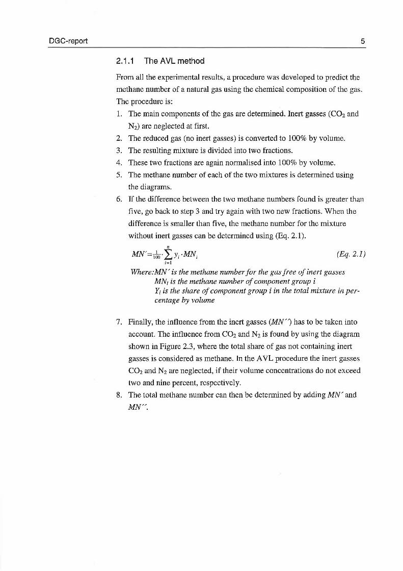
2.1.1 The AVL method
From all the experimental results, a procedure was developed to predict the
methane number of a natural gas using the chemical composition of the gas.
The procedure is:
l. The main components of the gas are determined. Inert gasses (C02 and
N2) are neglected at first.
2. The reduced gas (no inert gasses) is converted to 100% by volume.
3. The resulting mixture is divided into two fractions.
4. These two fractions are again normalised in to l 00% by volume.
5. The methane number of each o f the two mixtures is determined using
the diagrams.
6. lf the difference between the two methane numbers found is greater than
five, go back to step 3 and try again with two new fractions. When the
difference is smaller than five, the methane number for the mixture
without inert gasses can be determined using (Eq. 2.1). n
MN'= 16o·LY; ·MN; (Eq. 2.1) i=l
Where:MN' is the methane number for the gas free of inert gasses MN; is the methane number of component group i Y; is the share of component group i in the total mixture in percentage by volume
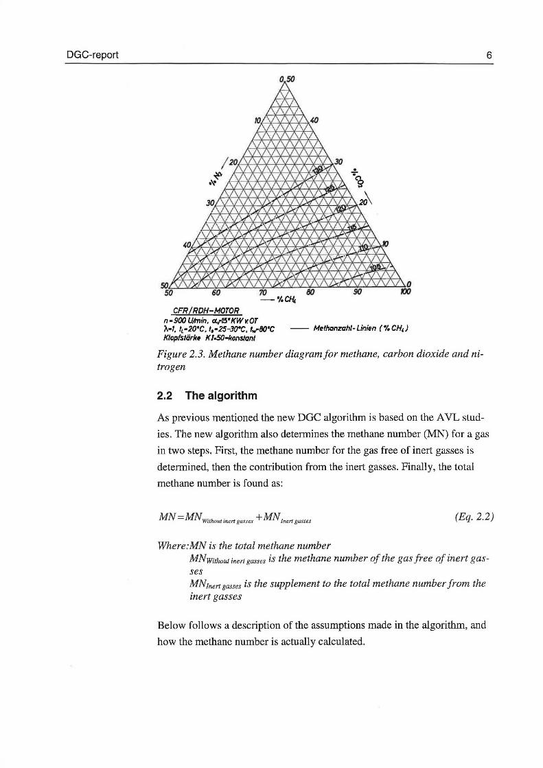
7. Finally, the influence from the inert gasses (MN") has to be taken into
account. The influence from C02 and N2 is found by using the diagram
shown in Pigure 2.3, where the total share of gas not containing inert
gasses is considered as methane. In the AVL procedure the inert gasses
C02 and N2 are neglected, if their volume concentrations do not exceed
two and nine percent, respectively.
8. The total methane number can then be determined by adding MN' and
MN".
DGC-report 6
CFR /RDH-MOTOR n-900 Uhnin, «.t-15'KWv.OT 'A-1. tL·20'C. t.·25-30'C, tvrBO'C -- Methanzahi-Linien (%CH,) Klopfstiirke K /.SO-konstant
Figure 2.3. Methane number diagramfor methane, carbon dioxide and nitrogen
2.2 The algorithm
As previous menticned the new DGC algorithm is based on the AVL stud
ies. The new algorithm also determines the methane number (MN) for a gas
in two steps. First, the methane number for the gas free of inert gasses is
determined, then the contribution from the inert gasses. Finally, the total
methane number is found as:
MN = MN Without inen gasses + MNinen gasses (Eq. 2.2)
Where:MN is the total methane number MNwithout inert gasses is the methane number of the gas free of inert gasses MNrnert gasses is the supplement to the total methane number from the inert gasses
Below follows a description of the assumptions made in the algorithm, and
how the methane number is actually calculated.
DGC-report 7
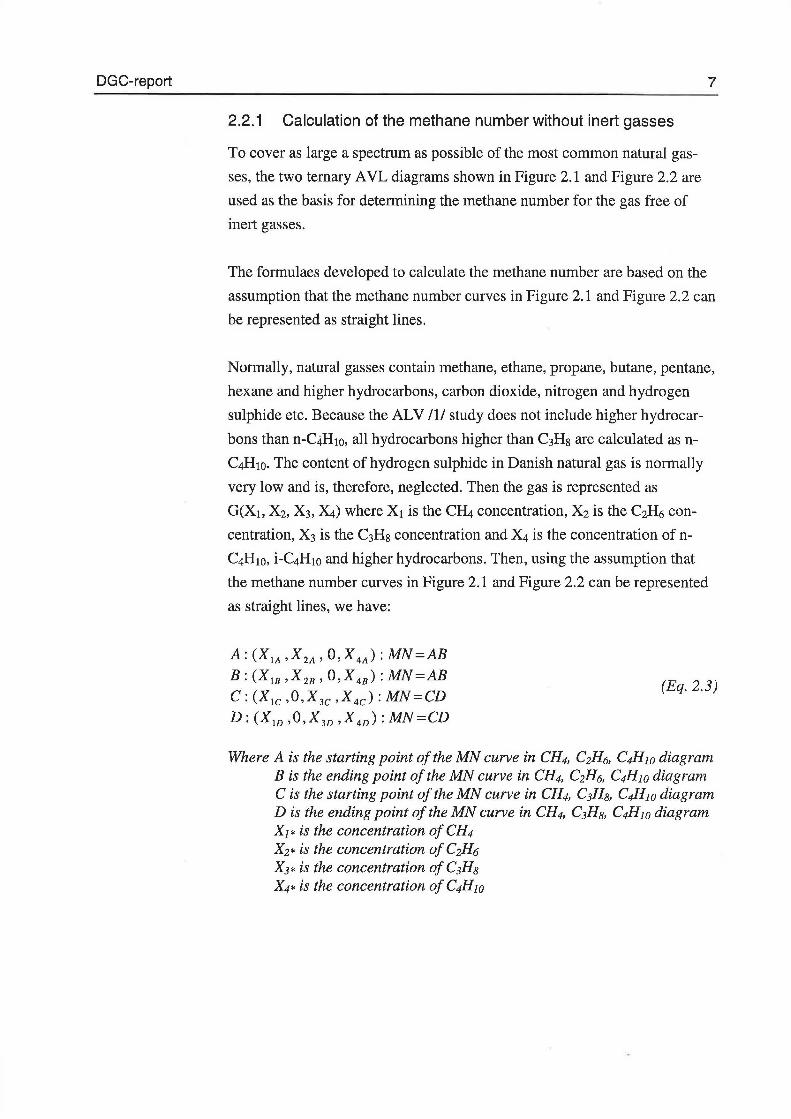
2.2.1 Calculation of the methane number without inert gasses
To cover as large a spectrum as possible of the most common natural gas
ses, the two temary AVL diagrams shown in Figure 2.1 and Figure 2.2 are
used as the basis for determining the methane number for the gas free of
inert gasses.
The formulaes developed to calculate the methane number are based on the
assumption that the methane number curves in Figure 2.1 and Figure 2.2 can
be represented as straight lines.
Normally, natural gasses contain methane, ethane, propane, butane, pentane,
hexane and higher hydrocarbons, carbon dioxide, nitrogen and hydrogen
sulphide etc. Because the ALV /1/ study does not inelude higher hydrocar
bons than n-CiHIO, all hydrocarbons higher than C3Hs are calculated as n
C4HIO. The content of hydrogen sulphide in Danish natural gas is normally
very low and is, therefore, neglected. Then the gas is represented as
G(X1, X2, X3, X4) where X1 is the CH4 concentration, X2 is the C~6 con
centration, X3 is the C3H8 concentration and X4 is the concentration of n
C4H10, i-C4H10 and higher hydrocarbons. Then, using the assumption that
the methane number curves in Figure 2.1 and Figure 2.2 can be represented
as straight lines, we have:
A: (XIA ,X2A' O,X4A): MN=AB B: (X18 ,X28 , o,X48 ): MN=AB
C: (X1c ,O,X3c ,X4c): MN=CD
D: (Xw ,O,X3v ,X4v): MN=CD
(Eq. 2.3)
Where A is the starting point of the MN curve in CH4, C2H6, C4H10 diagram B is the ending point of the MN curve in CH4, C2H6, C4H10 diagram C is the starting point ofthe MN curve in CH4, C1Hs, C4H10 diagram D is the ending point of the MN curve in CH4, C3H8, C4H10 diagram X1 * is the concentration of CH4 X2* is the concentration of C2H6 X3* is the concentration of C1Hs X4* is the concentration of C4H10
DGC-report
Generating two mixtures: E, a mixture of A and B, and F, a mixture of C
and D:
8
E: E AB
F: E BC
Parameter a
Parameter f3 (Eq. 2.4)
Mixing our gas G(X1, X2, X3, X4) as fractions ofE and F we obtain:
G=X ·E+(l-X)·F
and
MN(G)=MN(E)+X ·[MN(F)-MN(E)]
where:
MN(E)=AB MN(F)=CD
(Eq. 2.5)
(Eq. 2.6)
(Eq. 2.7)
Solving this for X, gives the general solution shown in (Eq. 2.6). In Appen
dix Al the derivation of (Eq. 2.6) is given.
x 1
x2A x LB- x28 x,A -X2 (X w -X lA) x3 (X ID - X,c)
X2A - X2B X 3D - X3c x (Eq. 2.8)
X 3D -X3c X2A -X2B
2.2.2 Cerreetion for inert gasses, C02 and N2
As previously mentioned, inert gasses increase the methane number. The
only inert gasses that are taken into account are C02 and N2. To determine
the contribution from the inert gasses C02 and N2, the AVL diagram shown
in Figure 2.3 is used. It has been found that the increased knocking resis
tance due to C02 and N2 can be calculated using a tertiary interpolation ex
pression o f the form:
DGC-report
MZC02&N2 =100-
[%CH 4p ·R111 + [%CHJ2
· [%C02].R112 +
[%CHJ2
· [%Nzl.R113 +
[%CHJ· [%C02]2
·R12z + [%CHJ· [%COzl[%NJ·R123 +
[%CH4 ] • [%Nz]2
·R133 +
[%COz]3
·R222 + [%COz]2
· [%Nz].Rzz3 +
[%coJ [%Nz]2
·Rz33 +[%N z P Rm +
[%CHJ2
·R11 + [%CH4 ]. [%C02].R12 +
[%CHJ [%N2].R13 + [%C02]2
·R22 +
[%C02].[%N2].R23 + [%N2]2 ·R33 +K
9
(Eq. 2.9)
Where:MNc02&N2 is the increase in the methane number caused by C02 and N2 %CH4 is the cantent af CH4, C2H6, C3Hs, C~w in valurne percentage af the gas %C02 is the cantent af C02 in valurne percentage af the gas %N2 is the cantent af N2 in valurne percentage af the gas
RnJ. Rn2, Rn3, Rn2, Rn3, Rn3, R222, R223, R233, R333, Rn. Rn, Rn, R22, R23, R33 and K are canstants where: Rw = 52.25 , Rn2 = 148.40 , Rn2 = 18.68 , R123 = -237.05 , R222 = 48.33 , R223 = 64.18 , R333 = -190.89 , R11 = 29.69 , Rn = 161.54 , R22 = 158.93 , R33 = 302.83 , K = 18.06
2.2.3 Limits of the algorithm
Rn3 = Rn3 = R233 = Rl2 = R23 =
153.84 9.03
440.32 102.83 517.88
The available data that provides the basis for the algorithm also provides the
limits of the algorithm. The calculations can only be made for gasses with a
methane number higher then 45 (without inert gasses). The concentration of
C02 eannot be higher than 30 v ol% and the concentration o f N 2 eannot be
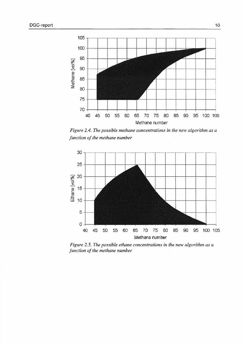
higher than 50 vol%. In Figure 2.4- Figure 2.7 the limits of the calculation
of the methane number without inert gasses are shown.
DGC-report
~ 95 +--!---+---+----+--= '#.
~ 90 +--1---:: Q) c ro L: (j) 2
85
80
75
10
40 45 50 55 60 65 70 75 80 85 90 95 100 105
Methane number
Figure 2.4. The possible methane concentrations in the new algorithm as a
function of the methane number
5
o 40 45 50 55 60 65 70 75 80 85 90 95 100 105
Methane number
Figure 2.5. The possible ethane concentrations in the new algorithm as a function of the methane number
DGC-report
~ 20
~ Q) 15 c ro c.
~ 10
5
o
11
40 45 50 55 60 65 70 75 80 85 90 95 100 105
Methane number
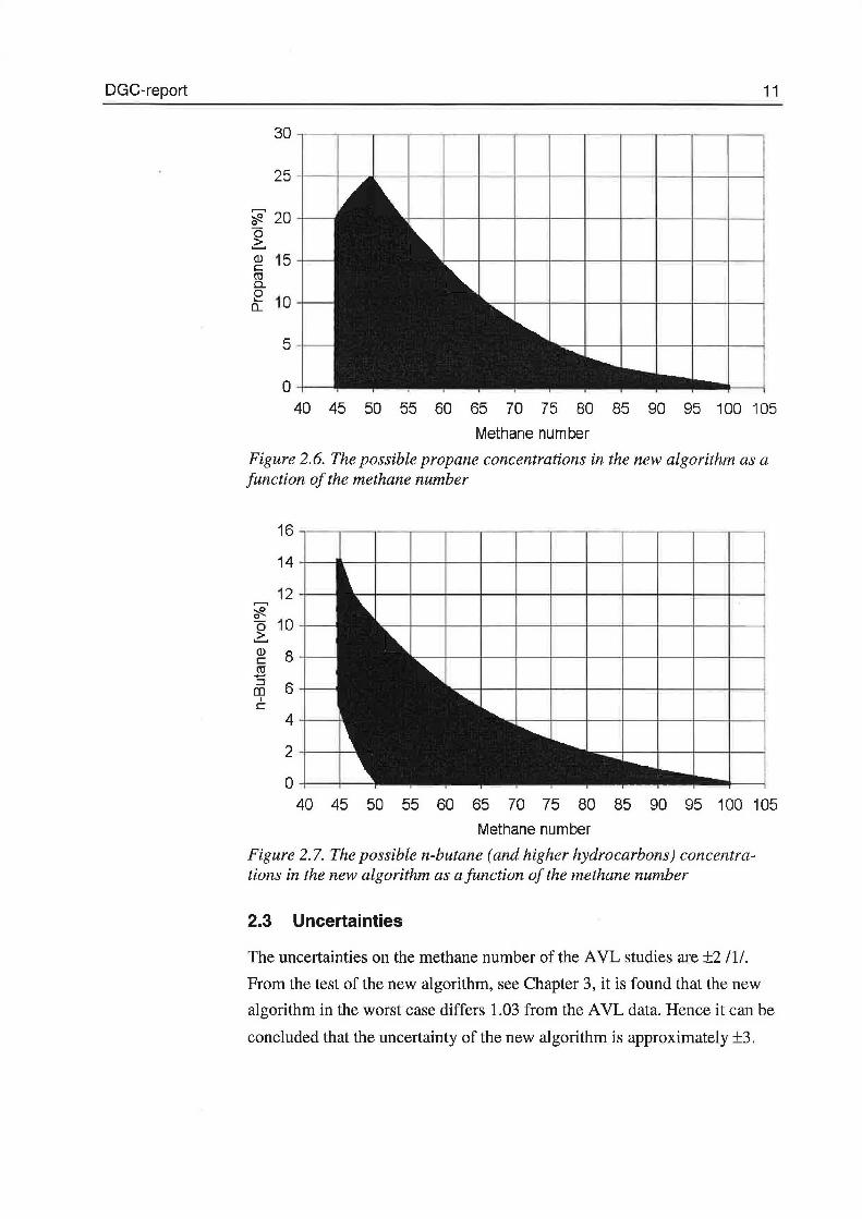
Figure 2.6. The possible propane concentrations in the new algorithm as a function of the methane number
~ o 2:. Q) c ro ..... :J m
l c
16
14
12
10
8
6
4
40 45 50 55 60 65 70 75 80 85 90 95 100 105
Methane number
Figure 2.7. The possible n-butane (and higher hydrocarbons) concentrations in the new algorithm as a function of the methane number
2.3 Uncertainties
The uncertainties on the methane number of the AVL studies are ±2 Il/.
From the test of the new algorithm, see Chapter 3, it is found that the new
algorithm in the worst case differs 1.03 from the AVL data. Renee it can be
concluded that the uncertainty o f the new algorithm is approximately ±3.
DGC-report 12
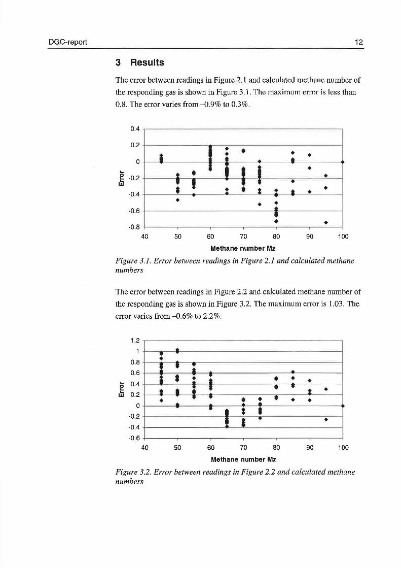
3 Results
The error between readings in Figure 2.1 and calculated methane number of
the responding gas is shown in Figure 3 .1. The maximum error is les s than
0.8. The error varies from -0.9% to 0.3%.
0.4
0.2 • • • • • o • ....
o -0.2 .... .... • w • -0.4 •
• • • -0.6
• -0.8 • 40 50 60 70 80 90 100
Methane number Mz
Figure 3.1. Error between readings in Pigure 2.1 and calculated methane numbers
The error between readings in Figure 2.2 and calculated methane number of
the responding gas is shown in Figure 3.2. The maximum error is 1.03. The
error varies from -0.6% to 2.2%.
1.2
1
0.8
0.6 .... 0.4 o .... ... 0.2 w
o -0.2
-0.4
• : • • • • • å • • • •
t • : • • • t • • • • ~ : • • • • .. ..... • • t • l • • •
-0.6 40 50 60 70 80 90 100
Methane number Mz
Figure 3.2. Error between readings in Figure 2.2 and calculated methane numbers
DGC-report 13
The above results show that the errors introduced by the assumptions that
the methane number curves in Figure 2.1 and Figure 2.2 can be represented
as straight lines is very small.
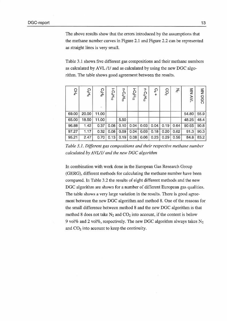
Table 3.1 shows five different gas compositions and their methane numbers
as calculated by AVL Il/ and as calculated by using the new DGC algo
rithm. The table shows good agreement between the results.
() () () ,. :l ,. :l () () z :s: :s: :r 1\) '"' () l () l Ol o 1\)
.... :r :r .... () "'
() + 1\) z z
Ol <X> ~ ....
~ "' ~ :r )> o o 1\) < G) o 1\) r ()
69.00 20.00 11.00 54.80 55.9
65.00 18.50 11.00 5.50 48.25 48.4
96.88 1.42 0.37 0.08 0.10 0.04 0.03 0.04 0.19 0.64 90.65 90.8
97.27 1.17 0.32 0.08 0.09 0.04 0.03 0.18 0.20 0.62 91.3 90.3
95.21 2.47 0.70 0.13 0.19 0.08 0.06 0.23 0.29 0.56 84.8 83.2
Table 3.1. Dif.ferent gas compositions and their respective methane number
calculated by A VUJ/ and the new DGC algorithm
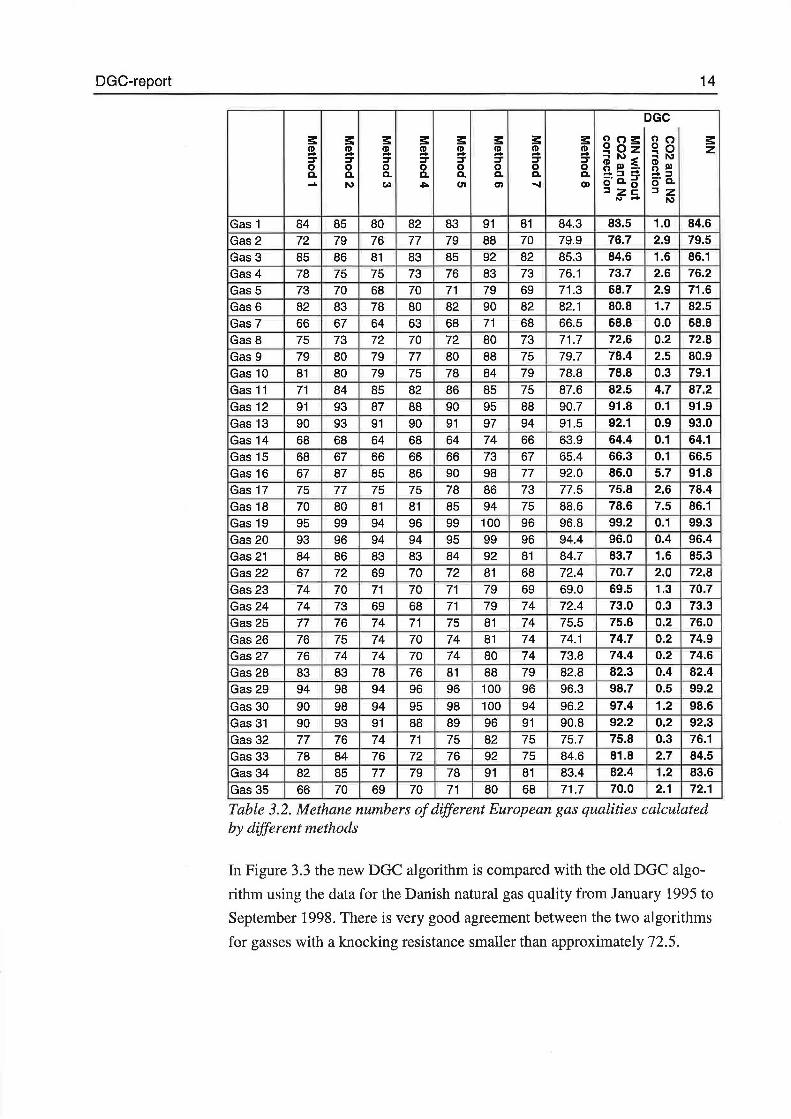
In cernbination with work done in the European Gas Research Group
(GERG), different methods for calculating the methane number have been
compared. In Table 3.2 the results of eight different methods and the new
DGC algorithm are shown for a number of different European gas qualities.
The table shows a very large variation in the results. There is good agree
ment between the new DGC algorithm and method 8. One o f the reasons for
the small difference between method 8 and the new DGC algorithm is that
method 8 does not take N2 and C02 into account, if the contentis below
9 vol% and 2 vol%, respectively. The new DGC algorithm always takes N2
and C02 into account to keep the continuity.
DG C-re port 14
DGC
3: 3: 3: 3: 3: 3: 3: 3: noæ: n o 3: (11 (11 ~ (11 (11 (11 (11 (11 S!Oz o o z - - - - - - - (il N ::E ~N :r :r :r :r :r :r :r :r
(11 III o o o o o o o o O III-· c. c. c. c. c. c. c. c. -:J- !l :::J ...... N (") .j:lo Ul Ol ..... 00 c;· c. g c;· c.
:J zs:::: :l z "'- N
Gas 1 84 85 80 82 83 91 81 84.3 83.5 1.0 84.6
Gas 2 72 79 76 77 79 88 70 79.9 76.7 2.9 79.5
Gas 3 85 86 81 83 85 92 82 85.3 84.6 1.6 86.1
Gas 4 78 75 75 73 76 83 73 76.1 73.7 2.6 76.2
Gas 5 73 70 68 70 71 79 69 71.3 68.7 2.9 71.6
Gas 6 82 83 78 80 82 90 82 82.1 80.8 1.7 82.5
Gas 7 66 67 64 63 68 71 68 66.5 68.8 0.0 68.8
Gas 8 75 73 72 70 72 80 73 71.7 72.6 0.2 72.8
Gas 9 79 80 79 77 80 88 75 79.7 78.4 2.5 80.9
Gas 10 81 BO 79 75 78 84 79 78.8 78.8 0.3 79.1
Gas 11 71 84 85 82 86 85 75 87.6 82.5 4.7 87.2
Gas 12 91 93 87 88 90 95 88 90.7 91.8 0.1 91.9
Gas 13 90 93 91 90 91 97 94 91.5 92.1 0.9 93.0
Gas 14 68 68 64 68 64 74 66 63.9 64.4 0.1 64.1
Gas 15 68 67 66 66 66 73 67 65.4 66.3 0.1 66.5
Gas 16 67 87 85 86 90 98 77 92.0 86.0 5.7 91.8
Gas 17 75 77 75 75 78 86 73 77.5 75.8 2.6 78.4
Gas 18 70 80 81 81 85 94 75 88.6 78.6 7.5 86.1
Gas 19 95 99 94 96 99 100 96 96.8 99.2 0.1 99.3
Gas 20 93 96 94 94 95 99 96 94.4 96.0 0.4 96.4
Gas21 84 86 83 83 84 92 81 84.7 83.7 1.6 85.3
Gas 22 67 72 69 70 72 81 68 72.4 70.7 2.0 72.8
Gas23 74 70 71 70 71 79 69 69.0 69.5 1.3 70.7
Gas24 74 73 69 68 71 79 74 72.4 73.0 0.3 73.3
Gas 25 77 76 74 71 75 81 74 75.5 75.8 0.2 76.0
Gas 26 76 75 74 70 74 81 74 74.1 74.7 0.2 74.9
Gas 27 76 74 74 70 74 80 74 73.8 74.4 0.2 74.6
Gas 28 83 83 78 76 81 88 79 82.8 82.3 0.4 82.4
Gas 29 94 98 94 96 96 100 96 96.3 98.7 0.5 99.2
Gas 30 90 98 94 95 98 100 94 96.2 97.4 1.2 98.6
Gas 31 90 93 91 88 89 96 91 90.8 92.2 0.2 92.3
Gas 32 77 76 74 71 75 82 75 75.7 75.8 0.3 76.1
Gas 33 78 84 76 72 76 92 75 84.6 81.8 2.7 84.5
Gas 34 82 85 77 79 78 91 81 83.4 82.4 1.2 83.6
Gas 35 66 70 69 70 71 80 68 71.7 70.0 2.1 72.1
Table 3.2. Methane numbers of different European gas qualities calculated by different methods
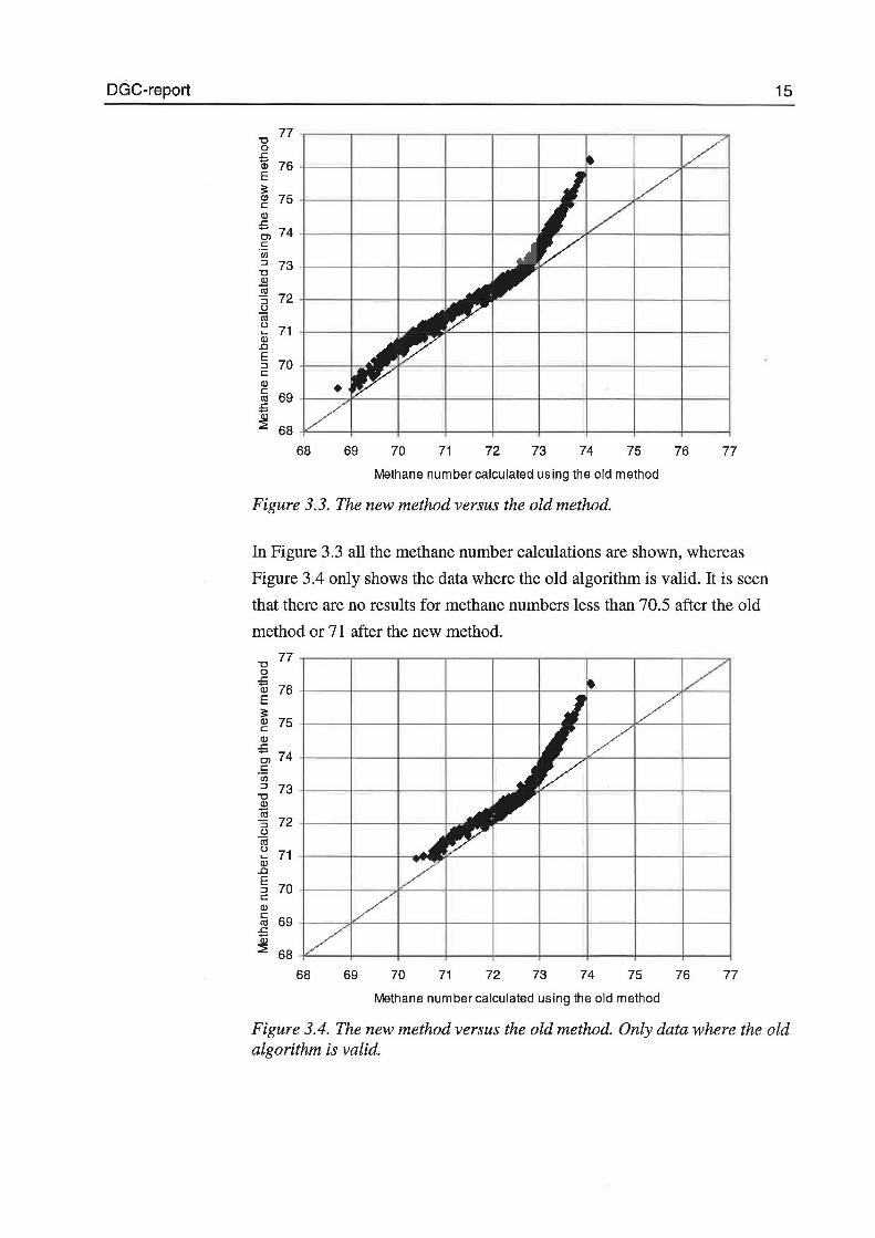
In Figure 3.3 the new DGC algorithm is compared with the old DGC algo
rithm u sin g the data for the Danish natura! gas quality from J anuary 1995 to
September 1998. There is very good agreement between the two algorithms
for gasses with a knocking resistance smaller than approximately 72.5.
DGC-report
u 77 .----.----.----.-----.----.----.----.----.--~ o 5 w 76 +----+----~--~----~----~---r----+---~~~ E s: ~ 75 +-----+------t------l-----t-----1--: w .c -;, 7 4 +----+----~--~----~------c c (J)
~ 73 +-----+------t------l-----+-~
~ :J 72 +----+-----t-----l~ u Cil u .... w .o
5 70 +-----+= c w c Cll .c
~ 68 *---~---+----r---~---+----~--~---+--~ 68 69 70 71 72 73 74 75 76 77
Melhane number calculaled using lhe old melhed
Figure 3.3. The new method versus the old method.
In Pigure 3.3 all the methane number calculations are shown, whereas
Pigure 3.4 only shows the data where the old algorithm is valid. It is seen
that there are no results for methane numbers less than 70.5 after the old
method or 71 after the new method.
u 77 o .c Qi 76 E s: w c w .c -;, 74 c (J) :J 73 u .æ Cll
72 :J u Cil u 71 .... w .o E
70 :J c w c
69 Cll .c
~ 68
68 69 70 71 72 73 74 75 76 77
Melhane number calculaled using lhe ol d melhed
15
Figure 3.4. The new method versus the old method. Only data where the old algorithm is valid.
DGC-report 16
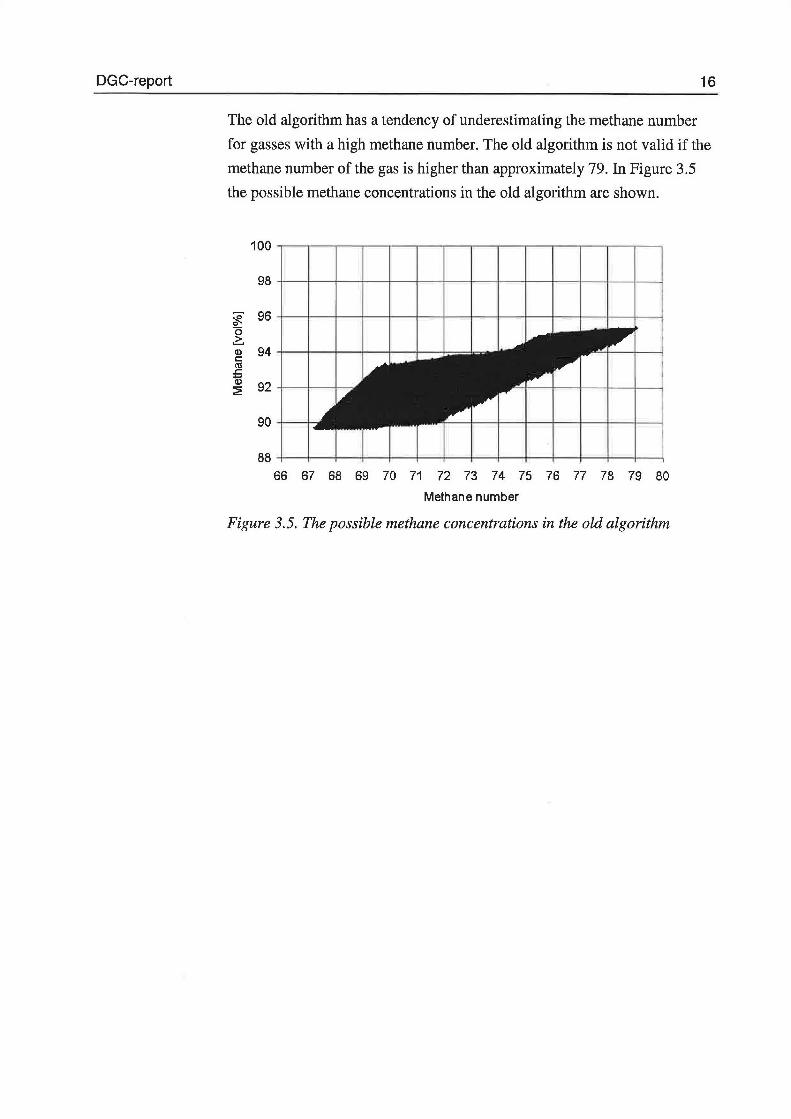
The ol d algorithm has a tenden c y of underestimating the methane number
for gasses with a high methane number. The old algorithm is not valid if the
methane number of the gas is higher than approximately 79. In Figure 3.5
the possible methane concentrations in the old algorithm are shown.
~ 96 +-~--,_~r--r--r--+--+-~--,_~r--r--+--+~ o 2:. :g 94 +----1---+---J----+---+---+=:::b ca
.J::. w ~ 92 +--+---!---:
66 67 68 69 70 71 72 73 74 75 76 77 78 79 80
Methane number
Figure 3.5. The possible methane concentrations in the old algorithm
DGC-report 17
4 Conclusions
The purpose of developing a new algorithm for determining the methane
number of natura! gasses has been fulfilled. The new algorithm is in good
agreement with the AVL /1/ data, the calculated results only vary
approximately ± l araund the AVL data.
There is good agreement between the old algorithm for gasses with methane
numbers lower than 72.5. The new algorithm gives results that are
approximately 0.5 higher than the old method.
Compared with other methods there is good agreement with some of the
methods. In general, however, there is a very large variation between the
methods.
The new algorithm has some limits given by the available data used as basis
for the algorithm. The calculations can only be made for gasses with a
methane number higher than 45 (without inert gasses). The concentration of
C02 eannot be higher than 30 vol%, and the concentration of N2 eannot be
higher than 50 vol%.
DGC-report 18
5 References
111 Forschungsberichte Verbrennungskraftmaschinen Heft 120, 1997,
'Erweiterung der Energieerzeugung durch Kraftgase, Teil3.
/2/ ASTM D-2699
/3/ ASTM D-2700
/4/ 'Engine knock rating ofnatural gases- Methane number', T .J.
Callahan, T.W. Ryan, S.R. King, 93-ICE-18, ASME,1993.
151 'Engine knock rating of natura! gases - expanding the roethane
number database', T.J Callahan et al., Jæ-vol27-4, ASME, 1996.
/6/ 'Application of the Waukesha Knock Index Methane number for
rating gaseous fuels', R.J. Selberg, Proceedings of the 22nd CIMAC
conference, 1998.
171 WKI program, Version 1.12, 1998.
/8/ 'Die Klopffestigkeit engineer Gase', P. Ferretti, Kraftstoff 1941.
191 Intemal Combustion Engine Fundamentals, J.B. Heywood, McGraw
Hill1988.
1101 Intemal GERG note 'Natura! Gas Quality on Gas Engines', 1998.
/11/ Draft ISOffC 193/SC N 129 (97-01-15)
DGC-report 19
6 Principle for calculating the methane number of
natural gasses
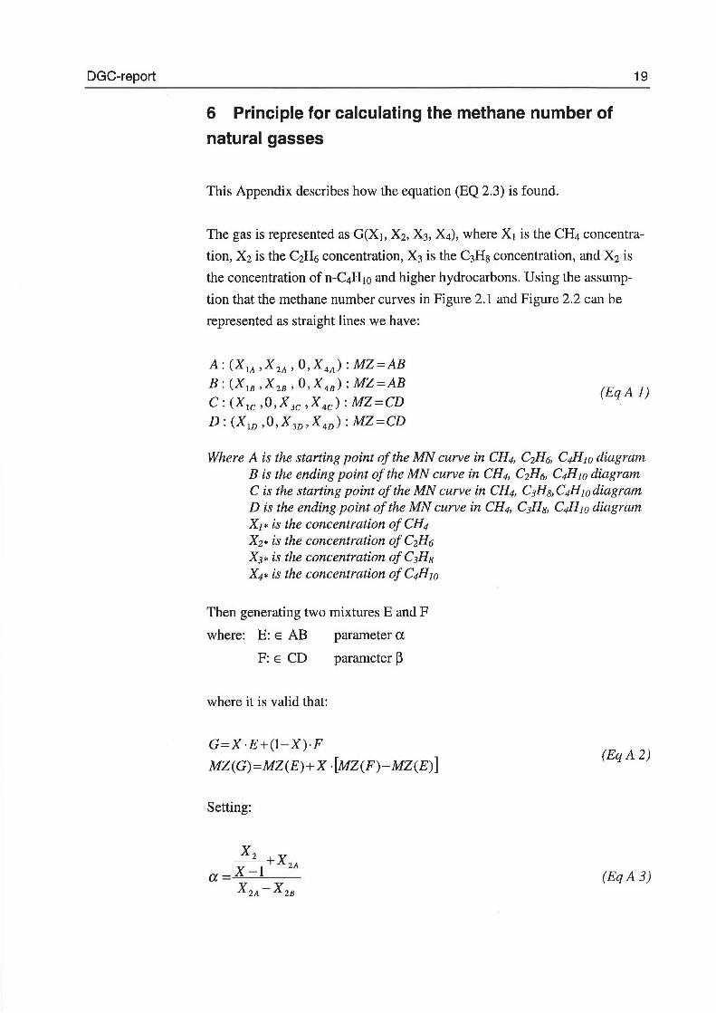
This Appendix describes how the equation (EQ 2.3) is found.
The gas is represented as G(X1, X2, X3, X4), where X1 is the CH4 concentra
tion, X2 is the C2H6 concentration, X3 is the C3Hs concentration, and X2 is
the concentration of n-C4H 10 and higher hydrocarbons. Using the assump
tion that the methane number curves in Pigure 2.1 and Pigure 2.2 can be
represented as straight lines we have:
A: (X1A ,X2A, o,X4A): MZ=AB
B: (XlB ,X2B' O,X4B): MZ=AB C: (X1c ,O,X3c ,X4c): MZ=CD
D: (Xw ,O,X3v,X4v): MZ=CD
(Eq A l)
Where A is the starting point ofthe MN curve in CH4, C2H6, C4H1o diagram B is the ending point ofthe MN curve in CH4, C2H6, C4Hw diagram C is the starting point ofthe MN curve in CH4, C3Hs,C4Hwdiagram D is the ending point ofthe MN curve in CH4, C3Hs, C4H10 diagram X1* is the concentration of CH4 X2* is the concentration of C2H6 X3* is the concentration of C3Hs X4* is the concentration of C4H1o
Then generating two mixtures E and F
where: E: E AB
F: E CD
where it is valid that:
parameter a
parameter Ø
G=X ·E+(l-X)·F
MZ(G)=MZ(E)+X ·[MZ(F)-MZ(E)]
Settin g:
a
x2 --+X2A X-1 X2A -X2B
(Eq A 2)
(Eq A 3)
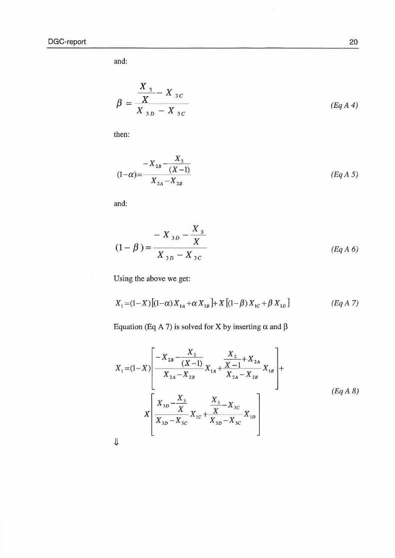
DGC-report
and:
x 3 - x X 3C f3 = --==---
x 3D -x 3C
then:
-x - x2 28
(1-a)= (X-1) X 2A -Xza
and:
x 3 -X - -3D
(1-/3)= x X 30- X 3C
U sing tb e a bove w e get:
Equation (Eq A 7) is solved for X by inserting a and ~
x - x3 x3 Jn X X-X3c
X ---XJc+ Xw X 3D -X3C X 3D -X3C
20
(Eq A 4)
(EqA 5)
(EqA 6)
(Eq A 7)
(Eq A 8)
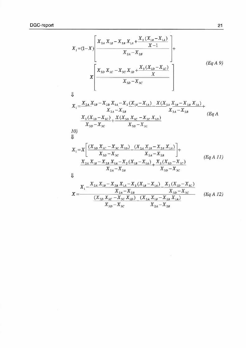
DGC-report
JO) ~
X X -X X X3 (Xw -Xtc) 3D IC 3C ID+ x
x -------------------------x3D -x3c
+
XI =X [(X3D xlC -X3C Xw) (X2A XIB -X2B xlA)]+ x 3D -x3c x~M -x2s
x 2A x IB -x2n x lA -x2 cx1s -x lA)+ x3 (XI D -X !C )
X 2A -x 2 8 X 3D -X 3C
x
X 3D -X3c
21
(Eq A 9)
(EqA
(EqA 11)
(EqA 12)
DGC-report 22
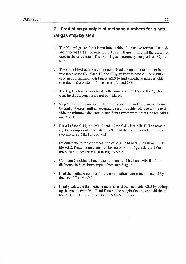
7 Prediction principle of methane numbers for a natu
ral gas step by step
l. The Natural gas analysis is put into a table of the above format. The H2S and odorant (THT) are only present in small quantities, and therefore not used in the calculation. The Danish gas is normall y analysedas a C6+ result.
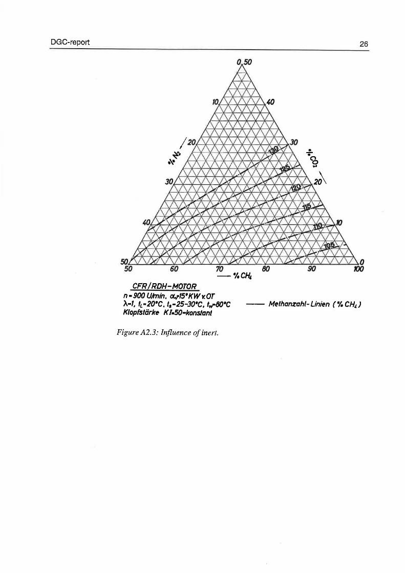
2. The sum of hydrocarbon components is added up and the number is out into table at the C1+ place. N2 and C02 are kept as before. The result is used in cernbination with Pigure A2.3 to findamethane number addition due to the content of inert gases (N2 and C02).
3. The C4+ fraction is calculated as the sum o f all C4, C5 and the C6+ fraction. Inert components are not considered.
4. Step 5 to 7 is the most difficult steps to perform, and they are performed bytrialand error, until an acceptable result is achieved. The aim is to divide the mixture calculated in step 3 into two new mixtures, called Mix I andMix II.
5. Put all of the C2H6 into Mix I, and all the C3H8 into Mix II. The remaining two components from step 3, CH4 and the C4+ are divided into the two mixtures, Mix I and Mix II
6. Calculate the relative composition of Mix I and Mix II, as shown in T able A2.2. Read the methane number for Mix I in Pigure 2.1, and the methane number for Mix II in Pigure A2.2.
7. Compare the obtained methane numbers for Mix I and Mix Il. If the difference is 5 or above, repeat from step 5 again.
8. Find the methane number for the composition determined in step 2 by the use of Pigure A2.3.
9. Finally calculate the methane number as shown in Table A2.3 by adding up the results from Mix I and II using the weight factors, and add the effect of inert. The result is 70.7 in methane number.
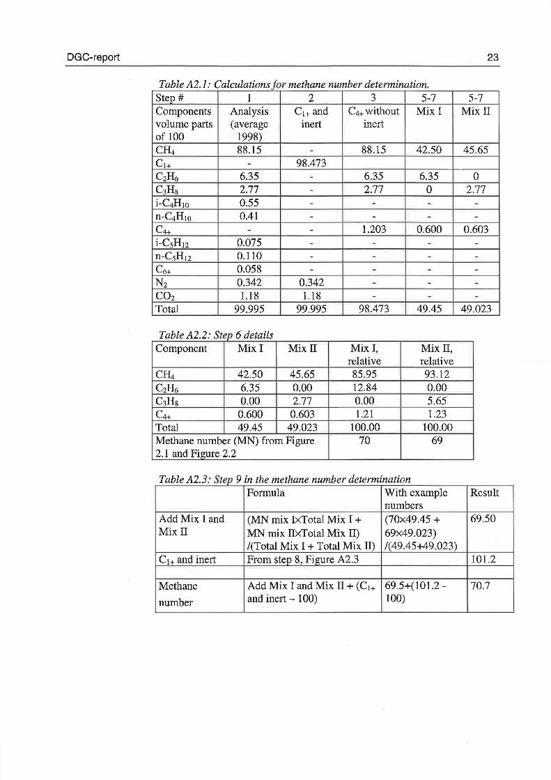
DGC-report 23
Table A2.1: Calculations formethane number determination. Step # l 2 3 5-7 5-7 Components Analys is cl+ and c4+ without Mixi Mixll volume parts ( average inert inert of 100 1998) CH4 88.15 - 88.15 42.50 45.65 c l+ - 98.473 CzH6 6.35 - 6.35 6.35 o C3Hs 2.77 - 2.77 o 2.77 i-C4H10 0.55 - - - -n-C4H10 0.41 - - - -c4+ - - 1.203 0.600 0.603 i-CsH12 0.075 - - - -n-CsH12 0.110 - - - -c6+ 0.058 - - - -N z 0.342 0.342 - - -CO z 1.18 1.18 - - -Total 99.995 99.995 98.473 49.45 49.023
r, bl A2 2 s 6 d ·z a e te p etm s Component Mixi Mixll Mixi, Mix II,
relative relative CH4 42.50 45.65 85.95 93.12 CzH6 6.35 0.00 12.84 0.00 C3Hs 0.00 2.77 0.00 5.65 c4+ 0.600 0.603 1.21 1.23 Total 49.45 49.023 100.00 100.00 Methane number (MN) from Pigure 70 69 2.1 and Pigure 2.2
T, bl A2 3 S 9 . h b d h a e te p m t e met ane num er etermmatwn Formul a With example Result
numbers AddMixiand (MN mix IxTotal Mix I+ (70x49.45 + 69.50 Mixll MN mix lixTotal Mix IT) 69x49.023)
/(Total Mix I + Total Mix Il) /( 49 .45+49 .023) cl+ and inert From step 8, Pigure A2.3 101.2
Methane Add Mix I and Mix II+ (C1+ 69.5+(101.2- 70.7
number and inert - 100) 100)
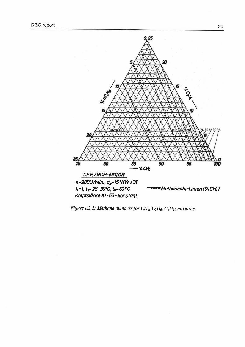
DGC-report 24
• • \ ~~-4X-*---*+*-~~It-\-?. 10\
CFR/RDH-MOTDR n·900U/min .. ~v·15°KWv.OT A •1, ts•25-30°C, tw-80°C Klopfstarke K/• 50· konstant
--Methanzahi-Linien (%C~)
Figur e A2.1: M et hane numbers for CH4, C2H6, C4H10 mixtures.
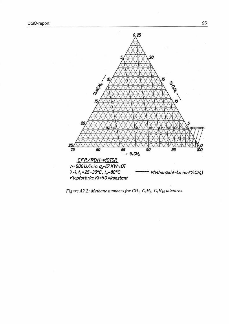
DGC-report 25
CFR/RDH-MOTOR n=9DDU/min. rtv·15•Kwv.or }...1, ts•25-3o•c, fw•BO•c K/opfstarke K/·50 •konstant
------- Methanzahi-Linien(%C~J
Pigure A2.2: Methane numbers for CH4, C3Hs, C4H10 mixtures.
DG C-re port
CFR /RDH-MOTOR n· 900 UAnin, f:X./'15' KW v. OT A•1, IL•20'C,I5 •25-30'C, lw-BO'C Klopfslark~ K /.SO-konstant
Figure A2.3: lnfluence of inert.
26
• • CO ...
-- M~lhanzah/- Lini~n (% CH,)