Embed Size (px)
Citation preview
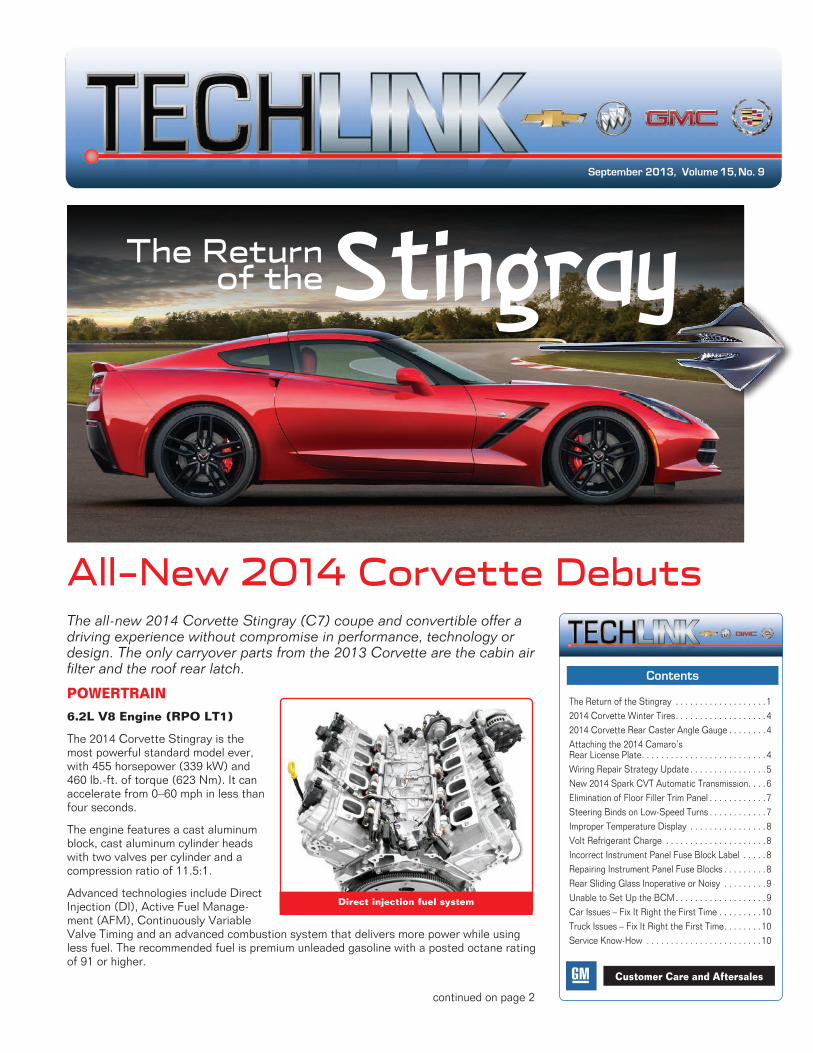
September 2013, Volume 15, No. 9
Contents
The Return of the Stingray . . . . . . . . . . . . . . . . . . . 12014 Corvette Winter Tires . . . . . . . . . . . . . . . . . . . 42014 Corvette Rear Caster Angle Gauge . . . . . . . . 4Attaching the 2014 Camaro’s Rear License Plate . . . . . . . . . . . . . . . . . . . . . . . . . . 4Wiring Repair Strategy Update . . . . . . . . . . . . . . . . 5New 2014 Spark CVT Automatic Transmission . . . .6Elimination of Floor Filler Trim Panel . . . . . . . . . . . . 7Steering Binds on Low-Speed Turns . . . . . . . . . . . . 7Improper Temperature Display . . . . . . . . . . . . . . . . 8Volt Refrigerant Charge . . . . . . . . . . . . . . . . . . . . . 8Incorrect Instrument Panel Fuse Block Label . . . . . 8Repairing Instrument Panel Fuse Blocks . . . . . . . . . 8Rear Sliding Glass Inoperative or Noisy . . . . . . . . . 9Unable to Set Up the BCM . . . . . . . . . . . . . . . . . . . 9Car Issues – Fix It Right the First Time . . . . . . . . . 10Truck Issues – Fix It Right the First Time . . . . . . . . 10Service Know-How . . . . . . . . . . . . . . . . . . . . . . . . 10
Customer Care and Aftersales
continued on page 2
The all-new 2014 Corvette Stingray (C7) coupe and convertible offer a driving experience without compromise in performance, technology or design. The only carryover parts from the 2013 Corvette are the cabin air filter and the roof rear latch.
POWERTRAIN
6.2L V8 Engine (RPO LT1)
The 2014 Corvette Stingray is the most powerful standard model ever, with 455 horsepower (339 kW) and 460 lb .-ft . of torque (623 Nm) . It can accelerate from 0–60 mph in less than four seconds .
The engine features a cast aluminum block, cast aluminum cylinder heads with two valves per cylinder and a compression ratio of 11 .5:1 .
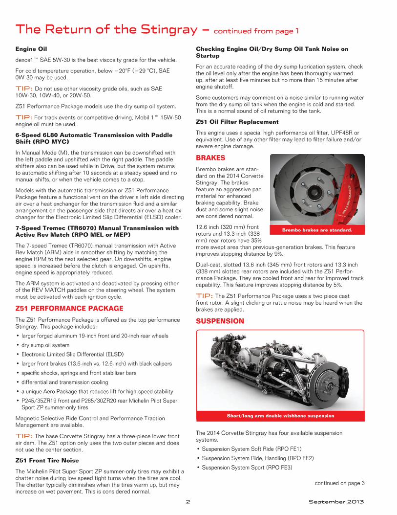
Advanced technologies include Direct Injection (DI), Active Fuel Manage-ment (AFM), Continuously Variable Valve Timing and an advanced combustion system that delivers more power while using less fuel . The recommended fuel is premium unleaded gasoline with a posted octane rating of 91 or higher .
The Return of the
All-New 2014 Corvette Debuts
Direct injection fuel system
2 September 2013
The Return of the Stingray – continued from page 1
Engine Oil
dexos1™ SAE 5W-30 is the best viscosity grade for the vehicle .
For cold temperature operation, below −20°F (−29 °C), SAE 0W-30 may be used .
TIP: Do not use other viscosity grade oils, such as SAE 10W-30, 10W-40, or 20W-50 .
Z51 Performance Package models use the dry sump oil system .
TIP: For track events or competitive driving, Mobil 1™ 15W-50 engine oil must be used .
6-Speed 6L80 Automatic Transmission with Paddle Shift (RPO MYC)
In Manual Mode (M), the transmission can be downshifted with the left paddle and upshifted with the right paddle . The paddle shifters also can be used while in Drive, but the system returns to automatic shifting after 10 seconds at a steady speed and no manual shifts, or when the vehicle comes to a stop .
Models with the automatic transmission or Z51 Performance Package feature a functional vent on the driver’s left side directing air over a heat exchanger for the transmission fluid and a similar arrangement on the passenger side that directs air over a heat ex-changer for the Electronic Limited Slip Differential (ELSD) cooler .
7-Speed Tremec (TR6070) Manual Transmission with Active Rev Match (RPO MEL or MEP)
The 7-speed Tremec (TR6070) manual transmission with Active Rev Match (ARM) aids in smoother shifting by matching the engine RPM to the next selected gear . On downshifts, engine speed is increased before the clutch is engaged . On upshifts, engine speed is appropriately reduced .
The ARM system is activated and deactivated by pressing either of the REV MATCH paddles on the steering wheel . The system must be activated with each ignition cycle .
Z51 PERFORMANCE PACKAGE
The Z51 Performance Package is offered as the top performance Stingray . This package includes:
• largerforgedaluminum19-inchfrontand20-inchrearwheels
•drysumpoilsystem
•ElectronicLimitedSlipDifferential(ELSD)
• largerfrontbrakes(13.6-inchvs.12.6-inch)withblackcalipers
•specificshocks,springsandfrontstabilizerbars
•differentialandtransmissioncooling
•auniqueAeroPackagethatreducesliftforhigh-speedstability
•P245/35ZR19frontandP285/30ZR20rearMichelinPilotSuperSport ZP summer-only tires
Magnetic Selective Ride Control and Performance Traction Management are available .
TIP: The base Corvette Stingray has a three-piece lower front air dam . The Z51 option only uses the two outer pieces and does not use the center section .
Z51 Front Tire Noise
The Michelin Pilot Super Sport ZP summer-only tires may exhibit a chatter noise during low speed tight turns when the tires are cool . The chatter typically diminishes when the tires warm up, but may increase on wet pavement . This is considered normal .
Checking Engine Oil/Dry Sump Oil Tank Noise on Startup
For an accurate reading of the dry sump lubrication system, check the oil level only after the engine has been thoroughly warmed up,afteratleastfiveminutesbutnomorethan15minutesafterengine shutoff .
Some customers may comment on a noise similar to running water from the dry sump oil tank when the engine is cold and started . This is a normal sound of oil returning to the tank .
Z51 Oil Filter Replacement
Thisengineusesaspecialhighperformanceoilfilter,UPF48Rorequivalent.Useofanyotherfiltermayleadtofilterfailureand/orsevere engine damage .
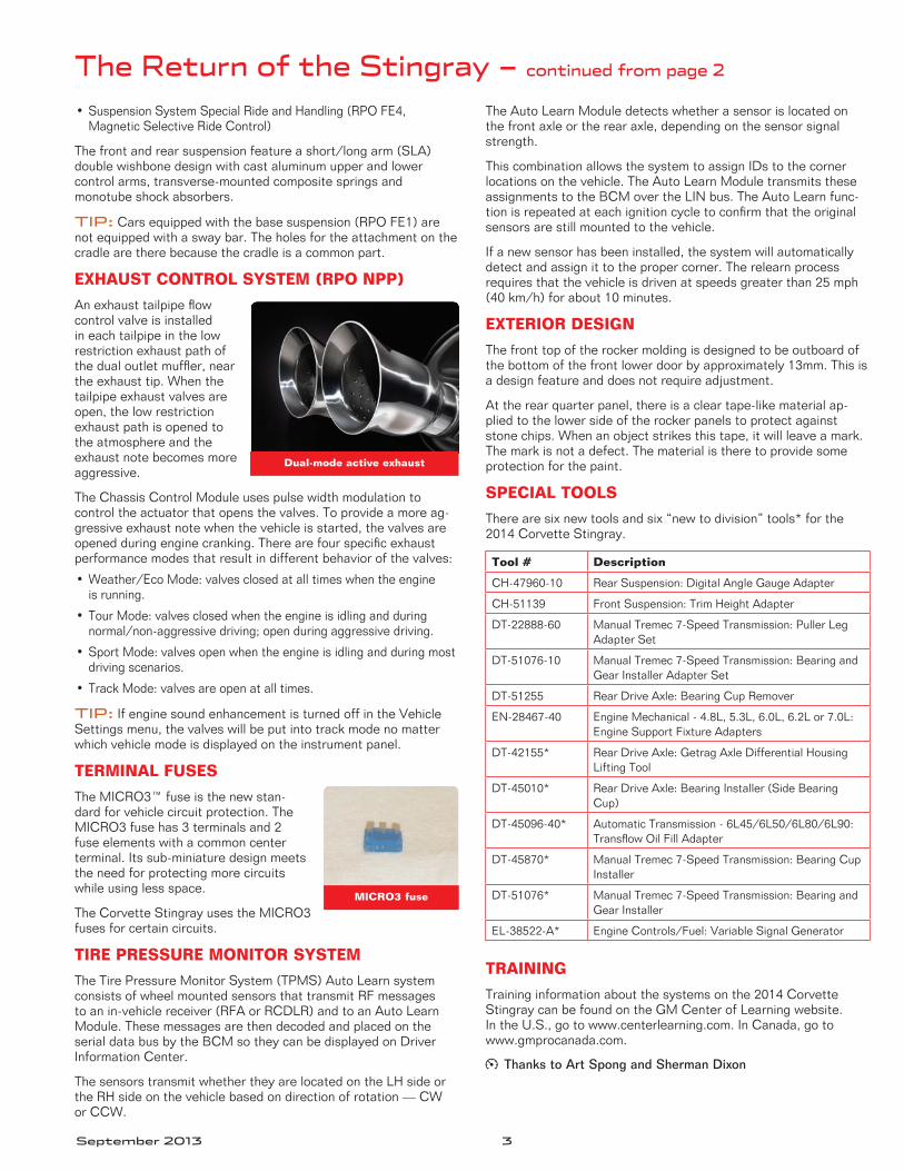
BRAKES
Brembo brakes are stan-dard on the 2014 Corvette Stingray . The brakes feature an aggressive pad material for enhanced braking capability . Brake dust and some slight noise are considered normal .
12 .6 inch (320 mm) front rotors and 13 .3 inch (338 mm) rear rotors have 35% more swept area than previous-generation brakes . This feature improves stopping distance by 9% .
Dual-cast, slotted 13 .6 inch (345 mm) front rotors and 13 .3 inch (338 mm) slotted rear rotors are included with the Z51 Perfor-mance Package . They are cooled front and rear for improved track capability . This feature improves stopping distance by 5% .
TIP: The Z51 Performance Package uses a two piece cast front rotor . A slight clicking or rattle noise may be heard when the brakes are applied .
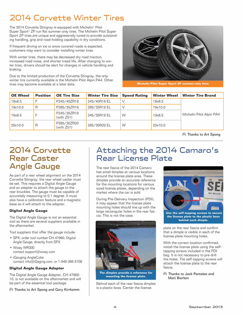
SUSPENSION
The 2014 Corvette Stingray has four available suspension systems .
•SuspensionSystemSoftRide(RPOFE1)
•SuspensionSystemRide,Handling(RPOFE2)
•SuspensionSystemSport(RPOFE3)
continued on page 3
Brembo brakes are standard.
Short/long arm double wishbone suspension
September 2013 3
The Return of the Stingray – continued from page 2
•SuspensionSystemSpecialRideandHandling(RPOFE4, Magnetic Selective Ride Control)
Thefrontandrearsuspensionfeatureashort/longarm(SLA)double wishbone design with cast aluminum upper and lower control arms, transverse-mounted composite springs and monotube shock absorbers .
TIP: Cars equipped with the base suspension (RPO FE1) are not equipped with a sway bar . The holes for the attachment on the cradle are there because the cradle is a common part .
EXHAUST CONTROL SYSTEM (RPO NPP)
An exhaust tailpipe flow control valve is installed in each tailpipe in the low restriction exhaust path of the dual outlet muffler, near the exhaust tip . When the tailpipe exhaust valves are open, the low restriction exhaust path is opened to the atmosphere and the exhaust note becomes more aggressive .
The Chassis Control Module uses pulse width modulation to control the actuator that opens the valves . To provide a more ag-gressive exhaust note when the vehicle is started, the valves are openedduringenginecranking.Therearefourspecificexhaustperformance modes that result in different behavior of the valves:
•Weather/EcoMode:valvesclosedatalltimeswhentheengineis running .
•TourMode:valvesclosedwhentheengineisidlingandduringnormal/non-aggressivedriving;openduringaggressivedriving.
•SportMode:valvesopenwhentheengineisidlingandduringmostdriving scenarios .
•TrackMode:valvesareopenatalltimes.
TIP: If engine sound enhancement is turned off in the Vehicle Settings menu, the valves will be put into track mode no matter which vehicle mode is displayed on the instrument panel .
TERMINAL FUSES
The MICRO3™ fuse is the new stan-dard for vehicle circuit protection . The MICRO3 fuse has 3 terminals and 2 fuse elements with a common center terminal . Its sub-miniature design meets the need for protecting more circuits while using less space .
The Corvette Stingray uses the MICRO3 fuses for certain circuits .
TIRE PRESSURE MONITOR SYSTEM
The Tire Pressure Monitor System (TPMS) Auto Learn system consists of wheel mounted sensors that transmit RF messages to an in-vehicle receiver (RFA or RCDLR) and to an Auto Learn Module . These messages are then decoded and placed on the serial data bus by the BCM so they can be displayed on Driver Information Center .
The sensors transmit whether they are located on the LH side or the RH side on the vehicle based on direction of rotation — CW or CCW .
The Auto Learn Module detects whether a sensor is located on the front axle or the rear axle, depending on the sensor signal strength .
This combination allows the system to assign IDs to the corner locations on the vehicle . The Auto Learn Module transmits these assignments to the BCM over the LIN bus . The Auto Learn func-tionisrepeatedateachignitioncycletoconfirmthattheoriginalsensors are still mounted to the vehicle .
If a new sensor has been installed, the system will automatically detect and assign it to the proper corner . The relearn process requires that the vehicle is driven at speeds greater than 25 mph (40km/h)forabout10minutes.
EXTERIOR DESIGN
The front top of the rocker molding is designed to be outboard of the bottom of the front lower door by approximately 13mm . This is a design feature and does not require adjustment .
At the rear quarter panel, there is a clear tape-like material ap-plied to the lower side of the rocker panels to protect against stone chips . When an object strikes this tape, it will leave a mark . The mark is not a defect . The material is there to provide some protection for the paint .
SPECIAL TOOLS
There are six new tools and six “new to division” tools* for the 2014 Corvette Stingray .
TRAINING
Training information about the systems on the 2014 Corvette Stingray can be found on the GM Center of Learning website . In the U .S ., go to www .centerlearning .com . In Canada, go to www .gmprocanada .com .
Thanks to Art Spong and Sherman Dixon
Dual-mode active exhaust
MICRO3 fuse
Tool # Description
CH-47960-10 Rear Suspension: Digital Angle Gauge Adapter
CH-51139 Front Suspension: Trim Height Adapter
DT-22888-60 Manual Tremec 7-Speed Transmission: Puller Leg Adapter Set
DT-51076-10 Manual Tremec 7-Speed Transmission: Bearing and Gear Installer Adapter Set
DT-51255 Rear Drive Axle: Bearing Cup Remover
EN-28467-40 Engine Mechanical - 4 .8L, 5 .3L, 6 .0L, 6 .2L or 7 .0L: Engine Support Fixture Adapters
DT-42155* Rear Drive Axle: Getrag Axle Differential Housing Lifting Tool
DT-45010* Rear Drive Axle: Bearing Installer (Side Bearing Cup)
DT-45096-40* AutomaticTransmission-6L45/6L50/6L80/6L90:Transflow Oil Fill Adapter
DT-45870* Manual Tremec 7-Speed Transmission: Bearing Cup Installer
DT-51076* Manual Tremec 7-Speed Transmission: Bearing and Gear Installer
EL-38522-A* EngineControls/Fuel:VariableSignalGenerator
4 September 2013
The 2014 Corvette Stingray is equipped with Michelin® Pilot Super Sport® ZP run-flat summer-only tires . The Michelin Pilot Super Sport ZP tires are unique and aggressively tuned to provide outstand-ing handling, grip and road-holding capability in dry conditions .
If frequent driving on ice or snow covered roads is expected, customers may want to consider installing winter tires .
With winter tires, there may be decreased dry road traction, increased road noise, and shorter tread life . After changing to win-ter tires, drivers should be alert for changes in vehicle handling and braking .
Due to the limited production of the Corvette Stingray, the only winter tire currently available is the Michelin Pilot Alpin PA4 . Other tires may become available at a later date .
2014 Corvette Winter Tires
2014 Corvette Rear Caster Angle GaugeAs part of a rear wheel alignment on the 2014 Corvette Stingray, the rear wheel caster must be set . This requires a Digital Angle Gauge and an adapter to attach the gauge to the rear knuckles . The gauge must be capable of accurately measuring to 0 .1 degree . It must also have a calibration feature and a magnetic base so it will attach to the adapter .
Digital Angle Gauge
The Digital Angle Gauge is not an essential tool as there are several suppliers available in the aftermarket .
Tool suppliers that offer the gauge include:
•SPX;ordertoolnumberCH-47960,DigitalAngleGauge,directlyfromSPX
•WixeyWR300 contact support@wixey .com
• iGaugingAngleCube contact info@iGaging .com, or 1-949-366-5708
Digital Angle Gauge Adapter
The Digital Angle Gauge Adapter, CH-47960-10, is not available on the aftermarket and will be part of the essential tool package .
Thanks to Art Spong and Gary Kirrkamm
OE Wheel Position OE Tire Size Winter Tire Size Speed Rating Winter Wheel Winter Tire Brand
18x8 .5 F P245/40ZR18 245/40R18EL V 18x8 .5
Michelin Pilot Alpin PA4
19x10 .0 R P285/35ZR19 285/35R19EL V 19x10 .0
19x8 .5 F P245/35ZR19(with Z51) 245/35R19EL W 19x8 .5
20x10 .0 R P285/30ZR20(with Z51) 285/30R20EL W 20x10 .0
Michelin Pilot Super Sport ZP summer-only tires
Attaching the 2014 Camaro’s Rear License PlateThe rear fascia of the 2014 Camaro has small dimples at various locations around the license plate area . These dimples provide an accurate reference for the mounting locations for various sizedlicenseplates,dependingonthemarket where the car is sold .
During Pre-Delivery Inspection (PDI), it may appear that the license plate mounting holes should line up with the large rectangular holes in the rear fas-cia . This is not the case .
Behind each of the rear fascia dimples is a plastic boss . Center the license
plateontherearfasciaandconfirmthat a dimple is visible in each of the license plate mounting holes .
Withthecorrectlocationconfirmed,install the license plate using the self-tapping screws included in the PDI bag . It is not necessary to pre-drill the holes . The self-tapping screws will attach the license plate to the rear fascia .
Thanks to Jack Pantaleo and Matt Bierlein
The dimples provide a reference for mounting the license plate.
Use the self-tapping screws to secure the license plate to the plastic boss
behind each dimple.
Thanks to Art Spong
September 2013 5
Wiring Repair Strategy Update and Parts InformationGM’s global wiring repair strategy is to repair major harnesses (body, engine, instrument panel, forward lamp, etc .) whenever possible and to service minor harnesses (door, seat, steering column, etc .) as assemblies .
This direction was established to reduce the number of individual part numbers needed to service GM vehicles, as even small har-nesses can have many different part numbers for the individual connectors and terminals . When new terminals or connectors are released within the major harnesses, they are serviced through the release of connectors, terminated leads, pigtails, etc . and made available through GM Customer Care and Aftersales . If a terminal happens to be a legacy part already available in the J-38125 Terminal Repair Kit, it will be called out in the Service Information .
Terminal Repair Kit
There are two sources for wire harness repair parts: the J-38125 Terminal Repair Kit and the dealership parts department .
The J-38125 Terminal Repair Kit is still a very valuable resource . Many of the terminals that are available in the kit still are in use on current model vehicles . The kit also contains many tools and instructions to service harness connectors and wiring .
TIP: Replenishment tools and terminals for the J-38125 kit are availablethroughSPXat1-800-468-6657.
To download an electronic copy of the J-38125 Terminal Repair Kit Instruction Manual, go to the GM Center of Learning website at www .centerlearning .com . Click Resources > STC Training Materials > Service Technical Books . (In Canada, go to Library > Service > Technician Resources in GM GlobalConnect .)
Parts Information
The Connector End View section of the Service Information is the source for part number information and where to obtain parts . The part information is found just below the connector end view drawing and is presented two ways — the legacy format typi-cally associated with TIFF viewer-supported graphics and the new format typically associated with the new CGM viewer-supported graphics .
Thisinformationshowstwodifferentpartnumbers;oneisonlyavailable as a terminated lead and the other is available both as a terminated lead and in the terminal repair kit . The information
in the Service Terminal column lists the part number for terminals that were released in the J-38125 Terminal Repair Kit, followed by the Tray Number and Crimping Information .
TXL Wire
TXLwireshouldbeusedtomaintainfactoryspecificationsforwireharnessintegrity.TXLwireisavailablethroughtheCustomerCare and Aftersales parts catalog within the Chemical Catalog section .
TIP:FindTXLwireandfusesintheChemicals–Fuses–Wire– book section . To locate this section in the EPC, select Make, Year, and Model, and then select Chemicals – Fuses – Wire catalog.TXLWirewillbecalledoutundergroup8.966Wire, Primary wire . Fuses are located under group 8 .965 Fuse .
Repair Procedures
With the repair strategy of repairing instead of replacing large harnesses in the vehicle, it’s important to have the ability to perform wire-to-wire repair, connector repair, and terminal replacement .
Extensive repair procedures are covered in the Service Informa-tion . Go to Power and Signal Distribution > Wiring Systems and Power Management > Diagnostic Information and Procedures . The information covers wiring and terminal replacement proce-dures as well as disassembly instructions for various connectors . A listing of required materials to correctly perform wiring repairs also is provided, including splice sleeves and heat shrinking tubing .
Additional Reference
Another useful reference for wiring and terminal repairs is the Terminal Repair Kit Update available on the TechLink website . ThislargefilepresentseverystepinthehistoryoftheJ-38125TerminalRepairKitalongwithhowtoorganizethekitwithall updates .
Thanks to Rob Prough
J-38125 Terminal Repair Kit
New format with CGM viewer-supported graphics
6 September 2013
New 2014 Spark CVT Automatic TransmissionThe 2014 Spark features an available Continuous Variable Trans-mission (CVT) automatic transmission (RPO M4M) . The CVT transmission, manufactured by JATCO, operates with a pair of variable pulleys, a steel belt and a shifting ratio planetary gear set .
TIP: The CVT transmission is currently on a parts restriction through the Product Quality Center . The unit should be replaced as an assembly if repairs are needed .
CVT Operation
Although a vehicle’s engine can make power over a wide range of RPMandtorquecombinations,itismostefficientatcertainpointson the power curve . The transmission is used to select which part oftheengine’spowercurveisused.Fueleconomyisoptimizedwhen the required power level is matched with the minimum fuel consumption point .
If the transmission had a single ratio, the vehicle’s speed would be a linear function of the engine’s speed . However, in this in-stance, the vehicle’s maximum speed would correspond with the engine’s maximum speed . Plus, because internal combustion engines usually deliver very low torque at low speeds, the power available at low speed would be very low, resulting in poor ve-hicle acceleration .
To overcome these issues, the typical vehicle transmission has a numberoffixed-ratiogearselections.Thesearecalledstep-ratiotransmissions . There are some compromises in using a step-ratio transmission . For instance, power is momentarily removed from the drive wheels while the shift occurs . When the shift to the next higher gear is completed, the engine RPM is reduced, with a resulting reduction in applied power .
A CVT is step-less, so it allows smooth ratio changes without power interruption and enables the engine to remain at its maxi-mum power RPM . The CVT’s continuous application of maximum power can result in improved vehicle acceleration .
Since the CVT can operate at any engine RPM within the limits ofitsratiorange,itoffersimprovedefficiency.Notransmissionis100%efficient;someinputpowerisconsumedbythetransmis-sion . For the CVT, although the power consumed may be higher than a conventional step-ratio transmission, this can be offset by constantlyrunningtheengineatitsoptimizedoperatingpoint.
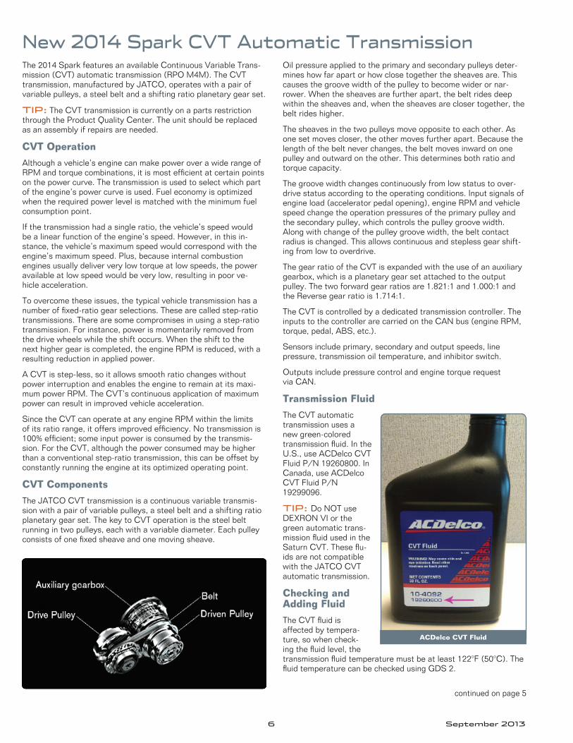
CVT Components
The JATCO CVT transmission is a continuous variable transmis-sion with a pair of variable pulleys, a steel belt and a shifting ratio planetary gear set . The key to CVT operation is the steel belt running in two pulleys, each with a variable diameter . Each pulley consistsofonefixedsheaveandonemovingsheave.
Oil pressure applied to the primary and secondary pulleys deter-mines how far apart or how close together the sheaves are . This causes the groove width of the pulley to become wider or nar-rower . When the sheaves are further apart, the belt rides deep within the sheaves and, when the sheaves are closer together, the belt rides higher .
The sheaves in the two pulleys move opposite to each other . As one set moves closer, the other moves further apart . Because the length of the belt never changes, the belt moves inward on one pulley and outward on the other . This determines both ratio and torque capacity .
The groove width changes continuously from low status to over-drive status according to the operating conditions . Input signals of engine load (accelerator pedal opening), engine RPM and vehicle speed change the operation pressures of the primary pulley and the secondary pulley, which controls the pulley groove width . Along with change of the pulley groove width, the belt contact radius is changed . This allows continuous and stepless gear shift-ing from low to overdrive .
The gear ratio of the CVT is expanded with the use of an auxiliary gearbox, which is a planetary gear set attached to the output pulley . The two forward gear ratios are 1 .821:1 and 1 .000:1 and the Reverse gear ratio is 1 .714:1 .
The CVT is controlled by a dedicated transmission controller . The inputs to the controller are carried on the CAN bus (engine RPM, torque, pedal, ABS, etc .) .
Sensors include primary, secondary and output speeds, line pressure, transmission oil temperature, and inhibitor switch .
Outputs include pressure control and engine torque request via CAN .
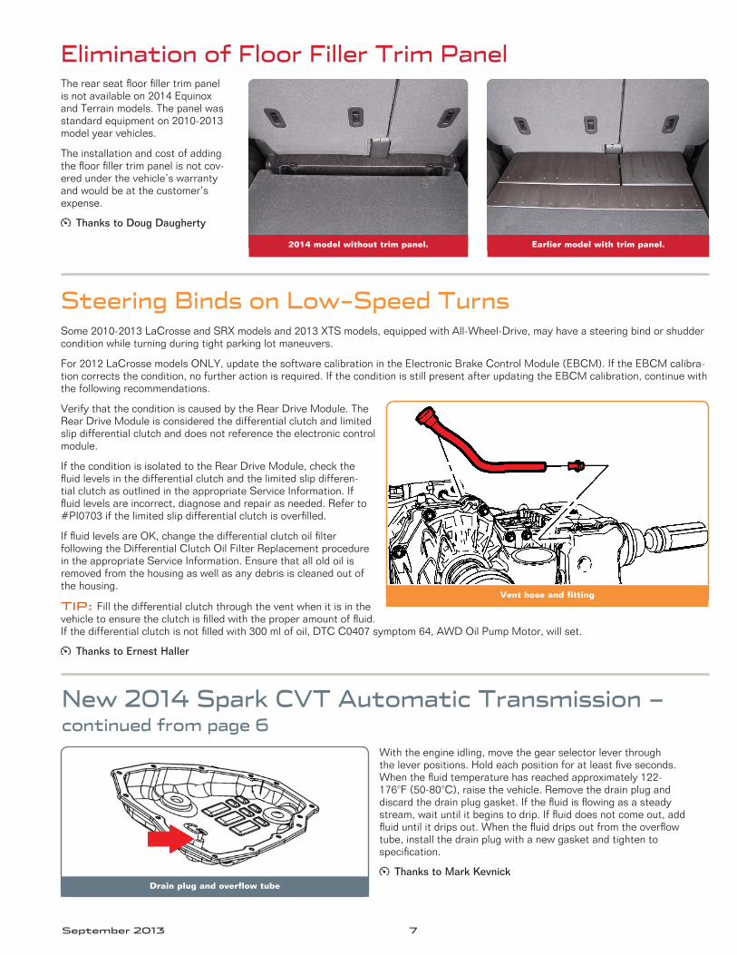
Transmission Fluid
The CVT automatic transmission uses a new green-colored transmission fluid . In the U .S ., use ACDelco CVT FluidP/N19260800.In Canada, use ACDelco CVTFluidP/N19299096 .
TIP: Do NOT use DEXRONVIorthegreen automatic trans-mission fluid used in the Saturn CVT . These flu-ids are not compatible with the JATCO CVT automatic transmission .
Checking and Adding Fluid
The CVT fluid is affected by tempera-ture, so when check-ing the fluid level, the transmission fluid temperature must be at least 122°F (50°C) . The fluid temperature can be checked using GDS 2 .
ACDelco CVT Fluid
continued on page 5
September 2013 7
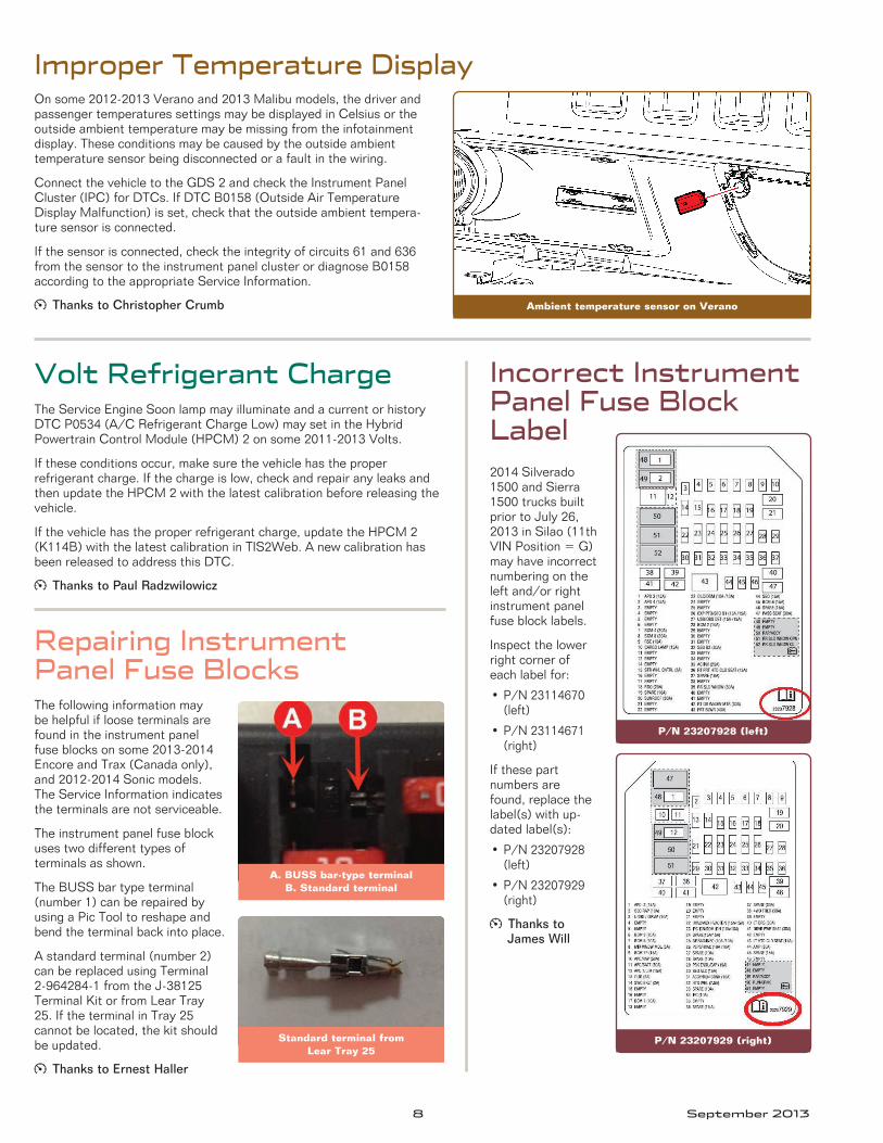
New 2014 Spark CVT Automatic Transmission – continued from page 6
With the engine idling, move the gear selector lever through theleverpositions.Holdeachpositionforatleastfiveseconds.When the fluid temperature has reached approximately 122-176°F (50-80°C), raise the vehicle . Remove the drain plug and discard the drain plug gasket . If the fluid is flowing as a steady stream, wait until it begins to drip . If fluid does not come out, add fluid until it drips out . When the fluid drips out from the overflow tube, install the drain plug with a new gasket and tighten to specification.
Thanks to Mark KevnickDrain plug and overflow tube
Elimination of Floor Filler Trim PanelTherearseatfloorfillertrimpanelis not available on 2014 Equinox and Terrain models . The panel was standard equipment on 2010-2013 model year vehicles .
The installation and cost of adding thefloorfillertrimpanelisnotcov-ered under the vehicle’s warranty and would be at the customer’s expense .
Thanks to Doug Daugherty
2014 model without trim panel. Earlier model with trim panel.
Some2010-2013LaCrosseandSRXmodelsand2013XTSmodels,equippedwithAll-Wheel-Drive,mayhaveasteeringbindorshuddercondition while turning during tight parking lot maneuvers .
For 2012 LaCrosse models ONLY, update the software calibration in the Electronic Brake Control Module (EBCM) . If the EBCM calibra-tion corrects the condition, no further action is required . If the condition is still present after updating the EBCM calibration, continue with the following recommendations .
Verify that the condition is caused by the Rear Drive Module . The Rear Drive Module is considered the differential clutch and limited slip differential clutch and does not reference the electronic control module .
If the condition is isolated to the Rear Drive Module, check the fluid levels in the differential clutch and the limited slip differen-tial clutch as outlined in the appropriate Service Information . If fluid levels are incorrect, diagnose and repair as needed . Refer to #PI0703ifthelimitedslipdifferentialclutchisoverfilled.
IffluidlevelsareOK,changethedifferentialclutchoilfilter following the Differential Clutch Oil Filter Replacement procedure in the appropriate Service Information . Ensure that all old oil is removed from the housing as well as any debris is cleaned out of the housing .
TIP: Fill the differential clutch through the vent when it is in the vehicletoensuretheclutchisfilledwiththeproperamountoffluid.Ifthedifferentialclutchisnotfilledwith300mlofoil,DTCC0407symptom64,AWDOilPumpMotor,willset.
Thanks to Ernest Haller
Vent hose and fitting
Steering Binds on Low-Speed Turns
8 September 2013
Incorrect Instrument Panel Fuse Block Label2014 Silverado 1500 and Sierra 1500 trucks built prior to July 26, 2013 in Silao (11th VIN Position = G) may have incorrect numbering on the leftand/orrightinstrument panel fuse block labels .
Inspect the lower right corner of each label for:
•P/N23114670(left)
•P/N23114671(right)
If these part numbers are found, replace the label(s) with up-dated label(s):
•P/N23207928(left)
•P/N23207929(right)
Thanks to James Will
Improper Temperature DisplayOn some 2012-2013 Verano and 2013 Malibu models, the driver and passenger temperatures settings may be displayed in Celsius or the outside ambient temperature may be missing from the infotainment display . These conditions may be caused by the outside ambient temperature sensor being disconnected or a fault in the wiring .
Connect the vehicle to the GDS 2 and check the Instrument Panel Cluster (IPC) for DTCs . If DTC B0158 (Outside Air Temperature Display Malfunction) is set, check that the outside ambient tempera-ture sensor is connected .
If the sensor is connected, check the integrity of circuits 61 and 636 from the sensor to the instrument panel cluster or diagnose B0158 according to the appropriate Service Information .
Thanks to Christopher Crumb Ambient temperature sensor on Verano
The Service Engine Soon lamp may illuminate and a current or history DTCP0534(A/CRefrigerantChargeLow)maysetintheHybrid Powertrain Control Module (HPCM) 2 on some 2011-2013 Volts .
If these conditions occur, make sure the vehicle has the proper refrigerant charge . If the charge is low, check and repair any leaks and then update the HPCM 2 with the latest calibration before releasing the vehicle .
If the vehicle has the proper refrigerant charge, update the HPCM 2 (K114B) with the latest calibration in TIS2Web . A new calibration has been released to address this DTC .
Thanks to Paul Radzwilowicz
Volt Refrigerant Charge
The following information may be helpful if loose terminals are found in the instrument panel fuse blocks on some 2013-2014 Encore and Trax (Canada only), and 2012-2014 Sonic models . The Service Information indicates the terminals are not serviceable .
The instrument panel fuse block uses two different types of terminals as shown .
The BUSS bar type terminal (number 1) can be repaired by using a Pic Tool to reshape and bend the terminal back into place .
A standard terminal (number 2) can be replaced using Terminal 2-964284-1 from the J-38125 Terminal Kit or from Lear Tray 25 . If the terminal in Tray 25 cannot be located, the kit should be updated .
Thanks to Ernest Haller
Repairing Instrument Panel Fuse Blocks
A. BUSS bar-type terminal B. Standard terminal
Standard terminal from Lear Tray 25
P/N 23207928 (left)
P/N 23207929 (right)
September 2013 9
GM TechLink is published for all GM retail technicians and service consultants to provide timely information to help increase know-ledge about GM products and improve the performance of the service department .
Publisher:John Meade GM Customer Care and Aftersales
Editor:Lisa G . Scott GM Customer Care and Aftersales
Technical Editor:Mark Spencer /mspencer@gpstrategies .com
Production Manager:Marie Meredith
Desktop Publishing:5by5 Design LLC /[email protected]
FAX number: 3
1-248-729-4704
Write to: * TechLink PO Box 500 Troy, MI 48007-0500
GM TechLink on the Web: : GM GlobalConnect
General Motors service tips are intended for use by professional technicians, not a “do-it-yourselfer .” T hey are written to inform those technicians of conditions that may occur on some vehicles, or to provide information that could assist in the proper service of a vehicle . Properly trained technicians have the equipment, tools, safety instructions and know-how to do a job properly and safely . If a condition is described, do not assume that the information applies to your vehicle or that your vehicle will have that condition . See a General Motors dealer servicing your brand of General Motors vehicle for information onwhetheryourvehiclemaybenefitfromthe information .Inclusion in this publication is not necessarily an endorsement of the individual or the company .
Copyright© 2013 General Motors All rights reserved .
Unable to Set Up the BCMAtechnicianmaynotbeabletoperformtheBCMSetUporConfigurationusingGDS2 on some 2013-2014 Sparks after adding accessory options (such as fog lamps) or afterprogramming/updatingtheBCMsoftware.Anocommunicationmessagemaybe displayed or GDS 2 will not complete the procedure .
If the programming condition is with GDS 2 only, clear the session history and rebuild the vehicle . When rebuilding the vehicle in GDS 2, WHB must be selected .
Thanks to Ernest Haller
The rear sliding glass may be inoperative or noisy when operated on some 2014 Silverado 1500 and 2014 Sierra 1500 models . This condition may be caused by the cable pulley cover becoming separated .
If the cable pulley cover completely disen-gages, the pulley may come off and cause the cable to bind .
TIP: Do not replace the complete back sliding glass assembly for this condition .
Replace the rear sliding window regula-tor assembly (part number 22341999) to correct this condition .
Thanks to James Will
Rear Sliding Glass Inoperative or Noisy
Separated cable pulley coverIf the cover disengages, the pulley may
come off and the cable may bind.
Sonic Liftgate Will Not OpenThe liftgate will not open on some 2012-2013 Sonic 5-door hatchback models . The liftgate will be inopera-tive when using the Remote Keyless Entry key fob and the hatchback touchpad .
TIP: The key fob Unlock button must be pressed twice in order to enable the operation of the hatch-back touchpad, located above the license plate .
If the liftgate does not operate after pressing the key fob Unlock button twice, followed by pressing the hatchback touchpad, do not replace the BCM .
An updated software calibration has been released to address this condition . Reprogram the BCM using SPS with the latest calibration available on TIS2Web . Refer to #PI0945 for additional programming information .
Thanks to Ange Girolamo
10 September 2013
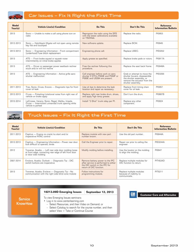
Car Issues – Fix It Right the First Time
Model Year(s) Vehicle Line(s)/Condition Do This Don’t Do This Reference
Information/Bulletin
2013 Sonic — Unable to make a call using phone icon on radio
Reprogram the radio using the SPS with the latest calibrations available on TIS2Web .
Replace the radio . PI0953
2012-2013 Sonic — Hatchback liftgate will not open using remote key fob and touchpad
New software update . Replace BCM . PI0945
2012-2013 Sonic — Engineering Information – Front compartment (underhood) fuse block replacement
Engineering phone call . Replace UBEC . PIE0252
2013 ATS — Front brake squeal or squeak noise intermittently on initial brake applies
Applygreaseasspecified. Replace brake pads or rotors . PI0917A
2013 ATS — Driver or passenger power seatback recliner stuckand/orwillnotrecline
Free the recliner following this procedure .
Replace the seat back frame . PI0948A
2013 ATS — Engineering Information – Active grille aero shutter malfunction
Call engineer before work on aero shutter if DTCs P069E and P059F or P069E and U0284 are present .
Grab or attempt to move the shutter louvers, disassemble the shutter assembly, or remove the actuator from the shutter assembly .
PIE0256
2011-2013 Trax,Sonic,Cruze,Encore—Diagnostictipsforfrontcover oil leak
Use oil dye to determine the leak location and repair as necessary .
Replace front timing chain cover for oil leak .
PI0957
2012-2013 Cruze—Pulsating/rotationalnoisefromrightrearofvehicle on brake apply
Replace right rear brake drum, shoes, and apply high temp grease .
Don't turn the drum . PI0887B
2010-2014 LaCrosse, Verano, Sonic, Regal, Malibu, Impala, Cruze—Intermittentunwantedtrunkopeningwhilevehicle is parked
Install “2-Shot” trunk relay per PI . Replace any other component .
PI0924
Truck Issues – Fix It Right the First Time
Model Year(s) Vehicle Line(s)/Condition Do This Don’t Do This Reference
Information/Bulletin
2011-2013 Captiva—Enginenocrank/nostartand/orinoperative HVAC control
Replace module with new part number known .
Use the old part number . PI0944A
2012-2013 Captiva — Engineering Information – Power rear door lockdifficulttooperate,binds
Call the Engineer prior to repair . Repair car prior to calling the engineer .
PIE0244A
2012 Traverse, Acadia — Left rear side door molding loose at front edge, contacting rear edge of left front door or door side molding
Modify molding before installing . Use the locator on the molding to align the molding .
PI0947
2007-2014 Enclave, Acadia, Outlook — Diagnostic Tip – DIC switch buttons are inoperative
Remove battery power to the IPC after service is performed to either the DIC switch or the IPC for return of DIC function .
Replace multiple modules for DIC function to return .
PIT4534D
2013 Traverse, Acadia, Enclave — Diagnostic Tip – No communicationwiththerightsideblindzonemodule
Follow instructions for programming module .
Replace multiple modules because of inability to communicate .
PIT5211
Customer Care and Aftersales Service
Know-How
10213.09D Emerging Issues
To view Emerging Issues seminars:• Logintowww.centerlearning.com
– SelectResources,andthenVideoonDemand;or– Select Catalog to search for the course number, and then
select View > Take or Continue Course
September 12, 2013


![Sony Fe2 Chassis Kd28dx40u [ET]](https://img.pdfslide.net/doc/110x75/5535bcd64a7959361a8b46c3/sony-fe2-chassis-kd28dx40u-et.jpg)